WO2014024666A1 - 静圧気体軸受ユニット - Google Patents
静圧気体軸受ユニット Download PDFInfo
- Publication number
- WO2014024666A1 WO2014024666A1 PCT/JP2013/069767 JP2013069767W WO2014024666A1 WO 2014024666 A1 WO2014024666 A1 WO 2014024666A1 JP 2013069767 W JP2013069767 W JP 2013069767W WO 2014024666 A1 WO2014024666 A1 WO 2014024666A1
- Authority
- WO
- WIPO (PCT)
- Prior art keywords
- shaft
- radial bearing
- thrust bearing
- air
- thrust
- Prior art date
- Legal status (The legal status is an assumption and is not a legal conclusion. Google has not performed a legal analysis and makes no representation as to the accuracy of the status listed.)
- Ceased
Links
Images


Classifications
-
- F—MECHANICAL ENGINEERING; LIGHTING; HEATING; WEAPONS; BLASTING
- F16—ENGINEERING ELEMENTS AND UNITS; GENERAL MEASURES FOR PRODUCING AND MAINTAINING EFFECTIVE FUNCTIONING OF MACHINES OR INSTALLATIONS; THERMAL INSULATION IN GENERAL
- F16C—SHAFTS; FLEXIBLE SHAFTS; ELEMENTS OR CRANKSHAFT MECHANISMS; ROTARY BODIES OTHER THAN GEARING ELEMENTS; BEARINGS
- F16C32/00—Bearings not otherwise provided for
- F16C32/06—Bearings not otherwise provided for with moving member supported by a fluid cushion formed, at least to a large extent, otherwise than by movement of the shaft, e.g. hydrostatic air-cushion bearings
- F16C32/0603—Bearings not otherwise provided for with moving member supported by a fluid cushion formed, at least to a large extent, otherwise than by movement of the shaft, e.g. hydrostatic air-cushion bearings supported by a gas cushion, e.g. an air cushion
- F16C32/0614—Bearings not otherwise provided for with moving member supported by a fluid cushion formed, at least to a large extent, otherwise than by movement of the shaft, e.g. hydrostatic air-cushion bearings supported by a gas cushion, e.g. an air cushion the gas being supplied under pressure, e.g. aerostatic bearings
- F16C32/0618—Bearings not otherwise provided for with moving member supported by a fluid cushion formed, at least to a large extent, otherwise than by movement of the shaft, e.g. hydrostatic air-cushion bearings supported by a gas cushion, e.g. an air cushion the gas being supplied under pressure, e.g. aerostatic bearings via porous material
-
- F—MECHANICAL ENGINEERING; LIGHTING; HEATING; WEAPONS; BLASTING
- F16—ENGINEERING ELEMENTS AND UNITS; GENERAL MEASURES FOR PRODUCING AND MAINTAINING EFFECTIVE FUNCTIONING OF MACHINES OR INSTALLATIONS; THERMAL INSULATION IN GENERAL
- F16C—SHAFTS; FLEXIBLE SHAFTS; ELEMENTS OR CRANKSHAFT MECHANISMS; ROTARY BODIES OTHER THAN GEARING ELEMENTS; BEARINGS
- F16C32/00—Bearings not otherwise provided for
- F16C32/06—Bearings not otherwise provided for with moving member supported by a fluid cushion formed, at least to a large extent, otherwise than by movement of the shaft, e.g. hydrostatic air-cushion bearings
- F16C32/0603—Bearings not otherwise provided for with moving member supported by a fluid cushion formed, at least to a large extent, otherwise than by movement of the shaft, e.g. hydrostatic air-cushion bearings supported by a gas cushion, e.g. an air cushion
- F16C32/0614—Bearings not otherwise provided for with moving member supported by a fluid cushion formed, at least to a large extent, otherwise than by movement of the shaft, e.g. hydrostatic air-cushion bearings supported by a gas cushion, e.g. an air cushion the gas being supplied under pressure, e.g. aerostatic bearings
- F16C32/0622—Bearings not otherwise provided for with moving member supported by a fluid cushion formed, at least to a large extent, otherwise than by movement of the shaft, e.g. hydrostatic air-cushion bearings supported by a gas cushion, e.g. an air cushion the gas being supplied under pressure, e.g. aerostatic bearings via nozzles, restrictors
-
- F—MECHANICAL ENGINEERING; LIGHTING; HEATING; WEAPONS; BLASTING
- F16—ENGINEERING ELEMENTS AND UNITS; GENERAL MEASURES FOR PRODUCING AND MAINTAINING EFFECTIVE FUNCTIONING OF MACHINES OR INSTALLATIONS; THERMAL INSULATION IN GENERAL
- F16C—SHAFTS; FLEXIBLE SHAFTS; ELEMENTS OR CRANKSHAFT MECHANISMS; ROTARY BODIES OTHER THAN GEARING ELEMENTS; BEARINGS
- F16C32/00—Bearings not otherwise provided for
- F16C32/06—Bearings not otherwise provided for with moving member supported by a fluid cushion formed, at least to a large extent, otherwise than by movement of the shaft, e.g. hydrostatic air-cushion bearings
- F16C32/0681—Construction or mounting aspects of hydrostatic bearings, for exclusively rotary movement, related to the direction of load
- F16C32/0685—Construction or mounting aspects of hydrostatic bearings, for exclusively rotary movement, related to the direction of load for radial load only
-
- F—MECHANICAL ENGINEERING; LIGHTING; HEATING; WEAPONS; BLASTING
- F16—ENGINEERING ELEMENTS AND UNITS; GENERAL MEASURES FOR PRODUCING AND MAINTAINING EFFECTIVE FUNCTIONING OF MACHINES OR INSTALLATIONS; THERMAL INSULATION IN GENERAL
- F16C—SHAFTS; FLEXIBLE SHAFTS; ELEMENTS OR CRANKSHAFT MECHANISMS; ROTARY BODIES OTHER THAN GEARING ELEMENTS; BEARINGS
- F16C32/00—Bearings not otherwise provided for
- F16C32/06—Bearings not otherwise provided for with moving member supported by a fluid cushion formed, at least to a large extent, otherwise than by movement of the shaft, e.g. hydrostatic air-cushion bearings
- F16C32/0681—Construction or mounting aspects of hydrostatic bearings, for exclusively rotary movement, related to the direction of load
- F16C32/0696—Construction or mounting aspects of hydrostatic bearings, for exclusively rotary movement, related to the direction of load for both radial and axial load
-
- F—MECHANICAL ENGINEERING; LIGHTING; HEATING; WEAPONS; BLASTING
- F16—ENGINEERING ELEMENTS AND UNITS; GENERAL MEASURES FOR PRODUCING AND MAINTAINING EFFECTIVE FUNCTIONING OF MACHINES OR INSTALLATIONS; THERMAL INSULATION IN GENERAL
- F16C—SHAFTS; FLEXIBLE SHAFTS; ELEMENTS OR CRANKSHAFT MECHANISMS; ROTARY BODIES OTHER THAN GEARING ELEMENTS; BEARINGS
- F16C2300/00—Application independent of particular apparatuses
- F16C2300/20—Application independent of particular apparatuses related to type of movement
- F16C2300/22—High-speed rotation
Definitions
- the present invention relates to a structure of a double-sided hydrostatic gas bearing unit that can support a component such as a pulley that rotates at a high speed with a simple structure and more stably without contact.
- Patent Document 1 describes an air bearing unit (static pressure air bearing device) that supports a rotating shaft in a non-contact manner.
- the shaft thrust load and radial load are respectively provided on both ends of the inner periphery of the cylindrical housing into which the shaft (rotating shaft) is inserted, and the individual bearing surfaces (thrust bearing surface, radial bearing surface)
- One air bearing (static air bearing) of a porous drawing type (a porous body such as porous graphite) received by each is provided.
- the radial bearing surface is opposed to the outer peripheral surface of the shaft and a radial bearing gap is formed between the radial bearing surface and the thrust bearing surface is opposed to the flange formed on the outer periphery of the shaft.
- a thrust bearing gap is formed between the flange and the flange.
- an exhaust groove is formed in the circumferential direction on the opposite side of the thrust bearing surface (center side of the inner peripheral surface of the housing) across the radial bearing surface of the air bearing
- An exhaust hole penetrating the outer peripheral surface of the housing is formed at the bottom of the exhaust groove.
- an exhaust groove is formed in the circumferential direction at a position near the thrust bearing surface of the air bearing on the outer peripheral surface of the shaft, and the exhaust groove and the inner peripheral surface of the housing are exhausted inside the shaft. Exhaust holes that connect the grooves are formed.
- the air supplied to the air bearing is ejected from the thrust bearing surface and the radial bearing surface of the air bearing.
- the air ejected from the thrust bearing surface flows in the thrust bearing gap toward the outer periphery of the flange, and is discharged to the outside through the thrust bearing gap.
- the air ejected from the radial bearing surface flows in the radial bearing gap toward the exhaust groove near the thrust bearing surface and the exhaust groove on the opposite side of the thrust bearing surface, and flows into these exhaust grooves. Then, the air is exhausted to the outside of the housing through the exhaust hole.
- the radial bearing gap is supplied to a position near the thrust bearing surface and a position on the opposite side of the thrust bearing surface across the radial bearing surface. It is necessary to form an exhaust groove for discharging the generated air. Further, it is necessary to form exhaust holes for discharging the air flowing into these exhaust grooves to the outside of the housing on both the housing and the shaft. Further, it is necessary to separately provide a thrust bearing surface and a radial bearing surface for ejecting compressed air on the inner periphery of the housing. This complicates the structure.
- the exhaust hole on the shaft side is formed along the axial direction of the shaft so as to connect the exhaust groove on the outer peripheral surface of the shaft and the exhaust groove on the inner peripheral surface of the housing. Thickness is required. For this reason, when the shaft becomes heavy, the shaft may be bent by its own weight, for example. Since the radial bearing gap formed between the radial bearing surface of the air bearing (hydrostatic air bearing) on the inner periphery of the housing and the outer peripheral surface of the shaft is very narrow, if the shaft is bent, the shaft and the air ring There is a possibility that the shaft cannot be held stably.
- the present invention has been made in view of the above circumstances, and an object of the present invention is to provide a structure of a double-sided hydrostatic gas bearing unit that supports a rotating body that rotates at a high speed with a simple structure and more stably in a non-contact manner. It is to provide.
- a shaft unit that is inserted into a shaft insertion hole formed in the rotating body in the axial direction of the rotating body and supports the rotating body in a non-contact manner is provided as a shaft of the rotating body. Fix the insertion hole at the position where it is sandwiched from both sides in the axial direction.
- the gas ejected from the radial bearing surface formed on the outer peripheral surface of the shaft unit opposite to the inner peripheral surface of the shaft insertion hole of the rotating body causes the radial bearing surface and the inner peripheral surface of the shaft insertion hole of the rotating body to A gas film is formed in the radial bearing gap, and the gas is exhausted from the radial bearing gap into the thrust bearing gap between the thrust bearing surface of the shaft unit and each end face of the rotating body.
- a gas film is also formed in the thrust bearing gap using the exhausted gas.
- the present invention is a hydrostatic gas bearing unit that supports a rotating body that rotates in a direction around an axis center in a non-contact manner by a gas film interposed between a radial bearing gap and first and second thrust bearing gaps.
- a shaft unit that is inserted into a shaft insertion hole that penetrates both end faces of the rotating body; Shaft holding means for holding the shaft unit at positions on both sides of the shaft insertion hole of the rotating body,
- the shaft unit is A radial bearing surface that opposes the inner peripheral surface of the shaft insertion hole, forms the radial bearing gap between the inner peripheral surface, and ejects gas for forming the gas film in the radial bearing gap;
- a first thrust bearing gap is formed adjacent to the radial bearing surface, opposed to one end face of the rotating body, and connected to one end side of the radial bearing gap between the end face and the first thrust bearing gap.
- a thrust bearing surface of A second thrust bearing gap is formed adjacent to the radial bearing surface, opposite the other end face of the rotating body, and between the end face and the second thrust bearing gap connected to the other end side of the radial bearing gap.
- a thrust bearing surface of The gas is It flows in the radial bearing gap toward the first thrust bearing gap and the second thrust bearing gap, and exhausts from the radial bearing gap to the first thrust bearing gap and the second thrust bearing gap, respectively. Then, the gas film is formed in the first thrust bearing gap and in the second thrust bearing gap, respectively.
- the present invention formed between the inner peripheral surface of the shaft insertion hole of the rotating body and the radial bearing surface formed on the outer peripheral surface of the shaft unit facing the inner peripheral surface of the shaft insertion hole of the rotating body.
- the compressed gas exhausted from the radial bearing gap is supplied to the thrust bearing gap formed between each end face of the rotating body and the thrust bearing surface of the shaft unit, and then exhausted to form a gas film in the thrust bearing gap. Therefore, there is no need to separately provide a groove and a hole for exhausting compressed gas from the radial bearing gap and a thrust bearing surface for ejecting compressed gas into the thrust bearing gap.
- the shaft unit that supports the rotating body in a non-contact manner is fixed at both ends, even when the shaft unit is elongated according to the size of the rotating body, the bending can be suppressed. And the shaft unit can be prevented from contacting each other. For this reason, it is possible to realize a double-sided static pressure gas bearing unit capable of supporting a rotating body rotating at high speed with a simple structure and more stably in a non-contact manner.
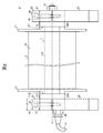
- FIG. 1 is an external view (without pulley 2) of a double-supported air bearing unit 4 according to an embodiment of the present invention.
- FIG. 2 is a side view of a double-ended air bearing unit 4 with the pulley 2 assembled according to an embodiment of the present invention.
- 3A is a front view of the pulley 2
- FIG. 3B is a cross-sectional view taken along the line AA in FIG. 4A.
- FIG. 4 is a part development view of the air shaft unit 1 according to the embodiment of the present invention.
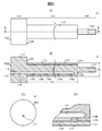
- 5A is a front view of the air shaft 11
- FIG. 5B is a cross-sectional view taken along the line BB of FIG. 5A
- FIG. 5C is a bottom view of the air shaft 11.
- FIG. 5A is a front view of the air shaft 11
- FIG. 5B is a cross-sectional view taken along the line BB of FIG. 5A
- FIG. 5C is a bottom view of the air shaft 11.
- FIG. 5D is an enlarged partial cross-sectional view of the radial bearing portion 114.
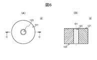
- 6A is a front view of the thrust plate 12, and
- FIG. 6B is a cross-sectional view taken along the line CC in FIG. 6A.
- FIG. 7 is a diagram schematically showing a support state of the pulley 2 during supply of air to the air shaft 11.
- a double-ended air bearing unit 4 suitable for non-contact support of a rotating body that is long in the direction of the axis O, such as a pulley 2 that feeds a wire such as an optical fiber or carbon fiber, is taken as an example.
- FIG. 1 is an external view of a double-sided air bearing unit 4 according to the present embodiment
- FIG. 2 is a side view of the double-sided air bearing unit 4 in a state where a pulley 2 to be supported is assembled. is there.
- a double-supported air bearing unit 4 includes an air shaft unit 1 that supports a pulley 2 that is long in the direction of the axis O in a non-contact manner, and an air shaft unit 1. And two shaft holders 3A and 3B that support both ends.
- the air shaft unit 1 is an assembly of an air shaft 11, a thrust plate 12 and a nut 13 (see FIG. 4), and the pulley 2 is for inserting an air shaft formed in the axial direction of the pulley 2.
- the air shaft 11 radial bearing portion 114 with the porous sintered layer 112 formed
- the air shaft 11 the screw portion 1151 of the rod portion 115
- the nut 13 through the thrust plate 12 are inserted.
- the air shaft unit 1 is assembled so as to be rotatable in a non-contact state.
- each shaft holder 3 ⁇ / b> A, 3 ⁇ / b> B has the end of the air shaft unit 1 (thrust plate 12, base portion 113 of the air shaft 11) with the axis O oriented substantially parallel to the base as the maximum diameter of the pulley 2. Hold at the appropriate height.
- Each of the shaft holders 3A and 3B includes, for example, a lower block member 33 with a flange 35 fixed to a pedestal with bolts, an upper block member 32 placed on the upper surface of the lower block member 33, and a lower block member. And two bolts 34 for adjusting the distance t1 between the upper surface of 33 and the bottom surface of the upper block member 33. Grooves having a semicircular cross section are formed in the thickness t2 direction on the upper surface of the lower block member 33 and the bottom surface of the upper block member 32, respectively, and these shafts face each other so that the shaft is positioned at a predetermined height. A fixing hole 31 is formed. The two bolts 34 are fastened to the screw holes of the lower block member 33 through the bolt holes of the upper block member 33 at positions on both sides of the shaft fixing hole 31.
- the end portions of the air shaft unit 1 (the thrust plate 12 and the base portion 113 of the air shaft 11) are respectively inserted into the shaft fixing holes 31 of the two shaft holders 3A and 3B arranged to face each other, and the respective shaft holders 3A and 3B are inserted.
- the two bolts 34 are tightened, the interval t1 between the lower block member 33 and the upper block member 32 is narrowed, and both end portions of the air shaft unit 1 (the thrust plate 12 and the base portion 113 of the air shaft 11) are fixed. Is done.
- attached to the air shaft unit 1 is hold
- the two shaft holders 3A and 3B are used to adjust the interval t1 between the lower block member 33 with the flange 35 and the upper block member 32 with the two bolts 34, but the air shaft Any type of shaft holder may be used as long as the unit 1 can be held at both ends thereof (thrust plate 12, base portion 113 of the air shaft 11).
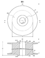
- FIG. 3 (A) is a front view of the pulley 2
- FIG. 3 (B) is a cross-sectional view taken along the line AA in FIG. 3 (A).
- the pulley 2 to be supported has, for example, a substantially cylindrical shape that is longer in the direction of the axis O than the diameter r2, and a wire rod is applied to the outer circumferential surface 23 in the circumferential direction.
- the pulley 2 is formed with an air shaft insertion hole 22 penetrating from one end face 25A to the other end face 25B at a position through which the axis O passes, and in the air shaft insertion hole 22, A radial bearing 114 with a porous sintered layer 112 of the air shaft 11 is slidably inserted.
- Bosses 24A and 24B surrounding the air shaft insertion hole 22 are formed on both end faces 25A and 25B of the pulley 2, respectively. End surfaces 241A and 241B of the bosses 24A and 24B are finished flat.
- the end surface 241A of one boss 24A has a slight gap (thrust bearing gap) and a step surface (thrust) (to be described later) of the air shaft 11 described later.
- Bearing surface) 1132 and the end surface 241B of the other boss 24B faces one end surface (thrust bearing surface) 121 of the thrust plate 12 with a slight gap (thrust bearing gap) (FIGS. 5 and 6). reference).
- annular flange portions 21 projecting radially from the outer peripheral surface 23 may be formed at both ends of the pulley 2.
- FIG. 4 is a component development view of the air shaft unit 1.
- the air shaft unit 1 is inserted into the air shaft insertion hole 22 of the pulley 2 and supports the pulley 2 in a non-contact manner so as to be rotatable around the axis O, and from the air shaft 11
- a thrust plate 12 that prevents the pulley 2 from falling off and a nut 13 that fixes the thrust plate 12 to the air shaft 11 are provided.
- FIG. 5A is a front view of the air shaft 11
- FIG. 5B is a cross-sectional view taken along the line BB of FIG. 5A
- FIG. 5C is a bottom view of the air shaft 11.
- FIG. 5D is an enlarged partial cross-sectional view of the radial bearing portion 114.
- the air shaft 11 includes a stepped columnar back metal 111 and a porous sintered layer 112 formed on the outer peripheral surface 1142 of the middle step portion (radial bearing portion) 114 of the back metal 111. I have.
- the back metal 111 includes a base portion 113 having substantially the same diameter as the outer diameters of the bosses 24 ⁇ / b> A and 24 ⁇ / b> B of the pulley 2, a radial bearing portion 114 having a smaller diameter than the base portion 113, and a rod portion 115 having a smaller diameter than the radial bearing portion 114. And are integrally provided.
- an air passage 116 is formed from the end surface 1131 through the inside of the base portion 113 to reach the inside of the radial bearing portion 114.
- a threaded portion 118 into which a coupler 40 (see FIG. 2) for connecting the air supply pipe 41 of the pump is screwed is formed at an opening (air supply port) 117 of the air passage 116 on one end surface 1131.
- the base portion 113 is inserted into the shaft fixing hole 31 of the one shaft holder 3A from the shaft fixing hole 31 of the one shaft holder 3A to the position where the other end surface 1132 protrudes toward the other shaft holder 3B (FIG. 2). reference). In this state, the two bolts 34 of the one shaft holder 3A are tightened, whereby the base portion 113 is fixed in the shaft fixing hole 31 of the one shaft holder 3A.
- the radial bearing 114 is formed integrally with the other end surface (step surface that functions as a thrust bearing surface) 1132 of the base 113, and a porous material having air permeability over the entire outer peripheral surface 1142 of the radial bearing 114.
- a sintered layer 112 is formed.
- a hole 1144 connected to the air passage 116 is formed.
- the number and layout of the annular grooves 1143 positioned on the outer peripheral surface 1142 of the radial bearing portion 114 may be determined as appropriate so that the compressed air is uniformly ejected from the entire outer peripheral surface 1121 of the porous sintered layer 112.
- a number of annular grooves 1143 corresponding to the length of the radial bearing portion 114 (width of the porous sintered layer 112) t4 and the like are arranged at substantially equal intervals in the axial center O direction of the porous sintered layer 112. Also good.
- the pressure of the entire radial bearing gap 60 such as a position away from the center position of the radial bearing portion 114 (a position inside t4 / 2 from one end of the radial bearing portion 114) to the base portion 113 side and the rod portion 115 side.
- the annular groove 1143 may be formed at a position where the height can be maintained high.
- the radial bearing 114 on which the porous sintered layer 112 is formed is inserted into the air shaft insertion hole 22 of the pulley 2.
- the outer diameter R1 of the radial bearing 114 including the porous sintered layer 112 is designed to be smaller than the inner diameter r1 (see FIG. 3) of the air shaft insertion hole 22 of the pulley 2 by a predetermined dimension. For this reason, when the radial bearing portion 114 is inserted into the air shaft insertion hole 22 of the pulley 2, the porous holes formed on the inner peripheral surface 221 of the air shaft insertion hole 22 and the outer peripheral surface 1142 of the radial bearing portion 114.
- a radial bearing gap 60 is formed between the outer peripheral surface (radial bearing surface) 1121 of the quality sintered layer 112 (see FIG. 7).
- a high-pressure air film is formed in the radial bearing gap 60 by the compressed air ejected from the outer peripheral surface (radial bearing surface) 1121 of the porous sintered layer 112 after the supply of air from the pump to the air shaft 11 is started. .
- the radial load is supported by the pressure of the air film.
- the length (distance between the stepped surfaces 1132 and 1141) t4 of the radial bearing 114 is based on the distance between the end surfaces 241A and 241B of the bosses 24A and 24B of the both ends 25A and 25B of the pulley 2 (length of the pulley 2) t3. Is designed to be larger by a predetermined dimension. For this reason, after the supply of air from the pump to the air shaft 11 is started, the end surface 241A of one boss 24A of the pulley 2 inserted into the radial bearing portion 114 and the other end surface of the base portion 113 (the radial bearing portion 114 and the base portion).
- a thrust bearing gap 61 a that is connected to the radial bearing gap 60 is formed between the outer diameter difference 113 and the step surface 1132 that functions as a thrust bearing surface. Similarly, it contacts the end surface 241B of the other boss 24B of the pulley 2 and the end surface of the radial bearing portion 114 (stepped surface formed by the difference in the outer diameter of the radial bearing portion 114 and the rod portion 115) 1141 as a thrust bearing surface.
- a thrust bearing gap 61b connected to the radial bearing gap 60 is also formed between one end surface 121 of a functioning thrust plate 12 described later (see FIG. 7). In order to prevent the occurrence of self-excited vibration, it is preferable to improve the assembling accuracy of the thrust plate 12 by finishing so that the edge portion 11411 of the end surface 1141 of the radial bearing portion 114 does not fall.
- the rod portion 115 is formed continuously with the end surface 1141 of the radial bearing portion 114, and is inserted into a shaft insertion hole 123 of the thrust plate 12 described later. Further, a screw portion 1151 that is screwed into the nut 13 is formed at the tip of the rod portion 115.
- FIG. 6A is a front view of the thrust plate 12, and FIG. 6B is a cross-sectional view taken along the line CC of FIG. 6A.
- the thrust plate 12 has a cylindrical shape having an outer diameter substantially the same as the outer diameter of the base portion 113 of the air shaft 11, and extends from one end surface 121 to the other surface 122 at a position through which the axis O passes.
- a penetrating shaft insertion hole 123 is formed. The rod portion 115 of the air shaft 11 is inserted into the shaft insertion hole 123.
- the air shaft unit 1 having the above-described configuration is assembled as follows.
- the pulley 2 is assembled to the air shaft unit 1. Specifically, the air shaft 11 is moved to the air shaft insertion hole 22 of the pulley 2 so that the radial bearing portion 114 on which the porous sintered layer 112 is formed is positioned in the air shaft insertion hole 22 of the pulley 2. Then, the air shaft 11 into which the pulley 2 is inserted is further inserted into the shaft insertion hole 123 of the thrust plate 12 so that the rod portion 115 is positioned in the shaft insertion hole 123 of the thrust plate 12.
- both ends thereof are It is fixed to two shaft holders 3A and 3B that are opposed to each other at a predetermined interval (see FIG. 2).
- the other end surface (step surface that functions as a thrust bearing surface) 1132 of the base portion 113 of the air shaft 11 protrudes from the shaft fixing hole 31 of one shaft holder 3A to the other shaft holder 3B side.
- the base portion 113 of the air shaft 11 is inserted into the shaft fixing hole 31 of one shaft holder 3A, and one end surface (end surface functioning as a thrust bearing surface) 121 of the thrust plate 12 is the shaft of the other shaft holder 3B.
- the thrust plate 12 is inserted into the shaft fixing hole 31 of the other shaft holder 3B so as to protrude from the fixing hole 31 toward the one shaft holder 3A. In this state, by tightening the two bolts 34 of the shaft holders 3A and 3B, the base portion 113 of the air shaft 11 and the thrust plate 12 are fixed in the shaft fixing holes 31 of the shaft holders 3A and 3B.
- a thrust bearing gap 61 a is formed between the end face 241 B of the other boss 24 B of the pulley 2 and one end face (thrust bearing face) 121 of the thrust plate 12. Is done. Compressed air exhausted from the radial bearing gap 60 flows into the thrust bearing gaps 61a and 61b, and a high-pressure air film is formed. The thrust load is supported by the pressure of the air film.
- the length t4 of the radial bearing 114 is such that the thickness s1 (see FIG. 7) of the thrust bearing gaps 61a and 61b on both sides of the pulley 2 is larger than the thickness s2 of the radial bearing gap 60 to the extent that no self-excited vibration is generated. Is also set to be large.
- the thrust bearing gaps 61a and 61b having a thickness s1 that does not generate self-excited vibration are a slight movement that occurs in the pulley 2 in a no-load state in the thrust direction, so that the pulley 2 is one thrust bearing.
- the thrust bearing gaps 61a and 61b are wide enough that they do not suddenly push back toward the other thrust bearing surface 121 or 1322, even if they are slightly closer to the surfaces 1132 and 121.
- the thickness s1 of the thrust bearing gaps 61a and 61b is about 22.5 to 37 ⁇ m.
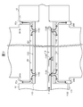
- FIG. 7 is a diagram schematically showing the support state of the pulley 2 during the supply of air to the air shaft 11.
- a pump air supply pipe (not shown) is connected to the air supply port 117 of the air shaft 11 and compressed air from the pump is connected.
- this compressed air f is supplied to each annular groove 1143 located on the outer peripheral surface 1142 of the radial bearing portion 114 via the air passage 116 and the hole 1144 of the air shaft 11, and porous sintering is performed. It is ejected from the outer peripheral surface (radial bearing surface) 1121 of the layer 112 into the radial bearing gap 60. For this reason, a high-pressure air film is formed in the radial bearing gap 60, and the radial load is supported by the pressure. Thereby, the movement to the radial direction of the pulley 2 is restrained.
- the compressed air f in the radial bearing gap 60 extends along the outer peripheral surface (radial bearing surface) 1121 of the porous sintered layer 112 on the one end surface (thrust bearing surface) 121 side of the thrust plate 12 and the base portion 113.
- the thrust bearing gap 61a between the end surface 241A of one boss 24A of the pulley 2 and the thrust bearing surface 1132 of the base portion 113 and the pulley 2 flows toward the other end surface (thrust bearing surface) 1132 side of the pulley 2.
- Compressed air f1 that has flowed into the thrust bearing gaps 61a and 61b flows radially toward the outer periphery of each boss 24A and 24B, and is finally released to the outside (atmospheric pressure).
- the pressure in each of the thrust bearing gaps 61a and 61b is high on the inner peripheral side of the pulley 2 into which the compressed gas f1 exhausted from the radial bearing gap 60 flows, and gradually increases toward the outer periphery of the bosses 24A and 24B. Decrease. For this reason, an air film having a high average pressure is formed in the thrust bearing gaps 61a and 61b, and the thrust load is supported by the pressure. Thereby, the movement of the pulley 2 in the thrust direction is restricted.
- the pressure distribution in the thrust bearing gaps 61a and 61b changes, and self-excited vibration may occur.
- the pressure increases due to the increase in resistance
- the pressure decreases due to the decrease in resistance. Moves along the axis O so as to be pushed back toward the other thrust bearing surface 121, 1322 only slightly closer to one thrust bearing surface 1132, 121. This is repeated.
- the thickness s1 has a margin enough to prevent the pulley 2 from being suddenly pushed back to the other thrust bearing surface 121, 1322 side. Since the thrust bearing gaps 61a and 61b are provided, the occurrence of self-excited vibration can be suppressed.
- compressed air is supplied from the porous sintered layer 112 facing the inner peripheral surface 221 of the pulley 2 to the radial bearing gap 60, and this radial bearing gap
- the compressed air exhausted from 60 is introduced into the thrust bearing gaps 61a and 61b on both sides of the pulley 2 while maintaining the pressure, so that the pressure of the air film in the radial bearing gap 60 and the thrust bearing gap 61a,
- the radial load and thrust load of the pulley 2 can be supported in a non-contact manner by the pressure of the air film in 61b. For this reason, since the power loss hardly occurs, the pulley 2 can be rotated at a high speed.
- the structure of the air bearing unit 4 can be further simplified, and the air bearing unit 4 can be reduced in manufacturing cost.
- the air shaft unit 1 is held at both ends thereof, even if the air shaft 11 is elongated to hold the long pulley 2, the air shaft 11 can be prevented from being bent by its own weight. Can do. Therefore, contact between the inner peripheral surface 221 of the air shaft insertion hole 22 of the pulley 2 and the outer peripheral surface (radial bearing surface) 1121 of the porous sintered layer 112 facing each other with a slight radial bearing gap 60 is prevented. can do. For this reason, even if the pulley 2 to be supported is elongated in the direction of the axis O, the pulley 2 can be stably supported in a non-contact manner.
- the thickness of the pulley 2 can be made thinner. For this reason, even if the pulley 2 is elongated in the direction of the axis O, the pulley 2 can be reduced in weight by making the pulley 2 thinner. Accordingly, the long pulley 2 can be rotated at a higher speed, and the load applied to the air shaft 11 is reduced, so that the bending of the air shaft 11 is further suppressed. For this reason, the pulley 2 that rotates at high speed can be supported in a non-contact manner more stably.
- the air bearing unit 4 it is only necessary that the compressed air is ejected from the radial bearing surface 1121 to the radial bearing gap 60, and the compressed gas is emitted from each of the thrust bearing surfaces 1132 and 121 and the radial bearing surface 1121. It is not necessary to attach a thick porous body that erupts. Therefore, the porous sintered layer 112 having a thickness of several millimeters (for example, about 2.5 mm) may be integrally formed with the back metal 111. For this reason, the air bearing unit 4 can be made compact.
- the air shaft 11 is inserted into the pulley 2 to be supported. It is sufficient if the air shaft insertion hole 22 is formed, and it is not necessary to form a special part. For this reason, the manufacturing cost of the pulley 2 which is a replacement part can be reduced, and the running cost can be reduced.
- the thickness s1 of the thrust bearing gaps 61a and 61b is increased to such an extent that no self-excited vibration is generated, the occurrence of self-excited vibration can be prevented. For this reason, the pulley 2 that rotates at high speed can be supported in a non-contact manner more stably.
- the stepped columnar back metal 111 is used, but the back metal 111 may have a hollow structure, for example.
- the air bearing unit 4 that supports the long pulley 2 is taken as an example, but a rotating body other than the long pulley 2 may be supported.
- a plurality of ordinary pulleys may be supported.
- the present invention can also be used as, for example, a dual-support type air bearing unit suitable for non-contact support of a rotating body such as a pulley for feeding a wire such as an optical fiber or carbon fiber.
- Air shaft unit 2: Pulley, 3A, 3B: Shaft holder, 4: Air bearing unit, 11: Air shaft, 12: Thrust plate, 13: Nut, 21: Flange, 22: Air shaft insertion hole, 23: Outer peripheral surface of boss, 24A, 24B: Boss, 25A, 25B: End surface of pulley, 111: Back metal, 112: Porous sintered layer, 113: Base portion, 114: Radial bearing portion, 115: Rod portion, 116: Air passage, 117: Air supply port, 118: Screw part, 121: End surface of thrust plate (thrust bearing surface), 122: End surface of thrust plate, 123: Hole for shaft insertion, 221: Inner peripheral surface of pulley, 241A, 241B: end face of the boss, 1121: outer peripheral surface of the porous sintered layer (radial bearing surface), 1131: base 1132: end surface of the base portion (step surface, thrust bearing surface), 1141: end surface of the radial bearing portion (step
Landscapes
- Engineering & Computer Science (AREA)
- General Engineering & Computer Science (AREA)
- Mechanical Engineering (AREA)
- Chemical & Material Sciences (AREA)
- Dispersion Chemistry (AREA)
- Magnetic Bearings And Hydrostatic Bearings (AREA)
Priority Applications (2)
| Application Number | Priority Date | Filing Date | Title |
|---|---|---|---|
| KR20157005284A KR20150038502A (ko) | 2012-08-10 | 2013-07-22 | 정압 기체 베어링 유닛 |
| CN201380041777.6A CN104541077B (zh) | 2012-08-10 | 2013-07-22 | 静压气体轴承单元 |
Applications Claiming Priority (2)
| Application Number | Priority Date | Filing Date | Title |
|---|---|---|---|
| JP2012-178123 | 2012-08-10 | ||
| JP2012178123A JP2014035054A (ja) | 2012-08-10 | 2012-08-10 | 静圧気体軸受ユニット |
Publications (1)
| Publication Number | Publication Date |
|---|---|
| WO2014024666A1 true WO2014024666A1 (ja) | 2014-02-13 |
Family
ID=50067900
Family Applications (1)
| Application Number | Title | Priority Date | Filing Date |
|---|---|---|---|
| PCT/JP2013/069767 Ceased WO2014024666A1 (ja) | 2012-08-10 | 2013-07-22 | 静圧気体軸受ユニット |
Country Status (5)
| Country | Link |
|---|---|
| JP (1) | JP2014035054A (enExample) |
| KR (1) | KR20150038502A (enExample) |
| CN (1) | CN104541077B (enExample) |
| TW (1) | TWI622715B (enExample) |
| WO (1) | WO2014024666A1 (enExample) |
Cited By (1)
| Publication number | Priority date | Publication date | Assignee | Title |
|---|---|---|---|---|
| US11067124B2 (en) * | 2018-07-23 | 2021-07-20 | Alio Industries, Inc. | Planar rotary air bearing stage |
Families Citing this family (8)
| Publication number | Priority date | Publication date | Assignee | Title |
|---|---|---|---|---|
| CN104614137B (zh) * | 2015-01-15 | 2016-08-31 | 浙江大学 | 基于静压气浮解耦装置的三分量标准振动台 |
| DE102015010875B9 (de) * | 2015-08-25 | 2016-12-29 | Thermo Electron (Karlsruhe) Gmbh | Rheometer mit Gaslager |
| DE112016007136T8 (de) | 2016-08-10 | 2019-05-09 | Kokusai Keisokuki Kabushiki Kaisha | Dynamische Auswuchtprüfvorrichtung |
| CN109955097B (zh) * | 2017-12-22 | 2020-09-01 | 上海理工大学 | 一种静压半球体轴承轴系及精密机床 |
| CN111285031B (zh) * | 2020-03-11 | 2021-09-14 | 上海精测半导体技术有限公司 | 一种旋转台 |
| CN111637161B (zh) * | 2020-05-18 | 2021-11-09 | 哈尔滨工程大学 | 一种带有分布式孔隙的强制润滑轴承 |
| CN111637159A (zh) * | 2020-05-18 | 2020-09-08 | 哈尔滨工程大学 | 一种带有加压孔的自适应强制润滑轴承 |
| CN111637160B (zh) * | 2020-05-18 | 2021-11-05 | 哈尔滨工程大学 | 一种带有不均匀孔径的强制润滑轴承 |
Citations (3)
| Publication number | Priority date | Publication date | Assignee | Title |
|---|---|---|---|---|
| JPH03292413A (ja) * | 1990-04-06 | 1991-12-24 | Nippon Seiko Kk | 多孔質体軸受ユニット |
| JPH11257467A (ja) * | 1998-03-06 | 1999-09-21 | Fujiwara:Kk | プーリー |
| JP2013068307A (ja) * | 2011-09-26 | 2013-04-18 | Oiles Corp | エアベアリングユニット |
Family Cites Families (6)
| Publication number | Priority date | Publication date | Assignee | Title |
|---|---|---|---|---|
| JPS5026251U (enExample) * | 1973-07-02 | 1975-03-26 | ||
| JPH0547543U (ja) * | 1991-11-29 | 1993-06-25 | 豊田工機株式会社 | 回転装置 |
| JP3653832B2 (ja) * | 1995-12-06 | 2005-06-02 | 日本精工株式会社 | 静圧気体軸受式回転案内装置 |
| JP3667108B2 (ja) * | 1998-08-31 | 2005-07-06 | 京セラ株式会社 | 糸状体のガイドローラ |
| DE102005007297B4 (de) * | 2005-02-17 | 2007-05-31 | Minebea Co., Ltd. | Fluiddynamisches Luftlagersystem zur Drehlagerung eines Motors |
| JP5812316B2 (ja) * | 2010-10-29 | 2015-11-11 | オイレス工業株式会社 | ロール装置 |
-
2012
- 2012-08-10 JP JP2012178123A patent/JP2014035054A/ja active Pending
-
2013
- 2013-07-02 TW TW102123628A patent/TWI622715B/zh active
- 2013-07-22 CN CN201380041777.6A patent/CN104541077B/zh active Active
- 2013-07-22 KR KR20157005284A patent/KR20150038502A/ko not_active Ceased
- 2013-07-22 WO PCT/JP2013/069767 patent/WO2014024666A1/ja not_active Ceased
Patent Citations (3)
| Publication number | Priority date | Publication date | Assignee | Title |
|---|---|---|---|---|
| JPH03292413A (ja) * | 1990-04-06 | 1991-12-24 | Nippon Seiko Kk | 多孔質体軸受ユニット |
| JPH11257467A (ja) * | 1998-03-06 | 1999-09-21 | Fujiwara:Kk | プーリー |
| JP2013068307A (ja) * | 2011-09-26 | 2013-04-18 | Oiles Corp | エアベアリングユニット |
Cited By (1)
| Publication number | Priority date | Publication date | Assignee | Title |
|---|---|---|---|---|
| US11067124B2 (en) * | 2018-07-23 | 2021-07-20 | Alio Industries, Inc. | Planar rotary air bearing stage |
Also Published As
| Publication number | Publication date |
|---|---|
| CN104541077B (zh) | 2018-05-08 |
| JP2014035054A (ja) | 2014-02-24 |
| TWI622715B (zh) | 2018-05-01 |
| KR20150038502A (ko) | 2015-04-08 |
| CN104541077A (zh) | 2015-04-22 |
| TW201420907A (zh) | 2014-06-01 |
Similar Documents
| Publication | Publication Date | Title |
|---|---|---|
| WO2014024666A1 (ja) | 静圧気体軸受ユニット | |
| JP5851780B2 (ja) | エアベアリングユニット | |
| JP6288999B2 (ja) | 静圧気体軸受装置 | |
| US9903415B2 (en) | Motor | |
| JP4276667B2 (ja) | 搭載真空発生装置を有する真空予荷重空気軸受け | |
| JP6444511B2 (ja) | フォイル軸受、フォイル軸受のギャップジオメトリを調節する方法、ならびにフォイル軸受の対応する製造方法 | |
| US20160068360A1 (en) | Gas bearing, porous media vacuum roller and porous media air turn | |
| JPH09296825A (ja) | 静圧気体軸受 | |
| CN104024668B (zh) | 静压气体轴承装置 | |
| US20200398291A1 (en) | Air turbine drive spindle | |
| KR101183697B1 (ko) | 롤 장치 | |
| US3719405A (en) | Gas bearing | |
| US11655851B2 (en) | Bearing device and rotating device | |
| JP3158709U (ja) | 空気軸受及び空気軸受を備えるスピンドル装置 | |
| JP6402459B2 (ja) | 静圧気体軸受回転案内装置 | |
| JP2015098876A (ja) | 静圧気体軸受およびこれを用いた回転装置 | |
| JP6177619B2 (ja) | 静圧気体軸受装置 | |
| JP2017009112A (ja) | 静圧気体軸受装置およびこれを用いた糸状体のガイドローラ | |
| JP2015175510A (ja) | 静圧気体軸受回転案内装置 | |
| JP2015175484A (ja) | 静圧流体軸受 | |
| KR101840006B1 (ko) | 다공성 세라믹 에어베어링 | |
| JP6500335B2 (ja) | 静圧気体軸受回転案内装置 | |
| TW201917303A (zh) | 多孔質氣靜壓軸承 | |
| CN117889151A (zh) | 一种小型高速表面节流的流体静压主轴 | |
| JP2009270631A (ja) | 静圧気体軸受 |
Legal Events
| Date | Code | Title | Description |
|---|---|---|---|
| 121 | Ep: the epo has been informed by wipo that ep was designated in this application |
Ref document number: 13827497 Country of ref document: EP Kind code of ref document: A1 |
|
| NENP | Non-entry into the national phase |
Ref country code: DE |
|
| ENP | Entry into the national phase |
Ref document number: 20157005284 Country of ref document: KR Kind code of ref document: A |
|
| 122 | Ep: pct application non-entry in european phase |
Ref document number: 13827497 Country of ref document: EP Kind code of ref document: A1 |