WO2013168564A1 - 電動パワーステアリング装置 - Google Patents
電動パワーステアリング装置 Download PDFInfo
- Publication number
- WO2013168564A1 WO2013168564A1 PCT/JP2013/061989 JP2013061989W WO2013168564A1 WO 2013168564 A1 WO2013168564 A1 WO 2013168564A1 JP 2013061989 W JP2013061989 W JP 2013061989W WO 2013168564 A1 WO2013168564 A1 WO 2013168564A1
- Authority
- WO
- WIPO (PCT)
- Prior art keywords
- electric power
- power steering
- vibration
- value
- amplitude
- Prior art date
- Legal status (The legal status is an assumption and is not a legal conclusion. Google has not performed a legal analysis and makes no representation as to the accuracy of the status listed.)
- Ceased
Links
Images


Classifications
-
- B—PERFORMING OPERATIONS; TRANSPORTING
- B62—LAND VEHICLES FOR TRAVELLING OTHERWISE THAN ON RAILS
- B62D—MOTOR VEHICLES; TRAILERS
- B62D5/00—Power-assisted or power-driven steering
- B62D5/04—Power-assisted or power-driven steering electrical, e.g. using an electric servo-motor connected to, or forming part of, the steering gear
- B62D5/0457—Power-assisted or power-driven steering electrical, e.g. using an electric servo-motor connected to, or forming part of, the steering gear characterised by control features of the drive means as such
- B62D5/046—Controlling the motor
- B62D5/0472—Controlling the motor for damping vibrations
-
- B—PERFORMING OPERATIONS; TRANSPORTING
- B62—LAND VEHICLES FOR TRAVELLING OTHERWISE THAN ON RAILS
- B62D—MOTOR VEHICLES; TRAILERS
- B62D5/00—Power-assisted or power-driven steering
- B62D5/04—Power-assisted or power-driven steering electrical, e.g. using an electric servo-motor connected to, or forming part of, the steering gear
- B62D5/0457—Power-assisted or power-driven steering electrical, e.g. using an electric servo-motor connected to, or forming part of, the steering gear characterised by control features of the drive means as such
- B62D5/046—Controlling the motor
- B62D5/0463—Controlling the motor calculating assisting torque from the motor based on driver input
-
- B—PERFORMING OPERATIONS; TRANSPORTING
- B62—LAND VEHICLES FOR TRAVELLING OTHERWISE THAN ON RAILS
- B62D—MOTOR VEHICLES; TRAILERS
- B62D6/00—Arrangements for automatically controlling steering depending on driving conditions sensed and responded to, e.g. control circuits
- B62D6/008—Control of feed-back to the steering input member, e.g. simulating road feel in steer-by-wire applications
-
- B—PERFORMING OPERATIONS; TRANSPORTING
- B62—LAND VEHICLES FOR TRAVELLING OTHERWISE THAN ON RAILS
- B62D—MOTOR VEHICLES; TRAILERS
- B62D7/00—Steering linkage; Stub axles or their mountings
- B62D7/06—Steering linkage; Stub axles or their mountings for individually-pivoted wheels, e.g. on king-pins
- B62D7/14—Steering linkage; Stub axles or their mountings for individually-pivoted wheels, e.g. on king-pins the pivotal axes being situated in more than one plane transverse to the longitudinal centre line of the vehicle, e.g. all-wheel steering
- B62D7/15—Steering linkage; Stub axles or their mountings for individually-pivoted wheels, e.g. on king-pins the pivotal axes being situated in more than one plane transverse to the longitudinal centre line of the vehicle, e.g. all-wheel steering characterised by means varying the ratio between the steering angles of the steered wheels
- B62D7/159—Steering linkage; Stub axles or their mountings for individually-pivoted wheels, e.g. on king-pins the pivotal axes being situated in more than one plane transverse to the longitudinal centre line of the vehicle, e.g. all-wheel steering characterised by means varying the ratio between the steering angles of the steered wheels characterised by computing methods or stabilisation processes or systems, e.g. responding to yaw rate, lateral wind, load, road condition
Definitions
- the present invention relates to an electric power steering apparatus that applies assist force by a motor to a steering system of a vehicle, and in particular, a torque ripple vibration component having a predetermined amplitude range and a predetermined frequency band according to the electric power steering state quantity.
- Vibration suppression compensation value calculated based on the vibration suppression compensation value calculated based on the extracted vibration component, or the electric power steering state quantity sensitive gain that changes the ratio of the extracted vibration component and vibration suppression compensation The present invention relates to an electric power steering apparatus in which torque ripple can be efficiently suppressed by feeding back a value to a control system, and deterioration in steering performance such as an increase in steering wheel viscosity can be minimized.
- An electric power steering device that applies a steering assist force (assist) to a steering mechanism of a vehicle by a rotational force of a motor is applied to a steering shaft or a rack shaft by a transmission mechanism such as a gear or a belt via a reduction gear.
- a steering assist force is applied.
- Such a conventional electric power steering apparatus performs feedback control of the motor current in order to accurately generate the torque of the steering assist force.
- the motor applied voltage is adjusted so that the difference between the steering assist command value (current command value) and the motor current detection value is small.
- the adjustment of the motor applied voltage is generally performed by PWM (pulse width). This is done by adjusting the duty of modulation) control.
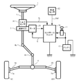
- a column shaft (steering shaft) 2 of the steering handle 1 is a reduction gear 3, universal joints 4a and 4b, a pinion rack mechanism 5, and tie rods 6a and 6b. Then, it is further connected to the steering wheels 8L, 8R via the hub units 7a, 7b. Further, the column shaft 2 is provided with a torque sensor 10 for detecting the steering torque of the steering handle 1, and a motor 20 for assisting the steering force of the steering handle 1 is applied to the column shaft 2 via the reduction gear 3. It is connected. Electric power is supplied from the battery 13 to the control unit 30 that controls the electric power steering device, and an ignition key signal is input through the ignition key 11.
- the control unit 30 calculates a steering assist command value of an assist (steering assist) command based on the steering torque Tr detected by the torque sensor 10 and the vehicle speed Vel detected by the vehicle speed sensor 12, and obtains the steering assist command value.
- the current supplied to the motor 20 is controlled by the current control value E subjected to compensation or the like.
- the vehicle speed Vel can also be received from CAN (Controller Area Network) or the like.
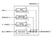
- the control unit 30 is mainly composed of a CPU (or MPU or MCU), and general functions executed by programs in the CPU are as shown in FIG.
- the function and operation of the control unit 30 will be described with reference to FIG. 2.
- the steering torque Tr detected by the torque sensor 10 and the vehicle speed Vel from the vehicle speed sensor 12 are input to the steering assist command value calculation unit 101, and an assist map is displayed. Using this, the steering assist command value Iref0 is calculated.
- the calculated steering assist command value Iref0 is limited in output by the maximum output limiting unit 102 based on overheat protection conditions and the like, and the current command value Iref whose maximum output is limited is input to the subtracting unit 103.
- the steering assist command value calculation unit 101 and the maximum output limit unit 102 are collectively referred to as a current command value determination unit 108.
- the calculation of the steering assist command value Iref0 in the steering assist command value calculation unit 101 can be further performed using the steering angle in addition to the steering torque Tr and the vehicle speed Vel.
- the controlled and controlled current control value E is input to the PWM (pulse width modulation) control unit 105 to calculate the duty, and the motor 20 is driven via the motor driving circuit 106 by the PWM signal PS having the duty calculated. .
- the motor current Im supplied to the motor 20 is detected by the motor current detection circuit 107, and the detected motor current Im is input to the subtraction unit 103 and fed back.
- the motor current is controlled by the current control value E, and the motor drive circuit 106 that drives the motor 20 uses a bridge circuit in which a semiconductor switching element (FET) and a motor are bridge-connected, and is determined based on the current control value E.
- FET semiconductor switching element
- a motor drive circuit configured to control the motor current by ON / OFF controlling the semiconductor switching element according to the duty of the PWM signal is used.
- the electric power steering device is a so-called man-machine interface mechanism that is easy to convey a feeling directly to the driver among automobile parts. It is taken up as a problem.
- the floor vibration caused by exciting the vehicle eigenvalue due to the torque ripple caused by the motor and mechanical mechanism is also a big problem because it also involves the operation sound problem of the vehicle system.
- Patent Document 1 JP-A-60-161257
- Patent Document 2 JP-A-2006-188183
- Patent Document 3 JP-A-2009-090953
- Patent Document 4 International Publication No. 2009/078074
- the vibration extraction method in the “vehicle motion control device” disclosed in Patent Document 1 extracts a vibration component in a specific (arbitrary) frequency band using Fourier transform from a sensor value (steering angle) for detecting a vehicle behavior. And it is the structure which suppresses a vibration by changing a control parameter according to the extracted vibration component of arbitrary frequency bands.
- the vibration extraction method in the “electric power steering device” disclosed in Patent Document 2 is a vibration center value calculated by moving average with respect to the steering torque, and a value obtained by extracting a specific vibration frequency by a bandpass filter. From the difference, a vibration component in an intended arbitrary frequency band is extracted, and the vibration is suppressed by changing a control parameter according to the extracted vibration component in an arbitrary frequency band.
- the vibration extraction method in the “electric power steering device” disclosed in Patent Document 3 applies reverse input stress by performing bandpass filter processing and RMS (mean square root) calculation on the steering angle (pinion angle).
- a specific frequency component 14 to 16 Hz
- RMS mean square root
- the steering pattern of the driver cannot be specified. Therefore, when the steering frequency inputted by the steering is synchronized with the specific frequency band (14 to 16 Hz), the specification is performed. There is a possibility that a steering component (steering frequency) intentionally input by the driver is mixed in the frequency band. Therefore, according to the vibration extraction method of Patent Document 3, there is a problem that in such a steering pattern, compensation works in the direction of inhibiting the steering pattern, which may cause a sense of incongruity.
- Patent Document 1 even in the vibration extraction method of Patent Document 3, when changing a control parameter, it is very important to confirm which control parameter should be changed and other contradictions to other performance. There is a problem that it tends to be complicated.
- the vibration extraction method in the “electric power steering control device” disclosed in Patent Document 4 is a technique that utilizes the fact that vibration components such as torque ripple and road surface disturbance have a smaller amplitude than the steering component of the steering wheel. Specifically, it is obtained by performing a hysteresis function process having a hysteresis width corresponding to a vibration component having an arbitrary amplitude on the dynamic state quantity (motor rotational speed or steering torque) of the electric power steering apparatus or the automobile. A vibration component (small vibration component) having an arbitrary amplitude is extracted based on the difference between the output and the dynamic state quantity, and a feedback control is performed by calculating a vibration compensation value (vibration suppression current) according to the extracted vibration component. A loop is formed.
- micro-line steering pattern the amplitude at the time of such a steering pattern (hereinafter referred to as “micro-line steering pattern”) is very small, according to the vibration extraction method of Patent Document 4, the amplitude at the time of the micro-line steering pattern is Since it falls within the range of the hysteresis width, vibration compensation that hinders the intention of the steering wheel is performed, and thus a problem that the steering wheel viscosity feeling increases occurs.
- the vehicle reaction force component from the tire includes road surface information (such as asphalt road surface and gravel road surface).
- road surface information such as asphalt road surface and gravel road surface.
- the amplitude of the road surface information is relatively small, it is necessary information for the driver. Such an information is very often desired to be transmitted to the steering person without being suppressed as an electric power steering device, but the road surface information has a small amplitude. The amplitude thereof falls within the range of the hysteresis width, and the road surface information may be compensated.
- the present invention has been made under the circumstances described above, and an object of the present invention is to extract and extract a torque ripple vibration component having an arbitrary amplitude and an arbitrary frequency band according to the electric power steering state quantity.
- an object of the present invention is to extract and extract a torque ripple vibration component having an arbitrary amplitude and an arbitrary frequency band according to the electric power steering state quantity.
- the present invention relates to an electric power steering apparatus that applies an assist force by a motor to a steering system of a vehicle, and the object of the present invention is to determine a current command value that determines a current command value based on a steering torque and a vehicle speed.
- a vibration extraction filter that extracts a vibration component having a predetermined amplitude and a predetermined frequency band according to the electric power steering state quantity, and a vibration suppression compensation value based on the vibration component extracted by the vibration extraction filter
- a compensation value calculation unit that calculates the vibration suppression compensation value calculated by the compensation value calculation unit to a current command value determined by the current command value determination unit, thereby reducing the vibration of the motor. This is achieved by suppressing.
- the vibration extraction filter includes a windowed reverse extraction characteristic filter that calculates a vibration center value according to the reverse characteristic of the predetermined frequency band based on the electric power steering state quantity. And extracting the vibration component having the predetermined amplitude and the predetermined frequency band based on the difference between the vibration center value and the electric power steering state quantity, or extracting inverse characteristic filter with window Includes an inverse characteristic filter having an inverse characteristic of the predetermined frequency band, and an amplitude window determination unit in which the predetermined amplitude is set in advance.
- the extraction inverse characteristic filter with window the electric power steering The state quantity is passed through the inverse characteristic filter, and then the output of the inverse characteristic filter is output to the amplitude window determination unit.
- the electric power steering state quantity is based on the past value of the vibration center value based on the electric power steering state quantity, the output of the inverse characteristic filter, and the past value of the vibration center value.
- an amplitude window determination process is performed to determine whether ⁇ the predetermined amplitude is within the range of the amplitude window.
- the output of the inverse characteristic filter is output as the vibration center value, and when it is determined that the electric power steering state quantity is outside the range of the amplitude window, the predetermined amplitude is added to or subtracted from the electric power steering state quantity. The value is achieved more effectively by being output as the vibration center value.
- the object of the present invention is to provide the extraction inverse characteristic filter with window having an inverse characteristic filter having an inverse characteristic of the predetermined frequency band, and an electric power related to a motor current amount with the predetermined amplitude set in advance.
- An amplitude window determination unit having a means for increasing / decreasing in accordance with the steering state quantity, and the windowed reverse extraction characteristic filter passes the electric power steering state quantity through the reverse characteristic filter and then the reverse characteristic.
- the output of the filter is output to the amplitude window determination unit, and the amplitude window determination unit increases or decreases the predetermined amplitude according to the electric power steering state quantity related to the motor current amount.
- an amplitude window determination process is performed to determine whether the electric power steering state quantity is within the range of the amplitude window of the past value of the vibration center value ⁇ the predetermined amplitude, When it is determined that the electric power steering state quantity is within the range of the amplitude window, the output of the inverse characteristic filter is output as the vibration center value, and the electric power steering state quantity is outside the range of the amplitude window.
- the value obtained by adding or subtracting the predetermined amplitude to or from the electric power steering state quantity is output as the vibration center value, or the electric power steering state quantity related to the motor current quantity Is the current command value or the steering torque, or the electric power related to the motor current amount.
- the dynamic power steering state quantity is the current command value
- the amplitude window determination unit sets the predetermined amplitude to increase in accordance with an increase in the current command value, or calculates the compensation value. Section calculates a sensitive gain for changing the vibration suppression compensation ratio according to the electric power steering state quantity related to the motor current amount and the electric power steering state quantity related to the speed, and calculates each of the calculated sensitive gains.
- the electric power steering state quantity related to the motor current amount is equal to or less than a predetermined threshold
- the electric power steering state related to the motor current amount is reduced when the ratio of the vibration suppression compensation value is reduced by reducing the sensitivity gain related to the amount, and the electric power steering state quantity related to the speed is equal to or greater than a predetermined threshold.
- the ratio of the vibration suppression compensation value is reduced, or the electric power steering state quantity related to the motor current quantity is the current command value or the steering torque.
- the electric power steering state quantity related to the speed is more effectively achieved by being a steering speed or a motor angular speed.
- the extraction inverse characteristic filter with window is an inverse characteristic filter having an inverse characteristic of the predetermined frequency band, and means for increasing or decreasing the predetermined amplitude set in advance according to the vehicle speed.
- An amplitude window determination unit comprising the window, and the extraction inverse characteristic filter with window passes the electric power steering state quantity through the inverse characteristic filter, and then outputs the output of the inverse characteristic filter to the amplitude window determination unit.
- the amplitude window determination unit increases or decreases the predetermined amplitude according to the vehicle speed to set the predetermined amplitude, and then outputs the electric power steering state quantity, the output of the inverse characteristic filter, And based on the past value of the vibration center value, the electric power steering state quantity is the past value of the vibration center value ⁇
- the amplitude window determination process is performed to determine whether or not the amplitude window is within a range of a constant amplitude, and the electric power steering state quantity is determined to be within the range of the amplitude window, the reverse characteristic
- a value obtained by multiplying the vibration suppression compensation value calculated based on the vibration component extracted by the extraction filter is the vibration suppression compensation value.
- the amplitude window determination unit sets the predetermined amplitude by decreasing the predetermined amplitude according to the vehicle speed, In the compensation value calculation unit, the vehicle speed sensitivity gain is reduced, thereby reducing the ratio of the vibration suppression compensation value more effectively.
- the predetermined frequency band is a frequency band other than a vibration component of a frequency band to be transmitted to a steering wheel as the electric power steering device, or the predetermined frequency band is The frequency band to be transmitted to the steering person as the electric power steering device and the frequency band other than the frequency band above the frequency at which the vibration extraction accuracy limited by sampling or the like deteriorates, or to the steering person
- the frequency band is a frequency band of about 10 [Hz] or less including road surface information, tire conditions, or the like
- the electric power steering state quantity is an electric power steering state quantity related to a motor current quantity, or The electric power steering state quantity related to speed, or
- the electric power steering state quantity related to the motor current amount is the steering torque, the current command value, or the detected motor current, or the electric power steering state quantity related to the speed is The electric power steering state quantity is obtained by multiplying the steering torque and the steering speed as steering energy, the current command value as the motor kinetic energy, the torque constant, and the motor angular speed. This is achieved more effectively
- a torque ripple vibration component having an arbitrary amplitude and an arbitrary frequency band can be extracted by the vibration extraction filter in accordance with the electric power steering state quantity.
- Vibration component with smaller amplitude than the steering component can be extracted efficiently, and the vibration component can be extracted while classifying the vibration component that should be returned to the driver such as road surface information and the vibration component that should be suppressed such as torque ripple and judder vibration. Therefore, torque ripple vibration can be efficiently suppressed while minimizing deterioration in steering performance.
- the electric power steering state quantity for example, current command value
- the electric power steering state quantity for example, the motor angular velocity
- the electric power steering state quantity sensitive gain for changing the vibration suppression compensation ratio is calculated. Therefore, the vibration waveform generated when the signal related to the motor current amount is small and the viscosity feeling when cutting out near the center can be suppressed and the signal related to the speed indicates high rotation. It is also possible to eliminate the influence of the deterioration of the extraction accuracy.
- the vibration suppression compensation value when calculating the vibration suppression compensation value based on the extracted vibration component, not only the electric power steering state quantity related to the motor current amount and the electric power steering state quantity related to the speed are used. Since the ratio of the vibration suppression compensation value is made variable according to the vehicle speed, the vibration suppression effect can be surely enhanced with respect to the amplitude change of the vibration component that changes according to the vehicle speed, and frequently Viscosity caused by fine steering near the on-center performed can also be eliminated.
- Example 1 of the electric power steering device it is a diagram showing a characteristic setting example of the extraction inverse characteristic filter with window (an example in which a predetermined frequency band to be extracted is a high-pass characteristic).
- Example 1 is a block diagram illustrating a configuration diagram of an extraction inverse characteristic filter with a window in Embodiment 1 of an electric power steering apparatus according to the present invention.
- Example 1 of the electric power steering device it is a diagram showing a characteristic setting example of the extraction inverse characteristic filter with window (an example in the case where a predetermined frequency band to be extracted is a band pass characteristic). It is a figure which shows the steering wheel vibration suppression effect by the presence or absence of the vibration compensation function by this invention. It is a figure which shows the Lissajous waveform of the steering torque with respect to a steering angle by the presence or absence of the vibration compensation function by this invention. It is a block diagram which shows the block diagram of Example 2 of the electric power steering apparatus which concerns on this invention.
- Example 2 of the electric power steering device which concerns on this invention It is a block diagram which shows the block diagram of the extraction inverse characteristic filter with a window. It is a figure which shows the variable amplitude setting example which makes predetermined amplitude variable according to an electric current command value in the vibration extraction filter in Example 2 of the electric power steering apparatus which concerns on this invention. It is a block diagram which shows the block diagram of Example 3 of the electric power steering apparatus which concerns on this invention. It is a block diagram which shows the block diagram of the compensation value calculation part in Example 3 of the electric power steering apparatus which concerns on this invention.
- Example 4 of the electric power steering apparatus which concerns on this invention.
- Example 4 of the electric power steering device which concerns on this invention it is a block diagram which shows the block diagram of an extraction inverse characteristic filter with a window.
- Example 4 of the compensation value calculation part in Example 4 of the electric power steering apparatus which concerns on this invention.
- the present invention utilizes the fact that torque ripple (torque vibration), which is a factor of floor vibration, appears prominently in the motor angular speed signal, which is an electric power steering state quantity, and the vibration component contained in the motor angular speed signal (motor angular speed) is reduced. Extracted by the vibration extraction filter (vibration extraction filter function), based on the extracted vibration component (vibration component signal), a vibration suppression compensation value for suppressing torque ripple is calculated, and the calculated vibration suppression compensation value is a current command.
- the present invention relates to an electric power steering apparatus capable of efficiently suppressing torque ripple caused by various factors by reducing the value to a value.
- the vibration suppression compensation value is calculated based not only on the extracted vibration component but also on the current command value and the motor angular velocity signal.
- the vibration suppression compensation value when calculating the vibration suppression compensation value, is calculated based not only on the extracted vibration component but also on the current command value, the motor angular velocity signal, and the vehicle speed. It may be calculated.
- the vibration extraction filter functions only within a predetermined amplitude range, and is arbitrary with respect to the electric power steering state quantity (motor angular velocity signal) input to the vibration extraction filter. It has an extraction inverse characteristic filter with a window having an inverse characteristic filter (for example, weighted average, low pass, high pass, band pass, etc.) that outputs a torque ripple vibration component having an inverse characteristic in the frequency band of Using the difference between the output of the filter (ie, the vibration center value) and the electric power steering state quantity (motor angular velocity signal) input to the vibration extraction filter, a torque ripple vibration component having an arbitrary amplitude and an arbitrary frequency band is obtained. Configured to extract.
- an extraction inverse characteristic filter with a window having an inverse characteristic filter (for example, weighted average, low pass, high pass, band pass, etc.) that outputs a torque ripple vibration component having an inverse characteristic in the frequency band of Using the difference between the output of the filter (ie, the vibration center value) and the electric power steering state quantity
- the vibration extraction filter according to the present invention has a predetermined frequency band inverse characteristic obtained by passing the electric power steering state quantity through the inverse characteristic filter if the electric power steering state quantity is within the predetermined amplitude range. And an extraction inverse characteristic filter with a window for calculating the vibration center value. The difference between the vibration center value calculated by the extraction inverse characteristic filter with window and the electric power steering state quantity is a predetermined amplitude and a predetermined value. A vibration component having a frequency band is extracted.
- the electric power steering apparatus according to the present invention having the vibration extraction filter can extract a torque ripple vibration component having an arbitrary amplitude and an arbitrary frequency band according to the electric power steering state quantity, Vibration components with smaller amplitude than steering components can be extracted efficiently, and vibration extraction is performed while classifying vibration components to be returned to the steering wheel such as road surface information and vibration components to be suppressed such as torque ripple and judder vibration. Therefore, when the electric power steering apparatus according to the present invention is applied, the torque ripple is efficiently performed while minimizing the deterioration of the steering performance (for example, the increase in the steering wheel sticking feeling generated in the case of the small line steering pattern). Vibration can be suppressed.
- the vibration center value is updated by a filter that performs extraction (that is, the extraction inverse characteristic filter with window), and if it is outside the predetermined amplitude range, the vibration center value is updated without passing through the extraction inverse characteristic filter with window.
- the electric power steering state quantity used in the present invention is a signal that can detect a vibration component in addition to the motor angular velocity signal described above, for example, the steering torque detected by the torque sensor, the steering speed, the power supply voltage, Of course, it is possible to use a signal such as a motor applied voltage.
- the steering person when a torque ripple vibration component having an arbitrary amplitude and an arbitrary frequency band is extracted by the vibration extraction filter in accordance with the electric power steering state quantity capable of detecting the vibration component, the steering person is used as the electric power steering device.
- the frequency band that does not want to be transmitted to the steering as an electric power steering device without extracting the vibration component of the frequency band that is desired to be transmitted to the vehicle that is, the vibration component of about 10 [Hz] or less including road surface information and tire condition
- Vibration components ie floor vibrations caused by system eigenvalue excitation, vibration components such as motor torque ripple
- the present invention can extract a torque ripple vibration component having an arbitrary amplitude and an arbitrary frequency band with a simple configuration, so that the steering power can be sensed as an electric power steering device while efficiently using microcomputer resources. Without causing it, it is possible to efficiently suppress vibration components caused by torque ripple, mechanical resonance, and the like.
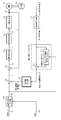
- FIG. 3 is a block diagram showing the configuration of the first embodiment of the electric power steering apparatus according to the present invention.
- the electric power steering apparatus is shown corresponding to FIGS. 1 and 2, and the same configuration is shown in FIG. The same reference numerals are used and description thereof is omitted.
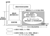
- FIG. 4 shows an example of frequency distribution of vibration components.
- FIG. 5 is a diagram illustrating a characteristic setting example of the extraction inverse characteristic filter with window (an example in which a predetermined frequency band to be extracted is a high-pass characteristic) in the first embodiment of the electric power steering apparatus according to the present invention. is there.
- the electric power steering state quantity is the motor angular velocity (motor angular velocity signal).
- the current command value determining unit 108 determines the current command value Iref based on the steering torque Tr detected by the torque sensor 10 and the vehicle speed Vel detected by the vehicle speed sensor 12. The determined current command value Iref is input to the subtraction unit 220.
- the motor current Im supplied to the motor 20 is detected by the motor current detection circuit 107, and the detected motor current Im is input to the subtraction unit 103.
- the rotor position detection sensor 200 (for example, a rotor position detector such as a resolver or a hall sensor) that detects the rotor position of the motor 20 detects the rotor rotation angle ⁇ as a rotor position signal.
- the angular velocity calculation unit 210 calculates the motor angular velocity ⁇ based on the rotor rotation angle ⁇ detected by the rotor position detection sensor 200. Then, the calculated motor angular velocity ⁇ is input to the vibration extraction filter 400 which is a main part of the present invention.
- the vibration extraction filter 400 extracts a vibration component having a predetermined amplitude and a predetermined frequency band based on the inputted motor angular velocity ⁇ , and the extracted vibration component VS is a compensation value which is another main part of the present invention. Input to the calculation unit 300.
- the compensation value calculation unit 300 calculates a vibration suppression compensation value CV based on the extracted vibration component VS, and the calculated vibration suppression compensation value CV is input to the subtraction unit 220.
- the vibration suppression compensation value CV is subtracted from the current command value Iref by the subtractor 220, that is, the vibration suppression compensation value CV is fed back to the current command value Iref, so that the vibration compensated current command is obtained.
- the value I is calculated.
- the calculated vibration-compensated current command value I is input to the subtraction unit 103.
- the controlled current control value E is input to the PWM control unit 105, the duty is calculated, and the motor 20 is driven via the motor drive circuit 106 by the PWM signal PS for which the duty is calculated.
- vibration component having “predetermined amplitude” and “predetermined frequency band” extracted by the vibration extraction filter 400 of the present invention that is, the vibration component to be compensated by the present invention
- the vibration components to be compensated by the present invention are mainly torque ripples generated by the motor, resonance vibrations generated by vibration inherent excitation of the vehicle frame and the like, vehicle reaction force components from tires, and the like. These vibration components have a smaller amplitude than the steering component of the steering person. That is, vibration components such as torque ripple and road surface disturbance have a smaller amplitude than the steering component of the steering wheel.
- the vibration extraction method of Patent Document 4 also uses this fact to extract a vibration waveform within a predetermined amplitude range, thereby extracting these vibration components.
- the steering wheel may steer the steering wheel in the vicinity of the on-center. Since the amplitude at the time of this micro line steering pattern is very small, according to the vibration extraction method of Patent Document 4, the vibration component is extracted only by the amplitude. As a result, it is recognized as a component and compensated. As a result, the steering viscosity increases and the steering fluffy feeling occurs.
- the vehicle reaction force component from the tire includes road surface information (such as asphalt road surface and gravel road surface).
- road surface information such as asphalt road surface and gravel road surface.
- the amplitude of the road surface information is relatively small, it is necessary information for the driver. Such an information is very often desired to be transmitted to the steering person without being suppressed as an electric power steering device, but the road surface information has a small amplitude. The amplitude becomes within the range of the hysteresis width, and there is a problem that road surface information is compensated.
- Fig. 4 shows an example of frequency and vibration component amplitude distribution.
- the vibration components to be compensated in the present invention are the mechanism, the natural vibration component of the vehicle, and the motor torque ripple that are felt as uncomfortable by the driver.
- the vibration component (that is, information to be fed back to the driver) is the driver's steering component, road surface information, and the like, and these vibration components that are not to be compensated are distributed in about 10 [Hz] or less.
- the electric power steering apparatus does not affect the steering feeling.
- the steering performance is improved by efficiently suppressing the vibration component that causes a sense of incongruity.
- the “predetermined frequency band” referred to in the present invention means a frequency band of a vibration component to be compensated in the present invention.
- the vibration extraction filter 400 includes a subtraction unit 410 and a windowed extraction inverse characteristic filter 420. Processing (operation) performed by the vibration extraction filter 400 is as follows.
- the vibration extraction filter 400 uses the extraction inverse characteristic filter with window 420 to extract vibration components having inverse characteristics of “predetermined amplitude” and “predetermined frequency band” with respect to the motor angular velocity ⁇ from the angular velocity calculation unit 210. Extract.
- a vibration component having inverse characteristics of “predetermined amplitude” and “predetermined frequency band” is output from the extraction inverse characteristic filter with window 420 as the vibration center value VCV.
- the vibration extraction filter 400 uses the subtraction unit 410 to extract the vibration component having the inverse characteristics of the “predetermined amplitude” and the “predetermined frequency band” (that is, the vibration center value VCV), the motor angular velocity ⁇ , and the like.
- the vibration component VS having “predetermined amplitude” and “predetermined frequency band” is extracted.
- the vibration component VS having “predetermined amplitude” and “predetermined frequency band” extracted by the vibration extraction filter 400 is input to the compensation value calculation unit 300.
- the “reverse characteristics” referred to in the present invention is a characteristic in which, for example, the frequency of information that is not desired to be compensated as shown in FIG. In the example of FIG. 4, since the vibration component of about 10 [Hz] or less is not extracted, the “reverse characteristic” of the present invention is a low-pass characteristic with a cutoff of about 10 [Hz].
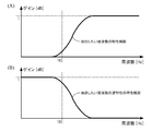
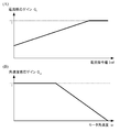
- FIG. 5 shows a characteristic setting example of the extraction inverse characteristic filter with window 420 when the “predetermined frequency band” extracted by the vibration extraction filter 400 is a high-pass characteristic.
- FIG. 5A shows a characteristic diagram of a frequency band having a high-pass characteristic extracted by the vibration extraction filter 400.
- FIG. 5B shows a characteristic diagram of the inverse characteristic of the frequency band having the high-pass characteristic as shown in FIG. 5A (that is, the characteristic line of the inverse characteristic of the extraction inverse characteristic filter with window 420). Figure).
- FIG. 6 is a block diagram showing a configuration diagram of the extraction inverse characteristic filter with window 420 in the first embodiment of the electric power steering apparatus according to the present invention. The function and operation of the extraction inverse characteristic filter with window 420 will be described with reference to FIG.
- the extraction inverse characteristic filter with window 420 includes an inverse characteristic filter 421 having an inverse characteristic of “predetermined frequency band” and an amplitude window determination unit in which “predetermined amplitude” is preset. 422 and a past value holding unit 423 that holds a vibration center past value.
- the processing (operation) performed by the extraction inverse characteristic filter with window 420 for the input motor angular velocity ⁇ is as follows.
- the extraction inverse characteristic filter with window 420 passes the motor angular velocity ⁇ through the inverse characteristic filter 421 and outputs the output through the inverse characteristic filter 421 (that is, the output of the inverse characteristic filter 421) ICO to the amplitude window determination unit 422.
- the inverse characteristic of “predetermined frequency” possessed by the inverse characteristic filter 421 is, for example, the inverse characteristic of the frequency characteristic to be extracted as shown in FIG.
- the extraction inverse characteristic filter with window 420 uses the amplitude window determination unit 422 to output the motor angular velocity ⁇ , the output ICO of the inverse characteristic filter 421, and the vibration center past value VCPV from the past value holding unit 423 (that is, vibration). Based on the past value of the center value VCV), an amplitude window determination process is performed to determine whether or not the motor angular velocity ⁇ is within the range of the amplitude window.
- the amplitude window determination unit 422 When it is determined by the amplitude window determination processing that the motor angular velocity ⁇ is within the range of the amplitude window, the amplitude window determination unit 422 outputs the output ICO of the inverse characteristic filter 421 as the vibration center value VCV.
- the amplitude window determination unit 422 adds the value obtained by adding or subtracting “predetermined amplitude” to the motor angular velocity ⁇ as the vibration center value. Output as VCV.
- the “amplitude window” referred to in the present invention means a range of vibration center past value VCPV ⁇ “predetermined amplitude”.
- the amplitude window determination unit 422 outputs the vibration center value VCV from the amplitude window determination unit 422 to the subtraction unit 410 and also outputs it to the past value holding unit 423.
- the past value holding unit 423 holds the input vibration center value VCV as the vibration center past value VCPV.
- the vibration extraction filter 400 can extract a vibration component in a predetermined amplitude and a predetermined frequency band, and can perform vibration compensation without deteriorating the steering component.
- FIG. 7 shows the vibration extraction result by the vibration extraction filter 400 of the present invention and the vibration extraction result by the conventional vibration extraction method in order to demonstrate the excellent vibration extraction effect of the vibration extraction filter 400 of the present invention.
- the vibration extraction method of Patent Document 4 was used as a conventional vibration extraction method.
- the “amplitude window” in FIG. 7B showing the vibration extraction result by the vibration extraction filter 400 of the present invention means the vibration center value ⁇ “predetermined amplitude”.
- the hysteresis width in the vibration extraction method of Patent Document 4 and the vibration extraction filter 400 of the present invention was set to be the same value.
- the same signal was used as a required motor angular velocity signal when extracting the vibration component.
- the vibration extraction filter 400 of the present invention the superimposition of the low-frequency steering component on the extracted vibration component is suppressed. Thereby, it is possible to suppress vibration while suppressing the influence on the steering feeling by the vibration suppressing function.
- the past value of the vibration center value is used in the processing performed by the extraction inverse characteristic filter with window.
- the output of the inverse characteristic filter 421 is smoothly connected to the output switching by the amplitude window determination unit 422, and there is an advantage that there is no sense of incongruity even if the inside and outside of the predetermined amplitude range are frequently switched.
- the “predetermined frequency band” extracted by the vibration extraction filter 400 is a high-pass characteristic having a cut-off of 10 [Hz].
- the present invention is not limited to this, and vibration extraction is performed.
- a “predetermined frequency band” extracted by a filter may be a bandpass characteristic.
- FIG. 8 shows a characteristic setting example of the extraction inverse characteristic filter with window when the “predetermined frequency band” extracted by the vibration extraction filter of the present invention is a bandpass characteristic.
- FIG. 8A shows a characteristic diagram of a frequency band having a bandpass characteristic extracted by a vibration extraction filter.
- FIG. 8B shows a characteristic diagram of the reverse characteristic of the frequency band having the bandpass characteristic as shown in FIG. 8A (that is, the characteristic line of the reverse characteristic of the extraction inverse characteristic filter with window). Figure).
- the compensation value calculation unit 300 is based on the vibration component VS having “predetermined amplitude” and “predetermined frequency band” extracted by the vibration extraction filter 400, and the vibration suppression compensation value CV. Is calculated.
- the vibration component VS having “predetermined amplitude” and “predetermined frequency band” extracted by the vibration extraction filter 400 is the electric power steering state when the electric power steering device according to the first embodiment is applied. Since the quantity is the motor angular velocity (motor angular velocity signal), it is the dimension of the motor angular velocity.
- the compensation value calculation unit 300 needs to convert the dimension of the motor angular velocity into the dimension of current. With regard to the conversion method, a sufficient effect can be obtained even if it is simply configured with a gain.
- the motor angular velocity dimension may be converted to the current dimension using the equation of motion expressed by the following equation (1).
- the denominator of the following equation of motion has approximate differential characteristics that take into account the effects of noise and the like.
- J is a motor (system) inertia term
- D is a motor (system) viscosity term
- Kt is a torque constant
- T 1 is an approximate differential time constant.
- a phase lead / lag characteristic filter and a PID controller may be configured.
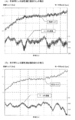
- FIG. 9A shows the handle vibration suppression effect without the vibration compensation function according to the present invention
- FIG. 9B shows the handle vibration suppression with the vibration compensation function according to the present invention. It shows the effect.
- the vibration compensation function according to the present invention is applied to the electric power steering device, so that the steering torque vibration is reduced, and the vibration component that appears in the motor angular velocity is also obtained. You can see that it is suppressed.
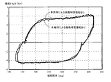
- FIG. 10 is a diagram showing a Lissajous waveform of the steering torque with respect to the steering angle with and without the vibration compensation function according to the present invention. From FIG. 10, there is almost no change in the Lissajous waveform when the vibration compensation function according to the invention is applied to the electric power steering apparatus and when the vibration compensation function according to the invention is not applied to the electric power steering apparatus. It can be confirmed that the function does not affect the steering.
- the vibration component to be compensated is mainly due to the torque ripple component of the motor, and the torque ripple of the motor generally tends to have a larger ripple width depending on the amount of current flowing to the motor. There is.
- the above-described extraction inverse characteristic filter with window 420 of the first embodiment can extract the vibration component only in an arbitrary frequency band (predetermined frequency band), but completely removes the steering component of the driver in the low frequency band. If the preset “predetermined amplitude” value is large and the steering speed is somewhat high during on-center steering, the vibration extraction result by the vibration extraction filter 400 according to the first embodiment is included in the steering component. May overlap slightly.
- the electric power steering state quantity related to the motor current quantity such as the steering torque or the current command value (hereinafter also referred to as “signal related to the motor current quantity”) is used. Accordingly, by changing the value of “predetermined amplitude” preset in the amplitude window determination unit, an optimal “predetermined value” according to the vibration component that changes according to the “signal related to the motor current amount”.
- the value of “Amplitude” can be set.
- the “predetermined amplitude” preset in the amplitude window determination unit is increased / decreased according to the electric power steering state quantity (steering torque or current command value) related to the motor current quantity (enlargement / Therefore, it is possible to improve the accuracy of extracting torque ripple components and perform highly accurate vibration compensation.
- the electric power steering apparatus according to the second embodiment of the present invention will be described when the electric power steering state quantity (signal related to the motor current quantity) related to the motor current quantity is used as the current command value.
- FIG. 11 is a block diagram showing a configuration diagram of Embodiment 2 of the electric power steering apparatus according to the present invention.
- the electric power steering apparatus is shown corresponding to FIGS. 1 and 2, and the same configuration is shown in FIG. The same reference numerals are used and description thereof is omitted.
- the electric power steering state quantity is the motor angular velocity (motor angular velocity signal).
- the configuration of the electric power steering apparatus according to the second embodiment of the present invention shown in FIG. 11 is the same as the configuration of the electric power steering apparatus according to the first embodiment of the present invention shown in FIG. Description of the same configuration is omitted.
- the electric power steering apparatus according to the first embodiment of the present invention shown in FIG. 3 includes the vibration extraction filter 400, whereas the electric power steering apparatus according to the second embodiment of the present invention shown in FIG. includes a vibration extraction filter 500.
- the vibration extraction filter 500 includes a subtraction unit 510 and a windowed extraction inverse characteristic filter 520. Processing (operation) performed by the vibration extraction filter 500 is as follows.
- the vibration extraction filter 500 detects vibration components having inverse characteristics of “predetermined amplitude” and “predetermined frequency band” in the extraction inverse characteristic filter with window 520 with respect to the motor angular velocity ⁇ from the angular velocity calculation unit 210. Extract.
- a vibration component having inverse characteristics of “predetermined amplitude” and “predetermined frequency band” is output from the extraction inverse characteristic filter with window 520 as the vibration center value VCV.
- the vibration extraction filter 500 uses the subtraction unit 510 to extract the vibration component having the reverse characteristics of the “predetermined amplitude” and the “predetermined frequency band” (that is, the vibration center value VCV), the motor angular velocity ⁇ , Thus, the vibration component VS having “predetermined amplitude” and “predetermined frequency band” is extracted.
- the vibration component VS having “predetermined amplitude” and “predetermined frequency band” extracted by the vibration extraction filter 500 is input to the compensation value calculation unit 300.
- FIG. 12 is a block diagram showing a configuration diagram of the extraction inverse characteristic filter with window 520 in the second embodiment of the electric power steering apparatus according to the present invention. The function and operation of the extraction inverse characteristic filter with window 520 will be described with reference to FIG.
- the extraction inverse characteristic filter with window 520 includes an inverse characteristic filter 421 having an inverse characteristic of “predetermined frequency” and a “predetermined amplitude” set in advance according to the current command value.
- An amplitude window determination unit 522 having means for increasing / decreasing and a past value holding unit 423 holding a vibration center past value are provided.
- the processing (operation) performed by the extraction inverse characteristic filter with window 520 for the input motor angular velocity ⁇ is as follows.
- the extraction inverse characteristic filter with window 520 passes the motor angular velocity ⁇ through the inverse characteristic filter 421, and outputs the output through the inverse characteristic filter 421 (that is, the output of the inverse characteristic filter 421) ICO to the amplitude window determination unit 522.
- the inverse characteristic of “predetermined frequency” possessed by the inverse characteristic filter 421 is, for example, the inverse characteristic of the frequency characteristic to be extracted as shown in FIG.
- the extraction inverse characteristic filter with window 520 increases or decreases the “predetermined amplitude” set in advance according to the current command value Iref from the current command value determination unit 108 in the amplitude window determination unit 522.
- the motor angular velocity ⁇ is within the range of the amplitude window.
- An amplitude window determination process is performed to determine whether or not.
- the amplitude window determination unit 522 When it is determined by the amplitude window determination process that the motor angular velocity ⁇ is within the range of the amplitude window, the amplitude window determination unit 522 outputs the output ICO of the inverse characteristic filter 421 as the vibration center value VCV.
- the amplitude window determination unit 522 adds the value obtained by adding or subtracting “predetermined amplitude” to the motor angular velocity ⁇ as the vibration center value. Output as VCV.
- the amplitude window determination unit 522 outputs the vibration center value VCV from the amplitude window determination unit 522 to the subtraction unit 410 and also outputs it to the past value holding unit 423.
- the past value holding unit 423 holds the input vibration center value VCV as the vibration center past value VCPV.
- the “amplitude window” referred to in the amplitude window determination unit 522 means a range of the vibration center past value VCPV ⁇ “predetermined amplitude”, and the “predetermined amplitude” corresponds to the current command value Iref.
- the “predetermined amplitude” obtained (set) by increasing or decreasing the “predetermined amplitude” set in advance.
- FIG. 13 shows a variable amplitude setting example in which the amplitude window determination unit 522 makes the predetermined amplitude variable according to the current command value Iref in the extraction inverse characteristic filter with window 520 of the second embodiment.
- the predetermined amplitude is set so as to increase the predetermined amplitude in accordance with the increase in the current command value Iref.
- the second embodiment adopts a configuration in which the predetermined amplitude is variable according to the current command value or the steering torque.
- this configuration shown in the second embodiment is adopted, in order to compensate for vibrations caused by no-load rotation of the motor, that is, motor cogging torque, loss torque fluctuation, mechanical mechanism vibration, etc.
- the “predetermined amplitude” set according to the current command value is set to a certain value.
- a sticky feeling may occur especially when the vehicle is cut from the center and steered.
- the waveform of the vibration component may not be accurately extracted due to the sampling relationship in practice.
- the vibration frequency such as torque ripple becomes very high, so that it is difficult for the driver to detect it as vibration, and it is considered that there is no need to perform compensation itself for such vibration.
- the compensation value calculation unit that calculates the vibration suppression compensation value CV
- the electric power steering state quantity related to the motor current amount and the electric power steering related to the speed are used.
- a sensitivity gain that changes the compensation ratio is calculated according to the state quantity, and each calculated sensitivity gain is converted into a vibration component VS having “predetermined amplitude” and “predetermined frequency band” extracted by the vibration extraction filter.
- the vibration suppression compensation value CV is calculated by multiplying the vibration suppression compensation value CV0 calculated on the basis thereof.
- the electric power steering state quantity related to the motor current quantity means a signal related to the motor current quantity, that is, means a steering torque or a current command value.
- the electric power steering state quantity related to the speed means a signal related to the speed, that is, a steering speed or a motor angular speed.
- the signal related to the motor current amount when the signal related to the motor current amount is small, that is, when the electric power steering state amount related to the motor current amount is equal to or less than a predetermined threshold, the signal related to the motor current amount By reducing the sensitivity gain and reducing the ratio of the vibration suppression compensation value, the viscous feeling at the time of cutting out near the on-center is suppressed.
- the sensitivity gain related to the speed-related signal is reduced to reduce vibration.
- the compensation ratio is increased / decreased according to the signal related to the speed (steering speed or motor angular speed). Therefore, by reducing the vibration suppression compensation value before the accuracy of vibration compensation is reduced. The above problem can be avoided.
- the electric power steering apparatus according to the third embodiment of the present invention is used. Will be described.
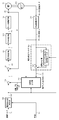
- FIG. 14 is a block diagram showing a configuration diagram of Embodiment 3 of the electric power steering apparatus according to the present invention.
- the electric power steering apparatus is shown corresponding to FIGS. 1 and 2, and the same configuration is shown in FIG. The same reference numerals are used and description thereof is omitted.
- the electric power steering state quantity is the motor angular velocity (motor angular velocity signal).
- the configuration of the electric power steering apparatus according to the third embodiment of the present invention shown in FIG. 14 is the same as the configuration of the electric power steering apparatus according to the second embodiment of the present invention shown in FIG. Therefore, the description about the same configuration is omitted.
- the electric power steering apparatus according to the second embodiment of the present invention shown in FIG. 11 includes the compensation value calculation unit 300, whereas the electric power steering according to the third embodiment of the present invention shown in FIG.
- the steering apparatus includes a compensation value calculation unit 310.
- FIG. 15 is a block diagram showing a configuration diagram of the compensation value calculation unit 310.
- FIG. 16 is a diagram showing a current sensitive gain setting example and an angular velocity sensitive gain setting example in the compensation value calculation unit 310 shown in FIG.
- the function and operation of the compensation value calculation unit 310 will be described with reference to FIGS. 15 and 16.
- the compensation value calculation unit 310 includes a current command value sensitive gain calculation unit 311, an angular velocity sensitive gain calculation unit 312, a compensation value calculation unit 313, a multiplication unit 314, and a multiplication unit 315. I have.
- the processing (operation) performed by the compensation value calculation unit 310 is as follows.
- the compensation value calculation section 310 with respect to the current command value Iref from the current command value determining section 108, and calculates a current command value sensitive gain G I at a current command value sensitive gain calculating unit 311, the angular velocity calculating unit 210
- the angular velocity sensitive gain G ⁇ is calculated by the angular velocity sensitive gain calculating unit 312 and the compensation value calculating unit 313 generates vibration based on the vibration component VS extracted by the vibration extracting filter 500.
- a suppression compensation value CV0 is calculated.
- the current command value sensitive gain calculating unit 31 for example, based on the current sensitive gain setting example of FIG. 16 (A), the also possible to calculate the current command value sensitive gain G I corresponding to the current command value Iref good.
- the angular velocity sensing gain calculating section 312 for example, based on the angular velocity sensitive gain setting example of FIG. 16 (B), the may be calculated angular velocity sensitive gain G omega corresponding to the motor angular velocity omega.
- the compensation value calculation unit 313 is the same as the configuration of the compensation value calculation unit 300 in the first embodiment, the description thereof is omitted.
- the compensation value calculated by the compensation value calculation unit 300 in the first embodiment is the vibration suppression compensation value CV
- the compensation value calculated by the compensation value calculation unit 313 in the third embodiment is the vibration suppression compensation value CV0.
- the compensation value calculation unit 310 at the multiplication unit 314 and the multiplying unit 315 is multiplied by a current instruction value sensitive gain G I and the angular velocity sensitive gain G omega to the vibration suppression compensation value CV0, the vibration suppression compensation value CV Ask for.
- the vibration suppression compensation value CV calculated by the compensation value calculation unit 310 is input to the subtraction unit 220.
- Example 3 when Example 3 is applied, it is possible to suppress the feeling of viscosity at the time of clipping near the on-center, which occurs when the number of signals related to the motor current is small, and the speed-related signal indicates high rotation It is also possible to eliminate the influence caused by the deterioration of the vibration waveform extraction accuracy.
- the vibration extraction filter of the present invention if the value of “predetermined amplitude” preset in the amplitude window determination unit in the extraction inverse characteristic filter with window is not sufficient, the vibration suppression effect may not be expected.
- the value of “predetermined amplitude” set in advance in the amplitude window determination unit is made variable.
- the optimum “predetermined amplitude” value can be set in accordance with the vibration component that changes according to the vehicle speed.
- predetermined amplitude is set so that the “predetermined amplitude” increases as the vehicle speed increases.
- the ratio of vibration suppression compensation may be made variable according to the vehicle speed. Therefore, the vibration suppression effect can be enhanced with respect to the amplitude change of the vibration component that changes according to the vehicle speed.
- the amplitude of the vibration component to be compensated for such as eigenvalue vibration tends to increase at high vehicle speeds. Therefore, in the fourth embodiment, when extracting the vibration component, the amplitude window is selected according to the vehicle speed.
- the value of “predetermined amplitude” preset in the determination unit is increased or decreased, and the vibration suppression compensation ratio is changed according to the vehicle speed when calculating the vibration suppression compensation value CV according to the extracted vibration component.
- the vehicle speed sensitivity gain is also increased or decreased.
- the steering person when the vehicle speed becomes high, the steering person frequently performs fine steering near the on-center, and thus it may be easy to feel a viscosity when applying the first to third embodiments.
- the vibration suppression compensation ratio but also the predetermined amplitude is set to be small at a high vehicle speed (that is, at a predetermined vehicle speed or higher). Also good.
- the electric power steering device according to the fourth embodiment of the present invention is used. Will be described.
- FIG. 17 is a block diagram showing a configuration diagram of Embodiment 4 of the electric power steering apparatus according to the present invention.
- the electric power steering apparatus is shown corresponding to FIGS. 1 and 2, and the same configuration is shown in FIG. The same reference numerals are used and description thereof is omitted.
- FIG. 18 is a block diagram illustrating a configuration of the extraction inverse characteristic filter with window 620 according to the fourth embodiment.
- FIG. 19 is a block diagram illustrating a configuration of the compensation value calculation unit 320 according to the fourth embodiment.
- the electric power steering state quantity is the motor angular velocity (motor angular velocity signal).
- the current command value determination unit 108 determines the current command value Iref based on the steering torque Tr detected by the torque sensor 10 and the vehicle speed Vel detected by the vehicle speed sensor 12. The determined current command value Iref is input to the subtraction unit 220.
- the motor current Im supplied to the motor 20 is detected by the motor current detection circuit 107, and the detected motor current Im is input to the subtraction unit 103.
- the rotor position detection sensor 200 that detects the rotor position of the motor 20 detects the rotor rotation angle ⁇ that is the rotor position signal.
- the angular velocity calculation unit 210 calculates the motor angular velocity ⁇ based on the rotor rotation angle ⁇ detected by the rotor position detection sensor 200. Then, the calculated motor angular velocity ⁇ is input to the vibration extraction filter 600 which is a main part of the present invention.
- the vibration extraction filter 600 extracts a vibration component having a predetermined amplitude and a predetermined frequency band based on the input motor angular velocity ⁇ , current command value Iref, and vehicle speed Vel, and the extracted vibration component VS is the other of the present invention. It is input to the compensation value calculation unit 320 which is one main part.
- the compensation value calculation unit 320 calculates a vibration suppression compensation value CV based on the extracted vibration component VS, motor angular velocity ⁇ , current command value Iref, and vehicle speed Vel, and the calculated vibration suppression compensation value CV is subtracted by the subtraction unit. 220 is input.
- the vibration suppression compensation value CV is subtracted from the current command value Iref by the subtractor 220, that is, the vibration suppression compensation value CV is fed back to the current command value Iref, so that the vibration compensated current command is obtained.
- the value I is calculated.
- the calculated vibration-compensated current command value I is input to the subtraction unit 103.
- the controlled current control value E is input to the PWM control unit 105, the duty is calculated, and the motor 20 is driven via the motor drive circuit 106 by the PWM signal PS for which the duty is calculated.
- the vibration extraction filter 600 includes a subtraction unit 610 and a windowed extraction inverse characteristic filter 620. Processing (operation) performed by the vibration extraction filter 600 is as follows.
- the vibration extraction filter 600 uses the current command value Iref and the vehicle speed Vel with respect to the motor angular velocity ⁇ from the angular velocity calculation unit 210, and the windowed extraction inverse characteristic filter 620 performs “predetermined amplitude” and “predetermined”.
- the vibration component having the inverse characteristic of “the frequency band of” is extracted.
- a vibration component having inverse characteristics of “predetermined amplitude” and “predetermined frequency band” is output from the extraction inverse characteristic filter with window 620 as the vibration center value VCV.
- the vibration extraction filter 600 uses the subtraction unit 610 to extract the vibration component having the inverse characteristics of the “predetermined amplitude” and “predetermined frequency band” (that is, the vibration center value VCV), the motor angular velocity ⁇ , and the like.
- the vibration component VS having “predetermined amplitude” and “predetermined frequency band” is extracted.
- the vibration component VS having “predetermined amplitude” and “predetermined frequency band” extracted by the vibration extraction filter 600 is input to the compensation value calculation unit 320.
- the extraction inverse characteristic filter with window 620 includes an inverse characteristic filter 421 having an inverse characteristic of “predetermined frequency” and a “predetermined amplitude” that is set in advance according to the current command value and the vehicle speed. ”And an amplitude window determination unit 622 that includes means for increasing / decreasing the value, and a past value holding unit 423 that holds a vibration center past value.
- the processing (operation) performed by the extraction inverse characteristic filter with window 620 for the input motor angular velocity ⁇ is as follows.
- the extraction inverse characteristic filter with window 620 passes the motor angular velocity ⁇ through the inverse characteristic filter 421, and outputs the output through the inverse characteristic filter 421 (that is, the output of the inverse characteristic filter 421) ICO to the amplitude window determination unit 622.
- the inverse characteristic of “predetermined frequency” possessed by the inverse characteristic filter 421 is, for example, the inverse characteristic of the frequency characteristic to be extracted as shown in FIG.
- the extraction inverse characteristic filter with window 620 increases or decreases the “predetermined amplitude” set in advance according to the current command value Iref and the vehicle speed Vel from the current command value determination unit 108 in the amplitude window determination unit 622.
- the motor angular velocity ⁇ is within the amplitude window range based on the motor angular velocity ⁇ , the output ICO of the inverse characteristic filter 421, and the vibration center past value VCPV from the past value holding unit 423.
- Amplitude window determination processing is performed to determine whether or not it is within.
- the amplitude window determination unit 622 When it is determined by the amplitude window determination processing that the motor angular velocity ⁇ is within the range of the amplitude window, the amplitude window determination unit 622 outputs the output ICO of the inverse characteristic filter 421 as the vibration center value VCV.
- the amplitude window determination unit 622 adds the value obtained by adding or subtracting “predetermined amplitude” to the motor angular velocity ⁇ to the vibration center value. Output as VCV.
- the amplitude window determination unit 622 outputs the vibration center value VCV from the amplitude window determination unit 622 to the subtraction unit 610 and also outputs it to the past value holding unit 423.
- the past value holding unit 423 holds the input vibration center value VCV as the vibration center past value VCPV.
- the “amplitude window” referred to in the amplitude window determination unit 622 means a range of the vibration center past value VCPV ⁇ “predetermined amplitude”, and the “predetermined amplitude” means the current command value Iref and the vehicle speed. This is the “predetermined amplitude” obtained (set) by increasing or decreasing the “predetermined amplitude” set in advance according to Vel.
- the vibration component can be extracted with the predetermined amplitude and the predetermined frequency band by the vibration extraction filter 600.
- the compensation value calculation unit 320 includes a vehicle speed sensitive gain calculation unit 321, a current command value sensitive gain calculation unit 311, an angular velocity sensitive gain calculation unit 312, a compensation value calculation unit 313, and a multiplication.
- the processing (operation) performed by the compensation value calculation unit 320 is as follows.
- the compensation value calculation unit 320 calculates the vehicle speed sensitive gain G V at the vehicle speed sensitive gain calculating unit 321, with respect to the current command value Iref from the current command value determining section 108, a current command value-sensitive to calculate the current command value sensitive gain G I at the gain calculating unit 311, to the motor angular velocity omega of the angular velocity calculating unit 210 calculates the angular velocity sensitive gain G omega at angular velocity sensitive gain calculating unit 312, further, the vibration Based on the vibration component VS extracted by the extraction filter 500, the compensation value calculation unit 313 calculates a vibration suppression compensation value CV0.
- the compensation value calculation unit 313 is the same as the configuration of the compensation value calculation unit 300 in the first embodiment, the description thereof is omitted.
- the compensation value calculated by the compensation value calculation unit 300 in the first embodiment is the vibration suppression compensation value CV
- the compensation value calculated by the compensation value calculation unit 313 in the fourth embodiment is the vibration suppression compensation value CV0.
- the compensation value calculation unit 320 uses the multiplication unit 314, the multiplication unit 315, and the multiplication unit 322 to add the vibration suppression compensation value CV0 to the angular velocity sensitive gain G ⁇ , the current command value sensitive gain G I , and the vehicle speed sensitive gain G. By multiplying V , a vibration suppression compensation value CV is obtained.
- the vibration suppression compensation value CV calculated by the compensation value calculation unit 320 is input to the subtraction unit 220.
- the electric power steering state quantity is the motor angular velocity signal, but the electric power steering state quantity used in the present invention is not limited thereto. Any signal that can detect the vibration component can be used as the electric power steering state quantity.
- a signal such as steering torque, steering speed, power supply voltage, or motor applied voltage detected by a torque sensor can be used as the electric power steering state quantity.
- Multiplication value of steering torque and steering speed as steering energy for example, Multiplication value of steering torque and steering speed as steering energy, Motor command kinetic energy current command value, torque constant and motor angular velocity multiplication value, Product of detected motor current, torque constant, and motor angular velocity, Multiplication value of current command value and power supply voltage, or It is of course possible to use an energy calculation value such as a multiplication value of the detected motor current and power supply voltage as the electric power steering state quantity.
Landscapes
- Engineering & Computer Science (AREA)
- Chemical & Material Sciences (AREA)
- Combustion & Propulsion (AREA)
- Transportation (AREA)
- Mechanical Engineering (AREA)
- Physics & Mathematics (AREA)
- Mathematical Physics (AREA)
- Theoretical Computer Science (AREA)
- Steering Control In Accordance With Driving Conditions (AREA)
- Power Steering Mechanism (AREA)
Description
本発明は、車両の操舵系にモータによるアシスト力を付与するようにした電動パワーステアリング装置に関し、特に、電動パワーステアリング状態量に応じて所定の振幅範囲と所定の周波数帯域を有するトルクリップル振動成分を抽出し、抽出した振動成分に基づいて算出された振動抑制補償値、又は、抽出した振動成分及び振動抑制補償の割合を変更する電動パワーステアリング状態量感応ゲインに基づいて算出された振動抑制補償値を制御系にフィードバックすることで、効率よくトルクリップルを抑制できると共に、ハンドル粘性感増加などの操舵性能劣化を最小限とすることもできるようにした電動パワーステアリング装置に関する。
車両のステアリング機構にモータの回転力で操舵補助力(アシスト)を付与する電動パワーステアリング装置は、モータの駆動力を減速機を介してギア又はベルト等の伝達機構により、ステアリングシャフト或いはラック軸に操舵補助力を付与するようになっている。かかる従来の電動パワーステアリング装置は、操舵補助力のトルクを正確に発生させるため、モータ電流のフィードバック制御を行っている。フィードバック制御は、操舵補助指令値(電流指令値)とモータ電流検出値との差が小さくなるようにモータ印加電圧を調整するものであり、モータ印加電圧の調整は、一般的にPWM(パルス幅変調)制御のデューティの調整で行っている。
電動パワーステアリング装置の一般的な構成を図1に示して説明すると、操向ハンドル1のコラム軸(ステアリングシャフト)2は減速ギア3、ユニバーサルジョイント4a及び4b、ピニオンラック機構5、タイロッド6a,6bを経て、更にハブユニット7a,7bを介して操向車輪8L,8Rに連結されている。また、コラム軸2には、操向ハンドル1の操舵トルクを検出するトルクセンサ10が設けられており、操向ハンドル1の操舵力を補助するモータ20が減速ギア3を介してコラム軸2に連結されている。電動パワーステアリング装置を制御するコントロールユニット30には、バッテリ13から電力が供給されると共に、イグニションキー11を経てイグニションキー信号が入力される。コントロールユニット30は、トルクセンサ10で検出された操舵トルクTrと車速センサ12で検出された車速Velとに基づいてアシスト(操舵補助)指令の操舵補助指令値の演算を行い、操舵補助指令値に補償等を施した電流制御値Eによってモータ20に供給する電流を制御する。なお、車速VelはCAN(Controller Area Network)等から受信することも可能である。
コントロールユニット30は主としてCPU(又はMPUやMCU)で構成されるが、そのCPU内部においてプログラムで実行される一般的な機能を示すと、図2のようになっている。
図2を参照してコントロールユニット30の機能及び動作を説明すると、トルクセンサ10で検出された操舵トルクTr及び車速センサ12からの車速Velは操舵補助指令値演算部101に入力され、アシストマップを用いて操舵補助指令値Iref0が演算される。演算された操舵補助指令値Iref0は過熱保護条件等に基づいて最大出力制限部102で出力を制限され、最大出力を制限された電流指令値Irefは減算部103に入力される。以下、操舵補助指令値演算部101と最大出力制限部102を合わせて電流指令値決定部108と称する。
なお、操舵補助指令値演算部101での操舵補助指令値Iref0の演算は、操舵トルクTr及び車速Velに加えて更に操舵角を用いて演算することも可能である。
減算部103は、電流指令値Irefとフィードバックされているモータ20のモータ電流Imとの偏差ΔI(=Iref-Im)を求め、偏差ΔIはPI制御(比例積分制御)等の電流制御部104で制御され、制御された電流制御値EはPWM(パルス幅変調)制御部105に入力されてデューティを演算され、デューティを演算されたPWM信号PSによってモータ駆動回路106を介してモータ20を駆動する。モータ20へ供給されるモータ電流Imはモータ電流検出回路107で検出され、検出されたモータ電流Imが減算部103に入力されてフィードバックされる。
電流制御値Eでモータ電流を制御し、モータ20を駆動するモータ駆動回路106には、半導体スイッチング素子(FET)とモータとをブリッジ接続したブリッジ回路を使用し、電流制御値Eに基づいて決定されたPWM信号のデューティにより半導体スイッチング素子をON/OFF制御してモータ電流を制御するように構成されたモータ駆動回路が使用されている。
ところで、電動パワーステアリング装置は、自動車部品の中では、特に運転者に直接フィールを伝えやすい、いわゆるマン・マシン・インターフェース機構であることから、モータやメカ機構によるトルクリップルが、操舵フィーリング性能の問題として取り上げられている。
特に、モータやメカ機構によるトルクリップルが起因となり、車両固有値を励起することで起きるフロア振動は、車両システムの作動音問題にも絡むため、大きな問題となっている。
しかし、トルクリップル要因は多種多様であるため、要因別にトルクリップル対策を講じると、効率的ではないという問題がある。
このような問題を解決するものとして、特開昭60-161257号公報(特許文献1)、特開2006-188183号公報(特許文献2)、特開2009-090953号公報(特許文献3)、及び国際公開第2009/078074号パンフレット(特許文献4)に示すものがある。
特許文献1に開示された「車両の運動制御装置」における振動抽出方法は、車両挙動を検出するセンサー値(操舵角)より、フーリエ変換を用いて特定(任意)の周波数帯域の振動成分を抽出し、抽出した任意の周波数帯域の振動成分に応じて、制御パラメータを変更することで振動を抑制する構成となっている。
しかし、フーリエ変換を実現する構成は特に複雑であるため、マイコンリソースを大きく消費するので、特許文献1の振動抽出方法が効率的な方法とは言えない。また、制御パラメータを変更する際に、どの制御パラメータを変更すればよいのか、及び、他の性能への背反事項の確認が非常に複雑となりがちであるとの問題点もある。
特許文献2に開示された「電動パワーステアリング装置」における振動抽出方法は、操舵トルクに対し、移動平均することで算出した振動中心値と、バンドパスフィルタで特定の振動周波数を抽出した値との差分より、意図した任意の周波数帯域の振動成分を抽出し、抽出した任意の周波数帯域の振動成分に応じて、制御パラメータを変更することで振動を抑制する構成となっている。
しかし、特許文献2の振動抽出方法でも、制御パラメータを変更する際に、どの制御パラメータを変更すればよいのか、及び、他の性能への背反事項の確認が非常に複雑となりがちであるとの問題点がある。
特許文献3に開示された「電動パワーステアリング装置」における振動抽出方法は、操舵角(ピニオン角)に対し、バンドパスフィルタ処理とRMS(平均自乗平方根)演算を行うことで、逆入力応力の印加に起因する操舵系の振動に対応する特定の周波数成分(14~16Hz)を抽出し、抽出した周波数成分の実効値を求め、求めた実効値をローパスフィルタ処理した後の値(パワースペクトル)に応じて、制御パラメータを変更する構成となっている。
しかし、電動パワーステアリング装置では、操舵者(運転者)の操舵パターンを特定することはできないため、操舵入力される操舵周波数が上記特定の周波数帯域(14~16Hz)に同期した場合に、当該特定の周波数帯域中に操舵者が意図して入力した操舵成分(操舵周波数)が混在する可能性がある。そのため、特許文献3の振動抽出方法によれば、このような操舵パターン時に、それを阻害する方向に補償が働き、違和感を伴う可能性があるという問題が発生する。
また、特許文献1と同様に、特許文献3の振動抽出方法でも、制御パラメータを変更する際に、どの制御パラメータを変更すればよいのか、及び、他の性能への背反事項の確認が非常に複雑となりがちであるとの問題点がある。
特許文献4に開示された「電動パワーステアリング制御装置」における振動抽出方法は、トルクリップルや路面外乱等の振動成分が、操舵者の操舵成分より小振幅であることを利用した手法であり、具体的に、電動パワーステアリング装置または自動車の動的状態量(モータの回転速度または操舵トルク)に対し、任意の振幅を有する振動成分に対応するヒステリシス幅を持ったヒステリシス関数処理を行って得られた出力と、上記動的状態量との差分により、任意の振幅を有する振動成分(小振動成分)を抽出し、抽出した振動成分に応じて振動補償値(振動抑制電流)を算出して帰還制御ループを構成するようになっている。
しかしながら、例えば、高速走行時では、微小なライン取りが必要となるため、操舵者はハンドルを微小に操舵することがある。このような操舵パターン(以下、「微小ライン取り操舵パターン」と称する)時の振幅は、非常に微小であるため、特許文献4の振動抽出方法によれば、微小ライン取り操舵パターン時の振幅がヒステリシス幅の範囲内となってしまうため、操舵者の意図を阻害する振動補償を行ってしまうことになり、よって、ハンドル粘性感が増加するという問題が発生してしまう。
また、タイヤからの車両反力成分には、路面情報(アスファルト路面や砂利路面等)などが含まれている。路面情報の振幅は比較的に小さいが、操舵者にとっては必要な情報となる。このような情報は、電動パワーステアリング装置としては、抑制せず操舵者に伝達することが望まれることが非常に多いが、路面情報も振幅が小さいため、特許文献4の振動抽出方法によれば、その振幅がヒステリシス幅の範囲内となってしまい、路面情報が補償されてしまう可能性がある。
本発明は、上述のような事情よりなされたものであり、本発明の目的は、電動パワーステアリング状態量に応じて任意の振幅と任意の周波数帯域を有するトルクリップル振動成分を抽出し、抽出した振動成分、又は、抽出した振動成分及び振動抑制補償の割合を変更する電動パワーステアリング状態量感応ゲインに応じて算出された振動抑制補償値を電流指令値に還元することで、効率よくトルクリップルを抑制できると共に、ハンドル粘性感増加などの操舵性能劣化を最小限とすることもできる電動パワーステアリング装置を提供することにある。
本発明は、車両の操舵系にモータによるアシスト力を付与するようにした電動パワーステアリング装置に関し、本発明の上記目的は、操舵トルク及び車速に基づいて、電流指令値を決定する電流指令値決定部と、電動パワーステアリング状態量に応じて、所定の振幅及び所定の周波数帯域を有する振動成分を抽出する振動抽出フィルタと、前記振動抽出フィルタにて抽出した振動成分に基づいて、振動抑制補償値を算出する補償値算出部とを備え、前記補償値算出部で算出された振動抑制補償値を、前記電流指令値決定部で決定された電流指令値に還元することで、前記モータの振動を抑制することにより達成される。
また、本発明の上記目的は、前記振動抽出フィルタは、前記電動パワーステアリング状態量に基づいて、前記所定の周波数帯域の逆特性に応じて振動中心値を算出するウィンドウ付抽出逆特性フィルタを備えており、前記振動中心値と、前記電動パワーステアリング状態量との差分にて、前記所定の振幅及び前記所定の周波数帯域を有する振動成分を抽出することにより、或いは、前記ウィンドウ付抽出逆特性フィルタは、前記所定の周波数帯域の逆特性を有する逆特性フィルタと、前記所定の振幅が予め設定されている振幅ウィンドウ判定部とを備えており、前記ウィンドウ付抽出逆特性フィルタでは、前記電動パワーステアリング状態量を前記逆特性フィルタに通してから、前記逆特性フィルタの出力を前記振幅ウィンドウ判定部に出力し、前記振幅ウィンドウ判定部にて、前記電動パワーステアリング状態量、前記逆特性フィルタの出力、及び、前記振動中心値の過去値に基づき、前記電動パワーステアリング状態量が前記振動中心値の過去値±前記所定の振幅という振幅ウィンドウの範囲内にあるか否かを判定する、振幅ウィンドウ判定処理を行い、前記電動パワーステアリング状態量が前記振幅ウィンドウの範囲内にあると判定された場合に、前記逆特性フィルタの出力は前記振動中心値として出力され、前記電動パワーステアリング状態量が前記振幅ウィンドウの範囲外にあると判定された場合に、前記電動パワーステアリング状態量に前記所定の振幅を加減算した値は、前記振動中心値として出力されることにより、より効果的に達成される。
また、本発明の上記目的は、前記ウィンドウ付抽出逆特性フィルタは、前記所定の周波数帯域の逆特性を有する逆特性フィルタと、予め設定された前記所定の振幅をモータ電流量に関連する電動パワーステアリング状態量に応じて増減させる手段を具備する振幅ウィンドウ判定部とを備えており、前記ウィンドウ付抽出逆特性フィルタでは、前記電動パワーステアリング状態量を前記逆特性フィルタに通してから、前記逆特性フィルタの出力を前記振幅ウィンドウ判定部に出力し、前記振幅ウィンドウ判定部にて、前記モータ電流量に関連する電動パワーステアリング状態量に応じて前記所定の振幅を増減させることにより、前記所定の振幅を設定した後に、前記電動パワーステアリング状態量、前記逆特性フィルタの出力、及び、前記振動中心値の過去値に基づき、前記電動パワーステアリング状態量が前記振動中心値の過去値±前記所定の振幅という振幅ウィンドウの範囲内にあるか否かを判定する、振幅ウィンドウ判定処理を行い、前記電動パワーステアリング状態量が前記振幅ウィンドウの範囲内にあると判定された場合に、前記逆特性フィルタの出力は前記振動中心値として出力され、前記電動パワーステアリング状態量が前記振幅ウィンドウの範囲外にあると判定された場合に、前記電動パワーステアリング状態量に前記所定の振幅を加減算した値は、前記振動中心値として出力されることにより、或いは、前記モータ電流量に関連する電動パワーステアリング状態量は、前記電流指令値又は前記操舵トルクであることにより、或いは、前記モータ電流量に関連する電動パワーステアリング状態量は前記電流指令値であり、前記振幅ウィンドウ判定部では、前記電流指令値の増大に応じて、前記所定の振幅を大きくするように設定することにより、或いは、前記補償値算出部では、モータ電流量に関連する電動パワーステアリング状態量、及び、速度に関連する電動パワーステアリング状態量に応じて、振動抑制補償の割合を変更する感応ゲインを算出し、算出した各感応ゲインを前記振動抽出フィルタにて抽出した振動成分に基づいて算出された振動抑制補償値に乗算して得られた値を、前記振動抑制補償値とすることにより、或いは、前記補償値算出部では、前記モータ電流量に関連する電動パワーステアリング状態量が所定の閾値以下の場合に、前記モータ電流量に関連する電動パワーステアリング状態量に係る前記感応ゲインを小さくすることで、前記振動抑制補償値の割合を小さくし、前記速度に関連する電動パワーステアリング状態量が所定の閾値以上の場合に、前記速度に関連する電動パワーステアリング状態量に係る前記感応ゲインを小さくすることで、前記振動抑制補償値の割合を小さくすることにより、或いは、前記モータ電流量に関連する電動パワーステアリング状態量は、前記電流指令値又は前記操舵トルクであり、前記速度に関連する電動パワーステアリング状態量は、操舵速度又はモータ角速度であることにより、より効果的に達成される。
また、本発明の上記目的は、前記ウィンドウ付抽出逆特性フィルタは、前記所定の周波数帯域の逆特性を有する逆特性フィルタと、予め設定された前記所定の振幅を前記車速に応じて増減させる手段を具備する振幅ウィンドウ判定部とを備えており、前記ウィンドウ付抽出逆特性フィルタでは、前記電動パワーステアリング状態量を前記逆特性フィルタに通してから、前記逆特性フィルタの出力を前記振幅ウィンドウ判定部に出力し、前記振幅ウィンドウ判定部にて、前記車速に応じて前記所定の振幅を増減させることにより、前記所定の振幅を設定した後に、前記電動パワーステアリング状態量、前記逆特性フィルタの出力、及び、前記振動中心値の過去値に基づき、前記電動パワーステアリング状態量が前記振動中心値の過去値±前記所定の振幅という振幅ウィンドウの範囲内にあるか否かを判定する、振幅ウィンドウ判定処理を行い、前記電動パワーステアリング状態量が前記振幅ウィンドウの範囲内にあると判定された場合に、前記逆特性フィルタの出力は前記振動中心値として出力され、前記電動パワーステアリング状態量が前記振幅ウィンドウの範囲外にあると判定された場合に、前記電動パワーステアリング状態量に前記所定の振幅を加減算した値は、前記振動中心値として出力されることにより、或いは、前記補償値算出部では、前記車速に応じて、振動抑制補償の割合を変更する車速感応ゲインを算出し、算出した車速感応ゲインを前記振動抽出フィルタにて抽出した振動成分に基づいて算出された振動抑制補償値に乗算して得られた値を、前記振動抑制補償値とすることにより、或いは、前記車速が所定の車速以上の場合に、前記振幅ウィンドウ判定部にて、前記車速に応じて前記所定の振幅を減少させることにより、前記所定の振幅を設定し、前記補償値算出部では、前記車速感応ゲインを小さくすることで、前記振動抑制補償値の割合を小さくすることにより、より効果的に達成される。
また、本発明の上記目的は、前記所定の周波数帯域は、前記電動パワーステアリング装置として、操舵者に伝達したい周波数帯域の振動成分以外の周波数帯域であることにより、或いは、前記所定の周波数帯域は、前記電動パワーステアリング装置として操舵者に伝達したい周波数帯域、及びサンプリング等で制限される振動抽出精度が悪化する周波数以上の周波数帯域以外の周波数帯域であることにより、或いは、前記操舵者に伝達したい周波数帯域は、路面情報、タイヤコンディション等が含まれる約10[Hz]以下の周波数帯域であることにより、或いは、前記電動パワーステアリング状態量は、モータ電流量に関連する電動パワーステアリング状態量、又は、速度に関連する電動パワーステアリング状態量であることにより、或いは、前記モータ電流量に関連する電動パワーステアリング状態量は、前記操舵トルク、前記電流指令値、又は検出されたモータ電流であることにより、或いは、前記速度に関連する電動パワーステアリング状態量は、操舵速度又はモータ角速度であることにより、或いは、前記電動パワーステアリング状態量は、操舵エネルギーとなる前記操舵トルクと操舵速度の乗算値、モータ運動エネルギーとなる前記電流指令値、トルク定数及びモータ角速度の乗算値、又は、モータ電気的エネルギーとなる検出されたモータ電流と電源電圧の乗算値であることにより、より効果的に達成される。
本発明に係る電動パワーステアリング装置によれば、電動パワーステアリング状態量に応じて振動抽出フィルタにより任意の振幅と任意の周波数帯域を持つトルクリップル振動成分を抽出することができるため、トルクリップルのような操舵成分より振幅が小さい振動成分を効率よく抽出でき、且つ路面情報等の操舵者に還元すべき振動成分と、トルクリップルやジャダー振動等の抑制すべき振動成分の区分けを行いながらの振動抽出が可能となるため、操舵性能の劣化を最小限としながらも、効率よくトルクリップル振動を抑制することができる。
また、本発明では、抽出した振動成分に基づいて、振動抑制補償値を算出する際に、モータ電流量に関連する電動パワーステアリング状態量(例えば、電流指令値)、及び、速度に関連する電動パワーステアリング状態量(例えば、モータ角速度)に応じて、振動抑制補償値の割合を可変とするようにしているので(振動抑制補償の割合を変更する電動パワーステアリング状態量感応ゲインを算出するようにしているので)、モータ電流量に関連する信号が少ない状態で発生する、オンセンタ付近での切り出し時の粘性感を抑制できるとともに、速度に関連する信号が高回転を示す場合に発生する、振動波形の抽出精度の悪化による影響を解消することもできる。
さらに、本発明では、抽出した振動成分に基づいて、振動抑制補償値を算出する際に、モータ電流量に関連する電動パワーステアリング状態量と、速度に関連する電動パワーステアリング状態量にだけでなく、車速にも応じて振動抑制補償値の割合を可変とするようにしているので、車速に応じて変化する振動成分の振幅変化に対し、振動抑制効果を確実に高めることができると共に、頻繁に行われるオンセンタ付近の微操舵に起因する粘性感を解消することもできる。
本発明は、フロア振動の要因であるトルクリップル(トルク振動)が、電動パワーステアリング状態量であるモータ角速度信号に顕著に現れることを利用し、モータ角速度信号(モータ角速度)に含まれる振動成分を振動抽出フィルタ(振動抽出フィルタ機能)により抽出し、抽出した振動成分(振動成分信号)に基づいて、トルクリップルを抑制するための振動抑制補償値を算出し、算出した振動抑制補償値を電流指令値に還元することで、様々な要因で起きるトルクリップルを効率よく抑制することができるようにした電動パワーステアリング装置に関する。
また、本発明に係る電動パワーステアリング装置では、振動抑制補償値を算出する際に、抽出した振動成分だけでなく、電流指令値及びモータ角速度信号にも基づいて、振動抑制補償値を算出するようにしても良い。
更に、本発明に係る電動パワーステアリング装置では、振動抑制補償値を算出する際に、抽出した振動成分だけでなく、電流指令値、モータ角速度信号、及び車速にも基づいて、振動抑制補償値を算出するようにしても良い。
そして、本発明に係る電動パワーステアリング装置において、振動抽出フィルタは、所定の振幅範囲内のみに機能し、且つ、振動抽出フィルタに入力された電動パワーステアリング状態量(モータ角速度信号)に対し、任意の周波数帯域の逆特性のトルクリップル振動成分を出力する逆特性フィルタ(例えば、加重平均、ローパス、ハイパス、バンドパス等)を有する、ウィンドウ付抽出逆特性フィルタを備えており、ウィンドウ付抽出逆特性フィルタの出力(即ち、振動中心値)と、振動抽出フィルタに入力された電動パワーステアリング状態量(モータ角速度信号)の差分を用いて、任意の振幅と任意の周波数帯域を有するトルクリップル振動成分を抽出するように構成される。
つまり、本発明の振動抽出フィルタは、電動パワーステアリング状態量が所定の振幅範囲内であれば、電動パワーステアリング状態量を逆特性フィルタに通して得られた所定の周波数帯域の逆特性に応じて、振動中心値を算出するウィンドウ付抽出逆特性フィルタを備えており、ウィンドウ付抽出逆特性フィルタで算出された振動中心値と、電動パワーステアリング状態量との差分にて、所定の振幅及び所定の周波数帯域を有する振動成分を抽出するようにしている。
振動抽出フィルタを有する本発明に係る電動パワーステアリング装置により、電動パワーステアリング状態量に応じて任意の振幅と任意の周波数帯域を持つトルクリップル振動成分を抽出することができるため、トルクリップルのような操舵成分より振幅が小さい振動成分を効率よく抽出でき、且つ路面情報等の操舵者に還元すべき振動成分と、トルクリップルやジャダー振動等の抑制すべき振動成分の区分けを行いながらの振動抽出が可能となるため、本発明に係る電動パワーステアリング装置を適用した時に、操舵性能の劣化(例えば、微小ライン取り操舵パターン時に発生したハンドル粘性感の増加)を最小限としながらも、効率よくトルクリップル振動を抑制することができる。
要するに、本発明は、振動成分を検出できる電動パワーステアリング状態量より、所定の振幅範囲内であるか否かを判断し、所定の振幅範囲内であれば、任意の周波数帯域の逆特性を出力するフィルタ(即ち、ウィンドウ付抽出逆特性フィルタ)にて振動中心値を更新し、また、所定の振幅範囲外であれば、ウィンドウ付抽出逆特性フィルタを通さず振動中心値を更新し、更新した振動中心値と、元の電動パワーステアリング状態量との差分を取ることで、任意の振動周波数帯域と任意の振幅範囲での振動成分を抽出するようにしている。
ここで、本発明で用いられる電動パワーステアリング状態量として、上述したモータ角速度信号以外に、振動成分を検出できる信号であれば、例えば、トルクセンサで検出された操舵トルク、操舵速度、電源電圧やモータ印加電圧等の信号を用いることが勿論可能である。
本発明では、振動成分を検出できる電動パワーステアリング状態量に応じて、振動抽出フィルタにて任意の振幅と任意の周波数帯域を持つトルクリップル振動成分を抽出する際に、電動パワーステアリング装置として操舵者に伝達したい周波数帯域の振動成分(即ち、路面情報、やタイヤコンディション等が含まれる約10[Hz]以下の振動成分)を抽出せず、電動パワーステアリング装置として操舵者へ伝達したくない周波数帯域の振動成分(即ち、システム固有値励起に起因するフロア振動、やモータトルクリップル等の振動成分)を抽出するようにしており、この任意の周波数帯域とは、電動パワーステアリング装置として操舵者へ伝達したくない情報の周波数帯域である。
このように、本発明は、簡単な構成で任意の振幅と任意の周波数帯域を持つトルクリップル振動成分を抽出できるため、マイコンリソースを効率的に使用しながら、電動パワーステアリング装置として、操舵違和感を生じさせることなく、トルクリップルやメカ共振等に起因する振動成分を効率よく抑制することが可能となる。
以下に、図面を参照しながら、本発明の具体的な実施形態を詳細に説明する。
図3は本発明に係る電動パワーステアリング装置の実施例1の構成図を示すブロック図であり、電動パワーステアリング装置の部分は、図1及び図2に対応させて示しており、同一構成には同一符号で付して説明を省略する。また、図4に振動成分の周波数分布例を示している。そして、図5は、本発明に係る電動パワーステアリング装置の実施例1において、ウィンドウ付抽出逆特性フィルタの特性設定例(抽出したい所定の周波数帯域がハイパス特性である場合の例)を示す図である。なお、実施例1では、電動パワーステアリング状態量をモータ角速度(モータ角速度信号)としている。
図3、図4及び図5を参照して、本発明の実施例1に係る電動パワーステアリング装置の機能及び全体動作を詳細に説明する。
図3に示されるように、トルクセンサ10で検出された操舵トルクTrと、車速センサ12で検出された車速Velに基づいて、電流指令値決定部108により電流指令値Irefが決定される。決定された電流指令値Irefは、減算部220に入力される。
一方、モータ20へ供給されるモータ電流Imは、モータ電流検出回路107で検出され、検出されたモータ電流Imは減算部103に入力される。
また、モータ20のロータ位置を検出するロータ位置検出センサ200(例えば、レゾルバやホールセンサなどのロータ位置検出器)により、ロータ位置信号であるロータの回転角θが検出される。角速度算出部210では、ロータ位置検出センサ200により検出されたロータの回転角θに基づいて、モータ角速度ωを算出する。そして、算出したモータ角速度ωは、本発明の要部である振動抽出フィルタ400に入力される。
振動抽出フィルタ400では、入力されたモータ角速度ωに基づき、所定の振幅及び所定の周波数帯域を有する振動成分を抽出し、抽出した振動成分VSは、本発明のもう1つの要部である補償値算出部300に入力される。
次に、補償値算出部300では、抽出した振動成分VSに基づき、振動抑制補償値CVを算出し、算出した振動抑制補償値CVは、減算部220に入力される。
そして、振動抑制補償値CVを減算部220にて電流指令値Irefから減算することにより、即ち、振動抑制補償値CVを電流指令値Irefにフィードバックし構成されることにより、振動補償された電流指令値Iを算出する。算出した振動補償された電流指令値Iは、減算部103に入力される。
そして、減算部103では、振動補償された電流指令値Iとフィードバックされているモータ20のモータ電流Imとの偏差ΔI(=I-Im)を求め、求めた偏差ΔIは電流制御部104で制御され、制御された電流制御値EはPWM制御部105に入力されてデューティを演算され、デューティを演算されたPWM信号PSによってモータ駆動回路106を介してモータ20を駆動する。
ここで、本発明の振動抽出フィルタ400にて抽出する、「所定の振幅」と「所定の周波数帯域」を有する振動成分(即ち、本発明が補償しようとする振動成分)について説明する。
本発明が補償しようとする振動成分は、主にモータにて発生するトルクリップル、及び車両フレーム等の振動固有励起で発生する共振振動、タイヤからの車両反力成分等である。これらの振動成分は、操舵者の操舵成分に対して振幅は小さい。即ち、トルクリップルや路面外乱等の振動成分が、操舵者の操舵成分より小振幅である。
前述したように、特許文献4の振動抽出方法でも、このことを利用し、所定の振幅範囲内の振動波形を抽出することで、これらの振動成分の抜き出しを行うようにしている。
しかしながら、例えば、高速走行時では、微小なライン取りが必要となるため、操舵者は、オンセンタ付近でハンドルを微小に操舵することがある。この微小ライン取り操舵パターン時の振幅は非常に微小であるため、特許文献4の振動抽出方法によれば、振幅のみで振動成分を抽出するようにしているので、この微小ライン取り操舵パターンも振動成分として捉え補償してしまうため、結果的に、操舵粘性感が増加するとともに、操舵フワフワ感になってしまうという問題が発生する。
また、タイヤからの車両反力成分には、路面情報(アスファルト路面や砂利路面等)などが含まれている。路面情報の振幅は比較的に小さいが、操舵者にとっては必要な情報となる。このような情報は、電動パワーステアリング装置としては、抑制せず操舵者に伝達することが望まれることが非常に多いが、路面情報も振幅が小さいため、特許文献4の振動抽出方法によれば、その振幅がヒステリシス幅の範囲内となってしまい、路面情報が補償されてしまう問題がある。
図4に周波数と振動成分の振幅の分布例を示している。図4に示されたように、本発明にて補償したい振動成分は、運転者に違和感として感じられるメカ、車両の固有振動成分、モータトルクリップルであり、一方、本発明にて補償したくない振動成分(即ち、運転者へフィードバックしたい情報)は、運転者の操舵成分、路面情報等であり、これらの補償したくない振動成分は、おおよそ10[Hz]以下に分布している。
本発明では、振動抽出フィルタにて、抑制する振動成分を「所定の振幅」と「所定の周波数帯域」を有する振動成分に限定することにより、電動パワーステアリング装置として、操舵感に影響を及ぼさずに、違和感となる振動成分を効率よく抑制することで、操舵性能を向上させる。本発明で言う「所定の周波数帯域」は、本発明にて補償したい振動成分の周波数帯域を意味する。
ここで、振動抽出フィルタ400の機能及び動作について説明する。
図3に示されたように、振動抽出フィルタ400は、減算部410と、ウィンドウ付抽出逆特性フィルタ420を備えている。振動抽出フィルタ400にて行われる処理(動作)は、次のようになる。
まず、振動抽出フィルタ400は、角速度算出部210からのモータ角速度ωに対し、ウィンドウ付抽出逆特性フィルタ420にて、「所定の振幅」と「所定の周波数帯域」の逆特性を有する振動成分を抽出する。
ここで、「所定の振幅」と「所定の周波数帯域」の逆特性を有する振動成分は、振動中心値VCVとして、ウィンドウ付抽出逆特性フィルタ420から出力される。
次に、振動抽出フィルタ400は、減算部410にて、抽出した「所定の振幅」と「所定の周波数帯域」の逆特性を有する振動成分(即ち、振動中心値VCV)と、モータ角速度ωとの差分計算を行うことにより、「所定の振幅」と「所定の周波数帯域」を有する振動成分VSを抽出する。
ここで、振動抽出フィルタ400により抽出した「所定の振幅」と「所定の周波数帯域」を有する振動成分VSは、補償値算出部300に入力される。
本発明で言う「逆特性」とは、例えば図4で示した補償したくない情報の周波数は通過させ、補償したい周波数はカットするような特性である。図4の例では、約10[Hz]以下の振動成分を抽出しないことから、本発明の「逆特性」は、約10[Hz]をカットオフとするローパス特性となる。
図5に、振動抽出フィルタ400にて抽出する「所定の周波数帯域」がハイパス特性である場合のウィンドウ付抽出逆特性フィルタ420の特性設定例を示す。ちなみに、図5(A)に、振動抽出フィルタ400にて抽出する、ハイパス特性を持つ周波数帯域の特性線図を示している。また、図5(B)に、図5(A)に示されたようなハイパス特性を持つ周波数帯域の逆特性の特性線図(即ち、ウィンドウ付抽出逆特性フィルタ420が持つ逆特性の特性線図)を示している。
図6は、本発明に係る電動パワーステアリング装置の実施例1において、ウィンドウ付抽出逆特性フィルタ420の構成図を示すブロック図である。図6に基づいて、ウィンドウ付抽出逆特性フィルタ420の機能及び動作を説明する。
図6に示されたように、ウィンドウ付抽出逆特性フィルタ420は、「所定の周波数帯域」の逆特性を有する逆特性フィルタ421と、「所定の振幅」が予め設定されている振幅ウィンドウ判定部422と、振動中心過去値を保持している過去値保持部423とを備えている。
入力されたモータ角速度ωに対し、ウィンドウ付抽出逆特性フィルタ420にて行われる処理(動作)は、次のようになる。
まず、ウィンドウ付抽出逆特性フィルタ420は、モータ角速度ωを逆特性フィルタ421に通し、逆特性フィルタ421を通した出力(即ち、逆特性フィルタ421の出力)ICOを振幅ウィンドウ判定部422に出力する。ここで、逆特性フィルタ421が持っている「所定の周波数」の逆特性とは、例えば、図5(B)に示すような抽出したい周波数特性の逆特性である。
次に、ウィンドウ付抽出逆特性フィルタ420は、振幅ウィンドウ判定部422にて、モータ角速度ω、逆特性フィルタ421の出力ICO、及び、過去値保持部423からの振動中心過去値VCPV(即ち、振動中心値VCVの過去値)に基づき、モータ角速度ωが振幅ウィンドウの範囲内にあるか否かを判定する、振幅ウィンドウ判定処理を行う。
振幅ウィンドウ判定処理より、モータ角速度ωが振幅ウィンドウの範囲内にあると判定された場合に、振幅ウィンドウ判定部422は、逆特性フィルタ421の出力ICOを振動中心値VCVとして出力する。
一方、振幅ウィンドウ判定処理より、モータ角速度ωが振幅ウィンドウの範囲外にあると判定された場合に、振幅ウィンドウ判定部422は、モータ角速度ωに「所定の振幅」を加減算した値を振動中心値VCVとして出力する。
本発明で言う「振幅ウィンドウ」とは、振動中心過去値VCPV±「所定の振幅」という範囲を意味している。
また、振幅ウィンドウ判定部422では、振幅ウィンドウ判定部422からの振動中心値VCVを減算部410に出力するとともに、過去値保持部423にも出力するようになっている。過去値保持部423では、入力された振動中心値VCVを振動中心過去値VCPVとして保持するようになっている。
このように、本発明では、振動抽出フィルタ400にて、所定の振幅及び所定の周波数帯域にて振動成分を抽出することができるとともに、操舵成分が劣化することなく振動補償を行うことができる。
本発明の振動抽出フィルタ400の優れた振動抽出効果を実証するために、本発明の振動抽出フィルタ400による振動抽出結果と、従来の振動抽出方法による振動抽出結果を図7に示す。
ちなみに、従来の振動抽出方法として、特許文献4の振動抽出方法を用いた。また、本発明の振動抽出フィルタ400による振動抽出結果を示す図7(B)における「振幅ウィンドウ」は、振動中心値±「所定の振幅」を意味している。
本発明の振動抽出フィルタ400による振動抽出結果と、特許文献4の振動抽出方法による振動抽出結果を比較するために、特許文献4の振動抽出方法におけるヒステリシス幅と、本発明の振動抽出フィルタ400における所定の振幅を同じ値になるように設定した。また、振動成分を抽出する際に、必要となるモータ角速度信号も同じ信号を用いた。
図7から分かるように、本発明の振動抽出フィルタ400による振動抽出結果では、抽出した振動成分に、低周波数の操舵成分の重畳が抑制されている。これにより、振動抑制機能による操舵感への影響を抑制しつつも、振動抑制が可能となる。
なお、本発明では、ウィンドウ付抽出逆特性フィルタにて行われる処理において、使用する過去値には、振動中心値の過去値を利用するのが好ましい。これにより、振幅ウィンドウ判定部422による出力の切り替わりに対し、逆特性フィルタ421の出力が滑らかにつながり、所定の振幅の範囲内外が頻繁に切り替わっても違和感とならない利点がある。
また、本発明では、逆特性フィルタ421において、加重平均を用いると、振動中心過去値の反映に対して、容易な構成で実現できるという利点がある。
また、実施例1では、振動抽出フィルタ400にて抽出する「所定の周波数帯域」を10[Hz]のカットオフを持つハイパス特性としたが、本発明はそれに限定されるものではなく、振動抽出フィルタにて抽出する「所定の周波数帯域」をバンドパス特性とするようにしても良い。図8に、本発明の振動抽出フィルタにて抽出する「所定の周波数帯域」がバンドパス特性である場合のウィンドウ付抽出逆特性フィルタの特性設定例を示す。
ちなみに、図8(A)に、振動抽出フィルタにて抽出する、バンドパス特性を持つ周波数帯域の特性線図を示している。また、図8(B)に、図8(A)に示されたようなバンドパス特性を持つ周波数帯域の逆特性の特性線図(即ち、ウィンドウ付抽出逆特性フィルタが持つ逆特性の特性線図)を示している。
ここで、補償値算出部300について説明する。
図3に示されたように、補償値算出部300は、振動抽出フィルタ400にて抽出された「所定の振幅」と「所定の周波数帯域」を有する振動成分VSに基づき、振動抑制補償値CVを算出する。
ここで、振動抽出フィルタ400にて抽出された「所定の振幅」と「所定の周波数帯域」を有する振動成分VSは、実施例1に係る電動パワーステアリング装置を適用した場合に、電動パワーステアリング状態量をモータ角速度(モータ角速度信号)としているため、モータ角速度の次元である。
しかし、振動抑制補償値CVは電流の次元であるため、補償値算出部300にて、モータ角速度の次元を電流の次元へ変換する必要がある。変換方法については、単純にゲインにて構成するようにしても十分効果は得られる。
また、モータ及び電動パワーステアリング装置は、回転慣性系であることから、下記数1で表す運動方程式を用いて、モータ角速度の次元から電流の次元へ変換するようにしてもよい。ちなみに、下記数1の運動方程式の分母は、ノイズ等の影響を加味した近似微分特性としている。

ここで、本発明による振動補償機能を実証するために、本発明による振動補償機能の有無によるハンドル振動抑制効果を図9に示す。ちなみに、図9(A)に、本発明による振動補償機能なしの場合のハンドル振動抑制効果を示しており、また、図9(B)に、本発明による振動補償機能ありの場合のハンドル振動抑制効果を示している。
図9(A)と図9(B)を比較することにより、本発明による振動補償機能を電動パワーステアリング装置に適用することで、操舵トルク振動が低減し、モータ角速度に現れていた振動成分も抑制されていることがよく分かる。
図10は、本発明による振動補償機能の有無による、操舵舵角に対する操舵トルクのリサージュ波形を示す図である。図10から、発明による振動補償機能を電動パワーステアリング装置に適用した場合と、発明による振動補償機能を電動パワーステアリング装置に適用しない場合のリサージュ波形の変化が殆どないことから、本発明による振動補償機能の操舵への影響がないことが確認できる。
図9と図10の結果から、本発明によれば、操舵感への影響を抑制しつつも、運転者に違和感として認知される振動成分を抑制することが可能となることを確認することができる。
電動パワーステアリング装置において、補償しようとする振動成分は、モータのトルクリップル成分が主な要因となり、モータのトルクリップルは、一般的にモータに通電する電流量に応じて、リップル幅が大きくなる傾向がある。
ところで、「所定の振幅」の値は、トルクリップルという振動成分を抽出できる振幅の値に設定されなければ、効率的な振動補償が行えないため、高電流時のトルクリップル量を目安に「所定の振幅」を設定するが、逆にオンセンタ付近、即ち、低電流付近では、高電流時のトルクリップル量を目安にして予め設定された「所定の振幅」の値は、大きすぎることとなる。
前述した実施例1のウィンドウ付抽出逆特性フィルタ420により、任意の周波数帯域(所定の周波数帯域)のみの振動成分を抽出することができるが、低周波数帯域の運転者の操舵成分を完全に取り去ることはできないことがあり、予め設定された「所定の振幅」の値が大きい場合に、オンセンタ操舵時に、ある程度操舵速度が大きいと、実施例1の振動抽出フィルタ400による振動抽出結果に、操舵成分が多少重畳してしまうことがある。
これにより、操舵する方向の逆方向へ振動補償が働くため、結果的に、オンセンタ付近で粘性感を増加する可能性がある。
この問題を解決するために、実施例2では、操舵トルク又は電流指令値のようなモータ電流量に関連する電動パワーステアリング状態量(以下、「モータ電流量に関連する信号」とも言う。)に応じて、振幅ウィンドウ判定部に予め設定された「所定の振幅」の値を可変とすることにより、「モータ電流量に関連する信号」に応じて、変化する振動成分に合わせて最適な「所定の振幅」の値を設定することができるようにした。
つまり、実施例2では、モータ電流量に関連する電動パワーステアリング状態量(操舵トルク又は電流指令値)に応じて、振幅ウィンドウ判定部に予め設定された「所定の振幅」を増減させる(拡大/縮小させる)ことで、トルクリップル成分の抽出精度を向上させ、高精度な振動補償を行うことが可能になる。
これにより、本発明の実施例2を適用した場合に、オンセンタ付近での粘性感増加を発生させることなく、振動成分を効率よく抑制することも可能となる。
以下、モータ電流量に関連する電動パワーステアリング状態量(モータ電流量に関連する信号)を電流指令値とした場合に、本発明の実施例2に係る電動パワーステアリング装置について説明する。
図11は本発明に係る電動パワーステアリング装置の実施例2の構成図を示すブロック図であり、電動パワーステアリング装置の部分は、図1及び図2に対応させて示しており、同一構成には同一符号で付して説明を省略する。なお、実施例2でも、電動パワーステアリング状態量をモータ角速度(モータ角速度信号)としている。
振動抽出フィルタを除いて、図11に示す本発明の実施例2に係る電動パワーステアリング装置の構成は、図3に示す本発明の実施例1に係る電動パワーステアリング装置の構成と同じであるため、同一構成についての説明は省略する。
振動抽出フィルタについて、図3に示す本発明の実施例1に係る電動パワーステアリング装置は振動抽出フィルタ400を備えているのに対し、図11に示す本発明の実施例2に係る電動パワーステアリング装置は振動抽出フィルタ500を備えている。
ここで、振動抽出フィルタ500の機能及び動作について説明する。
図11に示されたように、振動抽出フィルタ500は、減算部510と、ウィンドウ付抽出逆特性フィルタ520を備えている。振動抽出フィルタ500にて行われる処理(動作)は、次のようになる。
まず、振動抽出フィルタ500は、角速度算出部210からのモータ角速度ωに対し、ウィンドウ付抽出逆特性フィルタ520にて、「所定の振幅」と「所定の周波数帯域」の逆特性を有する振動成分を抽出する。
ここで、「所定の振幅」と「所定の周波数帯域」の逆特性を有する振動成分は、振動中心値VCVとして、ウィンドウ付抽出逆特性フィルタ520から出力される。
次に、振動抽出フィルタ500は、減算部510にて、抽出した「所定の振幅」と「所定の周波数帯域」の逆特性を有する振動成分(即ち、振動中心値VCV)と、モータ角速度ωとの差分計算を行うことにより、「所定の振幅」と「所定の周波数帯域」を有する振動成分VSを抽出する。
ここで、振動抽出フィルタ500により抽出した「所定の振幅」と「所定の周波数帯域」を有する振動成分VSは、補償値算出部300に入力される。
図12は、本発明に係る電動パワーステアリング装置の実施例2において、ウィンドウ付抽出逆特性フィルタ520の構成図を示すブロック図である。図12に基づいて、ウィンドウ付抽出逆特性フィルタ520の機能及び動作を説明する。
図12に示されたように、ウィンドウ付抽出逆特性フィルタ520は、「所定の周波数」の逆特性を有する逆特性フィルタ421と、電流指令値に応じて予め設定された「所定の振幅」を増減させる手段を具備する振幅ウィンドウ判定部522と、振動中心過去値を保持している過去値保持部423とを備えている。
入力されたモータ角速度ωに対し、ウィンドウ付抽出逆特性フィルタ520にて行われる処理(動作)は、次のようになる。
まず、ウィンドウ付抽出逆特性フィルタ520は、モータ角速度ωを逆特性フィルタ421に通し、逆特性フィルタ421を通した出力(即ち、逆特性フィルタ421の出力)ICOを振幅ウィンドウ判定部522に出力する。ここで、逆特性フィルタ421が持っている「所定の周波数」の逆特性とは、例えば、図5(B)に示すような抽出したい周波数特性の逆特性である。
次に、ウィンドウ付抽出逆特性フィルタ520は、振幅ウィンドウ判定部522にて、電流指令値決定部108からの電流指令値Irefに応じて予め設定された「所定の振幅」を増減させることにより、「所定の振幅」を設定した後に、モータ角速度ω、逆特性フィルタ421の出力ICO、及び、過去値保持部423からの振動中心過去値VCPVに基づき、モータ角速度ωが振幅ウィンドウの範囲内にあるか否かを判定する、振幅ウィンドウ判定処理を行う。
振幅ウィンドウ判定処理より、モータ角速度ωが振幅ウィンドウの範囲内にあると判定された場合に、振幅ウィンドウ判定部522は、逆特性フィルタ421の出力ICOを振動中心値VCVとして出力する。
一方、振幅ウィンドウ判定処理より、モータ角速度ωが振幅ウィンドウの範囲外にあると判定された場合に、振幅ウィンドウ判定部522は、モータ角速度ωに「所定の振幅」を加減算した値を振動中心値VCVとして出力する。
また、振幅ウィンドウ判定部522では、振幅ウィンドウ判定部522からの振動中心値VCVを減算部410に出力するとともに、過去値保持部423にも出力するようになっている。過去値保持部423では、入力された振動中心値VCVを振動中心過去値VCPVとして保持するようになっている。
ちなみに、振幅ウィンドウ判定部522で言う「振幅ウィンドウ」とは、振動中心過去値VCPV±「所定の振幅」という範囲を意味しており、当該「所定の振幅」とは、電流指令値Irefに応じて予め設定された「所定の振幅」を増減させることにより得られた(設定された)「所定の振幅」である。
実施例2のウィンドウ付抽出逆特性フィルタ520において、振幅ウィンドウ判定部522が電流指令値Irefに応じて所定の振幅を可変とする可変振幅設定例を図13に示す。振幅ウィンドウ判定部522では、例えば、図13に示されたように、電流指令値Irefの増大に応じて所定の振幅を大きくするように、所定の振幅を設定するようにしている。
これにより、実施例2を適用すれば、オンセンタ付近での粘性感増加を発生させることなく、トルクリップル成分の抽出精度を向上させ、高精度な振動補償を行うことが可能になる。
上記のように、実施例2では、電流指令値又は操舵トルクに応じて所定の振幅を可変とする構成を採用している。しかしながら、実施例2に示されたこの構成を採用した場合でも、モータ無負荷回転での振動、即ち、モータのコギングトルク、ロストルク変動、メカ機構の振動等の振動を補償するため、低電流付近でも、電流指令値に応じて設定される「所定の振幅」をある程度の値に設定する可能性がある。
この場合、特にセンタから切り出し操舵した時に、粘性感が発生する場合がある。また、高速操舵した場合に、実現上のサンプリングの関係より、振動成分の波形が精度よく抽出できないことがある。更には、高速操舵時は、トルクリップル等の振動周波数が非常に高くなるため、運転者が振動として検知しにくく、そのような振動に対し、補償自体を行う必要性がなくなることも考えられる。
これらの問題を解決するために、実施例3では、振動抑制補償値CVを算出する補償値算出部にて、モータ電流量に関連する電動パワーステアリング状態量、及び、速度に関連する電動パワーステアリング状態量に応じて、補償割合を変更する感応ゲインを算出し、算出した各感応ゲインを、振動抽出フィルタにて抽出された「所定の振幅」と「所定の周波数帯域」を有する振動成分VSに基づいて算出された振動抑制補償値CV0に乗算することで、振動抑制補償値CVを求めるようにした。
ちなみに、モータ電流量に関連する電動パワーステアリング状態量は、モータ電流量に関連する信号を意味しており、即ち、操舵トルク又は電流指令値を意味する。また、速度に関連する電動パワーステアリング状態量は、速度に関連する信号、即ち、操舵速度又はモータ角速度を意味する。
具体的に、実施例3では、モータ電流量に関連する信号が少ない状態では、即ち、モータ電流量に関連する電動パワーステアリング状態量が所定の閾値以下の場合に、モータ電流量に関連する信号に係る感応ゲインを小さくし、振動抑制補償値の割合を小さくすることにより、オンセンタ付近での切り出し時の粘性感を抑制するようにしている。
また、速度に関連する信号が高回転を示す場合には、即ち、速度に関連する電動パワーステアリング状態量が所定の閾値以上の場合に、速度に関連する信号に係る感応ゲインを小さくし、振動抑制補償値の割合を小さくすることにより、振動波形の抽出精度の悪化による影響を緩和するようにしている。
つまり、速度に関連する信号(操舵速度又はモータ角速度)が高くなると、トルクリップル等の振動周波数が高くなる。サンプリング時間との関係上、振動周波数が高くなると、振動波形の抽出精度が低下するため、結果的に、振動補償の精度が低下し、逆に意図しないリップルや操舵違和感を発生させる可能性もある。
しかし、実施例3では、速度に関連する信号(操舵速度又はモータ角速度)に応じて補償割合を増減させるようにしているので、振動補償の精度低下前に、振動抑制補償値を低下させることで、上記問題を回避することができる。
以下、モータ電流量に関連する電動パワーステアリング状態量を電流指令値とし、また、速度に関連する電動パワーステアリング状態量をモータ角速度とした場合に、本発明の実施例3に係る電動パワーステアリング装置について説明する。
図14は本発明に係る電動パワーステアリング装置の実施例3の構成図を示すブロック図であり、電動パワーステアリング装置の部分は、図1及び図2に対応させて示しており、同一構成には同一符号で付して説明を省略する。なお、実施例3でも、電動パワーステアリング状態量をモータ角速度(モータ角速度信号)としている。
補償値算出部を除いて、図14に示す本発明の実施例3に係る電動パワーステアリング装置の構成は、図11に示す本発明の実施例2に係る電動パワーステアリング装置の構成と同じであるため、同一構成についての説明は省略する。
補償値算出部について、図11に示す本発明の実施例2に係る電動パワーステアリング装置は補償値算出部300を備えているのに対し、図14に示す本発明の実施例3に係る電動パワーステアリング装置は、補償値算出部310を備えている。
図15は補償値算出部310の構成図を示すブロック図である。また、図16は、図15に示された補償値算出部310において、電流感応ゲイン設定例と角速度感応ゲイン設定例を示す図である。以下、図15と図16を参照しながら、補償値算出部310の機能及び動作について説明する。
図15に示されたように、補償値算出部310は、電流指令値感応ゲイン算出部311と、角速度感応ゲイン算出部312と、補償値演算部313と、乗算部314と、乗算部315を備えている。補償値算出部310にて行われる処理(動作)は、次のようになる。
まず、補償値算出部310は、電流指令値決定部108からの電流指令値Irefに対し、電流指令値感応ゲイン算出部311にて電流指令値感応ゲインGIを算出するとともに、角速度算出部210からのモータ角速度ωに対し、角速度感応ゲイン算出部312にて角速度感応ゲインGωを算出し、さらに、振動抽出フィルタ500にて抽出した振動成分VSに基づいて、補償値演算部313にて振動抑制補償値CV0を算出する。
ここで、電流指令値感応ゲイン算出部311では、例えば、図16(A)の電流感応ゲイン設定例に基づき、電流指令値Irefに対応する電流指令値感応ゲインGIを算出するようにしても良い。
また、角速度感応ゲイン算出部312では、例えば、図16(B)の角速度感応ゲイン設定例に基づき、モータ角速度ωに対応する角速度感応ゲインGωを算出するようにしても良い。
ちなみに、補償値演算部313は、実施例1における補償値算出部300の構成と同じなので、その説明は省略する。ただし、実施例1における補償値算出部300にて算出した補償値は振動抑制補償値CVとするのに対し、実施例3における補償値演算部313にて算出した補償値は振動抑制補償値CV0とする。
次に、補償値算出部310は、乗算部314及び乗算部315にて、振動抑制補償値CV0に電流指令値感応ゲインGI及び角速度感応ゲインGωを乗算することで、振動抑制補償値CVを求める。
ここで、補償値算出部310により算出した振動抑制補償値CVは、減算部220に入力される。
これにより、実施例3を適用すれば、モータ電流量に関連する信号が少ない状態で発生する、オンセンタ付近での切り出し時の粘性感を抑制できるとともに、速度に関連する信号が高回転を示す場合に発生する、振動波形の抽出精度の悪化による影響を解消することもできる。
一般的に、電動パワーステアリング装置において、車速が高くなると、抑制したい振動成分の振幅が増す傾向がある。これに対し、本発明の振動抽出フィルタにおいて、ウィンドウ付抽出逆特性フィルタにおける振幅ウィンドウ判定部に予め設定された「所定の振幅」の値が十分でないと、振動抑制効果が期待できない場合がある。
このような問題を解決するために、実施例4では、車速に応じて、振動成分を抽出する際に、振幅ウィンドウ判定部に予め設定された「所定の振幅」の値を可変とすることにより、車速に応じて変化する振動成分に合わせて、最適な「所定の振幅」の値を設定することができるようにした。
車速に応じて「所定の振幅」の値を可変とする設定例としては、車速が高くなるにつれて、「所定の振幅」を大きくするように、「所定の振幅」を設定する。
また、実施例4では、車速に応じて、振動抑制補償の割合を可変とするようにしても良い。これにより、車速に応じて変化する振動成分の振幅変化に対し、振動抑制効果を高めることができる。
つまり、電動パワーステアリング装置において、高車速時には、固有値振動等の補償したい振動成分の振幅も大きくなる傾向があるため、実施例4では、振動成分を抽出する際に、車速に応じて、振幅ウィンドウ判定部に予め設定された「所定の振幅」の値を増減させると共に、抽出した振動成分に応じて振動抑制補償値CVを算出する際に、車速に応じて、振動抑制補償の割合を変更する車速感応ゲインも増減させるようにした。
また、高車速になると、操舵者はオンセンタ付近の微操舵を頻繁に行うため、前述した実施例1~3を適用する際に、粘性感を感じやすくなることがある。
このような問題を解決するために、実施例4では、高車速の時(即ち、所定の車速以上の場合)に、振動抑制補償の割合だけでなく、所定の振幅も小さく設定するようにしても良い。
以下、モータ電流量に関連する電動パワーステアリング状態量を電流指令値とし、また、速度に関連する電動パワーステアリング状態量をモータ角速度とした場合に、本発明の実施例4に係る電動パワーステアリング装置について説明する。
図17は本発明に係る電動パワーステアリング装置の実施例4の構成図を示すブロック図であり、電動パワーステアリング装置の部分は、図1及び図2に対応させて示しており、同一構成には同一符号で付して説明を省略する。また、図18は、実施例4において、ウィンドウ付抽出逆特性フィルタ620の構成図を示すブロック図である。そして、図19は、実施例4における補償値算出部320の構成図を示すブロック図である。なお、実施例4でも、電動パワーステアリング状態量をモータ角速度(モータ角速度信号)としている。
図17、図18及び図19を参照して、本発明の実施例4に係る電動パワーステアリング装置の機能及び全体動作を詳細に説明する。
図17に示されるように、トルクセンサ10で検出された操舵トルクTrと、車速センサ12で検出された車速Velに基づいて、電流指令値決定部108により電流指令値Irefが決定される。決定された電流指令値Irefは、減算部220に入力される。
一方、モータ20へ供給されるモータ電流Imは、モータ電流検出回路107で検出され、検出されたモータ電流Imは減算部103に入力される。
また、モータ20のロータ位置を検出するロータ位置検出センサ200により、ロータ位置信号であるロータの回転角θが検出される。角速度算出部210では、ロータ位置検出センサ200により検出されたロータの回転角θに基づいて、モータ角速度ωを算出する。そして、算出したモータ角速度ωは、本発明の要部である振動抽出フィルタ600に入力される。
振動抽出フィルタ600では、入力されたモータ角速度ω、電流指令値Iref及び車速Velに基づき、所定の振幅及び所定の周波数帯域を有する振動成分を抽出し、抽出した振動成分VSは、本発明のもう1つの要部である補償値算出部320に入力される。
次に、補償値算出部320では、抽出した振動成分VS、モータ角速度ω、電流指令値Iref及び車速Velに基づき、振動抑制補償値CVを算出し、算出した振動抑制補償値CVは、減算部220に入力される。
そして、振動抑制補償値CVを減算部220にて電流指令値Irefから減算することにより、即ち、振動抑制補償値CVを電流指令値Irefにフィードバックし構成されることにより、振動補償された電流指令値Iを算出する。算出した振動補償された電流指令値Iは、減算部103に入力される。
そして、減算部103では、振動補償された電流指令値Iとフィードバックされているモータ20のモータ電流Imとの偏差ΔI(=I-Im)を求め、求めた偏差ΔIは電流制御部104で制御され、制御された電流制御値EはPWM制御部105に入力されてデューティを演算され、デューティを演算されたPWM信号PSによってモータ駆動回路106を介してモータ20を駆動する。
ここで、振動抽出フィルタ600の機能及び動作について説明する。
図17に示されたように、振動抽出フィルタ600は、減算部610と、ウィンドウ付抽出逆特性フィルタ620を備えている。振動抽出フィルタ600にて行われる処理(動作)は、次のようになる。
まず、振動抽出フィルタ600は、角速度算出部210からのモータ角速度ωに対し、電流指令値Iref及び車速Velをも用いて、ウィンドウ付抽出逆特性フィルタ620にて、「所定の振幅」と「所定の周波数帯域」の逆特性を有する振動成分を抽出する。
ここで、「所定の振幅」と「所定の周波数帯域」の逆特性を有する振動成分は、振動中心値VCVとして、ウィンドウ付抽出逆特性フィルタ620から出力される。
次に、振動抽出フィルタ600は、減算部610にて、抽出した「所定の振幅」と「所定の周波数帯域」の逆特性を有する振動成分(即ち、振動中心値VCV)と、モータ角速度ωとの差分計算を行うことにより、「所定の振幅」と「所定の周波数帯域」を有する振動成分VSを抽出する。
ここで、振動抽出フィルタ600により抽出した「所定の振幅」と「所定の周波数帯域」を有する振動成分VSは、補償値算出部320に入力される。
実施例4で言う「逆特性」は、実施例1で言う「逆特性」と同じであるため、その説明は省略する。
図18に基づいて、実施例4のウィンドウ付抽出逆特性フィルタ620の機能及び動作を説明する。
図18に示されたように、ウィンドウ付抽出逆特性フィルタ620は、「所定の周波数」の逆特性を有する逆特性フィルタ421と、電流指令値及び車速に応じて予め設定された「所定の振幅」を増減させる手段を具備する振幅ウィンドウ判定部622と、振動中心過去値を保持している過去値保持部423とを備えている。
入力されたモータ角速度ωに対し、ウィンドウ付抽出逆特性フィルタ620にて行われる処理(動作)は、次のようになる。
まず、ウィンドウ付抽出逆特性フィルタ620は、モータ角速度ωを逆特性フィルタ421に通し、逆特性フィルタ421を通した出力(即ち、逆特性フィルタ421の出力)ICOを振幅ウィンドウ判定部622に出力する。ここで、逆特性フィルタ421が持っている「所定の周波数」の逆特性とは、例えば、図5(B)に示すような抽出したい周波数特性の逆特性である。
次に、ウィンドウ付抽出逆特性フィルタ620は、振幅ウィンドウ判定部622にて、電流指令値決定部108からの電流指令値Iref及び車速Velに応じて予め設定された「所定の振幅」を増減させることにより、「所定の振幅」を設定した後に、モータ角速度ω、逆特性フィルタ421の出力ICO、及び、過去値保持部423からの振動中心過去値VCPVに基づき、モータ角速度ωが振幅ウィンドウの範囲内にあるかを判定する、振幅ウィンドウ判定処理を行う。
振幅ウィンドウ判定処理より、モータ角速度ωが振幅ウィンドウの範囲内にあると判定された場合に、振幅ウィンドウ判定部622は、逆特性フィルタ421の出力ICOを振動中心値VCVとして出力する。
一方、振幅ウィンドウ判定処理より、モータ角速度ωが振幅ウィンドウの範囲外にあると判定された場合に、振幅ウィンドウ判定部622は、モータ角速度ωに「所定の振幅」を加減算した値を振動中心値VCVとして出力する。
また、振幅ウィンドウ判定部622では、振幅ウィンドウ判定部622からの振動中心値VCVを減算部610に出力するとともに、過去値保持部423にも出力するようになっている。過去値保持部423では、入力された振動中心値VCVを振動中心過去値VCPVとして保持するようになっている。
ちなみに、振幅ウィンドウ判定部622で言う「振幅ウィンドウ」とは、振動中心過去値VCPV±「所定の振幅」という範囲を意味しており、当該「所定の振幅」とは、電流指令値Iref及び車速Velに応じて予め設定された「所定の振幅」を増減させることにより得られた(設定された)「所定の振幅」である。
このように、実施例4では、振動抽出フィルタ600にて、所定の振幅及び所定の周波数帯域にて振動成分を抽出することができる。
以下、図19を参照しながら、補償値算出部320の機能及び動作について説明する。
図19に示されたように、補償値算出部320は、車速感応ゲイン算出部321と、電流指令値感応ゲイン算出部311と、角速度感応ゲイン算出部312と、補償値演算部313と、乗算部314と、乗算部315と、乗算部322を備えている。補償値算出部320にて行われる処理(動作)は、次のようになる。
まず、補償値算出部320は、車速Velに対し、車速感応ゲイン算出部321にて車速感応ゲインGVを算出し、電流指令値決定部108からの電流指令値Irefに対し、電流指令値感応ゲイン算出部311にて電流指令値感応ゲインGIを算出するとともに、角速度算出部210からのモータ角速度ωに対し、角速度感応ゲイン算出部312にて角速度感応ゲインGωを算出し、さらに、振動抽出フィルタ500にて抽出した振動成分VSに基づいて、補償値演算部313にて振動抑制補償値CV0を算出する。
ちなみに、補償値演算部313は、実施例1における補償値算出部300の構成と同じなので、その説明は省略する。ただし、実施例1における補償値算出部300にて算出した補償値は振動抑制補償値CVとするのに対し、実施例4における補償値演算部313にて算出した補償値は振動抑制補償値CV0とする。
次に、補償値算出部320は、乗算部314、乗算部315及び乗算部322にて、振動抑制補償値CV0に、角速度感応ゲインGω、電流指令値感応ゲインGI、及び車速感応ゲインGVを乗算することで、振動抑制補償値CVを求める。ここで、補償値算出部320により算出した振動抑制補償値CVは、減算部220に入力される。
これにより、実施例4を適用すれば、車速に応じて、所定の振幅だけでなく、振動抑制補償の割合も可変とするとようにしているので、車速に応じて変化する振動成分の振幅変化に対し、振動抑制効果を高めることができ、また、頻繁に行われるオンセンタ付近の微操舵に起因する粘性感を解消することもできる。
なお、上述した実施例(実施例1~実施例4)では、電動パワーステアリング状態量をモータ角速度信号としたが、本発明で用いられる電動パワーステアリング状態量は、それに限定されるものではなく、振動成分を検出できる信号であれば、その信号を電動パワーステアリング状態量とすることができる。
なお、上述した実施例(実施例1~実施例4)では、電動パワーステアリング状態量をモータ角速度信号としたが、本発明で用いられる電動パワーステアリング状態量は、それに限定されるものではなく、振動成分を検出できる信号であれば、その信号を電動パワーステアリング状態量とすることができる。
例えば、トルクセンサで検出された操舵トルク、操舵速度、電源電圧、又はモータ印加電圧等の信号を電動パワーステアリング状態量とすることができる。
また、本発明では、例えば、
操舵エネルギーとなる操舵トルクと操舵速度の乗算値、
モータ運動エネルギーとなる電流指令値、トルク定数及びモータ角速度の乗算値、
検出されたモータ電流、トルク定数、及びモータ角速度の乗算値、
電流指令値と電源電圧の乗算値、又は、
検出されたモータ電流と電源電圧の乗算値などのエネルギー算出値を、電動パワーステアリング状態量として使用することが勿論可能である。
操舵エネルギーとなる操舵トルクと操舵速度の乗算値、
モータ運動エネルギーとなる電流指令値、トルク定数及びモータ角速度の乗算値、
検出されたモータ電流、トルク定数、及びモータ角速度の乗算値、
電流指令値と電源電圧の乗算値、又は、
検出されたモータ電流と電源電圧の乗算値などのエネルギー算出値を、電動パワーステアリング状態量として使用することが勿論可能である。
1 操向ハンドル
10 トルクセンサ
12 車速センサ
13 バッテリ
20 モータ
30 コントロールユニット
101 操舵補助指令値演算部
102 最大出力制限部
103 減算部
104 電流制御部
105 PWM制御部
106 モータ駆動回路
107 モータ電流検出回路
108 電流指令値決定部
200 ロータ位置検出センサ
210 角速度算出部
220 減算部
300,310,320 補償値算出部
311 電流指令値感応ゲイン算出部
312 角速度感応ゲイン算出部
313 補償値演算部
314,315,322 乗算部
321 車速感応ゲイン算出部
400,500,600 振動抽出フィルタ
410,510,610 減算部
420,520,620 ウィンドウ付抽出逆特性フィルタ
421 逆特性フィルタ
422,522,622 振幅ウィンドウ判定部
423 過去値保持部
Claims (19)
- 車両の操舵系にモータによるアシスト力を付与するようにした電動パワーステアリング装置において、
操舵トルク及び車速に基づいて、電流指令値を決定する電流指令値決定部と、
電動パワーステアリング状態量に応じて、所定の振幅及び所定の周波数帯域を有する振動成分を抽出する振動抽出フィルタと、
前記振動抽出フィルタにて抽出した振動成分に基づいて、振動抑制補償値を算出する補償値算出部とを備え、
前記補償値算出部で算出された振動抑制補償値を、前記電流指令値決定部で決定された電流指令値に還元することで、前記モータの振動を抑制することを特徴とする電動パワーステアリング装置。 - 前記振動抽出フィルタは、前記電動パワーステアリング状態量に基づいて、前記所定の周波数帯域の逆特性に応じて振動中心値を算出するウィンドウ付抽出逆特性フィルタを備えており、前記振動中心値と、前記電動パワーステアリング状態量との差分にて、前記所定の振幅及び前記所定の周波数帯域を有する振動成分を抽出する請求項1に記載の電動パワーステアリング装置。
- 前記ウィンドウ付抽出逆特性フィルタは、前記所定の周波数帯域の逆特性を有する逆特性フィルタと、前記所定の振幅が予め設定されている振幅ウィンドウ判定部とを備えており、
前記ウィンドウ付抽出逆特性フィルタでは、前記電動パワーステアリング状態量を前記逆特性フィルタに通してから、前記逆特性フィルタの出力を前記振幅ウィンドウ判定部に出力し、
前記振幅ウィンドウ判定部にて、前記電動パワーステアリング状態量、前記逆特性フィルタの出力、及び、前記振動中心値の過去値に基づき、前記電動パワーステアリング状態量が前記振動中心値の過去値±前記所定の振幅という振幅ウィンドウの範囲内にあるか否かを判定する、振幅ウィンドウ判定処理を行い、
前記電動パワーステアリング状態量が前記振幅ウィンドウの範囲内にあると判定された場合に、前記逆特性フィルタの出力は前記振動中心値として出力され、
前記電動パワーステアリング状態量が前記振幅ウィンドウの範囲外にあると判定された場合に、前記電動パワーステアリング状態量に前記所定の振幅を加減算した値は、前記振動中心値として出力される請求項2に記載の電動パワーステアリング装置。 - 前記ウィンドウ付抽出逆特性フィルタは、前記所定の周波数帯域の逆特性を有する逆特性フィルタと、予め設定された前記所定の振幅をモータ電流量に関連する電動パワーステアリング状態量に応じて増減させる手段を具備する振幅ウィンドウ判定部とを備えており、
前記ウィンドウ付抽出逆特性フィルタでは、前記電動パワーステアリング状態量を前記逆特性フィルタに通してから、前記逆特性フィルタの出力を前記振幅ウィンドウ判定部に出力し、
前記振幅ウィンドウ判定部にて、前記モータ電流量に関連する電動パワーステアリング状態量に応じて前記所定の振幅を増減させることにより、前記所定の振幅を設定した後に、
前記電動パワーステアリング状態量、前記逆特性フィルタの出力、及び、前記振動中心値の過去値に基づき、前記電動パワーステアリング状態量が前記振動中心値の過去値±前記所定の振幅という振幅ウィンドウの範囲内にあるか否かを判定する、振幅ウィンドウ判定処理を行い、
前記電動パワーステアリング状態量が前記振幅ウィンドウの範囲内にあると判定された場合に、前記逆特性フィルタの出力は前記振動中心値として出力され、
前記電動パワーステアリング状態量が前記振幅ウィンドウの範囲外にあると判定された場合に、前記電動パワーステアリング状態量に前記所定の振幅を加減算した値は、前記振動中心値として出力される請求項2に記載の電動パワーステアリング装置。 - 前記モータ電流量に関連する電動パワーステアリング状態量は、前記電流指令値又は前記操舵トルクである請求項4に記載の電動パワーステアリング装置。
- 前記モータ電流量に関連する電動パワーステアリング状態量は前記電流指令値であり、
前記振幅ウィンドウ判定部では、前記電流指令値の増大に応じて、前記所定の振幅を大きくするように設定する請求項4に記載の電動パワーステアリング装置。 - 前記補償値算出部では、モータ電流量に関連する電動パワーステアリング状態量、及び、速度に関連する電動パワーステアリング状態量に応じて、振動抑制補償の割合を変更する感応ゲインを算出し、算出した各感応ゲインを前記振動抽出フィルタにて抽出した振動成分に基づいて算出された振動抑制補償値に乗算して得られた値を、前記振動抑制補償値とする請求項4乃至請求項6のいずれかに記載の電動パワーステアリング装置。
- 前記補償値算出部では、
前記モータ電流量に関連する電動パワーステアリング状態量が所定の閾値以下の場合に、前記モータ電流量に関連する電動パワーステアリング状態量に係る前記感応ゲインを小さくすることで、前記振動抑制補償値の割合を小さくし、
前記速度に関連する電動パワーステアリング状態量が所定の閾値以上の場合に、前記速度に関連する電動パワーステアリング状態量に係る前記感応ゲインを小さくすることで、前記振動抑制補償値の割合を小さくする請求項7に記載の電動パワーステアリング装置。 - 前記モータ電流量に関連する電動パワーステアリング状態量は、前記電流指令値又は前記操舵トルクであり、
前記速度に関連する電動パワーステアリング状態量は、操舵速度又はモータ角速度である請求項7又は請求項8に記載の電動パワーステアリング装置。 - 前記ウィンドウ付抽出逆特性フィルタは、前記所定の周波数帯域の逆特性を有する逆特性フィルタと、予め設定された前記所定の振幅を前記車速に応じて増減させる手段を具備する振幅ウィンドウ判定部とを備えており、
前記ウィンドウ付抽出逆特性フィルタでは、前記電動パワーステアリング状態量を前記逆特性フィルタに通してから、前記逆特性フィルタの出力を前記振幅ウィンドウ判定部に出力し、
前記振幅ウィンドウ判定部にて、前記車速に応じて前記所定の振幅を増減させることにより、前記所定の振幅を設定した後に、
前記電動パワーステアリング状態量、前記逆特性フィルタの出力、及び、前記振動中心値の過去値に基づき、前記電動パワーステアリング状態量が前記振動中心値の過去値±前記所定の振幅という振幅ウィンドウの範囲内にあるか否かを判定する、振幅ウィンドウ判定処理を行い、
前記電動パワーステアリング状態量が前記振幅ウィンドウの範囲内にあると判定された場合に、前記逆特性フィルタの出力は前記振動中心値として出力され、
前記電動パワーステアリング状態量が前記振幅ウィンドウの範囲外にあると判定された場合に、前記電動パワーステアリング状態量に前記所定の振幅を加減算した値は、前記振動中心値として出力される請求項2に記載の電動パワーステアリング装置。 - 前記補償値算出部では、前記車速に応じて、振動抑制補償の割合を変更する車速感応ゲインを算出し、算出した車速感応ゲインを前記振動抽出フィルタにて抽出した振動成分に基づいて算出された振動抑制補償値に乗算して得られた値を、前記振動抑制補償値とする請求項10に記載の電動パワーステアリング装置。
- 前記車速が所定の車速以上の場合に、
前記振幅ウィンドウ判定部にて、前記車速に応じて前記所定の振幅を減少させることにより、前記所定の振幅を設定し、
前記補償値算出部では、前記車速感応ゲインを小さくすることで、前記振動抑制補償値の割合を小さくする請求項11に記載の電動パワーステアリング装置。 - 前記所定の周波数帯域は、前記電動パワーステアリング装置として、操舵者に伝達したい周波数帯域の振動成分以外の周波数帯域である請求項1乃至請求項12のいずれかに記載の電動パワーステアリング装置。
- 前記所定の周波数帯域は、前記電動パワーステアリング装置として操舵者に伝達したい周波数帯域、及びサンプリング等で制限される振動抽出精度が悪化する周波数以上の周波数帯域以外の周波数帯域である請求項1乃至請求項12のいずれかに記載の電動パワーステアリング装置。
- 前記操舵者に伝達したい周波数帯域は、路面情報、タイヤコンディション等が含まれる約10[Hz]以下の周波数帯域である請求項13又は請求項14に記載の電動パワーステアリング装置。
- 前記電動パワーステアリング状態量は、モータ電流量に関連する電動パワーステアリング状態量、又は、速度に関連する電動パワーステアリング状態量である請求項1乃至請求項15のいずれかに記載の電動パワーステアリング装置。
- 前記モータ電流量に関連する電動パワーステアリング状態量は、前記操舵トルク、前記電流指令値、又は検出されたモータ電流である請求項16に記載の電動パワーステアリング装置。
- 前記速度に関連する電動パワーステアリング状態量は、操舵速度又はモータ角速度である請求項16に記載の電動パワーステアリング装置。
- 前記電動パワーステアリング状態量は、
操舵エネルギーとなる前記操舵トルクと操舵速度の乗算値、
モータ運動エネルギーとなる前記電流指令値、トルク定数及びモータ角速度の乗算値、
又は、モータ電気的エネルギーとなる検出されたモータ電流と電源電圧の乗算値である請求項1乃至請求項15のいずれかに記載の電動パワーステアリング装置。
Priority Applications (3)
| Application Number | Priority Date | Filing Date | Title |
|---|---|---|---|
| EP13787751.0A EP2848496B1 (en) | 2012-05-11 | 2013-04-24 | Electric power steering device |
| US14/387,634 US9056626B2 (en) | 2012-05-11 | 2013-04-24 | Electric power steering apparatus |
| CN201380002223.5A CN104169160B (zh) | 2012-05-11 | 2013-04-24 | 电动助力转向装置 |
Applications Claiming Priority (2)
| Application Number | Priority Date | Filing Date | Title |
|---|---|---|---|
| JP2012-109110 | 2012-05-11 | ||
| JP2012109110A JP5835091B2 (ja) | 2012-05-11 | 2012-05-11 | 電動パワーステアリング装置 |
Publications (1)
| Publication Number | Publication Date |
|---|---|
| WO2013168564A1 true WO2013168564A1 (ja) | 2013-11-14 |
Family
ID=49550615
Family Applications (1)
| Application Number | Title | Priority Date | Filing Date |
|---|---|---|---|
| PCT/JP2013/061989 Ceased WO2013168564A1 (ja) | 2012-05-11 | 2013-04-24 | 電動パワーステアリング装置 |
Country Status (5)
| Country | Link |
|---|---|
| US (1) | US9056626B2 (ja) |
| EP (1) | EP2848496B1 (ja) |
| JP (1) | JP5835091B2 (ja) |
| CN (1) | CN104169160B (ja) |
| WO (1) | WO2013168564A1 (ja) |
Cited By (4)
| Publication number | Priority date | Publication date | Assignee | Title |
|---|---|---|---|---|
| JP2017211196A (ja) * | 2016-05-23 | 2017-11-30 | 日本精工株式会社 | 電動パワーステアリング制御装置の検査装置及びそれを搭載した電動パワーステアリング装置 |
| JP2017211197A (ja) * | 2016-05-23 | 2017-11-30 | 日本精工株式会社 | 電動パワーステアリング制御装置の検査装置及びそれを搭載した電動パワーステアリング装置 |
| CN107848572A (zh) * | 2015-07-07 | 2018-03-27 | 日本精工株式会社 | 电动助力转向装置 |
| CN120470342A (zh) * | 2025-07-14 | 2025-08-12 | 华能澜沧江水电股份有限公司 | 水电机组动应力敏感区识别与效率补偿的智能决策系统 |
Families Citing this family (27)
| Publication number | Priority date | Publication date | Assignee | Title |
|---|---|---|---|---|
| JP2014031100A (ja) * | 2012-08-03 | 2014-02-20 | Toyota Motor Corp | 操舵装置及び操舵制御装置 |
| CN104340262B (zh) * | 2013-08-08 | 2017-10-27 | 现代摩比斯株式会社 | 电动式转向装置的驱动装置及方法 |
| DE202014010397U1 (de) * | 2014-05-23 | 2015-08-03 | Hochschule München | Motorsteuergerät zur Geräuschminderung und Geräuschmodulation eines Elektromotors |
| KR101619598B1 (ko) | 2014-08-01 | 2016-05-10 | 현대자동차주식회사 | 능동적 이득 가변을 이용한 친환경 자동차의 모터 진동 수렴 속도 향상 방법 및 시스템 |
| EP3239020B1 (en) * | 2014-12-26 | 2019-11-20 | NSK Ltd. | Electric power steering device |
| EP3282576B1 (en) * | 2015-04-10 | 2020-02-12 | NSK Ltd. | Motor control device and electric power steering device equipped with same |
| JP6394519B2 (ja) * | 2015-07-03 | 2018-09-26 | マツダ株式会社 | 電動パワーステアリングの制御装置 |
| EP3284648B1 (en) * | 2015-07-22 | 2019-08-21 | NSK Ltd. | Control device for electric power steering device |
| JP6055525B1 (ja) * | 2015-09-02 | 2016-12-27 | 富士重工業株式会社 | 車両の走行制御装置 |
| KR102515962B1 (ko) * | 2016-07-07 | 2023-03-31 | 에이치엘만도 주식회사 | 감속기의 유격 보상을 위한 제어기, 감속기의 유격 보상 시스템 및 그 방법 |
| CN106741137A (zh) * | 2016-12-15 | 2017-05-31 | 吉林大学 | 一种个性化的电动助力转向系统及控制方法 |
| KR102228161B1 (ko) * | 2017-01-02 | 2021-03-17 | 현대모비스 주식회사 | 전동식 동력 조향장치의 댐핑 제어 장치 및 그 방법 |
| KR102390257B1 (ko) * | 2017-07-21 | 2022-04-26 | 현대모비스 주식회사 | 전동식 파워 스티어링 시스템의 외란 보상 장치 및 방법 |
| US10800423B2 (en) | 2018-02-20 | 2020-10-13 | Deere & Company | Monitoring steering conditions of an off-road vehicle |
| WO2019235609A1 (ja) * | 2018-06-07 | 2019-12-12 | 日本精工株式会社 | 電動パワーステアリング装置 |
| US20200001914A1 (en) * | 2018-06-27 | 2020-01-02 | GM Global Technology Operations LLC | Test method and metrics to evaluate quality of road feedback to driver in a steer-by-wire system |
| CN112339855B (zh) * | 2019-08-08 | 2022-05-27 | 北京车和家信息技术有限公司 | 一种振动控制方法、装置及车辆 |
| US11684005B2 (en) | 2020-03-06 | 2023-06-27 | Deere & Company | Method and system for estimating surface roughness of ground for an off-road vehicle to control an implement |
| US11718304B2 (en) | 2020-03-06 | 2023-08-08 | Deere & Comoanv | Method and system for estimating surface roughness of ground for an off-road vehicle to control an implement |
| US11678599B2 (en) | 2020-03-12 | 2023-06-20 | Deere & Company | Method and system for estimating surface roughness of ground for an off-road vehicle to control steering |
| US11667171B2 (en) | 2020-03-12 | 2023-06-06 | Deere & Company | Method and system for estimating surface roughness of ground for an off-road vehicle to control steering |
| US11753016B2 (en) | 2020-03-13 | 2023-09-12 | Deere & Company | Method and system for estimating surface roughness of ground for an off-road vehicle to control ground speed |
| US11685381B2 (en) | 2020-03-13 | 2023-06-27 | Deere & Company | Method and system for estimating surface roughness of ground for an off-road vehicle to control ground speed |
| JP7060182B1 (ja) * | 2020-12-23 | 2022-04-26 | 日本精工株式会社 | 電動パワーステアリング装置の制御装置、および制御方法 |
| CN113093826B (zh) * | 2021-03-31 | 2022-03-25 | 歌尔股份有限公司 | 振动电机的控制方法、装置、终端设备及存储介质 |
| KR102874160B1 (ko) * | 2022-03-22 | 2025-10-21 | 에이치엘만도 주식회사 | 조향 제어 방법 및 조향 제어 장치 |
| BE1031887B1 (de) * | 2023-08-11 | 2025-03-10 | Thyssenkrupp Presta Ag | Lenkeinrichtung für ein Kraftfahrzeug |
Citations (9)
| Publication number | Priority date | Publication date | Assignee | Title |
|---|---|---|---|---|
| JPS60161257A (ja) | 1984-01-31 | 1985-08-22 | Nissan Motor Co Ltd | 車両の運動制御装置 |
| JPH11304635A (ja) * | 1998-04-16 | 1999-11-05 | Mitsubishi Heavy Ind Ltd | 波形補償装置 |
| JP2006188183A (ja) | 2005-01-07 | 2006-07-20 | Favess Co Ltd | 電動パワーステアリング装置 |
| WO2007119333A1 (ja) * | 2006-04-13 | 2007-10-25 | Mitsubishi Electric Corporation | 電動パワーステアリング制御装置 |
| JP2009090953A (ja) | 2007-04-20 | 2009-04-30 | Jtekt Corp | 電動パワーステアリング装置 |
| WO2009078084A1 (ja) * | 2007-12-14 | 2009-06-25 | Fujitsu Limited | 携帯型電子機器 |
| WO2009078074A1 (ja) | 2007-12-14 | 2009-06-25 | Mitsubishi Electric Corporation | 電動パワーステアリング制御装置 |
| JP2011088491A (ja) * | 2009-10-20 | 2011-05-06 | Jtekt Corp | 電動パワーステアリング装置 |
| JP2011121383A (ja) * | 2009-12-08 | 2011-06-23 | Mitsubishi Electric Corp | 電動パワーステアリング制御装置 |
Family Cites Families (15)
| Publication number | Priority date | Publication date | Assignee | Title |
|---|---|---|---|---|
| JPH0688537B2 (ja) * | 1984-09-27 | 1994-11-09 | 本田技研工業株式会社 | 電動式パワ−ステアリング装置 |
| US4940107A (en) * | 1988-09-23 | 1990-07-10 | Trw Inc. | Method and apparatus for controlling a power assist steering system |
| JP3521245B2 (ja) * | 1994-11-21 | 2004-04-19 | 光洋精工株式会社 | 電動パワーステアリング装置 |
| JP3493806B2 (ja) * | 1995-04-21 | 2004-02-03 | 日本精工株式会社 | 電動パワ−ステアリング装置の制御装置 |
| GB2369332A (en) * | 2000-11-22 | 2002-05-29 | Trw Lucasvarity Electric Steer | Compensation for motor inertia in electric power-assisted steering systems |
| JP3649119B2 (ja) * | 2000-12-12 | 2005-05-18 | 日産自動車株式会社 | レーンキープアシスト制御装置 |
| DE60213436T2 (de) * | 2002-12-20 | 2007-03-01 | Ford Global Technologies, LLC, Dearborn | Regelungsstrategie für rechnergeregelte Lenkung |
| JP4639759B2 (ja) * | 2004-11-09 | 2011-02-23 | 株式会社ジェイテクト | 電動パワーステアリング装置 |
| US8099211B2 (en) * | 2007-04-20 | 2012-01-17 | Jtekt Corporation | Electric power steering apparatus |
| EP2028080B1 (en) * | 2007-08-23 | 2012-01-18 | Ford Global Technologies, LLC | Method for operating an electric power steering system, electronic control unit for an electric power steering system and electric power steering system |
| US8744682B2 (en) * | 2008-05-30 | 2014-06-03 | GM Global Technology Operations LLC | Reducing the effects of vibrations in an electric power steering (EPS) system |
| GB2467761B (en) * | 2009-02-13 | 2013-04-10 | Gm Global Tech Operations Inc | Learning controller for the compensation of torque pulsations in a steering assembly |
| US8554417B2 (en) * | 2009-06-17 | 2013-10-08 | Honda Motor Co., Ltd. | Narrow-frequency-band feedback control of steering pinion torque in an electric power steering system |
| PL2402234T3 (pl) * | 2010-07-01 | 2014-04-30 | Steering Solutions Ip Holding | Dynamiczny kompensator systemu dla aktywnie sterowanych systemów wspomagania układu kierowniczego |
| US9440674B2 (en) * | 2010-09-15 | 2016-09-13 | GM Global Technology Operations LLC | Methods, systems and apparatus for steering wheel vibration reduction in electric power steering systems |
-
2012
- 2012-05-11 JP JP2012109110A patent/JP5835091B2/ja active Active
-
2013
- 2013-04-24 WO PCT/JP2013/061989 patent/WO2013168564A1/ja not_active Ceased
- 2013-04-24 EP EP13787751.0A patent/EP2848496B1/en active Active
- 2013-04-24 CN CN201380002223.5A patent/CN104169160B/zh active Active
- 2013-04-24 US US14/387,634 patent/US9056626B2/en active Active
Patent Citations (9)
| Publication number | Priority date | Publication date | Assignee | Title |
|---|---|---|---|---|
| JPS60161257A (ja) | 1984-01-31 | 1985-08-22 | Nissan Motor Co Ltd | 車両の運動制御装置 |
| JPH11304635A (ja) * | 1998-04-16 | 1999-11-05 | Mitsubishi Heavy Ind Ltd | 波形補償装置 |
| JP2006188183A (ja) | 2005-01-07 | 2006-07-20 | Favess Co Ltd | 電動パワーステアリング装置 |
| WO2007119333A1 (ja) * | 2006-04-13 | 2007-10-25 | Mitsubishi Electric Corporation | 電動パワーステアリング制御装置 |
| JP2009090953A (ja) | 2007-04-20 | 2009-04-30 | Jtekt Corp | 電動パワーステアリング装置 |
| WO2009078084A1 (ja) * | 2007-12-14 | 2009-06-25 | Fujitsu Limited | 携帯型電子機器 |
| WO2009078074A1 (ja) | 2007-12-14 | 2009-06-25 | Mitsubishi Electric Corporation | 電動パワーステアリング制御装置 |
| JP2011088491A (ja) * | 2009-10-20 | 2011-05-06 | Jtekt Corp | 電動パワーステアリング装置 |
| JP2011121383A (ja) * | 2009-12-08 | 2011-06-23 | Mitsubishi Electric Corp | 電動パワーステアリング制御装置 |
Cited By (5)
| Publication number | Priority date | Publication date | Assignee | Title |
|---|---|---|---|---|
| CN107848572A (zh) * | 2015-07-07 | 2018-03-27 | 日本精工株式会社 | 电动助力转向装置 |
| CN107848572B (zh) * | 2015-07-07 | 2020-01-14 | 日本精工株式会社 | 电动助力转向装置 |
| JP2017211196A (ja) * | 2016-05-23 | 2017-11-30 | 日本精工株式会社 | 電動パワーステアリング制御装置の検査装置及びそれを搭載した電動パワーステアリング装置 |
| JP2017211197A (ja) * | 2016-05-23 | 2017-11-30 | 日本精工株式会社 | 電動パワーステアリング制御装置の検査装置及びそれを搭載した電動パワーステアリング装置 |
| CN120470342A (zh) * | 2025-07-14 | 2025-08-12 | 华能澜沧江水电股份有限公司 | 水电机组动应力敏感区识别与效率补偿的智能决策系统 |
Also Published As
| Publication number | Publication date |
|---|---|
| EP2848496B1 (en) | 2017-08-23 |
| JP5835091B2 (ja) | 2015-12-24 |
| US20150088381A1 (en) | 2015-03-26 |
| CN104169160B (zh) | 2016-08-17 |
| CN104169160A (zh) | 2014-11-26 |
| US9056626B2 (en) | 2015-06-16 |
| EP2848496A4 (en) | 2016-01-13 |
| JP2013233907A (ja) | 2013-11-21 |
| EP2848496A1 (en) | 2015-03-18 |
Similar Documents
| Publication | Publication Date | Title |
|---|---|---|
| JP5835091B2 (ja) | 電動パワーステアリング装置 | |
| JP6164371B2 (ja) | 電動パワーステアリング装置 | |
| US7849957B2 (en) | Control apparatus for electric power steering | |
| CN109572807B (zh) | 电动助力转向装置 | |
| CN107000785B (zh) | 电动助力转向装置 | |
| EP2599688B1 (en) | Electric power steering device | |
| EP3199426B1 (en) | Electrically actuated power steering device | |
| US20060012323A1 (en) | Electric power steering apparatus | |
| EP3150463B1 (en) | Steering control device | |
| JP2007269140A (ja) | 電動パワーステアリング装置の制御装置 | |
| JP4103747B2 (ja) | 電動パワーステアリング装置 | |
| JP5641299B2 (ja) | モータ制御装置および車両用操舵装置 | |
| JP4449399B2 (ja) | 車両用操舵装置 | |
| JP6252059B2 (ja) | ステアリング制御装置 | |
| JP2005022468A (ja) | 電動パワーステアリング装置 | |
| JP4989093B2 (ja) | 電動パワーステアリング装置、および、これに用いる演算特性設定方法。 | |
| JP2011063265A (ja) | 電動パワーステアリング装置 | |
| JP2005278350A (ja) | 電動パワーステアリング装置の制御装置 |
Legal Events
| Date | Code | Title | Description |
|---|---|---|---|
| 121 | Ep: the epo has been informed by wipo that ep was designated in this application |
Ref document number: 13787751 Country of ref document: EP Kind code of ref document: A1 |
|
| REEP | Request for entry into the european phase |
Ref document number: 2013787751 Country of ref document: EP |
|
| WWE | Wipo information: entry into national phase |
Ref document number: 14387634 Country of ref document: US |
|
| NENP | Non-entry into the national phase |
Ref country code: DE |