WO2013153836A1 - 平面研削盤 - Google Patents
平面研削盤 Download PDFInfo
- Publication number
- WO2013153836A1 WO2013153836A1 PCT/JP2013/051933 JP2013051933W WO2013153836A1 WO 2013153836 A1 WO2013153836 A1 WO 2013153836A1 JP 2013051933 W JP2013051933 W JP 2013051933W WO 2013153836 A1 WO2013153836 A1 WO 2013153836A1
- Authority
- WO
- WIPO (PCT)
- Prior art keywords
- value
- command
- speed
- main controller
- axis
- Prior art date
Links
Images


Classifications
-
- B—PERFORMING OPERATIONS; TRANSPORTING
- B24—GRINDING; POLISHING
- B24B—MACHINES, DEVICES, OR PROCESSES FOR GRINDING OR POLISHING; DRESSING OR CONDITIONING OF ABRADING SURFACES; FEEDING OF GRINDING, POLISHING, OR LAPPING AGENTS
- B24B41/00—Component parts such as frames, beds, carriages, headstocks
- B24B41/06—Work supports, e.g. adjustable steadies
- B24B41/068—Table-like supports for panels, sheets or the like
-
- B—PERFORMING OPERATIONS; TRANSPORTING
- B24—GRINDING; POLISHING
- B24B—MACHINES, DEVICES, OR PROCESSES FOR GRINDING OR POLISHING; DRESSING OR CONDITIONING OF ABRADING SURFACES; FEEDING OF GRINDING, POLISHING, OR LAPPING AGENTS
- B24B47/00—Drives or gearings; Equipment therefor
- B24B47/02—Drives or gearings; Equipment therefor for performing a reciprocating movement of carriages or work- tables
- B24B47/06—Drives or gearings; Equipment therefor for performing a reciprocating movement of carriages or work- tables by liquid or gas pressure only
-
- B—PERFORMING OPERATIONS; TRANSPORTING
- B23—MACHINE TOOLS; METAL-WORKING NOT OTHERWISE PROVIDED FOR
- B23Q—DETAILS, COMPONENTS, OR ACCESSORIES FOR MACHINE TOOLS, e.g. ARRANGEMENTS FOR COPYING OR CONTROLLING; MACHINE TOOLS IN GENERAL CHARACTERISED BY THE CONSTRUCTION OF PARTICULAR DETAILS OR COMPONENTS; COMBINATIONS OR ASSOCIATIONS OF METAL-WORKING MACHINES, NOT DIRECTED TO A PARTICULAR RESULT
- B23Q1/00—Members which are comprised in the general build-up of a form of machine, particularly relatively large fixed members
- B23Q1/25—Movable or adjustable work or tool supports
- B23Q1/44—Movable or adjustable work or tool supports using particular mechanisms
- B23Q1/56—Movable or adjustable work or tool supports using particular mechanisms with sliding pairs only, the sliding pairs being the first two elements of the mechanism
- B23Q1/60—Movable or adjustable work or tool supports using particular mechanisms with sliding pairs only, the sliding pairs being the first two elements of the mechanism two sliding pairs only, the sliding pairs being the first two elements of the mechanism
- B23Q1/62—Movable or adjustable work or tool supports using particular mechanisms with sliding pairs only, the sliding pairs being the first two elements of the mechanism two sliding pairs only, the sliding pairs being the first two elements of the mechanism with perpendicular axes, e.g. cross-slides
- B23Q1/621—Movable or adjustable work or tool supports using particular mechanisms with sliding pairs only, the sliding pairs being the first two elements of the mechanism two sliding pairs only, the sliding pairs being the first two elements of the mechanism with perpendicular axes, e.g. cross-slides a single sliding pair followed perpendicularly by a single sliding pair
- B23Q1/626—Movable or adjustable work or tool supports using particular mechanisms with sliding pairs only, the sliding pairs being the first two elements of the mechanism two sliding pairs only, the sliding pairs being the first two elements of the mechanism with perpendicular axes, e.g. cross-slides a single sliding pair followed perpendicularly by a single sliding pair followed perpendicularly by a single sliding pair
-
- B—PERFORMING OPERATIONS; TRANSPORTING
- B23—MACHINE TOOLS; METAL-WORKING NOT OTHERWISE PROVIDED FOR
- B23Q—DETAILS, COMPONENTS, OR ACCESSORIES FOR MACHINE TOOLS, e.g. ARRANGEMENTS FOR COPYING OR CONTROLLING; MACHINE TOOLS IN GENERAL CHARACTERISED BY THE CONSTRUCTION OF PARTICULAR DETAILS OR COMPONENTS; COMBINATIONS OR ASSOCIATIONS OF METAL-WORKING MACHINES, NOT DIRECTED TO A PARTICULAR RESULT
- B23Q5/00—Driving or feeding mechanisms; Control arrangements therefor
- B23Q5/22—Feeding members carrying tools or work
- B23Q5/26—Fluid-pressure drives
- B23Q5/266—Fluid-pressure drives with means to control the feed rate by controlling the fluid flow
-
- B—PERFORMING OPERATIONS; TRANSPORTING
- B24—GRINDING; POLISHING
- B24B—MACHINES, DEVICES, OR PROCESSES FOR GRINDING OR POLISHING; DRESSING OR CONDITIONING OF ABRADING SURFACES; FEEDING OF GRINDING, POLISHING, OR LAPPING AGENTS
- B24B7/00—Machines or devices designed for grinding plane surfaces on work, including polishing plane glass surfaces; Accessories therefor
- B24B7/02—Machines or devices designed for grinding plane surfaces on work, including polishing plane glass surfaces; Accessories therefor involving a reciprocatingly-moved work-table
Definitions
- the present invention relates to a surface grinder, and more particularly to a surface grinder provided with a movable table on which an object to be ground is placed.
- This device controls the rotation speed of the electric servo motor that drives the bidirectional hydraulic pump based on the output of the tacho generator that detects the feed speed of the movable table.
- the feed rate of the movable table can be controlled without the need to provide a valve for controlling the flow of hydraulic oil as in an open circuit hydraulic system, and energy efficiency can be improved.
- the electro-hydraulic conversion type driving device of Patent Document 1 only controls the rotation speed of the electric servo motor based on the command speed of the movable table. Therefore, when the piston is slid in the hydraulic cylinder, deterioration of controllability due to frictional force generated between a piston seal such as a hydraulic packing and the inner wall of the hydraulic cylinder cannot be prevented. As a result, the movement of the movable table when starting to move the movable table becomes unstable.
- an object of the present invention is to provide a surface grinder that can stabilize the movement of a movable table when the movement of the movable table is started.
- a surface grinder is a surface grinder that moves a movable table using a closed circuit hydraulic system including a bidirectional hydraulic pump.
- a control device that controls the movement of the movable table using the position or speed of the table as a control target, and a main device that controls the rotational speed of the bidirectional hydraulic pump in accordance with a table position command or a table speed command from the control device.
- a controller, and a sub-controller that controls the bidirectional hydraulic pump so as to cancel a force that hinders the movement of the movable table.
- the present invention can provide a surface grinder that can stabilize the movement of the movable table when the movement of the movable table is started.
- FIG. 1 which shows the flow of control when a surface grinder moves an X-axis table.
- FIG. (1) which shows the structural example of a main controller.
- FIG. 3 is a diagram (part 2) illustrating a configuration example of a main controller;
- FIG. 6 is a diagram (part 3) illustrating a configuration example of a main controller;
- FIG. 3 is a diagram (part 2) illustrating a configuration example of a main controller;
- FIG. 6 is a diagram (part 3) illustrating a configuration example of a main controller;
- FIG. 6 is a diagram (part 4) illustrating a configuration example of a main controller; It is a figure which shows the time transition of the table position of the X-axis table, table speed, and table acceleration.
- FIG. 3 is a diagram (part 1) illustrating a configuration example of a thrust compensator;
- FIG. 6 is a diagram (part 2) illustrating a configuration example of a thrust compensator;
- FIG. (2) which shows the flow of control when a surface grinder moves an X-axis table.
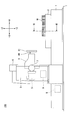
- FIG. 1 is a side view of a surface grinding machine 100 according to an embodiment of the present invention
- FIG. 2 is a top view thereof.
- the surface grinding machine 100 mainly includes a main body bed 1, an X-axis table 2, a horizontal axis grinding wheel column 3, a horizontal axis grinding wheel head 4, a grinding wheel head rotating motor 5, a grinding wheel head vertical feed motor 6, and a grinding wheel head left and right feeding.
- the main body bed 1 is a pedestal that supports an X-axis table 2 as a movable table so as to be reciprocally movable in the X-axis direction.
- the main body bed 1 has rail grooves 1AL and 1AR for receiving guide rails protruding from the lower surface of the X-axis table 2 on its upper surface.
- the X-axis table 2 is a movable table that can slide on the main body bed 1 in the X-axis direction, and supports the workpiece (workpiece) W on its upper surface.
- the horizontal axis grinding wheel column 3 is a device that supports the horizontal axis grinding wheel head 4 so as to be movable in the vertical direction (Z-axis direction) and the horizontal direction (Y-axis direction).
- the horizontal axis grinding wheel head 4 is a grinding wheel head having a grinding wheel shaft 40.
- a grinding wheel 41 is attached to the tip of the grinding wheel shaft 40.
- the grinding wheel head rotating motor 5 is a motor that rotates the grinding wheel shaft 40 of the horizontal grinding wheel head 4, and for example, a servo motor is used.
- the grinding wheel head vertical feed motor 6 is a motor that drives a grinding wheel head vertical movement mechanism for moving the horizontal grinding wheel head 4 in the vertical direction (Z-axis direction).
- the grinding wheel head vertical feed motor 6 is a servo motor for rotating a ball screw shaft or a ball screw nut in a ball screw mechanism that moves the horizontal grinding wheel head 4 in the Z-axis direction.
- the grinding wheel head left / right feeding motor 7 is a motor that drives a grinding wheel head left / right movement mechanism for moving the horizontal axis grinding wheel head 4 in the left / right direction (Y-axis direction).
- the grinding wheel head left / right feeding motor 7 is a servo motor for rotating a ball screw shaft or a ball screw nut in a ball screw mechanism that moves the horizontal grinding wheel head 4 in the Y-axis direction.
- the vertical movement mechanism and the horizontal movement mechanism may be other mechanisms such as a rack and pinion mechanism.
- the table driving motor 8 is a motor that drives a table moving mechanism for moving the X-axis table 2 in the X-axis direction.
- the table driving motor 8 is a servo motor for rotating a bidirectional hydraulic pump constituting a table moving mechanism that is a closed circuit hydraulic system.
- the control device 9 is a device that controls the movement of the surface grinding machine 100, and is, for example, a computer including a CPU, a RAM, a ROM, and the like.
- control device 9 controls the table driving motor 8 to move the workpiece W on the X-axis table 2 to a predetermined position. Further, the control device 9 controls the grinding wheel head vertical feed motor 6 and the grinding wheel head lateral feed motor 7 to move the horizontal axis grinding wheel head 4 to a predetermined position.
- control device 9 controls the grindstone head rotating motor 5 to start the rotation of the horizontal axis grindstone head 4, and controls the table driving motor 8 to move the X-axis table 2 in the + X direction.
- the grinding wheel 41 is brought into contact with the workpiece W to start the first grinding process.
- the control device 9 moves the X-axis table 2 to -X. Move it back to the original position. At that time, the control device 9 may raise the horizontal axis grinding wheel head 4 by the grinding wheel head vertical feed motor 6. This is to prevent the horizontal axis grinding wheel head 4 from coming into contact with the workpiece W when the X-axis table 2 is returned to its original position. At this time, the control device 9 may temporarily stop the grindstone head rotating motor 5.
- control device 9 rotates the horizontal axis grinding wheel head 4 by the grinding wheel head rotating motor 5 and lowers the horizontal axis grinding wheel head 4 by the grinding wheel head vertical feed motor 6. Then, the control device 9 controls the table driving motor 8 to move the X-axis table 2 in the + X direction, brings the grinding wheel 41 into contact with the workpiece W, and starts the second grinding process.
- the controller 9 performs grinding of the workpiece W by repeating the above-described movement.
- the control device 9 may perform grinding by bringing the grinding wheel 41 into contact with the workpiece W when moving the X-axis table in the ⁇ X direction.
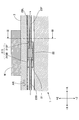
- FIGS. 3 is a front sectional view of the vertical plane including the alternate long and short dash line in each of FIGS. 1 and 2 as viewed from the direction indicated by arrow III
- FIG. 4 is the alternate long and two short dashes line in each of FIGS. It is the sectional side view which looked at the vertical plane containing No. from the direction shown by arrow IV.
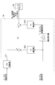
- FIG. 5 is a schematic diagram illustrating a configuration example of the table moving mechanism 20.
- illustration of the main body bed 1 is abbreviate
- the table moving mechanism 20 is a mechanism that reciprocates the X-axis table 2 in the X-axis direction, and mainly includes a cylinder 21, a piston 22, a first shaft 23F, a second shaft 23B, and both. It is composed of a closed circuit hydraulic system including a directional hydraulic pump 24.
- the cylinder 21 is fixed to the lower surface of the X-axis table 2 and moves on the main body bed 1 along the X-axis table 2 in the X-axis direction.
- the cylinder 21 includes a pressure chamber 21S (see FIG. 4) inside, and receives the piston 22 in the pressure chamber 21S so that the piston 22 can slide relative to the inner wall of the pressure chamber 21S.
- the pressure chamber 21 ⁇ / b> S is separated into a first pressure chamber 21 ⁇ / b> SF and a second pressure chamber 21 ⁇ / b> SB by the piston 22.
- the first shaft 23F is a cylindrical member having one end fixed to the surface on the + X side of the piston 22 and the other end fixed to an external stationary object 23Fa.
- the second shaft 23B is a cylindrical member having one end fixed to the ⁇ X side surface of the piston 22 and the other end fixed to the external stationary object 23Ba.
- the stationary objects 23Fa and 23Ba may be any object that can hold the cylinder 21, the first shaft 23F, and the second shaft 23B stationary when the X-axis table 2 is moved. May be.
- the piston 22 is a disk member accommodated in the pressure chamber 21S so that it can move relative to the inner wall of the pressure chamber 21S within the pressure chamber 21S of the cylinder 21. Further, the surface of the piston 22 on the + X side is connected to the first shaft 23F, and the surface on the ⁇ X side is connected to the first shaft 23F.
- the cylinder 21 can reciprocate with respect to the main body bed 1 together with the X-axis table 2, whereas the first shaft 23F, the second shaft 23B, and the piston 22 are attached to the main body bed 1. It arrange
- the X-axis table 2 includes two V-shaped guide rails 2BL and 2BR protruding from the lower surface in the ⁇ Z direction. Further, the X-axis table 2 is supported by the main body bed 1 so as to reciprocate in the X-axis direction on the main body bed 1 using a hydrostatic bearing mechanism, a dynamic pressure bearing mechanism, or a combination thereof or other bearing mechanisms. Is done. Note that the shape of the guide rail is not necessarily V-shaped.
- the reciprocation of the X-axis table 2 in the X-axis direction is controlled by a bidirectional hydraulic pump 24 driven by the table driving motor 8.
- a bidirectional hydraulic pump 24 driven by the table driving motor 8.
- the hydraulic oil discharged from the second port 24B of the bidirectional hydraulic pump 24 is shown.
- the hydraulic oil in the first pressure chamber 21SF of the cylinder 21 reaches the first port 24F of the bidirectional hydraulic pump 24 through the first shaft 23F.
- the volume of the second pressure chamber 21SB increases, the volume of the first pressure chamber 21SF decreases, and the X-axis table 2 is moved in the ⁇ X direction.
- the bidirectional hydraulic pump 24 is rotationally driven by the table driving motor 8, and the hydraulic fluid having a flow rate corresponding to the rotational direction and the rotational speed of the table driving motor 8 is supplied to the first port 24 ⁇ / b> F or the second. Discharge from port 24B.
- the table driving motor 8 is driven according to the current supplied by the motor driver 8A.
- the motor driver 8A receives the motor rotation command or torque command from the main controller 9A of the controller 9 and the table drive motor 8 according to the motor rotation command or torque command from the thrust compensator 9B as a sub controller.
- the motor driver 8A may supply a current to the table driving motor 8 in accordance with a motor rotation speed command from the main controller 9A and a motor rotation speed command from the thrust compensator 9B.
- a current may be supplied to the table driving motor 8 in accordance with the torque command from and the torque command from the thrust compensator 9B.
- the motor driver 8A may supply current to the table driving motor 8 in accordance with the motor rotation speed command from the main controller 9A and the torque command from the thrust compensator 9B.
- a current may be supplied to the table driving motor 8 in accordance with the torque command and the motor rotational speed command from the thrust compensator 9B.
- the main controller 9A outputs a motor rotation speed command or a torque command to the motor driver 8A so that the cylinder 21 obtains a force for moving the X-axis table 2.
- the main controller 9A for example, sends a motor rotation speed command to the motor driver 8A so that the cylinder 21 obtains a force in the desired movement direction having the same magnitude as the inertial force of the X-axis table 2.
- a torque command is output.
- the force in the desired movement direction having the same magnitude as the inertial force of the X-axis table 2 is obtained by multiplying the mass of the X-axis table 2 (including the workpiece W) by the acceleration of the X-axis table 2. It is power.
- the main controller 9A controls the rotational speed of the bidirectional hydraulic pump 24.
- the main controller 9A generates a motor rotation speed command or a torque command based on various command values from the control device 9 and various sensor outputs from various sensors.
- the various command values are command values generated by the control device 9 in response to an operator's input or the like, and include a table position command, a table speed command, a table acceleration command, a table drive motor rotational speed command (motor Speed command).
- the various sensor outputs include outputs from the displacement sensor 30, the first cylinder pressure sensor 31F, the second cylinder pressure sensor 31B, the rotation speed sensor 32, and the like.
- the displacement sensor 30 is a displacement sensor that detects the displacement of the X-axis table 2.
- the displacement sensor 30 detects a linear displacement with respect to a predetermined reference position of the X-axis table 2, and outputs the detection result to the control device 9.
- a linear scale is used as the displacement sensor 30.
- the first cylinder pressure sensor 31F is a sensor that detects the pressure of the first pressure chamber 21SF in the cylinder 21, for example, in a pipe line that connects the first shaft 23F and the first port 24F of the bidirectional hydraulic pump 24. The pressure of the hydraulic oil is detected, and the detection result is output to the control device 9.
- the second cylinder pressure sensor 31B is a sensor that detects the pressure of the second pressure chamber 21SB in the cylinder 21, and is, for example, a pipe that connects the second shaft 23B and the second port 24B of the bidirectional hydraulic pump 24. The pressure of hydraulic oil in the road is detected, and the detection result is output to the control device 9.
- the first cylinder pressure sensor 31F and the second cylinder pressure sensor 31B may be attached to the first pressure chamber 21SF and the second pressure chamber 21SB, or may be attached to the first shaft 23F and the second shaft 23B. .
- the rotation speed sensor 32 is a sensor that detects the rotation of the table driving motor 8.
- the rotation speed sensor 32 detects the rotation direction and the rotation angle of the table driving motor 8, and outputs the detection result to the control device 9.
- a resolver is used as the rotation angle sensor 32.
- the thrust compensator 9B is a functional element that compensates for a force that is offset by a force that hinders the movement of the X-axis table 2 among the thrusts for moving the X-axis table 2.
- the thrust compensator 9 ⁇ / b> B is a force (hereinafter referred to as “preload force”) for canceling a movement drag, which is a force excluding the inertial force of the X-axis table 2, among the forces that hinder the movement of the X-axis table 2.
- the motor rotation number command or the torque command is output to the motor driver 8A so that the cylinder 21 obtains.
- the thrust compensator 9B applies to the motor driver 8A so that the cylinder 21 obtains a preload force that has the maximum static frictional force of the X-axis table 2 and faces the desired moving direction.
- Output a motor rotation speed command or torque command.
- the moving drag includes, for example, a grinding reaction force by the surface grinder 100 in addition to the frictional force.
- the thrust compensator 9B generates a motor rotation speed command or a torque command based on various command values from the control device 9 and various sensor outputs from various sensors.
- the various command values are command values generated by the control device 9 in response to an operator input or the like, and include at least the value of the compensation command.
- the various sensor outputs include outputs of the displacement sensor 30, the first cylinder pressure sensor 31F, the second cylinder pressure sensor 31B, the rotation speed sensor 32, a torque detector (not shown), and the like.
- the value of the compensation command is a value determined by the control device 9 as a compensation value determining unit, for example, a value representing a preload force.
- the control device 9 determines the value of the compensation command based on the output of the sensor. Further, the control device 9 may prepare a reference table or a function for associating the position and speed of the X-axis table 2, the differential pressure between the pressure chambers of the cylinder 21, and the value of the compensation command for the frictional force in advance. Good. In this case, the control device 9 determines the value of the compensation command using a reference table or a function from the table speed command or the table position or table speed acquired based on various sensor outputs. As a result, the control device 9 can generate the preload force at an earlier stage and can smoothly start the movement of the X-axis table 2.
- control device 9 when the control device 9 includes a sensor for measuring a grinding reaction force that is a movement drag, the control device 9 may determine the value of the compensation command based on the output of the sensor. Further, the control device 9 may prepare in advance a reference table or a function for associating the grinding conditions such as the grinding depth and the rotational speed of the grindstone shaft 40 with the value of the compensation command for the grinding reaction force. In this case, the control device 9 determines the value of the compensation command from the current grinding condition using a reference table or a function. As a result, the control device 9 can generate the preload force at an earlier stage and can smoothly start the movement of the X-axis table 2.
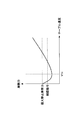
- FIG. 6 is a diagram showing the relationship between the value of the compensation command and the frictional force.
- the movement speed (table speed) of the X-axis table 2 is arranged on the horizontal axis, and the frictional force is arranged on the vertical axis.
- the frictional force of the X-axis table 2 is at the maximum static frictional force when the table speed is 0, and decreases as the table speed increases when the table speed is equal to or lower than the predetermined speed VTH .
- the table speed exceeds the predetermined speed VTH , the table speed increases as the table speed increases.
- the control device 9 changes the value of the compensation command according to the increase in the table speed, for example, along the transition of the frictional force. Further, the control device 9 may adopt a constant value equal to or less than the maximum static friction force (for example, 90% of the maximum static friction force) as the value of the compensation command regardless of the change in the table speed.
- the maximum static friction force for example, 90% of the maximum static friction force
- control device 9 may set the value of the compensation command to zero when the table speed exceeds the predetermined speed VTH . This is because the additional control by the thrust compensator 9B is executed only when the table speed is relatively low and the control by the main controller 9A is relatively unstable. Another reason is to simplify the control contents when the table speed is relatively high and the control by the main controller 9A is stable.
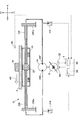
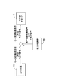
- FIG. 7 is a diagram showing a flow of control when the surface grinding machine 100 moves the X-axis table 2.
- the main controller 9 ⁇ / b> A acquires various command values including at least one of a table position command, a table speed command, a table acceleration command, and a motor speed command from the control device 9.
- the thrust compensator 9B obtains various command values including at least a compensation command from the control device 9.
- the various sensor outputs acquired by the main controller 9A are at least one of a table position signal output from the displacement sensor 30, a cylinder pressure signal output from the cylinder pressure sensors 31F and 31B, and a motor rotation angle signal output from the rotation angle sensor 32. including.
- the main controller 9A acquires a table position signal output from the displacement sensor 30.
- the main controller 9A acquires a motor rotation angle signal output from the rotation speed sensor 32.
- the thrust compensator 9B for example, when performing feedback control of the preload force, the first cylinder pressure signal output by the first cylinder pressure sensor 31F and the second cylinder pressure sensor 31B output. Get the cylinder pressure signal.
- the thrust compensator 9B monitors the thrust currently generated by the table moving mechanism 20 based on the differential pressure between the pressure chambers of the cylinder 21, and outputs the motor rotation speed command or the motor speed command output to the motor driver 8A. Determine the torque command value.
- the thrust compensator 9B may not acquire the sensor output.
- the main controller 9A and the thrust compensator 9B generate a motor rotation speed command or torque command based on the acquired various command values and various sensor outputs, respectively, and the generated motor rotation speed command or torque command is output to the motor driver. Output to 8A.
- the motor driver 8A supplies a current to the table driving motor 8 in accordance with a motor rotation speed command or a torque command from the main controller 9A and the thrust compensator 9B.
- s represents a Laplace operator
- a cyl represents the pressure receiving area of the piston 22
- V cyl represents the volume of the pressure chamber 21S
- M represents the mass of the X-axis table 2
- B represents the X-axis table 2
- K oil The viscous friction coefficient of the hydraulic oil is represented by K oil and the bulk elastic modulus of the hydraulic oil is represented.
- Flow rate Q is proportional to the motor rotation speed omega m of the table drive motor 8, if put the displacement volume per unit rotation speed and W P, the transfer function from the motor rotation speed omega m up table velocity v is less (2)
- ⁇ n and ⁇ n are the natural frequency and damping coefficient of the X-axis table 2, respectively, and are expressed by the following equations (3) and (4).
- K HST is a gain obtained by the closed circuit hydraulic system and is expressed by the following equation (5).
- the damping coefficient ⁇ n is a coefficient representing the damping property of the vibration of the X-axis table 2, and in the case of ⁇ n ⁇ 1, it represents that the vibration is damped in a shorter time as the value is closer to 1. .
- the transfer function from the speed command v dir to the table speed v is expressed by the following expression (6) based on the above expression (2).
- ⁇ c and ⁇ c are a control natural frequency and a control damping coefficient of the X-axis table 2 when the speed and acceleration of the X-axis table 2 are fed back, respectively, and the following equations (7), It is represented by (8).
- K v and K a are a speed feedback gain and an acceleration feedback gain, respectively, and are expressed by the following equations (9) and (10).
- the acceleration feedback gain K a can determine the acceleration feedback gain K a according to the value of the desired control damping coefficients zeta c, i.e., can be realized the value of the desired control damping coefficients zeta c by adjusting the acceleration feedback gain K a Means.
- the main controller 9A acquires a table position command, a table speed command, and a table position signal, and outputs a motor rotation speed command or a torque command to the motor driver 8A.
- the main controller 9A first subtracts a value PL represented by a table position signal from the displacement sensor 30 from a value represented by a table position command from the control device 9 according to a proportional control law, and obtains a predetermined gain. multiplied by K p deriving a first control value V1 with.
- the main controller 9A may use a proportional-integral control law instead of the proportional control law.
- the main controller 9A adds a value obtained by subtracting the value PL from the value represented by the table position command and a value obtained by dividing the integral value of the subtracted value by a predetermined time constant, and then adds a predetermined value.
- the first control value V1 may be derived by multiplying the gain Kp.
- the main controller 9A adds a speed feedforward value VFF obtained by multiplying the value represented by the table speed command from the control device 9 by the speed feedforward gain Kvff and the first control value V1. Then, the main controller 9A from the value after addition (V1 + VFF), by subtracting the speed feedback value VFB obtained by multiplying the velocity feedback gain K v table position signal to a value represented by the table speed signal obtained by the pseudo-differential
- V1 + VFF the speed feedforward value obtained by multiplying the value represented by the table speed command from the control device 9 by the speed feedforward gain Kvff and the first control value V1. Then, the main controller 9A from the value after addition (V1 + VFF), by subtracting the speed feedback value VFB obtained by multiplying the velocity feedback gain K v table position signal to a value represented by the table speed signal obtained by the pseudo-differential
- the second control value V2 is derived.
- the main controller 9A obtains an acceleration feedback gain from the second control value V2 to a value represented by a table acceleration signal obtained by pseudo-differentiating the table speed signal, that is, obtained by second-order pseudo-differentiating the table position signal. by subtracting the acceleration feedback value AFB multiplied by K a, derive motor rotational speed command or torque command.
- the main controller 9A adds an acceleration feedforward value AFF (not shown) obtained by multiplying the value represented by the table acceleration command from the control device 9 by the acceleration feedforward gain Kaff and the second control value V2. Then, the motor feedback command or torque command may be derived by subtracting the acceleration feedback value AFB.
- the main controller 9A may omit the calculation of the speed feedback value VFB and the subtraction of the speed feedback value VFB from the total value of the first control value V1 and the speed feedforward value VFF.
- the main controller 9A shown in FIG. 8 adjusts the acceleration feedback gain K a under the control model having the transfer function expressed by the equation (6), thereby obtaining a desired control damping coefficient ⁇ c. Can be realized.
- the surface grinding machine 100 including the main controller 9A shown in FIG. 8 can quickly attenuate the vibration of the X-axis table 2 that occurs when the X-axis table 2 is accelerated or decelerated.
- the main controller 9A acquires the first cylinder pressure signal and the second cylinder pressure signal from the first cylinder pressure sensor 31F and the second cylinder pressure sensor 31B instead of the table position signal. This is different from the case of FIG. That is, it differs from the control of FIG. 8 in which the table acceleration signal obtained by second-order differentiation of the table position signal is fed back in that the table acceleration signal derived from the pressure difference between the pressure chambers is fed back.
- the main controller 9A differs from the control of FIG. 8 in that the motor rotational speed command or the torque command is derived based on the speed feedforward value VFF without deriving the first control value V1 based on the table position command. .
- the main controller 9A first subtracts the acceleration feedback value AFB from the speed feedforward value VFF obtained by multiplying the value represented by the table speed command from the control device 9 by the speed feedforward gain Kvff , Deriving motor rotation speed command or torque command.
- the main controller 9A derives the acceleration feedback value AFB based on the first cylinder pressure signal and the second cylinder pressure signal.
- the main controller 9A derives the difference between the first cylinder pressure signal and the second cylinder pressure signal, and applies a low-pass filter and a high-pass filter to the derived value.
- the low-pass filter is a functional element for removing noise included in the difference
- the high-pass filter is a functional element for removing the influence of the frictional force included in the difference.
- the signal after applying the low-pass filter and the high-pass filter has, for example, a frequency of about 1/3 to 5 times the natural frequency of the X-axis table 2.
- the main controller 9A multiplies the differential pressure signal by A cyl / M to obtain a table acceleration signal. That is, the main controller 9A multiplies the value represented by the differential pressure signal by the pressure receiving area A cyl of the piston 22 based on the equation of motion to derive the driving force by the bidirectional hydraulic pump 24, and calculates the driving force by the X-axis table. Divide by the mass M of 2 to derive the acceleration of the X-axis table 2. It should be noted that the mass M used when the velocity feedback gain is determined by the equation (9), the acceleration feedback gain is determined by the equation (10), and the acceleration of the X-axis table 2 is derived from the differential pressure signal, May vary depending on mass. In this case, instead of the actual mass, the nominal mass may be used as the value of the mass M. It is desirable to use the maximum mass of the workpiece W that can be mounted on the X-axis table 2 as the nominal mass.
- the main controller 9A derives acceleration feedback value AFB by multiplying the acceleration feedback gain K a to the value table acceleration signal represents.
- the main controller 9 ⁇ / b> A has an acceleration feedforward value AFF (not shown) obtained by multiplying the value represented by the table acceleration command from the control device 9 by the acceleration feedforward gain K aff .
- the motor feedback command AFB may be derived by subtracting the acceleration feedback value AFB.
- the main controller 9A shown in FIG. 9 does not acquire the cylinder pressure signal from each of the first cylinder pressure sensor 31F and the second cylinder pressure sensor 31B, but instead of the first pressure chamber 21SF and the second pressure chamber 21SB.
- a differential pressure signal may be acquired from a differential pressure sensor (not shown) that detects a differential pressure therebetween.
- the main controller 9A shown in Figure 9 similarly to the case shown in FIG. 8, under the control model having a transfer function represented by the formula (6), by adjusting the acceleration feedback gain K a
- the desired control damping coefficient ⁇ c can be realized.
- the surface grinding machine 100 including the main controller 9A shown in FIG. 9 can quickly attenuate the vibration of the X-axis table 2 that occurs when the X-axis table 2 is accelerated or decelerated.
- the main controller 9A is different from the case of FIG. 8 in that it obtains a table speed signal from a table speed sensor (not shown) such as a tachometer instead of the table position signal. . That is, it differs from the control of FIG. 8 in which the table acceleration signal obtained by second-order differentiation of the table position signal is fed back in that the table acceleration signal obtained by first-order differentiation of the table speed signal is fed back.
- a table speed sensor such as a tachometer
- the main controller 9A differs from the control of FIG. 8 in that the motor rotational speed command or the torque command is derived based on the speed feedforward value VFF without deriving the first control value V1 based on the table position command. .
- the main controller 9A first derives a speed feedforward value VFF obtained by multiplying the value represented by the table speed command from the control device 9 by the speed feedforward gain Kvff .
- the main controller 9A from the speed feedforward value VFF, by subtracting the speed feedback value VFB obtained by multiplying the velocity feedback gain K v to the value table speed signal represents, derive a second control value V2.
- the main controller 9A from the second control value V2, by subtracting the acceleration feedback value AFB obtained by multiplying the acceleration feedback gain K a to the value represented by the table acceleration signal obtained by first-order quasi-differentiation of the table speed signal
- the motor rotational speed command or torque command is derived.
- the main controller 9A also uses the value AFF (not shown) obtained by multiplying the value represented by the table acceleration command from the control device 9 by the acceleration feedforward gain K aff , and the second control.
- the motor rotation speed command or torque command may be derived by adding the value V2 and subtracting the acceleration feedback value AFB.
- the main controller 9A may omit calculation of the speed feedback value VFB and subtraction of the speed feedback value VFB from the speed feedforward value VFF.
- the main controller 9A shown in FIG. 10 similarly to the case shown in FIG. 8, under the control model having a transfer function represented by the formula (6), by adjusting the acceleration feedback gain K a
- the desired control damping coefficient ⁇ c can be realized.
- the surface grinding machine 100 including the main controller 9A shown in FIG. 10 can quickly attenuate the vibration of the X-axis table 2 that occurs when the X-axis table 2 is accelerated or decelerated.
- the main controller 9A acquires a table acceleration signal from a table acceleration sensor (not shown) instead of the table position signal. That is, it differs from the control of FIG. 8 in which the table acceleration signal obtained by second-order differentiation of the table position signal is fed back in that the table acceleration signal obtained directly from the table acceleration sensor is fed back.
- the main controller 9A differs from the control of FIG. 8 in that the motor rotational speed command or the torque command is derived based on the speed feedforward value VFF without deriving the first control value V1 based on the table position command. .
- the main controller 9A first derives a speed feedforward value VFF obtained by multiplying the value represented by the table speed command from the control device 9 by the speed feedforward gain Kvff .
- the main controller 9A subtracts the acceleration feedback value AFB from the speed feedforward value VFF to derive a motor rotation speed command or a torque command.
- the main controller 9 ⁇ / b> A has an acceleration feedforward value AFF (not shown) obtained by multiplying the value represented by the table acceleration command from the control device 9 by the acceleration feedforward gain Kaff .
- the motor feedback command AFB may be derived by subtracting the acceleration feedback value AFB.
- the main controller 9A shown in FIG. 11 similarly to the case shown in FIG. 8, under the control model having a transfer function represented by the formula (6), by adjusting the acceleration feedback gain K a
- the desired control damping coefficient ⁇ c can be realized.
- the surface grinding machine 100 including the main controller 9A of FIG. 11 can attenuate the vibration of the X-axis table 2 that occurs when the X-axis table 2 is accelerated or decelerated at an early stage.
- the main controller 9A may omit obtaining either the table position command or the table speed command.
- the main controller 9A may omit feedback control based on part or all of the table position, table speed, and table acceleration, and feed based on part or all of the table position, table speed, and table acceleration.
- the forward control may be omitted.
- the main controller 9A shown in FIGS. 9 to 11 cancels the difference between the actual table position value and the value represented by the table position command, or represents the actual table speed value and the table speed command.
- the motor rotational speed command or torque command may be derived so as to cancel the difference from the value.
- the main controller 9A shown in FIGS. 9 to 11 speeds the first control signal V1 calculated based on the value represented by the table position command and the value PL represented by the table position signal, as in FIG. You may make it add to feedforward value VFF.
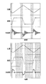
- FIG. 12 is a diagram showing temporal transitions of the table position, table speed, and table acceleration of the X-axis table 2.
- the upper diagram of FIG. 12 shows the transition when the acceleration feedback value AFB is not used, and the lower diagram of FIG. Shows the transition when the acceleration feedback value AFB is used. Further, the time transition of the table position is common in the upper diagram of FIG. 12 and the lower diagram of FIG.
- the hatched area in FIG. 12 represents the time from when the table acceleration value becomes less than the predetermined value and the table speed is settled until the table acceleration value becomes equal to or greater than the predetermined value and the table speed fluctuates.
- the table acceleration value becomes less than the predetermined value after the table acceleration value becomes equal to or greater than the predetermined value and the table speed becomes less than the predetermined value until the table speed is stabilized.
- the hatched area is referred to as a table speed stable period
- the non-hatched area (white area) is referred to as a table speed fluctuation period.
- the table speed fluctuation period when the acceleration feedback value AFB is used (white area in the lower diagram of FIG. 12) is the table speed fluctuation period when the acceleration feedback value AFB is not used (white area of the upper diagram of FIG. 12). Shorter than (region). Further, the table speed stable period when the acceleration feedback value AFB is used (hatched area in the lower diagram of FIG. 12) is compared with the table speed stable period when the acceleration feedback value AFB is not used (hatched area in the upper diagram of FIG. 12). long. This means that the portion that can be used for grinding the workpiece W in one stroke of the X-axis table 2 becomes longer. Moreover, it means that the allowable maximum length in the X-axis direction of the workpiece W placed on the X-axis table 2 can be further increased. That is, all of grinding efficiency, energy efficiency, and applicability are improved.
- the surface grinding machine 100 provided with the main controller 9A attenuates the vibration of the X-axis table 2 caused by the acceleration / deceleration of the X-axis table 2 at an early stage, and the grinding efficiency, energy efficiency, and application Can be improved.
- the operator of the surface grinder 100 with a master controller. 9A by appropriately adjusting the acceleration feedback gain K a, it is possible to shorten the settling time of the table velocity in the X-axis table 2.
- the operator by adjusting the acceleration feedback gain K a to approach the value of the control damping coefficients zeta c to 1, reduced or that the table velocity in the X-axis table 2 overshoot the value of the speed command Can be prevented.
- the thrust compensator 9B acquires a compensation command from the control device 9, and outputs a motor rotation speed command or a torque command to the motor driver 8A.
- the thrust compensator 9B is a value F 0 representative of the compensation command from the control unit 9, to obtain the value of the torque command by multiplying the W P / A cyl.
- W P is a displacement volume per unit rotation of the bidirectional hydraulic pump 24
- a cyl is the pressure receiving area of the piston 22. Therefore, F 0 / A cyl represents the differential pressure DP 0 between the pressure chamber of the cylinder 21, DP 0 ⁇ W P represents the torque due to the bidirectional hydraulic pump 24.
- the thrust compensator 9B is over the designated pressure difference DP 0 necessary for generating the preloading force, derive the value of the torque required to generate the differential pressure DP 0, derived was The value is output as a torque command value to the motor driver 8A.
- the thrust compensator 9B acquires a table acceleration command from the control device 9, and the first cylinder pressure signal and the second cylinder pressure from the first cylinder pressure sensor 31F and the second cylinder pressure sensor 31B. It differs from the case of FIG. 13 in that a signal is acquired.
- the thrust compensator 9B derives the inertial force of the X-axis table 2 by multiplying the value of the table acceleration command by the mass M of the X-axis table 2.
- the thrust compensator 9B multiplies the difference between the first cylinder pressure signal and the second cylinder pressure signal by the pressure receiving area A cyl of the piston 22 to derive the thrust by the bidirectional hydraulic pump 24.
- the thrust compensator 9B adds the preload force indicated by the value of the compensation command and the inertial force of the X-axis table 2.
- the preload force is added as having the same sign as the inertial force of the X-axis table 2 when the X-axis table 2 is accelerated. That is, the preload force is positive when the inertial force is positive, and the preload force is negative when the inertial force is negative.
- the preload force is added as having an opposite sign to the inertial force of the X-axis table 2.
- the preload force is a positive value when the inertial force is a negative value
- the preload force is a negative value when the inertial force is a positive value.
- the value calculated in this way means a force that hinders the movement of the X-axis table 2.
- the preload force is a reverse force having the same magnitude as the movement drag, which is a force obtained by removing the inertial force of the X-axis table 2 from the force that hinders the movement of the X-axis table 2.
- the thrust compensator 9B can eliminate the influence of the movement drag
- the main controller 9A controls the bidirectional hydraulic pump 24 so that the X-axis table 2 accelerates and decelerates according to various command values. can do.
- the thrust compensator 9B subtracts the thrust by the bidirectional hydraulic pump 24 from the force that hinders the movement of the X-axis table 2 calculated as described above, and derives the control value V3.
- the thrust compensator 9B multiplies the control value V3 by a predetermined compensation gain K comp to derive a motor rotation speed command or torque command for compensating for the thrust canceled by the movement drag.
- the thrust compensator 9B determines the direction in which the X-axis table 2 is to be moved next.
- the control value V3 is derived by subtracting the thrust from the bidirectional hydraulic pump 24 from the preload force in the positive direction of the preload force. If the direction in which the X-axis table 2 is to be moved next is not yet determined, the direction in which the X-axis table 2 was moved last time may be the positive direction of the preload force.
- the X-axis table 2 When grinding a surface perpendicular to the X-axis, the X-axis table 2 is set to a predetermined value in order to repeat the grinding process at a predetermined grinding depth for a plurality of times in order to achieve a desired grinding depth. This is because it may be moved intermittently in one direction depending on the grinding depth.
- the thrust compensator 9B multiplies the control value V3 by a predetermined compensation gain K comp to derive a motor rotational speed command or torque command for compensating for the thrust canceled by the movement drag. That is, the thrust by the bidirectional hydraulic pump 24 is made to be a preload force.
- the thrust compensator 9B determines the value of the motor rotation speed command or the torque command so that the differential pressure between the pressure chambers of the cylinder 21 becomes a differential pressure necessary to generate a desired preload force.
- the determined value is output to the motor driver 8A. That is, the thrust compensator 9B outputs the value of the motor rotation speed command or the torque command determined based on the feedback control of the differential pressure between the pressure chambers of the cylinder 21 to the motor driver 8A.
- the thrust compensator 9B may obtain the table acceleration signal by second-order differentiation of the table position signal output from the displacement sensor 30, instead of obtaining the table acceleration command from the control device 9.
- a table acceleration signal may be obtained by first-order differentiation of a table speed signal output from a table speed sensor (not shown) such as an tacho generator.
- the table acceleration signal may be obtained from an acceleration sensor (not shown). You may obtain it directly.
- the thrust compensator 9B may use a PI controller instead of a multiplier that multiplies the compensation gain K comp .
- the motor driver 8A receives the motor rotation speed command or the torque command output separately from the main controller 9A and the thrust compensator 9B, respectively.
- the present invention is not limited to this.
- the motor driver 8A receives the total value of the motor rotational speed command value output from the main controller 9A and the motor rotational speed command value output from the thrust compensator 9B. Also good.
- the motor driver 8A may receive the total value of the torque command value output from the main controller 9A and the torque command value output from the thrust compensator 9B.
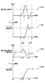
- FIG. 16 is a diagram showing a time transition of the thrust by the bidirectional hydraulic pump 24 and a time transition of the table speed of the X-axis table 2.
- F16A1 indicates a time transition of thrust when the thrust compensator 9B is not used
- F16B1 indicates a time transition of table speed when the thrust compensator 9B is not used
- F16A2 indicates the time transition of the thrust when the thrust compensator 9B is used
- F16B2 indicates the time transition of the table speed when the thrust compensator 9B is used.
- the thrust by the bidirectional hydraulic pump 24 starts to rise at time t1, as indicated by F16A1. This is because, for example, the operator inputs a movement command for the X-axis table 2 to the control device 9, and the control of the table driving motor 8 by the main controller 9A is started. Note that the table speed of the X-axis table 2 remains zero. This is because the thrust is less than the maximum static friction force.
- the X-axis table 2 starts to move.
- the table speed of the X-axis table 2 increases and overshoots exceeding the value of the table speed command. This is because the time between time t1 and time t2 is relatively long, and the rate of increase in the value of the motor rotation speed command or torque command by the main controller 9A is excessively large. That is, although the main controller 9A increases the value of the motor rotation speed command or the torque command, the time during which the table speed remains zero is relatively long. This tendency becomes more prominent as the time between time t1 and time t2 is longer.
- the thrust decreases rapidly and further increases in the opposite direction. This is because the main controller 9A sharply decreases the value of the motor rotation speed command or torque command in order to cancel the overshoot. As a result, the table speed undershoots below the value of the table speed command.
- the table speed converges to the value of the table speed command at time t3 while repeating such overshoot and undershoot.
- F16B1 shows a state in which overshoot and undershoot each occur once for the sake of clarity.
- the thrust by the bidirectional hydraulic pump 24 is input to the control device 9 at time t0, that is, the movement command of the X-axis table 2 by the operator. Before the rise begins. Then, the thrust by the bidirectional hydraulic pump 24 rises to the value of the compensation command. This is because the control of the table driving motor 8 for generating the preload force by the thrust compensator 9B is started. The value of the compensation command is determined so as to be equal to or less than the maximum static friction force. This is because the X-axis table 2 moves before the movement command by the operator is input to the control device 9 when the maximum static friction force is greater. For this reason, the table speed of the X-axis table 2 remains zero, but the X-axis table 2 becomes movable by applying a slight thrust.
- the thrust compensator 9B estimates the subsequent movement direction of the X-axis table 2 based on the current position of the X-axis table 2 and various information related to grinding. As a result, the thrust compensator 9B can generate a preload force in the estimated direction before the operator inputs a movement command for the X-axis table 2 to the control device 9.
- the thrust by the bidirectional hydraulic pump 24 exceeds the maximum static frictional force at time t2a, and the X-axis table 2 starts moving.
- the table speed of the X-axis table 2 increases relatively slowly as compared with the case of F16A1, and converges to the value of the table speed command at time t3a without causing overshoot and undershoot.
- the time between time t1 and time t2a is shorter by time D1
- the rate of increase in the value of the motor rotation speed command or torque command by the main controller 9A is excessive. It is because it does not become big. That is, because the main controller 9A increases the value of the motor rotation speed command or torque command, the time during which the table speed remains zero is short.
- the time until the table speed is settled is shortened by a time D2 as compared with the case where the thrust compensator 9B is not used.
- the thrust compensator 9B compensates for the force that is canceled out by the movement drag if the absolute value of the table speed is less than the predetermined speed VTH .
- the surface grinding machine 100 including the thrust compensator 9B can start the movement of the X-axis table 2 early and smoothly. Further, it is possible to suppress or prevent the table speed overshoot and undershoot that occur immediately after the movement of the X-axis table 2 is started.
- the surface grinding machine 100 employs the horizontal axis grinding wheel head 4, but a vertical axis grinding wheel head may be employed.
- the grindstone head may include a tiltable shaft.
- the main controller 9A and the thrust compensator 9B control the table driving motor 8 that drives the bidirectional hydraulic pump constituting the table moving mechanism of the surface grinding machine 100.
- the present invention is not limited to this.
- the main controller 9A and the thrust compensator 9B control a motor that drives a bidirectional hydraulic pump that constitutes a closed circuit hydraulic system that moves heavy objects, which is mounted on a construction machine, an injection molding machine, a machine tool, or the like. You may do.
- the thrust compensator 9B compensates for a force that is offset by excavation reaction force in the construction machine, cutting reaction force in the machine tool, and the like, among the forces generated by the motor.
- the closed circuit hydraulic system uses the pressure (hydraulic pressure) of hydraulic oil.
- the closed circuit hydraulic system may use, for example, a pressure (hydraulic pressure) of a liquid having low compressibility such as water instead of the hydraulic pressure.
- the main controller 9A controls the rotational speed of the bidirectional hydraulic pump 24 via the motor driver 8A and the table driving motor 8.
- the present invention is not limited to this.
- the main controller 9A may control the rotational speed of the bidirectional hydraulic pump 24 by an internal combustion engine instead of controlling the rotational speed of the bidirectional hydraulic pump 24 by the table driving motor 8.
Abstract
双方向油圧ポンプ24を含むテーブル移動機構20を用いてX軸テーブル2を移動させる平面研削盤100は、X軸テーブル2の位置又は速度を制御目標としてX軸テーブル2の移動を制御する制御装置9と、制御装置9からのテーブル位置指令又はテーブル速度指令に応じて、双方向油圧ポンプ24を制御する主制御器9Aと、X軸テーブル2の移動を妨げる力を打ち消すように双方向油圧ポンプ24を制御する推力補償器9Bとを備える。
Description
本発明は、平面研削盤に関し、より詳細には、被研削物を載せる可動テーブルを備えた平面研削盤に関する。
従来、双方向油圧ポンプ及び油圧シリンダを含む閉回路油圧システムを用いて可動テーブルを往復移動させる電気-油圧変換式駆動装置が知られている(例えば、特許文献1参照。)。
この装置は、可動テーブルの送り速度を検出するタコジェネレータの出力に基づいて、双方向油圧ポンプを駆動する電気サーボモータの回転速度を制御する。この構成により、開回路油圧システムのように作動油の流れを制御するバルブを配置する必要なく可動テーブルの送り速度を制御でき、エネルギ効率を向上させることができる。
しかしながら、特許文献1の電気-油圧変換式駆動装置は、可動テーブルの指令速度に基づいて電気サーボモータの回転速度を制御するのみである。そのため、油圧シリンダ内でピストンを摺動させる際に、油圧パッキン等のピストンシールと油圧シリンダの内壁との間に発生する摩擦力による制御性の悪化を防止できない。その結果、可動テーブルの移動を開始させる際の可動テーブルの動きを不安定にしてしまう。
上述の点に鑑み、本発明は、可動テーブルの移動を開始させる際の可動テーブルの動きを安定化させることができる平面研削盤を提供することを目的とする。
上述の目的を達成するために、本発明の実施例に係る平面研削盤は、双方向液圧ポンプを含む閉回路液圧システムを用いて可動テーブルを移動させる平面研削盤であって、前記可動テーブルの位置又は速度を制御目標として前記可動テーブルの移動を制御する制御装置と、前記制御装置からのテーブル位置指令又はテーブル速度指令に応じて、前記双方向液圧ポンプの回転数を制御する主制御器と、前記可動テーブルの移動を妨げる力を打ち消すように前記双方向液圧ポンプを制御する副制御器と、を備える。
上述の手段により、本発明は、可動テーブルの移動を開始させる際の可動テーブルの動きを安定化させることができる平面研削盤を提供することができる。
以下、図面を参照しつつ、本発明を実施するための最良の形態の説明を行う。
図1は、本発明の実施例に係る平面研削盤100の側面図であり、図2は、その上面図である。平面研削盤100は、主に、本体ベッド1、X軸テーブル2、横軸砥石用コラム3、横軸砥石ヘッド4、砥石ヘッド回転用モータ5、砥石ヘッド上下送り用モータ6、砥石ヘッド左右送り用モータ7、テーブル駆動用モータ8、及び制御装置9を含む。
本体ベッド1は、可動テーブルとしてのX軸テーブル2をX軸方向に往復移動可能に支持する台座である。具体的には、本体ベッド1は、X軸テーブル2の下面から突出するガイドレールを受け入れるレール溝1AL、1ARをその上面に有する。
X軸テーブル2は、本体ベッド1上をX軸方向に摺動可能な可動テーブルであり、その上面で被研削物(ワーク)Wを支持する。
横軸砥石用コラム3は、横軸砥石ヘッド4を上下方向(Z軸方向)及び左右方向(Y軸方向)に移動可能に支持する装置である。
横軸砥石ヘッド4は、砥石軸40を有する砥石ヘッドである。本実施例では、砥石軸40の先端には、砥石車41が取り付けられる。
砥石ヘッド回転用モータ5は、横軸砥石ヘッド4の砥石軸40を回転させるモータであり、例えば、サーボモータが用いられる。
砥石ヘッド上下送り用モータ6は、横軸砥石ヘッド4を上下方向(Z軸方向)に移動させるための砥石ヘッド上下移動機構を駆動するモータである。本実施例では、砥石ヘッド上下送り用モータ6は、横軸砥石ヘッド4をZ軸方向に移動させるボールねじ機構におけるボールねじ軸又はボールねじナットを回転させるためのサーボモータである。
砥石ヘッド左右送り用モータ7は、横軸砥石ヘッド4を左右方向(Y軸方向)に移動させるための砥石ヘッド左右移動機構を駆動するモータである。本実施例では、砥石ヘッド左右送り用モータ7は、横軸砥石ヘッド4をY軸方向に移動させるボールねじ機構におけるボールねじ軸又はボールねじナットを回転させるためのサーボモータである。
なお、上下移動機構及び左右移動機構は、ラックアンドピニオン機構等の他の機構であってもよい。
テーブル駆動用モータ8は、X軸テーブル2をX軸方向に移動させるためのテーブル移動機構を駆動するモータである。本実施例では、テーブル駆動用モータ8は、閉回路油圧システムであるテーブル移動機構を構成する双方向油圧ポンプを回転させるためのサーボモータである。
制御装置9は、平面研削盤100の動きを制御する装置であり、例えば、CPU、RAM、ROM等を備えたコンピュータである。
具体的には、制御装置9は、テーブル駆動用モータ8を制御してX軸テーブル2上のワークWを所定位置に移動させる。また、制御装置9は、砥石ヘッド上下送り用モータ6及び砥石ヘッド左右送り用モータ7を制御して横軸砥石ヘッド4を所定位置に移動させる。
その後、制御装置9は、砥石ヘッド回転用モータ5を制御して横軸砥石ヘッド4の回転を開始させ、且つ、テーブル駆動用モータ8を制御してX軸テーブル2を+X方向に移動させ、砥石車41をワークWに接触させて1回目の研削加工を開始する。
テーブル駆動用モータ8によりX軸テーブル2を+X方向の所定位置まで移動させると、すなわち砥石車41によるワークWに対する1回目の研削加工が終了すると、制御装置9は、X軸テーブル2を-X方向に移動させて元の位置に戻す。その際、制御装置9は、砥石ヘッド上下送り用モータ6により横軸砥石ヘッド4を上昇させてもよい。X軸テーブル2を元に戻すときに横軸砥石ヘッド4がワークWと接触しないようにするためである。このとき、制御装置9は、砥石ヘッド回転用モータ5を一旦停止させてもよい。
その後、制御装置9は、砥石ヘッド回転用モータ5により横軸砥石ヘッド4を回転させ、砥石ヘッド上下送り用モータ6により横軸砥石ヘッド4を下降させる。そして、制御装置9は、テーブル駆動用モータ8を制御してX軸テーブル2を+X方向に移動させ、砥石車41をワークWに接触させて2回目の研削加工を開始する。
上述の動きを繰り返すことによって、制御装置9は、ワークWの研削を実行する。なお、制御装置9は、X軸テーブルを-X方向に移動させる際に砥石車41をワークWに接触させて研削加工を行ってもよい。
次に、図3~図5を参照しながら、テーブル移動機構20について説明する。なお、図3は、図1及び図2のそれぞれにおける一点鎖線を含む鉛直面を矢印IIIで示す方向から見た正断面図であり、図4は、図2及び図3のそれぞれにおける二点鎖線を含む鉛直面を矢印IVで示す方向から見た側断面図である。図5は、テーブル移動機構20の構成例を示す概略図である。なお、図5では、明瞭化のため、本体ベッド1の図示を省略している。
図5に示すように、テーブル移動機構20は、X軸テーブル2をX軸方向に往復移動させる機構であり、主に、シリンダ21、ピストン22、第1軸23F、第2軸23B、及び双方向油圧ポンプ24を含む閉回路油圧システムで構成される。
シリンダ21は、X軸テーブル2の下面に固定され、X軸テーブル2と共に本体ベッド1上をX軸方向に移動する。また、シリンダ21は、内部に圧力室21S(図4参照。)を備え、ピストン22が圧力室21Sの内壁に対して相対的にスライドできるようにピストン22を圧力室21S内に受け入れる。なお、圧力室21Sは、図4に示すように、ピストン22によって、第1圧力室21SFと第2圧力室21SBに分離される。
第1軸23Fは、一端がピストン22の+X側の面に固定され、他端が外部の静止物23Faに固定される円筒部材である。同様に、第2軸23Bは、一端がピストン22の-X側の面に固定され、他端が外部の静止物23Baに固定される円筒部材である。なお、静止物23Fa、23Baは、X軸テーブル2を移動させる場合にシリンダ21、第1軸23F、及び第2軸23Bを静止したまま保持できる物体であればよく、例えば、本体ベッド1であってもよい。
ピストン22は、シリンダ21の圧力室21S内で、圧力室21Sの内壁に対して相対移動できるように圧力室21S内に収容される円板部材である。また、ピストン22は、+X側の面が第1軸23Fに接続され、-X側の面が第1軸23Fに接続される。
このような構成により、シリンダ21は、X軸テーブル2と共に、本体ベッド1に対して往復移動可能であるのに対し、第1軸23F、第2軸23B、及びピストン22は、本体ベッド1に対して静止するように配置される。
X軸テーブル2は、図3に示すように、その下面から-Z方向に突出する2つのV字型のガイドレール2BL、2BRを備える。また、X軸テーブル2は、静圧軸受機構、動圧軸受機構、若しくはそれらの組み合わせ又はその他の軸受機構を用い、本体ベッド1上をX軸方向に往復移動できるように、本体ベッド1によって支持される。なお、ガイドレール形状は必ずしもV字型である必要はない。
また、X軸テーブル2のX軸方向の往復移動は、テーブル駆動用モータ8によって駆動される双方向油圧ポンプ24によって制御される。具体的には、図4及び図5に示すように、X軸テーブル2を矢印ARで示す方向(-X方向)に移動させる場合、双方向油圧ポンプ24の第2ポート24Bが吐出する作動油は、点線で示すように、第2軸23Bを通ってシリンダ21の第2圧力室21SBに流入する。一方で、シリンダ21の第1圧力室21SF内の作動油は、第1軸23Fを通って双方向油圧ポンプ24の第1ポート24Fに至る。その結果、第2圧力室21SBの体積が増大し、第1圧力室21SFの体積が減少して、X軸テーブル2は、-X方向に移動させられる。
図示は省略するが、X軸テーブル2を+X方向に移動させる場合には、双方向油圧ポンプ24の第1ポート24Fが吐出する作動油は、第1軸23Fを通ってシリンダ21の第1圧力室21SFに流入する。一方で、シリンダ21の第2圧力室21SB内の作動油は、第2軸23Bを通って双方向油圧ポンプ24の第2ポート24Bに至る。その結果、第1圧力室21SFの体積が増大し、第2圧力室21SBの体積が減少して、X軸テーブル2は、+X方向に移動させられる。
双方向油圧ポンプ24は、図5に示すように、テーブル駆動用モータ8によって回転駆動され、テーブル駆動用モータ8の回転方向及び回転数に応じた流量の作動油を第1ポート24F又は第2ポート24Bから吐出する。
テーブル駆動用モータ8は、モータドライバ8Aが供給する電流に応じて駆動される。モータドライバ8Aは、制御装置9の主制御器9Aからのモータ回転数指令又はトルク指令と副制御器としての推力補償器9Bからのモータ回転数指令又はトルク指令とに応じてテーブル駆動用モータ8に電流を供給する。例えば、モータドライバ8Aは、主制御器9Aからのモータ回転数指令と推力補償器9Bからのモータ回転数指令とに応じてテーブル駆動用モータ8に電流を供給してもよく、主制御器9Aからのトルク指令と推力補償器9Bからのトルク指令とに応じてテーブル駆動用モータ8に電流を供給してもよい。或いは、モータドライバ8Aは、主制御器9Aからのモータ回転数指令と推力補償器9Bからのトルク指令とに応じてテーブル駆動用モータ8に電流を供給してもよく、主制御器9Aからのトルク指令と推力補償器9Bからのモータ回転数指令とに応じてテーブル駆動用モータ8に電流を供給してもよい。
主制御器9Aは、X軸テーブル2を移動させるための力をシリンダ21が得るようにモータドライバ8Aに対してモータ回転数指令又はトルク指令を出力する。具体的には、主制御器9Aは、例えば、X軸テーブル2の慣性力と同じ大きさを持つ所望の移動方向を向く力をシリンダ21が得るようにモータドライバ8Aに対してモータ回転数指令又はトルク指令を出力する。なお、X軸テーブル2の慣性力と同じ大きさを持つ所望の移動方向を向く力は、X軸テーブル2(ワークWを含む。)の質量にX軸テーブル2の加速度を乗算して得られる力である。
また、主制御器9Aは、双方向油圧ポンプ24の回転数を制御する。例えば、主制御器9Aは、制御装置9からの各種指令値と各種センサからの各種センサ出力とに基づいてモータ回転数指令又はトルク指令を生成する。具体的には、各種指令値は、操作者の入力等に応じて制御装置9が生成する指令値であり、テーブル位置指令、テーブル速度指令、テーブル加速度指令、テーブル駆動用モータ回転数指令(モータ速度指令)等の値を含む。また、各種センサ出力は、変位センサ30、第1シリンダ圧センサ31F、第2シリンダ圧センサ31B、回転数センサ32等の出力を含む。
変位センサ30は、X軸テーブル2の変位を検出する変位センサであり、例えば、X軸テーブル2の所定の基準位置に対する直線変位を検出し、検出結果を制御装置9に対して出力する。本実施例では、変位センサ30として例えばリニアスケールが用いられる。
第1シリンダ圧センサ31Fは、シリンダ21における第1圧力室21SFの圧力を検出するセンサであり、例えば、第1軸23Fと双方向油圧ポンプ24の第1ポート24Fとを接続する管路内の作動油の圧力を検出し、検出結果を制御装置9に対して出力する。
同様に、第2シリンダ圧センサ31Bは、シリンダ21における第2圧力室21SBの圧力を検出するセンサであり、例えば、第2軸23Bと双方向油圧ポンプ24の第2ポート24Bとを接続する管路内の作動油の圧力を検出し、検出結果を制御装置9に対して出力する。
なお、第1シリンダ圧センサ31F、第2シリンダ圧センサ31Bは、第1圧力室21SF、第2圧力室21SBに取り付けられてもよく、第1軸23F、第2軸23Bに取り付けられてもよい。
回転数センサ32は、テーブル駆動用モータ8の回転を検出するセンサであり、例えば、テーブル駆動用モータ8の回転方向及び回転角度を検出し、検出結果を制御装置9に対して出力する。本実施例では、回転角センサ32として例えばレゾルバが用いられる。
推力補償器9Bは、X軸テーブル2を移動させるための推力のうち、X軸テーブル2の移動を妨げる力によって相殺される力を補償する機能要素である。
具体的には、推力補償器9Bは、X軸テーブル2の移動を妨げる力のうちX軸テーブル2の慣性力を除く力である移動抗力を打ち消すための力(以下、「予荷重力」とする。)をシリンダ21が得るようにモータドライバ8Aに対してモータ回転数指令又はトルク指令を出力する。より具体的には、推力補償器9Bは、例えば、X軸テーブル2の最大静止摩擦力の大きさを持つ、所望の移動方向を向く予荷重力をシリンダ21が得るようにモータドライバ8Aに対してモータ回転数指令又はトルク指令を出力する。なお、移動抗力は、例えば、摩擦力の他に、平面研削盤100による研削反力等を含む。
また、推力補償器9Bは、制御装置9からの各種指令値と各種センサからの各種センサ出力とに基づいてモータ回転数指令又はトルク指令を生成する。具体的には、各種指令値は、操作者の入力等に応じて制御装置9が生成する指令値であり、少なくとも補償指令の値を含む。また、各種センサ出力は、変位センサ30、第1シリンダ圧センサ31F、第2シリンダ圧センサ31B、回転数センサ32、トルク検出器(図示せず。)等の出力を含む。
補償指令の値は、補償値決定部としての制御装置9が決定する値であり、例えば、予荷重力を表す値である。
具体的には、制御装置9は、移動抗力である摩擦力を計測するセンサを備える場合には、そのセンサの出力に基づいて補償指令の値を決定する。また、制御装置9は、X軸テーブル2の位置、速度、シリンダ21の圧力室間の差圧等と、摩擦力に対する補償指令の値とを関連付ける参照テーブルや関数を予め用意しておいてもよい。この場合、制御装置9は、テーブル速度指令、又は、各種センサ出力に基づいて取得するテーブル位置若しくはテーブル速度等から、参照テーブルや関数を用いて補償指令の値を決定する。その結果、制御装置9は、より早期に予荷重力を発生させることができ、X軸テーブル2の動き出しを滑らかにすることができる。
また、制御装置9は、移動抗力である研削反力を計測するセンサを備える場合には、そのセンサの出力に基づいて補償指令の値を決定してもよい。また、制御装置9は、研削深さ、砥石軸40の回転速度等の研削条件と、研削反力に対する補償指令の値とを関連付ける参照テーブルや関数を予め用意しておいてもよい。この場合、制御装置9は、現在の研削条件から、参照テーブルや関数を用いて補償指令の値を決定する。その結果、制御装置9は、より早期に予荷重力を発生させることができ、X軸テーブル2の動き出しを滑らかにすることができる。
図6は、補償指令の値と摩擦力との間の関係を示す図である。図6は、横軸にX軸テーブル2の移動速度(テーブル速度)を配し、縦軸に摩擦力を配する。
図6に示すように、X軸テーブル2の摩擦力は、テーブル速度が0の場合に最大静止摩擦力にあり、テーブル速度が所定速度VTH以下の場合、テーブル速度が増加するにつれて減少し、テーブル速度が所定速度VTHを上回ると、テーブル速度が増加するにつれて増加する。
制御装置9は、例えば、この摩擦力の推移に沿うように、テーブル速度の増加に応じて補償指令の値を変化させる。また、制御装置9は、テーブル速度の変化にかかわらず、最大静止摩擦力以下の一定値(例えば、最大静止摩擦力の90%)を補償指令の値として採用してもよい。
また、制御装置9は、テーブル速度が所定速度VTHを上回る場合には、補償指令の値をゼロにしてもよい。テーブル速度が比較的低く、主制御器9Aによる制御が比較的安定しない場合に限り、推力補償器9Bによる追加的な制御を実行するためである。また、テーブル速度が比較的高く、主制御器9Aによる制御が安定する場合の制御内容を単純化するためである。
図7は、平面研削盤100がX軸テーブル2を移動させる際の制御の流れを示す図である。図7に示すように、主制御器9Aは、テーブル位置指令、テーブル速度指令、テーブル加速度指令、モータ速度指令の少なくとも1つを含む各種指令値を制御装置9から取得する。また、推力補償器9Bは、少なくとも補償指令を含む各種指令値を制御装置9から取得する。
そして、主制御器9A及び推力補償器9Bは、必要に応じて各種センサ出力を取得する。主制御器9Aが取得する各種センサ出力は、変位センサ30が出力するテーブル位置信号、シリンダ圧センサ31F、31Bが出力するシリンダ圧信号、回転角センサ32が出力するモータ回転角度信号の少なくとも1つを含む。例えば、主制御器9Aは、テーブル位置指令に基づいてX軸テーブル2の移動を制御する場合には、変位センサ30が出力するテーブル位置信号を取得する。また、主制御器9Aは、モータ速度指令に基づいてX軸テーブル2の移動を制御する場合には、回転数センサ32が出力するモータ回転角度信号を取得する。また、推力補償器9Bは、例えば、予荷重力のフィードバック制御を行う場合には、第1シリンダ圧センサ31Fが出力する第1シリンダ圧信号、及び、第2シリンダ圧センサ31Bが出力する第2シリンダ圧信号を取得する。この場合、推力補償器9Bは、シリンダ21の圧力室間の差圧に基づいてテーブル移動機構20が現に発生させている推力を監視しながら、モータドライバ8Aに対して出力するモータ回転数指令又はトルク指令の値を決定する。なお、推力補償器9Bは、センサ出力を取得しない場合もある。
その後、主制御器9A及び推力補償器9Bは、それぞれ、取得した各種指令値及び各種センサ出力に基づいてモータ回転数指令又はトルク指令を生成し、生成したモータ回転数指令又はトルク指令をモータドライバ8Aに対して出力する。
その後、モータドライバ8Aは、主制御器9A及び推力補償器9Bからのモータ回転数指令又はトルク指令に応じてテーブル駆動用モータ8に対して電流を供給する。
ここで、テーブル移動機構20を構成する閉回路油圧システムにおける、双方向油圧ポンプ24が吐出する作動油の流量QからX軸テーブル2のテーブル速度vまでの伝達関数v/Qについて説明する。
X軸テーブル2の中心とピストン22の中心とが同じ鉛直線上にある場合、伝達関数v/Qは、以下の式(1)で表される。

流量Qは、テーブル駆動用モータ8のモータ回転数ωmに比例するので、単位回転数当たりの押し退け容積をWPとおけば、モータ回転数ωmからテーブル速度vまでの伝達関数は、以下の式(2)で表される。


また、X軸テーブル2の速度及び加速度のフィードバックを行う場合、速度指令vdirからテーブル速度vまでの伝達関数は、上述の式(2)に基づき、以下の式(6)で表される。


次に、図8を参照しながら、主制御器9Aの構成例について説明する。
図8の構成例では、主制御器9Aは、テーブル位置指令及びテーブル速度指令とテーブル位置信号とを取得し、モータドライバ8Aに対してモータ回転数指令又はトルク指令を出力する。
具体的には、主制御器9Aは、先ず、比例制御則により、制御装置9からのテーブル位置指令が表す値から、変位センサ30からのテーブル位置信号が表す値PLを減算し、所定のゲインKpを乗算して第1制御値V1を導き出す。なお、主制御器9Aは、比例制御則の代わりに比例積分制御則を用いてもよい。具体的には、主制御器9Aは、テーブル位置指令が表す値から値PLを減算した値と、その減算した値の積分値を所定の時定数で除算した値とを加算した上で、所定のゲインKpを乗算して第1制御値V1を導き出してもよい。
その後、主制御器9Aは、制御装置9からのテーブル速度指令が表す値に速度フィードフォーワードゲインKvffを乗算した速度フィードフォワード値VFFと第1制御値V1とを加算する。そして、主制御器9Aは、加算後の値(V1+VFF)から、テーブル位置信号を疑似微分して得られるテーブル速度信号が表す値に速度フィードバックゲインKvを乗算した速度フィードバック値VFBを減算して、第2制御値V2を導き出す。
さらにその後、主制御器9Aは、第2制御値V2から、テーブル速度信号を疑似微分して得られる、すなわち、テーブル位置信号を二階疑似微分して得られるテーブル加速度信号が表す値に加速度フィードバックゲインKaを乗算した加速度フィードバック値AFBを減算して、モータ回転数指令又はトルク指令を導き出す。
なお、主制御器9Aは、制御装置9からのテーブル加速度指令が表す値に加速度フィードフォーワードゲインKaffを乗算した加速度フィードフォワード値AFF(図示せず。)と第2制御値V2とを加算した上で加速度フィードバック値AFBを減算してモータ回転数指令又はトルク指令を導き出してもよい。また、主制御器9Aは、速度フィードバック値VFBの算出、及び、第一制御値V1と速度フィードフォワード値VFFの合計値からの速度フィードバック値VFBの減算を省略してもよい。
このように、図8に示す主制御器9Aは、式(6)で表される伝達関数を有する制御モデルの下で、加速度フィードバックゲインKaを調節することによって、所望の制御減衰係数ζcを実現することができる。その結果、図8に示す主制御器9Aを備える平面研削盤100は、X軸テーブル2の加速又は減速の際に生じるX軸テーブル2の振動を早期に減衰させることができる。
次に、図9を参照しながら、主制御器9Aの別の構成例について説明する。
図9の構成例では、主制御器9Aは、テーブル位置信号の代わりに、第1シリンダ圧センサ31F及び第2シリンダ圧センサ31Bから第1シリンダ圧信号及び第2シリンダ圧信号を取得する点で、図8の場合と相違する。すなわち、圧力室間の差圧から導き出されるテーブル加速度信号をフィードバックする点で、テーブル位置信号を二階微分して得られるテーブル加速度信号をフィードバックする図8の制御と相違する。
また、主制御器9Aは、テーブル位置指令に基づいて第1制御値V1を導き出すことなく、速度フィードフォワード値VFFに基づいてモータ回転数指令又はトルク指令を導き出す点で図8の制御と相違する。
具体的には、主制御器9Aは、先ず、制御装置9からのテーブル速度指令が表す値に速度フィードフォーワードゲインKvffを乗算した速度フィードフォワード値VFFから加速度フィードバック値AFBを減算して、モータ回転数指令又はトルク指令を導き出す。
なお、図9に示す制御では、主制御器9Aは、第1シリンダ圧信号と第2シリンダ圧信号とに基づいて加速度フィードバック値AFBを導き出す。
具体的には、主制御器9Aは、第1シリンダ圧信号と第2シリンダ圧信号との差を導き出し、導き出した値にローパスフィルタ及びハイパスフィルタを適用する。ローパスフィルタは、その差に含まれるノイズを除去するための機能要素であり、ハイパスフィルタは、その差に含まれる摩擦力の影響を除去するための機能要素である。なお、ローパスフィルタ及びハイパスフィルタを適用した後の信号は、例えば、X軸テーブル2の固有振動数の3分の1~5倍程度の周波数を有する。
その後、主制御器9Aは、差圧信号にAcyl/Mを乗算してテーブル加速度信号を得る。すなわち、主制御器9Aは、運動方程式に基づいて、差圧信号が表す値にピストン22の受圧面積Acylを乗算して双方向油圧ポンプ24による駆動力を導き出し、その駆動力をX軸テーブル2の質量Mで除算してX軸テーブル2の加速度を導き出す。なお、式(9)による速度フィードバックゲインの決定、式(10)による加速度フィードバックゲインの決定、並びに、差圧信号からのX軸テーブル2の加速度の導出の際に用いる質量Mは、ワークWの質量に応じて変化する場合がある。この場合、実際の質量ではなく、ノミナルの質量を質量Mの値として用いてもよい。ノミナルの質量には、X軸テーブル2に搭載可能なワークWの最大質量を用いることが望ましい。
さらにその後、主制御器9Aは、テーブル加速度信号が表す値に加速度フィードバックゲインKaを乗算して加速度フィードバック値AFBを導き出す。
なお、図9に示す制御においても、主制御器9Aは、制御装置9からのテーブル加速度指令が表す値に加速度フィードフォーワードゲインKaffを乗算した加速度フィードフォワード値AFF(図示せず。)と速度フィードフォワード値VFFとを加算した上で加速度フィードバック値AFBを減算してモータ回転数指令又はトルク指令を導き出してもよい。
また、図9に示す主制御器9Aは、第1シリンダ圧センサ31F及び第2シリンダ圧センサ31Bのそれぞれからシリンダ圧信号を取得する代わりに、第1圧力室21SFと第2圧力室21SBとの間の差圧を検出する差圧センサ(図示せず。)から差圧信号を取得してもよい。
このように、図9に示す主制御器9Aは、図8に示す場合と同様、式(6)で表される伝達関数を有する制御モデルの下で、加速度フィードバックゲインKaを調節することによって、所望の制御減衰係数ζcを実現することができる。その結果、図9に示す主制御器9Aを備える平面研削盤100は、X軸テーブル2の加速又は減速の際に生じるX軸テーブル2の振動を早期に減衰させることができる。
次に、図10を参照しながら、主制御器9Aのさらに別の構成例について説明する。
図10の構成例では、主制御器9Aは、テーブル位置信号の代わりに、タコジェネレータ等のテーブル速度センサ(図示せず。)からテーブル速度信号を取得する点で、図8の場合と相違する。すなわち、テーブル速度信号を一階微分して得られるテーブル加速度信号をフィードバックする点で、テーブル位置信号を二階微分して得られるテーブル加速度信号をフィードバックする図8の制御と相違する。
また、主制御器9Aは、テーブル位置指令に基づいて第1制御値V1を導き出すことなく、速度フィードフォワード値VFFに基づいてモータ回転数指令又はトルク指令を導き出す点で図8の制御と相違する。
具体的には、主制御器9Aは、先ず、制御装置9からのテーブル速度指令が表す値に速度フィードフォーワードゲインKvffを乗算した速度フィードフォワード値VFFを導き出す。
その後、主制御器9Aは、速度フィードフォワード値VFFから、テーブル速度信号が表す値に速度フィードバックゲインKvを乗算した速度フィードバック値VFBを減算して、第2制御値V2を導き出す。
さらにその後、主制御器9Aは、第2制御値V2から、テーブル速度信号を一階疑似微分して得られるテーブル加速度信号が表す値に加速度フィードバックゲインKaを乗算した加速度フィードバック値AFBを減算して、モータ回転数指令又はトルク指令を導き出す。
なお、図10に示す制御においても、主制御器9Aは、制御装置9からのテーブル加速度指令が表す値に加速度フィードフォーワードゲインKaffを乗算した値AFF(図示せず。)と第2制御値V2とを加算した上で加速度フィードバック値AFBを減算してモータ回転数指令又はトルク指令を導き出してもよい。また、主制御器9Aは、速度フィードバック値VFBの算出、及び、速度フィードフォワード値VFFからの速度フィードバック値VFBの減算を省略してもよい。
このように、図10に示す主制御器9Aは、図8に示す場合と同様、式(6)で表される伝達関数を有する制御モデルの下で、加速度フィードバックゲインKaを調節することによって、所望の制御減衰係数ζcを実現することができる。その結果、図10に示す主制御器9Aを備える平面研削盤100は、X軸テーブル2の加速又は減速の際に生じるX軸テーブル2の振動を早期に減衰させることができる。
次に、図11を参照しながら、主制御器9Aのさらに別の構成例について説明する。
図11の構成例では、主制御器9Aは、テーブル位置信号の代わりに、テーブル加速度センサ(図示せず。)からテーブル加速度信号を取得する点で、図8の場合と相違する。すなわち、テーブル加速度センサから直接的に得られるテーブル加速度信号をフィードバックする点で、テーブル位置信号を二階微分して得られるテーブル加速度信号をフィードバックする図8の制御と相違する。
また、主制御器9Aは、テーブル位置指令に基づいて第1制御値V1を導き出すことなく、速度フィードフォワード値VFFに基づいてモータ回転数指令又はトルク指令を導き出す点で図8の制御と相違する。
具体的には、主制御器9Aは、先ず、制御装置9からのテーブル速度指令が表す値に速度フィードフォーワードゲインKvffを乗算した速度フィードフォワード値VFFを導き出す。
その後、主制御器9Aは、速度フィードフォワード値VFFから加速度フィードバック値AFBを減算して、モータ回転数指令又はトルク指令を導き出す。
なお、図11に示す制御においても、主制御器9Aは、制御装置9からのテーブル加速度指令が表す値に加速度フィードフォーワードゲインKaffを乗算した加速度フィードフォワード値AFF(図示せず。)と速度フィードフォワード値VFFとを加算した上で加速度フィードバック値AFBを減算してモータ回転数指令又はトルク指令を導き出してもよい。
このように、図11に示す主制御器9Aは、図8に示す場合と同様、式(6)で表される伝達関数を有する制御モデルの下で、加速度フィードバックゲインKaを調節することによって、所望の制御減衰係数ζcを実現することができる。その結果、図11の主制御器9Aを備える平面研削盤100は、X軸テーブル2の加速又は減速の際に生じるX軸テーブル2の振動を早期に減衰させることができる。
なお、図8において、主制御器9Aは、テーブル位置指令及びテーブル速度指令の何れか一方の取得を省略してもよい。また、主制御器9Aは、テーブル位置、テーブル速度、及びテーブル加速度の一部又は全部に基づくフィードバック制御を省略してもよく、テーブル位置、テーブル速度、及びテーブル加速度の一部又は全部に基づくフィードフォワード制御を省略してもよい。
また、図9~図11に示す主制御器9Aは、実際のテーブル位置の値とテーブル位置指令が表す値との差を打ち消すように、或いは、実際のテーブル速度の値とテーブル速度指令が表す値との差を打ち消すように、モータ回転数指令又はトルク指令を導出してもよい。例えば、図9~図11に示す主制御器9Aは、図8の場合と同様に、テーブル位置指令が表す値とテーブル位置信号が表す値PLとに基づいて算出する第1制御信号V1を速度フィードフォワード値VFFに加算するようにしてもよい。
次に、図12を参照しながら、主制御器9Aによって制御されるX軸テーブル2の振動減衰特性について説明する。なお、図12は、X軸テーブル2のテーブル位置、テーブル速度、及びテーブル加速度の時間推移を示す図であり、図12上図が加速度フィードバック値AFBを用いない場合の推移を示し、図12下図が加速度フィードバック値AFBを用いた場合の推移を示す。また、テーブル位置の時間推移は、図12上図及び図12下図で共通する。
また、図12中のハッチング領域は、テーブル加速度の値が所定値未満となりテーブル速度が整定してから再びテーブル加速度の値が所定値以上となりテーブル速度が変動するまでの時間を表す。反対に、図12中の非ハッチング領域(白領域)は、テーブル加速度の値が所定値以上となりテーブル速度の変動が開始してからテーブル加速度の値が所定値未満となりテーブル速度が整定するまでの時間を表す。以下では、ハッチング領域をテーブル速度安定期と称し、非ハッチング領域(白領域)をテーブル速度変動期と称する。
図12に示すように、加速度フィードバック値AFBを用いた場合のテーブル速度変動期(図12下図の白領域)は、加速度フィードバック値AFBを用いない場合のテーブル速度変動期(図12上図の白領域)に比べて短い。また、加速度フィードバック値AFBを用いた場合のテーブル速度安定期(図12下図のハッチング領域)は、加速度フィードバック値AFBを用いない場合のテーブル速度安定期(図12上図のハッチング領域)に比べて長い。これは、X軸テーブル2の1回のストロークのうち、ワークWの研削に利用できる部分が長くなることを意味する。また、X軸テーブル2に載せられるワークWのX軸方向の許容最大長さをより大きくできることを意味する。すなわち、研削効率、エネルギ効率、及び適用性の何れもが改善されることを意味する。
以上の構成により、主制御器9Aを備えた平面研削盤100は、X軸テーブル2の加減速に伴って引き起こされるX軸テーブル2の振動を早期に減衰させ、研削効率、エネルギ効率、及び適用性を向上させることができる。
また、主制御器9Aを備えた平面研削盤100の操作者は、加速度フィードバックゲインKaを適切に調節することによって、X軸テーブル2のテーブル速度の整定時間を短縮することができる。
また、操作者は、制御減衰係数ζcの値を1に近づけるように加速度フィードバックゲインKaを調節することによって、X軸テーブル2のテーブル速度が速度指令の値をオーバーシュートするのを低減或いは防止することができる。
次に、図13を参照しながら、推力補償器9Bの構成例について説明する。
図13の構成例では、推力補償器9Bは、制御装置9から補償指令を取得し、モータドライバ8Aに対してモータ回転数指令又はトルク指令を出力する。
具体的には、推力補償器9Bは、制御装置9からの補償指令が表す値F0に、WP/Acylを乗算してトルク指令の値を得る。なお、WPは、双方向油圧ポンプ24の単位回転当たりの押し退け容積であり、Acylは、ピストン22の受圧面積である。そのため、F0/Acylは、シリンダ21の圧力室間の差圧DP0を表し、DP0×WPは双方向油圧ポンプ24によるトルクを表す。
このように、推力補償器9Bは、予荷重力を発生させるために必要な差圧DP0を決定した上で、その差圧DP0を発生させるために必要なトルクの値を導き出し、導き出した値をトルク指令の値としてモータドライバ8Aに出力する。
次に、図14を参照しながら、推力補償器9Bの別の構成例について説明する。
図14の構成例では、推力補償器9Bは、制御装置9からテーブル加速度指令を取得し、且つ、第1シリンダ圧センサ31F及び第2シリンダ圧センサ31Bから第1シリンダ圧信号及び第2シリンダ圧信号を取得する点で、図13の場合と相違する。
具体的には、推力補償器9Bは、テーブル加速度指令の値にX軸テーブル2の質量Mを乗算してX軸テーブル2の慣性力を導き出す。
また、推力補償器9Bは、第1シリンダ圧信号と第2シリンダ圧信号との差にピストン22の受圧面積Acylを乗算して双方向油圧ポンプ24による推力を導き出す。
その後、推力補償器9Bは、補償指令の値が表す予荷重力とX軸テーブル2の慣性力とを加算する。なお、予荷重力は、X軸テーブル2を加速させる場合には、X軸テーブル2の慣性力と同じ符号を有するものとして加算される。すなわち、慣性力が正値の場合に予荷重力が正値となり、慣性力が負値の場合に予荷重力が負値となるようにして加算される。一方、予荷重力は、X軸テーブル2を減速させる場合には、X軸テーブル2の慣性力とは逆の符号を有するものとして加算される。すなわち、慣性力が負値の場合に予荷重力が正値となり、慣性力が正値の場合に予荷重力が負値となるようにして加算される。このようにして算出される値は、X軸テーブル2の移動を妨げる力を意味する。予荷重力は、X軸テーブル2の移動を妨げる力からX軸テーブル2の慣性力を除いた力である移動抗力と同じ大きさの逆向きの力だからである。このようにして、推力補償器9Bは、移動抗力の影響を排除することができ、主制御器9Aは、X軸テーブル2が各種指令値にしたがって加減速するよう、双方向油圧ポンプ24を制御することができる。
その後、推力補償器9Bは、上述のようにして算出したX軸テーブル2の移動を妨げる力から、双方向油圧ポンプ24による推力を減算して、制御値V3を導き出す。
その後、推力補償器9Bは、制御値V3に所定の補償ゲインKcompを乗算し、移動抗力によって相殺される推力を補償するためのモータ回転数指令又トルク指令を導き出す。
例えば、操作者がX軸テーブル2の移動指令を未だ入力しておらず、テーブル加速度指令の値がゼロの場合、推力補償器9Bは、次にX軸テーブル2を移動させようとする方向を予荷重力の正方向とし、この予荷重力から双方向油圧ポンプ24による推力を減算して、制御値V3を導き出す。なお、次にX軸テーブル2を移動させようとする方向が未定の場合には、前回X軸テーブル2を移動させた方向を予荷重力の正方向としてもよい。X軸に垂直な面を研削加工する際には、所望の研削深さを実現すべく、1回当たりの所定の研削深さによる研削加工を複数回繰り返すために、X軸テーブル2が所定の研削深さに応じて一方向に断続的に移動させられる場合があるためである。
その上で、推力補償器9Bは、制御値V3に所定の補償ゲインKcompを乗算し、移動抗力によって相殺される推力を補償するためのモータ回転数指令又トルク指令を導き出す。すなわち、双方向油圧ポンプ24による推力が予荷重力となるようにする。
このように、推力補償器9Bは、シリンダ21の圧力室間の差圧が所望の予荷重力を発生させるために必要な差圧となるようにモータ回転数指令又はトルク指令の値を決定し、決定した値をモータドライバ8Aに対して出力する。すなわち、推力補償器9Bは、シリンダ21の圧力室間の差圧のフィードバック制御に基づいて決定したモータ回転数指令又はトルク指令の値をモータドライバ8Aに対して出力する。
なお、推力補償器9Bは、制御装置9からテーブル加速度指令を取得する代わりに、変位センサ30が出力するテーブル位置信号を二階微分してテーブル加速度信号を取得してもよい。また、タコジェネレータ等のテーブル速度センサ(図示せず。)が出力するテーブル速度信号を一階微分してテーブル加速度信号を取得してもよく、加速度センサ(図示せず。)からテーブル加速度信号を直接取得してもよい。
また、推力補償器9Bは、補償ゲインKcompを乗算する乗算器の代わりに、PI制御器を用いてもよい。
また、上述の実施例では、モータドライバ8Aは、主制御器9Aと推力補償器9Bとがそれぞれ別々に出力するモータ回転数指令又トルク指令を受ける。しかしながら、本発明はこれに限定されるものではない。例えば、モータドライバ8Aは、図15に示すように、主制御器9Aが出力するモータ回転数指令の値と推力補償器9Bが出力するモータ回転数指令の値との合計値を受けるようにしてもよい。或いは、モータドライバ8Aは、図15に示すように、主制御器9Aが出力するトルク指令の値と推力補償器9Bが出力するトルク指令の値との合計値を受けるようにしてもよい。
次に、図16を参照しながら、推力補償器9Bによる効果について説明する。なお、図16は、双方向油圧ポンプ24による推力の時間推移、及び、X軸テーブル2のテーブル速度の時間推移を示す図である。具体的には、F16A1は、推力補償器9Bを用いない場合の推力の時間推移を示し、F16B1は、推力補償器9Bを用いない場合のテーブル速度の時間推移を示す。また、F16A2は、推力補償器9Bを用いた場合の推力の時間推移を示し、F16B2は、推力補償器9Bを用いた場合のテーブル速度の時間推移を示す。
推力補償器9Bを用いない場合、F16A1に示すように、双方向油圧ポンプ24による推力は、時刻t1において上昇を開始する。これは、例えば、操作者がX軸テーブル2の移動指令を制御装置9に対して入力し、主制御器9Aによるテーブル駆動用モータ8の制御が開始されたことによる。なお、X軸テーブル2のテーブル速度はゼロのまま推移する。推力が最大静止摩擦力以下のためである。
その後、時刻t2において、推力が最大静止摩擦力を上回ると、X軸テーブル2は移動を開始する。X軸テーブル2のテーブル速度は上昇し、テーブル速度指令の値を超えてオーバーシュートする。時刻t1と時刻t2との間の時間が比較的長く、主制御器9Aによるモータ回転数指令又はトルク指令の値の増加率が過度に大きくなったためである。すなわち、主制御器9Aがモータ回転数指令又はトルク指令の値を増大させているにもかかわらずテーブル速度がゼロのままとなる時間が比較的長かったためである。なお、この傾向は、時刻t1と時刻t2との間の時間が長いほど顕著になる。
その後、推力は急激に減少し、さらには逆方向に増大する。オーバーシュートを打ち消すために、主制御器9Aがモータ回転数指令又はトルク指令の値を急激に減少させるためである。その結果、テーブル速度は、テーブル速度指令の値を下回ってアンダーシュートする。
その後、推力は急激に増大する。アンダーシュートを打ち消すために、主制御器9Aがモータ回転数指令又はトルク指令を急激に増大させるためである。
テーブル速度は、このようなオーバーシュートとアンダーシュートを繰り返しながら、時刻t3において、テーブル速度指令の値に収束する。なお、F16B1は、図の明瞭化のため、オーバーシュートとアンダーシュートがそれぞれ1回ずつ発生した状態を示す。
一方、推力補償器9Bを用いた場合、F16A2に示すように、双方向油圧ポンプ24による推力は、時刻t0において、すなわち、操作者によるX軸テーブル2の移動指令が制御装置9に入力される前に、上昇を開始する。そして、双方向油圧ポンプ24による推力は補償指令の値まで上昇する。推力補償器9Bによる予荷重力を発生させるためのテーブル駆動用モータ8の制御が開始されたことによる。なお、補償指令の値は最大静止摩擦力以下となるように決定される。最大静止摩擦力よりも大きいと、操作者による移動指令が制御装置9に入力される前にX軸テーブル2が移動してしまうためである。そのため、X軸テーブル2のテーブル速度はゼロのまま推移するが、X軸テーブル2は、僅かな推力を加えることによって移動可能な状態となる。
なお、推力補償器9Bは、X軸テーブル2の現在位置や、研削に関する各種情報等に基づいてその後のX軸テーブル2の移動方向を推定する。これにより、推力補償器9Bは、操作者がX軸テーブル2の移動指令を制御装置9に対して入力する前に、推定した方向を向く予荷重力を発生させることができる。
その後、双方向油圧ポンプ24による推力は、F16A1の場合と同様、時刻t1において、上昇を開始する。操作者がX軸テーブル2の移動指令を制御装置9に入力したためである。
その後、双方向油圧ポンプ24による推力は、時刻t2aにおいて最大静止摩擦力を上回り、X軸テーブル2は移動を開始する。X軸テーブル2のテーブル速度は、F16A1の場合に比べて比較的緩やかに上昇し、オーバーシュート及びアンダーシュートを発生させることなく、時刻t3aにおいて、テーブル速度指令の値に収束する。
F16A1における時刻t1と時刻t2との間の時間に比べ、時刻t1と時刻t2aとの間の時間が時間D1だけ短く、主制御器9Aによるモータ回転数指令又はトルク指令の値の増加率が過度に大きくならないためである。すなわち、主制御器9Aがモータ回転数指令又はトルク指令の値を増大させているにもかかわらずテーブル速度がゼロのままとなる時間が短いためである。
その結果、推力補償器9Bを用いた場合、テーブル速度が整定するまでの時間は、推力補償器9Bを用いない場合に比べ、時間D2だけ短縮される。
このように、推力補償器9Bは、テーブル速度の絶対値が所定速度VTH未満であれば、移動抗力によって相殺される力を補償する。その結果、推力補償器9Bを備える平面研削盤100は、X軸テーブル2の移動を早期に且つ滑らかに開始させることができる。また、X軸テーブル2の移動を開始させた直後に生じるテーブル速度のオーバーシュート及びアンダーシュートを抑制或いは防止することができる。
以上、本発明の好ましい実施例について詳説したが、本発明は、上述した実施例に制限されることはなく、本発明の範囲を逸脱することなしに上述した実施例に種々の変形及び置換を加えることができる。
例えば、上述の実施例において、平面研削盤100は、横軸砥石ヘッド4を採用するが、立軸砥石ヘッドを採用してもよい。また、砥石ヘッドは、傾斜可能な軸を備えていてもよい。
また、上述の実施例において、主制御器9A及び推力補償器9Bは、平面研削盤100のテーブル移動機構を構成する双方向油圧ポンプを駆動するテーブル駆動用モータ8を制御する。しかしながら、本発明はこれに限定されるものではない。例えば、主制御器9A及び推力補償器9Bは、建設機械、射出成形機、工作機械等に搭載される、重量物を移動させる閉回路油圧システムを構成する双方向油圧ポンプを駆動するモータを制御するものであってもよい。この場合、推力補償器9Bは、モータが発生させる力のうち、建設機械における掘削反力、工作機械における切削反力等によって相殺される力を補償する。
また、上述の実施例では、閉回路油圧システムは、作動油の圧力(油圧)を用いる。しかしながら、本発明はこれに限定されるものではない。閉回路油圧システムは、例えば、油圧の代わりに水等の圧縮性の低い液体の圧力(液圧)を用いてもよい。
また、上述の実施例では、主制御器9Aは、モータドライバ8A及びテーブル駆動用モータ8を介して双方向油圧ポンプ24の回転数を制御する。しかしながら、本発明はこれに限定されるものではない。主制御器9Aは、例えば、テーブル駆動用モータ8によって双方向油圧ポンプ24の回転数を制御する代わりに、内燃機関によって双方向油圧ポンプ24の回転数を制御してもよい。
また、本願は、2012年4月12日に出願した日本国特許出願2012-091326号に基づく優先権を主張するものでありその日本国特許出願の全内容を本願に参照により援用する。
1・・・本体ベッド 1AL、1AR・・・レール溝 2・・・X軸テーブル 2BL、2BR・・・ガイドレール 3・・・横軸砥石用コラム 4・・・横軸砥石ヘッド 5・・・砥石ヘッド回転用モータ 6・・・砥石ヘッド上下送り用モータ 7・・・砥石ヘッド左右送り用モータ 8・・・テーブル駆動用モータ 8A・・・モータドライバ 9・・・制御装置 9A・・・主制御器 20・・・テーブル移動機構 21・・・シリンダ 21S・・・圧力室 21SF・・・第1圧力室 21SB・・・第2圧力室 22・・・ピストン 23F・・・第1軸 23B・・・第2軸 23Fa、23Ba・・・静止物 24・・・双方向油圧ポンプ 24F・・・第1ポート 24B・・・第2ポート 30・・・変位センサ 31F、31B・・・シリンダ圧センサ 32・・・回転数センサ 40・・・砥石軸 41・・・砥石車 100・・・平面研削盤 W・・・ワーク
Claims (5)
- 双方向液圧ポンプを含む閉回路液圧システムを用いて可動テーブルを移動させる平面研削盤であって、
前記可動テーブルの位置又は速度を制御目標として前記可動テーブルの移動を制御する制御装置と、
前記制御装置からのテーブル位置指令又はテーブル速度指令に応じて、前記双方向液圧ポンプを制御する主制御器と、
前記可動テーブルの移動を妨げる力を打ち消すように前記双方向液圧ポンプを制御する副制御器と、を備える、
平面研削盤。 - 前記副制御器は、前記可動テーブルの移動を妨げる力を打ち消すための力を表す前記制御装置からの指令値に前記可動テーブルの慣性力を加算した上で、前記双方向液圧ポンプを制御するための指令値を決定する、
請求項1に記載の平面研削盤。 - 前記副制御器は、前記可動テーブルの移動速度が所定値以下の場合に、前記可動テーブルの移動を妨げる力を打ち消すように前記双方向液圧ポンプを制御する、
請求項1に記載の平面研削盤。 - 前記副制御器は、前記双方向液圧ポンプを駆動する電動モータの回転数又はトルクを制御して、前記可動テーブルの移動を妨げる力を打ち消すように前記双方向液圧ポンプを制御する、
請求項1に記載の平面研削盤。 - 前記副制御器は、前記主制御器による前記双方向液圧ポンプの回転数の制御とは別に、前記可動テーブルの移動を妨げる力を打ち消すように前記双方向液圧ポンプを制御する、
請求項1に記載の平面研削盤。
Priority Applications (2)
| Application Number | Priority Date | Filing Date | Title |
|---|---|---|---|
| CN201380013040.3A CN104169046B (zh) | 2012-04-12 | 2013-01-29 | 平面磨床 |
| KR1020147025316A KR101595683B1 (ko) | 2012-04-12 | 2013-01-29 | 평면 연삭반 |
Applications Claiming Priority (2)
| Application Number | Priority Date | Filing Date | Title |
|---|---|---|---|
| JP2012091326A JP5801246B2 (ja) | 2012-04-12 | 2012-04-12 | 平面研削盤 |
| JP2012-091326 | 2012-04-12 |
Publications (1)
| Publication Number | Publication Date |
|---|---|
| WO2013153836A1 true WO2013153836A1 (ja) | 2013-10-17 |
Family
ID=49327416
Family Applications (1)
| Application Number | Title | Priority Date | Filing Date |
|---|---|---|---|
| PCT/JP2013/051933 WO2013153836A1 (ja) | 2012-04-12 | 2013-01-29 | 平面研削盤 |
Country Status (4)
| Country | Link |
|---|---|
| JP (1) | JP5801246B2 (ja) |
| KR (1) | KR101595683B1 (ja) |
| CN (1) | CN104169046B (ja) |
| WO (1) | WO2013153836A1 (ja) |
Cited By (1)
| Publication number | Priority date | Publication date | Assignee | Title |
|---|---|---|---|---|
| CN104275646A (zh) * | 2014-10-23 | 2015-01-14 | 湖南坤鼎数控科技有限公司 | 磨削定位控制方法、控制系统及磨削定位装置 |
Families Citing this family (4)
| Publication number | Priority date | Publication date | Assignee | Title |
|---|---|---|---|---|
| CN105364680A (zh) * | 2015-12-28 | 2016-03-02 | 常熟市尚高机械设备有限公司 | 一种新型磨削装置 |
| CN106181769A (zh) * | 2016-08-30 | 2016-12-07 | 佛山市诚志齿轮有限公司 | 一种磨床工作台行程控制装置、系统及方法 |
| TWI824374B (zh) * | 2021-01-13 | 2023-12-01 | 日商住友重機械工業股份有限公司 | 流體致動器、流體致動器的控制方法、流體致動器的控制程式、利用流體致動器的台裝置 |
| CN113927376B (zh) * | 2021-10-20 | 2023-04-14 | 国网福建省电力有限公司 | 基于母排接触面打磨工具的振动的控制方法及控制装置 |
Citations (6)
| Publication number | Priority date | Publication date | Assignee | Title |
|---|---|---|---|---|
| JPS62184206A (ja) * | 1986-02-07 | 1987-08-12 | Hitachi Seiko Ltd | 電気−油圧変換式駆動装置 |
| JPS62168250U (ja) * | 1986-04-16 | 1987-10-26 | ||
| JPS6372980A (ja) * | 1986-09-12 | 1988-04-02 | Takeshi Chikamoto | 研削盤のテ−ブル駆動方法 |
| JPS63221942A (ja) * | 1987-03-10 | 1988-09-14 | Hiroshi Nakazawa | 高速送り機構 |
| JPH03117545U (ja) * | 1990-03-12 | 1991-12-04 | ||
| JP2004001133A (ja) * | 2002-05-31 | 2004-01-08 | Brother Ind Ltd | 超音波加工装置及び超音波加工方法 |
Family Cites Families (7)
| Publication number | Priority date | Publication date | Assignee | Title |
|---|---|---|---|---|
| JPH02118201A (ja) * | 1988-10-27 | 1990-05-02 | Sumitomo Heavy Ind Ltd | シリンダアクチュエータ |
| JPH05293550A (ja) * | 1992-04-16 | 1993-11-09 | Amada Co Ltd | ワーク曲げ加工機の加工方法および装置 |
| US5778671A (en) * | 1996-09-13 | 1998-07-14 | Vickers, Inc. | Electrohydraulic system and apparatus with bidirectional electric-motor/hydraulic-pump unit |
| JP2002276611A (ja) * | 2001-03-19 | 2002-09-25 | Amada Eng Center Co Ltd | 油圧作動システム、板金加工機械、及び産業機械 |
| JP2004332890A (ja) * | 2003-05-12 | 2004-11-25 | Mitsui Eng & Shipbuild Co Ltd | 上下動補償機能付巻上げ装置 |
| CN201521512U (zh) * | 2009-10-19 | 2010-07-07 | 路文忠 | 采用伺服电机直驱的数字式电液伺服驱动装置 |
| CN101961847A (zh) * | 2010-08-31 | 2011-02-02 | 大丰市远大机床有限公司 | 小型平面磨床工作台的液压传动系统 |
-
2012
- 2012-04-12 JP JP2012091326A patent/JP5801246B2/ja active Active
-
2013
- 2013-01-29 KR KR1020147025316A patent/KR101595683B1/ko active IP Right Grant
- 2013-01-29 WO PCT/JP2013/051933 patent/WO2013153836A1/ja active Application Filing
- 2013-01-29 CN CN201380013040.3A patent/CN104169046B/zh active Active
Patent Citations (6)
| Publication number | Priority date | Publication date | Assignee | Title |
|---|---|---|---|---|
| JPS62184206A (ja) * | 1986-02-07 | 1987-08-12 | Hitachi Seiko Ltd | 電気−油圧変換式駆動装置 |
| JPS62168250U (ja) * | 1986-04-16 | 1987-10-26 | ||
| JPS6372980A (ja) * | 1986-09-12 | 1988-04-02 | Takeshi Chikamoto | 研削盤のテ−ブル駆動方法 |
| JPS63221942A (ja) * | 1987-03-10 | 1988-09-14 | Hiroshi Nakazawa | 高速送り機構 |
| JPH03117545U (ja) * | 1990-03-12 | 1991-12-04 | ||
| JP2004001133A (ja) * | 2002-05-31 | 2004-01-08 | Brother Ind Ltd | 超音波加工装置及び超音波加工方法 |
Cited By (1)
| Publication number | Priority date | Publication date | Assignee | Title |
|---|---|---|---|---|
| CN104275646A (zh) * | 2014-10-23 | 2015-01-14 | 湖南坤鼎数控科技有限公司 | 磨削定位控制方法、控制系统及磨削定位装置 |
Also Published As
| Publication number | Publication date |
|---|---|
| KR20140134290A (ko) | 2014-11-21 |
| CN104169046A (zh) | 2014-11-26 |
| JP5801246B2 (ja) | 2015-10-28 |
| CN104169046B (zh) | 2016-08-24 |
| JP2013220481A (ja) | 2013-10-28 |
| KR101595683B1 (ko) | 2016-02-18 |
Similar Documents
| Publication | Publication Date | Title |
|---|---|---|
| JP5801246B2 (ja) | 平面研削盤 | |
| JP5832964B2 (ja) | 平面研削盤 | |
| JP2008522117A (ja) | 油圧駆動システム | |
| US10247301B2 (en) | Servo control system with position compensation function for driven member | |
| JP5457901B2 (ja) | 位置制御装置 | |
| KR20130064695A (ko) | 모터 제어 장치 | |
| KR102369766B1 (ko) | 위치제어장치, 유압구동장치 | |
| JP4189764B2 (ja) | プレス機械のスライド駆動装置 | |
| JP2021037523A (ja) | プレス機械 | |
| JP7308458B2 (ja) | 制振装置 | |
| JP5391978B2 (ja) | 流体保持装置 | |
| JP4988405B2 (ja) | モータ制御装置 | |
| JP5927879B2 (ja) | アクチュエータ制御装置 | |
| JP5801830B2 (ja) | 機械プレスのスライドモーション制御装置 | |
| JP7372189B2 (ja) | 油圧駆動位置制御装置 | |
| US20230160178A1 (en) | Method for Damping a Movably Mounted Attachment Part of a Machine and the Machine | |
| JP6886148B2 (ja) | アクティブマスダンパおよびアクティブマスダンパの制御装置 | |
| JP2023012272A (ja) | 位置制御装置 | |
| KR20210113331A (ko) | 산업 기계, 제어 장치, 제어 보정 장치, 및 제어 방법 | |
| JP2011075072A (ja) | 流体保持装置 | |
| JP2001321998A (ja) | プレス機械のスライド駆動装置 | |
| JPS5914442A (ja) | 移動体の振動防止装置 | |
| JPH0122641B2 (ja) |
Legal Events
| Date | Code | Title | Description |
|---|---|---|---|
| 121 | Ep: the epo has been informed by wipo that ep was designated in this application |
Ref document number: 13775306 Country of ref document: EP Kind code of ref document: A1 |
|
| ENP | Entry into the national phase |
Ref document number: 20147025316 Country of ref document: KR Kind code of ref document: A |
|
| NENP | Non-entry into the national phase |
Ref country code: DE |
|
| 122 | Ep: pct application non-entry in european phase |
Ref document number: 13775306 Country of ref document: EP Kind code of ref document: A1 |