WO2013153836A1 - Rectifieuse de surface - Google Patents
Rectifieuse de surface Download PDFInfo
- Publication number
- WO2013153836A1 WO2013153836A1 PCT/JP2013/051933 JP2013051933W WO2013153836A1 WO 2013153836 A1 WO2013153836 A1 WO 2013153836A1 JP 2013051933 W JP2013051933 W JP 2013051933W WO 2013153836 A1 WO2013153836 A1 WO 2013153836A1
- Authority
- WO
- WIPO (PCT)
- Prior art keywords
- value
- command
- speed
- main controller
- axis
- Prior art date
Links
Images


Classifications
-
- B—PERFORMING OPERATIONS; TRANSPORTING
- B24—GRINDING; POLISHING
- B24B—MACHINES, DEVICES, OR PROCESSES FOR GRINDING OR POLISHING; DRESSING OR CONDITIONING OF ABRADING SURFACES; FEEDING OF GRINDING, POLISHING, OR LAPPING AGENTS
- B24B41/00—Component parts such as frames, beds, carriages, headstocks
- B24B41/06—Work supports, e.g. adjustable steadies
- B24B41/068—Table-like supports for panels, sheets or the like
-
- B—PERFORMING OPERATIONS; TRANSPORTING
- B24—GRINDING; POLISHING
- B24B—MACHINES, DEVICES, OR PROCESSES FOR GRINDING OR POLISHING; DRESSING OR CONDITIONING OF ABRADING SURFACES; FEEDING OF GRINDING, POLISHING, OR LAPPING AGENTS
- B24B47/00—Drives or gearings; Equipment therefor
- B24B47/02—Drives or gearings; Equipment therefor for performing a reciprocating movement of carriages or work- tables
- B24B47/06—Drives or gearings; Equipment therefor for performing a reciprocating movement of carriages or work- tables by liquid or gas pressure only
-
- B—PERFORMING OPERATIONS; TRANSPORTING
- B23—MACHINE TOOLS; METAL-WORKING NOT OTHERWISE PROVIDED FOR
- B23Q—DETAILS, COMPONENTS, OR ACCESSORIES FOR MACHINE TOOLS, e.g. ARRANGEMENTS FOR COPYING OR CONTROLLING; MACHINE TOOLS IN GENERAL CHARACTERISED BY THE CONSTRUCTION OF PARTICULAR DETAILS OR COMPONENTS; COMBINATIONS OR ASSOCIATIONS OF METAL-WORKING MACHINES, NOT DIRECTED TO A PARTICULAR RESULT
- B23Q1/00—Members which are comprised in the general build-up of a form of machine, particularly relatively large fixed members
- B23Q1/25—Movable or adjustable work or tool supports
- B23Q1/44—Movable or adjustable work or tool supports using particular mechanisms
- B23Q1/56—Movable or adjustable work or tool supports using particular mechanisms with sliding pairs only, the sliding pairs being the first two elements of the mechanism
- B23Q1/60—Movable or adjustable work or tool supports using particular mechanisms with sliding pairs only, the sliding pairs being the first two elements of the mechanism two sliding pairs only, the sliding pairs being the first two elements of the mechanism
- B23Q1/62—Movable or adjustable work or tool supports using particular mechanisms with sliding pairs only, the sliding pairs being the first two elements of the mechanism two sliding pairs only, the sliding pairs being the first two elements of the mechanism with perpendicular axes, e.g. cross-slides
- B23Q1/621—Movable or adjustable work or tool supports using particular mechanisms with sliding pairs only, the sliding pairs being the first two elements of the mechanism two sliding pairs only, the sliding pairs being the first two elements of the mechanism with perpendicular axes, e.g. cross-slides a single sliding pair followed perpendicularly by a single sliding pair
- B23Q1/626—Movable or adjustable work or tool supports using particular mechanisms with sliding pairs only, the sliding pairs being the first two elements of the mechanism two sliding pairs only, the sliding pairs being the first two elements of the mechanism with perpendicular axes, e.g. cross-slides a single sliding pair followed perpendicularly by a single sliding pair followed perpendicularly by a single sliding pair
-
- B—PERFORMING OPERATIONS; TRANSPORTING
- B23—MACHINE TOOLS; METAL-WORKING NOT OTHERWISE PROVIDED FOR
- B23Q—DETAILS, COMPONENTS, OR ACCESSORIES FOR MACHINE TOOLS, e.g. ARRANGEMENTS FOR COPYING OR CONTROLLING; MACHINE TOOLS IN GENERAL CHARACTERISED BY THE CONSTRUCTION OF PARTICULAR DETAILS OR COMPONENTS; COMBINATIONS OR ASSOCIATIONS OF METAL-WORKING MACHINES, NOT DIRECTED TO A PARTICULAR RESULT
- B23Q5/00—Driving or feeding mechanisms; Control arrangements therefor
- B23Q5/22—Feeding members carrying tools or work
- B23Q5/26—Fluid-pressure drives
- B23Q5/266—Fluid-pressure drives with means to control the feed rate by controlling the fluid flow
-
- B—PERFORMING OPERATIONS; TRANSPORTING
- B24—GRINDING; POLISHING
- B24B—MACHINES, DEVICES, OR PROCESSES FOR GRINDING OR POLISHING; DRESSING OR CONDITIONING OF ABRADING SURFACES; FEEDING OF GRINDING, POLISHING, OR LAPPING AGENTS
- B24B7/00—Machines or devices designed for grinding plane surfaces on work, including polishing plane glass surfaces; Accessories therefor
- B24B7/02—Machines or devices designed for grinding plane surfaces on work, including polishing plane glass surfaces; Accessories therefor involving a reciprocatingly-moved work-table
Definitions
- the present invention relates to a surface grinder, and more particularly to a surface grinder provided with a movable table on which an object to be ground is placed.
- This device controls the rotation speed of the electric servo motor that drives the bidirectional hydraulic pump based on the output of the tacho generator that detects the feed speed of the movable table.
- the feed rate of the movable table can be controlled without the need to provide a valve for controlling the flow of hydraulic oil as in an open circuit hydraulic system, and energy efficiency can be improved.
- the electro-hydraulic conversion type driving device of Patent Document 1 only controls the rotation speed of the electric servo motor based on the command speed of the movable table. Therefore, when the piston is slid in the hydraulic cylinder, deterioration of controllability due to frictional force generated between a piston seal such as a hydraulic packing and the inner wall of the hydraulic cylinder cannot be prevented. As a result, the movement of the movable table when starting to move the movable table becomes unstable.
- an object of the present invention is to provide a surface grinder that can stabilize the movement of a movable table when the movement of the movable table is started.
- a surface grinder is a surface grinder that moves a movable table using a closed circuit hydraulic system including a bidirectional hydraulic pump.
- a control device that controls the movement of the movable table using the position or speed of the table as a control target, and a main device that controls the rotational speed of the bidirectional hydraulic pump in accordance with a table position command or a table speed command from the control device.
- a controller, and a sub-controller that controls the bidirectional hydraulic pump so as to cancel a force that hinders the movement of the movable table.
- the present invention can provide a surface grinder that can stabilize the movement of the movable table when the movement of the movable table is started.
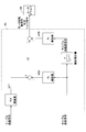
- FIG. 1 which shows the flow of control when a surface grinder moves an X-axis table.
- FIG. (1) which shows the structural example of a main controller.
- FIG. 3 is a diagram (part 2) illustrating a configuration example of a main controller;
- FIG. 6 is a diagram (part 3) illustrating a configuration example of a main controller;
- FIG. 3 is a diagram (part 2) illustrating a configuration example of a main controller;
- FIG. 6 is a diagram (part 3) illustrating a configuration example of a main controller;
- FIG. 6 is a diagram (part 4) illustrating a configuration example of a main controller; It is a figure which shows the time transition of the table position of the X-axis table, table speed, and table acceleration.
- FIG. 3 is a diagram (part 1) illustrating a configuration example of a thrust compensator;
- FIG. 6 is a diagram (part 2) illustrating a configuration example of a thrust compensator;
- FIG. (2) which shows the flow of control when a surface grinder moves an X-axis table.
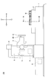
- FIG. 1 is a side view of a surface grinding machine 100 according to an embodiment of the present invention
- FIG. 2 is a top view thereof.
- the surface grinding machine 100 mainly includes a main body bed 1, an X-axis table 2, a horizontal axis grinding wheel column 3, a horizontal axis grinding wheel head 4, a grinding wheel head rotating motor 5, a grinding wheel head vertical feed motor 6, and a grinding wheel head left and right feeding.
- the main body bed 1 is a pedestal that supports an X-axis table 2 as a movable table so as to be reciprocally movable in the X-axis direction.
- the main body bed 1 has rail grooves 1AL and 1AR for receiving guide rails protruding from the lower surface of the X-axis table 2 on its upper surface.
- the X-axis table 2 is a movable table that can slide on the main body bed 1 in the X-axis direction, and supports the workpiece (workpiece) W on its upper surface.
- the horizontal axis grinding wheel column 3 is a device that supports the horizontal axis grinding wheel head 4 so as to be movable in the vertical direction (Z-axis direction) and the horizontal direction (Y-axis direction).
- the horizontal axis grinding wheel head 4 is a grinding wheel head having a grinding wheel shaft 40.
- a grinding wheel 41 is attached to the tip of the grinding wheel shaft 40.
- the grinding wheel head rotating motor 5 is a motor that rotates the grinding wheel shaft 40 of the horizontal grinding wheel head 4, and for example, a servo motor is used.
- the grinding wheel head vertical feed motor 6 is a motor that drives a grinding wheel head vertical movement mechanism for moving the horizontal grinding wheel head 4 in the vertical direction (Z-axis direction).
- the grinding wheel head vertical feed motor 6 is a servo motor for rotating a ball screw shaft or a ball screw nut in a ball screw mechanism that moves the horizontal grinding wheel head 4 in the Z-axis direction.
- the grinding wheel head left / right feeding motor 7 is a motor that drives a grinding wheel head left / right movement mechanism for moving the horizontal axis grinding wheel head 4 in the left / right direction (Y-axis direction).
- the grinding wheel head left / right feeding motor 7 is a servo motor for rotating a ball screw shaft or a ball screw nut in a ball screw mechanism that moves the horizontal grinding wheel head 4 in the Y-axis direction.
- the vertical movement mechanism and the horizontal movement mechanism may be other mechanisms such as a rack and pinion mechanism.
- the table driving motor 8 is a motor that drives a table moving mechanism for moving the X-axis table 2 in the X-axis direction.
- the table driving motor 8 is a servo motor for rotating a bidirectional hydraulic pump constituting a table moving mechanism that is a closed circuit hydraulic system.
- the control device 9 is a device that controls the movement of the surface grinding machine 100, and is, for example, a computer including a CPU, a RAM, a ROM, and the like.
- control device 9 controls the table driving motor 8 to move the workpiece W on the X-axis table 2 to a predetermined position. Further, the control device 9 controls the grinding wheel head vertical feed motor 6 and the grinding wheel head lateral feed motor 7 to move the horizontal axis grinding wheel head 4 to a predetermined position.
- control device 9 controls the grindstone head rotating motor 5 to start the rotation of the horizontal axis grindstone head 4, and controls the table driving motor 8 to move the X-axis table 2 in the + X direction.
- the grinding wheel 41 is brought into contact with the workpiece W to start the first grinding process.
- the control device 9 moves the X-axis table 2 to -X. Move it back to the original position. At that time, the control device 9 may raise the horizontal axis grinding wheel head 4 by the grinding wheel head vertical feed motor 6. This is to prevent the horizontal axis grinding wheel head 4 from coming into contact with the workpiece W when the X-axis table 2 is returned to its original position. At this time, the control device 9 may temporarily stop the grindstone head rotating motor 5.
- control device 9 rotates the horizontal axis grinding wheel head 4 by the grinding wheel head rotating motor 5 and lowers the horizontal axis grinding wheel head 4 by the grinding wheel head vertical feed motor 6. Then, the control device 9 controls the table driving motor 8 to move the X-axis table 2 in the + X direction, brings the grinding wheel 41 into contact with the workpiece W, and starts the second grinding process.
- the controller 9 performs grinding of the workpiece W by repeating the above-described movement.
- the control device 9 may perform grinding by bringing the grinding wheel 41 into contact with the workpiece W when moving the X-axis table in the ⁇ X direction.
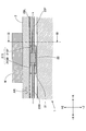
- FIGS. 3 is a front sectional view of the vertical plane including the alternate long and short dash line in each of FIGS. 1 and 2 as viewed from the direction indicated by arrow III
- FIG. 4 is the alternate long and two short dashes line in each of FIGS. It is the sectional side view which looked at the vertical plane containing No. from the direction shown by arrow IV.
- FIG. 5 is a schematic diagram illustrating a configuration example of the table moving mechanism 20.
- illustration of the main body bed 1 is abbreviate
- the table moving mechanism 20 is a mechanism that reciprocates the X-axis table 2 in the X-axis direction, and mainly includes a cylinder 21, a piston 22, a first shaft 23F, a second shaft 23B, and both. It is composed of a closed circuit hydraulic system including a directional hydraulic pump 24.
- the cylinder 21 is fixed to the lower surface of the X-axis table 2 and moves on the main body bed 1 along the X-axis table 2 in the X-axis direction.
- the cylinder 21 includes a pressure chamber 21S (see FIG. 4) inside, and receives the piston 22 in the pressure chamber 21S so that the piston 22 can slide relative to the inner wall of the pressure chamber 21S.
- the pressure chamber 21 ⁇ / b> S is separated into a first pressure chamber 21 ⁇ / b> SF and a second pressure chamber 21 ⁇ / b> SB by the piston 22.
- the first shaft 23F is a cylindrical member having one end fixed to the surface on the + X side of the piston 22 and the other end fixed to an external stationary object 23Fa.
- the second shaft 23B is a cylindrical member having one end fixed to the ⁇ X side surface of the piston 22 and the other end fixed to the external stationary object 23Ba.
- the stationary objects 23Fa and 23Ba may be any object that can hold the cylinder 21, the first shaft 23F, and the second shaft 23B stationary when the X-axis table 2 is moved. May be.
- the piston 22 is a disk member accommodated in the pressure chamber 21S so that it can move relative to the inner wall of the pressure chamber 21S within the pressure chamber 21S of the cylinder 21. Further, the surface of the piston 22 on the + X side is connected to the first shaft 23F, and the surface on the ⁇ X side is connected to the first shaft 23F.
- the cylinder 21 can reciprocate with respect to the main body bed 1 together with the X-axis table 2, whereas the first shaft 23F, the second shaft 23B, and the piston 22 are attached to the main body bed 1. It arrange
- the X-axis table 2 includes two V-shaped guide rails 2BL and 2BR protruding from the lower surface in the ⁇ Z direction. Further, the X-axis table 2 is supported by the main body bed 1 so as to reciprocate in the X-axis direction on the main body bed 1 using a hydrostatic bearing mechanism, a dynamic pressure bearing mechanism, or a combination thereof or other bearing mechanisms. Is done. Note that the shape of the guide rail is not necessarily V-shaped.
- the reciprocation of the X-axis table 2 in the X-axis direction is controlled by a bidirectional hydraulic pump 24 driven by the table driving motor 8.
- a bidirectional hydraulic pump 24 driven by the table driving motor 8.
- the hydraulic oil discharged from the second port 24B of the bidirectional hydraulic pump 24 is shown.
- the hydraulic oil in the first pressure chamber 21SF of the cylinder 21 reaches the first port 24F of the bidirectional hydraulic pump 24 through the first shaft 23F.
- the volume of the second pressure chamber 21SB increases, the volume of the first pressure chamber 21SF decreases, and the X-axis table 2 is moved in the ⁇ X direction.
- the bidirectional hydraulic pump 24 is rotationally driven by the table driving motor 8, and the hydraulic fluid having a flow rate corresponding to the rotational direction and the rotational speed of the table driving motor 8 is supplied to the first port 24 ⁇ / b> F or the second. Discharge from port 24B.
- the table driving motor 8 is driven according to the current supplied by the motor driver 8A.
- the motor driver 8A receives the motor rotation command or torque command from the main controller 9A of the controller 9 and the table drive motor 8 according to the motor rotation command or torque command from the thrust compensator 9B as a sub controller.
- the motor driver 8A may supply a current to the table driving motor 8 in accordance with a motor rotation speed command from the main controller 9A and a motor rotation speed command from the thrust compensator 9B.
- a current may be supplied to the table driving motor 8 in accordance with the torque command from and the torque command from the thrust compensator 9B.
- the motor driver 8A may supply current to the table driving motor 8 in accordance with the motor rotation speed command from the main controller 9A and the torque command from the thrust compensator 9B.
- a current may be supplied to the table driving motor 8 in accordance with the torque command and the motor rotational speed command from the thrust compensator 9B.
- the main controller 9A outputs a motor rotation speed command or a torque command to the motor driver 8A so that the cylinder 21 obtains a force for moving the X-axis table 2.
- the main controller 9A for example, sends a motor rotation speed command to the motor driver 8A so that the cylinder 21 obtains a force in the desired movement direction having the same magnitude as the inertial force of the X-axis table 2.
- a torque command is output.
- the force in the desired movement direction having the same magnitude as the inertial force of the X-axis table 2 is obtained by multiplying the mass of the X-axis table 2 (including the workpiece W) by the acceleration of the X-axis table 2. It is power.
- the main controller 9A controls the rotational speed of the bidirectional hydraulic pump 24.
- the main controller 9A generates a motor rotation speed command or a torque command based on various command values from the control device 9 and various sensor outputs from various sensors.
- the various command values are command values generated by the control device 9 in response to an operator's input or the like, and include a table position command, a table speed command, a table acceleration command, a table drive motor rotational speed command (motor Speed command).
- the various sensor outputs include outputs from the displacement sensor 30, the first cylinder pressure sensor 31F, the second cylinder pressure sensor 31B, the rotation speed sensor 32, and the like.
- the displacement sensor 30 is a displacement sensor that detects the displacement of the X-axis table 2.
- the displacement sensor 30 detects a linear displacement with respect to a predetermined reference position of the X-axis table 2, and outputs the detection result to the control device 9.
- a linear scale is used as the displacement sensor 30.
- the first cylinder pressure sensor 31F is a sensor that detects the pressure of the first pressure chamber 21SF in the cylinder 21, for example, in a pipe line that connects the first shaft 23F and the first port 24F of the bidirectional hydraulic pump 24. The pressure of the hydraulic oil is detected, and the detection result is output to the control device 9.
- the second cylinder pressure sensor 31B is a sensor that detects the pressure of the second pressure chamber 21SB in the cylinder 21, and is, for example, a pipe that connects the second shaft 23B and the second port 24B of the bidirectional hydraulic pump 24. The pressure of hydraulic oil in the road is detected, and the detection result is output to the control device 9.
- the first cylinder pressure sensor 31F and the second cylinder pressure sensor 31B may be attached to the first pressure chamber 21SF and the second pressure chamber 21SB, or may be attached to the first shaft 23F and the second shaft 23B. .
- the rotation speed sensor 32 is a sensor that detects the rotation of the table driving motor 8.
- the rotation speed sensor 32 detects the rotation direction and the rotation angle of the table driving motor 8, and outputs the detection result to the control device 9.
- a resolver is used as the rotation angle sensor 32.
- the thrust compensator 9B is a functional element that compensates for a force that is offset by a force that hinders the movement of the X-axis table 2 among the thrusts for moving the X-axis table 2.
- the thrust compensator 9 ⁇ / b> B is a force (hereinafter referred to as “preload force”) for canceling a movement drag, which is a force excluding the inertial force of the X-axis table 2, among the forces that hinder the movement of the X-axis table 2.
- the motor rotation number command or the torque command is output to the motor driver 8A so that the cylinder 21 obtains.
- the thrust compensator 9B applies to the motor driver 8A so that the cylinder 21 obtains a preload force that has the maximum static frictional force of the X-axis table 2 and faces the desired moving direction.
- Output a motor rotation speed command or torque command.
- the moving drag includes, for example, a grinding reaction force by the surface grinder 100 in addition to the frictional force.
- the thrust compensator 9B generates a motor rotation speed command or a torque command based on various command values from the control device 9 and various sensor outputs from various sensors.
- the various command values are command values generated by the control device 9 in response to an operator input or the like, and include at least the value of the compensation command.
- the various sensor outputs include outputs of the displacement sensor 30, the first cylinder pressure sensor 31F, the second cylinder pressure sensor 31B, the rotation speed sensor 32, a torque detector (not shown), and the like.
- the value of the compensation command is a value determined by the control device 9 as a compensation value determining unit, for example, a value representing a preload force.
- the control device 9 determines the value of the compensation command based on the output of the sensor. Further, the control device 9 may prepare a reference table or a function for associating the position and speed of the X-axis table 2, the differential pressure between the pressure chambers of the cylinder 21, and the value of the compensation command for the frictional force in advance. Good. In this case, the control device 9 determines the value of the compensation command using a reference table or a function from the table speed command or the table position or table speed acquired based on various sensor outputs. As a result, the control device 9 can generate the preload force at an earlier stage and can smoothly start the movement of the X-axis table 2.
- control device 9 when the control device 9 includes a sensor for measuring a grinding reaction force that is a movement drag, the control device 9 may determine the value of the compensation command based on the output of the sensor. Further, the control device 9 may prepare in advance a reference table or a function for associating the grinding conditions such as the grinding depth and the rotational speed of the grindstone shaft 40 with the value of the compensation command for the grinding reaction force. In this case, the control device 9 determines the value of the compensation command from the current grinding condition using a reference table or a function. As a result, the control device 9 can generate the preload force at an earlier stage and can smoothly start the movement of the X-axis table 2.
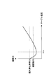
- FIG. 6 is a diagram showing the relationship between the value of the compensation command and the frictional force.
- the movement speed (table speed) of the X-axis table 2 is arranged on the horizontal axis, and the frictional force is arranged on the vertical axis.
- the frictional force of the X-axis table 2 is at the maximum static frictional force when the table speed is 0, and decreases as the table speed increases when the table speed is equal to or lower than the predetermined speed VTH .
- the table speed exceeds the predetermined speed VTH , the table speed increases as the table speed increases.
- the control device 9 changes the value of the compensation command according to the increase in the table speed, for example, along the transition of the frictional force. Further, the control device 9 may adopt a constant value equal to or less than the maximum static friction force (for example, 90% of the maximum static friction force) as the value of the compensation command regardless of the change in the table speed.
- the maximum static friction force for example, 90% of the maximum static friction force
- control device 9 may set the value of the compensation command to zero when the table speed exceeds the predetermined speed VTH . This is because the additional control by the thrust compensator 9B is executed only when the table speed is relatively low and the control by the main controller 9A is relatively unstable. Another reason is to simplify the control contents when the table speed is relatively high and the control by the main controller 9A is stable.
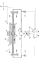
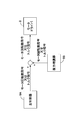
- FIG. 7 is a diagram showing a flow of control when the surface grinding machine 100 moves the X-axis table 2.
- the main controller 9 ⁇ / b> A acquires various command values including at least one of a table position command, a table speed command, a table acceleration command, and a motor speed command from the control device 9.
- the thrust compensator 9B obtains various command values including at least a compensation command from the control device 9.
- the various sensor outputs acquired by the main controller 9A are at least one of a table position signal output from the displacement sensor 30, a cylinder pressure signal output from the cylinder pressure sensors 31F and 31B, and a motor rotation angle signal output from the rotation angle sensor 32. including.
- the main controller 9A acquires a table position signal output from the displacement sensor 30.
- the main controller 9A acquires a motor rotation angle signal output from the rotation speed sensor 32.
- the thrust compensator 9B for example, when performing feedback control of the preload force, the first cylinder pressure signal output by the first cylinder pressure sensor 31F and the second cylinder pressure sensor 31B output. Get the cylinder pressure signal.
- the thrust compensator 9B monitors the thrust currently generated by the table moving mechanism 20 based on the differential pressure between the pressure chambers of the cylinder 21, and outputs the motor rotation speed command or the motor speed command output to the motor driver 8A. Determine the torque command value.
- the thrust compensator 9B may not acquire the sensor output.
- the main controller 9A and the thrust compensator 9B generate a motor rotation speed command or torque command based on the acquired various command values and various sensor outputs, respectively, and the generated motor rotation speed command or torque command is output to the motor driver. Output to 8A.
- the motor driver 8A supplies a current to the table driving motor 8 in accordance with a motor rotation speed command or a torque command from the main controller 9A and the thrust compensator 9B.
- s represents a Laplace operator
- a cyl represents the pressure receiving area of the piston 22
- V cyl represents the volume of the pressure chamber 21S
- M represents the mass of the X-axis table 2
- B represents the X-axis table 2
- K oil The viscous friction coefficient of the hydraulic oil is represented by K oil and the bulk elastic modulus of the hydraulic oil is represented.
- Flow rate Q is proportional to the motor rotation speed omega m of the table drive motor 8, if put the displacement volume per unit rotation speed and W P, the transfer function from the motor rotation speed omega m up table velocity v is less (2)
- ⁇ n and ⁇ n are the natural frequency and damping coefficient of the X-axis table 2, respectively, and are expressed by the following equations (3) and (4).
- K HST is a gain obtained by the closed circuit hydraulic system and is expressed by the following equation (5).
- the damping coefficient ⁇ n is a coefficient representing the damping property of the vibration of the X-axis table 2, and in the case of ⁇ n ⁇ 1, it represents that the vibration is damped in a shorter time as the value is closer to 1. .
- the transfer function from the speed command v dir to the table speed v is expressed by the following expression (6) based on the above expression (2).
- ⁇ c and ⁇ c are a control natural frequency and a control damping coefficient of the X-axis table 2 when the speed and acceleration of the X-axis table 2 are fed back, respectively, and the following equations (7), It is represented by (8).
- K v and K a are a speed feedback gain and an acceleration feedback gain, respectively, and are expressed by the following equations (9) and (10).
- the acceleration feedback gain K a can determine the acceleration feedback gain K a according to the value of the desired control damping coefficients zeta c, i.e., can be realized the value of the desired control damping coefficients zeta c by adjusting the acceleration feedback gain K a Means.
- the main controller 9A acquires a table position command, a table speed command, and a table position signal, and outputs a motor rotation speed command or a torque command to the motor driver 8A.
- the main controller 9A first subtracts a value PL represented by a table position signal from the displacement sensor 30 from a value represented by a table position command from the control device 9 according to a proportional control law, and obtains a predetermined gain. multiplied by K p deriving a first control value V1 with.
- the main controller 9A may use a proportional-integral control law instead of the proportional control law.
- the main controller 9A adds a value obtained by subtracting the value PL from the value represented by the table position command and a value obtained by dividing the integral value of the subtracted value by a predetermined time constant, and then adds a predetermined value.
- the first control value V1 may be derived by multiplying the gain Kp.
- the main controller 9A adds a speed feedforward value VFF obtained by multiplying the value represented by the table speed command from the control device 9 by the speed feedforward gain Kvff and the first control value V1. Then, the main controller 9A from the value after addition (V1 + VFF), by subtracting the speed feedback value VFB obtained by multiplying the velocity feedback gain K v table position signal to a value represented by the table speed signal obtained by the pseudo-differential
- V1 + VFF the speed feedforward value obtained by multiplying the value represented by the table speed command from the control device 9 by the speed feedforward gain Kvff and the first control value V1. Then, the main controller 9A from the value after addition (V1 + VFF), by subtracting the speed feedback value VFB obtained by multiplying the velocity feedback gain K v table position signal to a value represented by the table speed signal obtained by the pseudo-differential
- the second control value V2 is derived.
- the main controller 9A obtains an acceleration feedback gain from the second control value V2 to a value represented by a table acceleration signal obtained by pseudo-differentiating the table speed signal, that is, obtained by second-order pseudo-differentiating the table position signal. by subtracting the acceleration feedback value AFB multiplied by K a, derive motor rotational speed command or torque command.
- the main controller 9A adds an acceleration feedforward value AFF (not shown) obtained by multiplying the value represented by the table acceleration command from the control device 9 by the acceleration feedforward gain Kaff and the second control value V2. Then, the motor feedback command or torque command may be derived by subtracting the acceleration feedback value AFB.
- the main controller 9A may omit the calculation of the speed feedback value VFB and the subtraction of the speed feedback value VFB from the total value of the first control value V1 and the speed feedforward value VFF.
- the main controller 9A shown in FIG. 8 adjusts the acceleration feedback gain K a under the control model having the transfer function expressed by the equation (6), thereby obtaining a desired control damping coefficient ⁇ c. Can be realized.
- the surface grinding machine 100 including the main controller 9A shown in FIG. 8 can quickly attenuate the vibration of the X-axis table 2 that occurs when the X-axis table 2 is accelerated or decelerated.
- the main controller 9A acquires the first cylinder pressure signal and the second cylinder pressure signal from the first cylinder pressure sensor 31F and the second cylinder pressure sensor 31B instead of the table position signal. This is different from the case of FIG. That is, it differs from the control of FIG. 8 in which the table acceleration signal obtained by second-order differentiation of the table position signal is fed back in that the table acceleration signal derived from the pressure difference between the pressure chambers is fed back.
- the main controller 9A differs from the control of FIG. 8 in that the motor rotational speed command or the torque command is derived based on the speed feedforward value VFF without deriving the first control value V1 based on the table position command. .
- the main controller 9A first subtracts the acceleration feedback value AFB from the speed feedforward value VFF obtained by multiplying the value represented by the table speed command from the control device 9 by the speed feedforward gain Kvff , Deriving motor rotation speed command or torque command.
- the main controller 9A derives the acceleration feedback value AFB based on the first cylinder pressure signal and the second cylinder pressure signal.
- the main controller 9A derives the difference between the first cylinder pressure signal and the second cylinder pressure signal, and applies a low-pass filter and a high-pass filter to the derived value.
- the low-pass filter is a functional element for removing noise included in the difference
- the high-pass filter is a functional element for removing the influence of the frictional force included in the difference.
- the signal after applying the low-pass filter and the high-pass filter has, for example, a frequency of about 1/3 to 5 times the natural frequency of the X-axis table 2.
- the main controller 9A multiplies the differential pressure signal by A cyl / M to obtain a table acceleration signal. That is, the main controller 9A multiplies the value represented by the differential pressure signal by the pressure receiving area A cyl of the piston 22 based on the equation of motion to derive the driving force by the bidirectional hydraulic pump 24, and calculates the driving force by the X-axis table. Divide by the mass M of 2 to derive the acceleration of the X-axis table 2. It should be noted that the mass M used when the velocity feedback gain is determined by the equation (9), the acceleration feedback gain is determined by the equation (10), and the acceleration of the X-axis table 2 is derived from the differential pressure signal, May vary depending on mass. In this case, instead of the actual mass, the nominal mass may be used as the value of the mass M. It is desirable to use the maximum mass of the workpiece W that can be mounted on the X-axis table 2 as the nominal mass.
- the main controller 9A derives acceleration feedback value AFB by multiplying the acceleration feedback gain K a to the value table acceleration signal represents.
- the main controller 9 ⁇ / b> A has an acceleration feedforward value AFF (not shown) obtained by multiplying the value represented by the table acceleration command from the control device 9 by the acceleration feedforward gain K aff .
- the motor feedback command AFB may be derived by subtracting the acceleration feedback value AFB.
- the main controller 9A shown in FIG. 9 does not acquire the cylinder pressure signal from each of the first cylinder pressure sensor 31F and the second cylinder pressure sensor 31B, but instead of the first pressure chamber 21SF and the second pressure chamber 21SB.
- a differential pressure signal may be acquired from a differential pressure sensor (not shown) that detects a differential pressure therebetween.
- the main controller 9A shown in Figure 9 similarly to the case shown in FIG. 8, under the control model having a transfer function represented by the formula (6), by adjusting the acceleration feedback gain K a
- the desired control damping coefficient ⁇ c can be realized.
- the surface grinding machine 100 including the main controller 9A shown in FIG. 9 can quickly attenuate the vibration of the X-axis table 2 that occurs when the X-axis table 2 is accelerated or decelerated.
- the main controller 9A is different from the case of FIG. 8 in that it obtains a table speed signal from a table speed sensor (not shown) such as a tachometer instead of the table position signal. . That is, it differs from the control of FIG. 8 in which the table acceleration signal obtained by second-order differentiation of the table position signal is fed back in that the table acceleration signal obtained by first-order differentiation of the table speed signal is fed back.
- a table speed sensor such as a tachometer
- the main controller 9A differs from the control of FIG. 8 in that the motor rotational speed command or the torque command is derived based on the speed feedforward value VFF without deriving the first control value V1 based on the table position command. .
- the main controller 9A first derives a speed feedforward value VFF obtained by multiplying the value represented by the table speed command from the control device 9 by the speed feedforward gain Kvff .
- the main controller 9A from the speed feedforward value VFF, by subtracting the speed feedback value VFB obtained by multiplying the velocity feedback gain K v to the value table speed signal represents, derive a second control value V2.
- the main controller 9A from the second control value V2, by subtracting the acceleration feedback value AFB obtained by multiplying the acceleration feedback gain K a to the value represented by the table acceleration signal obtained by first-order quasi-differentiation of the table speed signal
- the motor rotational speed command or torque command is derived.
- the main controller 9A also uses the value AFF (not shown) obtained by multiplying the value represented by the table acceleration command from the control device 9 by the acceleration feedforward gain K aff , and the second control.
- the motor rotation speed command or torque command may be derived by adding the value V2 and subtracting the acceleration feedback value AFB.
- the main controller 9A may omit calculation of the speed feedback value VFB and subtraction of the speed feedback value VFB from the speed feedforward value VFF.
- the main controller 9A shown in FIG. 10 similarly to the case shown in FIG. 8, under the control model having a transfer function represented by the formula (6), by adjusting the acceleration feedback gain K a
- the desired control damping coefficient ⁇ c can be realized.
- the surface grinding machine 100 including the main controller 9A shown in FIG. 10 can quickly attenuate the vibration of the X-axis table 2 that occurs when the X-axis table 2 is accelerated or decelerated.
- the main controller 9A acquires a table acceleration signal from a table acceleration sensor (not shown) instead of the table position signal. That is, it differs from the control of FIG. 8 in which the table acceleration signal obtained by second-order differentiation of the table position signal is fed back in that the table acceleration signal obtained directly from the table acceleration sensor is fed back.
- the main controller 9A differs from the control of FIG. 8 in that the motor rotational speed command or the torque command is derived based on the speed feedforward value VFF without deriving the first control value V1 based on the table position command. .
- the main controller 9A first derives a speed feedforward value VFF obtained by multiplying the value represented by the table speed command from the control device 9 by the speed feedforward gain Kvff .
- the main controller 9A subtracts the acceleration feedback value AFB from the speed feedforward value VFF to derive a motor rotation speed command or a torque command.
- the main controller 9 ⁇ / b> A has an acceleration feedforward value AFF (not shown) obtained by multiplying the value represented by the table acceleration command from the control device 9 by the acceleration feedforward gain Kaff .
- the motor feedback command AFB may be derived by subtracting the acceleration feedback value AFB.
- the main controller 9A shown in FIG. 11 similarly to the case shown in FIG. 8, under the control model having a transfer function represented by the formula (6), by adjusting the acceleration feedback gain K a
- the desired control damping coefficient ⁇ c can be realized.
- the surface grinding machine 100 including the main controller 9A of FIG. 11 can attenuate the vibration of the X-axis table 2 that occurs when the X-axis table 2 is accelerated or decelerated at an early stage.
- the main controller 9A may omit obtaining either the table position command or the table speed command.
- the main controller 9A may omit feedback control based on part or all of the table position, table speed, and table acceleration, and feed based on part or all of the table position, table speed, and table acceleration.
- the forward control may be omitted.
- the main controller 9A shown in FIGS. 9 to 11 cancels the difference between the actual table position value and the value represented by the table position command, or represents the actual table speed value and the table speed command.
- the motor rotational speed command or torque command may be derived so as to cancel the difference from the value.
- the main controller 9A shown in FIGS. 9 to 11 speeds the first control signal V1 calculated based on the value represented by the table position command and the value PL represented by the table position signal, as in FIG. You may make it add to feedforward value VFF.
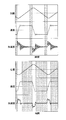
- FIG. 12 is a diagram showing temporal transitions of the table position, table speed, and table acceleration of the X-axis table 2.
- the upper diagram of FIG. 12 shows the transition when the acceleration feedback value AFB is not used, and the lower diagram of FIG. Shows the transition when the acceleration feedback value AFB is used. Further, the time transition of the table position is common in the upper diagram of FIG. 12 and the lower diagram of FIG.
- the hatched area in FIG. 12 represents the time from when the table acceleration value becomes less than the predetermined value and the table speed is settled until the table acceleration value becomes equal to or greater than the predetermined value and the table speed fluctuates.
- the table acceleration value becomes less than the predetermined value after the table acceleration value becomes equal to or greater than the predetermined value and the table speed becomes less than the predetermined value until the table speed is stabilized.
- the hatched area is referred to as a table speed stable period
- the non-hatched area (white area) is referred to as a table speed fluctuation period.
- the table speed fluctuation period when the acceleration feedback value AFB is used (white area in the lower diagram of FIG. 12) is the table speed fluctuation period when the acceleration feedback value AFB is not used (white area of the upper diagram of FIG. 12). Shorter than (region). Further, the table speed stable period when the acceleration feedback value AFB is used (hatched area in the lower diagram of FIG. 12) is compared with the table speed stable period when the acceleration feedback value AFB is not used (hatched area in the upper diagram of FIG. 12). long. This means that the portion that can be used for grinding the workpiece W in one stroke of the X-axis table 2 becomes longer. Moreover, it means that the allowable maximum length in the X-axis direction of the workpiece W placed on the X-axis table 2 can be further increased. That is, all of grinding efficiency, energy efficiency, and applicability are improved.
- the surface grinding machine 100 provided with the main controller 9A attenuates the vibration of the X-axis table 2 caused by the acceleration / deceleration of the X-axis table 2 at an early stage, and the grinding efficiency, energy efficiency, and application Can be improved.
- the operator of the surface grinder 100 with a master controller. 9A by appropriately adjusting the acceleration feedback gain K a, it is possible to shorten the settling time of the table velocity in the X-axis table 2.
- the operator by adjusting the acceleration feedback gain K a to approach the value of the control damping coefficients zeta c to 1, reduced or that the table velocity in the X-axis table 2 overshoot the value of the speed command Can be prevented.
- the thrust compensator 9B acquires a compensation command from the control device 9, and outputs a motor rotation speed command or a torque command to the motor driver 8A.
- the thrust compensator 9B is a value F 0 representative of the compensation command from the control unit 9, to obtain the value of the torque command by multiplying the W P / A cyl.
- W P is a displacement volume per unit rotation of the bidirectional hydraulic pump 24
- a cyl is the pressure receiving area of the piston 22. Therefore, F 0 / A cyl represents the differential pressure DP 0 between the pressure chamber of the cylinder 21, DP 0 ⁇ W P represents the torque due to the bidirectional hydraulic pump 24.
- the thrust compensator 9B is over the designated pressure difference DP 0 necessary for generating the preloading force, derive the value of the torque required to generate the differential pressure DP 0, derived was The value is output as a torque command value to the motor driver 8A.
- the thrust compensator 9B acquires a table acceleration command from the control device 9, and the first cylinder pressure signal and the second cylinder pressure from the first cylinder pressure sensor 31F and the second cylinder pressure sensor 31B. It differs from the case of FIG. 13 in that a signal is acquired.
- the thrust compensator 9B derives the inertial force of the X-axis table 2 by multiplying the value of the table acceleration command by the mass M of the X-axis table 2.
- the thrust compensator 9B multiplies the difference between the first cylinder pressure signal and the second cylinder pressure signal by the pressure receiving area A cyl of the piston 22 to derive the thrust by the bidirectional hydraulic pump 24.
- the thrust compensator 9B adds the preload force indicated by the value of the compensation command and the inertial force of the X-axis table 2.
- the preload force is added as having the same sign as the inertial force of the X-axis table 2 when the X-axis table 2 is accelerated. That is, the preload force is positive when the inertial force is positive, and the preload force is negative when the inertial force is negative.
- the preload force is added as having an opposite sign to the inertial force of the X-axis table 2.
- the preload force is a positive value when the inertial force is a negative value
- the preload force is a negative value when the inertial force is a positive value.
- the value calculated in this way means a force that hinders the movement of the X-axis table 2.
- the preload force is a reverse force having the same magnitude as the movement drag, which is a force obtained by removing the inertial force of the X-axis table 2 from the force that hinders the movement of the X-axis table 2.
- the thrust compensator 9B can eliminate the influence of the movement drag
- the main controller 9A controls the bidirectional hydraulic pump 24 so that the X-axis table 2 accelerates and decelerates according to various command values. can do.
- the thrust compensator 9B subtracts the thrust by the bidirectional hydraulic pump 24 from the force that hinders the movement of the X-axis table 2 calculated as described above, and derives the control value V3.
- the thrust compensator 9B multiplies the control value V3 by a predetermined compensation gain K comp to derive a motor rotation speed command or torque command for compensating for the thrust canceled by the movement drag.
- the thrust compensator 9B determines the direction in which the X-axis table 2 is to be moved next.
- the control value V3 is derived by subtracting the thrust from the bidirectional hydraulic pump 24 from the preload force in the positive direction of the preload force. If the direction in which the X-axis table 2 is to be moved next is not yet determined, the direction in which the X-axis table 2 was moved last time may be the positive direction of the preload force.
- the X-axis table 2 When grinding a surface perpendicular to the X-axis, the X-axis table 2 is set to a predetermined value in order to repeat the grinding process at a predetermined grinding depth for a plurality of times in order to achieve a desired grinding depth. This is because it may be moved intermittently in one direction depending on the grinding depth.
- the thrust compensator 9B multiplies the control value V3 by a predetermined compensation gain K comp to derive a motor rotational speed command or torque command for compensating for the thrust canceled by the movement drag. That is, the thrust by the bidirectional hydraulic pump 24 is made to be a preload force.
- the thrust compensator 9B determines the value of the motor rotation speed command or the torque command so that the differential pressure between the pressure chambers of the cylinder 21 becomes a differential pressure necessary to generate a desired preload force.
- the determined value is output to the motor driver 8A. That is, the thrust compensator 9B outputs the value of the motor rotation speed command or the torque command determined based on the feedback control of the differential pressure between the pressure chambers of the cylinder 21 to the motor driver 8A.
- the thrust compensator 9B may obtain the table acceleration signal by second-order differentiation of the table position signal output from the displacement sensor 30, instead of obtaining the table acceleration command from the control device 9.
- a table acceleration signal may be obtained by first-order differentiation of a table speed signal output from a table speed sensor (not shown) such as an tacho generator.
- the table acceleration signal may be obtained from an acceleration sensor (not shown). You may obtain it directly.
- the thrust compensator 9B may use a PI controller instead of a multiplier that multiplies the compensation gain K comp .
- the motor driver 8A receives the motor rotation speed command or the torque command output separately from the main controller 9A and the thrust compensator 9B, respectively.
- the present invention is not limited to this.
- the motor driver 8A receives the total value of the motor rotational speed command value output from the main controller 9A and the motor rotational speed command value output from the thrust compensator 9B. Also good.
- the motor driver 8A may receive the total value of the torque command value output from the main controller 9A and the torque command value output from the thrust compensator 9B.
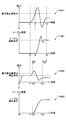
- FIG. 16 is a diagram showing a time transition of the thrust by the bidirectional hydraulic pump 24 and a time transition of the table speed of the X-axis table 2.
- F16A1 indicates a time transition of thrust when the thrust compensator 9B is not used
- F16B1 indicates a time transition of table speed when the thrust compensator 9B is not used
- F16A2 indicates the time transition of the thrust when the thrust compensator 9B is used
- F16B2 indicates the time transition of the table speed when the thrust compensator 9B is used.
- the thrust by the bidirectional hydraulic pump 24 starts to rise at time t1, as indicated by F16A1. This is because, for example, the operator inputs a movement command for the X-axis table 2 to the control device 9, and the control of the table driving motor 8 by the main controller 9A is started. Note that the table speed of the X-axis table 2 remains zero. This is because the thrust is less than the maximum static friction force.
- the X-axis table 2 starts to move.
- the table speed of the X-axis table 2 increases and overshoots exceeding the value of the table speed command. This is because the time between time t1 and time t2 is relatively long, and the rate of increase in the value of the motor rotation speed command or torque command by the main controller 9A is excessively large. That is, although the main controller 9A increases the value of the motor rotation speed command or the torque command, the time during which the table speed remains zero is relatively long. This tendency becomes more prominent as the time between time t1 and time t2 is longer.
- the thrust decreases rapidly and further increases in the opposite direction. This is because the main controller 9A sharply decreases the value of the motor rotation speed command or torque command in order to cancel the overshoot. As a result, the table speed undershoots below the value of the table speed command.
- the table speed converges to the value of the table speed command at time t3 while repeating such overshoot and undershoot.
- F16B1 shows a state in which overshoot and undershoot each occur once for the sake of clarity.
- the thrust by the bidirectional hydraulic pump 24 is input to the control device 9 at time t0, that is, the movement command of the X-axis table 2 by the operator. Before the rise begins. Then, the thrust by the bidirectional hydraulic pump 24 rises to the value of the compensation command. This is because the control of the table driving motor 8 for generating the preload force by the thrust compensator 9B is started. The value of the compensation command is determined so as to be equal to or less than the maximum static friction force. This is because the X-axis table 2 moves before the movement command by the operator is input to the control device 9 when the maximum static friction force is greater. For this reason, the table speed of the X-axis table 2 remains zero, but the X-axis table 2 becomes movable by applying a slight thrust.
- the thrust compensator 9B estimates the subsequent movement direction of the X-axis table 2 based on the current position of the X-axis table 2 and various information related to grinding. As a result, the thrust compensator 9B can generate a preload force in the estimated direction before the operator inputs a movement command for the X-axis table 2 to the control device 9.
- the thrust by the bidirectional hydraulic pump 24 exceeds the maximum static frictional force at time t2a, and the X-axis table 2 starts moving.
- the table speed of the X-axis table 2 increases relatively slowly as compared with the case of F16A1, and converges to the value of the table speed command at time t3a without causing overshoot and undershoot.
- the time between time t1 and time t2a is shorter by time D1
- the rate of increase in the value of the motor rotation speed command or torque command by the main controller 9A is excessive. It is because it does not become big. That is, because the main controller 9A increases the value of the motor rotation speed command or torque command, the time during which the table speed remains zero is short.
- the time until the table speed is settled is shortened by a time D2 as compared with the case where the thrust compensator 9B is not used.
- the thrust compensator 9B compensates for the force that is canceled out by the movement drag if the absolute value of the table speed is less than the predetermined speed VTH .
- the surface grinding machine 100 including the thrust compensator 9B can start the movement of the X-axis table 2 early and smoothly. Further, it is possible to suppress or prevent the table speed overshoot and undershoot that occur immediately after the movement of the X-axis table 2 is started.
- the surface grinding machine 100 employs the horizontal axis grinding wheel head 4, but a vertical axis grinding wheel head may be employed.
- the grindstone head may include a tiltable shaft.
- the main controller 9A and the thrust compensator 9B control the table driving motor 8 that drives the bidirectional hydraulic pump constituting the table moving mechanism of the surface grinding machine 100.
- the present invention is not limited to this.
- the main controller 9A and the thrust compensator 9B control a motor that drives a bidirectional hydraulic pump that constitutes a closed circuit hydraulic system that moves heavy objects, which is mounted on a construction machine, an injection molding machine, a machine tool, or the like. You may do.
- the thrust compensator 9B compensates for a force that is offset by excavation reaction force in the construction machine, cutting reaction force in the machine tool, and the like, among the forces generated by the motor.
- the closed circuit hydraulic system uses the pressure (hydraulic pressure) of hydraulic oil.
- the closed circuit hydraulic system may use, for example, a pressure (hydraulic pressure) of a liquid having low compressibility such as water instead of the hydraulic pressure.
- the main controller 9A controls the rotational speed of the bidirectional hydraulic pump 24 via the motor driver 8A and the table driving motor 8.
- the present invention is not limited to this.
- the main controller 9A may control the rotational speed of the bidirectional hydraulic pump 24 by an internal combustion engine instead of controlling the rotational speed of the bidirectional hydraulic pump 24 by the table driving motor 8.
Landscapes
- Engineering & Computer Science (AREA)
- Mechanical Engineering (AREA)
- Physics & Mathematics (AREA)
- Fluid Mechanics (AREA)
- Constituent Portions Of Griding Lathes, Driving, Sensing And Control (AREA)
- Grinding Of Cylindrical And Plane Surfaces (AREA)
- Control Of Multiple Motors (AREA)
Abstract
L'invention porte sur une rectifieuse de surface (100) qui amène une table d'axe x (2) à se déplacer en utilisant un mécanisme de déplacement de table (20) qui comprend une pompe hydraulique bidirectionnelle (24), et la rectifieuse de surface comporte les éléments suivants : un dispositif de commande (9) destiné à commander le mouvement de la table d'axe x (2), dans lequel la position ou la vitesse de la table d'axe x (2) sert de cible de commande ; une unité de commande principale (9A) destinée à commander la pompe hydraulique bidirectionnelle (24), en fonction d'une instruction de position de table ou d'une instruction de vitesse de table issues du dispositif de commande (9) ; et un compensateur de poussée (9B) destiné à commander la pompe hydraulique bidirectionnelle (24) de façon à annuler la force qui inhibe le déplacement de la table d'axe x (2).
Priority Applications (2)
| Application Number | Priority Date | Filing Date | Title |
|---|---|---|---|
| KR1020147025316A KR101595683B1 (ko) | 2012-04-12 | 2013-01-29 | 평면 연삭반 |
| CN201380013040.3A CN104169046B (zh) | 2012-04-12 | 2013-01-29 | 平面磨床 |
Applications Claiming Priority (2)
| Application Number | Priority Date | Filing Date | Title |
|---|---|---|---|
| JP2012091326A JP5801246B2 (ja) | 2012-04-12 | 2012-04-12 | 平面研削盤 |
| JP2012-091326 | 2012-04-12 |
Publications (1)
| Publication Number | Publication Date |
|---|---|
| WO2013153836A1 true WO2013153836A1 (fr) | 2013-10-17 |
Family
ID=49327416
Family Applications (1)
| Application Number | Title | Priority Date | Filing Date |
|---|---|---|---|
| PCT/JP2013/051933 WO2013153836A1 (fr) | 2012-04-12 | 2013-01-29 | Rectifieuse de surface |
Country Status (4)
| Country | Link |
|---|---|
| JP (1) | JP5801246B2 (fr) |
| KR (1) | KR101595683B1 (fr) |
| CN (1) | CN104169046B (fr) |
| WO (1) | WO2013153836A1 (fr) |
Cited By (1)
| Publication number | Priority date | Publication date | Assignee | Title |
|---|---|---|---|---|
| CN104275646A (zh) * | 2014-10-23 | 2015-01-14 | 湖南坤鼎数控科技有限公司 | 磨削定位控制方法、控制系统及磨削定位装置 |
Families Citing this family (4)
| Publication number | Priority date | Publication date | Assignee | Title |
|---|---|---|---|---|
| CN105364680A (zh) * | 2015-12-28 | 2016-03-02 | 常熟市尚高机械设备有限公司 | 一种新型磨削装置 |
| CN106181769A (zh) * | 2016-08-30 | 2016-12-07 | 佛山市诚志齿轮有限公司 | 一种磨床工作台行程控制装置、系统及方法 |
| JP7478105B2 (ja) * | 2021-01-13 | 2024-05-02 | 住友重機械工業株式会社 | 流体アクチュエータ、流体アクチュエータの制御方法、流体アクチュエータの制御プログラム |
| CN113927376B (zh) * | 2021-10-20 | 2023-04-14 | 国网福建省电力有限公司 | 基于母排接触面打磨工具的振动的控制方法及控制装置 |
Citations (6)
| Publication number | Priority date | Publication date | Assignee | Title |
|---|---|---|---|---|
| JPS62184206A (ja) * | 1986-02-07 | 1987-08-12 | Hitachi Seiko Ltd | 電気−油圧変換式駆動装置 |
| JPS62168250U (fr) * | 1986-04-16 | 1987-10-26 | ||
| JPS6372980A (ja) * | 1986-09-12 | 1988-04-02 | Takeshi Chikamoto | 研削盤のテ−ブル駆動方法 |
| JPS63221942A (ja) * | 1987-03-10 | 1988-09-14 | Hiroshi Nakazawa | 高速送り機構 |
| JPH03117545U (fr) * | 1990-03-12 | 1991-12-04 | ||
| JP2004001133A (ja) * | 2002-05-31 | 2004-01-08 | Brother Ind Ltd | 超音波加工装置及び超音波加工方法 |
Family Cites Families (7)
| Publication number | Priority date | Publication date | Assignee | Title |
|---|---|---|---|---|
| JPH02118201A (ja) * | 1988-10-27 | 1990-05-02 | Sumitomo Heavy Ind Ltd | シリンダアクチュエータ |
| JPH05293550A (ja) * | 1992-04-16 | 1993-11-09 | Amada Co Ltd | ワーク曲げ加工機の加工方法および装置 |
| US5778671A (en) * | 1996-09-13 | 1998-07-14 | Vickers, Inc. | Electrohydraulic system and apparatus with bidirectional electric-motor/hydraulic-pump unit |
| JP2002276611A (ja) * | 2001-03-19 | 2002-09-25 | Amada Eng Center Co Ltd | 油圧作動システム、板金加工機械、及び産業機械 |
| JP2004332890A (ja) * | 2003-05-12 | 2004-11-25 | Mitsui Eng & Shipbuild Co Ltd | 上下動補償機能付巻上げ装置 |
| CN201521512U (zh) * | 2009-10-19 | 2010-07-07 | 路文忠 | 采用伺服电机直驱的数字式电液伺服驱动装置 |
| CN101961847A (zh) * | 2010-08-31 | 2011-02-02 | 大丰市远大机床有限公司 | 小型平面磨床工作台的液压传动系统 |
-
2012
- 2012-04-12 JP JP2012091326A patent/JP5801246B2/ja active Active
-
2013
- 2013-01-29 CN CN201380013040.3A patent/CN104169046B/zh active Active
- 2013-01-29 WO PCT/JP2013/051933 patent/WO2013153836A1/fr active Application Filing
- 2013-01-29 KR KR1020147025316A patent/KR101595683B1/ko active IP Right Grant
Patent Citations (6)
| Publication number | Priority date | Publication date | Assignee | Title |
|---|---|---|---|---|
| JPS62184206A (ja) * | 1986-02-07 | 1987-08-12 | Hitachi Seiko Ltd | 電気−油圧変換式駆動装置 |
| JPS62168250U (fr) * | 1986-04-16 | 1987-10-26 | ||
| JPS6372980A (ja) * | 1986-09-12 | 1988-04-02 | Takeshi Chikamoto | 研削盤のテ−ブル駆動方法 |
| JPS63221942A (ja) * | 1987-03-10 | 1988-09-14 | Hiroshi Nakazawa | 高速送り機構 |
| JPH03117545U (fr) * | 1990-03-12 | 1991-12-04 | ||
| JP2004001133A (ja) * | 2002-05-31 | 2004-01-08 | Brother Ind Ltd | 超音波加工装置及び超音波加工方法 |
Cited By (1)
| Publication number | Priority date | Publication date | Assignee | Title |
|---|---|---|---|---|
| CN104275646A (zh) * | 2014-10-23 | 2015-01-14 | 湖南坤鼎数控科技有限公司 | 磨削定位控制方法、控制系统及磨削定位装置 |
Also Published As
| Publication number | Publication date |
|---|---|
| JP5801246B2 (ja) | 2015-10-28 |
| KR20140134290A (ko) | 2014-11-21 |
| KR101595683B1 (ko) | 2016-02-18 |
| CN104169046B (zh) | 2016-08-24 |
| CN104169046A (zh) | 2014-11-26 |
| JP2013220481A (ja) | 2013-10-28 |
Similar Documents
| Publication | Publication Date | Title |
|---|---|---|
| JP5832964B2 (ja) | 平面研削盤 | |
| JP5801246B2 (ja) | 平面研削盤 | |
| JP2008522117A (ja) | 油圧駆動システム | |
| WO2012176761A1 (fr) | Dispositif d'amortissement d'autorail | |
| US10247301B2 (en) | Servo control system with position compensation function for driven member | |
| JP5457901B2 (ja) | 位置制御装置 | |
| JP4189764B2 (ja) | プレス機械のスライド駆動装置 | |
| KR102369766B1 (ko) | 위치제어장치, 유압구동장치 | |
| JP2021037523A (ja) | プレス機械 | |
| JP7308458B2 (ja) | 制振装置 | |
| JP5391978B2 (ja) | 流体保持装置 | |
| JP4988405B2 (ja) | モータ制御装置 | |
| JP5927879B2 (ja) | アクチュエータ制御装置 | |
| JP5801830B2 (ja) | 機械プレスのスライドモーション制御装置 | |
| JP7372189B2 (ja) | 油圧駆動位置制御装置 | |
| JP2023012272A (ja) | 位置制御装置 | |
| KR20210113331A (ko) | 산업 기계, 제어 장치, 제어 보정 장치, 및 제어 방법 | |
| JP2011075072A (ja) | 流体保持装置 | |
| JP2001321998A (ja) | プレス機械のスライド駆動装置 | |
| JPS5914442A (ja) | 移動体の振動防止装置 | |
| JPH0122641B2 (fr) |
Legal Events
| Date | Code | Title | Description |
|---|---|---|---|
| 121 | Ep: the epo has been informed by wipo that ep was designated in this application |
Ref document number: 13775306 Country of ref document: EP Kind code of ref document: A1 |
|
| ENP | Entry into the national phase |
Ref document number: 20147025316 Country of ref document: KR Kind code of ref document: A |
|
| NENP | Non-entry into the national phase |
Ref country code: DE |
|
| 122 | Ep: pct application non-entry in european phase |
Ref document number: 13775306 Country of ref document: EP Kind code of ref document: A1 |