WO2013146234A1 - Toner pour développer une image électrostatique - Google Patents
Toner pour développer une image électrostatique Download PDFInfo
- Publication number
- WO2013146234A1 WO2013146234A1 PCT/JP2013/056858 JP2013056858W WO2013146234A1 WO 2013146234 A1 WO2013146234 A1 WO 2013146234A1 JP 2013056858 W JP2013056858 W JP 2013056858W WO 2013146234 A1 WO2013146234 A1 WO 2013146234A1
- Authority
- WO
- WIPO (PCT)
- Prior art keywords
- toner
- wax
- dust
- developing toner
- electrostatic
- Prior art date
Links
Images


Classifications
-
- G—PHYSICS
- G03—PHOTOGRAPHY; CINEMATOGRAPHY; ANALOGOUS TECHNIQUES USING WAVES OTHER THAN OPTICAL WAVES; ELECTROGRAPHY; HOLOGRAPHY
- G03G—ELECTROGRAPHY; ELECTROPHOTOGRAPHY; MAGNETOGRAPHY
- G03G9/00—Developers
- G03G9/08—Developers with toner particles
- G03G9/093—Encapsulated toner particles
- G03G9/09307—Encapsulated toner particles specified by the shell material
- G03G9/09335—Non-macromolecular organic compounds
-
- G—PHYSICS
- G03—PHOTOGRAPHY; CINEMATOGRAPHY; ANALOGOUS TECHNIQUES USING WAVES OTHER THAN OPTICAL WAVES; ELECTROGRAPHY; HOLOGRAPHY
- G03G—ELECTROGRAPHY; ELECTROPHOTOGRAPHY; MAGNETOGRAPHY
- G03G15/00—Apparatus for electrographic processes using a charge pattern
-
- G—PHYSICS
- G03—PHOTOGRAPHY; CINEMATOGRAPHY; ANALOGOUS TECHNIQUES USING WAVES OTHER THAN OPTICAL WAVES; ELECTROGRAPHY; HOLOGRAPHY
- G03G—ELECTROGRAPHY; ELECTROPHOTOGRAPHY; MAGNETOGRAPHY
- G03G9/00—Developers
- G03G9/08—Developers with toner particles
-
- G—PHYSICS
- G03—PHOTOGRAPHY; CINEMATOGRAPHY; ANALOGOUS TECHNIQUES USING WAVES OTHER THAN OPTICAL WAVES; ELECTROGRAPHY; HOLOGRAPHY
- G03G—ELECTROGRAPHY; ELECTROPHOTOGRAPHY; MAGNETOGRAPHY
- G03G9/00—Developers
- G03G9/08—Developers with toner particles
- G03G9/0821—Developers with toner particles characterised by physical parameters
-
- G—PHYSICS
- G03—PHOTOGRAPHY; CINEMATOGRAPHY; ANALOGOUS TECHNIQUES USING WAVES OTHER THAN OPTICAL WAVES; ELECTROGRAPHY; HOLOGRAPHY
- G03G—ELECTROGRAPHY; ELECTROPHOTOGRAPHY; MAGNETOGRAPHY
- G03G9/00—Developers
- G03G9/08—Developers with toner particles
- G03G9/0825—Developers with toner particles characterised by their structure; characterised by non-homogenuous distribution of components
-
- G—PHYSICS
- G03—PHOTOGRAPHY; CINEMATOGRAPHY; ANALOGOUS TECHNIQUES USING WAVES OTHER THAN OPTICAL WAVES; ELECTROGRAPHY; HOLOGRAPHY
- G03G—ELECTROGRAPHY; ELECTROPHOTOGRAPHY; MAGNETOGRAPHY
- G03G9/00—Developers
- G03G9/08—Developers with toner particles
- G03G9/087—Binders for toner particles
- G03G9/08702—Binders for toner particles comprising macromolecular compounds obtained by reactions only involving carbon-to-carbon unsaturated bonds
- G03G9/08726—Polymers of unsaturated acids or derivatives thereof
- G03G9/08733—Polymers of unsaturated polycarboxylic acids
-
- G—PHYSICS
- G03—PHOTOGRAPHY; CINEMATOGRAPHY; ANALOGOUS TECHNIQUES USING WAVES OTHER THAN OPTICAL WAVES; ELECTROGRAPHY; HOLOGRAPHY
- G03G—ELECTROGRAPHY; ELECTROPHOTOGRAPHY; MAGNETOGRAPHY
- G03G9/00—Developers
- G03G9/08—Developers with toner particles
- G03G9/087—Binders for toner particles
- G03G9/08775—Natural macromolecular compounds or derivatives thereof
- G03G9/08782—Waxes
-
- G—PHYSICS
- G03—PHOTOGRAPHY; CINEMATOGRAPHY; ANALOGOUS TECHNIQUES USING WAVES OTHER THAN OPTICAL WAVES; ELECTROGRAPHY; HOLOGRAPHY
- G03G—ELECTROGRAPHY; ELECTROPHOTOGRAPHY; MAGNETOGRAPHY
- G03G9/00—Developers
- G03G9/08—Developers with toner particles
- G03G9/093—Encapsulated toner particles
- G03G9/09307—Encapsulated toner particles specified by the shell material
- G03G9/09314—Macromolecular compounds
-
- G—PHYSICS
- G03—PHOTOGRAPHY; CINEMATOGRAPHY; ANALOGOUS TECHNIQUES USING WAVES OTHER THAN OPTICAL WAVES; ELECTROGRAPHY; HOLOGRAPHY
- G03G—ELECTROGRAPHY; ELECTROPHOTOGRAPHY; MAGNETOGRAPHY
- G03G9/00—Developers
- G03G9/08—Developers with toner particles
- G03G9/093—Encapsulated toner particles
- G03G9/0935—Encapsulated toner particles specified by the core material
- G03G9/09357—Macromolecular compounds
Definitions
- the present invention relates to an electrostatic charge image developing toner used in an electrophotographic copying machine and an image forming apparatus.
- Patent Document 1 proposes a toner for developing an electrostatic image that can achieve both low-temperature fixability and blocking resistance while suppressing dust generated during fixing.
- the electrostatic image developing toner proposed in Patent Document 1 provides a toner having excellent low-temperature fixing and blocking resistance while suppressing dust generated during fixing, but has a high resistance to hot offset. It was not satisfactory.
- the hot offset resistance means that when the toner is melted by the heat received from the fixing device and the viscosity is lowered, the toner adheres to the fixing roller side due to insufficient release force or internal cohesion of the toner. In other words, the toner partially stretched between the fixing roller and the paper returns to the paper side, thereby generating a gloss unevenness called a blister and preventing the phenomenon of image deterioration.
- the resistance to hot offset is not practical.
- the object of the present invention is to improve the hot offset resistance at the time of graphic use in which the toner adhesion amount for electrostatic image development on the paper increases while suppressing dust generated during fixing, and for electrostatic image development with excellent image quality. To provide toner.
- the present inventors have obtained a specific numerical range in which the amount of sublimable substance released from the toner (the amount of dust emission (Dt)) is calculated by a specific formula. In this case, the present inventors have found that hot offset resistance is improved while suppressing dust generated during fixing, and the present invention has been completed.
- the present invention is as follows.
- the wax has a melting point of 55 ° C. or more and 90 ° C. or less when contained in the electrostatic image developing toner, and the electrostatic charge image developing toner has a dust emission amount (Dt) of An electrostatic image developing toner satisfying the formula (1).
- Dt represents the amount of dust emitted per minute (CPM) generated when the electrostatic image developing toner is heated
- Vp represents the printing speed (sheet / sheet in A4 horizontal conversion in the image forming apparatus). Minutes).
- the electrostatic image developing toner contains at least two types of waxes, ie, a wax component X and a wax component Y.
- the dust emission amount of the wax component Y is larger than the dust emission amount of the wax component X.
- the content of the wax component X is larger than the content of the wax component Y.
- (A) The electrostatic image developing toner contains at least two types of waxes, ie, a wax component X and a wax component Y.
- the dust emission amount of the wax component Y is larger than the dust emission amount of the wax component X.
- the dust emission amount of the wax component X is 50,000 CPM or less, and the dust emission amount of the wax component Y is 100,000 CPM or more.
- Toner for developing electrostatic images [11] The toner for developing an electrostatic charge image has a region where the abundance ratio of the wax component Y is higher than that of the wax component X, and the region is larger on the outer side than the center side of the toner for developing an electrostatic image. [8] The toner for developing an electrostatic charge image according to any one of [10].
- the electrostatic charge image developing toner has a shell core structure, and the wax contained in the shell material having the shell core structure substantially contains only the wax component Y, and is contained in the core material having the shell core structure.
- the toner for developing an electrostatic charge image according to any one of [8] to [11], wherein the wax substantially contains only the wax component X.
- An electrostatic charge image developing toner containing a binder resin, a colorant and a wax, The melting point of the wax in the state contained in the toner for developing an electrostatic charge image is at least one point at 55 ° C. or more and 90 ° C. or less, and satisfies the following requirements (a), (b) and (f) Toner for charge image development.
- the electrostatic image developing toner contains at least two types of waxes, ie, a wax component X and a wax component Y.
- the dust emission amount of the wax component Y is larger than the dust emission amount of the wax component X.
- the toner for developing an electrostatic charge image has a region where the abundance ratio of the wax component Y is higher than that of the wax component X, and the region is more on the outer side than the center side of the toner for developing an electrostatic image.
- the electrostatic image developing toner has a shell core structure, and the wax contained in the shell material having the shell core structure substantially contains only the wax component Y, and is contained in the core material having the shell core structure.
- the electrostatic charge image developing toner has a shell core structure, and the wax contained in the shell material having the shell core structure substantially contains only the wax component Y, and is contained in the core material having the shell core structure.
- the electrostatic image developing toner according to any one of [13] to [15], wherein the wax contains substantially only the wax component X.
- the hot offset resistance can also be improved while suppressing dust.
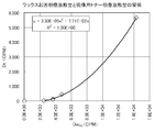
- FIG. 1 is a graph showing the relationship between the wax-induced dust emission amount (Dw All ) and the electrostatic charge image developing toner dust emission amount (Dt).
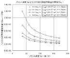
- FIG. 2 is a graph showing the relationship between the wax-induced dust emission amount (Dw All ) and the dust emission rate (Vd).
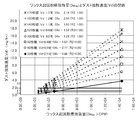
- FIG. 3 is a graph showing the relationship between the print speed (Vp) and the amount of wax-induced dust emission (Dw All ).
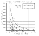
- FIG. 4 is a graph showing the relationship between the dust emission amount (Dt) of the electrostatic image developing toner and the dust emission speed (Vd) generated from the image forming apparatus.
- FIG. 5 is a graph showing the relationship between the printing speed (Vp) and the upper limit (DtL) of toner dust emission.
- the horizontal axis indicates each A4 horizontal conversion printing speed (Vp), and the vertical axis indicates the upper limit (DtL) of toner dust emission.
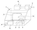
- FIG. 6 is a diagram showing a schematic configuration of the dust detection and measurement device.
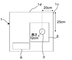
- FIG. 7 is an explanatory diagram showing a specific size of the draft 1 of the dust detection and measurement apparatus shown in FIG. FIG.
- FIG. 8 is a plan view of a part of the inside of the dust detection and measurement apparatus shown in FIG. 6 as viewed from above.
- 9 shows the positional relationship in the height direction of the heating device (hot plate) 2, the sample cup (aluminum cup) 3 and the cone collector 10 in the dust detection measuring apparatus shown in FIG. It is a figure explaining the magnitude
- FIG. FIG. 10 shows “a region where the toner for developing an electrostatic charge image has a higher abundance ratio of the wax component Y than that of the wax component X, and the region is more on the outer side than the center side of the toner for developing an electrostatic image”. It is a schematic diagram showing the specific example of a state.
- developer toner The method for producing the electrostatic image developing toner of the present invention (hereinafter sometimes abbreviated as “developing toner” or “toner”) is not particularly limited. In the manufacturing method, the configuration described below may be employed.
- the present invention relates to an electrostatic charge image developing toner containing a binder resin, a colorant and a wax, and the melting point of the wax contained in the electrostatic charge image developing toner is 55 ° C. or higher and 90 ° C. or lower.
- the electrostatic image developing toner is characterized in that at least one point is present and the electrostatic charge image developing toner has a dust diffusing amount (Dt) satisfying the following formula (1).
- Dt represents the amount of dust emitted when the toner is heated in a static environment (CPM (measured value per minute: Counter Per Minute)
- Vp is A4 horizontal conversion in the image forming apparatus. Represents the printing speed (sheets / minute). However, Vp is 171.2 or less.
- the toner dust means a substance that is released from the toner when the toner is heated
- the toner dust diffusing amount (Dt) is the electrostatic charge image developing toner from the dust measuring device (manufactured by SIBATA). It is a value measured by a method described in Examples described later with a digital dust meter LD-3K2).
- An image forming apparatus in Vp represents a printer, a copier, a facsimile, or the like.
- the printing speed (sheets / minute) in A4 horizontal conversion for standardizing Vp represents the number of sheets that can be printed per minute when printing in the minor axis direction of a paper having an A4 size paper size. .
- A4 horizontal is 210 mm.
- the wax has a melting point of the wax contained in the toner (hereinafter, simply referred to as a melting point of the wax) of 90 ° C. or less in order to impart satisfactory fixing properties to the toner for developing an electrostatic image. It is essential to include the wax. This is because a wax having a too high melting point has a sufficient releasing property because the diffusion rate from the inside of the toner becomes slow when the toner is melted by the fixing device, even if the sublimation energy is low. This is because performance cannot be imparted.
- a wax having a melting point that is too low can cause a decrease in the heat resistance of the toner, and may not be used because it may cause problems such as blocking during transportation, and includes a wax having a melting point of 55 ° C. or higher. Things are essential.
- the melting point of the wax itself is 55 ° C. or higher and 90 ° C. or lower.
- the melting point of the wax in the state where it is contained in the toner for developing an electrostatic image is determined by the method described in the examples described later; relaxation of enthalpy accompanying the glass transition point of the resin in the toner using a thermal analyzer (DSC). It is a value measured in a state where the peak (thermal history) derived from is lost.
- the value 101 on the left side of Equation (1) is the lower limit value of the amount of toner dust diffusing (Dt) that does not cause hot offset. That is, when the electrostatic charge image developing toner has a dust emission amount (Dt) of less than 101, the electrostatic charge image developing toner electrostatically adhering to the paper surface is mainly wax that sublimates to the fixing roller surface. When the absolute amount of the releasable component is too small, sufficient offset release ability cannot be imparted to cause hot offset.
- the lower limit value of the toner dust diffusing amount (Dt) that does not generate hot offset is a value obtained by multiplying the measured hot offset value by the measurement accuracy of the dust measuring device.
- the measured value that does not generate an offset is the amount of dust diffused under a predetermined condition using a dust measurement device (SIBATA digital dust meter LD-3K2) in the dust detection and measurement device shown in the examples described later. It is a value that does not cause hot offset when actually measured. Also, the speed accuracy of the dust measuring device is multiplied to take into account the measurement accuracy of the dust measuring device.
- SIBATA digital dust meter LD-3K2 a dust measurement device
- the amount of dust diffusing (Dt) of toner that does not cause hot offset was 112 (CPM) (for example, Example 3).
- CCM the amount of dust diffusing
- the toner dust that does not cause hot offset A numerical value of 101 obtained by multiplying the amount of diffusion (Dt) 112 by 0.9 was taken as the lower limit value of the amount of toner dust emission.
- the dust emission amount (Dt) of the toner is, for example, a dust detection / measurement device disclosed in Japanese Patent Application Laid-Open No. 2010-2338, and the amount of dust diffused using the dust detection / measurement device. Can be measured using a dust measuring device (digital dust meter LD-3K2 manufactured by SIBATA).
- Equation (1) indicates the amount of dust dust that is required to reduce the amount of dust generated per hour (dust emission rate: Vd) to 3.0 or less when continuously printed by the image forming apparatus. It is determined from the upper limit (DtL).
- the mathematical formula of 195,449 / Vp-1,040 worth on the right side is obtained from the measured values of the dust emission amount (Dt) and the dust emission rate (Vd) of the electrostatic image developing toner measured under the conditions shown in the examples. This is an inevitable function.
- the lower limit value shown on the left side of Equation (1) varies depending on the environment in which dust is diffused from the toner and the dust detection and measurement device, and the amount of dust generated per hour when the image forming apparatus performs continuous printing (dust emission speed: Vd ) Changes the numerical value shown on the right side of equation (1). If the environment in which dust is scattered from the toner and the dust detection / measurement apparatus are the same, even if the image forming apparatus has a different printing speed (Vp), if the condition of the expression (1) is satisfied, Generation of hot offset can be suppressed while suppressing generated dust.
- FIG. 4 is a graph showing the relationship between the dust emission amount (Dt) of the electrostatic image developing toner and the dust emission speed (Vd) generated from the image forming apparatus.
- the horizontal axis shows the amount of dust emission (Dt) generated when the toner is heated in a static environment, and the vertical axis shows the amount of dust generated per hour when the image forming apparatus performs continuous printing (dust emission speed). : Vd).
- the amount of dust (dust emission rate: Vd) is measured by the method of the example described later, with respect to the dust collected according to the blue angel mark certified measurement method (RAL UZ122 2006).
- an image forming apparatus that prints a large number of sheets per unit time consumes a larger amount of electrostatic charge image developing toner, resulting in an increase in the amount of dust generated per unit time.
- Vd Denst diffusion speed
- the dust emission amount (Dt) of the electrostatic image developing toner continuously printed at a printing speed of 36 sheets / min, and the amount of dust generated from the image forming apparatus using the electrostatic image developing toner (dust emission rate: Vd) is obtained by proportionally calculating the amount of dust (dust emission rate: Vd) generated from the image forming apparatus when the printing speed increases or decreases, and connecting the calculated values in a linear form by the least square method.
- the measured value of the dust emission amount (Dt) of the electrostatic charge image developing toner is 5,665 (CPM).
- the electrostatic charge image developing toner is used to increase the printing speed in A4 horizontal conversion to 120 sheets / min
- the amount of dust generated from the image forming apparatus using the developing toner dust emission speed: Since Vd) is proportional to the increased printing speed, (120/36)
- ⁇ 3.7 12.3 (mg / hr).
- the solid line indicates the measured amount of toner dust (Dt) measured at a printing speed of 36 sheets / min in A4 horizontal conversion from the examples and comparative examples described later, and an image forming apparatus using this toner.
- Each measurement result is connected in a linear form using the least square method from the dust emission rate (Vd) generated per hour.
- the dotted line is a proportional calculation of the amount of dust (dust emission rate: Vd) generated from the image forming apparatus as the printing speed increases / decreases from the measured results, and the toner dust emission amount (Dt) and image at each printing speed (Vp). It represents the relationship between the dust emission rate (Vp) generated from the forming apparatus.
- a horizontal line of Vd 3.0 is drawn.
- the horizontal axis value of the coordinate of the intersection of the dotted line and the solid line connecting the relationship between the toner dust emission amount (Dt) and the dust emission rate (Vd) generated from the image forming apparatus is linear.
- the upper limit (DtL) of toner dust emission when the dust emission rate (Vd) is a specific value of 3.0 or less is shown.
- FIG. 5 shows each printing speed (Vp) on the horizontal axis and the upper limit (DtL) of the toner dust emission amount on the vertical axis.
- Vp printing speed
- DtL upper limit
- the amount of dust generated per hour (dust emission rate: Vd) when continuous printing is performed by the image forming apparatus is preferably smaller, and the preferable dust emission rate (Vd) satisfies a specific value of 1.8 or less.
- the amount of dust diffusing (Dt) from the electrostatic image developing toner satisfies the formula (2). 101 ⁇ Dt ⁇ 117,262 / Vp ⁇ 1,039 (2)
- Formula (2) is a requirement for setting the amount of dust generated per hour from the image forming apparatus (dust emission rate: Vd) to be 1.8 or less which is a suitable specific value, and formula (1) is determined.
- the function is inevitably obtained from the measured values of the dust diffusing amount (Dt) and the dust diffusing speed (Vd) of the electrostatic image developing toner as shown in the embodiment.
- the horizontal axis value of the point of intersection with the connected dotted line indicates the upper limit (DtL) of toner dust emission when the dust emission rate (Vd) is set to a specific value of 1.8 or less. Then, as shown in FIG. 5, the value of each printing speed (Vp) on the horizontal axis and the value of each toner dust emission amount upper limit (DtL) on the vertical axis are indicated by ⁇ (triangle) dots, and indicated by these ⁇ dots.
- Dt should satisfy Expression (3). More preferred. 101 ⁇ Dt ⁇ 71,653 / Vp ⁇ 1,039 (3)
- Formula (3) is a requirement for setting the amount of dust generated per hour from the image forming apparatus (dust release rate: Vd) to be 1.1 or less which is a suitable specific value, and formula (1) is determined.
- the function is inevitably obtained from the measured values of the dust diffusing amount (Dt) and the dust diffusing speed (Vd) of the electrostatic image developing toner as shown in the embodiment.
- the horizontal axis value of the point of intersection with the connected dotted line indicates the upper limit (DtL) of toner dust emission when the dust emission rate (Vd) is a specific value of 1.1 or less.
- the value of each printing speed (Vp) on the horizontal axis and the value of the upper limit (DtL) of each toner dust emission amount on the vertical axis are indicated by ⁇ (square) dots, and are indicated by these ⁇ dots.
- toner dust emission amount upper limit DtL 71,653 / Vp-1,039 . This is the relationship of the upper limit (DtL) of the toner dust emission amount at each printing speed (Vp) corresponding to the right side of Expression (3).
- the toner dust emission amount (Dt) is It is particularly preferable that the formula (4) is satisfied. 101 ⁇ Dt ⁇ 52,104 / Vp-1,039 (4)
- Expression (4) is a requirement for setting the amount of dust generated per hour from the image forming apparatus (dust emission rate: Vd) to a suitable specific value of 0.8 or less, and determines Expression (1).
- the function is inevitably obtained from the measured values of the dust diffusing amount (Dt) and the dust diffusing speed (Vd) of the electrostatic image developing toner as shown in the embodiment.
- the horizontal axis value of the point of intersection with the connected dotted line represents the upper limit (DtL) of toner dust emission when the dust emission rate (Vd) is set to a specific value of 0.8 or less.
- the value of each printing speed (Vp) on the horizontal axis and the value of each toner dust emission upper limit (DtL) on the vertical axis are indicated by ⁇ (diamond) dots, and indicated by these ⁇ dots.
- the selection and addition amount of wax, binder resin, colorant, external additive, and other substances may be adjusted.
- the main factor of dust is wax
- the dust emission amount Dt of the electrostatic charge image developing toner is expressed by the above formula (1). It can be adjusted to be in the range.
- the dust emission amount Dt in order for the dust emission amount Dt to satisfy the range of the formula (2), it is necessary to select a wax that generates less dust than the wax selected in the formula (1) or reduce the amount of added wax. preferable. Further, in order for the dust emission amount Dt to satisfy the range of the formula (3), it is preferable to select a wack that generates less dust than the wax selected in the formula (2) or to reduce the amount of added wax. . Furthermore, in order for the dust emission amount Dt to satisfy the equation (4), it is preferable to select a wax that generates less dust than the wax selected in the equation (3) or to reduce the amount of added wax.
- the electrostatic image developing toner satisfying the formula (2) is faster than the electrostatic image developing toner satisfying the formula (1) by the image forming apparatus (the printing speed per unit time is faster). ) Can be said to be more preferable from the viewpoint of reducing the dust diffusion rate.
- the electrostatic charge image developing toner satisfying the formula (3) rather than the electrostatic charge image developing toner satisfying only the expressions (1) and (2) satisfies the electrostatic charge image development satisfying the expressions (1) to (3).
- the toner for developing an electrostatic charge image satisfying the formula (4) is more preferable than the toner for use from the viewpoint that the image forming apparatus can reduce the dust diffusing speed with a high-speed machine (the printing speed per unit time is fast). .
- the electrostatic charge image developing toner may be obtained according to the following method (I) or (II).
- A) to (c) are satisfied.
- the electrostatic image developing toner contains at least two types of waxes, ie, a wax component X and a wax component Y.
- the dust emission amount of the wax component Y is larger than the dust emission amount of the wax component X.
- the content of the wax component X is larger than the content of the wax component Y.
- A), (b) and (e) are satisfied.
- the electrostatic image developing toner contains at least two types of waxes, ie, a wax component X and a wax component Y.
- the dust emission amount of the wax component Y is larger than the dust emission amount of the wax component X.
- E The balance between the amount of wax dust emission and the content of the wax component X and the wax component Y is adjusted.
- Dw All represents the amount of wax-induced dust emission, and is a value derived by calculation. If all the wax components contained in the toner have been emitted, how much the emission amount will be. The value to represent. That is, it is the product of the amount of radiation when the wax alone is diffused and the content of the wax in the toner of the amount of radiation emitted. When a plurality of waxes are present in the toner, such as the wax component X and the wax component Y, the sum of the products is Dw All .
- the definition and measuring method of the amount of wax dust emission are as described in the examples.
- the concentration of the wax in the toner for developing an electrostatic image can be calculated from the formulation of the wax.
- the horizontal axis represents the value of each Dw All (CPM), and the vertical axis represents Dt (generated when the electrostatic charge image developing toner is heated).
- Fig. 1 shows the dust emission per minute).
- FIG. 3 is a graph in which the maximum value of Dw All at the intersection is plotted on the vertical axis and the printing speed Vp at that time is plotted on the horizontal axis.
- Dt and Dw All are correlated and determined uniquely, so FIG. 3 is the same as that obtained by converting Dt in FIG. 5 described later to Dw All .
- FIG. 3 shows a very good correlation since Dw All is in the form of a function inversely proportional to Vp and the square of the correlation coefficient is 1.00 as in FIG. That is, when the printing speed of the designed image forming apparatus is determined, an upper limit value of the wax-induced dust emission amount Dw All can be derived for each allowable value of the dust generation speed Vd from the image forming apparatus.
- the qualitative direction for the dust image diffusion amount Dt of the charge image developing toner to satisfy the range of the above formula (1) is shown below.
- A When the amount of wax dust diffusing is large, the hot offset resistance (HOS) is improved, while the dust generation speed Vd from the image forming apparatus is increased.
- B When the wax content is high, the HOS is improved, but the dust generation speed Vd from the image forming apparatus is increased.
- C If the amount of wax dust is too small, the HOS will deteriorate, but the dust generation speed Vd from the image forming apparatus will decrease.
- D If the wax content is too low, the HOS will deteriorate, but the dust generation rate Vd from the image forming apparatus will decrease.
- the toner according to the present invention it is important to control the dust generation amount Dt from the toner.
- the maximum amount allowed to achieve a dust generation rate (Vd) of 3.0 mg / hr or less from the image forming apparatus with respect to the wax-induced dust emission amount (Dw All ) is determined.
- the maximum allowable wax can be obtained by the following procedure.
- (A-1) Vp is set to an arbitrary value.
- (A-3) Dust emission amount (Dw) of wax to be used is measured by the method described in the examples.
- the maximum allowable wax concentration that can be contained in the toner can be obtained.
- the dust generation amount Dt from the toner according to the present invention is less than 101, and the HOS deteriorates when sufficient releasability cannot be imparted to the fixing roller. Therefore, it is essential to design Dt to be 101 or more.
- Dt and Dw All have the relationship of the above formula (6).
- Dw All is uniquely determined.
- Cw can be obtained.
- Cw obtained here is the minimum wax content when an arbitrary wax is selected.
- the minimum allowable wax can be obtained by the following procedure.
- (B-1) Substitute 101 for Dt in equation (6) to obtain Dw All .
- (Dw All 3,272)
- (B-2) Dust emission amount Dw of the wax used is measured by the method described in the examples.
- the minimum wax content for preventing HOS from being deteriorated can be obtained.
- the electrostatic image developing toner satisfying any of the ranges (2) to (4) in which the dust emission amount Dt is satisfied is the electrostatic image developing toner having a shell core structure in the method (I).
- the shell material contains the wax component Y
- the core material contains the wax component X.
- the wax component X and the wax component Y are dispersed in the entire toner base particles before adding the wax to the polymer primary particles, which will be described later, and forming the toner for developing an electrostatic image. Is obtained. It is necessary that the dust content of the wax component X and the wax component Y and the content in the toner satisfy the above-described relationship.
- the developing toner of the present invention is measured in accordance with the method described in ⁇ Method and definition of wax melting point in the state of being included in the electrostatic charge developing toner> in the example.
- the melting point of the wax can be determined.
- the developing toner of the present invention is a toner in which at least one melting point of the wax in a state contained in the toner exists at 55 ° C. or more and 90 ° C. or less.
- the developing toner of the present invention obtained by the above methods (I) and (II) is a wax in the state contained in the toner according to the method for measuring the melting point of wax in the state contained in the toner.
- the toner preferably has a melting point of at least one point at 55 ° C. or more and less than 70 ° C. and one point at 70 ° C. or more and 80 ° C. or less.
- the developing toner of the present invention is a high-speed machine that consumes a large amount of toner for developing an electrostatic image per unit time, or when the amount of electrostatic image developing toner on the paper for graphic use increases. It is suitable for high-speed printing because it can improve the hot offset resistance while suppressing dust generated during fixing. Among these, the above effect is particularly exerted in a high-speed machine having a printing speed (Vp) of 20 (sheets / minute) or more, more preferably a printing speed (Vp) of 30 (sheets / minute) or more.
- the method for producing the toner for developing an electrostatic charge image of the present invention is not particularly limited, and the construction described below may be adopted in the method for producing a wet method toner or a pulverization method toner.
- the binder resin constituting the toner of the present invention may be appropriately selected from those known to be usable for toner.
- styrene resin vinyl chloride resin, rosin modified maleic acid resin, phenol resin, epoxy resin, saturated or unsaturated polyester resin, polyethylene resin, polypropylene resin, ionomer resin, polyurethane resin, silicone resin, ketone resin, Ethylene-acrylate copolymer, xylene resin, polyvinyl butyral resin, styrene-alkyl acrylate copolymer, styrene-alkyl methacrylate copolymer, styrene-acrylonitrile copolymer, styrene-butadiene copolymer, styrene-anhydrous malein An acid copolymer etc. can be mentioned. These resins can be used alone or in combination.
- the colorant constituting the toner of the present invention may be appropriately selected from those known to be usable for toner.
- yellow pigments, magenta pigments, and cyan pigments shown below can be used.
- black pigments carbon black or a mixture of the following yellow pigments / magenta pigments / cyan pigments toned to black is used. .
- carbon black as a black pigment exists as an aggregate of very fine primary particles, and when dispersed as a pigment dispersion, particle coarsening due to reaggregation tends to occur.
- the degree of reagglomeration of carbon black particles correlates with the amount of impurities contained in carbon black (the degree of residual undecomposed organic matter). If there are many impurities, coarsening due to reaggregation after dispersion tends to be severe. Indicates.
- the ultraviolet absorbance of the toluene extract of carbon black measured by the following method is preferably 0.05 or less, and more preferably 0.03 or less.
- the carbon black of the channel method tends to have a large amount of impurities, and therefore, the carbon black in the present invention is preferably one produced by the furnace method.
- a commercially available spectrophotometer for example, an ultraviolet-visible spectrophotometer (UV-3100PC) manufactured by Shimadzu Corporation can be used.
- yellow pigment compounds represented by condensed azo compounds, isoindolinone compounds and the like are used. Specifically, C.I. I. CI Pigment Yellow 12, 13, 14, 15, 17, 62, 74, 83, 93, 94, 95, 109, 110, 111, 128, 129, 147, 150, 155, 168, 180, 194, etc. are preferably used. It is done.
- magenta pigment condensed azo compounds, diketopyrrolopyrrole compounds, anthraquinones, quinacridone compounds, basic dye lake compounds, naphthol compounds, benzimidazolone compounds, thioindigo compounds, and perylene compounds are used.
- C.I. I. Pigment Red 2, 3, 5, 6, 7, 23, 48: 2, 48: 3, 48: 4, 57: 1, 81: 1, 122, 144, 146, 166, 169, 173, 184, 185, 202, 206, 207, 209, 220, 221, 238, 254, C.I. I. Pigment Violet 19 or the like is preferably used.
- a quinacridone pigment represented by pigment violet 19 is particularly preferred.
- the quinacridone pigments C.I. I.
- a compound represented by CI Pigment Red 122 is particularly preferable.
- cyan pigment copper phthalocyanine compounds and derivatives thereof, anthraquinone compounds, basic dye lake compounds, and the like can be used. Specifically, C.I. I. Pigment blue 1, 15, 15: 1, 15: 2, 15: 3, 15: 4, 60, 62, 66 and the like; I. Pigment Green 7, 36, etc. can be used particularly preferably.
- a wet method for obtaining a toner in an aqueous medium a method of performing radical polymerization in an aqueous medium such as a suspension polymerization method or an emulsion polymerization aggregation method (hereinafter abbreviated as “polymerization method”), Abbreviated as “legal toner”), chemical pulverization method, and the like are preferably used.
- a suspension polymerization method in a conventional polymerization toner production process a method in which a high shear force is applied in the process of generating polymerizable monomer droplets or a dispersion stabilizer or the like is increased. .
- any of the production methods such as the above-described suspension polymerization method, polymerization method such as emulsion polymerization aggregation method and chemical pulverization method can be used.
- the toner is prepared from a size larger than the toner base particle size to a smaller size. Therefore, when trying to reduce the average particle size, the particle size ratio on the small particle side tends to increase, and an excessive burden such as a classification step is forced.
- the emulsion polymerization agglomeration method has a relatively sharp particle size distribution and is prepared from a size smaller than the toner base particle size to a larger particle, and thus is prepared without going through a classification step or the like. A toner having a particle size distribution is obtained.
- a classification step is usually essential for a pulverized toner
- a desired particle size distribution can be obtained with a wet method toner even without classification, particularly by an emulsion polymerization aggregation method.
- toner manufactured by the emulsion polymerization aggregation method in which radical polymerization is performed in an aqueous medium particularly preferable in the present invention will be described in more detail among the manufacturing methods of the polymerized toner.
- a toner When a toner is produced by an emulsion polymerization aggregation method, it usually has a polymerization process, a mixing process, an aggregation process, an aging process, and a washing / drying process. That is, generally, a dispersion liquid containing primary polymer particles obtained by emulsion polymerization is mixed with a dispersion liquid such as a colorant, a charge control agent, and wax, and the primary particles in the dispersion liquid are aggregated to form particle aggregates.
- the toner base particles can be obtained by collecting and collecting the particles obtained by fusing the fine particles or the like after the collection, and if necessary, by washing and drying.
- the polymer primary particle dispersion that becomes the shell material is added to and held in the core formed through the core material aggregation process by polymerization, mixing, and aggregation, and then rounded.
- the shell core structure can be formed by the process and the washing and drying process.
- the binder resin constituting the polymer primary particles used in the emulsion polymerization aggregation method one or more polymerizable monomers that can be polymerized by the emulsion polymerization method may be appropriately used.
- a polymerizable monomer having a Bronsted acidic group hereinafter sometimes simply referred to as “acidic monomer” or Bronsted.
- a polymerizable monomer having a basic group hereinafter, sometimes simply referred to as “basic monomer” and a polymerizable monomer having neither a Bronsted acidic group nor a Bronsted basic group (hereinafter, “ It is preferable to use “other monomers” as raw material polymerizable monomers.
- each polymerizable monomer may be added separately, or a plurality of polymerizable monomers may be mixed in advance and added simultaneously.
- the polymerizable monomer may be added as it is, or may be added as an emulsion prepared by mixing with water or an emulsifier in advance.
- the “acidic monomer” examples include polymerizable monomers having a carboxyl group such as acrylic acid, methacrylic acid, maleic acid, fumaric acid and cinnamic acid, polymerizable monomers having a sulfonic acid group such as sulfonated styrene, and vinylbenzenesulfonamide. Examples thereof include polymerizable monomers having a sulfonamide group.
- Examples of the “basic monomer” include aromatic vinyl compounds having an amino group such as aminostyrene, nitrogen-containing heterocyclic-containing polymerizable monomers such as vinylpyridine and vinylpyrrolidone, and amino groups such as dimethylaminoethyl acrylate and diethylaminoethyl methacrylate. Examples include (meth) acrylic acid esters.
- acidic monomers and basic monomers may be used alone or in combination, and may exist as a salt with a counter ion.
- an acidic monomer more preferably acrylic acid and / or methacrylic acid.
- the total amount of acidic monomer and basic monomer in 100% by mass of the total polymerizable monomer constituting the binder resin as the polymer primary particles is preferably 0.05% by mass or more, more preferably 0.5% by mass or more. More preferably, it is 1% by mass or more.
- the upper limit is preferably 10% by mass or less, more preferably 5% by mass or less.
- “Other monomers” include styrenes such as styrene, methylstyrene, chlorostyrene, dichlorostyrene, p-tert-butylstyrene, pn-butylstyrene, pn-nonylstyrene, methyl acrylate, acrylic acid Acrylic esters such as ethyl, propyl acrylate, n-butyl acrylate, isobutyl acrylate, hydroxyethyl acrylate, ethylhexyl acrylate, methyl methacrylate, ethyl methacrylate, propyl methacrylate, n-butyl methacrylate, methacryl Methacrylates such as isobutyl acid, hydroxyethyl methacrylate, ethylhexyl methacrylate, acrylamide, N-propylacrylamide, N, N-dimethylacrylamide, N
- an acidic monomer and other monomers may be used in combination. More preferably, acrylic acid and / or methacrylic acid is used as the acidic monomer, and a polymerizable monomer selected from styrenes, acrylic esters, and methacrylic esters is used as the other monomer, and more preferably.
- a cross-linked resin when used as the binder resin constituting the polymer primary particles, a polyfunctional monomer having radical polymerizability is used as the cross-linking agent shared with the above-mentioned polymerizable monomer, for example, divinylbenzene, hexane.
- examples include diol diacrylate, ethylene glycol dimethacrylate, diethylene glycol dimethacrylate, diethylene glycol diacrylate, triethylene glycol diacrylate, neopentyl glycol dimethacrylate, neopentyl glycol acrylate, and diallyl phthalate.
- a polymerizable monomer having a reactive group in a pendant group such as glycidyl methacrylate, methylol acrylamide, acrolein and the like.
- radical polymerizable bifunctional monomers are preferable, and divinylbenzene and hexanediol diacrylate are particularly preferable.
- polyfunctional monomers may be used alone or in combination.
- the blending ratio of the polyfunctional monomer in the total polymerizable monomer constituting the resin is preferably 0.005% by mass or more, more preferably 0. 0.1% by mass or more, more preferably 0.3% by mass or more, and the upper limit is preferably 5% by mass or less, more preferably 3% by mass or less, and still more preferably 1% by mass or less.
- emulsifiers can be used for the emulsion polymerization, but one or more emulsifiers selected from cationic surfactants, anionic surfactants and nonionic surfactants are used in combination. be able to.
- Examples of the cationic surfactant include dodecyl ammonium chloride, dodecyl ammonium bromide, dodecyl trimethyl ammonium bromide, dodecyl pyridinium chloride, dodecyl pyridinium bromide, hexadecyl trimethyl ammonium bromide and the like.
- anionic surfactant examples include fatty acid soaps such as sodium stearate and sodium dodecanoate, sodium dodecyl sulfate, sodium dodecylbenzenesulfonate, and sodium lauryl sulfate.
- Nonionic surfactants include, for example, polyoxyethylene dodecyl ether, polyoxyethylene hexadecyl ether, polyoxyethylene nonyl phenyl ether, polyoxyethylene lauryl ether, polyoxyethylene sorbitan monooleate ether, monodecanoyl sucrose Etc.
- the amount of the emulsifier is usually 1 to 10 parts by mass with respect to 100 parts by mass of the polymerizable monomer, and these emulsifiers include, for example, partially or fully saponified polyvinyl alcohol such as saponified polyvinyl alcohol, hydroxy One or more of cellulose derivatives such as ethyl cellulose can be used in combination as a protective colloid.
- polymerization initiator examples include hydrogen peroxide; persulfates such as potassium persulfate; organic peroxides such as benzoyl peroxide and lauroyl peroxide; 2,2′-azobisisobutyronitrile, 2, Azo compounds such as 2′-azobis (2,4-dimethylvaleronitrile); redox initiators and the like are used.
- persulfates such as potassium persulfate
- organic peroxides such as benzoyl peroxide and lauroyl peroxide
- 2,2′-azobisisobutyronitrile 2, Azo compounds such as 2′-azobis (2,4-dimethylvaleronitrile
- redox initiators and the like are used.
- One or more of them are usually used in an amount of about 0.1 to 3 parts by mass with respect to 100 parts by mass of the polymerizable monomer.
- it is preferable that at least a part or all of the initiator is hydrogen peroxide or organic peroxide
- one or more suspension stabilizers such as calcium phosphate, magnesium phosphate, calcium hydroxide, magnesium hydroxide and the like are usually added in an amount of 1 to 10 parts by mass with respect to 100 parts by mass of the polymerizable monomer. It may be used.
- the polymerization initiator and the suspension stabilizer may be added to the polymerization system at any time before, simultaneously with, and after the addition of the polymerizable monomer, and these addition methods are combined as necessary. May be.
- a known chain transfer agent can be used as necessary.
- a chain transfer agent include t-dodecyl mercaptan, 2-mercaptoethanol, diisopropyl xanthogen, four Examples thereof include carbon chloride and trichlorobromomethane.
- the chain transfer agent may be used alone or in combination of two or more, and is usually used in a range of 5% by mass or less based on the total polymerizable monomer.
- a pH adjuster, a polymerization degree adjuster, an antifoaming agent, etc. can be further mix
- the polymerizable monomers are polymerized in the presence of a polymerization initiator, and the polymerization temperature is usually 50 to 120 ° C., preferably 60 to 100 ° C., more preferably 70 to 90 ° C.
- the volume average diameter (Mv) of the polymer primary particles obtained by emulsion polymerization is usually 0.02 ⁇ m or more, preferably 0.05 ⁇ m or more, more preferably 0.1 ⁇ m or more, and usually 3 ⁇ m or less, preferably 2 ⁇ m or less. More preferably, the thickness is 1 ⁇ m or less.
- the volume average diameter (Mv) of the polymer primary particles is within the above range, the aggregation rate can be controlled relatively easily, and a toner having a desired particle diameter can be obtained.
- the glass transition temperature (Tg) of the binder resin constituting the polymer primary particles by DSC method is preferably 40 to 80 ° C.
- Tg glass transition temperature
- the acid value of the binder resin constituting the polymer primary particles is preferably 3 to 50 mgKOH / g, more preferably 5 to 30 mgKOH / g as a value measured by the method of JISK-0070 (1992).
- the colorant is not particularly limited as long as it is a commonly used colorant. Examples thereof include the pigments described above, carbon black such as furnace black and lamp black, and magnetic colorants.
- the content ratio of the colorant may be an amount sufficient for the obtained toner to form a visible image by development.
- the content is preferably in the range of 1 to 25 parts by mass, more preferably 1 to 15 parts by mass, particularly preferably 3 to 12 parts by mass.
- the colorant may have magnetism, and examples of the magnetic colorant include a ferromagnetic material exhibiting ferrimagnetism or ferromagnetism in the vicinity of 0 to 60 ° C., which is the use environment temperature of a printer, a copying machine, and the like.
- magnetite Fe 3 O 4
- maghemite ⁇ -Fe 2 O 3
- M x Fe 3-x O 4 M is Mg, Mn, Fe, Co, Ni, Cu, Zn, spinel ferrite represented by Cd, etc.
- BaO ⁇ 6Fe 2 O 3 , 6 -cubic ferrite such as SrO ⁇ 6Fe 2 O 3, Y 3 Fe 5 O 12, Sm 3 Fe 5 O garnet-type oxides such as 12, a magnetic rutile oxides such as CrO 2, and, Cr, Mn, Fe, Co, in the vicinity of 0 ⁇ 60 ° C. among such metals or their ferromagnetic alloys such as Ni It includes those shown.
- magnetite, maghematite, or an intermediate between magnetite and maghematite is preferable.
- the content of the magnetic powder in the toner is 0.2 to 10% by mass, preferably 0.5 to It is 8% by mass, more preferably 1 to 5% by mass.
- the content of the magnetic powder in the toner is usually 15% by mass or more, preferably 20% by mass or more, and usually 70% by mass or less, preferably 60% by mass or less. It is desirable. If the content of the magnetic powder is less than the above range, the magnetic force required for the magnetic toner may not be obtained, and if it exceeds the above range, fixing problems may be caused.
- a polymer primary particle dispersion and a colorant dispersion are mixed to form a mixed dispersion, and then aggregated to obtain a particle aggregate.
- the colorant is preferably used in the state of being emulsified in water by a mechanical means such as a sand mill or a bead mill in the presence of an emulsifier.
- the colorant dispersion is preferably added with 10 to 30 parts by weight of the colorant and 1 to 15 parts by weight of the emulsifier with respect to 100 parts by weight of water.
- the particle diameter of the colorant in the dispersion is monitored while being dispersed, and the volume average diameter (Mv) is finally set to 0.01 to 3 ⁇ m, more preferably 0.05 to 3 ⁇ m. It is preferable to control within the range of 0.5 ⁇ m.
- the number average diameter (Mn) is preferably 0.01 to 3 ⁇ m, more preferably 0.05 to 0.5 ⁇ m.
- the blend of the colorant dispersion at the time of emulsion aggregation is calculated and used so as to be 2 to 10% by mass in the finished toner base particles after aggregation.
- the wax contained in the developing toner of the present invention preferably contains at least two types of waxes and has a precise structure control. That is, it is preferable that the developing toner of the present invention satisfies the following requirements (a) to (c).
- the developing toner contains at least two types of waxes, ie, a wax component X and a wax component Y.
- the dust emission amount of the wax component Y is larger than the dust emission amount of the wax component X.
- the content of the wax component X is larger than the content of the wax component Y.
- the wax component X and the wax component Y represent two types of wax contained in the developing toner, and are synonymous with “wax X” and “wax Y”, respectively.
- the content of the wax component X is larger than the content of the wax component Y.
- the ratio in the wax component Y in all the wax components is 0.1 mass% or more and less than 10 mass%.
- the toner of the present invention preferably satisfies the following requirement (f).
- the toner for developing an electrostatic charge image has a region where the abundance ratio of the wax component Y is higher than that of the wax component X, and the region is more on the outer side than the center side of the toner for developing an electrostatic image. That is, when a wax having a small dust emission amount is used on the center side of the developing toner and a wax having a large dust emission amount is used on the outer side of the toner, both waxes are dispersed substantially uniformly in the toner. Compared to the case, the hot offset resistance is further improved.
- the wax is added for the purpose of imparting releasability of the developing toner from the fixing roller, but the wax having high sublimation property having high releasability is selectively used in the developing toner. It is considered that a higher concentration can be imparted when the toner is concentrated on the surface because the speed at which the wax diffuses from the developing toner during fixing is increased.
- the developing toner has a region in which the abundance ratio of the wax component Y is higher than that of the wax component X, and the region is outside the center side of the electrostatic charge image developing toner.
- the “more side” state is defined as follows. In other words, the state (f) is such that all of the core components present in the toner base particles cover 50% or more of the periphery with the shell component.
- FIG. 10 A specific example showing the state (f) is shown in FIG. 10, the white portion represents the core component, the white dotted line represents the periphery of the core component, the gray portion represents the shell component, and the black solid line represents the periphery of the shell component.
- the state of (f) is not limited to these.
- the abundance ratio of the wax component X and the wax component Y is determined by how the wax is charged during production. Therefore, in order to select a highly sublimable wax having a high releasability on the outer side of the developing toner and make it exist in a concentrated manner, it is possible to place more wax with a high sublimability in the shell component than in the core component. That's fine. Examples of the method include the methods described below. 1. Particles smaller than the core component are blended as a shell component. 2. The shell component is added after the core component. 3. When the toner is produced in a solvent containing water, the shell component uses a component having a higher polarity than the core component. 3. above.
- the highly polar component examples include a component containing a carboxyl group, a sulfonic acid group, a hydroxyl group, an amino group, or an alkoxy group. Above 1. ⁇ 3. One of these methods may be used, or a plurality of methods may be used in combination.
- the toner for developing an electrostatic charge image of the present invention has a core having a high abundance ratio of a wax having a small dust emission amount on the center side of the toner and a shell having a high abundance ratio of a wax having a large dust emission amount on the outer side of the toner. It is preferable to form a shell core structure.
- the wax contained in the shell material of the shell core structure substantially contains only the wax component Y, and the wax contained in the core material of the shell core structure is substantially It is more preferable to contain only the wax component X.
- the toner outer side has a region where the abundance ratio of the wax having a large dust emission amount is higher than the toner center side. Containing substantially only the wax component Y (or X) indicates that a trace amount of inevitable impurities may be mixed in addition.
- the inevitable impurities represent waxes other than the wax component Y (or X).
- the dust emission amount (Dw) of the wax component X is 50,000 CPM or less and the dust emission amount (Dw) of the wax component Y is 100,000 CPM or more. This is because the dust emission amount (Dw) of the wax component X existing on the center side of the toner is set to 50,000 CPM or less, so that the amount of dust generated per hour from the image forming apparatus (dust emission rate: Vd) is further increased. This is because it can be controlled to a low value, and higher hot offset resistance can be obtained by setting the dust emission amount (Dw) of the wax component Y present on the outer side of the toner to 100,000 CPM or more.
- the dust emission amount Dw of the wax component X or the wax component Y can be measured by the method described in the examples, similarly to the dust emission amount of the toner.
- “under static environment” refers to the conditions described in the examples, and the heating conditions are as described in the examples.
- examples of the wax component X having a small dust emission amount include hydrocarbon waxes and ester waxes. Among them, microcrystalline wax and ester wax having a large sublimation energy are preferably used from the viewpoint of suppressing the emission amount.
- the wax component Y having a large dust emission amount includes hydrocarbon waxes. Among them, paraffin wax having many linear molecules is preferably used from the viewpoint of imparting releasability.
- the developing toner of the present invention has a shell core structure, and polymer primary particles having a volume average diameter (Mv) enclosing wax of 50 nm or more and 500 nm or less are used as at least one of the shell materials.
- Mv volume average diameter
- the production method of the developing toner having the shell core structure of the present invention is not particularly limited, but is produced by any one of pulverization method, emulsion polymerization aggregation method, suspension polymerization method, and chemical pulverization method (melt suspension method). It is prepared by attaching shell fine particles prepared by emulsion polymerization method, mini-emulsion method, or coacervation method to the surface of the core particles, and then heat-sealing the shell and the core as necessary. I can do things.
- This shell core structure is advantageous in that it is advantageous in terms of releasability if the wax is arranged on the outer side, but if the wax is present on the outermost surface of the developing toner, it is satisfactory because it contaminates members such as the photoreceptor. This is because there are cases in which it is not possible to obtain a satisfactory image quality.
- the polymer primary particles encapsulated by the emulsion polymerization method, the mini-emulsion method, the coacervation method, or the like with the wax having the volume average diameter (Mv) as described above as the resin component are used as the shell material. It is preferable to use it as one.
- the polymer primary particles used as the shell material by the emulsion polymerization method it can be obtained in the same manner as the polymer primary particles obtained in the process of producing the toner by the emulsion polymerization aggregation method.
- the wax it is essential to include a wax having a melting point of 90 ° C. or lower in order to impart satisfactory fixability to the toner for developing an electrostatic image. This is because a wax having a too high melting point has a sufficient releasing property because the diffusion rate from the inside of the toner becomes slow when the toner is melted by the fixing device, even if the sublimation energy is low. This is because performance cannot be imparted. Furthermore, a wax having a melting point that is too low can cause a decrease in the heat resistance of the toner, and may not be used because it may cause problems such as blocking during transportation, and includes a wax having a melting point of 55 ° C. or higher. Things are essential. The melting point of the wax itself is 55 ° C.
- the melting point of the wax in the state where it is contained in the toner for developing an electrostatic image is determined by the method described in the examples described later; relaxation of enthalpy accompanying the glass transition point of the resin in the toner using a thermal analyzer (DSC). It is a value measured in a state where the peak (thermal history) derived from is lost.
- the wax used for producing the toner for developing an electrostatic charge image so as to have a value of the dust emission amount Dt (CPM) satisfying any of the formulas (1) to (4) described in the present specification
- Dt dust emission amount
- olefin wax paraffin wax
- ester wax having a long chain aliphatic group such as behenyl behenate, montanate ester, stearyl stearate
- water Plant waxes such as soy castor oil and carnauba wax
- ketones having long chain alkyl groups such as distearyl ketone
- silicones having alkyl groups higher fatty acids such as stearic acid
- long chain aliphatic alcohols such as eicosanol
- oleic acid amide, higher fatty acid amides such as stearic acid
- hydrocarbon-based (Fischer tropic wax, microcrystalline wax, polyethylene wax, polypropylene wax) wax and ester-based (long chain fatty acid and long chain alcohol ester or long chain fatty acid and polyhydric alcohol ester) wax are preferable.
- ester-based wax long chain fatty acid and long chain alcohol ester or long chain fatty acid and polyhydric alcohol ester
- the amount of the wax used may be that in which the toner forms a shell core structure, or the binder resin, the colorant, and the wax are included substantially uniformly without forming the shell core structure.
- the core material, the shell material, and the toner base material that does not form the shell core structure are preferably 4 to 30 parts by mass, more preferably 5 to 20 parts by mass of wax with respect to 100 parts by mass of the binder resin.
- the amount of wax used is less than the above range, it will be difficult to obtain satisfactory hot offset resistance due to insufficient release force, and if it is more than the above range, it may be difficult to suppress dust. Come. However, if the toner for developing an electrostatic charge image is produced by using the wax having the melting point range described in the present specification so that the dust emission amount Dt (CPM) described in the present specification is obtained, the amount of the wax used is particularly large. It is not limited at all.
- the wax exemplified above can be selected by selecting a wax component Y having a larger amount of dust emission than the wax component X. It can be used arbitrarily.
- the volume average diameter (Mv) in water is 0.01 to 2.0 ⁇ m, more preferably 0.01 to 1.0 ⁇ m, still more preferably 0.01 to 0.5 ⁇ m in water. It is preferable to add the wax dispersion emulsified and dispersed in the emulsion polymerization or in the aggregation step. In order to disperse the wax with a suitable dispersed particle diameter in the toner, it is preferable to add the wax as a seed during emulsion polymerization.
- polymer primary particles in which wax is encapsulated By adding as a seed, polymer primary particles in which wax is encapsulated can be obtained, so that a large amount of wax does not exist on the toner surface, and deterioration of toner charging property and heat resistance can be suppressed.
- the amount of wax present in the polymer primary particles is preferably calculated to be 4 to 30% by mass, more preferably 5 to 20% by mass, and particularly preferably 7 to 15% by mass.
- a charge control agent may be blended for imparting charge amount and charge stability.
- Conventionally known compounds are used as the charge control agent. Examples thereof include hydroxycarboxylic acid metal complexes, azo compound metal complexes, naphthol compounds, naphthol compound metal compounds, nigrosine dyes, quaternary ammonium salts, and mixtures thereof.
- the blending amount of the charge control agent is preferably in the range of 0.1 to 5 parts by mass with respect to 100 parts by mass of the resin.
- the charge control agent is blended with a polymerizable monomer or the like at the time of emulsion polymerization, or blended in the aggregation step with the polymer primary particles and the colorant, or the polymer. It can be blended by a method such as blending after the primary particles, the colorant and the like are agglomerated to obtain an appropriate particle size as a toner.
- the charge control agent is preferably emulsified and dispersed in water using an emulsifier, and used as an emulsion having a volume average diameter (Mv) of 0.01 ⁇ m to 3 ⁇ m.
- Mv volume average diameter
- the volume average diameter (Mv) of the polymer primary particles, the colorant dispersed particles, the wax dispersed particles, the charge control agent dispersed particles and the like in the dispersion is measured using a nanotrack by the method described in the Examples, It is defined as the measured value.
- the blended components such as the polymer primary particles, the colorant particles, and, if necessary, the charge control agent and the wax are mixed simultaneously or sequentially. It is possible to prepare a dispersion, that is, a polymer primary particle dispersion, a colorant particle dispersion, a charge control agent dispersion, and a wax fine particle dispersion, and mixing them to obtain a mixed dispersion. From the viewpoint of the property and uniformity of particle size.
- the agglomeration treatment usually includes a method of heating in a stirring tank, a method of adding an electrolyte, a method of combining these, and the like.
- the particle size of the particle agglomerates is controlled from the balance between the agglomeration force between the particles and the shearing force due to agitation.
- the cohesive force can be increased by heating or adding an electrolyte.
- any of organic salts and inorganic salts may be used. Specifically, NaCl, KCl, LiCl, Na 2 SO 4 , K 2 SO 4 , Li 2 SO 4 are used. , MgCl 2, CaCl 2, MgSO 4, CaSO 4, ZnSO 4, Al 2 (SO 4) 3, Fe 2 (SO 4) 3, CH 3 COONa, C 6 H 5 SO 3 Na and the like. Of these, inorganic salts having a divalent or higher polyvalent metal cation are preferred.
- the amount of the electrolyte blended varies depending on the type of electrolyte, target particle size, and the like, but is usually 0.05 to 25 parts by mass, preferably 0.1 to 15 parts per 100 parts by mass of the solid component of the mixed dispersion. Part by mass, more preferably 0.1 to 10 parts by mass.
- the blending amount is less than the above range, the progress of the agglutination reaction is slow, and fine powders of 1 ⁇ m or less remain after the agglomeration reaction, the average particle diameter of the obtained particle aggregate does not reach the target particle diameter, etc. There are cases.
- the upper limit of the above range is exceeded, rapid agglomeration tends to occur and it becomes difficult to control the particle size, and the resulting agglomerated particles may cause problems such as inclusion of coarse powder or irregular shapes. .
- a method of suppressing the amount of electrolyte may be employed as a method of controlling the particle size within a specific range of the present invention.
- the amount of the electrolyte is suppressed, the particle growth rate is slow, which is not industrially preferable in terms of production efficiency.
- the aggregation temperature when the electrolyte is added for aggregation is preferably 20 to 70 ° C., and more preferably 30 to 60 ° C.
- controlling the temperature before the aggregation step is one of the methods for controlling the particle size within a specific range.
- Some colorants added to the aggregating step also have the properties of the electrolyte, and may aggregate without adding the electrolyte. Therefore, the aggregation can be prevented by cooling the temperature of the polymer primary particle dispersion in advance when mixing the colorant dispersion. This aggregation easily generates fine powder and causes unevenness in the particle size distribution.
- the polymer primary particles are preferably cooled in advance in the range of preferably 0 to 15 ° C., more preferably 0 to 12 ° C., and still more preferably 2 to 10 ° C.
- the aggregation temperature in the case of performing aggregation only by heating without using an electrolyte is usually in the temperature range of (Tg ⁇ 20 ° C.) to Tg with respect to the glass transition temperature Tg of the polymer primary particles, and (Tg ⁇ 10 ° C.). ) To (Tg-5 ° C.).
- the time required for agglomeration is optimized depending on the shape of the apparatus and the processing scale, but in order to reach the target particle size, the toner base particles are usually held at a temperature within the above range for at least 30 minutes. It is desirable.
- the temperature rise until reaching the predetermined temperature may be raised at a constant rate, or may be raised stepwise.
- a toner primary particle having a shell core structure can be formed by adding (adhering or fixing) a polymer primary particle dispersion to the particle aggregate after the above-described aggregation treatment as necessary.
- the shell material preferably has a volume average particle size (Mv) of polymer primary particles containing or encapsulating wax of 50 nm to 500 nm, more preferably 80 nm to 450 nm, still more preferably 100 nm to 400 nm, particularly preferably 150 nm or more. It is preferable to include those having a thickness of 350 nm or less.
- Mv volume average particle size
- the shell agent can be efficiently attached to the core agent, and the amount of dust diffusing on the outer side of the toner.
- a region having a high abundance of wax is formed, a higher releasability can be imparted, and the amount of dust generated from the image forming apparatus per hour (dust emission rate: Vd) is controlled to a lower value. It becomes easy and higher hot offset resistance can be acquired.
- the electrostatic charge image developing toner has a shell core structure, and the core material having the shell core structure contains or contains only the wax component X, and has a volume average diameter (Mv) of 50 nm to 500 nm. It is also possible to include polymer primary particles having a volume average diameter (Mv) of 50 nm or more and 500 nm or less, in which only the wax component Y is contained or included in the shell material having the shell core structure. As preferred.
- the resin fine particles are usually used as a dispersion liquid dispersed in water or a liquid mainly composed of water with an emulsifier. However, when the charge control agent is added after the aggregation treatment, the resin fine particles are charged into the dispersion liquid containing the particle aggregates. It is preferable to add the resin fine particles after adding the control agent.
- an emulsifier and a pH adjuster are added as a dispersion stabilizer to reduce the cohesive force between the particles, thereby growing the toner base particles. It is preferable to add an aging step for causing fusion between the agglomerated particles after stopping.
- the toner of the present invention preferably has a sharp particle size distribution.
- the stirring rotational speed is reduced before the step of adding an emulsifier and a pH adjuster, that is, And a method of reducing the shearing force by stirring.
- the viscosity of the binder resin is lowered by heating to be circularized, but if heated as it is, the growth of the toner base particle size does not stop, so for the purpose of stopping the particle size growth by heating, usually as a dispersion stabilizer It is possible to apply a shearing force by adding an emulsifier or a pH adjuster or increasing the number of stirring revolutions.
- a toner having a specific particle size distribution can be obtained even if the stirring rotational speed is lowered to reduce the shearing force to the aggregated particles.
- the temperature of the aging step is preferably not less than Tg of the binder resin constituting the primary particles, more preferably not less than 5 ° C higher than the Tg, and preferably not more than 80 ° C higher than the Tg, more preferably The temperature is 50 ° C. or higher than Tg.
- the time required for the ripening step varies depending on the shape of the target toner, but is usually 0.1 to 10 hours, preferably 1 to 6 hours after reaching the glass transition temperature of the polymer constituting the primary particles. It is desirable to hold.
- the emulsifier used here one or more kinds of emulsifiers that can be used when producing the polymer primary particles can be selected and used, and particularly used when the polymer primary particles are produced. It is preferable to use the same emulsifier.
- the blending amount in the case of blending the emulsifier is not limited, but is preferably 0.1 parts by weight or more, more preferably 1 part by weight or more, further preferably 3 parts by weight or more with respect to 100 parts by weight of the solid component of the mixed dispersion. Moreover, it is preferably 20 parts by mass or less, more preferably 15 parts by mass or less, and still more preferably 10 parts by mass or less.
- the primary particles in the aggregate are fused and integrated, and the shape of the toner base particles as the aggregate becomes close to a spherical shape.
- the particle aggregate before the aging step is considered to be an aggregate due to electrostatic or physical aggregation of the primary particles, but after the aging step, the polymer primary particles constituting the particle aggregate are fused together.
- the shape of the toner base particles can be made nearly spherical. According to such a ripening step, by controlling the temperature and time of the ripening step, a cocoon shape in which primary particles are aggregated, a potato type in which fusion has progressed, a spherical shape in which fusion has further progressed, etc.
- Various shapes of toner can be produced according to the purpose.
- the particle aggregate obtained through each of the above steps is subjected to solid / liquid separation according to a known method, the particle aggregate is recovered, then washed as necessary, and then dried. Toner mother particles can be obtained.
- an outer layer mainly composed of a polymer is further formed on the surface of the particles obtained by the emulsion polymerization aggregation method by, for example, a spray drying method, an in-situ method, or a submerged particle coating method. It is also possible to form encapsulated toner base particles by forming them with a thickness of preferably 0.01 to 0.5 ⁇ m.
- the 50% circularity measured by using a flow type particle image analyzer FPIA-3000 is preferably 0.90 or more, more preferably 0.92 or more, and further Preferably it is 0.95 or more.
- FPIA-3000 manufactured by Malvern
- the average circularity is Preferably it is 0.995 or less, More preferably, it is 0.990 or less.
- At least one of the peak molecular weights in gel permeation chromatography (hereinafter sometimes abbreviated as “GPC”) of the tetrahydrofuran (THF) soluble content of the toner is preferably 10,000 or more, more preferably 1. 50,000 or more, more preferably 20,000 or more, preferably 100,000 or less, more preferably 80,000 or less, still more preferably 50,000 or less.
- GPC gel permeation chromatography
- the THF insoluble content of the toner is preferably 1% by mass or more, more preferably 2% by mass or more, and preferably 20% by mass or less, more preferably, when measured by a mass method by celite filtration. It is good that it is 10 mass% or less. If it is not within the above range, it may be difficult to achieve both mechanical durability and low-temperature fixability.
- the chargeability of the emulsion polymerization aggregation method toner may be positively charged or negatively charged.
- Control of the chargeability of the toner may include the selection and content of a charge control agent, the selection and blending amount of an external additive, etc. Can be adjusted by.
- the method for producing the pulverized toner is not particularly limited as long as it is a dust emission amount (CPM) described in the present application, and examples thereof include the following production method.
- CPM dust emission amount
- the resin used for producing the pulverized toner may be appropriately selected from those known to be usable for toner.
- styrene resin vinyl chloride resin, rosin modified maleic acid resin, phenol resin, epoxy resin, saturated or unsaturated polyester resin, ionomer resin, polyurethane resin, silicone resin, ketone resin, ethylene-acrylate copolymer, xylene Resin, polyvinyl butyral resin, etc. are used. These resins can be used alone or in combination.
- the polyester resin used in the production of the pulverized toner is composed of a polyhydric alcohol and a polybasic acid, and if necessary, at least one of these polyhydric alcohol and polybasic acid is a polyfunctional component (crosslinking component) having a valence of 3 or more. ) Containing a polymerizable monomer composition.
- examples of the divalent alcohol used for the synthesis of the polyester resin include ethylene glycol, diethylene glycol, triethylene glycol, 1,2-propylene glycol, 1,3-propylene glycol, 1,4-butanediol, neopentyl.
- Diols such as glycol, 1,4-butenediol, 1,5-pentanediol, 1,6-hexanediol, bisphenol A, hydrogenated bisphenol A, polyoxyethylenated bisphenol A, polyoxypropylenated bisphenol A, etc.
- Bisphenol A alkylene oxide adducts and others can be mentioned.
- a bisphenol A alkylene oxide adduct it is particularly preferable to use a bisphenol A alkylene oxide adduct as a main component monomer, and among them, an adduct having an average addition number of alkylene oxide of 2 to 7 per molecule is preferable.
- Examples of the trihydric or higher polyhydric alcohol involved in the crosslinking of polyester include sorbitol, 1,2,3,6-hexanetetrol, 1,4-sorbitan, pentaerythritol, dipentaerythritol, tripentaerythritol, Sugar, 1,2,4-butanetriol, 1,2,5-pentanetriol, glycerol, 2-methylpropanetriol, 2-methyl-1,2,4-butanetriol, trimethylolethane, trimethylolpropane, 1 , 3,5-trihydroxymethylbenzene and others.
- examples of the polybasic acid include maleic acid, fumaric acid, citraconic acid, itaconic acid, glutaconic acid, phthalic acid, isophthalic acid, terephthalic acid, cyclohexanedicarboxylic acid, succinic acid, adipic acid, sebacic acid, azelaic acid, malon.
- examples include acids, anhydrides of these acids, lower alkyl esters, alkenyl succinic acids such as n-dodecenyl succinic acid and n-dodecyl succinic acid, alkyl succinic acids, and other divalent organic acids.
- Examples of the tribasic or higher polybasic acid involved in the crosslinking of the polyester include 1,2,4-benzenetricarboxylic acid, 1,2,5-benzenetricarboxylic acid, 1,2,4-cyclohexanetricarboxylic acid, 2, 5,7-naphthalenetricarboxylic acid, 1,2,4-naphthalenetricarboxylic acid, 1,2,5-hexanetricarboxylic acid, 1,3-dicarboxyl-2-methyl-2-methylenecarboxypropane, tetra (methylenecarboxyl) Mention may be made of methane, 1,2,7,8-octanetetracarboxylic acid and anhydrides thereof.
- polyester resins can be synthesized by a usual method. Specifically, conditions such as reaction temperature (170 to 250 ° C.), reaction pressure (5 mmHg to normal pressure) and the like are determined according to the reactivity of the monomer, and the reaction is terminated when predetermined physical properties are obtained. .
- the softening point (Sp) of the polyester resin is preferably 90 to 135 ° C, and more preferably 95 to 133 ° C.
- the range of Tg is, for example, 50 to 65 ° C. when the softening point is 90 ° C. and 60 to 75 ° C. when the softening point is 135 ° C.
- Sp can be adjusted mainly by the molecular weight of the resin, and when the tetrahydrofuran soluble content of the resin is measured by the GPC method, the number average molecular weight is preferably 2000 to 20000, more preferably 3000 to 12000. Further, Tg can be adjusted mainly by selecting a monomer component constituting the resin.
- Tg can be increased by using an aromatic polybasic acid as a main component as an acid component. That is, among the polybasic acids described above, phthalic acid, isophthalic acid, terephthalic acid, 1,2,4-benzenetricarboxylic acid, 1,2,5-benzenetricarboxylic acid and the like, and anhydrides, lower alkyl esters, etc. thereof It is desirable to use it as a main component.
- Sp is defined as a value measured using a flow tester described in JIS K7210 (1999) and K6719 (1999). Specifically, using a flow tester (CFT-500, manufactured by Shimadzu Corporation), a plunger with an area of 1 cm 2 while heating a sample of about 1 g with a preheating time of 50 ° C. for 5 minutes and a heating rate of 3 ° C./min. A load of 30 kg / cm 2 is applied by pushing through a die having a hole diameter of 1 mm and a length of 10 mm. Thus, a plunger stroke-temperature curve is drawn, and when the height of the S-shaped curve is h, the temperature corresponding to h / 2 is defined as the softening point. Moreover, the measurement of Tg is defined as what was measured in accordance with the conventional method using the differential scanning calorimeter (DSC7 by Perkin-Elmer company, or DSC120 by Seiko Electronics Co., Ltd.).
- DSC7 differential scanning calorimeter
- the acid value of the polyester resin is 50 mgKOH / g. It is preferable to prepare the following amount, more preferably 30 mgKOH / g or less, and most preferably 3 to 15 mgKOH / g.
- the acid monomer component is previously converted into a lower alkyl ester by transesterification.
- Examples include a method of synthesizing using an acid group and a method of neutralizing residual acid groups by blending a basic component such as an amino group-containing glycol in the composition. It goes without saying that can be adopted.
- the acid value of the polyester resin is measured according to the method of JIS K0070 (1992). However, when the resin is difficult to dissolve in the solvent, a good solvent such as dioxane is used.
- the polyester resin is represented by the following formulas (i) to (iv) when the glass transition temperature (Tg) is plotted as an x-axis variable and the softening point (Sp) is plotted as a y-axis variable on the xy coordinates. Those having physical properties within a range surrounded by a straight line are preferred.
- the unit of Tg and Sp is “° C.”.
- Formula (i) Sp 4 ⁇ Tg ⁇ 110
- Formula (ii) Sp 4 ⁇ Tg ⁇ 170
- the pulverized toner When the polyester resin having the physical properties surrounded by the straight line represented by the above formulas (i) to (iv) is used for the pulverized toner, the pulverized toner is extremely resistant to mechanical stress and is continuously used. In some cases, the toner can be prevented from aggregating or solidifying due to frictional heat generated, and appropriate chargeability can be maintained over a long period of time.
- the pulverized toner is not particularly limited as long as it is a commonly used colorant.
- the colorant used for the above-described polymerized toner can be used.
- the content ratio of the colorant may be an amount sufficient for the obtained toner to form a visible image by development.
- the content is preferably in the range of 1 to 25 parts by mass in the same level as that of the polymerized toner. More preferably, it is 1 to 15 parts by mass, particularly preferably 3 to 12 parts by mass.
- the pulverized toner may contain other constituent materials.
- charge control agents can be used.
- charge control agents there are nigrosine dyes, amino group-containing vinyl copolymers, quaternary ammonium salt compounds, polyamine resins and the like for positive chargeability, and those containing metals such as chromium, zinc, iron, cobalt and aluminum for negative chargeability.
- Metal azo dyes, salts of salicylic acid or alkylsalicylic acid with the aforementioned metals, metal complexes and the like are known.
- the amount used is preferably from 0.1 to 25 parts by weight, more preferably from 1 to 15 parts by weight, based on 100 parts by weight of the resin.
- the charge control agent may be blended in the resin, or may be used in a form adhered to the surface of the toner base particles.
- charge control agents taking into account the charge imparting ability for the toner and color toner adaptability (the charge control agent itself is colorless or light color and has no color disturbance to the toner), it is an amino group for positive chargeability.
- vinyl-containing copolymers and / or quaternary ammonium salt compounds are preferred.
- metal salts and metal complexes of salicylic acid or alkylsalicylic acid with chromium, zinc, aluminum, boron, etc. are preferred.
- examples of the amino group-containing vinyl copolymer include copolymer resins of amino acrylates such as N, N-dimethylaminomethyl acrylate and N, N-diethylaminomethyl acrylate and styrene, methyl methacrylate and the like.
- examples of the quaternary ammonium salt compound include tetraethylammonium chloride, a salt-forming compound of benzyltributylammonium chloride and naphtholsulfonic acid, and the like.
- the above amino group-containing vinyl copolymer and the quaternary ammonium salt compound may be blended alone or in combination.
- the metal salt or metal complex of salicylic acid or alkylsalicylic acid among various known substances, chromium, zinc or boron complex of 3,5-ditertiary butylsalicylic acid is particularly preferable. Further, the above colorant and charge control agent may be subjected to a preliminary dispersion treatment, so-called master batch treatment, by pre-kneading with a resin in advance in order to improve dispersibility and compatibility in the toner.
- the pulverized toner preferably contains at least one fine particle additive on the surface of the particles. These are mainly intended to improve the adhesiveness, cohesiveness, fluidity and the like of the toner base particles, and improve the triboelectric chargeability and durability of the toner. Specific examples include organic and inorganic fine particles whose surface may have an average primary particle size of 0.001 to 5 ⁇ m, particularly preferably 0.002 to 3 ⁇ m, such as polyvinylidene fluoride and polytetrafluoroethylene.
- Fluorine resin powder fatty acid metal salts such as zinc stearate and calcium stearate, resin beads mainly composed of polymethyl methacrylate and silicone resin, minerals such as talc and hydrotalcite, silicon oxide, aluminum oxide, Examples thereof include metal oxides such as titanium oxide, zinc oxide, and tin oxide.
- silicon oxide fine particles are more preferable, and silicon oxide fine particles whose surfaces have been subjected to a hydrophobic treatment are particularly desirable.
- the hydrophobizing method include a method in which silicon oxide fine particles and organic silicon compounds such as hexamethyldisilazane, trimethylsilane, dimethyldichlorosilane, and silicone oil are reacted or physically adsorbed and chemically treated. .
- the BET specific surface area is preferably in the range of 20 to 200 m 2 / g.
- the mixing ratio of these fine particle additives to the pulverized toner is preferably in the range of 0.01 to 10% by mass, more preferably 0.05 to 5% by mass, based on the whole toner base particles.
- the wax in the pulverized toner is not particularly limited as long as the toner for developing an electrostatic charge image is produced so as to achieve the dust emission amount (CPM) described in the present application.
- CPM dust emission amount
- hydrocarbon-based (Fischer-Trofisch wax, microcrystalline wax, polyethylene wax, polypropylene wax) wax and ester-based (long chain fatty acid and long chain alcohol ester or long chain fatty acid and polyhydric alcohol ester) wax are preferable.
- hydrocarbon-based (Fischer-Trofisch wax, microcrystalline wax, polyethylene wax, polypropylene wax) wax and ester-based (long chain fatty acid and long chain alcohol ester or long chain fatty acid and polyhydric alcohol ester) wax are preferable.
- ester-based wax long chain fatty acid and long chain alcohol ester or long chain fatty acid and polyhydric alcohol ester
- Examples of the method for producing the pulverized toner include the following. 1. Resin, charge control substance, colorant and additives added as necessary are uniformly dispersed with a Henschel mixer or the like. 2. The dispersion is melt-kneaded with a kneader, an extruder, a roll mill or the like. 3. The kneaded product is roughly pulverized with a hammer mill, a cutter mill or the like, and then finely pulverized with a jet mill, an I-type mill or the like. 4). The finely pulverized product is classified with a dispersion classifier, a zigzag classifier or the like. 5. In some cases, silica or the like is dispersed in the classified product with a Henschel mixer or the like.
- the pulverized toner thus obtained is extremely resistant to mechanical stress, and can be prevented from agglomerating and solidifying due to frictional heat generated during continuous use, etc. Since a suitable chargeability can be maintained, it is particularly suitable as a toner for a non-magnetic one-component development system.
- the volume median diameter of the toner for developing an electrostatic charge image (hereinafter sometimes simply referred to as “Dv50”) is Beckman Coulter Multisizer III (aperture diameter 100 ⁇ m), and the dispersion medium is Isoton II manufactured by the same company. And disperse so that the dispersoid concentration is 0.03% by mass.
- the measurement particle size range is from 2.00 to 64.00 ⁇ m, and this range is discretized into 256 divisions at equal intervals on a logarithmic scale, and the volume calculated based on the statistical values on the basis of these volumes is the volume.
- the median diameter (Dv50) is defined. Moreover, what was calculated based on the statistical value on the basis of the number is defined as the number median diameter (Dn50).
- toner is obtained by blending “toner base particles” with an external additive or the like to be described later. Since the Dv50 is the Dv50 of “toner”, it is naturally measured according to the above method using “toner” as a measurement sample. However, since the Dv50 substantially the same as that of the toner is given even if the toner base particles before external addition are measured, not only the toner but also the volume median diameter (Dv50) of the toner base particles is measured by the above method.
- a wet method toner such as an emulsion polymerization aggregation method is dispersed in the dispersion medium before filtration / drying substantially in the dispersion medium Isoton II so that the dispersoid concentration is 0.03% by mass. Even if it is measured, the same Dv50 as that of the toner is given. Therefore, even when the toner base particles are in the state of a dispersion before filtration and drying, the measurement is performed by the above method.
- the toner base particles thus obtained may be made into a toner by mixing known external additives on the surface of the toner base particles in order to control fluidity and developability.
- External additives include metal oxides and hydroxides such as alumina, silica, titania, zinc oxide, zirconium oxide, cerium oxide, talc and hydrotalcite, titanium such as calcium titanate, strontium titanate and barium titanate.
- Examples thereof include acid metal salts, nitrides such as titanium nitride and silicon nitride, carbides such as titanium carbide and silicon carbide, and organic particles such as acrylic resins and melamine resins, and a plurality of them can be combined.
- silica, titania, and alumina are preferable, and those that have been surface-treated with, for example, a silane coupling agent or silicone oil are more preferable.
- the average primary particle diameter is preferably in the range of 1 to 500 nm, more preferably in the range of 5 to 100 nm. It is also preferable to use a combination of a small particle size and a large particle size in the particle size range.
- the total amount of the external additive is preferably in the range of 0.05 to 10 parts by mass, more preferably 0.1 to 5 parts by mass with respect to 100 parts by mass of the toner base particles.
- a value obtained by dividing Dv by Dn is preferably 1.0 to 1.25, more preferably 1.0 to 1.20, and still more preferably 1.0 to 1.15. A value close to 1.0 is desirable. Since the electrostatic charge image developing toner having a sharp particle size distribution tends to have uniform chargeability between the solid particles, the electrostatic charge image developing toner Dv / Dn for achieving high image quality and high speed. Is preferably in the above range.
- the toner for developing an electrostatic image of the present invention is a magnetic two-component developer in which a carrier for conveying the toner to the electrostatic latent image portion by a magnetic force coexists, or a magnetic toner containing a magnetic powder in the toner. It may be used for either a component developer or a non-magnetic one-component developer that does not use magnetic powder as a developer. In order to express the effect of the present invention remarkably, it is particularly preferable to use as a developer for a non-magnetic one-component development system.
- the carrier that is mixed with the toner to form the developer is a known magnetic substance such as an iron powder type, ferrite type, or magnetite type carrier, or a resin coating on the surface thereof.
- a magnetic resin carrier can be used.
- the carrier coating resin generally known styrene resins, acrylic resins, styrene acrylic copolymer resins, silicone resins, modified silicone resins, fluorine resins, and the like can be used, but are not limited thereto. It is not a thing.
- the average particle size of the carrier is not particularly limited, but preferably has an average particle size of 10 to 200 ⁇ m. These carriers are preferably used in an amount of 5 to 100 parts by mass with respect to 1 part by mass of the toner.
- the temperature was lowered from 121 ° C. to 10 ° C. at a rate of 10 ° C./min, and the temperature was maintained at 10 ° C. for 5 minutes. Further, the temperature was raised from 10 ° C. to 120 ° C. at a rate of 10 ° C./min, and the endothermic peak or shoulder temperature at the second temperature rise was taken as the melting point of the wax in the electrostatic charge developing toner. In other words, by observing the peak at the second temperature rise, the peak due to the enthalpy relaxation associated with the glass transition point of the resin in the toner disappears, and the melting point of the wax can be clearly observed. Time data was adopted as the melting point of the wax.
- the melting point of the wax alone was also measured in the same manner as described above except that the sample weight was 3.5 mg.
- the melting point of the wax in a state where it is contained in the toner for electrostatic charge development and the melting point of the wax alone or the wax mixture are different from each other with respect to the melting point and the temperature in the DSC measurement, for example, when the wax is different from the resin or the wax. Therefore, the melting point of the wax alone and the melting point of the wax when contained in the electrostatic charge developing toner were measured separately.
- volume average diameter (Mv) and number average diameter (Mn) of Pigment Dispersion, Polymer Primary Particle Dispersion, and Wax Dispersion The volume average diameter (Mv) and number average diameter (Mn) of the pigment dispersion and the polymer primary particle dispersion or wax dispersion are made by Nikkiso Co., Ltd., Model: Microtrac Nanotrac 150 (hereinafter abbreviated as “Nanotrack”). ) And according to the instruction manual of the nanotrack, the company's analysis software Microtrac Particle Analyzer Ver10.1.2. Using ⁇ 019EE, using ion-exchanged water having an electric conductivity of 0.5 ⁇ S / cm as a dispersion medium, the measurement was performed by the method described in the instruction manual under the following conditions or the following conditions, respectively.
- Solvent refractive index 1.333 -Measurement time: 100 seconds-Number of measurements: 1 time-Particle refractive index: 1.59 -Permeability: Transmission-Shape: True spherical shape-Density: 1.04
- Solvent refractive index 1.333 -Measurement time: 100 seconds-Number of measurements: 1 time-Particle refractive index: 1.59 -Permeability: Absorption-Shape: Non-spherical
- toner and a 20% DBS aqueous solution were added only to the bottom of the beaker so that the toner would not scatter on the edges of the beaker.
- the mixture was stirred for 3 minutes using a spatula until the toner and 20% DBS aqueous solution became a paste. At this time, the toner was prevented from being scattered on the edge of the beaker.
- dispersion medium Isoton II 30 g was added, and the mixture was stirred for 2 minutes using a spatula to obtain a uniform solution as a whole.
- a fluororesin-coated rotor having a length of 31 mm and a diameter of 6 mm was placed in a beaker and dispersed using a stirrer at 400 rpm for 20 minutes.
- a spatula at a rate of once every 3 minutes, macroscopic grains visually observed at the gas-liquid interface and the edge of the beaker were dropped into the beaker so as to form a uniform dispersion.
- the obtained filtrate was designated as “toner dispersion”.
- the filtrate obtained by filtering the agglomerated slurry with a 63 ⁇ m mesh was used as the “slurry liquid”.
- the median diameter (Dv50 and Dn50) of the particles is Bocman Coulter's Multisizer III (aperture diameter 100 ⁇ m) (hereinafter abbreviated as “Multisizer”), and the dispersion medium is Isoton II.
- the “toner dispersion liquid” or “slurry liquid” was diluted to a dispersoid concentration of 0.03% by mass and measured with Multisizer III analysis software with a KD value of 118.5.
- the measurement particle diameter range is from 2.00 to 64.00 ⁇ m, and this range is discretized into 256 divisions so as to be equidistant on a logarithmic scale, and the volume calculated based on the statistical values on the basis of the volume is the volume.
- the median diameter (Dv50) and the value calculated based on the statistical value on the basis of the number were defined as the number median diameter (Dn50).
- volume median diameter (Dv50) of the particles having a volume median diameter (Dv50) of 1 ⁇ m or more Bocman Coulter Multisizer III (aperture diameter 100 ⁇ m) (hereinafter abbreviated as “multisizer”) is used. Isoton II manufactured by the same company was used as the dispersion medium, and the dispersion was measured so that the dispersoid concentration was 0.03% by mass.
- the measurement particle diameter range is from 2.00 to 64.00 ⁇ m, and this range is discretized into 256 divisions so as to be equidistant on a logarithmic scale, and the volume calculated based on the statistical values on the basis of the volume is the volume.
- the median diameter (Dv50) was calculated based on the statistical value on the basis of the number, and the median diameter (Dn50).
- the “average circularity” in the present invention is measured as follows and is defined as follows. That is, the toner base particles are dispersed in a dispersion medium (Isoton II, manufactured by Beckman Coulter, Inc.) so as to be in the range of 5720 to 7140 particles / ⁇ L, and a flow type particle image analyzer (manufactured by Sysmex Corporation, FPIA3000) is used. Measured under the following apparatus conditions, the value is defined as “average circularity”. In the present invention, the same measurement is performed three times, and an arithmetic average value of three “average circularity” is adopted as the “average circularity”.
- a dispersion medium Isoton II, manufactured by Beckman Coulter, Inc.
- FPIA3000 flow type particle image analyzer
- the following are measured by the device and automatically calculated and displayed in the device, but the "roundness" is defined by the following formula
- the [Circularity] [circumference of a circle having the same area as the particle projection area] / [periphery of a particle projection image]
- the number of HPF detected is 8,000 to 10,000, and the individual particles are measured.
- the arithmetic average (arithmetic mean) of the circularity is displayed on the apparatus as “average circularity”.
- FIG. 6 is a diagram showing a schematic configuration of the dust detection and measurement apparatus used in the present embodiment.
- the dust detection and measurement apparatus used in the present embodiment has an intake fan 9 having an intake port 9 for introducing outside air and inert gas and an exhaust port 7 for discharging these gases into the draft 1.
- a heating device (hot plate) 2 for heating the sample 4 placed in the sample cup (aluminum cup) 3 and heating the sample 4 in the draft 1 to measure the amount of dust emission.
- a funnel-shaped cone collector 10 for collecting dust generated when the sample 4 placed in the sample cup 3 is heated by the heating device 2 is arranged on the upper portion of the heating device 2.
- the cone collector 10 is connected to the dust measuring device 6 through the suction duct 5.
- the sample cup 3 has a cylindrical shape, but actually a mortar-shaped one is used.
- the shape of the sample cup is not particularly limited as long as the upper portion of the opening is not narrow.
- a digital dust meter “Dust Mate LD-3K2” manufactured by SHIBATA was used as the dust measurement apparatus 6.
- the draft 1 used was a lab food FUMRHOOD LF-600 set (air volume: 6.7 m 3 / min, static pressure: 0.36 kPa, power consumption: 93 W). Further, NS-K-20PS manufactured by Mitsubishi Electric Corporation was used for the exhaust fan 8.
- FIG. 7 is an explanatory diagram showing a specific shape and size of the draft 1 of the dust detection and measurement apparatus shown in FIG.
- Each length (cm) shown in FIG. 7 shows the length of each site
- 1a is a draft air inlet (intake port) and power cable port, and has a diameter of 3 cm.
- 1b in FIG. 7 shows the exhaust port for drafts, and a diameter is 10 cm.
- the draft 1 and the exhaust fan 8 are shown separately. However, as shown in FIG. 6, the exhaust fan 8 communicates with the draft exhaust port 1b.
- the draft 1 can be opened and closed at a portion of 28 cm ⁇ 60 cm in front of the apparatus from which the sample can be taken in and out.
- FIG. 8 is a plan view of a part of the inside of the dust detection and measurement apparatus shown in FIG. 6 as viewed from above.
- a sample cup (aluminum cup) 3 placed on a heating device (hot plate) 2 has a center of the sample cup 20 cm from the right side wall 1c of the draft 1, and a rear side wall 1d of the draft 1 To 25 cm.
- a sample cup (aluminum cup) 3 having a diameter of 6 cm was used.
- the height of 12 cm in FIG. 8 indicates the height from the floor of the draft 1 to the surface of the sample placed in the sample cup 3.
- FIG. 9 shows the positional relationship in the height direction of the heating device (hot plate) 2, the sample cup (aluminum cup) 3 and the cone collector 10 in the dust detection measuring apparatus shown in FIG. It is a figure explaining the magnitude
- FIG. 9 shows the positional relationship in the height direction of the heating device (hot plate) 2, the sample cup (aluminum cup) 3 and the cone collector 10 in the dust detection measuring apparatus shown in FIG. It is a figure explaining the magnitude
- the lower end portion of the funnel-shaped portion of the cone collector 10 is disposed at a position 7 cm upward from the sample cup (aluminum cup) 3 placed on the heating device (hot plate) 2.
- the height from the lower end part of the funnel-shaped part of the cone collector 10 to the upper end part of the funnel-shaped part is 12 cm.
- the length (height) from the upper end part of the funnel-shaped part of the cone collector 10 to the connection part connected to the suction duct 5 is 10 cm.
- the diameter of the lower end part of the funnel-shaped part of the cone collector 10 is 15 cm.
- the length of the suction duct 5 is 50 cm, and the inner diameter of the suction duct 5 is 1.5 cm.
- the suction duct 5 was made of polypropylene.
- the dust detection and measurement device includes a thermometer 2 a that measures the surface temperature of the heating device (hot plate) 2, and a sample that measures the surface temperature of the sample held in the sample cup (aluminum cup) 3. And a thermometer 4a.
- Nitrogen gas was introduced into the sample cup 3 through a conduit having an inner diameter of 2 mm at a flow rate of 100 ml / min from the nitrogen inlet 3a shown in FIG.
- a tube is drawn from outside the draft 1 to the vicinity of the sample cup 3, and nitrogen gas is exhausted from the nitrogen inlet 3a through the inside of the tube.
- FIG. 9 shows the tube only near the sample cup 3 and clearly shows the nitrogen inlet 3a. This nitrogen gas was introduced for the purpose of heating in an inert gas atmosphere so that the sample would not be in a dangerous state such as ignition due to an oxidation reaction at a high temperature.
- the nitrogen gas was introduced at a very low flow rate (100 ml / min) so as not to inhibit the dust from being collected in the cone collector 10 by the inflow of nitrogen gas.
- the sample is a toner for developing an electrostatic image or a single wax.
- the background (BG) value measured in advance in (II) was subtracted to obtain the dust emission amount (Dt) of the electrostatic image developing toner or the wax dust emission amount (Dw).
- Dt dust emission amount of the electrostatic image developing toner or the wax dust emission amount (Dw).
- the total before background consideration was 345 CPM
- the background measurement value measured for 1 minute (before sample measurement) was 3 CPM
- the background When the measured value (after sample measurement) was 4 CPM, 345 ⁇ ((3 + 4) / 2)) ⁇ 65 118
- 118 is shown in Table 2 as the formal dust emission amount of the sample.
- the unit was “CPM” displayed on a dust measuring device “Dust Mate LD-3K2” manufactured by SHIBATA.
- Hot offset resistance measurement method and judgment method> Using color page printer ML9600PS (Oki Data Co., Ltd.), adjusting development bias and supply bias, images on Excellent White A4 paper (Oki Data Co., Ltd.) in the image density range of 1.0 to 2.0 on the photoconductor. The test was performed by taking a solid image of 201 mm ⁇ 287 mm at a density of 0.2 increments. In order to stabilize the temperature of the fixing device, 30 sheets were printed at each image density, and the determination was made on the last sheet. The last one has an image density of 1.6 or less and blisters (gloss unevenness) due to hot offset occur. X, the image density exceeds 1.6 and the blisters occur at 1.8 or less, When the image density exceeded 1.8, no blister was generated and the hot offset resistance was determined. The machine process speed was 36 A / min.
- the dust emission rate was obtained from the following equation.
- Vd (mSt ⁇ n ⁇ V ⁇ to) / (VS ⁇ tp)
- Vd Dust emission rate (mg / hr)
- n Ventilation frequency (h-1) to: Total sampling time (min) tp: Printing time (min)
- V chamber volume (m 3 ) VS: volume of air sucked through the filter (m 3 )
- a case where Vd was 0.7 or less was evaluated as ⁇ , a case where Vd was more than 0.7 and 3.0
- the BET specific surface area was measured by a one-point method using liquid nitrogen using a Macsorb model-1201 manufactured by Mountec. Specifically, it is as follows. First, about 1.0 g of a measurement sample was filled in a glass dedicated cell (hereinafter, the sample filling amount is A (g)). Next, the cell was set on the measuring device main body, dried and deaerated at 200 ° C. for 20 minutes in a nitrogen atmosphere, and then cooled to room temperature.
- a measurement gas (mixed gas of 30% primary nitrogen and 70% helium) is flowed into the cell at a flow rate of 25 mL / min, and the amount of measurement gas adsorbed V (cm 3 ) was measured.
- the desired BET specific surface area (m 2 / g) can be calculated by the following calculation formula.
- P / P 0 relative pressure of the adsorbed gas, which is 97% of the mixing ratio (0.29 in this measurement).
- Example 1 ⁇ Adjustment of colorant dispersion> Carbon black (Mitsubishi Chemical Corporation, Mitsubishi Carbon Black) manufactured by a furnace method in which a toluene extract has an ultraviolet absorbance of 0.02 and a true density of 1.8 g / cm 3 is placed in a stirrer vessel equipped with a propeller blade.
- MA100S 20 parts, anionic surfactant (Daiichi Kogyo Seiyaku Co., Ltd., Neogen S-20D) 1 part, nonionic surfactant (Kao Corporation, Emulgen 120) 4 parts, conductivity 1 ⁇ S / cm 75 parts of ion-exchanged water was added and predispersed to obtain a pigment premix solution.
- the volume median diameter Dv50 of the carbon black in the dispersion after the premix was about 90 ⁇ m.
- the premix solution was supplied as a raw material slurry to a wet bead mill and subjected to one-pass dispersion. Note that zirconia beads (true density of 6.0 g / cm 3 ) having a diameter of 120 mm ⁇ , a separator having a diameter of 60 mm ⁇ , and a diameter of 50 ⁇ m were used as a dispersion medium. Since the effective internal volume of the stator is about 2 liters and the media filling volume is 1.4 liters, the media filling rate is 70%.
- the premix slurry is supplied from the supply port by a non-pulsating metering pump at a supply speed of about 40 liters / hr, and reaches a predetermined particle size.
- the product was acquired from the outlet.
- cooling water at about 10 ° C. was circulated from the jacket to obtain a colorant dispersion having a volume average diameter (Mv) of 160 nm and a number average diameter (Mn) of 104 nm.
- HiMic-1090 manufactured by Nippon Seiwa Co., Ltd .: melting point 82 ° C. (catalog value is 89 ° C.) 26.7 parts, pentaerythritol tetrastearate (acid value 3.0, hydroxyl value 1.0, melting point 77 ° C.) 67 parts at a temperature of 67.degree. C. and 0.3 parts of decaglycerin decabehenate (hydroxyl value 27, melting point 70.degree. C.) with stirring at 95.degree. C. for 30 minutes. ) Was 26,723 CPM.
- polymerization start The time at which this mixture was started to be dropped was designated as “polymerization start”, and the following “initiator aqueous solution” was added over 4.5 hours from 30 minutes after the start of polymerization. Further, after 5 hours from the start of polymerization, the following “addition start” The agent aqueous solution ” was added over 2 hours, and the internal temperature was maintained at 90 ° C. for 1 hour while continuing stirring.
- polymerization start The time at which this mixture was started to be dropped was designated as “polymerization start”, and the following “initiator aqueous solution” was added over 4.5 hours from 30 minutes after the start of polymerization. Further, after 5 hours from the start of polymerization, the following “addition start” The agent aqueous solution ” was added over 2 hours, and the internal temperature was maintained at 90 ° C. for 1 hour while continuing stirring.
- Toner base particles C1 were produced by carrying out the following aggregation and rounding steps using the following components.
- the solid content as a component of the developing toner base particles is as follows.
- Polymer primary particle dispersion B1 90 parts as solid content (polymer primary particle dispersion B1: 4011 g)
- Colorant fine particle dispersion 6.0 parts as a colorant solid content
- Polymer primary particle dispersion B2 10 parts as solid content (polymer primary particle dispersion B2: 448 g)
- Polymer primary particle dispersion B1 (4011 g) in a mixer (volume 12 liter, inner diameter 208 mm, height 355 mm) equipped with a stirrer (double helical blade), heating / cooling device, concentrating device, and each raw material / auxiliary charging device. ) And a 20% DBS aqueous solution (2.53 g), and uniformly mixed at an internal temperature of 10 ° C. for 5 minutes.
- demineralized water 541.5 g was added, and a 5% aqueous solution (113.2 g) of ferrous sulfate (FeSO 4 ⁇ 7H 2 O) was added over 5 minutes while continuing stirring at an internal temperature of 10 ° C. and 250 rpm.
- the colorant fine particle dispersion (303.5 g) is added over 5 minutes, and the mixture is uniformly mixed at an internal temperature of 10 ° C., and further, 0.5% aluminum sulfate aqueous solution (101.2 g) with the same conditions.
- demineralized water 101.2 g. Thereafter, the temperature was raised to 54 ° C., and the internal temperature was gradually raised from 54.0 ° C. to 56.0 ° C. over 160 minutes while maintaining the rotational speed of 250 rpm, and the volume median diameter (Dv50) was used using a multisizer. Was measured and grown to 6.81 ⁇ m.
- the following external addition process was carried out to produce a developing toner.
- ⁇ Preparation of developing toner D1> (External addition process)
- the obtained toner base particles C1 (100 parts: 250 g) are put into an external additive machine (SK-M2000 type manufactured by Kyoritsu Riko Co., Ltd.), and then the volume average primary particles hydrophobized with silicone oil as an external additive.
- the obtained developing toner D1 had a volume median diameter (Dv50) of 7.09 ⁇ m, a number median diameter (Dn) of 6.52 ⁇ m, and an average circularity of 0.967.
- the melting point of the wax contained in the developing toner was 77 ° C. and 66 ° C. in descending order of the endothermic peak.
- Table 2 shows the results of measurement of the dust diffusing amount (Dt) of the developing toner D1 and the dust diffusing speed (Vd) generated from the image forming apparatus using the developing toner D1.
- toner base particles C2 were produced by carrying out the following aggregation and rounding steps.
- the solid content as a component of the developing toner base particles is as follows.
- Polymer primary particle dispersion B1 80 parts as solid content (polymer primary particle dispersion B1: 3607 g)
- Polymer primary particle dispersion B2 20 parts as solid content (polymer primary particle dispersion B2: 906 g)
- ⁇ Preparation of developing toner D2> Using toner base particles C2, external addition was performed in the same manner as in Example 1 to obtain developing toner D2.
- the developing toner D2 thus obtained had a volume median diameter (Dv) of 7.25 ⁇ m, a number median diameter (Dn) of 6.65 ⁇ m, and an average circularity of 0.966.
- the melting point of the wax contained in the developing toner was 76 ° C. and 66 ° C. in descending order of the endothermic peak.
- Table 2 shows the results of measurement of the dust diffusing amount (Dt) of the developing toner D2 and the dust diffusing speed (Vd) of the image forming apparatus using the developing toner D2.
- toner base particles C2 were produced by carrying out the following aggregation and rounding steps.
- the solid content as a component of the developing toner base particles is as follows.
- Polymer primary particle dispersion B1 90 parts as solid content (polymer primary particle dispersion B1: 4011 g)
- Polymer primary particle dispersion B2 10 parts as solid content (polymer primary particle dispersion B2: 448 g)
- Colorant fine particle dispersion 6.0 parts as a colorant solid content No shell material.
- Polymer primary particle dispersion B1 (4010) is placed in a mixer (volume 12 liters, inner diameter 208 mm, height 355 mm) equipped with a stirrer (double helical blade), heating / cooling device, concentrating device, and raw material / auxiliary charging device. 9 g), polymer primary particle dispersion B2 (447.6 g), and 20% DBS aqueous solution (2.53 g) were charged and uniformly mixed at an internal temperature of 10 ° C. for 5 minutes.
- ⁇ Preparation of developing toner D3> Using toner base particles C3, external addition was performed in the same manner as in Example 1 to obtain developing toner D3.
- the developing toner D3 thus obtained had a volume median diameter (Dv) of 7.14 ⁇ m, a number median diameter (Dn) of 6.51 ⁇ m, and an average circularity of 0.968. Further, the melting point of the wax contained in the developing toner was 78 ° C. and 66 ° C. in descending order of the endothermic peak.
- Table 2 shows the measurement results of the dust diffusion amount (Dt) of the developing toner D3 and the dust diffusion rate (Vd) generated from the image forming apparatus using the developing toner.
- toner base particles C2 were produced by carrying out the following aggregation and rounding steps.
- the solid content as a component of the developing toner base particles is as follows.
- Polymer primary particle dispersion B1 90 parts as solid content (polymer primary particle dispersion B1: 4013 g)
- Polymer primary particle dispersion B1 10 parts as solid content (polymer primary particle dispersion B1: 446 g)
- Polymer primary particle dispersion B1 (4012) is placed in a mixer (volume 12 liter, inner diameter 208 mm, height 355 mm) equipped with a stirrer (double helical blade), heating / cooling device, concentrating device, and raw material / auxiliary charging device.
- a mixer volume 12 liter, inner diameter 208 mm, height 355 mm
- stirrer double helical blade
- heating / cooling device heating / cooling device
- concentrating device concentrating device
- raw material / auxiliary charging device 0.5 g
- a 20% DBS aqueous solution (2.53 g) were charged and mixed uniformly at an internal temperature of 10 ° C. for 5 minutes.
- demineralized water 541.7 g was added, and a 5% aqueous solution (113.2 g) of ferrous sulfate (FeSO 4 ⁇ 7H 2 O) was added over 5 minutes while continuing stirring at an internal temperature of 10 ° C. and 250 rpm.
- a colorant fine particle dispersion (303.6 g) is added over 5 minutes, and the mixture is uniformly mixed at an internal temperature of 10 ° C.
- a 0.5% aluminum sulfate aqueous solution (101.2 g) is maintained under the same conditions.
- demineralized water 101.2 g). Thereafter, the temperature was raised to 54 ° C., and the internal temperature was gradually raised from 54.0 ° C. to 56.0 ° C. over 165 minutes while maintaining the rotational speed of 250 rpm, and the volume median diameter (Dv50) using a multisizer.
- Dv50 volume median diameter
- ⁇ Preparation of developing toner D4> Using toner base particles C4, external addition was carried out in the same manner as in Example 1 to obtain developing toner D4.
- the resulting developing toner D4 had a volume median diameter (Dv50) of 7.03 ⁇ m, a number median diameter (Dn50) of 6.42 ⁇ m, and an average circularity of 0.968.
- the melting point of the wax contained in the developing toner was 82 ° C. and 66 ° C. in descending order of the endothermic peak.
- Table 2 shows the result of measuring the dust diffusion rate (Vd) generated from the image forming apparatus using the developing toner.
- toner base particles C2 were produced by carrying out the following aggregation and rounding steps.
- the solid content as a component of the developing toner base particles is as follows.
- Polymer primary particle dispersion B2 90 parts as solid content (polymer primary particle dispersion B1: 4011 g)
- Colorant fine particle dispersion 6.0 parts as a colorant solid content
- Polymer primary particle dispersion B2 10 parts as a solid content (polymer primary particle dispersion B1: 447 g)
- Polymer primary particle dispersion B2 (4010) in a mixer (volume: 12 liters, inner diameter: 208 mm, height: 355 mm) equipped with a stirrer (double helical blade), heating / cooling device, concentration device, and raw material / auxiliary charging device. .9 g) and 20% DBS aqueous solution (2.53 g) were charged and mixed uniformly at an internal temperature of 10 ° C. for 5 minutes.
- demineralized water 541.5 g was added, and a 5% aqueous solution (113.2 g) of ferrous sulfate (FeSO 4 ⁇ 7H 2 O) was added over 5 minutes while continuing stirring at an internal temperature of 10 ° C. and 250 rpm.
- the colorant fine particle dispersion (303.5 g) is added over 5 minutes, and the mixture is uniformly mixed at an internal temperature of 10 ° C., and further, 0.5% aluminum sulfate aqueous solution (404.7 g) with the same conditions.
- demineralized water (202.3 g). Thereafter, the temperature was raised to 54 ° C., and the internal temperature was gradually raised from 54.0 ° C. to 56.0 ° C. over 150 minutes while maintaining the rotational speed of 250 rpm, and the volume median diameter (Dv50) using a multisizer. was measured and grown to 6.69 ⁇ m.
- ⁇ Preparation of developing toner D5> Using toner base particles C5, external addition was carried out in the same manner as in Example 1 to obtain developing toner D5.
- the resulting developing toner D5 had a volume median diameter (Dv) of 7.02 ⁇ m, a number median diameter (Dn) of 6.51 ⁇ m, and an average circularity of 0.967. Further, the melting point of the wax contained in the developing toner was 76 ° C. and 73 ° C. in descending order of the endothermic peak.
- Table 2 shows the results of measuring the dust diffusion amount (Dt) of the developing toner D5 and the dust diffusion rate (Vd) generated from the image forming apparatus using the developing toner.
- the horizontal axis in FIG. 4 indicates the amount of dust (Dt) of the developing toner at an A4 horizontal conversion printing speed of 36 sheets / minute, and the vertical axis indicates dust generated per hour when continuously printed by the image forming apparatus.
- the amount of dust diffusion (Vd) is shown.
- Each measured value (Dt, Vd) in Examples 1 to 3 and Comparative Example 2 shown in Table 1 is pointed with a ⁇ (diamond) dot, and each measurement result is connected in a linear form using the least square method, and is represented by a solid line. did.
- Comparative Example 1 is not pointed because the dust diffusion rate was below the detection limit.
- the measured values of the dust emission rates of Examples 1 to 3 and Comparative Example 2 are used.
- the dust emission rate (Vd) at each printing speed estimated by proportional calculation in this manner is pointed to the value of the dust emission amount (Dt) of each toner in Examples 1 to 3 and Comparative Example 2, and each printing speed (
- the relationship between the dust diffusing speed (Vd) and the toner dust diffusing amount (Dt) per sheet / min) is linearly connected by the least square method and represented by a dotted line.
- a horizontal line is drawn when the dust diffusion speed Vd, which is a specific value, is 3.0, and the dust emission amount (Dt) of the toner and the dust generated from the image forming apparatus are linearly linear using this horizontal line and the least square method.
- the upper limit (DtL) of the dust emission amount of the toner at the dust emission rate Vd of 3.0 or less was derived from the horizontal axis value of the point of intersection with the dotted line and the solid line connecting the relationship of the emission rate (Vd).
- FIG. 5 shows the relationship between the printing speed (Vp) and the upper limit of toner dust emission (DtL) at a specific value (regulation value) of each dust emission speed.
- the horizontal axis indicates the A4 horizontal conversion printing speed (Vp), and the vertical axis indicates the upper limit (DtL) of the toner dust emission amount.
- the toner for developing an electrostatic charge image satisfying the following formula (1) does not generate a hot offset and can satisfy a specific value of a dust diffusion rate (Vd) of 3.0 or less.
- Vd a dust diffusion rate
- Dt represents the amount of dust (CPM) generated when the toner is heated in a static environment
- Vp represents the printing speed (sheet / min) in A4 horizontal conversion in the image forming apparatus.
- Vp is 171.2 or less.
- Examples 1 to 3 of the present invention all satisfy the above formula (1), and the amount of dust generated per hour when the image forming apparatus continuously prints at a printing speed of 36 sheets / minute (dust emission speed: Vd) Is reduced to 0.6 or 0.9. Further, in the fixing test, blisters due to hot offset did not occur even when the image density exceeded 1.6 ( ⁇ : double circle or ⁇ : circle), and the hot offset resistance was improved.
- the toner for developing an electrostatic charge image having the shell core structure of Example 1 wherein the shell component uses a wax having a large dust emission amount (Dw) of 100,000 or more, and the core component has a dust emission amount (Dw).
- the developing toner using a wax as small as 50,000 or less is more fixed than the developing toner of Example 3 in which a wax having a large dust diffusing amount (Dw) and a small wax are dispersed almost uniformly in the developing toner. From the test results, it was confirmed that the hot offset resistance was maintained and improved even when the image density exceeded 1.8 ((: double circle).
- the toner for developing an electrostatic charge image having the shell core structure of Comparative Example 1 which uses a wax having a small amount of wax dust emission (Dw) of 50,000 or less for both the shell component and the core component. A hot offset occurred.
- the toner for developing an electrostatic charge image having a shell core structure of Comparative Example 2 which uses a wax having a large wax dust emission amount (Dw) of 100,000 or more for both the shell component and the core component.
- the dust emission rate (Vd) at a printing speed of 36 sheets / min is as high as 3.7 (mg / hr), and the amount of dust generated from the image forming apparatus is not reduced below a specific value.
- the present invention even in a high-speed machine that satisfies domestic and international standards and standards and consumes a large amount of toner for developing electrostatic images per unit time, Even when the amount of adhesion to the paper increases, it is industrially useful because it can improve the hot offset resistance while suppressing dust generated during fixing.
Landscapes
- Physics & Mathematics (AREA)
- General Physics & Mathematics (AREA)
- Spectroscopy & Molecular Physics (AREA)
- Chemical & Material Sciences (AREA)
- Chemical Kinetics & Catalysis (AREA)
- Developing Agents For Electrophotography (AREA)
Abstract
La présente invention vise à proposer un toner pour développer des images électrostatiques (désigné ci-après sous le nom de toner), lequel toner est empêché de s'empoussiérer quand il est fixé, a une résistance améliorée au maculage à chaud, et donne une excellente qualité d'image. A cet effet, l'invention porte sur un toner qui comprend une résine de liant, un colorant et une cire qui a un point de fusion de 55-90ºC dans l'état dans lequel elle est contenue dans le toner, et qui a une valeur Dt qui satisfait à la relation suivante.
101 ≤ Dt ≤ 195,449/Vp - 1,040
[Dans la relation, Dt représente la quantité de poussière dispersée quand le toner est chauffé dans un environnement statique, et Vp représente la vitesse d'impression (feuilles/min) pour une alimentation de bord long A4 dans un dispositif de formation d'image et est de 171,2 ou moins.]
Priority Applications (4)
| Application Number | Priority Date | Filing Date | Title |
|---|---|---|---|
| CN201380018066.7A CN104220933A (zh) | 2012-03-30 | 2013-03-12 | 静电荷图像显影用调色剂 |
| EP13770244.5A EP2833208A4 (fr) | 2012-03-30 | 2013-03-12 | Toner pour développer une image électrostatique |
| US14/502,729 US9915887B2 (en) | 2012-03-30 | 2014-09-30 | Toner for development of electrostatic images |
| US15/144,964 US20160246202A1 (en) | 2012-03-30 | 2016-05-03 | Toner for development of electrostatic images |
Applications Claiming Priority (2)
| Application Number | Priority Date | Filing Date | Title |
|---|---|---|---|
| JP2012-082217 | 2012-03-30 | ||
| JP2012082217 | 2012-03-30 |
Related Child Applications (1)
| Application Number | Title | Priority Date | Filing Date |
|---|---|---|---|
| US14/502,729 Continuation US9915887B2 (en) | 2012-03-30 | 2014-09-30 | Toner for development of electrostatic images |
Publications (1)
| Publication Number | Publication Date |
|---|---|
| WO2013146234A1 true WO2013146234A1 (fr) | 2013-10-03 |
Family
ID=49259502
Family Applications (1)
| Application Number | Title | Priority Date | Filing Date |
|---|---|---|---|
| PCT/JP2013/056858 WO2013146234A1 (fr) | 2012-03-30 | 2013-03-12 | Toner pour développer une image électrostatique |
Country Status (5)
| Country | Link |
|---|---|
| US (2) | US9915887B2 (fr) |
| EP (2) | EP3007005A1 (fr) |
| JP (2) | JP6115207B2 (fr) |
| CN (1) | CN104220933A (fr) |
| WO (1) | WO2013146234A1 (fr) |
Cited By (2)
| Publication number | Priority date | Publication date | Assignee | Title |
|---|---|---|---|---|
| WO2014148578A1 (fr) * | 2013-03-21 | 2014-09-25 | 三菱化学株式会社 | Toner pour permettre un développement d'image électrostatique |
| US9778583B2 (en) | 2014-08-07 | 2017-10-03 | Canon Kabushiki Kaisha | Toner and imaging method |
Families Citing this family (5)
| Publication number | Priority date | Publication date | Assignee | Title |
|---|---|---|---|---|
| JP6194660B2 (ja) * | 2012-09-28 | 2017-09-13 | 三菱ケミカル株式会社 | 画像形成方法及び画像形成装置 |
| JP6447112B2 (ja) * | 2014-02-27 | 2019-01-09 | 株式会社リコー | トナー、及び現像剤 |
| JP6225784B2 (ja) * | 2014-03-25 | 2017-11-08 | 富士ゼロックス株式会社 | 静電荷像現像用トナー、静電荷像現像剤、トナーカートリッジ、プロセスカートリッジ、画像形成装置、及び画像形成方法 |
| JP6046690B2 (ja) * | 2014-12-15 | 2016-12-21 | 京セラドキュメントソリューションズ株式会社 | 静電潜像現像用トナー及びその製造方法 |
| US10409185B2 (en) * | 2018-02-08 | 2019-09-10 | Xerox Corporation | Toners exhibiting reduced machine ultrafine particle (UFP) emissions and related methods |
Citations (6)
| Publication number | Priority date | Publication date | Assignee | Title |
|---|---|---|---|---|
| JP2007293319A (ja) * | 2006-03-30 | 2007-11-08 | Mitsubishi Chemicals Corp | 画像形成装置 |
| JP2008046464A (ja) * | 2006-08-18 | 2008-02-28 | Konica Minolta Business Technologies Inc | 静電潜像現像用トナーとその製造方法及びそれを用いた画像形成方法 |
| JP2009098680A (ja) * | 2007-09-26 | 2009-05-07 | Mitsubishi Chemicals Corp | 静電荷像現像用トナー、画像形成装置及びトナーカートリッジ |
| JP2010002338A (ja) | 2008-06-20 | 2010-01-07 | Mitsubishi Chemicals Corp | 粉塵(ダスト)及び/又はvoc(揮発性有機化合物)の発生量の測定装置及び測定方法 |
| JP2011081042A (ja) | 2009-10-02 | 2011-04-21 | Mitsubishi Chemicals Corp | 静電荷像現像用トナー及びトナーの製造方法 |
| JP2012022313A (ja) * | 2010-06-16 | 2012-02-02 | Canon Inc | トナー |
Family Cites Families (40)
| Publication number | Priority date | Publication date | Assignee | Title |
|---|---|---|---|---|
| US5422706A (en) * | 1990-10-23 | 1995-06-06 | Kabushiki Kaisha Toshiba | Photoconductor for xerography |
| JP2962300B2 (ja) * | 1998-02-02 | 1999-10-12 | 富士電機株式会社 | 電子写真用感光体 |
| JP4492069B2 (ja) * | 2003-09-11 | 2010-06-30 | 富士ゼロックス株式会社 | 静電荷像現像用トナー、画像形成装置、画像形成方法、及び静電荷像現像用トナーの製造方法 |
| JP3786107B2 (ja) * | 2003-09-17 | 2006-06-14 | コニカミノルタビジネステクノロジーズ株式会社 | トナー |
| US7250241B2 (en) * | 2003-12-05 | 2007-07-31 | Canon Kabushiki Kaisha | Toner and process for producing toner |
| JPWO2005116779A1 (ja) * | 2004-05-27 | 2008-04-03 | 松下電器産業株式会社 | トナー及びトナーの製造方法 |
| US7364827B2 (en) * | 2005-02-03 | 2008-04-29 | Konica Minolta Business Technologies, Inc. | Electrophotographic toner |
| JP2006235028A (ja) * | 2005-02-23 | 2006-09-07 | Konica Minolta Business Technologies Inc | 静電荷像現像用トナー及びその製造方法 |
| US8637632B2 (en) * | 2005-11-25 | 2014-01-28 | Fuji Xerox Co., Ltd. | Method for producing binder resin, particulate resin dispersion and method for producing same, electrostatic image development toner and method for producing same, electrostatic image developer, and image forming method |
| JP4613843B2 (ja) * | 2006-01-31 | 2011-01-19 | コニカミノルタビジネステクノロジーズ株式会社 | トナーおよびその製造方法 |
| JP4613849B2 (ja) * | 2006-02-09 | 2011-01-19 | コニカミノルタビジネステクノロジーズ株式会社 | トナーおよびその製造方法並びに画像形成方法 |
| CN101410762A (zh) | 2006-03-30 | 2009-04-15 | 三菱化学株式会社 | 静电图像显影用调色剂 |
| US7485400B2 (en) * | 2006-04-05 | 2009-02-03 | Xerox Corporation | Developer |
| US20070248902A1 (en) * | 2006-04-25 | 2007-10-25 | Xerox Corporation | Toner composition having dual wax |
| US7622233B2 (en) * | 2006-04-28 | 2009-11-24 | Xerox Corporation | Styrene-based toner compositions with multiple waxes |
| JP4622956B2 (ja) * | 2006-08-08 | 2011-02-02 | コニカミノルタビジネステクノロジーズ株式会社 | 二成分現像剤 |
| KR20080065500A (ko) * | 2007-01-09 | 2008-07-14 | 삼성전자주식회사 | 전자사진 현상제 |
| JP4535102B2 (ja) * | 2007-08-28 | 2010-09-01 | 富士ゼロックス株式会社 | 静電荷像現像用キャリア、並びに、これを用いた静電荷像現像用現像剤、及び画像形成方法 |
| JP5402231B2 (ja) * | 2008-05-22 | 2014-01-29 | コニカミノルタ株式会社 | 静電潜像現像用トナーと画像形成方法 |
| JP5568888B2 (ja) * | 2008-05-23 | 2014-08-13 | 株式会社リコー | トナー、並びに、現像剤、トナー入り容器、プロセスカートリッジ及び画像形成方法 |
| WO2010001826A1 (fr) * | 2008-07-03 | 2010-01-07 | コニカミノルタビジネステクノロジーズ株式会社 | Toner électrophotographique |
| KR101545903B1 (ko) * | 2008-12-22 | 2015-08-27 | 삼성전자주식회사 | 정전화상 현상용 토너 및 그의 제조방법 |
| KR101665508B1 (ko) * | 2009-12-18 | 2016-10-13 | 삼성전자 주식회사 | 전자사진용 토너 및 그의 제조방법 |
| US8916324B2 (en) * | 2010-01-20 | 2014-12-23 | Ricoh Company, Ltd. | Toner, method for producing the same, and developer |
| KR101708527B1 (ko) * | 2010-03-19 | 2017-02-20 | 제온 코포레이션 | 정전하 이미지 현상용 토너 |
| JP2011215502A (ja) * | 2010-04-01 | 2011-10-27 | Mitsubishi Chemicals Corp | 静電荷像現像用トナー |
| JP5578923B2 (ja) * | 2010-04-28 | 2014-08-27 | キヤノン株式会社 | トナー |
| JP2011247942A (ja) * | 2010-05-24 | 2011-12-08 | Ricoh Co Ltd | トナー及びその製造方法、現像剤並びに画像形成方法 |
| JP2012008559A (ja) * | 2010-05-27 | 2012-01-12 | Mitsubishi Chemicals Corp | 静電荷像現像用トナー及びトナーの製造方法 |
| JP5552927B2 (ja) * | 2010-07-07 | 2014-07-16 | 株式会社リコー | トナー、現像剤、現像剤入り容器、プロセスカートリッジ及び画像形成方法、画像形成装置 |
| JP4929415B2 (ja) * | 2010-09-08 | 2012-05-09 | キヤノン株式会社 | トナー |
| KR101445048B1 (ko) * | 2010-09-16 | 2014-09-26 | 캐논 가부시끼가이샤 | 토너 |
| JP5594591B2 (ja) * | 2010-09-30 | 2014-09-24 | 株式会社リコー | 電子写真用トナー、並びに該トナーを用いた現像剤、画像形成装置、画像形成方法、プロセスカートリッジ |
| EP2625569B1 (fr) * | 2010-10-04 | 2017-12-13 | Canon Kabushiki Kaisha | Toner |
| JP5845570B2 (ja) * | 2010-11-30 | 2016-01-20 | 日本ゼオン株式会社 | 静電荷像現像用トナー及びその製造方法 |
| KR101690258B1 (ko) * | 2011-01-31 | 2016-12-27 | 에스프린팅솔루션 주식회사 | 정전하상 현상용 토너, 그 제조방법, 이 토너를 채용한 토너 공급 수단과 화상 형성 장치, 및 이 토너를 이용한 화상 형성 방법 |
| KR20120095152A (ko) * | 2011-02-18 | 2012-08-28 | 삼성전자주식회사 | 정전하상 현상용 토너, 그 제조방법, 이 토너를 채용한 토너 공급 수단 및 화상 형성 장치 |
| JP5530990B2 (ja) * | 2011-08-31 | 2014-06-25 | 京セラドキュメントソリューションズ株式会社 | 静電潜像現像用トナー |
| JP5651088B2 (ja) * | 2011-08-31 | 2015-01-07 | 富士フイルム株式会社 | レンズ装置 |
| JP2013148862A (ja) * | 2011-12-20 | 2013-08-01 | Ricoh Co Ltd | トナー、現像剤、及び画像形成装置 |
-
2013
- 2013-03-12 CN CN201380018066.7A patent/CN104220933A/zh active Pending
- 2013-03-12 WO PCT/JP2013/056858 patent/WO2013146234A1/fr active Application Filing
- 2013-03-12 EP EP15186659.7A patent/EP3007005A1/fr not_active Withdrawn
- 2013-03-12 EP EP13770244.5A patent/EP2833208A4/fr not_active Ceased
- 2013-03-13 JP JP2013050688A patent/JP6115207B2/ja active Active
-
2014
- 2014-09-30 US US14/502,729 patent/US9915887B2/en active Active
-
2016
- 2016-05-03 US US15/144,964 patent/US20160246202A1/en active Granted
-
2017
- 2017-01-20 JP JP2017008788A patent/JP2017111454A/ja active Pending
Patent Citations (6)
| Publication number | Priority date | Publication date | Assignee | Title |
|---|---|---|---|---|
| JP2007293319A (ja) * | 2006-03-30 | 2007-11-08 | Mitsubishi Chemicals Corp | 画像形成装置 |
| JP2008046464A (ja) * | 2006-08-18 | 2008-02-28 | Konica Minolta Business Technologies Inc | 静電潜像現像用トナーとその製造方法及びそれを用いた画像形成方法 |
| JP2009098680A (ja) * | 2007-09-26 | 2009-05-07 | Mitsubishi Chemicals Corp | 静電荷像現像用トナー、画像形成装置及びトナーカートリッジ |
| JP2010002338A (ja) | 2008-06-20 | 2010-01-07 | Mitsubishi Chemicals Corp | 粉塵(ダスト)及び/又はvoc(揮発性有機化合物)の発生量の測定装置及び測定方法 |
| JP2011081042A (ja) | 2009-10-02 | 2011-04-21 | Mitsubishi Chemicals Corp | 静電荷像現像用トナー及びトナーの製造方法 |
| JP2012022313A (ja) * | 2010-06-16 | 2012-02-02 | Canon Inc | トナー |
Non-Patent Citations (1)
| Title |
|---|
| See also references of EP2833208A4 * |
Cited By (5)
| Publication number | Priority date | Publication date | Assignee | Title |
|---|---|---|---|---|
| WO2014148578A1 (fr) * | 2013-03-21 | 2014-09-25 | 三菱化学株式会社 | Toner pour permettre un développement d'image électrostatique |
| EP2977817A4 (fr) * | 2013-03-21 | 2016-04-06 | Mitsubishi Chem Corp | Toner pour permettre un développement d'image électrostatique |
| US20160097985A1 (en) * | 2013-03-21 | 2016-04-07 | Mitsubishi Chemical Corporation | Electrostatic image developing toner |
| US9904189B2 (en) | 2013-03-21 | 2018-02-27 | Mitsubishi Chemcical Corporation | Electrostatic image developing toner |
| US9778583B2 (en) | 2014-08-07 | 2017-10-03 | Canon Kabushiki Kaisha | Toner and imaging method |
Also Published As
| Publication number | Publication date |
|---|---|
| EP2833208A4 (fr) | 2015-04-08 |
| US20160246202A1 (en) | 2016-08-25 |
| JP6115207B2 (ja) | 2017-04-19 |
| EP2833208A1 (fr) | 2015-02-04 |
| EP3007005A1 (fr) | 2016-04-13 |
| JP2013228690A (ja) | 2013-11-07 |
| CN104220933A (zh) | 2014-12-17 |
| US9915887B2 (en) | 2018-03-13 |
| US20150017583A1 (en) | 2015-01-15 |
| JP2017111454A (ja) | 2017-06-22 |
Similar Documents
| Publication | Publication Date | Title |
|---|---|---|
| JP6175826B2 (ja) | 画像形成方法 | |
| JP6115207B2 (ja) | 画像形成方法 | |
| JP5822386B2 (ja) | 静電荷像現像用トナー | |
| JP2008015230A (ja) | トナー | |
| JP2013214086A (ja) | 静電荷像現像用トナー、画像形成装置及びトナーカートリッジ | |
| JP4998216B2 (ja) | 静電荷像現像用トナーの製造方法 | |
| JP2009025809A (ja) | 静電荷像現像用トナー及びそれを用いる現像方法 | |
| JP4525549B2 (ja) | 静電荷像現像用トナーの製造方法 | |
| JP2016173568A (ja) | 静電荷像現像用ブラックトナー | |
| JP2009098677A (ja) | 静電荷像現像用カラートナー、画像形成装置及びトナーカートリッジ | |
| JP2013210574A (ja) | 静電荷像現像用トナー | |
| JP2014186256A (ja) | 静電荷像現像用マゼンタトナー | |
| JP6171854B2 (ja) | 静電荷像現像用トナー | |
| JP2013105153A (ja) | 静電荷像現像用トナー及びトナーの製造方法 | |
| JP2009098680A (ja) | 静電荷像現像用トナー、画像形成装置及びトナーカートリッジ | |
| JP2010156968A (ja) | 静電荷像現像用トナー及びトナーの製造方法 | |
| JP2017181688A (ja) | 静電荷像現像用トナー及びトナーの製造方法 | |
| WO2015098889A1 (fr) | Encre solide de développement d'image électrostatique | |
| JP2016051152A (ja) | カプセルトナー | |
| JP2015194744A (ja) | 静電荷像現像用マゼンタトナー | |
| JP6245000B2 (ja) | 静電荷像現像用トナー | |
| JP2016085292A (ja) | 静電荷像現像用マゼンタトナーの製造方法 | |
| JP2014071418A (ja) | 静電荷像現像用トナー及びトナーの製造方法 | |
| JP2009098679A (ja) | 静電荷像現像用トナー、画像形成装置及びトナーカートリッジ | |
| JP2019028123A (ja) | トナー |
Legal Events
| Date | Code | Title | Description |
|---|---|---|---|
| 121 | Ep: the epo has been informed by wipo that ep was designated in this application |
Ref document number: 13770244 Country of ref document: EP Kind code of ref document: A1 |
|
| NENP | Non-entry into the national phase |
Ref country code: DE |
|
| WWE | Wipo information: entry into national phase |
Ref document number: 2013770244 Country of ref document: EP |