WO2013141130A1 - 薬剤供給装置及び薬剤計数装置 - Google Patents
薬剤供給装置及び薬剤計数装置 Download PDFInfo
- Publication number
- WO2013141130A1 WO2013141130A1 PCT/JP2013/057154 JP2013057154W WO2013141130A1 WO 2013141130 A1 WO2013141130 A1 WO 2013141130A1 JP 2013057154 W JP2013057154 W JP 2013057154W WO 2013141130 A1 WO2013141130 A1 WO 2013141130A1
- Authority
- WO
- WIPO (PCT)
- Prior art keywords
- medicine
- drug
- rotating body
- shape
- volume
- Prior art date
Links
Images


Classifications
-
- B—PERFORMING OPERATIONS; TRANSPORTING
- B65—CONVEYING; PACKING; STORING; HANDLING THIN OR FILAMENTARY MATERIAL
- B65B—MACHINES, APPARATUS OR DEVICES FOR, OR METHODS OF, PACKAGING ARTICLES OR MATERIALS; UNPACKING
- B65B59/00—Arrangements to enable machines to handle articles of different sizes, to produce packages of different sizes, to vary the contents of packages, to handle different types of packaging material, or to give access for cleaning or maintenance purposes
- B65B59/001—Arrangements to enable adjustments related to the product to be packaged
-
- A—HUMAN NECESSITIES
- A61—MEDICAL OR VETERINARY SCIENCE; HYGIENE
- A61J—CONTAINERS SPECIALLY ADAPTED FOR MEDICAL OR PHARMACEUTICAL PURPOSES; DEVICES OR METHODS SPECIALLY ADAPTED FOR BRINGING PHARMACEUTICAL PRODUCTS INTO PARTICULAR PHYSICAL OR ADMINISTERING FORMS; DEVICES FOR ADMINISTERING FOOD OR MEDICINES ORALLY; BABY COMFORTERS; DEVICES FOR RECEIVING SPITTLE
- A61J7/00—Devices for administering medicines orally, e.g. spoons; Pill counting devices; Arrangements for time indication or reminder for taking medicine
- A61J7/0076—Medicament distribution means
- A61J7/0084—Medicament distribution means for multiple medicaments
-
- A—HUMAN NECESSITIES
- A61—MEDICAL OR VETERINARY SCIENCE; HYGIENE
- A61J—CONTAINERS SPECIALLY ADAPTED FOR MEDICAL OR PHARMACEUTICAL PURPOSES; DEVICES OR METHODS SPECIALLY ADAPTED FOR BRINGING PHARMACEUTICAL PRODUCTS INTO PARTICULAR PHYSICAL OR ADMINISTERING FORMS; DEVICES FOR ADMINISTERING FOOD OR MEDICINES ORALLY; BABY COMFORTERS; DEVICES FOR RECEIVING SPITTLE
- A61J7/00—Devices for administering medicines orally, e.g. spoons; Pill counting devices; Arrangements for time indication or reminder for taking medicine
- A61J7/02—Pill counting devices
-
- B—PERFORMING OPERATIONS; TRANSPORTING
- B65—CONVEYING; PACKING; STORING; HANDLING THIN OR FILAMENTARY MATERIAL
- B65B—MACHINES, APPARATUS OR DEVICES FOR, OR METHODS OF, PACKAGING ARTICLES OR MATERIALS; UNPACKING
- B65B1/00—Packaging fluent solid material, e.g. powders, granular or loose fibrous material, loose masses of small articles, in individual containers or receptacles, e.g. bags, sacks, boxes, cartons, cans, or jars
- B65B1/30—Devices or methods for controlling or determining the quantity or quality or the material fed or filled
-
- B—PERFORMING OPERATIONS; TRANSPORTING
- B65—CONVEYING; PACKING; STORING; HANDLING THIN OR FILAMENTARY MATERIAL
- B65B—MACHINES, APPARATUS OR DEVICES FOR, OR METHODS OF, PACKAGING ARTICLES OR MATERIALS; UNPACKING
- B65B35/00—Supplying, feeding, arranging or orientating articles to be packaged
- B65B35/06—Separating single articles from loose masses of articles
-
- B—PERFORMING OPERATIONS; TRANSPORTING
- B65—CONVEYING; PACKING; STORING; HANDLING THIN OR FILAMENTARY MATERIAL
- B65B—MACHINES, APPARATUS OR DEVICES FOR, OR METHODS OF, PACKAGING ARTICLES OR MATERIALS; UNPACKING
- B65B5/00—Packaging individual articles in containers or receptacles, e.g. bags, sacks, boxes, cartons, cans, jars
- B65B5/10—Filling containers or receptacles progressively or in stages by introducing successive articles, or layers of articles
- B65B5/101—Filling containers or receptacles progressively or in stages by introducing successive articles, or layers of articles by gravity
- B65B5/103—Filling containers or receptacles progressively or in stages by introducing successive articles, or layers of articles by gravity for packaging pills or tablets
-
- B—PERFORMING OPERATIONS; TRANSPORTING
- B65—CONVEYING; PACKING; STORING; HANDLING THIN OR FILAMENTARY MATERIAL
- B65B—MACHINES, APPARATUS OR DEVICES FOR, OR METHODS OF, PACKAGING ARTICLES OR MATERIALS; UNPACKING
- B65B57/00—Automatic control, checking, warning, or safety devices
- B65B57/20—Applications of counting devices for controlling the feed of articles
-
- B—PERFORMING OPERATIONS; TRANSPORTING
- B65—CONVEYING; PACKING; STORING; HANDLING THIN OR FILAMENTARY MATERIAL
- B65B—MACHINES, APPARATUS OR DEVICES FOR, OR METHODS OF, PACKAGING ARTICLES OR MATERIALS; UNPACKING
- B65B59/00—Arrangements to enable machines to handle articles of different sizes, to produce packages of different sizes, to vary the contents of packages, to handle different types of packaging material, or to give access for cleaning or maintenance purposes
- B65B59/02—Arrangements to enable adjustments to be made while the machine is running
-
- B—PERFORMING OPERATIONS; TRANSPORTING
- B65—CONVEYING; PACKING; STORING; HANDLING THIN OR FILAMENTARY MATERIAL
- B65D—CONTAINERS FOR STORAGE OR TRANSPORT OF ARTICLES OR MATERIALS, e.g. BAGS, BARRELS, BOTTLES, BOXES, CANS, CARTONS, CRATES, DRUMS, JARS, TANKS, HOPPERS, FORWARDING CONTAINERS; ACCESSORIES, CLOSURES, OR FITTINGS THEREFOR; PACKAGING ELEMENTS; PACKAGES
- B65D83/00—Containers or packages with special means for dispensing contents
- B65D83/04—Containers or packages with special means for dispensing contents for dispensing annular, disc-shaped, or spherical or like small articles, e.g. tablets or pills
-
- A—HUMAN NECESSITIES
- A61—MEDICAL OR VETERINARY SCIENCE; HYGIENE
- A61J—CONTAINERS SPECIALLY ADAPTED FOR MEDICAL OR PHARMACEUTICAL PURPOSES; DEVICES OR METHODS SPECIALLY ADAPTED FOR BRINGING PHARMACEUTICAL PRODUCTS INTO PARTICULAR PHYSICAL OR ADMINISTERING FORMS; DEVICES FOR ADMINISTERING FOOD OR MEDICINES ORALLY; BABY COMFORTERS; DEVICES FOR RECEIVING SPITTLE
- A61J2205/00—General identification or selection means
- A61J2205/40—General identification or selection means by shape or form, e.g. by using shape recognition
-
- B—PERFORMING OPERATIONS; TRANSPORTING
- B65—CONVEYING; PACKING; STORING; HANDLING THIN OR FILAMENTARY MATERIAL
- B65B—MACHINES, APPARATUS OR DEVICES FOR, OR METHODS OF, PACKAGING ARTICLES OR MATERIALS; UNPACKING
- B65B2210/00—Specific aspects of the packaging machine
- B65B2210/04—Customised on demand packaging by determining a specific characteristic, e.g. shape or height, of articles or material to be packaged and selecting, creating or adapting a packaging accordingly, e.g. making a carton starting from web material
Definitions
- the present invention relates to a drug supply device capable of supplying drugs such as tablets and capsules having different shapes and sizes one by one, and a drug counting device equipped with the drug supply device.
- This supply device has a disk-shaped first rotating body rotated by the first driving means and an annular second rotating body rotated by the second driving means.
- the first rotating shaft of the first rotating body is disposed so as to incline at a predetermined angle
- the second rotating shaft of the second rotating body is disposed so as to extend in the vertical direction.
- the 1st rotary body is comprised so that the part located in an upper end by inclination may be located in the same height as the inner peripheral part of a 2nd rotary body.
- a frame wall that surrounds the outer peripheral portion of the first rotating body is integrally provided on the inner peripheral portion of the second rotating body.
- the supply device having the above-described configuration, the supply is moved from the upper end portion to the second rotary body by the rotation of the first rotary body. Then, by the regulating body provided on the second rotating body, only the supply in a predetermined posture is allowed to pass downstream, and the supply in a different posture is placed on the first rotating body from the inner periphery of the second rotating body. It is dropped to. As a result, the supplied supplies can be prevented from colliding with each other.
- An object of the present invention is to provide a medicine supply device and a medicine counting device that can reliably and efficiently discharge medicine one by one.
- the present invention provides: Drug delivery device, A rotating body that discharges the medicine to the outer diameter side by rotating; A drug shape specifying unit for specifying the shape of the drug; Based on a speed table that links the shape of the medicine and the rotation speed of the rotating body, a control section that rotates the rotating body at a rotation speed specified from the shape specified by the medicine shape specifying section; It is set as the structure provided with.
- the present invention provides a means for solving the above-described problems, Drug delivery device, A rotating body that discharges the medicine to the outer diameter side by rotating; A detection unit for detecting an interval at which the medicine is discharged from the rotating body; Based on a speed table in which the interval between the drugs detected by the detection unit and the rotation speed of the rotating body for setting the interval between the drugs to a desired value are linked, the detection of the drug detected by the detection unit A control unit for rotating the rotating body at a rotation speed specified from the interval; It is set as the structure provided with.
- the drug counting device A rotating body that discharges the medicine to the outer diameter side by rotating; A detection unit for detecting a medicine discharged from the rotating body; A drug shape specifying unit for specifying the shape of the drug; Based on a speed table that associates the shape of the medicine and the rotational speed of the rotating body, the rotating body is rotated at a rotation speed specified from the shape specified by the medicine shape specifying section, and detected by the detection section.
- a controller that stops the rotating body when the number of medicines discharged reaches the number of medicines included in the prescription data; It is set as the structure provided with.
- the drugs can be discharged one by one reliably and efficiently.
- the counting by the detection unit can be performed while preventing the interval from being too large or conversely being short and being unable to be performed properly.
- the drug counting device A rotating body that discharges the medicine to the outer diameter side by rotating; A detection unit for detecting a medicine discharged from the rotating body; Based on a speed table that links the interval between the drugs detected by the detection unit and the rotation speed of the rotating body, the rotating body is rotated at a rotation speed specified from the interval between the drugs detected by the detection unit.
- a controller that stops the rotating body when the number of discharged medicines detected by the detection unit reaches the number of medicines included in the prescription data; It is set as the structure provided with.
- the rotational speed of the rotating body can be directly controlled based on the interval between the drugs detected by the detection unit so that the interval between the drugs is appropriate. Therefore, the detection by the detection unit can always be performed at a desired interval regardless of conditions such as the shape of the medicine, and accurate and efficient counting can be realized.
- the drug shape specifying unit specifies the shape of the drug by selecting a planar shape and a side shape of the drug.
- This configuration makes it possible to mechanically easily identify the shape of a drug simply by grasping it from two directions, a plane and a side.
- a drug volume specifying unit for specifying a reference volume of the drug, The control unit, based on a drug volume coefficient table that associates the shape of the drug with a drug volume coefficient, a drug volume coefficient specified from the shape specified by the drug shape specifying unit, and the drug volume specifying unit If the product with the reference volume specified by the above is equal to or greater than the volume of the drug calculated based on the detection signal from the detection unit, the number of discharged drugs may be counted as 1.
- a drug volume specifying unit for specifying a reference volume of the drug
- the control unit is based on a drug volume coefficient table that associates the rotation speed of the rotator with a drug volume coefficient, and a drug volume coefficient specified from the rotation speed determined by the speed table, and the drug volume specifying unit. If the product of the reference volume specified by (1) exceeds the volume of the drug calculated based on the detection signal from the detection unit, the number of discharged drugs may be counted as one.
- the reference volume means a volume measured by various known methods for a certain drug or a volume presented by a pharmaceutical manufacturer. It is also possible to use a volume calculated based on the detection signal of the detection unit by rotating the rotating body to dispense the medicine. In this case, the calculated volume may be used when the prescription is dispensed twice or more.
- a drug volume specifying unit for specifying a reference volume of the drug, The control unit, based on a foreign body volume coefficient table that links the shape of the medicine and the foreign body volume coefficient, the foreign body volume coefficient specified from the shape specified by the medicine shape specifying unit, and the drug volume specifying unit If the product with the reference volume specified by (1) exceeds the volume of the medicine calculated based on the detection signal from the detection unit, it is only necessary to avoid counting.
- a drug volume specifying unit for specifying a reference volume of the drug The control unit is based on a foreign body volume coefficient table that associates a rotational speed of the rotating body with a foreign body volume coefficient, and the foreign body volume coefficient specified from the rotational speed determined by the speed table, and the medicine volume specifying unit.
- the product may not be counted if the product with the reference volume specified by the above exceeds the volume of the medicine calculated based on the detection signal from the detection unit.
- the control unit is specified from the shape specified by the drug shape specifying unit based on a slow-down table that links the shape of the drug and the remaining number of discharged medicines at which the rotation speed of the rotating body starts to decrease. If the number obtained by subtracting the number of medicines discharged from the number of medicines included in the prescription data reaches the number of remaining discharges, the rotational speed of the rotating body is preferably reduced.
- This configuration makes it possible to reduce the rotational speed of the rotating body before discharging the final tablet, and to prevent the medicine from being accidentally discharged after the rotating body is stopped.
- the number of remaining discharges is preferably different according to the shape of the drug.
- the remaining discharge number may be made different according to the rotation speed of the rotating body.
- the control unit may cause the rotation speed of the rotating body to decrease in multiple stages.
- control unit reversely rotates the rotating body when the number of discharged medicines detected by the detecting unit reaches the number of prescribed medicines included in the prescription data.
- a height regulating member provided above the rotating body so as to be movable in the vertical direction;
- a drug height specifying unit for specifying a reference height of the drug; Further comprising The control unit, based on a height correction table that links the shape of the drug and a height correction coefficient, a height correction coefficient specified from the shape specified by the drug shape specifying unit, and the drug height It is preferable to adjust the position of the height regulating member based on the reference height specified by the height specifying unit.
- This configuration makes it possible to efficiently discharge the drug by correcting the gap dimension while limiting the height dimension of the drug that can be conveyed by the rotating body by the height regulating member.
- a width regulating member provided on the upper surface of the rotating body so as to be movable in a radial direction of the rotating body;
- a drug width specifying unit for specifying a reference width of the drug; Further comprising
- the control unit includes a width correction coefficient specified from the shape specified by the drug shape specifying unit based on a width correction table that links the shape of the drug and a width correction count, and the drug width specifying unit. It is preferable to adjust the position of the width regulating member based on the specified reference width.
- This configuration makes it possible to efficiently discharge the medicine by correcting the width dimension while limiting the width dimension of the medicine that can be conveyed by the rotating body by the width regulating member.
- the rotation speed of the rotating body since the rotation speed of the rotating body is set according to the difference in the shape of the specified medicine, it can be transported at an appropriate speed according to the shape, and the discharged medicine can be discharged. Counting can be performed accurately and efficiently.
- FIG. 1 It is a perspective view which shows the chemical
- FIG. 15 shows a confirmation screen displayed by selecting a planar shape.
- medical agents displayed by clicking OK button in FIG. 16 from the side is shown.
- FIG. 20A shows the supply state of the tablet which is a chemical
- FIG. 21A It is a top view which shows the supply state of the capsule which is a chemical
- FIG. 27 is a schematic explanatory diagram illustrating an operation of a rotating body or the like in the residual drug detection process of FIGS. 25 and 26. It is a schematic explanatory drawing which shows operation
- FIG. 7B is a cross-sectional view taken along line AA of FIG. 7B (an end view showing an outer guide, an inner guide, and a second rotating body). It is a plane enlarged view which shows the 2nd rotary body of the outer side guide of FIG. 45, and an inner side guide vicinity.
- FIG. 1 shows a drug counting device according to this embodiment.
- This medicine counting device includes a medicine supply device, a switching valve unit 76 (see FIG. 8), and a control unit 83 (see FIG. 13), and automatically adjusts the mechanism of the medicine supply device to have various shapes and sizes. Each of these drugs is supplied and counted one by one.
- the exterior body 10 of the medicine supply apparatus includes an exterior body body 11 located on the upper side and a gantry 16 located on the lower side.
- the exterior body 11 is a housing that is closed on all sides and top and bottom, and the front cover 12 has a shape that bulges forward from the gantry 16.
- the front cover 12 is provided with a container attachment portion 13 for attaching a medicine container 1 to be delivered to a patient and a collection container 2 for storing the medicine on the left side in the drawing.
- An upper cover 14 is rotatably attached to the rear side of the exterior body 11.
- the upper cover 14 is provided with an insertion port 15 for exposing the inside of a frame 17 described later.
- the gantry 16 is a housing with an upper end opening in which the exterior body main body 11 is disposed at the top.
- the gantry 16 is used as necessary to arrange the exterior body 11 at a predetermined height so that the containers 1 and 2 attached to the exterior body 11 do not come into contact with a desk or the like as a placement surface. Is.
- the medicine supply device includes a substantially cylindrical frame 17, a disk-shaped first rotating body 23, an annular second rotating body 35, and a medicine height to be supplied.
- a height regulating body 41 for regulating and a width regulating body 52 for regulating the transfer width of the second rotating body 35 are provided.
- the width restricting body 52 is a resin molded product, and an outer guide 57 is integrally formed there.
- the inner guide 66 and the outer guide 57 of the width restricting body 52 constitute a medicine guide portion 65 (see FIG. 1).
- the frame body 17 includes a partition wall 18 that covers the outer peripheral portion of the first rotating body 23 and an outer wall 20 that covers the outer peripheral portion of the second rotating body 35. These are fixed up and down with respect to the upper surface plate of the exterior body main body 11, respectively.
- the partition wall 18 extends from the inner peripheral portion 36 of the second rotating body 35 to the outer peripheral portion of the first rotating body 23, and has a substantially cylindrical shape that partitions the space therebetween.
- a part of the partition wall 18 on the lower side of the outer peripheral portion is provided with a notch 19 for preventing interference of the rotating bracket 30 that fixes the first drive motor 28 of the first rotating body 23.
- the outer wall 20 has a cylindrical shape that prevents the medicine on the second rotating body 35 from falling off.
- the outer wall 20 is provided with a first notch 21 at a part above the outer peripheral part and a second notch 22 at a part below the outer peripheral part.
- the 1st notch part 21 is for exposing the 2nd rotary body 35, and arrange
- the 2nd notch 22 is for exposing the gear member 38 of the 2nd rotary body 35 from a side.
- the frame body 17 may be provided with the partition wall 18 and the outer wall 20 integrally.
- the first rotating body 23 has a disk shape and is disposed in an inclined manner in the partition wall 18 so as to close the bottom of the partition wall 18. That is, as shown in FIGS. 6A and 6B, the first rotating shaft 24 of the first rotating body 23 is arranged to be inclined at a predetermined angle with respect to the vertical direction. On the upper surface of the first rotating body 23, a plurality of protrusions 25 serving as resistance (rolling suppression) for moving the medicine are provided radially.
- a slope portion 26 is provided on the outer peripheral portion of the first rotating body 23, and is inclined downward toward the radially outer side. The slope portion 26 is disposed at a predetermined inclination angle such that the inner peripheral edge as the upper end is located above the second rotating body 35 and the outer peripheral edge as the lower end is located below the inner peripheral edge. .
- a gear 27 is connected to the first rotating body 23 at the lower end of the first rotating shaft 24.
- the gear 27 is meshed with a gear 29 connected to the output shaft of the first drive motor 28 so that the gear 27 can rotate around the first rotary shaft 24.
- the first rotating shaft 24 and the first drive motor 28 are attached to a rotating bracket 30 (see FIG. 5).
- a guide bearing (not shown) is provided on the side surface of the rotating bracket 30, and this bearing is engaged with a guide groove of a mounting bracket 31 (see FIG. 2) fixed to the exterior body 11.
- an arcuate gear piece 32 is fixed to the side surface of the rotating bracket 30.
- the gear piece 32 is engaged with a gear 34 of an angle adjusting motor 33 which is an angle adjusting means.
- the rotation bracket 30 can be rotated with respect to the mounting bracket 31 by driving the angle adjustment motor 33.
- the second rotator 35 is an annular member that is rotatably disposed at the upper end of the partition wall 18 so as to be positioned above the first rotator 23. As shown in FIGS. 6A and 6B, the second rotating body 35 is horizontally arranged such that a second rotating shaft (not shown) extends in the vertical direction. Thereby, the second rotating shaft of the second rotating body 35 extends in a direction different from the first rotating shaft 24 of the first rotating body 23 (a direction that is not parallel and not the same). The angles of these rotating shafts can be relatively changed by driving the angle adjusting motor 33 as described above.
- the second rotating body 35 when viewed from the axial direction of the second rotating shaft, the second rotating body 35 is positioned outside the first rotating body 23, and the first rotating body 23 is positioned in the inner peripheral portion 36. Further, the inner peripheral portion 36 of the second rotating body 35 and the outer peripheral portion of the first rotating body 23 are inclined with respect to the inner peripheral portion 36 of the second rotating body 35 due to the inclination of the first rotating body 23. The outer peripheral part of 23 becomes low, and the level
- the moving part 37 which transfers to the 2nd rotary body 35 from is comprised.
- the moving part 37 of the present embodiment is configured so that the inner peripheral part 36 of the second rotating body 35 is spaced from the outer peripheral part of the first rotating body 23 with a gap that prevents the medicine from dropping off, and at substantially the same height. It is configured to be located.
- the height setting of the inner peripheral portion 36 of the second rotating body 35 and the outer peripheral portion of the first rotating body 23 in the moving portion 37 is such that the medicine transfers from the first rotating body 23 to the second rotating body 35.
- the inner peripheral portion 36 of the second rotating body 35 may be positioned above the outer peripheral portion of the first rotating body 23 or may be positioned below.
- an annular gear member 38 is fixed to the lower surface of the second rotating body 35.
- the gear member 38 is meshed with a gear 40 of a second drive motor 39 as second drive means through the second notch 22 of the outer wall 20.
- the gear member 38 is supported by a support member (not shown) at the outer periphery. As a result, the upper rotating member is rotated around the second rotation axis without moving along the second rotation axis.
- the height restricting body 41 includes a height restricting member 42, a construction member 44, and an operation receiving member 45, and rotates (medicine transfer) with respect to the moving portion 37 of the second rotating body 35. )
- the height restricting member 42 includes a guide surface 43 that extends from the outer peripheral portion to the inner peripheral portion 36 of the second rotating body 35 and is inclined at a predetermined angle along the medicine transfer direction.
- the erection member 44 is connected to the height restricting member 42 and is disposed on the second rotating body 35 across the width restricting body 52.
- the operation receiving member 45 is connected to the erection member 44 and receives power for moving the height regulating member 42 up and down via the erection member 44.
- the operation receiving member 45 is provided with a screw hole 46 (see FIG. 3) for receiving power in a vertical direction.
- a screw member 47 is passed through the screw hole 46 of the height regulating body 41.
- the screw member 47 is supported by a bracket fixed to the upper surface plate of the exterior body main body 11 so as to be rotatable and immovable along the axial direction.
- a gear 48 is connected to the lower end of the screw member 47.
- the gear 48 is meshed with a gear 50 of a height adjusting motor 49 which is a height adjusting means.
- the screw member 47 is rotated by driving the height adjustment motor 49, and the height is adjusted so that the distance between the height restricting body 41 and the upper surface of the second rotating body 35 is substantially the same as the drug height.
- a medicine detection sensor 51 that detects medicine that has passed through the lower portion of the height regulation body 41 is disposed on the downstream side of the height regulation body 41.
- the width restricting body 52 is disposed on the second rotating body 35 on the downstream side of the height restricting body 41 in the medicine transfer direction.
- the width restricting body 52 includes a rectangular portion 53 that extends in a tangential direction with respect to the outer peripheral portion of the second rotating body 35. Since the rectangular portion 53 is arranged so that the erection member 44 of the height restricting body 41 is detoured, the rectangular portion 53 can reciprocate in the longitudinal direction without interfering with the erection member 44.
- the width restricting body 52 has a width restricting portion 54 continuous to the downstream side of the rectangular portion 53 in the medicine transfer direction.
- the width restricting portion 54 includes a first curved surface portion 55 having a diameter larger than the diameter of the inner peripheral portion 36 of the second rotating body 35.
- interval with the inner peripheral part 36 of the 2nd rotary body 35 is comprised so that only a part of circumferential direction may become the narrowest.
- medical agent from the inner peripheral part 36 of the 2nd rotary body 35 to the 1st curved surface part 55 can pass (the narrowest width of the internal peripheral part 36 of the 2nd rotary body 35 and the 1st curved surface part 55). This is defined as the transfer width.
- an outer guide 57 constituting the medicine guiding portion 65 is continued downstream of the width restricting portion 54 of the first curved surface portion 55 in the medicine transferring direction.
- the outer guide 57 is configured to extend in a tangential direction with respect to the first curved surface portion 55 and to extend in a direction orthogonal to the rectangular portion 53.
- the first curved surface portion 55 may have different curvature radii between the upstream portion and the downstream portion in the drug transfer direction.
- the curvature radius of the upstream portion may be smaller than the curvature radius of the downstream portion and larger than the curvature radius of the outer peripheral edge of the first rotating body 23.
- the line segment A1 (the portion Q where the distance from the inner peripheral portion 36 of the second rotating body 35 to the first curved surface portion 55 is the smallest and the rotation center T of the second rotating body is connected.
- the angle formed by the line segment A2 and the line segment A2 (the line segment connecting the end R of the first curved surface portion 55 in the medicine transfer direction and the rotation center T) may be 20 ° to 70 °. . With such a configuration, the medicine can be discharged smoothly.
- a connecting member 58 is connected to the width restricting portion 54 of the width restricting body 52 so as to extend parallel to the rectangular portion 53.
- an operation receiving member 59 is connected to the connecting member 58 similarly to the height restricting body 41.
- a screw member 61 is passed through the screw hole 60 of the operation receiving member 59.
- the screw member 61 is supported by a bracket fixed to the upper surface plate of the exterior body main body 11 so as to be rotatable and immovable along the axial direction.
- a gear 62 is connected to the outer end of the screw member 47.
- a gear 64 of a width adjusting motor 63 that moves the width restricting body 52 in the horizontal direction is engaged with the gear 62.
- the width regulating body 52 When the width regulating body 52 is moved outward with respect to the second rotating body 35 by the width adjusting motor 63, the transfer width between the width regulating portion 54 and the inner peripheral portion 36 of the second rotating body 35, and the outside An interval between the guide 57 and an inner guide 66 described later can be increased. Moreover, if it moves inside with respect to the 2nd rotary body 35, the transfer width
- the outer guide 57 and the inner guide have a diameter (curvature radius) of the first curved surface portion 55 of the width restricting portion 54 with respect to the transfer width W between the inner peripheral portion 36 of the second rotating body 35. 66 is set to be approximately double (2 W). Further, the transfer width W is configured to be 1 ⁇ 2 of the width of the medicine to be transferred. Note that, in a medicine having an elliptical shape in plan view or an ellipse in plan view, the medicine width means a short direction. Further, the transfer width W is not limited to 1 ⁇ 2 of the drug width, and is preferably not less than 1 ⁇ 2 of the drug width and not more than the drug width.
- the medicine guide 65 guides the medicine that has passed through the width restricting section 54 of the width restricting body 52 to a medicine dispensing member 73 described later, which is a medicine discharge port.
- the medicine guide portion 65 is disposed on the second rotating body 35 so as to be located downstream of the width restriction portion 54 of the width restriction body 52 in the medicine transfer direction.
- the inner guide 66 constituting the medicine guide portion 65 is positioned parallel to the radially inner side of the second rotating body 35 with respect to the outer guide 57 and is tangential to the inner peripheral portion 36 of the second rotating body 35. It is arranged to extend.
- the inner guide 66 extends over the medicine dispensing member 73, and a bracket portion 67 that is fixed to the upper plate portion of the exterior body main body 11 is provided at an end portion thereof.
- the distance between the guides 57 and 66 constituting the medicine guide 65 is adjusted to be approximately the same as the medicine width by driving the width adjustment motor 63.
- the inner guide 66 is provided with an inclined edge 68 that is inclined upward at a predetermined angle at a portion located on the step between the first rotating body 23 and the second rotating body 35.
- the inner surface side of the inclined edge 68 is an inclined surface 69 that is inclined downward (the inclined surface 69 on which the rotation axis side of the second rotating body 35 of the inclined edge 68 is positioned below).
- the drug counting device includes a drug detection unit 70 for detecting a drug and a discharge of the drug to the drug detection unit 70 at a lower portion of a drug dispensing member 73 disposed at the outlet of the drug guide unit 65. And a switching valve unit 76 that distributes the medicine that has passed through the medicine detection unit 70.
- the medicine dispensing member 73 constitutes a medicine discharge port provided on the outer side in the radial direction of the second rotating body 35, and guides the medicine discharged from the medicine guide unit 65 to the medicine detection unit 70.
- the drug detection unit 70 as the second drug detection means has a pair of casings 70A and 70B that form a regular square tube shape.
- the upper housing 70A is provided with a pair of light emitting portions 71A and 71B on the adjacent surface, and a pair of light receiving portions 72A and 72B on the opposite surface.
- a pair of light emitting portions 71C and 71D are disposed on the adjacent surfaces, and a pair of light receiving portions 72C and 72D are disposed on the opposing surfaces.
- the light emitting unit 71A and the light receiving unit 72A, the light emitting unit 71B and the light receiving unit 72B, the light emitting unit 71C and the light receiving unit 72C, and the light emitting unit 71D and the light receiving unit 72D, which face each other, constitute a pair of photosensors (line sensors). To do. In this way, each of the two sets (four sets in total) of the optical sensors arranged in the two casings 70A and 70B are positioned at a predetermined interval in the axial direction. Further, the casings 70A and 70B can be arranged in different detection directions by being arranged at a phase angle of 45 degrees.
- the medicine detection unit 70 configured in this way has a plan view shape as compared with a case where a regular octagonal housing (see FIG. 9A) in which all four sets of optical sensors can be arranged is used.
- the (occupied area) can be reduced in size.
- the shutter 74 is disposed inside the outlet side of the medicine dispensing member 73.
- the shutter 74 can be rotated by a drive motor 75 from a discharge stop position extending in the horizontal direction to a discharge allowable position inclined downward.
- the outlet of the medicine dispensing member 73 is closed to prevent the medicine from being discharged into the medicine detection unit 70.
- the outlet of the medicine dispensing member 73 is opened to allow the medicine to be discharged into the medicine detection unit 70.
- the switching valve unit 76 is disposed below the medicine detection unit 70 so as to be positioned in the container mounting portion 13 of the exterior body main body 11.
- the casing of the switching valve unit 76 is formed with an inverted Y-shaped medicine passage 77 that branches into a dispensing portion 78 that is a first passage portion and a recovery portion 79 that is a second passage portion.
- a switching valve for switching the discharge destination to the dispensing unit 78 or the collecting unit 79 is provided in the medicine passage 77.
- the switching valve of the present embodiment has a pair of swinging members 80A and 80B disposed so as to extend from the inlet of the medicine passage 77 toward the dispensing part 78 and the recovery part 79.
- the first swing member 80A on the left side in the figure opens and closes the payout part 78
- the second swing member 80B on the right side in the figure opens and closes the collection part 79.
- These swinging members 80A and 80B are provided with elastic portions 81 that are elastically deformable on the opposing surfaces. Further, the swing members 80A and 80B are individually swinged by drive motors 82A and 82B which are the respective drive means.
- the medicine dispensing position (first operation position) shown in FIG. 10A, the temporary stop position (second operation position) shown in FIG. 10B, and the medicine recovery position (third operation position) shown in FIG. It can be moved.
- the swinging members 80A and 80B are rotated to an angle at which the elastic portions 81 and 81 abut against each other and elastically deform.
- the swing members 80A and 80B may be formed of an elastically deformable material.
- the medicine counting apparatus is provided with an audit table.
- the inspection table includes a monitor 88, a first camera 89 a that images the internal medicine from above the opening of the medicine container 1 from which the medicine has been dispensed, and a second camera that images the side label of the medicine container 1.
- the monitor 88 is provided in the vicinity of the first camera 89a, the second camera 89b, and the drug inlet of the drug coefficient device, and the moving part 37 or the height regulating body from the first rotating body 23 to the second rotating body 35.
- the captured image from the third camera 89c that captures the surroundings of 41 is displayed. If the first camera 89a can be moved and the first camera 89a also functions as the third camera 89c, the third camera 89c can be dispensed with.
- the drug counting device including the drug supply device operates according to a command from the control unit 83.
- the control unit 83 calls and executes a program or data stored in the memory 87 based on an input from the operation panel 84 (here, using a touch panel), or a detection signal from the drug detection sensor 51 or the drug detection unit 70. Then, the switching valve units 82A and 82B and the various motors 28, 33, 39, 49, 63, and 75 are driven and controlled, and a necessary number of drugs are counted and supplied according to the prescription data.
- the operation panel 84 can also be used by configuring the monitor 88 with a touch panel, and is also used in this embodiment.
- the memory 87 stores, for example, prescription data issued by a doctor, drug data (drug name, drug ID, efficacy, etc.), patient data (patient name, patient ID, etc.), and various data tables as data. Yes.
- the various data tables include a correction table, an SP (Speed) table, an SD (Slow / Down) table, a drug volume coefficient table, and a foreign substance volume coefficient table.
- the various data described above may be stored not in the memory 87 but in the storage means (hard disk, memory, or other storage medium) of any device that is communicably connected to the medicine supply device.
- the correction table is a table in which correction ratios for the temporary height restriction position and the temporary width restriction position are determined by an automatic adjustment process described later.
- the gap between the guide 66 and the guide 66 is increased at a constant rate, and the gap is provided with a margin so that the passage of the medicine can be facilitated within a range that does not hinder.
- the correction ratio defined in the correction table may be further changed according to the difference in the shape of the medicine. This is because even if the drugs have the same width and height, the optimal gap varies depending on the shape.
- the SP table is provided according to the difference in the shape of the medicine, and as shown in Table 1, in each table, the intervals of the medicines sequentially detected by the medicine detection unit 70 are included in any range.
- the setting of the rotation speed of the second rotating body 35 with respect to a medicine having a certain shape may be determined in advance, for example, by an experiment or the like so that the medicine interval is substantially the same as a desired value.
- the rotational speed of the 2nd rotary body 35 may differ even if the space
- the time required from detection of a certain drug to detection of the next drug may be set to a desired value (range).
- Each value (range) may be determined in advance through experiments or the like. According to this, it is preferable at the point which can make the space
- the SD table is provided (linked) according to the difference in the shape of the medicine, and in each SD table, which range includes the intervals of the medicines sequentially detected by the medicine detection unit 70. Accordingly, the remaining number of discharges that starts to slow down the rotation speed of the second rotating body 35 is set.
- Table 2 shows an SD table for reducing the rotation speed of the second rotating body 35 in two stages.
- the SD table shows the number of medicines actually discharged (for example, the result of measuring the weight of the medicine container 1 in spite of the fact that the rotational speed of the second rotating body 35 is slowed down by a predetermined number of remaining discharges. If the number of prescriptions included in the prescription data exceeds the number of prescriptions, the remaining discharge number to be used next time is also included. ing.
- N (1) in Table 2 is used for the first time, and if the number of prescriptions does not match the actual number of discharges in the first discharge, N (2) is used and the number of prescriptions in the second discharge If the actual number of emissions does not match, N (3) is used (hereinafter the same).
- the drug volume coefficient table is provided (linked) according to the difference in the shape of the drug, and when the drug passing through the drug detection unit 70 is detected, its measured value (drug detection) Since there is a gap between the volume of the drug detected by the unit 70 and the actual volume of the drug, drug volume coefficients for correcting this are set (in Table 3, the left table and the right table). Shows a list of drug volume coefficients of drugs of different shapes.) That is, it is determined that the volume (calculated value) obtained by multiplying the reference volume of the medicine described later by the medicine volume coefficient set according to the difference in the rotation speed of the second rotating body 35 is one tablet. It is the maximum value that can be.
- the value measured by the medicine detection unit 70 is used if the medicine is handled for the first time which is not stored in the storage unit (memory 87) as the medicine volume. If stored, that value is used.
- the volume of the drug measured by the drug detection unit 70 is used as the volume of the drug
- the drug detection unit 70 and the control unit 83 that calculates the volume of the drug based on the detection signal are used to specify the drug volume according to the present invention. Parts.
- the drug volume not only the value measured by the drug detection unit 70 but also the volume of the drug measured in advance by other known detection means may be used. It is also possible to use the volume of the drug provided by the pharmaceutical manufacturer as it is.
- the drug volume specifying unit according to the present invention is configured by the storage unit (memory 87) that stores the volume of the drug and the control unit 83 that calls the corresponding data from the storage unit.
- the medicine volume coefficient is associated with the difference in the shape of the medicine, but may be associated with the difference in the rotation speed of the second rotating body 35. Good.
- the foreign body volume coefficient is maximum in the egg shape, and is set to be smaller in the order of deformed tablet, capsule, elliptical tablet, and the like.
- the foreign matter volume coefficient is different between the case where the rotation speed of the second rotating body 35 is high and the other cases.
- the initial operation is as follows. If the medicine type ID (bar code) printed on the medicine bottle is read by the bar code reader 86 before the medicine is loaded (step S1), the medicine type It is determined whether or not the ID matches the medicine indicated in the prescription data (step S2). If they coincide with each other, it is recognized that the medicine is correct, and the medicine is allowed to be introduced (step S3). Thereby, it is possible to prevent the wrong medicine from being dispensed.
- the prescription ID (barcode) printed on the label of the medicine container 1 that accepts the medicine is read by the operator (step S4), whether or not this prescription ID matches the prescription ID indicated in the prescription data. Is determined (step S5). If they match, the medicine is permitted to be dispensed (step S6). Thereby, the mistake of taking medicine container 1 can be prevented.
- the shape of the medicine to be prescribed is specified as follows. That is, first, the shape (planar shape) of various drugs viewed from above is displayed on the operation panel 84 (step S7). In FIG. 15, items classified into long circle, ellipse, circle, and other four are displayed. When one of the classifications is selected (step S8), the confirmation screen shown in FIG. 16 is displayed. When the OK button is clicked, the planar-shaped medicine selected in step S8 is viewed from the side. The shape (side shape) is displayed (step S9). In FIG. 17, five such as a circle and a rectangle are displayed.
- the shape of the medicine is specified by the side surface shape and the planar shape selected in step S8.
- the selection of the shape of the medicine can be determined by selecting in two stages as described above. It becomes easy.
- the shape does not differ depending on the direction in which the medicine is viewed as in the three-dimensional image, and the shape is determined from the direction determined as the plane and the side surface, so that the selection of the shape can be ensured. it can.
- the medicine is put into the medicine feeding space defined by the first rotating body 23 and the partition wall 18, and the number of medicines to be prescribed is inputted, the medicine discharging process is started.
- the rotating bodies 23 and 35 are rotated until the first medicine is detected by the medicine detection sensor 51.
- a medicine detection sensor is separately provided in the vicinity of the dispensing unit 78, and the medicine is transported in advance to a position before reaching between the inner guide 66 and the outer guide 57 of the medicine guide unit 65 in the transport direction. Is also possible.
- step S11 the angle adjustment process of the first rotating body 23 is performed (step S11), and the control unit 83 automatically adjusts each regulating body 41, 52 according to the medicine (auto calibration).
- step S12 the count process for actually counting the medicine is executed (step S13). Note that the medicine discharge process is executed even during the automatic adjustment process, so that the medicine passing through the medicine detection unit 70 is not counted during the automatic adjustment process.
- the angle adjustment process of the first rotating body 23 is performed according to the amount of medicine to be introduced and the size and shape of the medicine. That is, adjustment is performed so that the medicine can smoothly move from the first rotating body 23 to the second rotating body 35 according to the difference in the amount and shape of the medicine. Specifically, when the amount of medicine to be introduced is large, the inclination angle of the first rotating body 23 is set so that the accommodation space formed between the partition wall 18, the first rotating body 23, and the second rotating body 35 is widened. Is steep (nearly vertical).
- the inclination angle of the first rotating body 23 is set to a gentle gradient (horizontally). Near).
- the angle adjustment processing may be configured such that a medicine detection means is disposed on the moving part 37 of the second rotating body 35 and the automatic adjustment is possible.
- the angle adjustment process may be executed in the first stage of the automatic adjustment process. Further, if it is determined that no medicine is present on the second rotating body 35, an adjustment may be made to reduce the inclination angle.
- the memory 87 does not store volume data relating to the drug. Therefore, the volume of the drug is measured as follows. In addition, the interval between the drugs passing through the drug detection unit 70 is measured, the rotation speed of the second rotating body 35 and the control method are determined, and stored in the memory 87 in association with the data related to the drug (here, drug ID).
- the height regulating body 41 and the width regulating body 52 are moved to the origin position (step S21). That is, the height restricting body 41 is lowered to the lowest position. Further, the width restricting body 52 is moved inward, and the width dimension of the portion for transporting the medicine on the upper surface of the second rotating body 35 is made substantially zero. Thereby, even if it rotates each rotary body 23 and 35, a chemical
- step S22 An initial operation of rotating the bodies 23 and 35 is executed (step S22).
- the rotational speed of the first rotating body 23 can be set in two stages with different speeds, and the rotational speed of the second rotating body 35 can be set in seven stages with different speeds.
- the rotation speed of the second rotating body 35 is rotated at a constant speed (reference speed) of speed 3.
- the height regulating body 41 is gradually moved upward (step S23). If the medicine that has passed through the height regulation body 41 is detected by the medicine detection sensor 51 (step S24), the movement of the height regulation body 41 is stopped (step S25), and this position is changed to a temporary height regulation position (regulation). Height). Then, the temporary height restriction position is stored in the memory 87 (step S26). At the same time, the third camera 89c images the medicine in the vicinity of the height restricting body 41 (step S27).
- the width restricting body 52 is moved outward so as to gradually widen (step S28). If the medicine is detected by the sensor provided on the downstream side of the width restricting body 52 or the medicine detecting unit 70 (step S29), the movement of the width restricting body 52 is stopped (step S30), and this position is set as a temporary width restricting position. (Temporary transfer width). Then, the temporary width restriction position is stored in the memory 87 (step S31). In this case, the provisional height regulation position of the height regulation body 41 and the provisional width regulation position of the width regulation body 52 are stored in association with the medicine ID read by the barcode reader.
- correction values for the temporary height restriction position and the temporary width restriction position are determined according to the correction table (step S32). Then, the height regulation position and the width regulation position are determined by adjusting the provisional height regulation position and the provisional width regulation position based on the determined correction value (step S33). Thereby, the medicine can be discharged smoothly by giving a slight margin to the interval through which the medicine passes.
- step S34 the volume of medicines sequentially dispensed by the medicine detection unit 70 is measured.
- the medicine falling at its own weight (constant speed) by discharge is detected from four different directions by the line sensors (71A, 72A) to (71D, 72D).
- the volume including the shape such as the width and height of the passed medicine is determined.
- the widths of the medicines from four different directions are determined based on inputs from the respective light receiving elements of the respective light receiving portions 72A to 72D. Since the light receiving portions 72A and 72B of the upper housing 70A and the light receiving portions 72C and 72D of the lower housing 70B have different vertical heights, the light receiving portions 72A to 72D take into account the detection time difference due to the fall.
- the horizontal cross-sectional shape of the falling medicine can be accurately determined. Moreover, the horizontal cross-sectional shape for every time can be judged by repeatedly performing this judgment for every predetermined time. Then, based on all horizontal cross-sectional shapes for each time, a volume (three-dimensional shape) including the shape of the falling drug is calculated.
- the second rotating body 35 is rotated slowly at a constant speed of 3 (reference speed), it is difficult to cause problems such as accidental overlap of drugs and discharge. For this reason, processing for preventing erroneous detection as described later is not performed.
- an average value of the measured medicine volumes (actually measured values) is calculated and stored in the memory 87 in association with the medicine ID as a medicine reference volume.
- the reference volume is preferably stored in the memory 87 when the number of medicines dispensed exceeds a certain value (for example, 30 tablets). This is because if the number of payouts is small, the influence of detection errors tends to occur.
- the threshold may be calculated by multiplying the largest value among the calculated volumes by the drug volume coefficient.
- step S35 the interval between the drugs that sequentially pass through the drug detection unit 70 is obtained.
- the time from when the medicine detection unit 70 no longer detects a falling medicine until the start of detection of the next medicine is calculated.
- an SP table corresponding to the difference in the shape of the medicine determined in the initial operation is selected (step S36). Then, the rotation speed of the second rotating body 35 is determined based on the calculated medicine interval by the selected SP table (step S37). If the interval between the drugs passing through the drug detection unit 70 is larger than a preset reference range (which can be obtained by experiment etc.), the rotation speed is determined to be a large value so that the drug counting time can be shortened. To do. On the other hand, if it is smaller, the rotation speed is determined to be a small value so that the medicine is prevented from being erroneously counted. The rotational speed determined in this way is stored in the memory 87 in association with the medicine ID.
- a drug volume coefficient table is selected according to the difference in the drug shape determined in the initial operation (step S38). In this case, if the medicine volume coefficient table is set so that the medicine volume coefficient is set according to the difference in the rotation speed of the second rotator 35, the change in the rotation speed of the changed second rotator 35 is used. A drug volume coefficient table may be selected.
- the medicine volume coefficient to be determined as one tablet is determined by the selected medicine volume coefficient table (step S39).
- a volume (medicine calculation value) determined to be one tablet is obtained by multiplying the reference volume of the drug (step S40), and this is stored in the memory 87 in association with the drug ID.
- a foreign matter volume coefficient table is selected according to the difference in the shape of the medicine determined in the initial operation (step S41). In this case, if the foreign matter volume coefficient table is such that the foreign matter volume coefficient is set according to the difference in rotational speed of the second rotating body 35, the foreign matter volume based on the changed rotational speed of the second rotating body 35.
- a coefficient table may be selected.
- a foreign matter volume coefficient to be determined as foreign matter such as dust is determined based on the calculated interval between the medicines based on the selected foreign matter volume factor table (step S42).
- the volume (foreign matter calculation value) determined to be a foreign matter is obtained by multiplying the reference volume of the medicine, and this is stored in the memory 87 in association with the medicine ID (step S43). .
- an SD table is selected according to the difference in the shape of the medicine determined in the initial operation (step S44). In this case, if the SD table is selected according to the difference in rotational speed of the second rotating body 35, the SD table is selected based on the changed rotational speed of the second rotating body 35. That's fine.
- the number of medicines (discharge remaining number) that starts to slow down the rotation speed of the second rotator 35 is set in two stages (first remaining number and second remaining number) based on the selected medicine interval. ) And stored in the memory 87 in association with the medicine ID (step S45). That is, the discharge speed of the medicine from the medicine guide 65 is set to the first speed by the first remaining number determined by the remaining discharge number. Thereafter, the second remaining number is further set to a second speed that is slower than the first speed.
- the memory 87 stores volume data relating to the drug. Therefore, the ID (bar code) of the medicine type printed on the medicine bottle is read by the barcode reader 88, and the regulation height and width regulation body 52 of the height regulation body 41 associated with the medicine corresponding to this ID are read from the memory 87. Call the transport width of And the position of the height control body 41 and the width control body 52 is adjusted to this value.
- the stored information of the regulated height and the transfer width is displayed on the monitor 89 so that the operator can confirm it, and finely adjust as necessary so that the regulated height and the transfer width after fine adjustment can be overwritten. Good.
- step S51 In the case of a medicine that is counted for the first time, such as a new medicine, and in the case of a medicine that has already been counted, first, as shown in the flowchart of FIG. 20, based on the detection signal from the medicine detection unit 70, Value) is calculated (step S51). Then, the actually measured value is compared with the medicine calculation value stored in the memory 87 (step S52). As a result, if the actual measurement value is equal to or greater than the medicine calculation value (step S52: NO), it is determined that two tablets have been accidentally discharged, and 2 is counted (step S53).
- step S52 If the actual measurement value is smaller than the medicine calculation value (step S52: YES), the actual measurement value is compared with the foreign substance calculation value stored in the memory 87 (step S54). As a result, if the actual measurement value is less than or equal to the foreign object calculation value (step S54: NO), it is determined that the detected object is a foreign object and is not counted. As a result, it is possible to prevent erroneous detection due to disturbance or foreign matter (including cases where a drug is missing). If the actual measurement value is larger than the foreign substance calculation value (step S54: YES), it is determined that one tablet of medicine has passed through the medicine detection unit 70, and 1 is counted as the number of medicines discharged (step S55).
- step S56 If the remaining number of medicines becomes the first remaining number stored in the memory 87 (step S56), the discharge speed from the medicine guide 65, that is, the rotational speed of the second rotating body 35 is reduced to the first speed. (Step S57). Thereafter, when the second remaining number is further reached (step S58), the speed is lowered to a second speed that is slower than the first speed (step S59). This is based on the difference in the amount of movement such as the rolling of the medicine when the second rotating body 35 is stopped based on the difference in the shape of the medicine. For example, if the medicine is a round shape, the amount of movement immediately after the rotation of the second rotating body 35 is large, and medicine that is not scheduled to be ejected may be accidentally ejected.
- the medicine is a rectangular parallelepiped shape, so that the amount of movement of the second rotating body 35 immediately after the rotation is stopped is small, so that the medicine can be efficiently discharged by delaying the timing at which the rotation speed is started to be delayed. Further, by lowering the discharge speed in two stages, the medicine can be transported at a relatively high speed until immediately before the final tablet, and the discharge efficiency can be further increased.
- the discharge speed is decreased in two stages, but it may be only one stage, or three or more stages.
- the number of medicines (the number of remaining medicines) starting to slow down the rotation speed of the second rotating body 35 is changed on the SD table. That is, what was originally performed with N (0) 1-1 and 1-2 is performed with N (1) 1-1 and 1-2 from the next time. Similarly, the remaining number of medicines may be sequentially changed so that the actual number of discharges matches the number of prescriptions. Thereby, it is possible to reliably prevent erroneous discharge from the next time (more than the prescription number) as the count process is executed.
- the difference in the drug counting device may be taken into consideration. That is, even if the medicine counting device is the same model, it is inevitable that slight variations such as the rotation speed of the second rotating body 35 occur due to processing errors and assembly errors of each component.
- the value of each data table described above may be determined in advance by each drug counting device through experiments or the like and used. Further, the value of each data table determined for a certain drug counting device may be used as reference data, and the other drug counting device may calculate a deviation amount with respect to this reference data.
- the height dimension regulated by the height regulation body 41 and the transfer width regulated by the width regulation body 52 are slightly widened. That's fine. It is preferable to change the height dimension and the transfer width in accordance with a decrease in the rotation speed of the second rotating body 35. Thereby, it becomes possible to prevent the rotation of the second rotating body 35 from slowing down and the medicine discharge efficiency from being lowered. However, it is preferable to set the ratio of increasing the height dimension and the transfer width to be smaller as it is easier to simultaneously dispense two tablets depending on the ease of simultaneous dispensing of two tablets depending on the shape of the medicine. .
- the second rotating body 35 may be reversely rotated for a predetermined time. Thereby, the erroneous discharge
- the reverse rotation may be performed before the number of prescriptions is reached (for example, when n number of medicines less than the number of prescriptions are dispensed).
- the rotation speed of the second rotating body 35 is recovered until the input of the detection signal is recovered.
- the second rotating body 35 may be reversely rotated and then rotated forward again.
- step S60 After that, if it is counted that the number of prescriptions has been discharged (step S60), the discharge end process is executed as follows (step S61).
- the swinging member 80A located on the payout portion 78 side is rotated to the collection portion 79 side, and both the payout portion 78 and the collection portion 79 are closed.
- the elastic portions 81 and 81 are in a pressure contact state elastically deformed by contact. In this state, the dispensed medicine can be temporarily held on the upstream side of the pair of swinging members 80A and 80B.
- the swinging member 80B located on the collection unit 79 side is rotated to the swing unit side to open the collection unit 79 side.
- the medicine temporarily stored on the upstream side of the pair of swinging members 80A and 80B is ejected to the collection unit 79 side by elastically restoring the elastic unit 81 on the dispensing unit 78 side. Therefore, it is possible to reliably prevent excessive medicine from being dispensed to the dispensing unit 78 side. Finally, the rotational speed of the rotators 23 and 35 is increased to discharge all the medicines in the frame 17 to the collection container 2.
- the medicine container 1 is placed on the audit table.
- the opening of the medicine container 1 is positioned toward the first camera 89a
- the side label is positioned toward the second camera 89b
- images are taken by the cameras 89a and 89b.
- the medicine dispensed into the medicine container 1 see FIG. 12A
- the label attached to the side surface of the medicine container 1 prescription ID printed on the label: see FIG. 12B
- the captured image see FIG. 12C of the medicine being dispensed is displayed on the monitor 88 at the same time, so that it is possible to audit whether or not the medicine according to the prescription data has been dispensed.
- the entire medicine container 1 for a patient containing the medicine is imaged with a prescription in a state where the label is visible, and is stored with a digital watermark or the like so that it cannot be tampered with. It is preferable to do so. Thereby, it can be confirmed later whether or not it is properly prescribed. In this case, if the counting result actually displayed on the monitor 88 is also combined and made into a composite image, the data can be made more reliable.
- the tablet X rotates on the upper surface and moves radially outward by centrifugal force. Then, the tablet X on the first rotating body 23 is transferred onto the second rotating body 35 by the moving unit 37 positioned at substantially the same height as the second rotating body 35.
- the tablet X that has been transferred to the second rotating body 35 is moved to the medicine guide section 65 side, and the movement to the downstream side is restricted by the height restricting body 41.
- the tablet X that is moving in a stacked state is dropped on the second rotating body 35 when the tablet X positioned on the upper side comes into contact with the guide surface 43 of the height regulating body 41, It is dropped onto the first rotating body 23 from the peripheral portion 36.
- the tablet X that has passed through the height regulating body 41 is moved toward the inner peripheral portion 36 of the second rotating body 35 by coming into contact with the first curved surface portion 55 of the width regulating body 52 that regulates the transfer width. And since the transfer width by the 2nd rotary body 35 is 1/2 of the chemical
- the tablet X that has passed through the first curved surface portion 55 of the width regulating body 52 is transported in a stable state through the region of the second curved surface portion 56 having a wider transport width. Then, the medicine is guided between the inner guide 66 and the outer guide 57 of the medicine guide section 65, moved to the outlet side in an aligned state, and discharged to the medicine detection unit 70. At this time, the tablet X1 that protrudes inward from the inner peripheral portion 36 of the second rotating body 35 is guided between the inner guide 66 and the outer guide 57 by contacting the end portion of the inner guide 66. Or dropped from the portion 36 onto the first rotating body 23. And only the tablet X which passed the chemical
- the capsule Y is placed on the upper surface and rotated, and is moved radially outward by centrifugal force. Then, the capsule Y on the first rotating body 23 is transferred onto the second rotating body 35 by the moving unit 37 located at the same height as the second rotating body 35.
- the capsule Y that has transferred to the second rotating body 35 is moved to the medicine guide portion 65 side, the movement to the downstream side is regulated by the height regulating body 41, and the capsule Y that is moving up and down is moved. Is dropped onto the second rotating body 35 or dropped onto the first rotating body 23 from the inner peripheral portion 36.
- the capsule Y that has passed through the height restricting body 41 is moved toward the inner peripheral portion 36 of the second rotating body 35 by coming into contact with the first curved surface portion 55 of the width restricting body 52 that restricts the transfer width.
- the directionality (posture) in the longitudinal direction is corrected so as to extend along the medicine conveyance direction. Then, only the capsule Y that contacts the width restricting body 52 passes to the downstream side of the width restricting body 52, and the capsule Y that does not contact the width restricting body 52 passes from the inner peripheral portion 36 of the second rotating body 35. It is dropped onto the first rotating body 23.
- the capsule Y1 whose posture could not be corrected by contact with the first curved surface portion 55 has a transfer width by the second rotating body 35 that is about 1 ⁇ 2 that of the capsule Y1, so that the center of gravity is the second.
- the balance cannot be maintained by being positioned on the inner side of the inner peripheral portion 36 of the rotating body 35, and it falls onto the first rotating body 23 from the inner peripheral portion 36 of the second rotating body 35.
- the capsule Y that has passed through the first curved surface portion 55 of the width restricting body 52 is transported in a stable state through the region of the second curved surface portion 56 having a wider transport width. Then, the medicine is guided between the inner guide 66 and the outer guide 57 of the medicine guide section 65, moved to the outlet side in an aligned state, and discharged to the medicine detection unit 70. At this time, the capsule Y2 that could not be completely corrected in posture is brought into contact with the end portion of the inner guide 66 to be corrected between the posture and guided to the outer guide 57, or from the inner peripheral portion 36. Or dropped onto the first rotating body 23. Then, only the capsule Y that has passed through the medicine guide unit 65 is supplied to the medicine detection unit 70 through the medicine dispensing member 73 that is a medicine discharge port.
- the capsule Y Since the capsule Y is not flat like the disk-shaped tablet X, the capsule Y is in point contact or line contact with the second rotating body 35 and easily rotates when moving on the second rotating body 35. Therefore, a tablet which is not flat like the capsule Y changes its direction on the second rotating body 35 and passes on the first rotating body 23 until it reaches the tablet guide 65 after passing through the width restricting body 52. May be dropped. Therefore, as shown in FIGS. 23A to 23C, it is preferable to provide an annular rib 35a protruding upward on the inner peripheral edge of the second rotating body 35. As shown in FIG.
- the rib 35a has a triangular radial cross section in which the inner peripheral surface is flush with the inner peripheral surface of the second rotating body 35, the upper end is sharp, and the outer peripheral surface is linearly inclined.
- the outer peripheral surface is curved to be concave and inclined, and as shown in FIG. 23C, the inner peripheral surface is flush with the inner peripheral surface of the second rotating body 35, the upper end is flat, and the outer peripheral surface is flat.
- the surface may have a rectangular radial cross section composed of a vertical surface.
- the medicines can be aligned one by one by the height restricting body 41 and the width restricting body 52 and supplied to the medicine guiding portion 65, so that problems such as clogging do not occur.
- the medicine guides 65 can be reliably passed one by one and supplied from the medicine dispensing member 73 to the outside.
- a large number of medicines to be transferred are not dammed by the regulation bodies 41 and 52 and the medicine guide unit 65 but dropped on the first rotating body 23, clogging occurs in the regulation bodies 41 and 52.
- the transfer width of the second rotating body 35 is regulated to 1 ⁇ 2 of the drug width by the width restricting body 52, the non-circular medicine in plan view is in a state where the longitudinal direction extends along the drug transfer direction. Otherwise you can not pass. Therefore, the occurrence of clogging at the entrance of the medicine guide 65 can be reliably prevented.
- variety of the 2nd rotary body 35 by the width control body 52 can be adjusted, supply of the various chemical
- the width restricting body 52 and the outer guide 57 of the medicine guide portion 65 are integrally provided so that they can be adjusted at the same time, the workability relating to the adjustment can be improved and the number of parts can be reduced.
- the regulating bodies 41 and 52 are configured to be automatically adjustable, the operator does not need to make any adjustments, and the convenience in use can be greatly improved.
- the inner guide 66 of the medicine guide portion 65 is provided with an inclined edge 68 that is inclined upward, the medicine transferred in a state of protruding from the inner peripheral portion 36 of the second rotating body 35 to the inside of the medicine guide. It is possible to reliably prevent clogging at the entrance of the portion 65.
- This configuration is particularly effective because the posture can be corrected or dropped onto the first rotating body 23 when the non-circular medicine in plan view is transferred with a slight inclination.
- the tilt angle of the first rotating shaft 24 of the first rotating body 23 can be adjusted, the medicine is surely transferred to the moving part 37 by the rotation of the first rotating body 23 so that the second rotating body 35 Can be moved to.
- the medicine counting device using the medicine supply device can reliably discharge medicines of different shapes and sizes to the outside one by one, detect the medicine with the medicine detection unit 70, and reliably count with the control unit 83. . Therefore, a predetermined number of medicines can be surely dispensed and prescribed to the patient. Moreover, since the switching valve unit 76 disposed in the container mounting portion 13 includes the dispensing portion 78 that places the medicine container 1 to be delivered to the patient and the collection portion 79 that places the collection container 2, workability relating to prescription can be improved. .
- the swinging members 80A and 80B which are switching valves, count the number of medicines to be prescribed, the swinging members 80A and 80B actuate the temporary stop position in which both the dispensing part 78 and the collection part 79 are closed. Dispensing to the medicine container 1 can be prevented. Further, when the recovery position is later set in the recovery container 2, the elastic portion 81 is elastically restored, so that the medicine held on the upstream side of the pair of swinging members 80A and 80B is ejected to the recovery portion 79. Therefore, excessive dispensing to the medicine container 1 through the dispensing unit 78 can be reliably prevented.
- the third camera 89c is provided in the exterior body 10 together with the height restricting body 41, the movement of the height restricting body 41 is hindered. For this reason, it is preferable that the third camera is provided not on the exterior body 10 but on the upper cover 14 as shown in FIG. 11A.
- the height restricting body 41 may be provided not on the exterior body 10 but on the upper cover 14. According to this configuration, if the upper cover 14 is opened with respect to the exterior body 10 in order to clean the first rotating body 23 and the second rotating body 35, the height restricting body 41 is together with the upper cover 14. Therefore, even if the width restricting body 52 is moved to the outside in the radial direction of the second rotating body 35, it cannot interfere with the height restricting body 41. Therefore, the width restricting body 52 does not collide with the height restricting body 41 and is not damaged. Moreover, it is preferable that the height regulating body 41 is integrated with a flexible material such as rubber on the second rotating body 35 side.
- the volume of the drug is measured based on the detection signal from the drug detection unit 70, but the volume of the drug may be measured in advance by other known measurement means.
- the volume presented by the pharmaceutical manufacturer may be used as it is.
- the medicine detection sensor 51 that detects the medicine that has passed through the height regulating body 41 and the medicine detection sensor that detects the medicine in the vicinity of the dispensing portion 78 are provided. May be provided at the following position.
- the medicine detection sensor is provided at the third position on the upstream side in the rotation direction of the second rotating body.
- the drug detection sensor at the first position is referred to as the first sensor 101
- the drug detection sensor at the second position is referred to as the second sensor 102
- the drug detection sensor at the third position is referred to as the third sensor 103 (see FIG. 38).
- each member is driven and controlled by the control unit 83.
- the control unit 83 includes a first control unit 104 and a second control unit 105, as shown in FIG. You may make it do. That is, when a network connection is made with another device, the first control unit 104 may perform the communication, and a command may be output to the second control unit 105 or a detection value may be received. Further, the second control unit 105 acquires detection data from the drug detection unit 70 and the first to third sensors 101 to 103 and drives each driving member (the first rotating body 23, the second rotating body 35, etc.). Control is sufficient.
- the medicine discharge process including the automatic adjustment process and the count process is executed.
- FIG. May be executed. That is, after the residual medicine detection process (step S101) is performed and the initial operation (step S102) is performed, the medicine discharge process (step S103) may be performed.
- the medicine discharge process in addition to the automatic adjustment process (step S104) and the count process (step S106), the imaging process (step S105), the missing item determination process (step S107), or the medicine bottle removal process (step S108).
- the medicine discharge process in addition to the automatic adjustment process (step S104) and the count process (step S106), the imaging process (step S105), the missing item determination process (step S107), or the medicine bottle removal process (step S108).
- the order of the automatic adjustment process and the imaging process may be interchanged.
- the medicine discharge process either the first recovery process (step S109) or the second recovery process (step S110) may be performed.
- the residual drug detection process may be executed before the initial operation.
- the residual drug detection process will be described with reference to the flowcharts of FIGS. 25 and 26.
- the height regulating body 41 and the width regulating body 52 are moved in the directions of arrows a and b (however, In the figure, the direction of the arrow a is upward, but it is actually moved to the front direction orthogonal to the paper surface (the same applies hereinafter) and positioned at the maximum open position (step S111).
- the maximum opening position is a height dimension or a width dimension (on the upper side of the second rotating body 35) formed by the height regulating body 41 or the width regulating body 52, through which the medicine can pass on the second rotating body 35. It is described as meaning the position where the gap or the radial gap on the second rotating body 35 is the largest.
- the second rotating body 35 is reversely rotated in the direction of the arrow c ′ at the maximum speed for a predetermined time (here, 1.5 seconds).
- a predetermined time here, 1.5 seconds.
- the width restricting body 52 is moved in the direction of the arrow b 'to be positioned at the closed position (step S113).
- the closed position is a height or width dimension formed by the height restricting body 41 or the width restricting body 52 and allowing the medicine to pass on the second rotating body 35 (above the upper surface of the second rotating body 35). , Or a radial gap on the second rotating body 35) is described as meaning a position where “0”.
- the second rotating body 35 is normally rotated in the arrow c direction at a maximum speed for a predetermined time (here, 0.3 seconds) (step S114), and the first rotating body 23 is also rotated. Is rotated forward in the direction of the arrow d 'at the maximum speed (step S115). Thereby, the medicine remaining on the first rotating body 23 can be moved onto the second rotating body 35.
- step S116 the count value C of the repeat counter is cleared (step S116), and if the second rotating body 35 stops, it is determined whether or not the count value C is 3 (step S117). If the count value is not 3, as shown in FIG. 38D, the second rotating body 35 is reversely rotated in the direction of the arrow c ′ at the maximum speed for a predetermined time (here, 0.3 seconds) (step S118). Then, if the second rotating body 35 stops, 1 is added to the count value C (step S119), and returning to FIG. 38 (c), the second rotating body 35 is moved at the maximum speed for a predetermined time (here, 0.3 seconds) Forward rotation in the direction of arrow c (step S120). During this time, the rotation of the first rotating body 23 is maintained, and if there is a medicine on the first rotating body 23, the medicine is transported onto the second rotating body 35.
- a predetermined time here, 0.3 seconds
- the medicine moves to the outer peripheral side without staying on the rib 35a (see FIGS. 23A to 23C) side of the inner peripheral edge of the second rotating body 35. Can be made.
- the range detectable by the second sensor 102 or the third sensor 103 does not need to be greatly extended to the inner peripheral side of the second rotating body 35 and can be set to the outer peripheral side. If the detectable range of the second sensor 102 and the third sensor 103 is expanded, the rib 35a of the second rotating body 35 may be erroneously detected as a medicine, but there is no concern in this embodiment.
- step S117: YES the second rotating body 35 is moved at the maximum speed for a predetermined time (here, 1 second) by the arrow c ′. Reversely rotate in the direction (step S121). Then, when the second rotating body 35 stops, as shown in FIG. 38 (f), it is forwardly rotated in the direction of the arrow c at a maximum speed for a predetermined time (here, 3 seconds) (step S122). If the 2nd rotary body 35 stops, the 1st rotary body 23 will be stopped subsequently (step S123). At this time, as shown in FIG.
- the height restricting body 35 is arranged in the direction of arrow a '(in the figure, it faces downward, but in fact, it is in the depth direction perpendicular to the paper surface; the same applies hereinafter). Move to the closed position.
- step S124 it is always determined whether or not the medicine is detected by the second sensor 102 (step S124). If no drug is detected (no remaining drug), the steps S118 to S123 are continued, and if the step S123 is completed, the height regulating body 41 and the width regulating body 52 are moved to the closed position (step S125). Then, “no remaining drug” is transmitted to the first control unit 104 (step S126). Further, as shown in FIG. 35 to be described later, by turning on the dispensing display LED 107a and the collection display LED 107b of the operation display unit 107 (step S127), the residual medicine detection process is ended.
- Step S128 when the medicine is detected (with remaining medicine), as shown in FIG. 38 (h), the second rotating body 35 is moved at the maximum speed for a predetermined time (here, 0.75 seconds) in the direction of arrow c ′. (Step S128), and after the rotation is stopped, “residual drug present” is transmitted to the first control unit (step S129), and the residual drug detection process is terminated.
- a predetermined time here, 0.75 seconds
- the feature of the medicine supply device capable of executing the residual medicine detection process is as follows. That is, A first rotating body capable of transporting a medicine in a circumferential direction and an outer diameter direction by rotating forward about the first rotation axis; A second rotating body that is located on the outer peripheral side of the first rotating body and is capable of transporting a drug in the circumferential direction by rotating forward and backward about the second rotating shaft; A dispensing unit disposed on the outer diameter side of the second rotating body and discharging the conveyed medicine; A height restricting body that is arranged on the upstream side in the rotation direction of the second rotating body with respect to the payout portion, and is capable of adjusting a distance from the upper surface of the second rotating body; A width restricting body that is disposed between the payout portion and the height restricting body and capable of adjusting an interval between the inner periphery of the second rotating body; Prior to the counting process, the height restricting body and the width restricting body are moved to the maximum open position, the second rotating body is rotated in the reverse
- Imaging processing In the second control unit 105, after the automatic adjustment process, an imaging process is performed in which the appearance of the medicine is imaged by the medicine camera 106 (corresponding to the third camera 89c described in the embodiment) and the image is stored. Can be executed.
- step S131: YES if there is a pre-process by a notification from the first control unit 104 before actually starting imaging by the medicine camera 106 (step S131: YES), FIG. As shown to (a), the width control body 52 and the height control body 41 are moved to the arrow a and b direction, and are located in the maximum open position (step S132). Then, the second rotating body 35 is reversely rotated in the direction of the arrow c ′ at a maximum speed for a predetermined time (here, 1.5 seconds) (step S133). If there is no preprocessing (step S131: NO), the process proceeds to step S134 without performing steps S132 and S133.
- step S134 it is determined whether or not an imaging condition in the imaging area (which will be described later, which of a plurality of illumination members is used for illumination or camera focus adjustment) is set (step S134). If the imaging conditions are set, as shown in FIG. 39B, the width restricting body 52 and the height restricting body 41 are moved in the directions of the arrows a ′ and b ′ to be positioned at the closed position (step S135).
- step S136 it is determined whether or not the medicine is detected by the second sensor 102 (step S136). If no medicine is detected (step S136: NO), it is determined that the medicine is in a normal state, and as shown in FIG. 39 (c), the second rotating body 35 is moved at a speed of 5 (5 of the speed set in the 7 stages). , The maximum speed is 7) and is rotated forward in the direction of arrow c for a predetermined time (in this case, 1.2 seconds) (step S137). At the same time, the first rotating body 23 is normally rotated in the direction of the arrow d at a low speed or a high speed for a predetermined time (here, 1.2 seconds) (step S138).
- a predetermined time in this case, 1.2 seconds
- the first rotating body 23 may be rotated forward at high speed if no medicine is detected by the third sensor 103 for a predetermined time, and is rotated forward at low speed if detected. Due to the positive rotation of the first rotating body 23 and the second rotating body 35, the medicine on the first rotating body 23 is on the second rotating body 35, and the medicine on the second rotating body 35 is against the height regulating body 41. Then, the second rotating body 35 moves to a predetermined area (imaging area) on the upstream side in the rotation direction. And in this state, as shown in FIG.39 (d), the 1st rotary body 23 and the 2nd rotary body 35 are stopped, and the imaging
- step S141 when the medicine is detected by the second sensor 102 in the step S136, it is determined that the medicine is in an abnormal state where it should not be located, and as shown in FIG.
- the operation of the restriction body 41 is stopped (step S141).
- the height control body 41 is moved to the arrow a direction, and is located in the maximum open position (step S142).
- step S143 the second rotating body 35 is reversely rotated in the arrow c 'direction for a predetermined time (here, 0.75 seconds) (step S143).
- step S144 the process returns to step S136 and repeats the same processing until the count value reaches a predetermined number of times (here, 3 times) (step S145). Even if the above process is repeated, if a medicine is detected by the second sensor 102, it is determined that an abnormality has occurred, and an error is notified (step S146).
- the imaging conditions can be set as follows. For example, it is performed by determining which of a plurality of illumination members (for example, LEDs: not shown) for illuminating an area (imaging area) that can be imaged by the medicine camera 106 is used.
- the plurality of illuminating members are provided in the outer wall 20 so as to be lined up and down in a portion upstream of the height regulating body 41 in the rotation direction of the second rotating body 35.
- the shooting conditions can be set freely by the user.
- an image adjustment screen including an image 121 imaged by the drug camera 106 as shown in FIG. 43 is displayed on the monitor 88, and the “light” button 122 is operated to display “top”, “middle”.
- “Bottom”, or “off” can be selected (lighting with the upper lighting member, lighting with the middle lighting member, lighting with the lower lighting member, and no lighting are selected. ) Thereby, it is possible to illuminate the medicine in a state most suitable for imaging according to differences in the shape of the medicine and the direction and number of medicines in the imaging region. Only one illumination member may be provided. In one case, the imaging conditions can be set by selecting whether to illuminate.
- the medicine camera 106 may be provided with an auto-focus function, or the focus position may be set for each medicine in consideration of the influence of the thickness dimension of the medicine.
- This focal length is preferably set manually only for the first imaging of a certain medicine and can be automatically set thereafter.
- the focal length once set may be stored in association with the medicine and used for the next imaging.
- the focus position is set to either the upper side or the lower side. Can be done.
- the drug supply device capable of executing the imaging process has the following features. That is, A first rotating body capable of transporting a medicine in a circumferential direction and an outer diameter direction by rotating forward about the first rotation axis; A second rotating body that is located on the outer peripheral side of the first rotating body and is capable of transporting a medicine in the circumferential direction by rotating positively about a second rotating shaft; A dispensing unit disposed on the outer diameter side of the second rotating body and discharging the conveyed medicine; A restricting body that is disposed on the upstream side in the positive rotation direction of the second rotating body with respect to the dispensing unit, and restricts passage of the medicine; An imaging unit capable of imaging an imaging region on the upstream side in the positive rotation direction of the second rotating body of the regulating body; An imaging process is performed in which imaging of the imaging region is performed by the imaging unit in a state where the medicine is positioned in the imaging area by regulating the movement of the medicine by the regulating body and rotating the second rotating body forward.
- a control unit A drug
- the medicine can be positioned in the imaging region and the medicine can be reliably imaged by the imaging unit.
- control unit executes the imaging process after performing a clogging elimination process that moves the restricting body to a maximum open position and reversely rotates the second rotating body.
- control unit executes the clogging elimination process a plurality of times.
- the irradiation unit consists of a plurality, and it is possible to set irradiation conditions depending on which is irradiated,
- the control unit preferably causes the imaging unit to perform imaging in a state where any of the set irradiation conditions is selected.
- the irradiating unit can irradiate the imaging region under irradiation conditions suitable for drug imaging, and the imaging unit can perform imaging.
- Imaging process may be performed only when required by law and not performed otherwise.
- the counting process may have a plurality of modes as follows. That is, as shown in the flowcharts of FIGS. 28 and 29, it is first determined in which mode the medicine is to be dispensed and counted (step S151). For example, when a barcode on a prescription, medicine container 1 or medicine bottle is read by a barcode reader, the server is inquired and which of the following modes (1) to (3) is applicable: (Specifically, if the prescription barcode is read (1), if the barcode of the medicine container 1 is read (2), if the barcode of the medicine bottle is read (3) Just go into mode.) (1) Normal payout count mode for paying out from the medicine supplied from the medicine bottle to the medicine container 1 to be delivered to the patient in a predetermined amount according to the prescription (2) Other in the normal payout count mode A recount mode for reconfirming the quantity of medicines dispensed to the medicine container 1 by the medicine counting apparatus (3) All medicines supplied from the medicine bottle to the medicine counting apparatus are counted and stored in the medicine bottle. Inventory count mode to check inventory
- the normal payout count mode first, the payout display LED 107a of the operation display unit is blinked (step S152).
- step S153 When there is an instruction from the first control unit 104 (step S153: YES), as shown in FIG. 40A, the second rotating body 35 is kept at the maximum speed for a predetermined time (here, 0.3 seconds). Reverse rotation is performed in the direction of the arrow c ′ (step S154). Subsequently, as shown in FIG. 40B, the height restricting body 41 and the width restricting body 52 are moved in the directions of the arrows a and b to be positioned at the first designated position (step S155).
- the first designated position is a position determined by the automatic adjustment process, that is, a position where the corresponding medicine can pass exactly according to the size of the measured medicine (height regulation position and width regulation position). Means.
- step S153: NO When there is no instruction from the first control unit 104 (step S153: NO), step S155 is directly executed without executing step S154.
- the instruction from the first control unit 104 is, for example, immediately after the above-described collection process is performed, and when it is determined that there is no residual drug, the clogging elimination process performed in step S154 is performed. It means an instruction not to do.
- the first rotating body 23 and the second rotating body 35 are moved to the arrows as shown in FIG. It is rotated forward in the c and d directions (step S156). Then, if the medicine is detected by the first sensor 101 (step S157), the normal rotation of the first rotating body 23 and the second rotating body 35 is stopped (step S158). Thereby, the preparation for dispensing of the medicine is completed. By moving the medicine to the position immediately before the discharge port, if the first rotating body 23 and the second rotating body 35 are rotated forward, the medicine can be immediately discharged without a time lag.
- step S159 it is determined whether or not the medicine container 1 is disposed at the medicine dispensing position. If the medicine container 1 is disposed, as shown in FIG.
- the rotating body 35 is rotated forward in the directions of arrows c and d (step S160).
- the first rotating body 23 is rotated forward at a predetermined constant speed
- the second rotating body 35 is rotated forward at a designated speed set by the first control unit 104.
- the designated speed is a value set for each type of medicine.
- the medicine detection unit 70 detects the medicine and starts counting the medicine. And if the count value of a chemical
- step S161 if the remaining number of medicines is the first remaining number stored in the memory 87 (step S161), the discharge speed from the medicine guide unit 65 (the rotational speed of the second rotating body 35) is reduced to the first speed. (Step S162). Thereafter, when the second remaining number is further reached (step S163), the speed is lowered to a second speed that is slower than the first speed (step S164).
- step S165 If it reaches the predetermined number before reaching the payout number (step S165), as shown in FIG. 40 (f), the height restricting body 41 is moved in the direction of arrow a and positioned at the second designated position (step). S166).
- the second designated position is designated by the first control unit 104 and is made wider than the first designated position in the step S155 to facilitate passage of the remaining medicine.
- step S167 it is determined whether or not it is a special drug. That is, if the medicine has a shape that is easy to roll, such as a spherical shape, as shown in FIG. 40 (g), the first rotating body 23 is stopped (step S168), and the second rotating body 35 is kept for a predetermined time (here, Reverse rotation is performed in the direction of the arrow c ′ for 1.5 seconds (step S169). Thereby, it can prevent reliably that a special tablet will be discharged exceeding a required number. Then, when the medicine is dispensed, the reverse rotation of the second rotating body 35 is stopped as shown in FIG.
- the slow rotation process of the second rotating body 35 performed in the above steps S161 to S164 is not performed, and the normal rotation is performed at a constant speed until the end. Since this is a case where the number of drugs that have already been counted is counted again for confirmation, there is no risk of extra payout at the time of the last drug payout as in the normal payout count mode. Priority is given to shortening.
- the slow-down process of the second rotating body 35 performed in steps S161 to S164 is not performed, and the normal rotation is performed at a constant speed until the end.
- the shortage determination process described later is not performed.
- the feature of the medicine supply device capable of executing any one of the three modes described above is as follows. That is, A rotating body capable of transporting a drug in the circumferential direction by rotating positively about the rotation axis; A payout portion disposed on the outer diameter side of the rotating body; A counting unit for counting the number of medicines dispensed from the dispensing unit; Based on the prescription data, the rotating body is rotated forward, and if the count value in the counting unit reaches a predetermined value, the rotational speed of the rotating body is reduced, and if the prescription quantity of the prescription data is reached, A control unit for executing a normal payout mode for stopping normal rotation of the rotating body; A drug supply device comprising:
- the medicine can be automatically dispensed based on the number of medicine prescriptions included in the prescription data.
- the rotational speed of the rotating body is reduced before reaching the prescription quantity, it is possible to prevent the payout exceeding the prescription quantity.
- the control unit further rotates the rotating body forward at a constant speed, causes the counting unit to count all drugs discharged from the dispensing unit, and matches the prescription quantity of the drug included in the prescription data. It is preferable to execute a re-counting mode for determining whether or not.
- This configuration makes it possible to confirm the quantity of the dispensed medicine at a high speed by not reducing the rotation speed of the rotating body.
- control unit further executes an inventory count mode in which the rotating body is rotated forward at a constant speed and all the medicines discharged from the dispensing unit are counted by the counting unit.
- control unit further executes a liquid medicine mode in which an image captured by the imaging unit is stored in the storage unit together with information for specifying the liquid medicine.
- the counting process it is preferable to first check the contamination state of the count sensor of the medicine detection unit 70. That is, the maximum A / D value of the count sensor is detected, and it is determined whether or not the maximum A / D value exceeds the contamination detection level. If the maximum A / D value exceeds the contamination detection level, it is determined that the count sensor is dirty, and a warning is sent to the first control unit 104. After the count sensor is cleaned, a release process (for example, a release button is operated) is executed. When a release command is received from the first control unit 104, the maximum A / D value of the count sensor is detected again.
- the maximum A / D value is below a stain release level set to a value smaller than the stain detection level. If the maximum A / D value is not lower than the dirt release level, the warning notification is performed again, and if it is lower, the warning release is executed. By providing a difference between the dirt detection level and the dirt release level, it is possible to prevent frequent switching between the warning notification and the warning release.
- the medicine volume is detected by the medicine detection unit 70.
- two medicines may partially overlap.
- the number of sensors 70a sensor group
- medicines are simultaneously detected by the sensors 70a exceeding this number. It can be determined that there are two or more.
- the medicine master is registered in association with the time for which the sensor is kept on by passing the medicine. If the sensor is kept on after this time, two or more It can be judged that. As a result, it is possible to detect that two or more medicines are mistakenly dispensed and to prevent erroneous dispensing.
- the medicine detection unit 70 cannot detect the medicine for a predetermined time (here, 3 seconds) during the normal payout count mode or the recount mode (step S171). ), It is determined whether or not the medicine is not detected by the medicine detection unit 70 twice or more (step S172).
- the width restricting body 52 is moved and the width dimension is increased (here, 1.2 times the current value) (step S173). Then, the first rotating body 23 is stopped, and the second rotating body 35 is reversed at a maximum speed for a predetermined time (here, 1 second) (step S174). Furthermore, the 1st rotary body 23 and the 2nd rotary body 35 are rotated forward at the designated speed from the 1st control part 104 (step S175). Thereby, it is possible to solve the problem that the medicine is not discharged due to clogging or the like even though the medicine remains.
- step S172 If it is determined that the medicine is not detected by the medicine detection unit 70 twice or more (step S172: YES), it is determined that the medicine is a shortage, and the first rotating body 23 and the second rotating body 35 are stopped (step). S176). In this case, the user may be notified.
- the medicine detection unit 70 causes the medicine to be
- the time until the second rotating body 35 is reversed (reverse rotation time) and the time until the second rotating body 35 is determined to be missing (determination time) may be set longer after no longer detected.
- the reverse rotation time may be 3 seconds to 6 seconds
- the determination time may be 6 seconds to 11 seconds.
- the medicine bottle removal process is performed as follows. Whether or not a medicine bottle is arranged at an appropriate position is detected at a dispensing position by a medicine bottle detection sensor (not shown). Therefore, in the medicine bottle removal process, as shown in the flowchart of FIG. 31, it is determined whether or not the medicine bottle is arranged at the dispensing position based on a detection signal from a medicine bottle detection sensor (not shown). Step S181). If the detection signal is off, it is determined that the medicine bottle has been removed from the dispensing position. At this time, if the medicine counting process is not completed and the first rotating body 23 and the second rotating body 35 are rotating, the forward rotation is forcibly stopped (step S182). Thereby, the leakage of the medicine is prevented.
- the medicine collection instruction means an instruction that there is a medicine remaining in the medicine counting device and is collected from the first control section 104 to the second control section 105.
- step S183 If there is a medicine collection instruction (step S183: YES), it is determined whether there is information (here, the volume of the medicine) regarding the remaining medicine (step S184).
- the drug information is an average value of the volume measured from the start of counting until the set number is counted, and is not determined as drug information until the set number is reached. That is, in this case, there is no drug information.
- step S184 If there is drug information (step S184: YES), the system waits for a predetermined time (here, 1 second) to elapse (step S185), and if no drug bottle is detected during that time, the drug information is stored in the first control unit 104. (Step S186), and the medicine bottle removal process is terminated. If there is no drug information (step S183: NO), the medicine bottle removal process is terminated.
- step S183 if there is no medicine collection instruction (step S183: NO), it waits for a predetermined time (here, 1 second) to elapse (step S187). Is sent to the first control unit 104 (step S188), and the medicine bottle removal process is terminated.
- a predetermined time here, 1 second
- step S191 In the first collection process, as shown in the flowchart of FIG. 32, if there is a reverse rotation instruction from the first control unit 104 (step S191), as shown in FIG. Time (here, 0.3 seconds) is reversely rotated in the direction of the arrow c ′ (step S192). Then, as shown in FIGS. 41B and 41C, the height restricting body 41 and the width restricting body 52 are actuated to move in the directions of the arrows a and b, and are moved to the designated positions from the first control unit 104. Position (step S193). Note that the movement positions of the height regulating body 41 and the width regulating body 52 are in accordance with the size of the remaining medicine.
- the medicine bottle detection sensor detects that the medicine bottle has been set at the dispensing position based on the detection signal (step S194), as shown in FIG. 41 (d).
- the recovery process is started by rotating the first rotating body 23 and the second rotating body 35 in the directions of the arrows c and d at the designated speed from the first control unit 104 (step S195).
- step S196 If the medicine detection unit 70 can detect the medicine within a predetermined time (here, 3 seconds) (step S196: YES), the process returns to step S195 to continue the collection process. On the other hand, when the medicine detection unit 70 cannot detect the medicine within the predetermined time (step S196: NO), it is determined whether or not the medicine bottle has been removed (step S197).
- a predetermined time here, 3 seconds
- the width restricting body 52 is moved in the direction of the arrow b to increase the width dimension (here, 1.2 times the current state) (step S198). . Further, the first rotating body 23 is stopped (step S199), and the second rotating body 35 is reversely rotated in the arrow c ′ direction for a predetermined time (here, 1 second) (step S200). Then, by returning to step S195 and repeating the above processing, as shown in FIG. 41 (f), the first rotating body 23 and the second rotating body 35 are moved at the designated speeds from the first control unit 104 by the arrows c and d. Rotate forward in the direction. If the medicine bottle is removed, the first collection process is terminated.
- step S211 YES
- the second rotating body 35 is reversely rotated in the arrow c ′ direction for a predetermined time (here, 0.3 seconds) (step S212).
- the height regulating body 41 is actuated in the direction of arrow a to move to the maximum open position (step S213).
- the width restricting body 52 is moved in the direction of the arrow b and is located at a predetermined position (here, the position where the width dimension is 8 mm) (step S214).
- a detection signal for a medicine bottle from a medicine bottle detection sensor (not shown) is not input, that is, whether or not a medicine bottle has been removed from the dispensing position (step S215).
- Step S216 If the medicine bottle is not removed, as shown in FIG. 42 (d), the first rotating body 23 and the second rotating body 35 are normally rotated in the directions of arrows c and d at the designated speed from the first control unit 104. (Step S216). If the medicine is detected within the predetermined time (here, 4 seconds) by the medicine detection unit 70 during the collection process, the step S216 is continued. On the other hand, when the medicine detection unit 70 cannot detect the medicine within a predetermined time (step S217), the first rotating body 23 is stopped (step S218) and the second rotating body 35 is stopped as shown in FIG. Is rotated in the direction of the arrow c ′ for a predetermined time (here, 1 second) (step S219). Accordingly, if there is a problem such as a medicine being clogged at the dispensing position, it can be solved.
- a predetermined time here, 4 seconds
- step S220 it is determined whether or not drug detection by the drug detection unit 70 is the first time (step S220). If it is the first time, it returns to step S215 and repeats the said process (refer FIG.42 (e), (f)). On the other hand, if it is not the first time, that is, if it is the second time, as shown in FIG. 42 (g), after moving the width restricting body 52 to the maximum open position (step S221), the process returns to the step S215 and returns to the step S215. Repeat the process. If the medicine bottle is removed, the second collection process is terminated.
- cleaning mode can be executed when the type of medicine to be counted is changed, and particularly when the medicine is changed from a medicine that easily generates powder.
- the medicine is a liquid medicine
- the prescription and a chemical bottle containing the liquid medicine can be imaged together with the side camera 108 described later.
- the side camera 108 is turned from the upper side toward the front side, and images are taken in a state where the prescription and the chemical solution bottle are set up. Thereby, it is possible to image the liquid level of the liquid medicine in the chemical liquid bottle together and record it together with the imaging data of the prescription.
- the medicine counting device can also be configured as follows.
- the medicine dispensing positions are collected in one place.
- An operation display unit 107 is provided on both sides of the payout position.
- the operation display unit 107 includes a payout display LED 107a and a collection display LED 107b.
- the display pattern of each LED is as shown in the following table.
- both the dispensing display LED 107a and the collection display LED 107b are blinked.
- the user can easily grasp that the operation mode of the medicine counting device is in the initial collection process only by looking at the operation display unit 107.
- a sufficient space cannot be secured due to the arrangement of the medicine bottles, but it is a simple configuration in which the payout display LED 107a and the collection display LED 107b are provided, and by setting various lighting patterns thereof, The current mode can be easily shown to the user.
- the medicine supply apparatus is provided with a side camera 108 as shown in FIG.
- the side camera 108 is attached to the tip of an arm 109 that is rotatably attached to the side surface of the exterior body 10 around a support shaft.
- a medicine or the like including a liquid medicine or a box
- the side camera 108 is positioned above, it becomes possible to take an image of a medicine or the like (including a liquid medicine or a box) disposed on the side of the medicine supply device from above. Yes.
- the position where the arm 109 is rotated is changed, it is also possible to take an image of a medicine or the like from various angles by the side camera 108.
- the imaging may be performed as follows. That is, as shown in FIG. 37, the mirror 110 inclined by 45 degrees is arranged on the side of the medicine. Thereby, the upper surface and the side surface of the medicine can be simultaneously imaged by one side camera 108. Moreover, it is preferable to arrange the scales 111 respectively on the surface on which the medicine is placed and on the side of the medicine (position opposite to the mirror 110). Thereby, it becomes possible to measure the dimension of a medicine simultaneously.
- the configuration of the second rotating body 35 of the medicine supply device may be formed with a plurality of protrusions (or recesses) extending in the radial direction at predetermined intervals in the circumferential direction on the upper surface. That is, by making the concavo-convex shape continuous in the circumferential direction of the upper surface of the second rotator 35, it is possible to prevent the medicine from slipping when the second rotator 35 rotates in the forward direction and smoothly discharge the medicine.
- the upper surface of the second rotating body 35 is inclined at a predetermined angle (here, 0.5 to 1 °, preferably 1 °) with respect to the horizontal plane. And by making it incline, the part located in the highest place of the 2nd rotary body 35 is located in a discharge port. As a result, it is possible to effectively prevent the medicine from being accidentally discharged from the outlet, in particular, from being discharged together with two tablets.
- the first control unit 104 of the drug supply device is configured to be connectable to another drug supply device via a network.
- data obtained by each drug supply device can be centrally managed.
- calibration data such as the volume of the medicine obtained during the counting process, appropriate control can be performed for each medicine supply apparatus.
- the surface of the inner guide 66 that faces the outer guide 57 may have an inclined portion 66a that is inclined so as to approach the outer guide 57 as it goes upward.
- the inclined portion 66a is not provided, as shown in FIG. 45 (b)
- the medicine may lean against the inner guide 66.
- the medicine may be discharged two by two in two rows, or two medicines arranged in two rows may be clogged between the inner guide 66 and the outer guide 57.
- the inclined portion 66a it is difficult for the medicine to stand up, and discharge and clogging of two tablets are prevented. As shown in FIG.
- the surface of the outer guide 57 facing the inner guide 66 may have an inclined portion 57a that is inclined so as to approach the inner guide 66 as it goes upward. Thereby, it becomes difficult for the medicine to lean on the outer guide 57 and stand, and discharge and clogging of two tablets are prevented.
- the second rotating body is oriented such that the outer guide 57 side is the upstream side in the rotational direction and the inner guide 66 side is the downstream side in the rotational direction. 35 rotates.
- the inner guide 66 has the inclined portion 66a rather than the outer guide 57 has the inclined portion 57a.
- the interval between the inner guide 66 and the outer guide 57 is made different depending on the ratio of the major axis to the minor axis even in the spheroid medicine having the same width. This is because the position where the medicine and the inner guide 66 or the medicine and the outer guide 57 are in contact varies depending on the ratio. For this reason, the width correction coefficient may be determined according to the ratio.
- a medicine having a narrow tip such as a spheroid, enters the medicine Z2 on the downstream side in the medicine transport direction into the lower side of the medicine Z1 on the downstream side in the medicine transport direction.
- the distance L2 between the center of gravity and the center of gravity of the medicine Z2 may be shorter than the dimension L1 of the medicine.
- the medicine is discharged from the second rotating body 35 when the center of gravity of the medicine comes off from the second rotating body 35.
- the discharge interval of the medicine tends to be short.
- the detection unit 70 recognizes the continuously discharged medicine as one tablet.
- the rotation speed is set on the speed table so that the rotation speed of the second rotator 35 becomes slow, and the interval at which the center of gravity of the drug deviates from the second rotator 35 is increased. By doing this, it is possible to lengthen the discharge interval of the medicine and prevent the detection unit 70 from recognizing the continuously discharged medicine as one tablet.
- Light receiving part 73 Drug dispensing member (dispensing part) 74 ... Shutter 75 ... Drive motor 76 ... Switching valve unit 77 ... Drug passage 78 ... Dispensing part 79 ... Collection part 80A, 80B ... Swing member 81 ... Elastic part 82A, 82B ... Drive motor 83 ... Control part (control part) 85 ... Operation panel (drug shape specifying part) 86 ... Bar code reader 87 ... Memory (storage unit) DESCRIPTION OF SYMBOLS 88 ... Monitor 89 ... Bar code reader 101 ... 1st sensor 102 ... 2nd sensor 103 ... 3rd sensor 104 ... 1st control part 105 ... 2nd control part 106 ...
Abstract
Description
薬剤供給装置を、
回転することにより、薬剤を外径側に排出する回転体と、
前記薬剤の形状を特定するための薬剤形状特定部と、
前記薬剤の形状と前記回転体の回転速度とを紐づけるスピードテーブルに基づいて、前記薬剤形状特定部によって特定された形状から特定される回転速度で前記回転体を回転させる制御部と、
を備えた構成としたものである。
薬剤供給装置を、
回転することにより、薬剤を外径側に排出する回転体と、
前記回転体から薬剤が排出される間隔を検出する検出部と、
前記検出部によって検出される薬剤の間隔と、該薬剤の間隔を所望の値にするための前記回転体の回転速度とを紐づけたスピードテーブルに基づいて、前記検出部によって検出される薬剤の間隔から特定される回転速度で前記回転体を回転させる制御部と、
を備えた構成としたものである。
薬剤計数装置を、
回転することにより、薬剤を外径側に排出する回転体と、
前記回転体から排出される薬剤を検出する検出部と、
前記薬剤の形状を特定するための薬剤形状特定部と、
前記薬剤の形状と前記回転体の回転速度とを紐づけるスピードテーブルに基づいて、前記薬剤形状特定部によって特定された形状から特定される回転速度で前記回転体を回転させ、前記検出部によって検出される薬剤の排出数が処方データに含まれる薬剤の処方数に到達することにより、前記回転体を停止させる制御部と、
を備えた構成としたものである。
薬剤計数装置を、
回転することにより、薬剤を外径側に排出する回転体と、
前記回転体から排出される薬剤を検出する検出部と、
前記検出部によって検出される薬剤の間隔と前記回転体の回転速度とを紐づけるスピードテーブルに基づいて、前記検出部によって検出された薬剤の間隔から特定される回転速度で前記回転体を回転させ、前記検出部によって検出される薬剤の排出数が処方データに含まれる薬剤の処方数に到達することにより、前記回転体を停止させる制御部と、
を備えた構成としたものである。
前記制御部は、前記薬剤の形状と、薬剤体積係数とを紐づける薬剤体積係数テーブルに基づいて、前記薬剤形状特定部によって特定された形状から特定される薬剤体積係数と、前記薬剤体積特定部によって特定された基準体積との積が、前記検出部からの検出信号に基づいて算出した薬剤の体積以上であれば薬剤の排出数が1であるとして計数するようにすればよい。
前記制御部は、前記回転体の回転速度と、薬剤体積係数とを紐づける薬剤体積係数テーブルに基づいて、前記スピードテーブルにより決定した回転速度から特定される薬剤体積係数と、前記薬剤体積特定部によって特定された基準体積との積が、前記検出部からの検出信号に基づいて算出した薬剤の体積を超えていれば薬剤の排出数が1であるとして計数するようにしてもよい。
前記制御部は、前記薬剤の形状と、異物体積係数とを紐づける異物体積係数テーブルに基づいて、前記薬剤形状特定部によって特定された形状から特定される異物体積係数と、前記薬剤体積特定部によって特定された基準体積との積が、前記検出部からの検出信号に基づいて算出した薬剤の体積を超えていれば計数しないようにすればよい。
前記制御部は、前記回転体の回転速度と、異物体積係数とを紐づける異物体積係数テーブルに基づいて、前記スピードテーブルにより決定した回転速度から特定される異物体積係数と、前記薬剤体積特定部によって特定された基準体積との積が、前記検出部からの検出信号に基づいて算出した薬剤の体積を超えていれば計数しないようにしてもよい。
前記薬剤の基準高さを特定するための薬剤高さ特定部と、
をさらに備え、
前記制御部は、前記薬剤の形状と、高さ補正係数とを紐づける高さ補正テーブルに基づいて、前記薬剤形状特定部によって特定された形状から特定される高さ補正係数と、前記薬剤高さ特定部によって特定される基準高さとに基づいて、前記高さ規制部材の位置を調整するのが好ましい。
前記薬剤の基準幅を特定するための薬剤幅特定部と、
をさらに備え、
前記制御部は、前記薬剤の形状と、幅補正計数とを紐づける幅補正テーブルに基づいて、前記薬剤形状特定部によって特定された形状から特定される幅補正係数と、前記薬剤幅特定部によって特定される基準幅とに基づいて、前記幅規制部材の位置を調整するのが好ましい。
図1は、本実施形態に係る薬剤計数装置を示す。この薬剤計数装置は、薬剤供給装置と、切換弁ユニット76(図8参照)及び制御部83(図13参照)とを備え、薬剤供給装置の機構を自動調整し、形状や大きさが異なる多種の薬剤を1個ずつ供給して計数するものである。
図3に示すように、薬剤供給装置は、略筒状をなす枠体17と、円板状をなす第1回転体23と、円環状をなす第2回転体35と、供給する薬剤高を規制する高さ規制体41と、第2回転体35の移送幅を規制する幅規制体52と、を備えている。幅規制体52は、樹脂成形品で、そこには一体的に外側ガイド57が形成されている。そして、内側ガイド66と幅規制体52の外側ガイド57とで薬剤案内部65(図1参照)を構成している。
枠体17は、図3、図4及び図5に示すように、第1回転体23の外周部を覆う仕切壁18と、第2回転体35の外周部を覆う外壁20とを有する。これらは、外装体本体11の上面板に対して上下にそれぞれ固定される。仕切壁18は、第2回転体35の内周部36から第1回転体23の外周部にかけて延び、これらの間を区画する略円筒状のものである。この仕切壁18の外周部下側の一部には、第1回転体23の第1駆動モータ28を固定する回動ブラケット30の干渉を防止するための切欠部19が設けられている。外壁20は、第2回転体35上の薬剤の脱落を防止する円筒状のものである。この外壁20には、外周部上側の一部に第1切欠部21が設けられると共に、外周部下側の一部に第2切欠部22が設けられている。第1切欠部21は、第2回転体35を露出させると共に、幅規制体52及び薬剤案内部65を配置するためのものである。第2切欠部22は、第2回転体35のギア部材38を側方から露出させるためのものである。なお、枠体17は、仕切壁18及び外壁20を一体的に設けてもよい。
第1回転体23は円板状をなし、仕切壁18の底を塞ぐように、この仕切壁18内に傾斜して配設されている。すなわち、図6A,Bに示すように、第1回転体23の第1回転軸24は、垂直方向に対して所定角度で傾斜するように配置されている。この第1回転体23の上面には、薬剤を移動させるための抵抗(転動抑止)となる複数の突条部25が放射状に設けられている。第1回転体23の外周部には、径方向外側に向けて下向きに傾斜する斜面部26が設けられている。この斜面部26は、上端である内周縁が第2回転体35より上側に位置し、下端である外周縁が内周縁より下側に位置するように、所定の傾斜角度で配設されている。
第2回転体35は、第1回転体23の上側に位置するように、仕切壁18の上端に回転可能に配設された円環状のものである。図6A,Bに示すように、第2回転体35は、図示しない第2回転軸が垂直方向に延びるように、水平配置されている。これにより、第2回転体35の第2回転軸は、第1回転体23の第1回転軸24とは異なる方向(平行でなく、同一でない方向)で交差して延びる。これら回転軸の角度は、前述のように角度調整モータ33の駆動により相対的に変更可能である。また、第2回転体35は、第2回転軸の軸方向から見ると、第1回転体23の外側に位置し、内周部36内に第1回転体23が位置する。さらに、第2回転体35の内周部36と第1回転体23の外周部とは、第1回転体23の傾斜により、第2回転体35の内周部36に対して第1回転体23の外周部が低くなり、その間に所定高さの段差が形成される。この段差は、第1回転体23の傾斜により、図中左側である垂直方向下端に位置する部分が最も大きく、図中右側である垂直方向上端に位置する部分が最も小さくなる。そして、この段差が最も小さくなる部分が、第1回転体23が回転することで、第1回転体23と仕切壁18とで区画された収容空間に供給された薬剤が、第1回転体23から第2回転体35へ乗り移る移動部37を構成する。本実施形態の移動部37は、第2回転体35の内周部36を、第1回転体23の外周部に対して薬剤が脱落しない程度の隙間をあけて、かつ、略同一高さに位置するように構成している。但し、この移動部37での第2回転体35の内周部36及び第1回転体23の外周部の高さ設定は、薬剤が第1回転体23から第2回転体35へ乗り移すことが可能であれば、第2回転体35の内周部36を第1回転体23の外周部より上側に位置させてもよく、下側に位置させてもよい。
高さ規制体41は、図3に示すように、高さ規制部材42と、架設部材44と、作動受部材45とを備え、第2回転体35の移動部37に対して回転(薬剤移送)方向下流側であって、図7A,Bに示すように、第2回転体35の上方に配置されている。高さ規制部材42は、第2回転体35の外周部から内周部36にかけて延びると共に、薬剤移送方向に沿って所定角度で傾斜するガイド面43を備えている。架設部材44は、高さ規制部材42に連結され、この高さ規制部材42を幅規制体52を跨いで第2回転体35上に配設するためのものである。作動受部材45は、架設部材44に連結され、この架設部材44を介して高さ規制部材42を上下動させるための動力を受けるものである。この作動受部材45には、動力を受けるためのネジ孔46(図3参照)が垂直方向に貫通するように設けられている。
幅規制体52は、高さ規制体41の薬剤移送方向下流側で、第2回転体35上に配置されている。幅規制体52は、第2回転体35の外周部に対して接線方向に延びる矩形部53を備えている。矩形部53は、高さ規制体41の架設部材44が迂回するように配置されているため、この架設部材44に干渉することなく、その長手方向に往復移動可能となっている。また、幅規制体52は、矩形部53の薬剤移送方向下流側に幅規制部54が連続している。幅規制部54は、第2回転体35の内周部36の直径より大きい直径の第1湾曲面部55を備えている。これにより、第2回転体35の内周部36との間隔は、周方向の一部だけが最も狭くなるように構成されている。ここで、第2回転体35の内周部36から第1湾曲面部55までの薬剤が通過可能な幅(第2回転体35の内周部36と第1湾曲面部55との最も狭い幅)のことを移送幅と定義する。また、幅規制体52は、第1湾曲面部55の幅規制部54の薬剤移送方向下流側に、薬剤案内部65を構成する外側ガイド57が連続している。外側ガイド57は、第1湾曲面部55に対して接線方向に延びると共に、矩形部53に対して直交方向に延びるように構成されている。
切換弁ユニット76は、図10Aに示すように、外装体本体11の容器取付部13に位置するように薬剤検出ユニット70の下方に配設されている。切換弁ユニット76のケーシングには、第1通路部である払出部78と第2通路部である回収部79とに分岐した逆Y字形状の薬剤通路77が形成されている。薬剤通路77内には、払出部78又は回収部79へ排出先を切り換える切換弁が設けられている。本実施形態の切換弁は、薬剤通路77の入口から払出部78及び回収部79へ向けて延びるように配設した一対の揺動部材80A,80Bを有する。図中左側の第1揺動部材80Aは払出部78を開閉するもので、図中右側の第2揺動部材80Bは回収部79を開閉するものである。これら揺動部材80A,80Bには、互いの対向面に弾性的に変形可能な弾性部81が配設されている。また、各揺動部材80A,80Bは、それぞれの駆動手段である駆動モータ82A,82Bによって個別に揺動される。本実施形態では、図10Aに示す薬剤払出位置(第1作動位置)、図10Bに示す一時停止位置(第2作動位置)、図10Cに示す薬剤回収位置(第3作動位置)の3箇所に移動可能としている。そのうち、一時停止位置では、各揺動部材80A,80Bは、互いの弾性部81,81が当接して弾性的に変形する角度に回動される。なお、揺動部材80A,80Bを弾性的に変形可能な材料で形成してもよい。
薬剤供給装置を含む薬剤計数装置は、図13に示すように、制御部83の指令によって動作する。制御部83は、操作パネル84(ここでは、タッチパネルを使用)からの入力、薬剤検出センサ51や薬剤検出ユニット70での検出信号に基づいて、メモリ87に記憶させたプログラムやデータを呼び出して実行し、切換弁ユニット82A,82Bや各種モータ28,33,39,49,63,75を駆動制御し、処方データに従って必要な数の薬剤を計数して供給する。なお、操作パネル84はモニタ88をタッチパネルで構成することにより兼用することが可能であり、本実施形態では兼用するようにしている。

Sb(b=1,2,…):第2回転体35の回転速度(例えば、S1とS2では異なる回転速度)
なお、前記SPテーブルは、薬剤の形状の違いに応じてそれぞれ第2回転体35の回転速度を設定するようにしたが、薬剤検出ユニット70で検出される薬剤の間隔の違いに基づいて、その間隔が所望の値(範囲)となるように、第2回転体35の回転速度を設定するようにしてもよい。具体的には、薬剤の間隔が大きくなればなる程、第2回転体35の回転速度を大きくし、その回転速度で第2回転体35を回転させれば、薬剤の間隔(検出部70で、ある薬剤を検出してから次の薬剤を検出するまでに要する時間)が所望の値(範囲)となるように設定すればよい。各値(範囲)は、予め実験等で決定しておけばよい。これによれば、直接薬剤の間隔を所望の値(範囲)とすることができる点で好ましい。

N(x2)x3-1,x3-2(x2,x3=1,2,…):薬剤残数(x2,x3の値が大きい程、薬剤残数が徐々に大きくなるように設定されている。また、x3とハイフンで連なる数字1,2は第2回転体35の回転速度を2段階で遅くすることを意味し、x3-1に比べてx3-2が遅い値に設定されている。)
なお、前記SDテーブルは、薬剤の形状の違いに応じてそれぞれ設定するようにしたが、第2回転体35の回転速度の違いに応じて設定ようにしてもよい。

DCy3-y4(y3,y4=1,2,…):薬剤体積係数(y3は薬剤の形状の違いに依存する。)
異物体積係数テーブルは、表4に示すように、薬剤の形状の違いに応じてそれぞれ設け(紐づけ)られるもので、薬剤検出ユニット70を通過する薬剤を検出する際、外乱や欠けた薬剤を1錠であると判断されることを防止するために、実際の薬剤の体積に乗算される異物体積係数が設定されている。例えば、異物体積係数は、卵型で最大とされ、変形錠、カプセル剤、楕円形錠、等の順で小さく設定されている。但し、楕円形錠では、第2回転体35の回転速度が大きい場合と、それ以外の場合とで異物体積係数を相違させている。
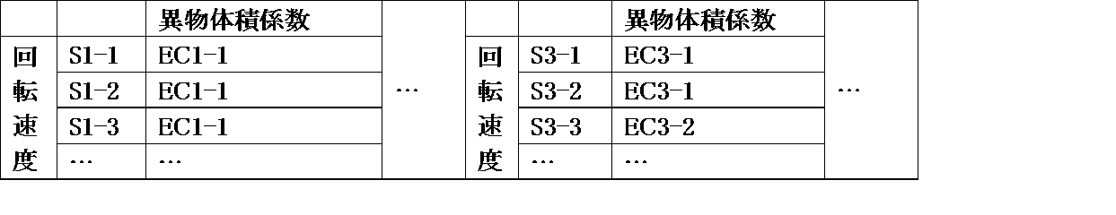
ECz3-z4(z3,z4=1,2,…):薬剤体積係数(z3は薬剤の形状の違いに依存する。)
なお、前記異物体積係数テーブルでは、異物体積係数を、薬剤の形状の違いに応じて紐づけするようにしたが、前記薬剤体積係数テーブルと同様に、第2回転体35の回転速度の違いに応じて紐づけするようにしてもよい。
次に、前記構成からなる薬剤計数装置の動作について説明する。
初期動作は、図14のフローチャートに示すように、薬剤を投入する前に、オペレータによって薬瓶に印刷された薬種ID(バーコード)がバーコードリーダ86で読み取られれば(ステップS1)、この薬種IDが処方データに示された薬剤と一致しているか否かを判断する(ステップS2)。一致していれば、正しい薬剤であると認定し、薬剤の投入を許可する(ステップS3)。これにより、誤った薬剤の払出を防止できる。次に、オペレータによって薬剤を受け入れる薬容器1のラベルに印刷された処方ID(バーコード)が読み取られれば(ステップS4)、この処方IDが処方データに示された処方IDと一致しているか否かを判断する(ステップS5)。一致していれば、薬剤の払出を許可する(ステップS6)。これにより、薬容器1の取り間違いを防止することができる。
薬剤排出処理では、図18に示すように、第1回転体23の角度調整処理を行い(ステップS11)、制御部83が薬剤に応じて各規制体41,52の自動調整(オートキャリブレーション)処理を実行すると共に(ステップS12)、実際に薬剤をカウントするカウント処理を実行する(ステップS13)。なお、薬剤排出処理は、自動調整処理中であっても実行することにより、自動調整処理中に薬剤検出ユニット70を通過する薬剤を計数し損ねることのないようにしている。
第1回転体23の角度調整処理は、投入する薬剤量及び薬剤の大きさや形状に応じて行う。すなわち、薬剤の量や形状の違いに応じて、薬剤が第1回転体23から第2回転体35へとスムーズに移動できるように調整する。具体的には、投入する薬剤量が多い場合、仕切壁18と第1回転体23と第2回転体35の間に形成される収容空間が広くなるように、第1回転体23の傾斜角度を急勾配(垂直に近く)とする。また、第1回転体23を回転させても上面で転動(自転)して第2回転体35へ移動しない球状の薬剤等の場合、第1回転体23の傾斜角度を緩勾配(水平に近く)とする。
自動調整処理では、新薬等の初めて計数する薬剤の場合、メモリ87にはその薬剤に関する体積データが記憶されていない。そこで、次のようにして薬剤の体積を測定する。また、薬剤検出ユニット70を通過する薬剤の間隔を測定し、第2回転体35の回転速度や、制御方法を決定し、その薬剤に関するデータ(ここでは、薬剤ID)に関連付けてメモリ87に記憶させる。
新薬等の初めて計数する薬剤の場合、及び、既に計数したことのある薬剤の場合、図20のフローチャートに示すように、まず、薬剤検出ユニット70での検出信号に基づいて、薬剤の体積(実測値)を算出する(ステップS51)。そして、この実測値と、メモリ87に記憶させてある薬剤演算値とを比較する(ステップS52)。その結果、実測値が薬剤演算値以上であれば(ステップS52:NO)、誤って2錠が排出されたと判断し、2を計数する(ステップS53)。
次に、薬剤供給装置によって薬剤の1つである円板状の錠剤Xの薬剤移送動作について具体的に説明する。なお、円板状錠剤Xの移送動作は、球状の薬剤であっても同様である。
次に、円板状錠剤Xとは形状や大きさが異なるカプセル剤Yの薬剤移送動作について具体的に説明する。なお、カプセル剤Yの移送動作は、楕円形状等の非円形状の錠剤であっても同様である。
残留薬剤検出処理は、初期動作の前に実行すればよい。以下、残留薬剤検出処理について、図25及び図26のフローチャートに従って説明する。
残留薬剤検出処理では、電源が投入されて薬剤計数装置が起動した場合等に、図38(a)に示すように、高さ規制体41及び幅規制体52を矢印a,b方向(但し、図中、矢印a方向は上向きとなっているが、実際には紙面に直交する手前方向。以下同じ。)に移動させ、最大開放位置に位置させる(ステップS111)。以下、最大開放位置は、高さ規制体41又は幅規制体52により形成される、第2回転体35上で薬剤が通過可能な高さ寸法又は幅寸法(第2回転体35の上方側の隙間又は第2回転体35上の径方向の隙間)が最も大きくなる位置を意味するものとして記載する。そして、高さ規制体41及び幅規制体52を最大開放位置に移動させた状態で、第2回転体35を最大速度で所定時間(ここでは、1.5秒間)矢印c´方向に逆回転させる(ステップS112)。これにより、第2回転体35上に残留する薬剤を排出方向とは逆方向に移動させることができる。
薬剤が検出されない場合(残薬無)、前記ステップS118~S123を続行し、ステップS123を終了すれば、高さ規制体41及び幅規制体52を、閉鎖位置に移動させた後(ステップS125)、第1制御部104に「残薬無」を送信する(ステップS126)。また、後述する図35に示すように、動作表示部107の払出表示LED107a及び回収表示LED107bを点灯させることにより(ステップS127)、残留薬剤検出処理を終了する。
すなわち、
第1の回転軸を中心として正回転することにより、薬剤を周方向及び外径方向に搬送可能な第1回転体と、
前記第1回転体の外周側に位置し、第2の回転軸を中心として正逆回転することにより、薬剤を周方向に搬送可能な第2回転体と、
前記第2回転体の外径側に配置され、搬送された薬剤を排出する払出部と、
前記払出部に対して前記第2回転体の回転方向上流側に配置され、前記第2回転体の上面との間隔を調整可能な高さ規制体と、
前記払出部と前記高さ規制体の間に配置され、前記第2回転体の内周縁との間隔を調整可能な幅規制体と、
カウント処理の前に、前記高さ規制体と前記幅規制体とを最大開放位置に移動させ、前記第2回転体を逆回転させ、幅規制体を閉鎖位置に移動させた後、正回転させる残留薬剤検出処理を実行する制御部と、
を備えたことを特徴とする薬剤供給装置。
第2制御部105では、前記自動調整処理の後、薬剤用カメラ106(前記実施形態に記載の第3カメラ89cに相当する。)によって薬剤の外観を撮像し、その画像を記憶させる撮像処理を実行することができるようになっている。
例えば、薬剤用カメラ106によって撮像可能な領域(撮像領域)を照明するための複数の照明部材(例えば、LED:図示せず)のいずれかにより照明するのかを決定することで行う。複数の照明部材は、外壁20のうち、高さ規制体41に対して第2回転体35の回転方向上流側の部分に、上下方向に並ぶように設けられている。撮影条件は、ユーザが自由に設定できるようにする。ここでは、モニタ88に、図43に示すような薬剤用カメラ106で撮像した画像121を含む画像調整画面を表示させ、その「light」ボタン122を操作することにより、「top」、「middle」、「bottom」、「off」のいずれかを選択できるように構成している(上位の照明部材で照明、中位の照明部材で照明、下位の照明部材で照明、照明せず、が選択される。)。これにより、薬剤の形状や、撮像領域での薬剤の向きや数等の違いに応じた撮像に最も適した状態で、薬剤を照明することができる。なお、照明部材は1つのみ設けられてもよい。1つの場合は、撮像条件の設定は、照明をするかしないかの選択によって行うことができる。
すなわち、
第1の回転軸を中心として正回転することにより、薬剤を周方向及び外径方向に搬送可能な第1回転体と、
前記第1回転体の外周側に位置し、第2の回転軸を中心として正回転することにより、薬剤を周方向に搬送可能な第2回転体と、
前記第2回転体の外径側に配置され、搬送された薬剤を排出する払出部と、
前記払出部に対して前記第2回転体の正回転方向上流側に配置され、前記薬剤の通過を規制する規制体と、
前記規制体の前記第2回転体の正回転方向上流側の撮像領域を撮像可能な撮像部と、
前記規制体により薬剤の移動を規制し、前記第2回転体を正回転させることにより、前記撮像領域に薬剤を位置させた状態で、前記撮像部による撮像領域の撮像を行わせる撮像処理を実行する制御部と、
を備えたことを特徴とする薬剤供給装置。
前記制御部は、前記設定した照射条件のいずれかを選択した状態で、前記撮像部による撮像を行わせるのが好ましい。
また、前記撮像処理は、法律により義務付けられている場合にのみ行い、それ以外では行わないようにすることも可能である。
前記カウント処理は、以下のような複数のモードを備えたものとすることができる。すなわち、図28及び図29のフローチャートに示すように、まず、いずれのモードによって薬剤を払い出し、かつ、計数するのかを判断する(ステップS151)。例えば、処方箋、薬容器1、又は、薬瓶のいずれかのバーコードがバーコードリーダで読み取られることにより、サーバに照会し、以下の(1)~(3)のいずれのモードに該当するのかを判断すればよい(具体的には、処方箋のバーコードが読み取られれば(1)、薬容器1のバーコードが読み取られれば(2)、薬瓶のバーコードが読み取られれば(3)のモードに移行させるようにすればよい。)。
(1)薬瓶から薬剤計数装置に供給された薬剤から、処方箋に従って予め決められた数量だけ、患者に渡す薬容器1に払い出すための通常払出カウントモード
(2)通常払出カウントモードで、他の薬剤計数装置で薬容器1に払い出した薬剤の数量を再度確認するための再カウントモード
(3)薬瓶から薬剤計数装置に供給された全ての薬剤を計数し、薬瓶に収容されている在庫量を確認するための在庫量カウントモード
すなわち、通常払出カウントモードでは、まず、動作表示部の払出表示LED107aを点滅させる(ステップS152)。そして、第1制御部104からの指示がある場合(ステップS153:YES)、図40(a)に示すように、第2回転体35を最大速度で所定時間(ここでは、0.3秒間)矢印c´方向に逆回転させる(ステップS154)。続いて、図40(b)に示すように、高さ規制体41及び幅規制体52を矢印a,b方向に移動させ、第1指定位置に位置させる(ステップS155)。ここで、第1指定位置とは、前記自動調整処理で決められた位置、すなわち、測定された薬剤のサイズに合わせた丁度該当する薬剤が通過可能な位置(高さ規制位置及び幅規制位置)を意味する。第1制御部104からの指示がない場合(ステップS153:NO)、ステップS154を実行することなく、直接、ステップS155を実行する。なお、前述の第1制御部104からの指示とは、例えば、前述の回収処理が行われた直後で、残留薬剤がないと判断される場合に、前記ステップS154で行った薬剤の詰まり解消処理をしない旨の指示を意味する。
すなわち、
回転軸を中心として正回転することにより、薬剤を周方向に搬送可能な回転体と、
前記回転体の外径側に配置される払出部と、
前記払出部から払い出される薬剤の数量を計数する計数部と、
処方データに基づいて、前記回転体を正回転させ、前記計数部での計数値が所定値に到達すれば、前記回転体の回転速度を低下させ、前記処方データの処方数量に到達すれば、前記回転体の正回転を停止する通常払出モードを実行する制御部と、
を備えたことを特徴とする薬剤供給装置。
前記制御部は、さらに、前記撮像部によって撮像された画像を、前記水剤を特定するための情報と共に前記記憶部に記憶させる水剤モードを実行するのが好ましい。
すなわち、カウントセンサの最大A/D値を検出し、この最大A/D値が汚れ検出レベルを超えているか否かを判断する。そして、最大A/D値が汚れ検出レベルを超えていれば、カウントセンサが汚れていると判断し、第1制御部104にワーニング通知する。カウントセンサの清掃後、解除処理(例えば、解除ボタンが操作される等)が実行され、第1制御部104から解除コマンドを受信すれば、再度、カウントセンサの最大A/D値を検出する。そして、この最大A/D値が、前記汚れ検出レベルよりも小さい値に設定した汚れ解除レベルを下回っているか否かを判断する。最大A/D値が汚れ解除レベルを下回っていなければ、再度ワーニング通知を行い、下回っていれば、ワーニング解除を実行する。汚れ検出レベルと汚れ解除レベルとに差を設けることにより、ワーニング通知とワーニング解除とが頻繁に切り替わることを防止することが可能となっている。
欠品判定処理は、図30のフローチャートに示すように、前記通常払出カウントモードや再カウントモードの途中で、薬剤検出ユニット70で薬剤を所定時間(ここでは、3秒間)検出できない場合(ステップS171)、薬剤検出ユニット70により薬剤が検出されなくなったのが2回以上であるのか否かを判断する(ステップS172)。
払出先である薬瓶(又は薬容器1、以下同じ)が払出位置から外された場合、次のようにして薬瓶外れ処理にて対応する。
払出位置には、図示しない薬瓶検出センサによって適切な位置に薬瓶が配置されているか否かが検出されている。そこで、薬瓶外れ処理では、図31のフローチャートに示すように、薬瓶検出センサ(図示せず)からの検出信号に基づいて、払出位置に薬瓶が配置されているか否かを判断する(ステップS181)。検出信号がオフであれば、払出位置から薬瓶が外れたと判断する。このとき、薬剤のカウント処理が完了しておらず、第1回転体23及び第2回転体35が回転中であれば、その正回転を強制的に停止する(ステップS182)。これにより、薬剤の漏出が防止される。
前記通常払出カウントモード、再カウントモード、あるいは、在庫量カウントモードが終了し、薬剤供給装置内に残留する薬剤を回収(排出)する場合、残留する薬剤に関する情報があれば第1回収処理を実行し、残留する薬剤に関する情報がなければ第2回収処理を実行する。
第1回収処理では、図32のフローチャートに示すように、第1制御部104からの逆回転指示があれば(ステップS191)、図41(a)に示すように、第2回転体35を所定時間(ここでは、0.3秒間)矢印c´方向に逆回転させる(ステップS192)。そして、図41(b)及び(c)に示すように、高さ規制体41及び幅規制体52を作動させて、矢印a,b方向に移動させ、第1制御部104からの指定位置に位置させる(ステップS193)。なお、高さ規制体41及び幅規制体52の移動位置は、残留する薬剤のサイズに応じたものである。
一方、薬剤検出ユニット70にて薬剤を所定時間内に検出できない場合(ステップS196:NO)、薬瓶が外れたか否かを判断する(ステップS197)。
薬瓶が外れていれば、第1回収処理を終了する。
第2回収処理でも、前記第1回収処理と同様に、図33のフローチャートに示すように、第1制御部104から逆回転指示があれば(ステップS211:YES)、図42(a)に示すように、第2回転体35を所定時間(ここでは、0.3秒間)矢印c´方向に逆回転させる(ステップS212)。そして、図42(b)及び(c)に示すように、高さ規制体41を矢印a方向に作動させて、最大開放位置へと移動させる(ステップS213)。また、幅規制体52を、矢印b方向に移動させ、予め設定した所定位置(ここでは、幅寸法が8mmとなる位置)に位置させる(ステップS214)。
薬瓶が外されれば、第2回収処理を終了する。
なお、カウントする薬剤の種類が変更される場合等、特に、粉が発生しやすい薬剤から変更される場合には、掃除モードを実行することができるようになっている。
薬剤が水剤である場合、例えば、処方箋に水剤が含まれている場合、後述するサイドカメラ108で、処方箋と、該当する水剤が収容された薬液ボトルとを一緒に撮像することができる。この場合、サイドカメラ108は、上方から手前に旋回させ、処方箋と薬液ボトルとを立てた状態で撮像する。これにより、薬液ボトル内の水剤の水位をも一緒に撮像し、処方箋の撮像データと共に記録しておくことが可能となる。
薬剤が箱詰めされた状態で提供される場合、箱に付与されたバーコードをバーコードリーダ89で読み取る。そして、読み取ったバーコードから該当する薬剤の写真データを呼び出し、画面表示させる。これにより、適切な薬剤であるのか否かを視覚により確認することができる。写真データ及び薬剤データ(名称等)は、第1制御部104に送信して記憶させるようにすればよい。なお、バーコードが付与されていないものについては、コード番号等を手入力すればよい。
図35に示す薬剤計数装置では、薬剤の払出位置が1箇所に集約されている。そして、その払出位置の両側には動作表示部107が設けられている。動作表示部107は、払出表示LED107aと回収表示LED107bとで構成されている。各LEDの表示パターンは次表の通りである。

また、傾斜部57a又は傾斜部66aを有する場合は、内側ガイド66と外側ガイド57との間隔は、幅が同じ回転楕円体の薬剤においても、長径と短径との比率によって異ならせる。これは、比率によって、薬剤と内側ガイド66、または、薬剤と外側ガイド57とが接触する位置が異なるためである。このため、幅補正係数は、上記比率に応じて決定してもよい。
すなわち、図44(a)に示すように、回転楕円体などの先端が細い形状の薬剤は、薬剤移送方向下流側の薬剤Z1の下側へ薬剤移送方向下流側の薬剤Z2が入りこみ、薬剤Z1の重心と薬剤Z2の重心の距離L2が、薬剤の寸法L1よりも短くなる場合がある。第2回転体35からの薬剤の排出は、薬剤の重心が第2回転体35上から外れると行われる。このため、薬剤が他の薬剤の下側に入り込み、重心間の距離が短くなる形状の薬剤では、薬剤の排出間隔が短くなる傾向がある。薬剤の排出間隔が短いと、検出部70が連続して排出された薬剤を1錠として認識するという問題が生じる。このような問題が生じる形状の薬剤については、第2回転体35の回転速度が遅くなるように、スピードテーブルに回転速度を設定し、薬剤の重心が第2回転体35上から外れる間隔を長くすることで、薬剤の排出間隔を長くし、検出部70が連続して排出された薬剤を1錠として認識するという問題の発生を防止できる。
2…回収容器
18…仕切壁
23…第1回転体
24…第1回転軸
28…第1駆動モータ
33…角度調整モータ
35…第2回転体
35a…リブ
36…内周部
37…移動部
39…第2駆動モータ
41…高さ規制体
49…高さ調整モータ
51…薬剤検出センサ(検出部)
52…幅規制体
57…外側ガイド
63…幅調整モータ
65…薬剤案内部
66…内側ガイド
68…傾斜縁
69…傾斜面
70…薬剤検出ユニット
71A~71D…発光部
72A~72D…受光部
73…薬剤払出部材(払出部)
74…シャッター
75…駆動モータ
76…切換弁ユニット
77…薬剤通路
78…払出部
79…回収部
80A,80B…揺動部材
81…弾性部
82A,82B…駆動モータ
83…制御部(制御部)
85…操作パネル(薬剤形状特定部)
86…バーコードリーダ
87…メモリ(記憶部)
88…モニタ
89…バーコードリーダ
101…第1センサ
102…第2センサ
103…第3センサ
104…第1制御部
105…第2制御部
106…薬剤用カメラ
107…動作表示部
107a…払出表示LED
107b…回収表示LED
108…サイドカメラ
109…アーム
110…鏡
111…スケール
X,X1…錠剤(薬剤)
Y,Y1,Y2…カプセル剤(薬剤)
Claims (16)
- 回転することにより、薬剤を外径側に排出する回転体と、
前記薬剤の形状を特定するための薬剤形状特定部と、
前記薬剤の形状と前記回転体の回転速度とを紐づけるスピードテーブルに基づいて、前記薬剤形状特定部によって特定された形状から特定される回転速度で前記回転体を回転させる制御部と、
を備えたことを特徴とする薬剤供給装置。 - 回転することにより、薬剤を外径側に排出する回転体と、
前記回転体から薬剤が排出される間隔を検出する検出部と、
前記検出部によって検出される薬剤の間隔と、該薬剤の間隔を所望の値にするための前記回転体の回転速度とを紐づけたスピードテーブルに基づいて、前記検出部によって検出される薬剤の間隔から特定される回転速度で前記回転体を回転させる制御部と、
を備えたことを特徴とする薬剤供給装置。 - 回転することにより、薬剤を外径側に排出する回転体と、
前記回転体から排出される薬剤を検出する検出部と、
前記薬剤の形状を特定するための薬剤形状特定部と、
前記薬剤の形状と前記回転体の回転速度とを紐づけるスピードテーブルに基づいて、前記薬剤形状特定部によって特定された形状から特定される回転速度で前記回転体を回転させ、前記検出部によって検出される薬剤の排出数が処方データに含まれる薬剤の処方数に到達することにより、前記回転体を停止させる制御部と、
を備えたことを特徴とする薬剤計数装置。 - 回転することにより、薬剤を外径側に排出する回転体と、
前記回転体から排出される薬剤を検出する検出部と、
前記検出部によって検出される薬剤の間隔と前記回転体の回転速度とを紐づけるスピードテーブルに基づいて、前記検出部によって検出された薬剤の間隔から特定される回転速度で前記回転体を回転させ、前記検出部によって検出される薬剤の排出数が処方データに含まれる薬剤の処方数に到達することにより、前記回転体を停止させる制御部と、
を備えたことを特徴とする薬剤計数装置。 - 前記薬剤形状特定部は、薬剤の平面形状と側面形状を選択することにより薬剤の形状を特定するものであることを特徴とする請求項3に記載の薬剤計数装置。
- 前記薬剤の基準体積を特定する薬剤体積特定部を、さらに備え、
前記制御部は、前記薬剤の形状と、薬剤体積係数とを紐づける薬剤体積係数テーブルに基づいて、前記薬剤形状特定部によって特定された形状から特定される薬剤体積係数と、前記薬剤体積特定部によって特定された基準体積との積が、前記検出部からの検出信号に基づいて算出した薬剤の体積以上であれば薬剤の排出数が1であるとして計数することを特徴とする請求項3又は5に記載の薬剤計数装置。 - 前記薬剤の基準体積を特定する薬剤体積特定部を、さらに備え、
前記制御部は、前記回転体の回転速度と、薬剤体積係数とを紐づける薬剤体積係数テーブルに基づいて、前記スピードテーブルにより決定した回転速度から特定される薬剤体積係数と、前記薬剤体積特定部によって特定された基準体積との積が、前記検出部からの検出信号に基づいて算出した薬剤の体積を超えていれば薬剤の排出数が1であるとして計数することを特徴とする請求項3又は5に記載の薬剤計数装置。 - 前記薬剤の基準体積を特定する薬剤体積特定部を、さらに備え、
前記制御部は、前記薬剤の形状と、異物体積係数とを紐づける異物体積係数テーブルに基づいて、前記薬剤形状特定部によって特定された形状から特定される異物体積係数と、前記薬剤体積特定部によって特定された基準体積との積が、前記検出部からの検出信号に基づいて算出した薬剤の体積を超えていれば計数しないことを特徴とする請求項3又は5に記載の薬剤計数装置。 - 前記薬剤の基準体積を特定する薬剤体積特定部を、さらに備え、
前記制御部は、前記回転体の回転速度と、異物体積係数とを紐づける異物体積係数テーブルに基づいて、前記スピードテーブルにより決定した回転速度から特定される異物体積係数と、前記薬剤体積特定部によって特定された基準体積との積が、前記検出部からの検出信号に基づいて算出した薬剤の体積を超えていれば計数しないことを特徴とする請求項3又は5に記載の薬剤計数装置。 - 前記制御部は、前記薬剤の形状と、前記回転体の回転速度が低下し始める薬剤の排出残数とを紐づけるスローダウンテーブルに基づいて、前記薬剤形状特定部によって特定された形状から特定される排出残数に、処方データに含まれる薬剤の処方数から薬剤の排出数を引いた数が到達すれば、前記回転体の回転速度を低下させることを特徴とする請求項3から9のいずれか1項に記載の薬剤計数装置。
- 前記排出残数は、前記薬剤の形状に応じて相違させることを特徴とする請求項10に記載の薬剤計数装置。
- 前記排出残数は、前記回転体の回転速度に応じて相違させることを特徴とする請求項10に記載の薬剤計数装置。
- 前記制御部は、前記回転体の回転速度の低下を多段階で行わせることを特徴とする請求項10から12のいずれか1項に記載の薬剤計数装置。
- 前記制御部は、前記検出部によって検出される薬剤の排出数が処方データに含まれる薬剤の処方数に到達することにより前記回転体を逆回転させることを特徴とする請求項3から13のいずれか1項に記載の薬剤計数装置。
- 前記回転体の上方に、上下方向に移動可能に設けられた高さ規制部材と、
前記薬剤の基準高さを特定するための薬剤高さ特定部と、
をさらに備え、
前記制御部は、前記薬剤の形状と、高さ補正係数とを紐づける高さ補正テーブルに基づいて、前記薬剤形状特定部によって特定された形状から特定される高さ補正係数と、前記薬剤高さ特定部によって特定される基準高さとに基づいて、前記高さ規制部材の位置を調整することを特徴とする請求項3から14のいずれか1項に記載の薬剤計数装置。 - 前記回転体の上面に、前記回転体の径方向に移動可能に設けられた幅規制部材と、
前記薬剤の基準幅を特定するための薬剤幅特定部と、
をさらに備え、
前記制御部は、前記薬剤の形状と、幅補正計数とを紐づける幅補正テーブルに基づいて、前記薬剤形状特定部によって特定された形状から特定される幅補正係数と、前記薬剤幅特定部によって特定される基準幅とに基づいて、前記幅規制部材の位置を調整することを特徴とする請求項3から15のいずれか1項に記載の薬剤計数装置。
Priority Applications (7)
| Application Number | Priority Date | Filing Date | Title |
|---|---|---|---|
| JP2014506175A JP6213459B2 (ja) | 2012-03-21 | 2013-03-14 | 薬剤供給装置及び薬剤計数装置 |
| US14/386,774 US9233789B2 (en) | 2012-03-21 | 2013-03-14 | Medicine-supplying device and medicine-counting device |
| CN201380015849.XA CN104245515B (zh) | 2012-03-21 | 2013-03-14 | 药剂供给装置及药剂计数装置 |
| EP13763592.6A EP2829480B1 (en) | 2012-03-21 | 2013-03-14 | Drug-supplying device and drug-counting device |
| KR1020147026237A KR20140138187A (ko) | 2012-03-21 | 2013-03-14 | 약제 공급 장치 및 약제 계수 장치 |
| US14/954,864 US9611084B2 (en) | 2012-03-21 | 2015-11-30 | Medicine-supplying device and medicine-counting device |
| US15/438,543 US9962317B2 (en) | 2012-03-21 | 2017-02-21 | Medicine-supplying device and medicine-counting device |
Applications Claiming Priority (4)
| Application Number | Priority Date | Filing Date | Title |
|---|---|---|---|
| JP2012-064100 | 2012-03-21 | ||
| JP2012064100 | 2012-03-21 | ||
| JP2012-211369 | 2012-09-25 | ||
| JP2012211369 | 2012-09-25 |
Related Child Applications (2)
| Application Number | Title | Priority Date | Filing Date |
|---|---|---|---|
| US14/386,774 A-371-Of-International US9233789B2 (en) | 2012-03-21 | 2013-03-14 | Medicine-supplying device and medicine-counting device |
| US14/954,864 Continuation US9611084B2 (en) | 2012-03-21 | 2015-11-30 | Medicine-supplying device and medicine-counting device |
Publications (1)
| Publication Number | Publication Date |
|---|---|
| WO2013141130A1 true WO2013141130A1 (ja) | 2013-09-26 |
Family
ID=49222589
Family Applications (1)
| Application Number | Title | Priority Date | Filing Date |
|---|---|---|---|
| PCT/JP2013/057154 WO2013141130A1 (ja) | 2012-03-21 | 2013-03-14 | 薬剤供給装置及び薬剤計数装置 |
Country Status (7)
| Country | Link |
|---|---|
| US (3) | US9233789B2 (ja) |
| EP (1) | EP2829480B1 (ja) |
| JP (1) | JP6213459B2 (ja) |
| KR (1) | KR20140138187A (ja) |
| CN (1) | CN104245515B (ja) |
| TW (1) | TWI605991B (ja) |
| WO (1) | WO2013141130A1 (ja) |
Cited By (13)
| Publication number | Priority date | Publication date | Assignee | Title |
|---|---|---|---|---|
| CN104648728A (zh) * | 2013-11-20 | 2015-05-27 | 克朗斯股份公司 | 用于薄膜软管的导向装置以及用于导向装置的控制装置 |
| WO2015119055A1 (ja) * | 2014-02-06 | 2015-08-13 | 株式会社湯山製作所 | 薬品撮影装置、薬品形状測定装置、薬品払出装置 |
| JP2016007512A (ja) * | 2014-06-26 | 2016-01-18 | 株式会社湯山製作所 | 薬剤払い出し情報印刷システムおよび薬剤払い出し装置 |
| CN105270688A (zh) * | 2015-03-06 | 2016-01-27 | 南通恒力医药设备有限公司 | 一种基于视觉监测的电子数粒机 |
| CN107161429A (zh) * | 2017-05-27 | 2017-09-15 | 肇庆市端州区图恩斯科技有限公司 | 晶振自动包装机 |
| CN108891894A (zh) * | 2018-08-27 | 2018-11-27 | 镇江仕德汽车零部件有限公司 | 一种上料装置用自动调节机构 |
| EP3384891A4 (en) * | 2015-11-30 | 2019-06-12 | Yuyama Mfg. Co., Ltd. | MEDICAMENT CARTET, DRUG DELIVERY AND MEDICAMENT PACKAGING DEVICE |
| JP2019180969A (ja) * | 2018-04-13 | 2019-10-24 | 株式会社タカゾノ | 薬剤供給装置 |
| JP2019180970A (ja) * | 2018-04-13 | 2019-10-24 | 株式会社タカゾノ | 薬剤供給装置 |
| WO2020162021A1 (ja) * | 2019-02-04 | 2020-08-13 | 株式会社タカゾノ | 薬剤供給装置 |
| CN113071903A (zh) * | 2021-03-31 | 2021-07-06 | 锎量(宁夏)自动化科技有限公司 | 一种摆药机漏药药盒 |
| JP7389395B2 (ja) | 2018-08-09 | 2023-11-30 | 株式会社湯山製作所 | 薬剤払出装置 |
| US11925604B2 (en) | 2021-06-22 | 2024-03-12 | Vmi Holland B.V. | Method, computer program product and dispensing device for dispensing discrete medicaments |
Families Citing this family (28)
| Publication number | Priority date | Publication date | Assignee | Title |
|---|---|---|---|---|
| JP6109421B2 (ja) * | 2013-08-09 | 2017-04-05 | パーセプティメッド インコーポレイテッドPerceptimed, Inc. | ピルフィーダ |
| US9940439B2 (en) * | 2013-11-29 | 2018-04-10 | Atabak Reza Royaee | Method and device for identification and/or sorting of medicines |
| WO2016013553A1 (ja) * | 2014-07-23 | 2016-01-28 | 株式会社湯山製作所 | 薬剤カセット |
| KR20160072725A (ko) * | 2014-12-15 | 2016-06-23 | (주)크레템 | 약제포장유닛 및 이의 약제 이송 방법 |
| CA2977946C (en) | 2015-02-26 | 2021-08-31 | Suhjun Park | Dispensing device, valve, containing apparatus having same, contents moving apparatus and contents apparatus |
| CA2982433C (en) * | 2015-04-11 | 2023-06-20 | Yuyama Mfg. Co., Ltd. | Medicine dispensing cassette |
| CN105109722A (zh) * | 2015-08-27 | 2015-12-02 | 苏州捷碧医疗科技有限公司 | 一种全自动分药和供药系统及固体药物自动分离方法 |
| KR101874328B1 (ko) | 2016-02-01 | 2018-07-05 | 박서준 | 통과 장치, 밸브, 이를 구비하는 수용 기구, 내용물 이동 기구 및 내용물 기구 |
| WO2017135654A1 (ko) * | 2016-02-01 | 2017-08-10 | 박서준 | 통과 장치, 밸브, 이를 구비하는 수용 기구, 내용물 이동 기구 및 내용물 기구 |
| CN109195567B (zh) * | 2016-08-05 | 2021-04-06 | 株式会社汤山制作所 | 药剂分包装置 |
| CN107757984B (zh) * | 2016-08-17 | 2020-04-17 | 诸暨市银生珍珠养殖有限公司 | 一种珍珠包装流水线定量送料装置 |
| JPWO2018092771A1 (ja) * | 2016-11-15 | 2019-10-17 | 株式会社湯山製作所 | 薬剤包装装置 |
| US10526131B2 (en) * | 2017-06-21 | 2020-01-07 | Toly Management Ltd. | Sweep bead dispenser |
| US10839635B2 (en) | 2017-06-21 | 2020-11-17 | Toly Management Ltd. | Sweep bead dispenser |
| KR20200105810A (ko) * | 2017-10-13 | 2020-09-09 | 알엑스세이프 엘엘씨 | 자동 포장기를 위한 범용 급송 메커니즘 |
| AU2019396903A1 (en) * | 2018-12-13 | 2021-05-20 | Yuyama Mfg. Co., Ltd. | Tablet cassette rotor and tablet cassette |
| CN109602611A (zh) * | 2019-01-17 | 2019-04-12 | 台光五金制品(东莞)有限公司 | 一种用于固态药品的分药机 |
| CN111688956A (zh) * | 2019-03-14 | 2020-09-22 | 梅特勒-托利多(常州)测量技术有限公司 | 可连续称重计数及包装的方法 |
| EP3948364A4 (en) | 2019-04-05 | 2023-04-12 | Blue Sky Ventures (Ontario) Inc. | SENSOR ASSEMBLY FOR MOVING ARTICLES AND ASSOCIATED FILLING MACHINE AND METHODS |
| CN110147868B (zh) * | 2019-05-22 | 2023-07-11 | 河南省计量科学研究院 | 一种用于定量包装商品净含量检验装置 |
| WO2021153674A1 (ja) * | 2020-01-29 | 2021-08-05 | 株式会社トーショー | 薬剤フィーダ |
| EP3925590A1 (de) * | 2020-06-16 | 2021-12-22 | Becton Dickinson Rowa Germany GmbH | Vorratsbehälter für eine vorrats- und abgabestation |
| US11352194B2 (en) | 2020-06-16 | 2022-06-07 | Becton Dickinson Rowa Germany Gmbh | Storage container for a storage and dispensing station |
| US20220332493A1 (en) * | 2021-04-16 | 2022-10-20 | Hero Health Inc. | Vacuum-based retrieving and dispensing |
| CN113142905B (zh) * | 2021-04-26 | 2022-07-22 | 佳木斯大学 | 一种药剂发药装置及操作方法 |
| CN113605876B (zh) * | 2021-08-11 | 2023-07-18 | 沧州格锐特钻头有限公司 | 一种牙轮钻头状态检测方法 |
| IT202100031082A1 (it) * | 2021-12-10 | 2023-06-10 | Antares Vision S P A | Carrello per la distribuzione di medicinali |
| CN114455148B (zh) * | 2022-01-27 | 2023-07-14 | 西门子(中国)有限公司 | 理片堆垛机的控制方法及理片堆垛机 |
Citations (6)
| Publication number | Priority date | Publication date | Assignee | Title |
|---|---|---|---|---|
| JPS5723516A (en) * | 1980-07-11 | 1982-02-06 | F I T:Kk | Accommodated shape parts supplying device |
| JPH0151403B2 (ja) | 1981-06-25 | 1989-11-02 | Fit Kk | |
| US5369940A (en) * | 1993-01-27 | 1994-12-06 | Pfizer Inc | Automatic filling system |
| US20040118753A1 (en) * | 2002-12-09 | 2004-06-24 | Ray Belway | Universal pill counting device |
| US20060225383A1 (en) * | 2005-04-08 | 2006-10-12 | Jm Smith Corporation | Pharmaceutical singulation counting and dispensing system |
| WO2012099189A1 (ja) * | 2011-01-20 | 2012-07-26 | 株式会社湯山製作所 | 薬剤供給装置および薬剤供給装置を用いた薬剤計数装置 |
Family Cites Families (19)
| Publication number | Priority date | Publication date | Assignee | Title |
|---|---|---|---|---|
| US5884408A (en) | 1995-04-19 | 1999-03-23 | Simmons; Glenn | Graduated measuring device with color coded indicia |
| US5884806A (en) * | 1996-12-02 | 1999-03-23 | Innovation Associates, Inc. | Device that counts and dispenses pills |
| JP3673484B2 (ja) * | 2001-05-16 | 2005-07-20 | 株式会社エフアイテイ | 回転式整列供給機 |
| CN2512521Y (zh) * | 2001-10-18 | 2002-09-25 | 广得利胶囊股份有限公司 | 圆盘式的胶囊/锭剂自动筛选机 |
| US6997341B2 (en) | 2001-12-14 | 2006-02-14 | Pearson Research & Development, L.L.C. | Vacuum drum pill counter |
| US20060213921A1 (en) * | 2005-03-23 | 2006-09-28 | Gazi Abdulhay | Pill dispensing apparatus |
| CA2533265C (en) * | 2005-01-27 | 2013-07-30 | Sanyo Electric Co., Ltd. | Medicine supply apparatus and tablet case |
| US20080179387A1 (en) * | 2005-02-08 | 2008-07-31 | Ian James Cantlay | Medication Dispensing System |
| US7689318B2 (en) * | 2005-08-19 | 2010-03-30 | Lonnie Draper | Inventory control and prescription dispensing system |
| US7765776B1 (en) * | 2006-10-19 | 2010-08-03 | Medco Health Solutions, Inc. | Systems and methods for dispensing pharmaceutical/medical product and branding pharmaceutical/medical containers |
| CA2683186C (en) * | 2007-05-18 | 2013-07-09 | Parata Systems, Llc | Methods and apparatus for dispensing solid pharmaceutical articles |
| JP5346023B2 (ja) * | 2007-09-21 | 2013-11-20 | クレテム カンパニー,リミテッド | 薬剤包装装置の自由形状錠剤の自動排出器及び錠剤供給方法 |
| JP5154522B2 (ja) * | 2008-09-04 | 2013-02-27 | 株式会社シンキー | 材料充填装置及び材料充填方法 |
| KR101800029B1 (ko) * | 2009-04-17 | 2017-11-21 | 가부시키가이샤 유야마 세이사쿠쇼 | 약제 피더 및 약제 불출 장치 |
| US8281553B2 (en) * | 2009-05-29 | 2012-10-09 | Jvm Co., Ltd. | Automated medicine storage and medicine introduction/discharge management system |
| US9333541B2 (en) * | 2010-03-01 | 2016-05-10 | Yuyama Mfg. Co., Ltd. | Powder removal device of medicine dispenser |
| GB2486939B (en) * | 2011-12-01 | 2012-11-21 | Data Detection Technologies Ltd | Method and apparatus for dispensing items |
| KR102385169B1 (ko) * | 2013-01-18 | 2022-04-11 | 가부시키가이샤 유야마 세이사쿠쇼 | 약품 불출 장치, 약품 불출 방법, 약품 불출 프로그램, 기록 매체 |
| JP5950876B2 (ja) * | 2013-07-25 | 2016-07-13 | 株式会社トーショー | 薬剤フィーダ |
-
2013
- 2013-03-14 EP EP13763592.6A patent/EP2829480B1/en active Active
- 2013-03-14 US US14/386,774 patent/US9233789B2/en active Active
- 2013-03-14 WO PCT/JP2013/057154 patent/WO2013141130A1/ja active Application Filing
- 2013-03-14 JP JP2014506175A patent/JP6213459B2/ja active Active
- 2013-03-14 CN CN201380015849.XA patent/CN104245515B/zh active Active
- 2013-03-14 KR KR1020147026237A patent/KR20140138187A/ko not_active Application Discontinuation
- 2013-03-21 TW TW102110113A patent/TWI605991B/zh active
-
2015
- 2015-11-30 US US14/954,864 patent/US9611084B2/en active Active
-
2017
- 2017-02-21 US US15/438,543 patent/US9962317B2/en active Active
Patent Citations (6)
| Publication number | Priority date | Publication date | Assignee | Title |
|---|---|---|---|---|
| JPS5723516A (en) * | 1980-07-11 | 1982-02-06 | F I T:Kk | Accommodated shape parts supplying device |
| JPH0151403B2 (ja) | 1981-06-25 | 1989-11-02 | Fit Kk | |
| US5369940A (en) * | 1993-01-27 | 1994-12-06 | Pfizer Inc | Automatic filling system |
| US20040118753A1 (en) * | 2002-12-09 | 2004-06-24 | Ray Belway | Universal pill counting device |
| US20060225383A1 (en) * | 2005-04-08 | 2006-10-12 | Jm Smith Corporation | Pharmaceutical singulation counting and dispensing system |
| WO2012099189A1 (ja) * | 2011-01-20 | 2012-07-26 | 株式会社湯山製作所 | 薬剤供給装置および薬剤供給装置を用いた薬剤計数装置 |
Cited By (26)
| Publication number | Priority date | Publication date | Assignee | Title |
|---|---|---|---|---|
| CN104648728B (zh) * | 2013-11-20 | 2017-05-10 | 克朗斯股份公司 | 用于薄膜软管的导向装置以及用于导向装置的控制装置 |
| CN104648728A (zh) * | 2013-11-20 | 2015-05-27 | 克朗斯股份公司 | 用于薄膜软管的导向装置以及用于导向装置的控制装置 |
| US10192322B2 (en) | 2014-02-06 | 2019-01-29 | Yuyama Mfg. Co., Ltd. | Medicine photographing apparatus, medicine shape measuring apparatus and medicine dispensing apparatus |
| JP5812228B1 (ja) * | 2014-02-06 | 2015-11-11 | 株式会社湯山製作所 | 薬品撮影装置、薬品形状測定装置、薬品払出装置 |
| WO2015119055A1 (ja) * | 2014-02-06 | 2015-08-13 | 株式会社湯山製作所 | 薬品撮影装置、薬品形状測定装置、薬品払出装置 |
| JP2019000675A (ja) * | 2014-02-06 | 2019-01-10 | 株式会社湯山製作所 | 薬品払出装置、調整方法 |
| JP2016007512A (ja) * | 2014-06-26 | 2016-01-18 | 株式会社湯山製作所 | 薬剤払い出し情報印刷システムおよび薬剤払い出し装置 |
| CN105270688A (zh) * | 2015-03-06 | 2016-01-27 | 南通恒力医药设备有限公司 | 一种基于视觉监测的电子数粒机 |
| CN105270688B (zh) * | 2015-03-06 | 2019-01-29 | 南通恒力包装科技股份有限公司 | 一种基于视觉监测的电子数粒机 |
| US11406567B2 (en) | 2015-11-30 | 2022-08-09 | Yuyama Mfg. Co., Ltd. | Medicine cassette, medicine dispensing apparatus and medicine packaging apparatus |
| US10894003B2 (en) | 2015-11-30 | 2021-01-19 | Yuyama Mfg. Co., Ltd. | Medicine cassette, medicine dispensing apparatus and medicine packaging apparatus |
| EP3384891A4 (en) * | 2015-11-30 | 2019-06-12 | Yuyama Mfg. Co., Ltd. | MEDICAMENT CARTET, DRUG DELIVERY AND MEDICAMENT PACKAGING DEVICE |
| US10391036B2 (en) | 2015-11-30 | 2019-08-27 | Yuyama Mfg. Co., Ltd. | Medicine cassette, medicine dispensing apparatus and medicine packaging apparatus |
| CN107161429A (zh) * | 2017-05-27 | 2017-09-15 | 肇庆市端州区图恩斯科技有限公司 | 晶振自动包装机 |
| JP2019180970A (ja) * | 2018-04-13 | 2019-10-24 | 株式会社タカゾノ | 薬剤供給装置 |
| JP2019180969A (ja) * | 2018-04-13 | 2019-10-24 | 株式会社タカゾノ | 薬剤供給装置 |
| JP7029165B2 (ja) | 2018-04-13 | 2022-03-03 | 株式会社タカゾノ | 薬剤供給装置 |
| JP7029166B2 (ja) | 2018-04-13 | 2022-03-03 | 株式会社タカゾノ | 薬剤供給装置 |
| JP7389395B2 (ja) | 2018-08-09 | 2023-11-30 | 株式会社湯山製作所 | 薬剤払出装置 |
| CN108891894A (zh) * | 2018-08-27 | 2018-11-27 | 镇江仕德汽车零部件有限公司 | 一种上料装置用自动调节机构 |
| WO2020162021A1 (ja) * | 2019-02-04 | 2020-08-13 | 株式会社タカゾノ | 薬剤供給装置 |
| JP2020124328A (ja) * | 2019-02-04 | 2020-08-20 | 株式会社タカゾノ | 薬剤供給装置 |
| JP7357327B2 (ja) | 2019-02-04 | 2023-10-06 | 株式会社タカゾノ | 薬剤供給装置 |
| CN113071903A (zh) * | 2021-03-31 | 2021-07-06 | 锎量(宁夏)自动化科技有限公司 | 一种摆药机漏药药盒 |
| US11925604B2 (en) | 2021-06-22 | 2024-03-12 | Vmi Holland B.V. | Method, computer program product and dispensing device for dispensing discrete medicaments |
| US11931317B2 (en) | 2021-06-22 | 2024-03-19 | Vmi Holland B.V. | Method, computer program product and dispensing device for dispensing discrete medicaments |
Also Published As
| Publication number | Publication date |
|---|---|
| EP2829480B1 (en) | 2021-02-24 |
| EP2829480A1 (en) | 2015-01-28 |
| TW201343498A (zh) | 2013-11-01 |
| US9962317B2 (en) | 2018-05-08 |
| US9611084B2 (en) | 2017-04-04 |
| US9233789B2 (en) | 2016-01-12 |
| TWI605991B (zh) | 2017-11-21 |
| US20160185507A1 (en) | 2016-06-30 |
| JP6213459B2 (ja) | 2017-10-18 |
| CN104245515B (zh) | 2017-04-05 |
| KR20140138187A (ko) | 2014-12-03 |
| CN104245515A (zh) | 2014-12-24 |
| US20150129603A1 (en) | 2015-05-14 |
| JPWO2013141130A1 (ja) | 2015-08-03 |
| US20170224587A1 (en) | 2017-08-10 |
| EP2829480A4 (en) | 2016-03-30 |
Similar Documents
| Publication | Publication Date | Title |
|---|---|---|
| JP6213459B2 (ja) | 薬剤供給装置及び薬剤計数装置 | |
| JP7381977B2 (ja) | 薬剤供給装置 | |
| CA2922451C (en) | Object dispenser having a variable orifice and image identification | |
| JP6874870B2 (ja) | 薬剤鑑査支援装置 | |
| CN109152700B (zh) | 药剂分发装置 | |
| JP6274319B2 (ja) | 薬剤分包装置 |
Legal Events
| Date | Code | Title | Description |
|---|---|---|---|
| 121 | Ep: the epo has been informed by wipo that ep was designated in this application |
Ref document number: 13763592 Country of ref document: EP Kind code of ref document: A1 |
|
| ENP | Entry into the national phase |
Ref document number: 2014506175 Country of ref document: JP Kind code of ref document: A |
|
| WWE | Wipo information: entry into national phase |
Ref document number: 2013763592 Country of ref document: EP |
|
| ENP | Entry into the national phase |
Ref document number: 20147026237 Country of ref document: KR Kind code of ref document: A |
|
| WWE | Wipo information: entry into national phase |
Ref document number: 14386774 Country of ref document: US |
|
| NENP | Non-entry into the national phase |
Ref country code: DE |