WO2013118782A1 - 車輪用軸受装置 - Google Patents
車輪用軸受装置 Download PDFInfo
- Publication number
- WO2013118782A1 WO2013118782A1 PCT/JP2013/052767 JP2013052767W WO2013118782A1 WO 2013118782 A1 WO2013118782 A1 WO 2013118782A1 JP 2013052767 W JP2013052767 W JP 2013052767W WO 2013118782 A1 WO2013118782 A1 WO 2013118782A1
- Authority
- WO
- WIPO (PCT)
- Prior art keywords
- grease
- seal
- wheel bearing
- wheel
- bearing device
- Prior art date
Links
Images


Classifications
-
- B—PERFORMING OPERATIONS; TRANSPORTING
- B60—VEHICLES IN GENERAL
- B60B—VEHICLE WHEELS; CASTORS; AXLES FOR WHEELS OR CASTORS; INCREASING WHEEL ADHESION
- B60B27/00—Hubs
- B60B27/0073—Hubs characterised by sealing means
-
- B—PERFORMING OPERATIONS; TRANSPORTING
- B60—VEHICLES IN GENERAL
- B60B—VEHICLE WHEELS; CASTORS; AXLES FOR WHEELS OR CASTORS; INCREASING WHEEL ADHESION
- B60B27/00—Hubs
- B60B27/0005—Hubs with ball bearings
-
- F—MECHANICAL ENGINEERING; LIGHTING; HEATING; WEAPONS; BLASTING
- F16—ENGINEERING ELEMENTS AND UNITS; GENERAL MEASURES FOR PRODUCING AND MAINTAINING EFFECTIVE FUNCTIONING OF MACHINES OR INSTALLATIONS; THERMAL INSULATION IN GENERAL
- F16C—SHAFTS; FLEXIBLE SHAFTS; ELEMENTS OR CRANKSHAFT MECHANISMS; ROTARY BODIES OTHER THAN GEARING ELEMENTS; BEARINGS
- F16C33/00—Parts of bearings; Special methods for making bearings or parts thereof
- F16C33/30—Parts of ball or roller bearings
- F16C33/66—Special parts or details in view of lubrication
- F16C33/6603—Special parts or details in view of lubrication with grease as lubricant
- F16C33/6633—Grease properties or compositions, e.g. rheological properties
-
- F—MECHANICAL ENGINEERING; LIGHTING; HEATING; WEAPONS; BLASTING
- F16—ENGINEERING ELEMENTS AND UNITS; GENERAL MEASURES FOR PRODUCING AND MAINTAINING EFFECTIVE FUNCTIONING OF MACHINES OR INSTALLATIONS; THERMAL INSULATION IN GENERAL
- F16C—SHAFTS; FLEXIBLE SHAFTS; ELEMENTS OR CRANKSHAFT MECHANISMS; ROTARY BODIES OTHER THAN GEARING ELEMENTS; BEARINGS
- F16C33/00—Parts of bearings; Special methods for making bearings or parts thereof
- F16C33/72—Sealings
- F16C33/76—Sealings of ball or roller bearings
- F16C33/78—Sealings of ball or roller bearings with a diaphragm, disc, or ring, with or without resilient members
- F16C33/7816—Details of the sealing or parts thereof, e.g. geometry, material
- F16C33/782—Details of the sealing or parts thereof, e.g. geometry, material of the sealing region
- F16C33/7826—Details of the sealing or parts thereof, e.g. geometry, material of the sealing region of the opposing surface cooperating with the seal, e.g. a shoulder surface of a bearing ring
-
- F—MECHANICAL ENGINEERING; LIGHTING; HEATING; WEAPONS; BLASTING
- F16—ENGINEERING ELEMENTS AND UNITS; GENERAL MEASURES FOR PRODUCING AND MAINTAINING EFFECTIVE FUNCTIONING OF MACHINES OR INSTALLATIONS; THERMAL INSULATION IN GENERAL
- F16C—SHAFTS; FLEXIBLE SHAFTS; ELEMENTS OR CRANKSHAFT MECHANISMS; ROTARY BODIES OTHER THAN GEARING ELEMENTS; BEARINGS
- F16C33/00—Parts of bearings; Special methods for making bearings or parts thereof
- F16C33/72—Sealings
- F16C33/76—Sealings of ball or roller bearings
- F16C33/78—Sealings of ball or roller bearings with a diaphragm, disc, or ring, with or without resilient members
- F16C33/7869—Sealings of ball or roller bearings with a diaphragm, disc, or ring, with or without resilient members mounted with a cylindrical portion to the inner surface of the outer race and having a radial portion extending inward
- F16C33/7873—Sealings of ball or roller bearings with a diaphragm, disc, or ring, with or without resilient members mounted with a cylindrical portion to the inner surface of the outer race and having a radial portion extending inward with a single sealing ring of generally L-shaped cross-section
-
- F—MECHANICAL ENGINEERING; LIGHTING; HEATING; WEAPONS; BLASTING
- F16—ENGINEERING ELEMENTS AND UNITS; GENERAL MEASURES FOR PRODUCING AND MAINTAINING EFFECTIVE FUNCTIONING OF MACHINES OR INSTALLATIONS; THERMAL INSULATION IN GENERAL
- F16C—SHAFTS; FLEXIBLE SHAFTS; ELEMENTS OR CRANKSHAFT MECHANISMS; ROTARY BODIES OTHER THAN GEARING ELEMENTS; BEARINGS
- F16C33/00—Parts of bearings; Special methods for making bearings or parts thereof
- F16C33/72—Sealings
- F16C33/76—Sealings of ball or roller bearings
- F16C33/78—Sealings of ball or roller bearings with a diaphragm, disc, or ring, with or without resilient members
- F16C33/7869—Sealings of ball or roller bearings with a diaphragm, disc, or ring, with or without resilient members mounted with a cylindrical portion to the inner surface of the outer race and having a radial portion extending inward
- F16C33/7879—Sealings of ball or roller bearings with a diaphragm, disc, or ring, with or without resilient members mounted with a cylindrical portion to the inner surface of the outer race and having a radial portion extending inward with a further sealing ring
-
- F—MECHANICAL ENGINEERING; LIGHTING; HEATING; WEAPONS; BLASTING
- F16—ENGINEERING ELEMENTS AND UNITS; GENERAL MEASURES FOR PRODUCING AND MAINTAINING EFFECTIVE FUNCTIONING OF MACHINES OR INSTALLATIONS; THERMAL INSULATION IN GENERAL
- F16J—PISTONS; CYLINDERS; SEALINGS
- F16J15/00—Sealings
- F16J15/16—Sealings between relatively-moving surfaces
- F16J15/32—Sealings between relatively-moving surfaces with elastic sealings, e.g. O-rings
- F16J15/324—Arrangements for lubrication or cooling of the sealing itself
-
- B—PERFORMING OPERATIONS; TRANSPORTING
- B60—VEHICLES IN GENERAL
- B60B—VEHICLE WHEELS; CASTORS; AXLES FOR WHEELS OR CASTORS; INCREASING WHEEL ADHESION
- B60B2380/00—Bearings
- B60B2380/70—Arrangements
- B60B2380/73—Double track
-
- B—PERFORMING OPERATIONS; TRANSPORTING
- B60—VEHICLES IN GENERAL
- B60B—VEHICLE WHEELS; CASTORS; AXLES FOR WHEELS OR CASTORS; INCREASING WHEEL ADHESION
- B60B27/00—Hubs
-
- B—PERFORMING OPERATIONS; TRANSPORTING
- B60—VEHICLES IN GENERAL
- B60B—VEHICLE WHEELS; CASTORS; AXLES FOR WHEELS OR CASTORS; INCREASING WHEEL ADHESION
- B60B2900/00—Purpose of invention
- B60B2900/30—Increase in
- B60B2900/321—Lifetime
-
- B—PERFORMING OPERATIONS; TRANSPORTING
- B60—VEHICLES IN GENERAL
- B60B—VEHICLE WHEELS; CASTORS; AXLES FOR WHEELS OR CASTORS; INCREASING WHEEL ADHESION
- B60B2900/00—Purpose of invention
- B60B2900/50—Improvement of
- B60B2900/511—Sealing
-
- B—PERFORMING OPERATIONS; TRANSPORTING
- B60—VEHICLES IN GENERAL
- B60B—VEHICLE WHEELS; CASTORS; AXLES FOR WHEELS OR CASTORS; INCREASING WHEEL ADHESION
- B60B2900/00—Purpose of invention
- B60B2900/50—Improvement of
- B60B2900/561—Lubrication
-
- C—CHEMISTRY; METALLURGY
- C10—PETROLEUM, GAS OR COKE INDUSTRIES; TECHNICAL GASES CONTAINING CARBON MONOXIDE; FUELS; LUBRICANTS; PEAT
- C10M—LUBRICATING COMPOSITIONS; USE OF CHEMICAL SUBSTANCES EITHER ALONE OR AS LUBRICATING INGREDIENTS IN A LUBRICATING COMPOSITION
- C10M115/00—Lubricating compositions characterised by the thickener being a non-macromolecular organic compound other than a carboxylic acid or salt thereof
- C10M115/08—Lubricating compositions characterised by the thickener being a non-macromolecular organic compound other than a carboxylic acid or salt thereof containing nitrogen
-
- C—CHEMISTRY; METALLURGY
- C10—PETROLEUM, GAS OR COKE INDUSTRIES; TECHNICAL GASES CONTAINING CARBON MONOXIDE; FUELS; LUBRICANTS; PEAT
- C10M—LUBRICATING COMPOSITIONS; USE OF CHEMICAL SUBSTANCES EITHER ALONE OR AS LUBRICATING INGREDIENTS IN A LUBRICATING COMPOSITION
- C10M169/00—Lubricating compositions characterised by containing as components a mixture of at least two types of ingredient selected from base-materials, thickeners or additives, covered by the preceding groups, each of these compounds being essential
- C10M169/02—Mixtures of base-materials and thickeners
-
- C—CHEMISTRY; METALLURGY
- C10—PETROLEUM, GAS OR COKE INDUSTRIES; TECHNICAL GASES CONTAINING CARBON MONOXIDE; FUELS; LUBRICANTS; PEAT
- C10M—LUBRICATING COMPOSITIONS; USE OF CHEMICAL SUBSTANCES EITHER ALONE OR AS LUBRICATING INGREDIENTS IN A LUBRICATING COMPOSITION
- C10M2203/00—Organic non-macromolecular hydrocarbon compounds and hydrocarbon fractions as ingredients in lubricant compositions
- C10M2203/10—Petroleum or coal fractions, e.g. tars, solvents, bitumen
- C10M2203/1006—Petroleum or coal fractions, e.g. tars, solvents, bitumen used as base material
-
- C—CHEMISTRY; METALLURGY
- C10—PETROLEUM, GAS OR COKE INDUSTRIES; TECHNICAL GASES CONTAINING CARBON MONOXIDE; FUELS; LUBRICANTS; PEAT
- C10M—LUBRICATING COMPOSITIONS; USE OF CHEMICAL SUBSTANCES EITHER ALONE OR AS LUBRICATING INGREDIENTS IN A LUBRICATING COMPOSITION
- C10M2207/00—Organic non-macromolecular hydrocarbon compounds containing hydrogen, carbon and oxygen as ingredients in lubricant compositions
- C10M2207/10—Carboxylix acids; Neutral salts thereof
- C10M2207/12—Carboxylix acids; Neutral salts thereof having carboxyl groups bound to acyclic or cycloaliphatic carbon atoms
- C10M2207/125—Carboxylix acids; Neutral salts thereof having carboxyl groups bound to acyclic or cycloaliphatic carbon atoms having hydrocarbon chains of eight up to twenty-nine carbon atoms, i.e. fatty acids
- C10M2207/1256—Carboxylix acids; Neutral salts thereof having carboxyl groups bound to acyclic or cycloaliphatic carbon atoms having hydrocarbon chains of eight up to twenty-nine carbon atoms, i.e. fatty acids used as thickening agent
-
- C—CHEMISTRY; METALLURGY
- C10—PETROLEUM, GAS OR COKE INDUSTRIES; TECHNICAL GASES CONTAINING CARBON MONOXIDE; FUELS; LUBRICANTS; PEAT
- C10M—LUBRICATING COMPOSITIONS; USE OF CHEMICAL SUBSTANCES EITHER ALONE OR AS LUBRICATING INGREDIENTS IN A LUBRICATING COMPOSITION
- C10M2215/00—Organic non-macromolecular compounds containing nitrogen as ingredients in lubricant compositions
- C10M2215/10—Amides of carbonic or haloformic acids
- C10M2215/102—Ureas; Semicarbazides; Allophanates
- C10M2215/1026—Ureas; Semicarbazides; Allophanates used as thickening material
-
- C—CHEMISTRY; METALLURGY
- C10—PETROLEUM, GAS OR COKE INDUSTRIES; TECHNICAL GASES CONTAINING CARBON MONOXIDE; FUELS; LUBRICANTS; PEAT
- C10N—INDEXING SCHEME ASSOCIATED WITH SUBCLASS C10M RELATING TO LUBRICATING COMPOSITIONS
- C10N2010/00—Metal present as such or in compounds
- C10N2010/02—Groups 1 or 11
-
- C—CHEMISTRY; METALLURGY
- C10—PETROLEUM, GAS OR COKE INDUSTRIES; TECHNICAL GASES CONTAINING CARBON MONOXIDE; FUELS; LUBRICANTS; PEAT
- C10N—INDEXING SCHEME ASSOCIATED WITH SUBCLASS C10M RELATING TO LUBRICATING COMPOSITIONS
- C10N2020/00—Specified physical or chemical properties or characteristics, i.e. function, of component of lubricating compositions
- C10N2020/01—Physico-chemical properties
- C10N2020/02—Viscosity; Viscosity index
-
- C—CHEMISTRY; METALLURGY
- C10—PETROLEUM, GAS OR COKE INDUSTRIES; TECHNICAL GASES CONTAINING CARBON MONOXIDE; FUELS; LUBRICANTS; PEAT
- C10N—INDEXING SCHEME ASSOCIATED WITH SUBCLASS C10M RELATING TO LUBRICATING COMPOSITIONS
- C10N2030/00—Specified physical or chemical properties which is improved by the additive characterising the lubricating composition, e.g. multifunctional additives
- C10N2030/06—Oiliness; Film-strength; Anti-wear; Resistance to extreme pressure
-
- C—CHEMISTRY; METALLURGY
- C10—PETROLEUM, GAS OR COKE INDUSTRIES; TECHNICAL GASES CONTAINING CARBON MONOXIDE; FUELS; LUBRICANTS; PEAT
- C10N—INDEXING SCHEME ASSOCIATED WITH SUBCLASS C10M RELATING TO LUBRICATING COMPOSITIONS
- C10N2050/00—Form in which the lubricant is applied to the material being lubricated
- C10N2050/10—Semi-solids; greasy
-
- F—MECHANICAL ENGINEERING; LIGHTING; HEATING; WEAPONS; BLASTING
- F16—ENGINEERING ELEMENTS AND UNITS; GENERAL MEASURES FOR PRODUCING AND MAINTAINING EFFECTIVE FUNCTIONING OF MACHINES OR INSTALLATIONS; THERMAL INSULATION IN GENERAL
- F16C—SHAFTS; FLEXIBLE SHAFTS; ELEMENTS OR CRANKSHAFT MECHANISMS; ROTARY BODIES OTHER THAN GEARING ELEMENTS; BEARINGS
- F16C19/00—Bearings with rolling contact, for exclusively rotary movement
- F16C19/02—Bearings with rolling contact, for exclusively rotary movement with bearing balls essentially of the same size in one or more circular rows
- F16C19/14—Bearings with rolling contact, for exclusively rotary movement with bearing balls essentially of the same size in one or more circular rows for both radial and axial load
- F16C19/18—Bearings with rolling contact, for exclusively rotary movement with bearing balls essentially of the same size in one or more circular rows for both radial and axial load with two or more rows of balls
- F16C19/181—Bearings with rolling contact, for exclusively rotary movement with bearing balls essentially of the same size in one or more circular rows for both radial and axial load with two or more rows of balls with angular contact
- F16C19/183—Bearings with rolling contact, for exclusively rotary movement with bearing balls essentially of the same size in one or more circular rows for both radial and axial load with two or more rows of balls with angular contact with two rows at opposite angles
- F16C19/184—Bearings with rolling contact, for exclusively rotary movement with bearing balls essentially of the same size in one or more circular rows for both radial and axial load with two or more rows of balls with angular contact with two rows at opposite angles in O-arrangement
- F16C19/186—Bearings with rolling contact, for exclusively rotary movement with bearing balls essentially of the same size in one or more circular rows for both radial and axial load with two or more rows of balls with angular contact with two rows at opposite angles in O-arrangement with three raceways provided integrally on parts other than race rings, e.g. third generation hubs
-
- F—MECHANICAL ENGINEERING; LIGHTING; HEATING; WEAPONS; BLASTING
- F16—ENGINEERING ELEMENTS AND UNITS; GENERAL MEASURES FOR PRODUCING AND MAINTAINING EFFECTIVE FUNCTIONING OF MACHINES OR INSTALLATIONS; THERMAL INSULATION IN GENERAL
- F16C—SHAFTS; FLEXIBLE SHAFTS; ELEMENTS OR CRANKSHAFT MECHANISMS; ROTARY BODIES OTHER THAN GEARING ELEMENTS; BEARINGS
- F16C2326/00—Articles relating to transporting
- F16C2326/01—Parts of vehicles in general
- F16C2326/02—Wheel hubs or castors
Definitions
- the present invention relates to a wheel bearing device that rotatably supports a wheel of an automobile or the like with respect to a suspension device.
- a wheel bearing device for supporting a wheel of an automobile or the like supports a hub wheel for mounting a wheel rotatably via a double row rolling bearing, and includes a drive wheel and a driven wheel.
- an inner ring rotation method is generally used for driving wheels
- an inner ring rotation method and an outer ring rotation method are generally used for driven wheels.
- the wheel bearing device has a structure called a first generation in which a wheel bearing composed of a double row angular ball bearing or the like is fitted between a knuckle and a hub wheel constituting a suspension device.
- Second generation structure in which body mounting flange or wheel mounting flange is formed directly on the outer periphery of the member, third generation structure in which one inner rolling surface is directly formed on the outer periphery of the hub wheel, or hub wheel, etc. It is roughly classified into a fourth generation structure in which the inner rolling surface is directly formed on the outer periphery of the outer joint member of the speed universal joint.
- bearings are equipped with a sealing device to prevent leakage of grease sealed inside the bearing and to prevent rainwater and dust from entering from the outside.
- a sealing device to prevent leakage of grease sealed inside the bearing and to prevent rainwater and dust from entering from the outside.
- the maintenance of automobiles has become more maintenance-free, and even longer bearing life has been demanded for wheel bearing devices.
- rainwater, dust, or the like enters the bearing and damages the bearing due to a sealing failure or a decrease in sealing performance. Therefore, the bearing life can be improved by improving the sealing performance of the sealing device.
- the sealing device 51 includes a slinger 53 fitted to the inner member 52 and a seal body 55 fitted to the outer member 54.
- the slinger 53 has a cylindrical fitting portion 53a that is fitted to the inner member 52, and a standing plate portion 53b that extends radially outward from the fitting portion 53a.
- the seal body 55 includes a metal core 56 fitted to the outer member 54, and a seal member that is fixed to the metal core 56 and slidably adheres to the slinger 53, a main lip 57b, a sub lip 57c, and a side lip 57a. 57.
- the base oil kinematic viscosity at 40 ° C. is 20 to 65 mm 2 / s, and the mixing consistency is 220 to 280.
- a lubricant 58 is enclosed.
- the front end of the main lip 57b faces the outer side B
- the front end of the sub lip 57c faces the bearing inner A side. It faces and slidably contacts the surface of the fitting portion 53a, thereby preventing the lubricant inside the bearing A from leaking to the outside B.
- the tip of the side lip 57a faces the outer peripheral side and is in sliding contact with the surface of the standing plate portion 53b of the slinger 53, thereby preventing foreign matter such as muddy water from entering the bearing inside A from the outside side B. ing.
- the base oil kinematic viscosity at 40 ° C. is 20 to 65 mm 2 / s, preferably 20
- a lubricant 58 having a viscosity of ⁇ 25 mm 2 / s and a penetration of 220 to 280, preferably 240 to 260 is enclosed. If the base oil kinematic viscosity at 40 ° C.
- the blending degree exceeds 280, the fluidity of the lubricant 58 becomes high and there is a risk of leakage from the sliding contact surface with the slinger 53.
- the base oil kinematic viscosity exceeds 65 mm 2 / s and the blending degree is less than 220, the apparent viscosity of the lubricant 58 increases and the friction torque of the lip increases, which is not preferable. Conversely, it exceeds 280. Then, the lubricant 58 becomes soft and may leak from the sliding contact surface with the slinger 53.
- the main lip 57b, the sub lip 57c, and the side lip 57a are slidably in close contact with the slinger 53 fitted to the inner member 52. Leakage of the lubricant from A and intrusion of muddy water from the external side B can be prevented.
- the base oil kinematic viscosity at 40 ° C. is 20 to 65 mm 2 / s between the side lip 57a and the main lip 57b and between the main lip 57b and the sub lip 57c, and the blending degree is 220 to 280. Since the lubricant 58 is sealed, the friction torque of the lip is reduced. Thereby, the rotational torque of the sealing device 51 is reduced (see, for example, Patent Document 1).
- the base oil kinematic viscosity at 40 ° C. is 20 to 65 mm 2 / s between the side lip 57a and the main lip 57b and between the main lip 57b and the sub lip 57c. Since the lubricant 58 having a consistency of 220 to 280 is enclosed, the friction torque of the lip is reduced and the rotational torque of the sealing device 51 is reduced. However, it is important for the lubricant enclosed in the bearing portion to prevent a short life due to poor lubrication, and while ensuring the bearing performance as a wheel bearing, the lubricant 58 enclosed in the sealing device 51 is used for the bearing portion. It may be different from the lubricant encapsulated in, but there is a problem with its compatibility such as deterioration due to mixing of both.
- the present invention has been made in view of the above circumstances, and provides a wheel bearing device that reduces the rotational torque of the seal while ensuring the bearing performance and suppresses the fluidity of the grease and does not mix with the grease of the bearing portion. It is intended to provide.
- the invention according to claim 1 of the present invention includes an outer member in which a double row outer rolling surface is integrally formed on the inner periphery, and a wheel attachment for attaching a wheel to one end.
- the hub ring has a flange integrally formed with a small diameter step portion extending in the axial direction on the outer periphery, and at least one inner ring press-fitted into the small diameter step portion of the hub ring.
- An inner member in which a double-row inner rolling surface facing the running surface is formed, and a double-row rolling element that is movably accommodated between the inner and outer members.
- Cylindrical fitting that is press-fitted into the inner periphery of the end of the side member via a predetermined shimiro And an inner diameter portion extending radially inward from the end portion of the fitting portion, and a cored bar formed by pressing from a steel plate and the fitting portion of the cored bar are integrally joined by vulcanization adhesion
- a seal member made of a synthetic rubber formed with a plurality of seal lips, comprising a bearing grease sealed in the wheel bearing, and a seal grease applied to the sliding contact portion of the seal lip, Both of these greases have the same thickener and a blending degree of 350 or less, and the base oil kinematic viscosity at 40 ° C. of the sealing grease is equal to the base oil kinematic viscosity at 40 ° C. of the bearing grease. It is set to 70% or less.
- At least one of the seals is the outer member.
- a bearing grease and a seal lip which are made of a rubber and a synthetic rubber seal member integrally joined to the fitting portion of the metal core by vulcanization and formed with a plurality of seal lips.
- both of these greases have the same thickener and a miscibility of 350 or less and a base oil kinematic viscosity at 40 ° C.
- Base oil kinematic viscosity Is set to 70% or less of the grease for the bearing, so that the friction torque of the lip is reduced, the rotational torque of the seal is reduced while ensuring the bearing performance, and the fluidity of the grease is suppressed and the grease of the bearing portion is reduced. It is possible to provide a wheel bearing device that does not mix.
- the bearing grease is made of a urea-based thickener, and the base oil kinematic viscosity at 40 ° C. is set in the range of 30 to 170 mm 2 / s. good.
- the pour point of the base oil may be adjusted by mixing mineral oil and synthetic oil, and as in the invention described in claim 5.
- the pour point of the base oil may be adjusted by adding a pour point depressant.
- the saturated moisture content of the sealing grease is set in the range of 30 to 60% by weight, a high oil film can be formed even when water is contained, and the sliding grease can be obtained.
- the dynamic characteristics are not deteriorated, and the friction torque of the seal lip can be reduced over a long period of time.
- innumerable dimples are formed by shot blasting on the surface of the mating member with which the seal lip is slidably contacted, and the surface roughness is the maximum height Rz1 in JIS B0601-2001. If it is set in the range of ⁇ 9, the surface area is increased by the dimples, the holding power of the grease is increased, the wear of each lip and the heat generation of the lip sliding part are suppressed, and the sealing performance of the seal over a long period of time. And can increase durability.
- the tip of the fitting portion of the cored bar is formed thin, and the seal member wraps around and joins so as to cover the tip, so that the annular convex portion is formed.
- the annular convex portion gradually increases in diameter toward the end face side of the outer member, and is formed into a tapered surface having a predetermined inclination angle, which is slightly smaller than the outer diameter of the fitting portion of the cored bar. If the protrusion is set to a predetermined protrusion with a large diameter, the resistance at the time of press-fitting can be reduced to raise the squeeze, and the airtightness of the fitting portion can be increased to protect the inside of the bearing, and the seal member It is possible to improve reliability by preventing damage during press-fitting.
- the wheel bearing device integrally has an outer member integrally formed with a double row outer rolling surface on the inner periphery, and a wheel mounting flange for mounting the wheel on one end, and on the outer periphery.
- a hub ring formed with a small-diameter step portion extending in the axial direction, and at least one inner ring press-fitted into the small-diameter step portion of the hub ring, the inner side of the double row facing the outer rolling surface of the double row on the outer periphery
- An inner member having a rolling surface, a double row rolling element housed between the inner member and the outer member so as to roll freely, and the outer member and the inner member.
- Cylindrical fitting part that is press-fitted through a shimoshiro and the end of this fitting part This is composed of an inner diameter part extending inward in the radial direction, a cored bar formed by pressing from a steel plate, and a composite part in which a plurality of seal lips are formed by integrally joining the cored bar fitting part by vulcanization adhesion It comprises a seal member made of rubber, and comprises a bearing grease sealed in the wheel bearing and a seal grease applied to the sliding contact portion of the seal lip. Both of these greases have the same thickener.
- the base oil kinematic viscosity at 40 ° C. of the sealing grease is set to 70% or less of the base oil kinematic viscosity at 40 ° C. of the bearing grease.
- the wheel bearing device for the wheel that suppresses the fluidity of the grease and does not mix with the grease in the bearing section is provided. It can be.
- at least one of the seals has a cross section of approximately L.
- Both of these greases are thickeners.
- the base oil kinematic viscosity at 40 ° C. of the bearing grease is set in the range of 30 to 170 mm 2 / s, and the base oil kinematic viscosity of the seal grease is It is set to 70% or less of the bearing grease.
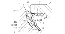
- FIG. 1 is a longitudinal sectional view showing an embodiment of a wheel bearing device according to the present invention
- FIG. 2 is an enlarged view of a main part showing one seal of FIG. 1
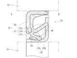
- FIG. 3 is a diagram showing the other seal of FIG. 4
- (a) is a cross-sectional view showing the slinger alone of FIG. 3
- (b) is a view taken along arrow IVb of (a)
- (c) is a view taken along arrow IVc of (a).
- the side closer to the outer side of the vehicle when assembled to the vehicle is referred to as the outer side (left side in FIG. 1), and the side closer to the center is referred to as the inner side (right side in FIG. 1).
- the inner member 1 includes a hub ring 2 and an inner ring 3 press-fitted into the hub ring 2.
- the hub wheel 2 integrally has a wheel mounting flange 4 for mounting a wheel (not shown) at an end on the outer side, and a hub bolt for fixing the wheel at a circumferentially equidistant position of the wheel mounting flange 4. 5 is planted. Further, one (outer side) inner rolling surface 2a and a cylindrical small-diameter step portion 2b extending in the axial direction from the inner rolling surface 2a are formed on the outer periphery of the hub wheel 2, and serrations ( Or a spline) 2c is formed.
- the inner ring 3 is formed with the other (inner side) inner raceway surface 3a on the outer periphery, and is press-fitted into the small-diameter step portion 2b of the hub ring 2 through a predetermined squeeze.
- the hub wheel 2 is formed of medium and high carbon steel containing carbon of 0.40 to 0.80% by weight such as S53C, and includes a base portion 11 on the inner side of the wheel mounting flange 4 serving as a seal land portion of the seal 8 described later,
- the surface hardness is set to a range of 58 to 64 HRC by induction hardening from the inner side rolling surface 2a on the outer side to the small diameter step portion 2b.
- the inner ring 3 and the rolling element 6 are made of high carbon chrome bearing steel such as SUJ2, and are hardened in the range of 58 to 64 HRC to the core by quenching.
- the outer member 10 integrally has a vehicle body mounting flange 10b for mounting to a vehicle body (not shown) on the outer periphery, and a double row facing the inner rolling surfaces 2a, 3a of the inner member 1 on the inner periphery.
- the outer rolling surfaces 10a and 10a are integrally formed.
- This outer member 10 is formed of medium and high carbon steel containing 0.40 to 0.80% by weight of carbon such as S53C, as in the case of the hub wheel 2, and at least the double row outer raceway surfaces 10a and 10a are formed by induction hardening.
- the surface hardness is set in the range of 58 to 64 HRC.
- the double row rolling elements 6 and 6 are accommodated between each rolling surface 10a, 2a and 10a, 3a, and these double row rolling elements 6 and 6 are rollably hold
- Seals 8 and 9 are attached to the opening of the annular space formed between the outer member 10 and the inner member 1, and leakage of lubricating grease sealed inside the bearing and rainwater and dust from the outside. Etc. are prevented from entering the inside of the bearing.
- the wheel bearing apparatus comprised by the double row angular contact ball bearing which used the ball for the rolling element 6 was illustrated here, it is not restricted to this,
- the double row tapered roller bearing which used the tapered roller for the rolling element 6 may consist of.
- a third generation structure in which the inner raceway surface 2a is formed directly on the outer periphery of the hub wheel 2 is illustrated, but although not shown, a pair of inner rings are press-fitted and fixed to the small-diameter step portion of the hub wheel. It may be a first generation or second generation structure.
- the outer-side seal 8 is an integral seal comprising a cored bar 12 and a seal member 13 integrally vulcanized and bonded to the cored bar 12 as shown in an enlarged view in FIG. It is configured.
- the core 12 is made of a ferritic stainless steel plate (JIS standard SUS430 or the like), an austenitic stainless steel plate (JIS standard SUS304 or the like), or a rust-proof cold rolled steel plate (JIS standard SPCC system or the like).
- a cylindrical fitting portion 12a having a substantially L-shaped cross section by press working and press-fitted into the inner periphery of the end portion of the outer member 10 through a predetermined shimiro, and an end portion of the fitting portion 12a And an inner diameter portion 12b extending inward in the radial direction.
- the sealing member 13 wraps around and joins so that the outer surface ranging from the internal diameter part 12b to the fitting part 12a may be formed, and the annular convex part 14 is formed.
- the annular convex portion 14 gradually increases in diameter toward the outer end surface 10c side of the outer member 10, is formed in a tapered surface having a predetermined inclination angle ⁇ , and is formed on the fitting portion 12a of the core metal 12. It is set to a predetermined projection amount ⁇ that is slightly larger than the outer diameter, and is press-fitted into the end inner peripheral surface 10d of the outer member 10 through a predetermined shimiro.
- a predetermined projection amount ⁇ that is slightly larger than the outer diameter, and is press-fitted into the end inner peripheral surface 10d of the outer member 10 through a predetermined shimiro.
- the inclination angle ⁇ of the annular convex portion 14 is set in the range of 5 to 15 °, and the protrusion amount ⁇ of the annular convex portion 14 is set in the range of 0.25 to 0.30 mm.
- the inclination angle ⁇ exceeds 15 °, the resistance at the time of press-fitting increases and there is a risk of damage, and if it is less than 5 °, the effect is halved. Further, if the protrusion amount ⁇ exceeds 0.30 mm, the resistance at the time of press-fitting is increased, and there is a possibility that the rubber of the seal member may be cut. If it is less than 0.25 mm, the airtight effect is reduced, which is not preferable.
- the seal member 13 is made of a synthetic rubber such as NBR (acrylonitrile-butadiene rubber), extends in a radially outward direction, and slidably contacts the base 11 of the wheel mounting flange 4 formed in an arc shape. And a dust lip 13b and a grease lip 13c extending obliquely inwardly of the bearing.
- NBR acrylonitrile-butadiene rubber
- HNBR hydrogenated acrylonitrile butadiene rubber
- EPDM ethylene propylene rubber
- etc. having excellent heat resistance, heat resistance, chemical resistance, etc.
- ACM polyacrylic rubber
- FKM fluororubber
- silicon rubber which are excellent in the above.
- the grease A sealed in the bearing portion has a base oil kinematic viscosity at 40 ° C. of 30 to 170 mm 2 / s and a penetration of 270 to 300.
- the base oil viscosity at 40 ° C. of the grease applied to the seal is It was confirmed that the torque was reduced by making the grease to be sealed in the bearing part 70% or less of the base oil viscosity at 40 ° C.
- the bearing life was inferior to the current specification.
- the grease and the thickener sealed in the wheel bearing are the same in the sliding contact portion of the seal lip, but the blending degree is 350 or less and the base oil kinematic viscosity at 40 ° C. is the wheel bearing.
- the friction torque of the lip is reduced, the rotational torque of the seal is reduced while ensuring the bearing performance, and the fluidity of the grease is suppressed.
- a seal that does not mix with the grease of the bearing portion can be provided. If the penetration level exceeds 350, the grease may scatter due to centrifugal force. Therefore, the penetration level is set to 350 or less in order to give the grease some holding power.
- the viscosity is set to 70% or less with respect to the grease enclosed in the wheel bearing.
- the grease applied to the seal lip can suppress the increase in the starting torque of the seal 8 due to the high viscosity of the base oil or the solidification below the freezing point by mixing mineral oil and synthetic oil as the base oil.
- the pour point of the base oil can be adjusted to be within a predetermined temperature range ( ⁇ 65 to ⁇ 12.5 ° C.).
- This type of wheel bearing is used where there is a risk of rainwater intrusion, so to ensure the durability of the bearing, it is saturated by adding a dispersant that can disperse water as fine particles in the grease.
- Grease with controlled moisture content is used.
- grease with controlled saturation moisture content cannot prevent the formation of oil film by grease because the infiltrated water is dispersed in the grease as fine water particles and is trapped in the continuous phase grease. This is considered to improve the durability of the bearing.
- the present invention is based on such findings. Specifically, a high oil film formation rate can be obtained when the saturated water content is in the range of 30 to 60% by weight, preferably in the range of 40 to 50% by weight.
- a surfactant can be used as the dispersant capable of controlling the saturated water content in the grease according to the present invention.
- the surfactant is used to disperse the moisture in the grease and make the moisture harmless so that the oil film does not break or rust even if water enters the bearing or the seal 8.
- the water that has entered the grease is dispersed in the grease as fine water particles by the surfactant. Since grease can exist as a continuous phase, it is thought that oil film breakage does not occur.
- Specific examples of the surfactant include polyalkylene glycols, carboxylic acid alkylene glycols, and carboxylic acid polyalkylene glycols.
- rusting of the lip sliding portion can be effectively suppressed by mixing a rust preventive agent such as sulfonates and esters into the grease 15 applied to the seal lip portion.
- the inner side seal 9 is called a so-called pack seal, which is composed of an annular seal plate 16 and a slinger 17 that are formed in a substantially L-shaped cross section and are arranged to face each other. This constitutes a composite seal.
- the annular seal plate 16 includes a cored bar 18 press-fitted into the inner periphery of the end of the outer member 10, and a seal member 19 integrally vulcanized and bonded to the cored bar 18.
- the cored bar 18 is formed by pressing from a ferritic stainless steel plate, an austenitic stainless steel plate, or a cold-rolled steel plate that has been rust-proofed, and has a substantially L-shaped cross section. It has a cylindrical fitting portion 18a that is press-fitted through a predetermined shimoshiro, and an inner diameter portion 18b that extends radially inward from the end of the fitting portion 18a.
- tip part of the fitting part 18a of the metal core 18 is formed thinly, and the sealing member 19 wraps around and joins so that this front-end
- the slinger 17 is formed into a substantially L-shaped section by pressing from a ferritic stainless steel plate, an austenitic stainless steel plate, or a cold-rolled steel plate that has been subjected to rust prevention treatment, and is pressed into the outer peripheral surface of the inner ring 3.
- the seal member 19 is made of synthetic rubber such as NBR, and has a side lip 19a that is in sliding contact with a side surface on the outer side of the standing plate portion 17b of the slinger 17 via a predetermined axial squeeze, and a forked shape on the inner diameter side of the side lip 19a. And a grease lip 19b and a dust lip 19c that are in sliding contact with the outer peripheral surface of the cylindrical portion 17a of the slinger 17 via a predetermined radial squeeze.
- NBR synthetic rubber
- the grease 15 is applied between the side lip 19a and the grease lip 19b and the dust lip 19c. Similar to the outer seal 8, the grease 15 is different from the grease enclosed for lubricating the bearing portion. Thus, the grease 15 applied to the seal lip is made different from the grease sealed in the bearing portion, and the base oil dynamic viscosity at 40 ° C. of the grease 15 is set to 70% or less of the grease sealed in the bearing portion. Thus, the friction torque of the lip can be reduced, and the rotational torque of the seal 9 can be reduced.
- innumerable dimples 21 are formed at the lip sliding contact portion of the slinger 17 by shot blasting.
- the slinger 17 is placed on a rotating jig (not shown), and the rotating jig is turned in a state where the shot blasting nozzle 22 is opposed to the slinger 17, so that a medium such as steel beads is used. Is carried out by spraying.
- shot blasting is performed while moving the nozzle 22 to a predetermined range under the conditions of a particle size of the steel beads of 20 to 100 ⁇ m, an injection time of about 90 seconds, and an injection pressure of 1 to 3 kg / cm 2 .
- the steel plate used as the material of the slinger 17 usually has a surface roughness of a maximum height Rz 2.4 or less, and the surface is roughened by shot blasting, specifically, the range of the maximum height Rz 1-9. Is set to The maximum height Rz is one of JIS roughness shape parameters (JIS B0601-2001), and is the sum of the highest value and the lowest value from the average line.
- Innumerable dimples 21 are formed in advance on the sliding contact surface of the slinger 17 in this manner, so that the lubricity on the sliding contact surface is improved, the lip sliding resistance is reduced, the rotational torque is reduced, and the dimple 21
- the surface area is increased, the holding power of the grease 15 is increased, wear of each lip and heat generation of the lip sliding portion are suppressed, and the sealability and durability of the seal 9 can be improved over a long period of time.
- the wheel bearing device according to the present invention can be applied to first to third generation wheel bearing devices of the inner ring rotation type.
Landscapes
- Engineering & Computer Science (AREA)
- General Engineering & Computer Science (AREA)
- Mechanical Engineering (AREA)
- Chemical & Material Sciences (AREA)
- Chemical Kinetics & Catalysis (AREA)
- General Chemical & Material Sciences (AREA)
- Oil, Petroleum & Natural Gas (AREA)
- Organic Chemistry (AREA)
- Rolling Contact Bearings (AREA)
- Sealing Of Bearings (AREA)
Priority Applications (3)
| Application Number | Priority Date | Filing Date | Title |
|---|---|---|---|
| CN201380008220.2A CN104160167B (zh) | 2012-02-07 | 2013-02-06 | 车轮轴承装置 |
| EP13746656.1A EP2813721B1 (de) | 2012-02-07 | 2013-02-06 | Radlagervorrichtung |
| US14/452,881 US9623703B2 (en) | 2012-02-07 | 2014-08-06 | Wheel bearing apparatus for a vehicle |
Applications Claiming Priority (2)
| Application Number | Priority Date | Filing Date | Title |
|---|---|---|---|
| JP2012024126A JP5918556B2 (ja) | 2012-02-07 | 2012-02-07 | 車輪用軸受装置 |
| JP2012-024126 | 2012-02-07 |
Related Child Applications (1)
| Application Number | Title | Priority Date | Filing Date |
|---|---|---|---|
| US14/452,881 Continuation US9623703B2 (en) | 2012-02-07 | 2014-08-06 | Wheel bearing apparatus for a vehicle |
Publications (1)
| Publication Number | Publication Date |
|---|---|
| WO2013118782A1 true WO2013118782A1 (ja) | 2013-08-15 |
Family
ID=48947543
Family Applications (1)
| Application Number | Title | Priority Date | Filing Date |
|---|---|---|---|
| PCT/JP2013/052767 WO2013118782A1 (ja) | 2012-02-07 | 2013-02-06 | 車輪用軸受装置 |
Country Status (5)
| Country | Link |
|---|---|
| US (1) | US9623703B2 (de) |
| EP (1) | EP2813721B1 (de) |
| JP (1) | JP5918556B2 (de) |
| CN (1) | CN104160167B (de) |
| WO (1) | WO2013118782A1 (de) |
Cited By (1)
| Publication number | Priority date | Publication date | Assignee | Title |
|---|---|---|---|---|
| WO2016190175A1 (ja) * | 2015-05-22 | 2016-12-01 | Nok株式会社 | 密封装置 |
Families Citing this family (13)
| Publication number | Priority date | Publication date | Assignee | Title |
|---|---|---|---|---|
| US10054226B1 (en) * | 2015-11-25 | 2018-08-21 | Billy Dean Watson | Mechanical sealing system |
| JP6782600B2 (ja) * | 2016-10-04 | 2020-11-11 | ナブテスコ株式会社 | シール及びシール機構 |
| US10935137B2 (en) * | 2016-11-10 | 2021-03-02 | Hutchinson | Seal assembly, roller bearing comprising such an assembly, and method for manufacturing this assembly |
| EP3546806B1 (de) | 2016-11-25 | 2023-03-15 | NOK Corporation | Dichtungsvorrichtung |
| EP3536997B1 (de) * | 2016-11-25 | 2022-06-01 | NOK Corporation | Dichtungsvorrichtung und dichtungsstruktur |
| JP6926812B2 (ja) * | 2017-08-14 | 2021-08-25 | 日本精工株式会社 | ハブユニット軸受及びハブユニット軸受の組立方法 |
| JP7285020B2 (ja) * | 2017-10-06 | 2023-06-01 | 内山工業株式会社 | 密封装置 |
| JP7024994B2 (ja) * | 2017-10-06 | 2022-02-24 | 内山工業株式会社 | 密封装置 |
| DE102017220989A1 (de) * | 2017-11-23 | 2018-11-29 | Zf Friedrichshafen Ag | Ölführungsanordnung für ein Getriebegehäuse |
| JP6967087B2 (ja) * | 2017-12-27 | 2021-11-17 | Nok株式会社 | 密封装置 |
| DE102018200603A1 (de) | 2018-01-15 | 2019-07-18 | Audi Ag | Dichtungsanordnung für eine Radlageranordnung eines Kraftfahrzeugs |
| EP3882497B1 (de) * | 2018-11-12 | 2024-08-21 | NOK Corporation | Abdichtungsvorrichtung und schmierfettanhaftungsverfahren |
| DE102019217379A1 (de) * | 2019-11-11 | 2021-05-12 | Aktiebolaget Skf | Wälzlageranordnung |
Citations (7)
| Publication number | Priority date | Publication date | Assignee | Title |
|---|---|---|---|---|
| JP2004353710A (ja) * | 2003-05-27 | 2004-12-16 | Nsk Ltd | 転がり軸受 |
| JP2006083878A (ja) * | 2004-09-14 | 2006-03-30 | Nsk Ltd | 車輪用転がり軸受 |
| JP2008025668A (ja) | 2006-07-19 | 2008-02-07 | Koyo Sealing Techno Co Ltd | 密封装置 |
| JP2010084142A (ja) * | 2008-09-05 | 2010-04-15 | Ntn Corp | グリース組成物および該グリース組成物を封入した転がり軸受 |
| JP2010159791A (ja) * | 2009-01-07 | 2010-07-22 | Ntn Corp | 車輪用軸受シールおよびこれを備えた車輪用軸受装置 |
| JP2011069422A (ja) * | 2009-09-25 | 2011-04-07 | Ntn Corp | 車輪用軸受装置 |
| JP2011185342A (ja) * | 2010-03-08 | 2011-09-22 | Jtekt Corp | 転がり軸受装置 |
Family Cites Families (12)
| Publication number | Priority date | Publication date | Assignee | Title |
|---|---|---|---|---|
| US7618194B2 (en) * | 2004-04-09 | 2009-11-17 | Ntn Corporation | Wheel bearing apparatus incorporated with a wheel speed detecting apparatus |
| JP2005324714A (ja) * | 2004-05-17 | 2005-11-24 | Ntn Corp | 車輪用軸受装置 |
| KR20070039592A (ko) * | 2004-08-19 | 2007-04-12 | 닛본 세이고 가부시끼가이샤 | 구름 베어링 |
| JP2006200616A (ja) * | 2005-01-20 | 2006-08-03 | Ntn Corp | 軸受用密封装置および耐寒性密封装置付き転がり軸受 |
| JP4925398B2 (ja) * | 2005-05-19 | 2012-04-25 | 内山工業株式会社 | 密封装置 |
| JP4925397B2 (ja) * | 2005-05-19 | 2012-04-25 | 内山工業株式会社 | 密封装置 |
| JP4942321B2 (ja) * | 2005-09-28 | 2012-05-30 | Ntn株式会社 | ハブベアリング |
| WO2007037308A1 (ja) * | 2005-09-28 | 2007-04-05 | Ntn Corporation | 耐水グリース、該グリース封入転がり軸受およびハブベアリング |
| WO2008139738A1 (ja) * | 2007-05-16 | 2008-11-20 | Ntn Corporation | 回転速度検出装置付き車輪用軸受装置 |
| CN103047295B (zh) * | 2007-11-09 | 2015-04-29 | Ntn株式会社 | 车轮用轴承 |
| JP5800449B2 (ja) * | 2008-03-25 | 2015-10-28 | Jx日鉱日石エネルギー株式会社 | 潤滑油基油及びその製造方法並びに潤滑油組成物 |
| WO2010027019A1 (ja) | 2008-09-05 | 2010-03-11 | Ntn株式会社 | グリース組成物、該グリース組成物を封入した転がり軸受および自在継手 |
-
2012
- 2012-02-07 JP JP2012024126A patent/JP5918556B2/ja active Active
-
2013
- 2013-02-06 CN CN201380008220.2A patent/CN104160167B/zh active Active
- 2013-02-06 EP EP13746656.1A patent/EP2813721B1/de active Active
- 2013-02-06 WO PCT/JP2013/052767 patent/WO2013118782A1/ja active Application Filing
-
2014
- 2014-08-06 US US14/452,881 patent/US9623703B2/en active Active
Patent Citations (7)
| Publication number | Priority date | Publication date | Assignee | Title |
|---|---|---|---|---|
| JP2004353710A (ja) * | 2003-05-27 | 2004-12-16 | Nsk Ltd | 転がり軸受 |
| JP2006083878A (ja) * | 2004-09-14 | 2006-03-30 | Nsk Ltd | 車輪用転がり軸受 |
| JP2008025668A (ja) | 2006-07-19 | 2008-02-07 | Koyo Sealing Techno Co Ltd | 密封装置 |
| JP2010084142A (ja) * | 2008-09-05 | 2010-04-15 | Ntn Corp | グリース組成物および該グリース組成物を封入した転がり軸受 |
| JP2010159791A (ja) * | 2009-01-07 | 2010-07-22 | Ntn Corp | 車輪用軸受シールおよびこれを備えた車輪用軸受装置 |
| JP2011069422A (ja) * | 2009-09-25 | 2011-04-07 | Ntn Corp | 車輪用軸受装置 |
| JP2011185342A (ja) * | 2010-03-08 | 2011-09-22 | Jtekt Corp | 転がり軸受装置 |
Cited By (2)
| Publication number | Priority date | Publication date | Assignee | Title |
|---|---|---|---|---|
| WO2016190175A1 (ja) * | 2015-05-22 | 2016-12-01 | Nok株式会社 | 密封装置 |
| JPWO2016190175A1 (ja) * | 2015-05-22 | 2018-02-15 | Nok株式会社 | 密封装置 |
Also Published As
| Publication number | Publication date |
|---|---|
| US20140346850A1 (en) | 2014-11-27 |
| JP2013160343A (ja) | 2013-08-19 |
| US9623703B2 (en) | 2017-04-18 |
| EP2813721A4 (de) | 2016-03-02 |
| CN104160167A (zh) | 2014-11-19 |
| CN104160167B (zh) | 2017-03-08 |
| EP2813721A1 (de) | 2014-12-17 |
| EP2813721B1 (de) | 2018-11-21 |
| JP5918556B2 (ja) | 2016-05-18 |
Similar Documents
| Publication | Publication Date | Title |
|---|---|---|
| JP5918556B2 (ja) | 車輪用軸受装置 | |
| US9090122B2 (en) | Wheel bearing apparatus for a vehicle | |
| WO2011115254A1 (ja) | 車輪用軸受装置 | |
| JP2012207769A (ja) | 車輪用軸受装置 | |
| JP2015110958A (ja) | 密封装置およびこれを備えた車輪用軸受装置 | |
| JP2009197884A (ja) | 車輪用軸受装置 | |
| JP5557668B2 (ja) | 車輪用軸受装置 | |
| JP2009197883A (ja) | 車輪用軸受装置 | |
| US20090154855A1 (en) | Wheel bearing apparatus for a vehicle | |
| JP2015152030A (ja) | 密封装置およびこれを備えた車輪用軸受装置 | |
| JP2011069422A (ja) | 車輪用軸受装置 | |
| JP5771478B2 (ja) | 車輪用軸受シール | |
| JP2007211792A (ja) | 車輪用軸受 | |
| JP5414964B2 (ja) | 車輪用軸受装置 | |
| JP2012017019A (ja) | 車輪用軸受装置 | |
| JP2008157327A (ja) | 車輪用軸受装置 | |
| JP5083861B2 (ja) | 車輪用軸受装置 | |
| JP5995501B2 (ja) | 車輪用軸受装置 | |
| JP2018080840A (ja) | 密封装置およびこれを備えた車輪用軸受装置 | |
| JP2015148253A (ja) | 車輪用軸受装置 | |
| JP2013224718A (ja) | 車輪用軸受装置 | |
| JP2015068350A (ja) | 車輪用軸受シール | |
| JP2013040664A (ja) | 車輪用軸受装置 | |
| JP4936373B2 (ja) | 車輪用軸受装置 | |
| JP2009248625A (ja) | 車輪用軸受装置 |
Legal Events
| Date | Code | Title | Description |
|---|---|---|---|
| 121 | Ep: the epo has been informed by wipo that ep was designated in this application |
Ref document number: 13746656 Country of ref document: EP Kind code of ref document: A1 |
|
| NENP | Non-entry into the national phase |
Ref country code: DE |
|
| WWE | Wipo information: entry into national phase |
Ref document number: 2013746656 Country of ref document: EP |