WO2013088535A1 - 車両用情報伝達装置 - Google Patents
車両用情報伝達装置 Download PDFInfo
- Publication number
- WO2013088535A1 WO2013088535A1 PCT/JP2011/078963 JP2011078963W WO2013088535A1 WO 2013088535 A1 WO2013088535 A1 WO 2013088535A1 JP 2011078963 W JP2011078963 W JP 2011078963W WO 2013088535 A1 WO2013088535 A1 WO 2013088535A1
- Authority
- WO
- WIPO (PCT)
- Prior art keywords
- display
- danger
- state
- vehicle
- avoidance
- Prior art date
Links
- 230000005540 biological transmission Effects 0.000 title claims abstract description 23
- 238000001514 detection method Methods 0.000 claims description 74
- 230000009471 action Effects 0.000 claims description 60
- 238000010586 diagram Methods 0.000 description 25
- 230000006399 behavior Effects 0.000 description 17
- 230000008859 change Effects 0.000 description 16
- 238000000034 method Methods 0.000 description 5
- 238000012545 processing Methods 0.000 description 5
- 230000008569 process Effects 0.000 description 4
- 230000005043 peripheral vision Effects 0.000 description 2
- 230000007704 transition Effects 0.000 description 2
- 238000012790 confirmation Methods 0.000 description 1
- 230000003247 decreasing effect Effects 0.000 description 1
- 238000003745 diagnosis Methods 0.000 description 1
- 230000000694 effects Effects 0.000 description 1
- 210000004394 hip joint Anatomy 0.000 description 1
- 230000006872 improvement Effects 0.000 description 1
- 239000004973 liquid crystal related substance Substances 0.000 description 1
- 238000004519 manufacturing process Methods 0.000 description 1
- 238000005259 measurement Methods 0.000 description 1
- 238000012806 monitoring device Methods 0.000 description 1
- 230000002265 prevention Effects 0.000 description 1
- 230000004044 response Effects 0.000 description 1
Images


Classifications
-
- B—PERFORMING OPERATIONS; TRANSPORTING
- B60—VEHICLES IN GENERAL
- B60Q—ARRANGEMENT OF SIGNALLING OR LIGHTING DEVICES, THE MOUNTING OR SUPPORTING THEREOF OR CIRCUITS THEREFOR, FOR VEHICLES IN GENERAL
- B60Q9/00—Arrangement or adaptation of signal devices not provided for in one of main groups B60Q1/00 - B60Q7/00, e.g. haptic signalling
- B60Q9/008—Arrangement or adaptation of signal devices not provided for in one of main groups B60Q1/00 - B60Q7/00, e.g. haptic signalling for anti-collision purposes
-
- G—PHYSICS
- G08—SIGNALLING
- G08G—TRAFFIC CONTROL SYSTEMS
- G08G1/00—Traffic control systems for road vehicles
- G08G1/16—Anti-collision systems
- G08G1/165—Anti-collision systems for passive traffic, e.g. including static obstacles, trees
-
- B—PERFORMING OPERATIONS; TRANSPORTING
- B60—VEHICLES IN GENERAL
- B60K—ARRANGEMENT OR MOUNTING OF PROPULSION UNITS OR OF TRANSMISSIONS IN VEHICLES; ARRANGEMENT OR MOUNTING OF PLURAL DIVERSE PRIME-MOVERS IN VEHICLES; AUXILIARY DRIVES FOR VEHICLES; INSTRUMENTATION OR DASHBOARDS FOR VEHICLES; ARRANGEMENTS IN CONNECTION WITH COOLING, AIR INTAKE, GAS EXHAUST OR FUEL SUPPLY OF PROPULSION UNITS IN VEHICLES
- B60K35/00—Instruments specially adapted for vehicles; Arrangement of instruments in or on vehicles
- B60K35/20—Output arrangements, i.e. from vehicle to user, associated with vehicle functions or specially adapted therefor
- B60K35/28—Output arrangements, i.e. from vehicle to user, associated with vehicle functions or specially adapted therefor characterised by the type of the output information, e.g. video entertainment or vehicle dynamics information; characterised by the purpose of the output information, e.g. for attracting the attention of the driver
- B60K35/285—Output arrangements, i.e. from vehicle to user, associated with vehicle functions or specially adapted therefor characterised by the type of the output information, e.g. video entertainment or vehicle dynamics information; characterised by the purpose of the output information, e.g. for attracting the attention of the driver for improving awareness by directing driver's gaze direction or eye points
-
- B—PERFORMING OPERATIONS; TRANSPORTING
- B60—VEHICLES IN GENERAL
- B60K—ARRANGEMENT OR MOUNTING OF PROPULSION UNITS OR OF TRANSMISSIONS IN VEHICLES; ARRANGEMENT OR MOUNTING OF PLURAL DIVERSE PRIME-MOVERS IN VEHICLES; AUXILIARY DRIVES FOR VEHICLES; INSTRUMENTATION OR DASHBOARDS FOR VEHICLES; ARRANGEMENTS IN CONNECTION WITH COOLING, AIR INTAKE, GAS EXHAUST OR FUEL SUPPLY OF PROPULSION UNITS IN VEHICLES
- B60K35/00—Instruments specially adapted for vehicles; Arrangement of instruments in or on vehicles
- B60K35/20—Output arrangements, i.e. from vehicle to user, associated with vehicle functions or specially adapted therefor
- B60K35/29—Instruments characterised by the way in which information is handled, e.g. showing information on plural displays or prioritising information according to driving conditions
-
- B—PERFORMING OPERATIONS; TRANSPORTING
- B60—VEHICLES IN GENERAL
- B60K—ARRANGEMENT OR MOUNTING OF PROPULSION UNITS OR OF TRANSMISSIONS IN VEHICLES; ARRANGEMENT OR MOUNTING OF PLURAL DIVERSE PRIME-MOVERS IN VEHICLES; AUXILIARY DRIVES FOR VEHICLES; INSTRUMENTATION OR DASHBOARDS FOR VEHICLES; ARRANGEMENTS IN CONNECTION WITH COOLING, AIR INTAKE, GAS EXHAUST OR FUEL SUPPLY OF PROPULSION UNITS IN VEHICLES
- B60K35/00—Instruments specially adapted for vehicles; Arrangement of instruments in or on vehicles
- B60K35/70—Instrument provisions for avoiding injuries to vehicle occupants in case of accidents
-
- B—PERFORMING OPERATIONS; TRANSPORTING
- B60—VEHICLES IN GENERAL
- B60K—ARRANGEMENT OR MOUNTING OF PROPULSION UNITS OR OF TRANSMISSIONS IN VEHICLES; ARRANGEMENT OR MOUNTING OF PLURAL DIVERSE PRIME-MOVERS IN VEHICLES; AUXILIARY DRIVES FOR VEHICLES; INSTRUMENTATION OR DASHBOARDS FOR VEHICLES; ARRANGEMENTS IN CONNECTION WITH COOLING, AIR INTAKE, GAS EXHAUST OR FUEL SUPPLY OF PROPULSION UNITS IN VEHICLES
- B60K35/00—Instruments specially adapted for vehicles; Arrangement of instruments in or on vehicles
- B60K35/80—Arrangements for controlling instruments
- B60K35/81—Arrangements for controlling instruments for controlling displays
-
- G—PHYSICS
- G08—SIGNALLING
- G08G—TRAFFIC CONTROL SYSTEMS
- G08G1/00—Traffic control systems for road vehicles
- G08G1/16—Anti-collision systems
- G08G1/166—Anti-collision systems for active traffic, e.g. moving vehicles, pedestrians, bikes
-
- B—PERFORMING OPERATIONS; TRANSPORTING
- B60—VEHICLES IN GENERAL
- B60K—ARRANGEMENT OR MOUNTING OF PROPULSION UNITS OR OF TRANSMISSIONS IN VEHICLES; ARRANGEMENT OR MOUNTING OF PLURAL DIVERSE PRIME-MOVERS IN VEHICLES; AUXILIARY DRIVES FOR VEHICLES; INSTRUMENTATION OR DASHBOARDS FOR VEHICLES; ARRANGEMENTS IN CONNECTION WITH COOLING, AIR INTAKE, GAS EXHAUST OR FUEL SUPPLY OF PROPULSION UNITS IN VEHICLES
- B60K2360/00—Indexing scheme associated with groups B60K35/00 or B60K37/00 relating to details of instruments or dashboards
- B60K2360/16—Type of output information
- B60K2360/165—Videos and animations
-
- B—PERFORMING OPERATIONS; TRANSPORTING
- B60—VEHICLES IN GENERAL
- B60K—ARRANGEMENT OR MOUNTING OF PROPULSION UNITS OR OF TRANSMISSIONS IN VEHICLES; ARRANGEMENT OR MOUNTING OF PLURAL DIVERSE PRIME-MOVERS IN VEHICLES; AUXILIARY DRIVES FOR VEHICLES; INSTRUMENTATION OR DASHBOARDS FOR VEHICLES; ARRANGEMENTS IN CONNECTION WITH COOLING, AIR INTAKE, GAS EXHAUST OR FUEL SUPPLY OF PROPULSION UNITS IN VEHICLES
- B60K2360/00—Indexing scheme associated with groups B60K35/00 or B60K37/00 relating to details of instruments or dashboards
- B60K2360/16—Type of output information
- B60K2360/166—Navigation
-
- B—PERFORMING OPERATIONS; TRANSPORTING
- B60—VEHICLES IN GENERAL
- B60K—ARRANGEMENT OR MOUNTING OF PROPULSION UNITS OR OF TRANSMISSIONS IN VEHICLES; ARRANGEMENT OR MOUNTING OF PLURAL DIVERSE PRIME-MOVERS IN VEHICLES; AUXILIARY DRIVES FOR VEHICLES; INSTRUMENTATION OR DASHBOARDS FOR VEHICLES; ARRANGEMENTS IN CONNECTION WITH COOLING, AIR INTAKE, GAS EXHAUST OR FUEL SUPPLY OF PROPULSION UNITS IN VEHICLES
- B60K2360/00—Indexing scheme associated with groups B60K35/00 or B60K37/00 relating to details of instruments or dashboards
- B60K2360/16—Type of output information
- B60K2360/167—Vehicle dynamics information
-
- B—PERFORMING OPERATIONS; TRANSPORTING
- B60—VEHICLES IN GENERAL
- B60K—ARRANGEMENT OR MOUNTING OF PROPULSION UNITS OR OF TRANSMISSIONS IN VEHICLES; ARRANGEMENT OR MOUNTING OF PLURAL DIVERSE PRIME-MOVERS IN VEHICLES; AUXILIARY DRIVES FOR VEHICLES; INSTRUMENTATION OR DASHBOARDS FOR VEHICLES; ARRANGEMENTS IN CONNECTION WITH COOLING, AIR INTAKE, GAS EXHAUST OR FUEL SUPPLY OF PROPULSION UNITS IN VEHICLES
- B60K2360/00—Indexing scheme associated with groups B60K35/00 or B60K37/00 relating to details of instruments or dashboards
- B60K2360/16—Type of output information
- B60K2360/176—Camera images
-
- B—PERFORMING OPERATIONS; TRANSPORTING
- B60—VEHICLES IN GENERAL
- B60K—ARRANGEMENT OR MOUNTING OF PROPULSION UNITS OR OF TRANSMISSIONS IN VEHICLES; ARRANGEMENT OR MOUNTING OF PLURAL DIVERSE PRIME-MOVERS IN VEHICLES; AUXILIARY DRIVES FOR VEHICLES; INSTRUMENTATION OR DASHBOARDS FOR VEHICLES; ARRANGEMENTS IN CONNECTION WITH COOLING, AIR INTAKE, GAS EXHAUST OR FUEL SUPPLY OF PROPULSION UNITS IN VEHICLES
- B60K2360/00—Indexing scheme associated with groups B60K35/00 or B60K37/00 relating to details of instruments or dashboards
- B60K2360/16—Type of output information
- B60K2360/178—Warnings
-
- B—PERFORMING OPERATIONS; TRANSPORTING
- B60—VEHICLES IN GENERAL
- B60K—ARRANGEMENT OR MOUNTING OF PROPULSION UNITS OR OF TRANSMISSIONS IN VEHICLES; ARRANGEMENT OR MOUNTING OF PLURAL DIVERSE PRIME-MOVERS IN VEHICLES; AUXILIARY DRIVES FOR VEHICLES; INSTRUMENTATION OR DASHBOARDS FOR VEHICLES; ARRANGEMENTS IN CONNECTION WITH COOLING, AIR INTAKE, GAS EXHAUST OR FUEL SUPPLY OF PROPULSION UNITS IN VEHICLES
- B60K2360/00—Indexing scheme associated with groups B60K35/00 or B60K37/00 relating to details of instruments or dashboards
- B60K2360/18—Information management
- B60K2360/186—Displaying information according to relevancy
-
- B—PERFORMING OPERATIONS; TRANSPORTING
- B60—VEHICLES IN GENERAL
- B60K—ARRANGEMENT OR MOUNTING OF PROPULSION UNITS OR OF TRANSMISSIONS IN VEHICLES; ARRANGEMENT OR MOUNTING OF PLURAL DIVERSE PRIME-MOVERS IN VEHICLES; AUXILIARY DRIVES FOR VEHICLES; INSTRUMENTATION OR DASHBOARDS FOR VEHICLES; ARRANGEMENTS IN CONNECTION WITH COOLING, AIR INTAKE, GAS EXHAUST OR FUEL SUPPLY OF PROPULSION UNITS IN VEHICLES
- B60K2360/00—Indexing scheme associated with groups B60K35/00 or B60K37/00 relating to details of instruments or dashboards
- B60K2360/18—Information management
- B60K2360/188—Displaying information using colour changes
-
- B—PERFORMING OPERATIONS; TRANSPORTING
- B60—VEHICLES IN GENERAL
- B60K—ARRANGEMENT OR MOUNTING OF PROPULSION UNITS OR OF TRANSMISSIONS IN VEHICLES; ARRANGEMENT OR MOUNTING OF PLURAL DIVERSE PRIME-MOVERS IN VEHICLES; AUXILIARY DRIVES FOR VEHICLES; INSTRUMENTATION OR DASHBOARDS FOR VEHICLES; ARRANGEMENTS IN CONNECTION WITH COOLING, AIR INTAKE, GAS EXHAUST OR FUEL SUPPLY OF PROPULSION UNITS IN VEHICLES
- B60K2360/00—Indexing scheme associated with groups B60K35/00 or B60K37/00 relating to details of instruments or dashboards
- B60K2360/18—Information management
- B60K2360/191—Highlight information
-
- B—PERFORMING OPERATIONS; TRANSPORTING
- B60—VEHICLES IN GENERAL
- B60K—ARRANGEMENT OR MOUNTING OF PROPULSION UNITS OR OF TRANSMISSIONS IN VEHICLES; ARRANGEMENT OR MOUNTING OF PLURAL DIVERSE PRIME-MOVERS IN VEHICLES; AUXILIARY DRIVES FOR VEHICLES; INSTRUMENTATION OR DASHBOARDS FOR VEHICLES; ARRANGEMENTS IN CONNECTION WITH COOLING, AIR INTAKE, GAS EXHAUST OR FUEL SUPPLY OF PROPULSION UNITS IN VEHICLES
- B60K2360/00—Indexing scheme associated with groups B60K35/00 or B60K37/00 relating to details of instruments or dashboards
- B60K2360/20—Optical features of instruments
- B60K2360/21—Optical features of instruments using cameras
-
- B—PERFORMING OPERATIONS; TRANSPORTING
- B60—VEHICLES IN GENERAL
- B60K—ARRANGEMENT OR MOUNTING OF PROPULSION UNITS OR OF TRANSMISSIONS IN VEHICLES; ARRANGEMENT OR MOUNTING OF PLURAL DIVERSE PRIME-MOVERS IN VEHICLES; AUXILIARY DRIVES FOR VEHICLES; INSTRUMENTATION OR DASHBOARDS FOR VEHICLES; ARRANGEMENTS IN CONNECTION WITH COOLING, AIR INTAKE, GAS EXHAUST OR FUEL SUPPLY OF PROPULSION UNITS IN VEHICLES
- B60K2360/00—Indexing scheme associated with groups B60K35/00 or B60K37/00 relating to details of instruments or dashboards
- B60K2360/20—Optical features of instruments
- B60K2360/33—Illumination features
- B60K2360/334—Projection means
-
- B—PERFORMING OPERATIONS; TRANSPORTING
- B60—VEHICLES IN GENERAL
- B60K—ARRANGEMENT OR MOUNTING OF PROPULSION UNITS OR OF TRANSMISSIONS IN VEHICLES; ARRANGEMENT OR MOUNTING OF PLURAL DIVERSE PRIME-MOVERS IN VEHICLES; AUXILIARY DRIVES FOR VEHICLES; INSTRUMENTATION OR DASHBOARDS FOR VEHICLES; ARRANGEMENTS IN CONNECTION WITH COOLING, AIR INTAKE, GAS EXHAUST OR FUEL SUPPLY OF PROPULSION UNITS IN VEHICLES
- B60K2360/00—Indexing scheme associated with groups B60K35/00 or B60K37/00 relating to details of instruments or dashboards
- B60K2360/60—Structural details of dashboards or instruments
- B60K2360/65—Features of dashboards
- B60K2360/652—Crash protection features
-
- B—PERFORMING OPERATIONS; TRANSPORTING
- B60—VEHICLES IN GENERAL
- B60K—ARRANGEMENT OR MOUNTING OF PROPULSION UNITS OR OF TRANSMISSIONS IN VEHICLES; ARRANGEMENT OR MOUNTING OF PLURAL DIVERSE PRIME-MOVERS IN VEHICLES; AUXILIARY DRIVES FOR VEHICLES; INSTRUMENTATION OR DASHBOARDS FOR VEHICLES; ARRANGEMENTS IN CONNECTION WITH COOLING, AIR INTAKE, GAS EXHAUST OR FUEL SUPPLY OF PROPULSION UNITS IN VEHICLES
- B60K35/00—Instruments specially adapted for vehicles; Arrangement of instruments in or on vehicles
- B60K35/20—Output arrangements, i.e. from vehicle to user, associated with vehicle functions or specially adapted therefor
- B60K35/21—Output arrangements, i.e. from vehicle to user, associated with vehicle functions or specially adapted therefor using visual output, e.g. blinking lights or matrix displays
- B60K35/22—Display screens
Definitions
- the present invention relates to a vehicle information transmission device.
- Patent Document 1 discloses a display control device that calculates a recommended route for avoiding an obstacle and displays a recommended route line on the head-up display so as to overlap the recommended route.
- Patent Document 2 and Patent Document 3 can be cited as other prior art documents.
- Patent Document 2 discloses a driving diagnosis device that diagnoses driving of a driver using a travel history.
- Patent Document 3 discloses a vehicle blind spot monitoring device that displays a warning that an obstacle exists in the blind spot area in the vicinity of the position on the driver's line of sight on the windshield.
- Patent Documents 1 and 2 there is still room for improvement in terms of transmitting information related to danger around the host vehicle (for example, whether there is danger) in an easy-to-understand manner without making the driver feel uncomfortable. There was a problem of being.
- the present invention has been made in view of the above circumstances, and provides a vehicle information transmission device capable of transmitting information related to danger around the host vehicle so that the driver can intuitively understand it. With the goal.
- the present invention comprises reference mark display means for displaying a reference mark serving as a reference indicating that the vehicle is in a safe state, and danger display means for displaying the presence or absence of danger to the host vehicle at a relative position with respect to the reference mark.
- the said danger display means is good also as a structure of displaying the direction which has the said danger in the relative position with respect to the said reference mark, when there exists the said danger.
- it further includes an avoidance action detection means for detecting the presence or absence of an avoidance action corresponding to the danger, and the danger display means detects that the avoidance action is detected by the avoidance action detection means. If it is, the presence of the avoidance action may be displayed at the display position of the reference mark.
- the said danger display means is good also as a structure of emphasizing the display of the said danger, when it detects that the said avoidance action does not have the said avoidance action detection means.
- the said danger display means is good also as a structure which changes the display that the said avoidance action exists according to the presence or absence of another danger different from the said danger.
- the present invention displays a reference mark serving as a reference indicating that the vehicle is in a safe state, and displays the presence / absence of danger to the host vehicle at a relative position with respect to the reference mark, the driver can provide information on the danger around the host vehicle. There is an effect that it can be transmitted in an intuitive and easy-to-understand manner.
- FIG. 1 is a block diagram illustrating an example of a configuration of a vehicle information transmission system according to the present embodiment.
- FIG. 2 is a diagram illustrating an example of the mounting position of the display device 10.
- FIG. 3 is a diagram illustrating an example of the display screen 10a in the initial state.
- FIG. 4 is a diagram illustrating a change example of the display state of the vehicle state display graphic 10c.
- FIG. 5 is a diagram illustrating an example of a change in the display state of the vehicle state display graphic 10c.
- FIG. 6 is a diagram illustrating a change example of the display state of the vehicle state display graphic 10c.
- FIG. 7 is a diagram illustrating an example of a traffic scene.
- FIG. 1 is a block diagram illustrating an example of a configuration of a vehicle information transmission system according to the present embodiment.
- FIG. 2 is a diagram illustrating an example of the mounting position of the display device 10.
- FIG. 3 is a diagram illustrating an example of the display screen 10a in the
- FIG. 8 is a diagram illustrating a change example of the display state of the own vehicle state display graphic 10c.
- FIG. 9 is a diagram illustrating an example of a traffic scene.
- FIG. 10 is a flowchart illustrating an example of main processing executed in the vehicle information transmission system according to the present embodiment.
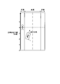
- FIG. 11 is a diagram illustrating an example of an image around the front of the host vehicle.
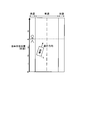
- FIG. 12 is a diagram illustrating an example of detection of a dangerous direction.
- FIG. 13 is a diagram illustrating an example of a traffic scene.
- FIG. 14 is a diagram illustrating an example of a traffic scene.
- FIG. 15 is a diagram illustrating an example of a traffic scene.
- FIG. 16 is a diagram illustrating an example of a traffic scene.
- FIG. 17 is a diagram illustrating an example of a traffic scene.
- FIG. 1 is a block diagram illustrating an example of a configuration of a vehicle information transmission system according to the present embodiment.
- the vehicle 1 includes a display device 10 such as a light indicator, a camera 11, a vehicle speed sensor 12, a steering sensor 13, an accelerator sensor 14, a brake sensor 15, an ECU (electronic control unit) 16, and a lighting control unit. 17 are provided.
- the ECU 16 includes a danger direction detection unit 16a, an operation state acquisition unit 16b, an avoidance behavior detection unit 16c, an in-avoidance danger possibility detection part 16d, and a post-avoidance danger possibility detection part 16e.
- the display device 10 is a device for transmitting effective avoidance action for a dangerous object so that the driver does not feel troublesome.
- the display device 10 includes a liquid crystal panel or a plurality of full-color LEDs (light-emitting diodes). 10a.
- the display screen 10a includes a safety area frame 10b indicating that the possibility that the vehicle 1 collides with a nearby dangerous object is relatively low, and the host vehicle indicating the state (safety status) of the vehicle 1.
- the status display graphic 10c is displayed.
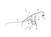
- FIG. 2 is a diagram illustrating an example of the mounting position of the display device 10.
- reference numeral 20 denotes a windshield
- reference numeral 21 denotes a hood
- reference numeral 22 denotes an instrument panel
- reference numeral 23 denotes a meter panel
- reference numeral 24 denotes a steering wheel (handle)
- reference numeral 30 Is the driver's eye point
- reference numeral 31 is the driver's line of sight (central view) during normal driving
- reference numeral 32 is the driver's line of sight (periphery) for viewing the display device 10.
- the display device 10 is installed on the instrument panel 22, but the range of the driver's peripheral vision (for example, the lowest layer of the driver's peripheral vision (for example, the line indicated by reference numeral 31) is provided so that the driver does not feel troublesome. And the depression angle ⁇ is 5 degrees or less, etc.), and the driver can recognize the display device 10. Moreover, the display apparatus 10 is installed in the position of the driver
- the eye point 30 is a point 635 (mm) above the seating reference point, which is the hip joint point of the human model when the model is seated on the seat according to ISO 6549-1980 ( Notification [2005.11.09] that stipulates the details of the safety standards for road transport vehicles disclosed in the homepage address "http://www.mlit.go.jp/jidosha/kijiyun/saimokubetten/saibet_081_00.pdf" See Appendix 81 (Technical Standards for Direct Direct Confirmation Mirrors) ”).
- the camera 11 may be in a state of the environment outside the vehicle 1 (specifically, there may be a dangerous object (for example, a pedestrian, bicycle, or other vehicle) that causes a contact accident with the vehicle 1.
- the state of the periphery of the front of the vehicle 1 including the vicinity of the course of the vehicle 1 having For example, a radar may be used instead of the camera.
- the vehicle speed sensor 12 detects the vehicle speed of the vehicle 1.
- the steering sensor 13 detects the steering direction of the handle 24 of the vehicle 1.
- the accelerator sensor 14 detects ON / OFF of the accelerator pedal of the vehicle 1.
- the brake sensor 15 detects ON / OFF of the brake pedal of the vehicle 1.
- the dangerous direction detection unit 16a detects the presence / absence of a dangerous object and the presence direction (danger direction) of the dangerous object based on the position or traveling direction of the vehicle 1 from the video obtained by the camera 11. Specifically, when a dangerous target exists, the dangerous direction detection unit 16a detects whether the dangerous target is present on the left, front, or right with respect to the position or traveling direction of the vehicle 1.
- the operation status acquisition unit 16b includes information on the operation status of a safe driving support device (for example, an engine failure warning light, a brake hydraulic pressure warning light, or a skid prevention system operation display) other than the display device 10 mounted on the vehicle 1. get.
- a safe driving support device for example, an engine failure warning light, a brake hydraulic pressure warning light, or a skid prevention system operation display
- the avoidance behavior detection unit 16c drives the dangerous object detected by the danger direction detection unit 16a based on the detection result of the steering sensor 13, the detection result of the accelerator sensor 14, the detection result of the brake sensor 15, and the like. It is detected (determined) whether the person has taken an appropriate (recommended) avoidance action. Specifically, when the danger direction detected by the danger direction detection unit 16a is left or right, it is recommended as the avoidance action to move the vehicle 1 away from the detected danger object.
- the unit 16c is configured such that the handle 24 is opposite to the danger direction (specifically, the danger direction is within a predetermined time (for example, 2 seconds) after the display state of the vehicle state display graphic 10c is changed to the danger information display state.
- the avoidance action detection unit 16c Detects whether the accelerator is turned off or the brake is turned on within a predetermined time (for example, 2 seconds) after the display state of the vehicle state display graphic 10c becomes the danger information display state.
- the types of devices operated to take the avoidance action specifically, the steering wheel, the accelerator pedal, and the brake pedal
- the operation method thereof specifically, the direction opposite to the danger direction
- Steering of the steering wheel, accelerator pedal OFF, and brake pedal ON are specified, and the operation amount of the equipment (specifically, the steering amount of the steering wheel, the return amount of the accelerator pedal, and the depression amount of the brake pedal) is not specified.
- the operation amount of the equipment specifically, the steering amount of the steering wheel, the return amount of the accelerator pedal, and the depression amount of the brake pedal.
- the avoiding danger possibility detecting unit 16d corresponds to the avoiding action detecting means of the present invention. Based on the image obtained by the camera 11, the avoiding danger possibility detection unit 16d is a vehicle in a forward range of the vehicle 1 (for example, a predetermined time (for example, 4 seconds) from the current position of the vehicle 1). Whether there is another dangerous object that is different from the dangerous object currently being avoided (avoided object) detected by the dangerous direction detection unit 16a and that may change to a danger in the future. Detect whether or not.
- the post-avoidance danger possibility detection unit 16e is based on the image obtained by the camera 11, and is a vehicle in a forward range of the vehicle 1 (for example, a predetermined time (for example, 3 seconds) from the current position of the vehicle 1). It is detected whether or not there is a danger object that may change to danger in the future (in the range up to the existence position of 1).
- the lighting control unit 17 corresponds to the reference mark display means and the danger display means of the present invention.
- the lighting control unit 17 detects the detection result in the danger direction detection unit 16a, the acquisition result in the operation state acquisition unit 16b, the detection result in the avoidance behavior detection unit 16c, the detection result in the avoidance danger possibility detection unit 16d, and the avoidance.
- the display state of the safety area frame 10b and the vehicle state display graphic 10c is controlled based on the detection result in the rear danger possibility detection unit 16e.
- the lighting control unit 17 may adjust the luminance of light by turning on / off a headlight or a conlight sensor. For example, the lighting control unit 17 may reduce the luminance of light at night.
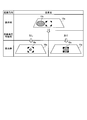
- FIG. 3 is a diagram illustrating an example of the display screen 10a in the initial state.
- the lighting control unit 17 displays the safe area frame 10b near the center of the display screen 10a.
- the lighting control part 17 displays the own vehicle state display figure 10c near the center of the safety area frame 10b.
- the display shape of the safety area frame 10b may be, for example, a shape capable of recognizing four sides of a quadrilateral other than the shape shown in FIG.
- the display shape of the safety area frame 10b may be a shape based on, for example, a polygon, a circle, or an ellipse other than the shape shown in FIG.
- the display color of the safety area frame 10b may be a color that does not make the driver feel bothersome and the display color of the vehicle state display graphic 10c is more conspicuous than the safety area frame 10b.
- the display shape of the vehicle state display graphic 10c may be, for example, a polygon or an ellipse other than the circle shown in FIG.
- the display area of the vehicle state display graphic 10c may be an area as small as shown in FIG. 3 that fits in the safety area frame 10b with sufficient margin in the initial state.
- the display color of the vehicle state display graphic 10c may be a green color in the initial state, and may be a red color in the danger information display state.
- FIG. 4 is a diagram showing a change example of the display state of the vehicle state display graphic 10c.
- the lighting control unit 17 displays the display state of the vehicle state display graphic 10c in order to convey the effective avoidance action without causing the driver to feel annoyance.
- the lighting control unit 17 changes the display position of the vehicle state display graphic 10c from the display position in the initial state.
- the display position is changed to the display position on the same side as the danger direction (specifically, the left side if the danger direction is left, the right side if the danger direction is right) and the outside of the safety area frame 10b.
- the lighting control unit 17 operates the danger direction from the display position of the vehicle state display graphic 10c from the initial display position.
- the display position is changed to an upper display position that can be easily recognized by a person.
- the lighting control unit 17 changes the display area of the vehicle state display graphic 10c from the initial display area into the safety area frame 10b.
- the display area is changed to a size as shown in FIG.
- the lighting control unit 17 changes the display color of the vehicle state display graphic 10c from the initial display color (for example, green color).
- the display color of the information display state for example, red color
- FIG. 5 is a diagram showing an example of a change in the display state of the vehicle state display graphic 10c.
- the display state of the vehicle state display graphic 10c is in the danger information display state
- the avoidance action detection unit 16c detects that the driver has taken an appropriate avoidance action
- the lighting control unit 17 The display state of the host vehicle state display graphic 10c is changed (transitioned), for example, stepwise or gradually from the danger information display state to the initial state (safety information display state).
- the display contents did not change even if the avoidance action was taken, so the driver's subjectivity that “because of the avoidance action was taken to be safe” and the display content that “there is a dangerous object”
- the driver may feel discomfort or annoyance.
- by eliminating this divergence it is possible to provide driving assistance that is pleasing to the driver and that matches the driver's feeling.
- FIG. 6 is a diagram showing an example of a change in the display state of the vehicle state display graphic 10c.
- the lighting control unit 17 changes the display state of the vehicle state display graphic 10c from the danger information display state to the danger information highlighted display state within a predetermined time (for example, 0.5 seconds). (Change finished) Specifically, the lighting control unit 17 changes (increases) the display area of the vehicle state display graphic 10c to a display area larger than the display area in the danger information display state.
- the lighting control unit 17 changes (deforms) the display shape of the vehicle state display graphic 10c to a display shape (for example, an ellipse) different from the display shape (for example, a circle) in the danger information display state.
- a display shape for example, an ellipse
- the driver cannot obtain a chance to correct the avoidance action.
- the driver can select a correct avoidance action.
- FIG. 7 is a diagram showing an example of a traffic scene.
- FIG. 8 is a diagram illustrating a change example of the display state of the own vehicle state display graphic 10c.
- the lighting control unit 17 changes the display state of the vehicle state display graphic 10c according to the detection result of the during-avoidance danger possibility detection unit 16d to the danger information highlight display state. To the best information display state. Specifically, the lighting control unit 17 changes the display position of the vehicle state display graphic 10c to the display position in the initial state.
- the lighting control unit 17 displays the display area of the vehicle state display graphic 10c smaller than the display area in the danger information highlight display state when another danger target is detected by the avoiding danger possibility detection unit 16d.
- the display area for example, the display area in the danger information display state
- the display area is smaller than the small display area. It is changed (reduced) to (for example, the display area in the initial state).
- the display color of the own vehicle state display graphic 10c in the best information display state is that the vehicle 1 does not pass the dangerous object detected by the dangerous direction detection unit 16a, and the driver avoids the dangerous object.
- the display color for example, a red color
- the danger information highlight display state that is, the danger information display state
- the avoidance action for a specific dangerous target may not be smoothly performed because it is affected by other targets other than the specific dangerous target in a traffic environment in which various targets are mixed.
- the cause when the avoidance action did not work could not be specified, even if the driver took the avoidance action, it may be determined that the avoidance action is not correct. Therefore, the driver sometimes felt uncomfortable.
- driving in which the driver is happy by telling that the driver's avoidance behavior was the best in the actual traffic environment where the avoidable behavior that can be taken is limited. Support can be provided.
- FIG. 9 is a diagram showing an example of a traffic scene.
- the lighting control unit 17 changes the display state of the host vehicle state display graphic 10c to the post-avoidance information display state (waiting time) according to the detection result of the post-avoidance danger possibility detection unit 16e.
- the timing is from the time when the vehicle 1 passes the side of the danger target (avoidance target) detected by the danger direction detection unit 16a.
- the danger target When the danger target is not detected by the post-avoidance danger possibility detection unit 16e, it is set at a time point exceeding 3 seconds (for example, 4 to 6 seconds), and from the time point when the vehicle 1 passes the side of the avoidance object. It is set to a time point within 3 seconds (for example, 1 to 3 seconds). And the lighting control part 17 changes the display state of the own vehicle state display figure 10c to the best information display state corresponding to the information display state after avoidance at the set timing.
- 3 seconds for example, 4 to 6 seconds
- the lighting control part 17 changes the display state of the own vehicle state display figure 10c to the best information display state corresponding to the information display state after avoidance at the set timing.
- the lighting control unit 17 turns off the vehicle state display graphic 10c. Thereby, the driver can quickly notice the situation of the safe driving support device other than the display device 10 having a high priority in maintaining the safe driving, and as a result, the driver can enter the safe state of the host vehicle. Transition can be done smoothly.
- FIG. 10 is a flowchart illustrating an example of main processing executed in the vehicle information transmission system according to the present embodiment.
- the safety area frame 10b and the vehicle state display graphic 10c in the initial state (safe state) are displayed in advance on the display screen 10a.
- Step S1 Measurement of the environment outside the vehicle
- the danger direction detection unit 16 a acquires, from the camera 11, an image around the front of the vehicle 1 including the vicinity of the course of the vehicle 1. In this description, it is assumed that the video shown in FIG. 11 has been acquired.
- Step S2 Dangerous Object / Direction Detection
- the danger direction detection unit 16a detects the danger target and the danger direction from the video acquired in step S1. In this description, it is assumed that the danger direction is detected to the left of the vehicle 1 as shown in FIG.
- Step S3 Determination of Display Execution
- the lighting control unit 17 confirms that the safe driving support device other than the display device 10 is in a normal state or not in a failure state based on the operation state acquired by the operation state acquisition unit 16b. In this description, it is assumed that the normal state has been confirmed.
- driving support by the display device 10 and driving support by another safe driving support device can be made compatible.
- Step S4 Display of danger information
- the lighting control unit 17 changes the display state of the vehicle state display graphic 10c to the danger information display state. Specifically, since the lighting control unit 17 detects that the danger direction is the left in step S2, the display position of the vehicle state display graphic 10c is set to the left of the display position in the initial state and the safety area frame 10b. Change to the display position outside of.
- the lighting control unit 17 changes the display area of the vehicle state display graphic 10c to a display area that is larger than the display area in the initial state and is large enough to fit within the safety region frame 10b without a gap.
- the lighting control unit 17 changes the display color of the host vehicle state display graphic 10c from the initial state green to the danger information display state red.
- the state of the environment outside the vehicle 1 at the time when the display state of the vehicle state display graphic 10c changes to the danger information display state is the state shown in FIG.
- the danger target detected in step S2 is present at the position where the vehicle 1 is present 4 seconds after the display state of the host vehicle state display graphic 10c changes to the danger information display state.
- Step S5 Emphasis on Display of Danger Information
- the avoidance behavior detection unit 16c determines that the driver is appropriate for the danger target detected in step S2 based on the detection result of the steering sensor 13, the detection result of the accelerator sensor 14, and the detection result of the brake sensor 15. Whether or not an avoidance action has been taken is detected within a time range within 2 seconds from when the display state of the vehicle state display graphic 10c changes to the danger information display state. In this description, it is assumed that it was not detected in step S5 that the driver took an appropriate avoidance action.
- the lighting control part 17 changes the display state of the host vehicle state display graphic 10c to the danger information highlight display state. Finish changing within seconds. Specifically, the lighting control unit 17 changes (increases) the display area of the vehicle state display graphic 10c to a display area larger than the display area in the danger information display state. In addition, the lighting control unit 17 changes (deforms) the display shape of the host vehicle state display graphic 10c to an ellipse having a display shape different from the circle that is the display shape in the danger information display state. By the process of step S4, the necessity of avoidance behavior can be communicated to the driver.
- the state of the environment outside the vehicle 1 at the time when the display state of the host vehicle state display graphic 10c is changed to the danger information highlight display state is the state shown in FIG. Specifically, the position of the vehicle 1 is moved from the position at which the display state of the vehicle state display graphic 10c is changed to the danger information display state to the position after 2 seconds from the change. And Further, it is assumed that the danger target detected in step S2 exists at the position where the vehicle 1 is present 2 seconds after the display state of the host vehicle state display graphic 10c changes to the danger information emphasis display state.
- Step S6 Detection of Avoidance Behavior
- the avoidance behavior detection unit 16c Based on the detection result of the steering sensor 13, the avoidance behavior detection unit 16c detects that the driver has taken an appropriate avoidance behavior with respect to the dangerous object detected in step S2. Specifically, the avoidance action detection unit 16c detects that the steering wheel has been turned to the right opposite to the left, which is a dangerous direction.
- the state of the outside environment of the vehicle 1 at the time when the avoidance behavior detection unit 16c detects the avoidance behavior is the state shown in FIG.
- the location of the vehicle 1 is from the location when the display state of the host vehicle state display graphic 10c is changed to the danger information emphasis display state to the location after 0.5 seconds after the change. It has been moved.
- the danger target detected in step S2 is present at the position where the vehicle 1 is present 1.5 seconds after the display state of the host vehicle state display graphic 10c changes to the danger information emphasis display state.
- Step S7 Determination of Avoidance State
- the during-avoidance danger possibility detection unit 16 d is detected in step S ⁇ b> 2 in the forward range from the current position of the vehicle 1 to the position where the vehicle 1 is present 4 seconds after the current time. It is detected whether there is another dangerous object that is different from the dangerous object (avoidance object) and may change into a danger in the future. In this description, it is assumed that another dangerous object has not been detected in step S7.
- the lighting control unit 17 detects that the driver has taken an appropriate avoidance action in step S6, and another dangerous object has not been detected by the during-avoidance danger possibility detection unit 16d.
- the display state of 10c is changed to the best information display state. Specifically, the lighting control unit 17 erases the vehicle state display graphic 10c in the danger information emphasis display state from the display screen 10a. In addition, the lighting control unit 17 displays a red host vehicle state display graphic 10c in the initial state display position and in the initial state display area and in the danger information display state.
- the state of the environment outside the vehicle 1 at the time when the display state of the vehicle state display graphic 10c changes to the best information display state is the state shown in FIG.
- the position of the vehicle 1 is a little over 0.5 seconds (0.6 to 0.8 seconds) from the position when the display state of the host vehicle state display graphic 10c is changed to the danger information emphasis display state.
- the danger target detected in step S2 is the vehicle 1 that is less than 1.5 seconds (1.2 to 1.4 seconds) after the display state of the vehicle state display graphic 10c changes to the best information display state. It exists in the existence position of.
- Step S8 Control of state display time after avoidance
- the post-avoidance danger possibility detection unit 16e changes from the current position of the vehicle 1 to a forward range from the current position to the position where the vehicle 1 exists three seconds later. Detects whether there is a potentially dangerous object. In this description, it is assumed that no dangerous object has been detected in step S8.
- the lighting control unit 17 does not detect the danger target by the post-avoidance danger possibility detection unit 16e, and therefore, 2.5 seconds from when the vehicle 1 passes the side of the danger target (avoidance target) detected in step S2.
- the later time is set as a timing for changing the display state of the vehicle state display graphic 10c to the post-avoidance information display state.
- Step S9 Display of the state after avoidance
- the lighting control unit 17 changes the display state of the vehicle state display graphic 10c to the initial state corresponding to the post-avoidance information display state when the dangerous object is not detected in step S8 at the timing set in step S8 ( Transition). Specifically, the lighting control unit 17 changes the display color of the vehicle state display graphic 10c to the initial green color.
- the state of the environment outside the vehicle 1 at the time when the display state of the vehicle state display graphic 10c changes to the post-avoidance information display state is the state shown in FIG.
- the vehicle 1 is located on the side of the dangerous object (avoidance object) detected in step S2 from the existing position when the display state of the vehicle state display graphic 10c is changed to the best information display state. It is assumed that the vehicle has passed through and moved to an existing position 2.5 seconds after the passage.
- the lighting control unit 17 displays the safety region frame 10b near the center of the display screen 10a and the vehicle state display graphic 10c in the initial state near the center of the safety region frame 10b. . Then, the lighting control unit 17 changes the display state of the vehicle state display graphic 10c from the initial state to the danger information display state, thereby displaying the presence / absence of the danger target and the danger direction at a relative position with respect to the safety area frame 10b. Thereby, the information regarding the danger around the own vehicle can be transmitted so that the driver can easily understand intuitively. In addition, effective danger avoidance behavior can be transmitted without causing the driver to feel troublesome.
- the lighting control unit 17 sets the display position of the vehicle state display graphic 10c to the danger information display state. By changing from the display position to the display position in the initial state, it is displayed at the display position of the safe area frame 10b that the appropriate avoidance action has been taken. Thereby, driving assistance reflecting the driver's intention can be provided.
- the lighting control unit 17 displays the display state of the vehicle state display graphic 10c as the danger information.
- the presence / absence of the danger object and the danger direction display currently displayed are emphasized. Thereby, the necessity of avoidance action can be told to a driver.
- the lighting control unit 17 detects another dangerous object different from the dangerous object.
- the safety area indicates that an appropriate avoidance action has been taken by changing the display area of the vehicle state display graphic 10c to be displayed at the initial display position between the case and the case where the other dangerous object is not detected. It is displayed at the display position of the frame 10b. As a result, it is possible to tell that the best avoidance action is being performed.
- the vehicle information transmission device is useful in the automobile manufacturing industry, and is particularly suitable for information transmission to a driver.
Landscapes
- Engineering & Computer Science (AREA)
- Mechanical Engineering (AREA)
- Chemical & Material Sciences (AREA)
- Combustion & Propulsion (AREA)
- Transportation (AREA)
- Physics & Mathematics (AREA)
- General Physics & Mathematics (AREA)
- Human Computer Interaction (AREA)
- Traffic Control Systems (AREA)
- Instrument Panels (AREA)
Abstract
Description
本実施形態にかかる車両用情報伝達システムの構成の一例について、図1から図9を参照して説明する。図1は、本実施形態にかかる車両用情報伝達システムの構成の一例を示すブロック図である。
本実施形態にかかる車両用情報伝達システムで実行されるメイン処理の一例について、図10から図17を参照して説明する。図10は、本実施形態にかかる車両用情報伝達システムで実行されるメイン処理の一例を示すフローチャートである。なお、本説明では、表示画面10aに安全領域枠10bと初期状態(安全状態)の自車状態表示図形10cが予め表示されているものとする。
危険方向検出部16aは、カメラ11から、車両1の進路付近を含む車両1の前方周辺の映像を取得する。本説明では、図11に示す映像が取得されたものとする。
危険方向検出部16aは、ステップS1で取得された映像から、危険対象および危険方向を検出する。本説明では、図12に示すように、危険方向が車両1の左であることが検出されたものとする。
点灯制御部17は、動作状況取得部16bで取得された動作状況に基づいて、表示装置10以外の安全運転支援装置が正常状態または故障していない状態であること確認する。本説明では、正常状態であることが確認されたものとする。ステップS3の処理により、表示装置10による運転支援と他の安全運転支援装置による運転支援を両立させることができる。
点灯制御部17は、ステップS2で危険方向が検出されたので、自車状態表示図形10cの表示状態を危険情報表示状態に変化させる。具体的には、点灯制御部17は、ステップS2で危険方向が左であると検出されたので、自車状態表示図形10cの表示位置を、初期状態の表示位置の左側で且つ安全領域枠10bの外側の表示位置に変化させる。また、点灯制御部17は、自車状態表示図形10cの表示面積を、初期状態の表示面積より大きく且つ安全領域枠10b内にその全体が隙間なく収まる程度の大きさの表示面積に変化させる。また、点灯制御部17は、自車状態表示図形10cの表示色を、初期状態の緑色から、危険情報表示状態の赤色に変化させる。ステップS4の処理により、有効な危険回避行動を、運転者に煩わしさを覚えさせずに伝えることができる。
回避行動検出部16cは、操舵センサ13での検出結果、アクセルセンサ14での検出結果およびブレーキセンサ15での検出結果に基づいて、ステップS2で検出された危険対象に対して運転者が適切な回避行動を取ったか否かを、自車状態表示図形10cの表示状態が危険情報表示状態に変化した時から2秒以内の時間範囲で検出する。本説明では、ステップS5において、運転者が適切な回避行動を取ったことが検出されなかったものとする。
回避行動検出部16cは、操舵センサ13での検出結果に基づいて、ステップS2で検出された危険対象に対して運転者が適切な回避行動を取ったことを検出する。具体的には、回避行動検出部16cは、危険方向である左とは逆の右にハンドルが切られたことを検出する。
回避中危険可能性検出部16dは、カメラ11で得られた映像に基づいて、車両1の現在位置から、現時点から4秒後の車両1の存在位置までの前方範囲に、ステップS2で検出された危険対象(回避対象)とは異なり且つ今後危険に変化する可能性のある別の危険対象が存在するか否かを検出する。本説明では、ステップS7において、別の危険対象が検出されなかったものとする。
回避後危険可能性検出部16eは、カメラ11で得られた映像に基づいて、車両1の現在位置から、現時点から3秒後の車両1の存在位置までの前方範囲に、今後危険に変化する可能性のある危険対象が存在するか否かを検出する。本説明では、ステップS8において、危険対象が検出されなかったものとする。
点灯制御部17は、ステップS8で設定したタイミングで、自車状態表示図形10cの表示状態を、ステップS8で危険対象が検出されなかった場合の回避後情報表示状態に相当する初期状態に変化(遷移)させる。具体的には、点灯制御部17は、自車状態表示図形10cの表示色を初期状態の緑色に変化させる。
以上、本実施形態によれば、点灯制御部17は、表示画面10aの中心付近に安全領域枠10bを表示すると共に安全領域枠10bの中心付近に初期状態の自車状態表示図形10cを表示する。そして、点灯制御部17は、自車状態表示図形10cの表示状態を初期状態から危険情報表示状態に変化させることで、危険対象の有無および危険方向を安全領域枠10bに対する相対位置で表示する。これにより、自車両周辺の危険に関する情報を、運転者が直感的に分かり易いように伝達することができる。また、有効な危険回避行動を、運転者に煩わしさを覚えさせずに伝えることができる。
11 カメラ
12 車速センサ
13 操舵センサ
14 アクセルセンサ
15 ブレーキセンサ
16 ECU
16a 危険方向検出部
16b 動作状況取得部
16c 回避行動検出部
16d 回避中危険可能性検出部
16e 回避後危険可能性検出部
17 点灯制御部
Claims (5)
- 安全状態であることを示す基準となる基準目印を表示する基準目印表示手段と、
自車両に対する危険性の有無を前記基準目印に対する相対位置で表示する危険表示手段と
を備えたことを特徴とする車両用情報伝達装置。 - 請求項1に記載の車両用情報伝達装置において、
前記危険表示手段は、前記危険性が有る場合、前記危険性が有る方向を前記基準目印に対する相対位置で表示すること、
を特徴とする車両用情報伝達装置。 - 請求項1または2に記載の車両用情報伝達装置において、
前記危険性が有る場合に、前記危険性に対応する回避行動の有無を検出する回避行動検出手段をさらに備え、
前記危険表示手段は、前記回避行動検出手段で前記回避行動が有ると検出された場合、前記回避行動が有ることを前記基準目印の表示位置に表示すること、
を特徴とする車両用情報伝達装置。 - 請求項1から3のいずれか1つに記載の車両用情報伝達装置において、
前記危険表示手段は、前記回避行動検出手段で前記回避行動が無いと検出された場合、前記危険性が有ることの表示を強調させること、
を特徴とする車両用情報伝達装置。 - 請求項3に記載の車両用情報伝達装置において、
前記危険表示手段は、前記回避行動が有ることの表示を、前記危険性とは異なる別の危険性の有無に応じて異ならせること、
を特徴とする車両用情報伝達装置。
Priority Applications (5)
| Application Number | Priority Date | Filing Date | Title |
|---|---|---|---|
| JP2013549007A JP5817843B2 (ja) | 2011-12-14 | 2011-12-14 | 車両用情報伝達装置 |
| EP11877344.9A EP2792529B1 (en) | 2011-12-14 | 2011-12-14 | Vehicle information transmitting device |
| PCT/JP2011/078963 WO2013088535A1 (ja) | 2011-12-14 | 2011-12-14 | 車両用情報伝達装置 |
| CN201180075523.7A CN103987559B (zh) | 2011-12-14 | 2011-12-14 | 车辆用信息传递装置 |
| US14/365,381 US9583002B2 (en) | 2011-12-14 | 2011-12-14 | Vehicle information transmitting device |
Applications Claiming Priority (1)
| Application Number | Priority Date | Filing Date | Title |
|---|---|---|---|
| PCT/JP2011/078963 WO2013088535A1 (ja) | 2011-12-14 | 2011-12-14 | 車両用情報伝達装置 |
Publications (1)
| Publication Number | Publication Date |
|---|---|
| WO2013088535A1 true WO2013088535A1 (ja) | 2013-06-20 |
Family
ID=48612021
Family Applications (1)
| Application Number | Title | Priority Date | Filing Date |
|---|---|---|---|
| PCT/JP2011/078963 WO2013088535A1 (ja) | 2011-12-14 | 2011-12-14 | 車両用情報伝達装置 |
Country Status (5)
| Country | Link |
|---|---|
| US (1) | US9583002B2 (ja) |
| EP (1) | EP2792529B1 (ja) |
| JP (1) | JP5817843B2 (ja) |
| CN (1) | CN103987559B (ja) |
| WO (1) | WO2013088535A1 (ja) |
Cited By (3)
| Publication number | Priority date | Publication date | Assignee | Title |
|---|---|---|---|---|
| WO2015001815A1 (ja) * | 2013-07-05 | 2015-01-08 | クラリオン株式会社 | 運転支援装置 |
| JP2015161651A (ja) * | 2014-02-28 | 2015-09-07 | アイシン・エィ・ダブリュ株式会社 | 運転支援システム、運転支援方法、及び運転支援プログラム |
| JP2018181061A (ja) * | 2017-04-17 | 2018-11-15 | 株式会社デンソー | 運転支援装置 |
Families Citing this family (11)
| Publication number | Priority date | Publication date | Assignee | Title |
|---|---|---|---|---|
| DE102013206346A1 (de) * | 2013-04-11 | 2014-10-16 | Zf Friedrichshafen Ag | Sensorvorrichtung und Verfahren zum Bestimmen eines Lenkwinkels eines Fahrzeugs und Fahrerassistenzsystem für ein Fahrzeug |
| DE102013206345A1 (de) * | 2013-04-11 | 2014-10-16 | Zf Friedrichshafen Ag | Anzeigevorrichtung und Verfahren zum Anzeigen von Daten und Fahrerassistenzsystem für ein Fahrzeug |
| JP6123761B2 (ja) * | 2014-09-05 | 2017-05-10 | トヨタ自動車株式会社 | 車両用表示装置 |
| JP6515773B2 (ja) * | 2015-10-09 | 2019-05-22 | 株式会社デンソー | 情報処理装置 |
| JP6613795B2 (ja) * | 2015-10-16 | 2019-12-04 | 株式会社デンソー | 表示制御装置および車両制御装置 |
| CN107298021B (zh) * | 2016-04-15 | 2022-03-08 | 松下电器(美国)知识产权公司 | 信息提示控制装置、自动驾驶车及其驾驶辅助系统 |
| CN106772383B (zh) * | 2016-12-31 | 2019-03-22 | 智车优行科技(北京)有限公司 | 车辆周围物体的检测呈现方法、装置和系统、车辆 |
| US20190270331A1 (en) * | 2018-03-01 | 2019-09-05 | Kabushiki Kaisha Toshiba | Quota management apparatus, quota management method and non-temporary recording medium |
| JP6954198B2 (ja) * | 2018-03-23 | 2021-10-27 | 株式会社Jvcケンウッド | 端末装置、グループ通信システム、及びグループ通信方法 |
| KR20210041224A (ko) * | 2019-10-07 | 2021-04-15 | 현대자동차주식회사 | 자동차 및 그를 위한 주변 정보 출력 방법 |
| JP2023049833A (ja) * | 2021-09-29 | 2023-04-10 | 本田技研工業株式会社 | 注意喚起システム、及び制御用プログラム |
Citations (8)
| Publication number | Priority date | Publication date | Assignee | Title |
|---|---|---|---|---|
| JPH05124459A (ja) * | 1991-10-31 | 1993-05-21 | Nippon Seiki Co Ltd | 走行情報表示装置 |
| JP2003291688A (ja) * | 2002-04-03 | 2003-10-15 | Denso Corp | 表示方法、運転支援装置、プログラム |
| JP2006171950A (ja) | 2004-12-14 | 2006-06-29 | Denso Corp | ヘッドアップディスプレイの表示制御装置およびプログラム |
| JP2006224700A (ja) | 2005-02-15 | 2006-08-31 | Denso Corp | 車両用死角監視装置及び車両用運転支援システム |
| JP2006284458A (ja) * | 2005-04-01 | 2006-10-19 | Denso Corp | 運転支援情報表示システム |
| JP2009120014A (ja) * | 2007-11-14 | 2009-06-04 | Mazda Motor Corp | 車両用表示装置 |
| JP2010247656A (ja) * | 2009-04-15 | 2010-11-04 | Toyota Motor Corp | 運転支援システムおよび運転支援方法 |
| JP2011008769A (ja) | 2009-05-29 | 2011-01-13 | Denso Corp | 運転診断装置 |
Family Cites Families (10)
| Publication number | Priority date | Publication date | Assignee | Title |
|---|---|---|---|---|
| DE4317831C1 (de) * | 1993-05-28 | 1994-07-07 | Daimler Benz Ag | Display zur Anzeige der Gefahrenträchtigkeit der momentanen Fahrsituation eines Kraftfahrzeugs |
| FR2715243B1 (fr) * | 1994-01-18 | 1996-02-09 | Renault | Dispositif de visualisation d'informations pour conducteur routier. |
| US20040046647A1 (en) * | 2000-11-21 | 2004-03-11 | Reeves Michael J. | Vehicle safety sensor system |
| JP2006127055A (ja) | 2004-10-27 | 2006-05-18 | Denso Corp | 車両用情報提示装置 |
| JP4887980B2 (ja) | 2005-11-09 | 2012-02-29 | 日産自動車株式会社 | 車両用運転操作補助装置および車両用運転操作補助装置を備えた車両 |
| DE102005057636B4 (de) * | 2005-12-02 | 2022-08-11 | Volkswagen Ag | Kraftfahrzeug |
| DE102006011481A1 (de) * | 2006-03-13 | 2007-09-20 | Robert Bosch Gmbh | Verfahren und Vorrichtung zum Unterstützen eines Führens eines Fahrzeugs |
| DE102006049249A1 (de) * | 2006-10-19 | 2008-04-30 | Robert Bosch Gmbh | Verfahren zum Informieren des Fahrers eines Kraftfahrzeugs |
| DE102008036009B4 (de) * | 2008-03-28 | 2018-03-22 | Volkswagen Ag | Verfahren zum Kollisionsschutz eines Kraftfahrzeugs und Parkhausassistent |
| US20120123613A1 (en) * | 2009-07-17 | 2012-05-17 | Panasonic Corporation | Driving support device, driving support method, and program |
-
2011
- 2011-12-14 JP JP2013549007A patent/JP5817843B2/ja active Active
- 2011-12-14 US US14/365,381 patent/US9583002B2/en active Active
- 2011-12-14 EP EP11877344.9A patent/EP2792529B1/en active Active
- 2011-12-14 CN CN201180075523.7A patent/CN103987559B/zh active Active
- 2011-12-14 WO PCT/JP2011/078963 patent/WO2013088535A1/ja active Application Filing
Patent Citations (8)
| Publication number | Priority date | Publication date | Assignee | Title |
|---|---|---|---|---|
| JPH05124459A (ja) * | 1991-10-31 | 1993-05-21 | Nippon Seiki Co Ltd | 走行情報表示装置 |
| JP2003291688A (ja) * | 2002-04-03 | 2003-10-15 | Denso Corp | 表示方法、運転支援装置、プログラム |
| JP2006171950A (ja) | 2004-12-14 | 2006-06-29 | Denso Corp | ヘッドアップディスプレイの表示制御装置およびプログラム |
| JP2006224700A (ja) | 2005-02-15 | 2006-08-31 | Denso Corp | 車両用死角監視装置及び車両用運転支援システム |
| JP2006284458A (ja) * | 2005-04-01 | 2006-10-19 | Denso Corp | 運転支援情報表示システム |
| JP2009120014A (ja) * | 2007-11-14 | 2009-06-04 | Mazda Motor Corp | 車両用表示装置 |
| JP2010247656A (ja) * | 2009-04-15 | 2010-11-04 | Toyota Motor Corp | 運転支援システムおよび運転支援方法 |
| JP2011008769A (ja) | 2009-05-29 | 2011-01-13 | Denso Corp | 運転診断装置 |
Non-Patent Citations (1)
| Title |
|---|
| See also references of EP2792529A4 |
Cited By (7)
| Publication number | Priority date | Publication date | Assignee | Title |
|---|---|---|---|---|
| WO2015001815A1 (ja) * | 2013-07-05 | 2015-01-08 | クラリオン株式会社 | 運転支援装置 |
| JP6051307B2 (ja) * | 2013-07-05 | 2016-12-27 | クラリオン株式会社 | 運転支援装置 |
| JPWO2015001815A1 (ja) * | 2013-07-05 | 2017-02-23 | クラリオン株式会社 | 運転支援装置 |
| US9827907B2 (en) | 2013-07-05 | 2017-11-28 | Clarion Co., Ltd. | Drive assist device |
| JP2015161651A (ja) * | 2014-02-28 | 2015-09-07 | アイシン・エィ・ダブリュ株式会社 | 運転支援システム、運転支援方法、及び運転支援プログラム |
| JP2018181061A (ja) * | 2017-04-17 | 2018-11-15 | 株式会社デンソー | 運転支援装置 |
| JP7039855B2 (ja) | 2017-04-17 | 2022-03-23 | 株式会社デンソー | 運転支援装置 |
Also Published As
| Publication number | Publication date |
|---|---|
| US20150002285A1 (en) | 2015-01-01 |
| CN103987559A (zh) | 2014-08-13 |
| JP5817843B2 (ja) | 2015-11-18 |
| US9583002B2 (en) | 2017-02-28 |
| CN103987559B (zh) | 2016-11-16 |
| JPWO2013088535A1 (ja) | 2015-04-27 |
| EP2792529A1 (en) | 2014-10-22 |
| EP2792529A4 (en) | 2016-06-29 |
| EP2792529B1 (en) | 2019-10-16 |
Similar Documents
| Publication | Publication Date | Title |
|---|---|---|
| JP5817843B2 (ja) | 車両用情報伝達装置 | |
| JP6699646B2 (ja) | 車両用表示制御装置 | |
| JP4941760B2 (ja) | 車両周辺監視装置 | |
| US9649936B2 (en) | In-vehicle device, control method of in-vehicle device, and computer-readable storage medium | |
| EP2068189B1 (en) | Head-up display device for vehicle | |
| US11325471B2 (en) | Method for displaying the course of a safety zone in front of a transportation vehicle or an object by a display unit, device for carrying out the method, and transportation vehicle and computer program | |
| EP3305597B1 (en) | Vehicle driving assist system | |
| US20100201508A1 (en) | Cross traffic alert system for a vehicle, and related alert display method | |
| US11021103B2 (en) | Method for enriching a field of view of a driver of a transportation vehicle with additional information, device for use in an observer transportation vehicle, device for use in an object, and transportation vehicle | |
| JP4946661B2 (ja) | 車両用警報表示装置 | |
| JP2004535971A (ja) | ヘッドアップディスプレイシステム及び方法 | |
| EP2894620B1 (en) | Vehicle information display device and vehicle information display method | |
| JP2008230558A (ja) | 車両周辺監視装置 | |
| KR20170000363A (ko) | 차량, 특히 상용 차량을 위한 디스플레이 시스템 | |
| JP2009269551A (ja) | 車両用表示装置 | |
| WO2020003750A1 (ja) | 車両用表示制御装置、車両用表示制御方法、及び制御プログラム | |
| JP6338626B2 (ja) | 車両の表示装置 | |
| JP2021172097A (ja) | 車両制御システム | |
| JP7155650B2 (ja) | 周辺監視装置 | |
| KR20170108720A (ko) | 차량의 장애물 감시 장치 및 그 제어 방법 | |
| US20220258756A1 (en) | Apparatus and method for providing autonomous driving information | |
| JP6424775B2 (ja) | 情報表示装置 | |
| JP4900146B2 (ja) | 障害物検知装置 | |
| EP1918896B1 (en) | Improved vehicle driving assistance system for keeping/changing lanes and associated operating method | |
| JP7275985B2 (ja) | 表示制御装置 |
Legal Events
| Date | Code | Title | Description |
|---|---|---|---|
| 121 | Ep: the epo has been informed by wipo that ep was designated in this application |
Ref document number: 11877344 Country of ref document: EP Kind code of ref document: A1 |
|
| ENP | Entry into the national phase |
Ref document number: 2013549007 Country of ref document: JP Kind code of ref document: A |
|
| WWE | Wipo information: entry into national phase |
Ref document number: 14365381 Country of ref document: US Ref document number: 2011877344 Country of ref document: EP |
|
| NENP | Non-entry into the national phase |
Ref country code: DE |