WO2013051654A1 - 内燃機関用点火コイル - Google Patents
内燃機関用点火コイル Download PDFInfo
- Publication number
- WO2013051654A1 WO2013051654A1 PCT/JP2012/075819 JP2012075819W WO2013051654A1 WO 2013051654 A1 WO2013051654 A1 WO 2013051654A1 JP 2012075819 W JP2012075819 W JP 2012075819W WO 2013051654 A1 WO2013051654 A1 WO 2013051654A1
- Authority
- WO
- WIPO (PCT)
- Prior art keywords
- slit
- coil
- internal combustion
- combustion engine
- ignition coil
- Prior art date
- Legal status (The legal status is an assumption and is not a legal conclusion. Google has not performed a legal analysis and makes no representation as to the accuracy of the status listed.)
- Ceased
Links
Images





Classifications
-
- H—ELECTRICITY
- H01—ELECTRIC ELEMENTS
- H01F—MAGNETS; INDUCTANCES; TRANSFORMERS; SELECTION OF MATERIALS FOR THEIR MAGNETIC PROPERTIES
- H01F5/00—Coils
-
- F—MECHANICAL ENGINEERING; LIGHTING; HEATING; WEAPONS; BLASTING
- F02—COMBUSTION ENGINES; HOT-GAS OR COMBUSTION-PRODUCT ENGINE PLANTS
- F02P—IGNITION, OTHER THAN COMPRESSION IGNITION, FOR INTERNAL-COMBUSTION ENGINES; TESTING OF IGNITION TIMING IN COMPRESSION-IGNITION ENGINES
- F02P15/00—Electric spark ignition having characteristics not provided for in, or of interest apart from, groups F02P1/00 - F02P13/00 and combined with layout of ignition circuits
-
- H—ELECTRICITY
- H01—ELECTRIC ELEMENTS
- H01F—MAGNETS; INDUCTANCES; TRANSFORMERS; SELECTION OF MATERIALS FOR THEIR MAGNETIC PROPERTIES
- H01F38/00—Adaptations of transformers or inductances for specific applications or functions
- H01F38/12—Ignition, e.g. for IC engines
-
- H—ELECTRICITY
- H01—ELECTRIC ELEMENTS
- H01F—MAGNETS; INDUCTANCES; TRANSFORMERS; SELECTION OF MATERIALS FOR THEIR MAGNETIC PROPERTIES
- H01F5/00—Coils
- H01F5/04—Arrangements of electric connections to coils, e.g. leads
-
- F—MECHANICAL ENGINEERING; LIGHTING; HEATING; WEAPONS; BLASTING
- F02—COMBUSTION ENGINES; HOT-GAS OR COMBUSTION-PRODUCT ENGINE PLANTS
- F02P—IGNITION, OTHER THAN COMPRESSION IGNITION, FOR INTERNAL-COMBUSTION ENGINES; TESTING OF IGNITION TIMING IN COMPRESSION-IGNITION ENGINES
- F02P13/00—Sparking plugs structurally combined with other parts of internal-combustion engines
-
- F—MECHANICAL ENGINEERING; LIGHTING; HEATING; WEAPONS; BLASTING
- F02—COMBUSTION ENGINES; HOT-GAS OR COMBUSTION-PRODUCT ENGINE PLANTS
- F02P—IGNITION, OTHER THAN COMPRESSION IGNITION, FOR INTERNAL-COMBUSTION ENGINES; TESTING OF IGNITION TIMING IN COMPRESSION-IGNITION ENGINES
- F02P3/00—Other installations
- F02P3/02—Other installations having inductive energy storage, e.g. arrangements of induction coils
-
- H—ELECTRICITY
- H01—ELECTRIC ELEMENTS
- H01F—MAGNETS; INDUCTANCES; TRANSFORMERS; SELECTION OF MATERIALS FOR THEIR MAGNETIC PROPERTIES
- H01F38/00—Adaptations of transformers or inductances for specific applications or functions
- H01F38/12—Ignition, e.g. for IC engines
- H01F2038/122—Ignition, e.g. for IC engines with rod-shaped core
-
- H—ELECTRICITY
- H01—ELECTRIC ELEMENTS
- H01T—SPARK GAPS; OVERVOLTAGE ARRESTERS USING SPARK GAPS; SPARKING PLUGS; CORONA DEVICES; GENERATING IONS TO BE INTRODUCED INTO NON-ENCLOSED GASES
- H01T13/00—Sparking plugs
- H01T13/40—Sparking plugs structurally combined with other devices
- H01T13/44—Sparking plugs structurally combined with other devices with transformers, e.g. for high-frequency ignition
Definitions
- the present invention relates to an ignition coil for an internal combustion engine used for generating a spark in a combustion chamber of the internal combustion engine.
- ignition coils are frequently used for ignition of internal combustion engines.
- a primary wire is wound around a primary spool to form a primary coil
- a secondary wire is wound around a secondary spool to form a secondary coil.
- the primary coil and the secondary coil are arranged in the case so as to be concentric to form a coil part, and the end of this coil part is fitted into the fitting hole of the connector case part in which the igniter is arranged. ing.
- the winding end of the primary wire is fixed to the terminal provided on the primary spool.
- the terminal provided in the primary spool and the terminal (conductor pin) provided in the connector case part are joined by performing processes such as resistance welding and fusing.
- the winding on the winding start side and the winding end side of the primary coil is fixed to a winding holding portion provided on the collar portion of the primary spool. And the winding of the winding start side and the winding end side is hold
- Patent Document 1 the primary coil is enlarged upward by drawing the primary wire upward along the axial direction of the primary spool. Further, in order to more easily assemble the ignition coil, it is necessary to further devise the terminal assembly structure.
- the present invention has been made in view of such a background, and provides an ignition coil for an internal combustion engine that can reduce the number of assembling steps and the number of parts and can be reduced in size.
- the ignition coil for an internal combustion engine has, as its basic configuration, a coil portion formed by arranging a primary coil and a secondary coil concentrically arranged on the inner and outer circumferences in a coil case, and the coil And a connector case portion having a connector portion for energizing and shutting off the primary coil.
- the primary coil is formed by winding a primary wire around the outer periphery of a primary spool made of resin.
- the connector case part is provided with a terminal made of a conductor arranged from the fitting hole to the connector part. In the terminal, an insertion slit is formed in the insertion portion arranged in the fitting hole toward the fitting direction of the coil portion and the connector case portion. The winding end of the primary coil is drawn substantially along the winding direction of the primary electric wire, and is inserted into the insertion slit in the fitting direction.
- the internal combustion engine ignition coil is characterized by the structure of the winding end of the primary coil and a terminal for conducting the coil.
- the terminal is provided in the connector case part, and the insertion slit of the terminal is formed in the insertion part of the coil part and the connector case part. Further, the winding end of the primary coil is drawn substantially along the winding direction of the primary electric wire.
- the winding end portion of the primary coil is inserted into the insertion slit of the insertion portion arranged in the fitting hole when the coil portion is fitted to the connector case portion.
- the winding end and the terminal are joined by pressure contact between the winding end and the terminal.
- the coil portion and the connector case portion can be fitted together, and at the same time, the winding end portion and the terminal can be pressed. Therefore, joining (pressure welding) between the winding end and the terminal can be performed very easily, and the number of assembling steps of the ignition coil can be reduced.
- the winding end of the primary coil is drawn almost along the winding direction of the primary wire. Therefore, it can prevent that a primary coil will become large in the axial direction of a primary spool. Therefore, the ignition coil can be reduced in size in the axial direction. Moreover, the ignition coil can be reduced in size by eliminating the connection between the terminals.
- the number of assembling steps and the number of parts can be reduced, and the size can be reduced.
- the connector portion can be a portion that is electrically connected to the outside of the ignition coil in the connector case portion. Further, when an igniter in which a switching circuit for energizing and interrupting the primary coil is disposed in the connector case portion, the connector portion can be provided around the igniter.
- the insertion portion has a pair of opposed plate portions whose strip plate-shaped plate surfaces face each other, and a distal end plate portion connected to the distal ends of the pair of opposed plate portions.
- the insertion slit may be formed continuously by dividing the tip plate portion up to the pair of opposed plate portions. In this case, the rigidity of the insertion part of the terminal can be easily ensured.
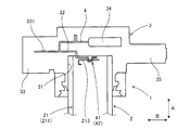
- Sectional drawing which shows the state which looked at the ignition coil for internal combustion engines concerning one Example from the front.
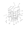
- Explanatory drawing which shows typically the arrangement
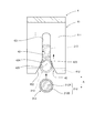
- Explanatory drawing which shows typically the arrangement
- the perspective view which shows the state which inserted the coil
- the perspective view which shows the state which fits the edge part of a coil part concerning the Example to the fitting hole of a connector case part.
- Explanatory drawing which shows the state by which the coil
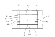
- Explanatory drawing which shows the insertion part of a terminal concerning an Example in the state seen from the downward direction.
- Explanatory drawing which expands and shows the periphery of the insertion slit in an opposing board part concerning an Example.
- Explanatory drawing which shows the insertion part of another terminal concerning an Example in the state seen from the downward direction.
- Explanatory drawing which shows the insertion part of another terminal concerning an Example in the state seen from the downward direction.
- Explanatory drawing which shows the insertion part of another terminal concerning an Example in the state seen from the downward direction.
- Explanatory drawing which shows the insertion part of another terminal concerning an Example in the state seen from the downward direction.
- FIG. 1 shows an internal combustion engine ignition coil 1 (hereinafter simply referred to as an ignition coil 1) in a cross-section viewed from the front.
- an ignition coil 1 hereinafter simply referred to as an ignition coil 1
- the ignition coil 1 includes a coil part 2 formed by arranging a primary coil 21 and a secondary coil 22 concentrically arranged on the inner and outer circumferences in a coil case 23, and an end of the coil part 2.
- the connector case part 3 which has the connector part 32 in which the fitting hole 31 which fits a part is formed, and energizes and interrupts
- FIG. 2 schematically shows the arrangement of the terminals 4 in the vicinity of the connector case section 3 as viewed from the front
- FIG. 3 schematically shows the arrangement of the terminals 4 in the vicinity of the connector case section 3 in a state as viewed from above.
- FIG. 4 shows a state where the winding end 213 of the primary coil 21 is inserted into the insertion slit 42 in the insertion part 41 of the terminal 4. 2 and 3, the shape of the terminal 4 near the connector portion 32 is schematically shown.
- the primary coil 21 is formed by winding a primary electric wire 212 around the outer periphery of a primary spool 211 made of resin.
- the connector case portion 3 is provided with a terminal 4 made of a conductor disposed from the fitting hole 31 to the connector portion 32.
- a terminal 4 made of a conductor disposed from the fitting hole 31 to the connector portion 32.
- an insertion slit 42 is formed in the insertion portion 41 disposed in the fitting hole 31 toward the fitting direction A between the coil portion 2 and the connector case portion 3.
- the winding end 213 of the primary coil 21 is drawn substantially along the winding direction B of the primary electric wire 212 and is inserted into the insertion slit 42 in the fitting direction A.
- the ignition coil 1 of the present example uses a coil portion 2 disposed in a plug hole of an engine as an internal combustion engine, and a connector case portion 3 disposed outside the plug hole. .
- the connector case portion 3 is fitted to the upper end portion in the axial direction of the coil portion 2, and a plug mounting portion 5 that is connected to the spark plug is provided at the lower end portion in the axial direction of the coil portion 2.
- a central core 24 made of a soft magnetic material is disposed on the inner peripheral side of the primary coil 21 and the secondary coil 22, and an outer peripheral core made of a soft magnetic material is provided on the outer peripheral side of the coil case 23. 25 is arranged.
- the secondary coil 22 is formed by winding a secondary wire thinner than the primary wire 212 around the outer circumference of the secondary spool 221 with a greater number of turns than the primary coil 21.
- the plug mounting portion 5 is electrically connected to the high voltage terminal 51 that conducts the high voltage winding end portion of the secondary coil 22 at the lower end portion in the axial direction of the primary spool 211 and the high voltage terminal 51.
- a coil spring 52 that conducts the electrode portion of the plug and a plug cap 53 that press-fits the insulator portion of the spark plug are configured.
- the fitting hole 31 of the connector case part 3 is formed through the connector case part 3.
- the upper end in the axial direction of the coil part 2 is fitted into the fitting hole 31 from below the fitting hole 31 of the connector case part 3. And when the coil part 2 and the connector case part 3 are fitted, the center core 24, the primary coil 21, and the secondary coil 22 are aligned.
- the gap formed in the coil part 2 and the coil case part 3 is filled with an epoxy resin 6 as a thermosetting resin.
- an igniter 34 having a built-in switching circuit for energizing and interrupting the primary coil 21 is disposed.
- a connector terminal portion 33 in which a plurality of conductor pins 331 are arranged and arranged and a mounting portion 35 for fixing the ignition coil 1 to the engine are provided protruding outward from the connector case portion 3 in the radial direction. Yes.
- a plurality of conductor pins 331 such as a plus-side power supply pin, a minus-side power supply pin, and a switching signal pin are arranged in the connector terminal portion 33 in an aligned manner.
- the cylindrical protrusion 36 formed at the lower end of the connector case 3 is provided with a seal rubber 37 for preventing water from entering the plug hole.
- the connector portion 32 of this example is formed as a conductor pin 331 disposed in the connector terminal portion 33.
- the terminal 4 is formed from the insertion portion 41 positioned in the fitting hole 31 to the portion of the conductor pin 331 disposed in the connector terminal portion 33.
- the terminal 4 can also be formed by directly pulling out from the igniter 34.
- a pair of winding end portions 213 positioned at both ends of the primary coil 21 are drawn out at a position facing each other in the circumferential direction of the primary spool 211 at the upper end in the axial direction of the primary spool 211.
- a pair of terminals 4 for conducting the primary coil 21 are arranged in the connector case 3.
- the plug-in portions 41 provided in each terminal 4 are disposed in pairs at positions facing each other in the circumferential direction of the fitting hole 31 in the connector case portion 3.
- the ignition coil 1 of this example has a pair of winding end portions 213 formed in the insertion slits 42 in the pair of insertion portions 41 by fitting the coil portion 2 and the connector case portion 3 together. It is configured to plug.
- the figure shows a state in which the end portion of the coil portion 2 is fitted into the fitting hole 31 of the connector case portion 3.
- the insertion portion 41 in each terminal 4 includes a pair of opposed plate portions 411 whose strip plate-shaped plate surfaces face each other, and a distal end plate portion 412 connected to the distal ends of the pair of opposed plate portions 411. have.
- the insertion portion 41 is formed by providing a tip plate portion 412 on the lower side facing the coil portion 2 with respect to the pair of opposed plate portions 411.
- the primary coil 21 is formed by winding a primary wire 212 around the outer periphery of the primary spool 211, and fixing the winding end 213 of the primary wire 212 to the upper end in the axial direction of the primary spool 211. Yes.
- the winding end 213 of the primary coil 21 is inserted into the insertion slit 42 in the insertion portion 41 of the terminal 4 at the axial upper end of the primary spool 211, the winding end 213 is provided.
- a backup unit 215 for backing up is formed.
- the backup portion 215 is formed at a position where the winding end portion 213 of the primary coil 21 drawn substantially along the winding direction B of the primary electric wire 212 is received from below (axially central side).
- a groove shape that holds the winding end 213 of the primary coil 21 can be formed on the upper surface of the backup unit 215.
- a recess 216 in which the pair of opposed plate portions 411 and the tip plate portion 412 in the insertion portion 41 are disposed is formed.
- FIG. 6 shows a state where the winding end 213 of the primary coil 21 is inserted into the insertion slit 42 in the insertion part 41 of the terminal 4.
- the primary electric wire 212 is formed by coating an insulating coating 212B made of a resin material around a conductor portion 212A made of a copper material or the like.
- the structure having an insulating coating around the conductor is the same for the secondary electric wire.
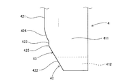
- FIG. 8 shows an enlarged view of the periphery of the insertion slit 42 in the counter plate portion 411.
- the insertion slit 42 of the present example includes a slit main body 421 formed by end surfaces 43 parallel to each other in a pair of opposing plate portions 411 and a distal end plate portion 412 continuous from the slit main body portion 421. And a slit guide portion 422 that is tapered toward the opening side.
- a wide portion 423 that is parallel to the slit main body portion 421 and wider than the slit main body portion 421 is formed on the back side opposite to the opening side of the slit guide portion 422.
- a tapered portion 424 connected to the slit main body portion 421 is formed on the back side of the wide portion 423.
- the tapered portion 424 is formed in a round shape that swells toward the insertion slit 42 side. Further, an edge-shaped corner portion 425 is formed between the slit guide portion 422 and the wide portion 423.
- the slit guide portion 422 is a portion that stably guides the winding end portion 213 to the slit body portion 421 when the winding end portion 213 of the primary coil 21 is inserted into the insertion slit 42.
- the edge-shaped corner portion 425 functions as a portion for scraping (peeling) the insulating coating 212B at the winding end 213 when the winding end 213 of the primary coil 21 is inserted into the insertion slit 42.
- the taper portion 424 functions as a portion for cutting the conductor portion 212A of the winding end portion 213 from which the insulating coating 212B has been cut when the winding end portion 213 of the primary coil 21 is inserted into the insertion slit 42.
- the winding end portion 213 of the primary coil 21 is pressed into contact with the slit main body portion 421 by removing a part of the insulating coating 212B and the conductor portion 212A.
- FIG. 7 shows the insertion part 41 of the terminal 4 as viewed from below.
- the insertion slit 42 is provided in the front end plate portion 412 and the pair of opposing plate portions 411 from below, and the front end plate portion 412 is divided to continue to the pair of opposing plate portions 411. Is formed.
- Each end face 43 of the slit guide part 422, the wide part 423, the taper part 424, and the slit main body part 421 in the insertion slit 42 can be formed perpendicular to the plate surface of the opposing plate part 411.
- each end face 43 of the insertion slit 42 can be formed in a cross-sectional shape with a sharp tip as shown in FIGS. 9 sharpens the outer ends of a pair of opposing plate portions 411 facing each other on each end surface 43, and FIG. 10 sharpens the inner ends of the pair of facing plate portions 411 facing each other on each end surface 43.
- FIG. 11 shows a case where the center portions of a pair of opposed plate portions 411 facing each other are sharpened at each end face 43.
- the structure of the winding end portion 213 of the primary coil 21 and the terminal 4 that conducts this is devised.
- a pair of terminals 4 are provided in the connector case portion 3, and the insertion portions 41 of the pair of terminals 4 are inserted toward the fitting direction A between the coil portion 2 and the connector case portion 3.
- a slit 42 is formed.
- the winding end portions 213 at both ends of the primary coil 21 are drawn substantially along the winding direction B of the primary electric wire 212.
- the winding end portion 213 of the primary coil 21 is inserted into the fitting hole 31 when the coil portion 2 is fitted to the connector case portion 3. It is inserted into the insertion slit 42 of the part 41.
- each winding end portion 213 is guided to the center side of the opposing plate portion 411 by the slit guide portion 422, and an edge-shaped corner portion is obtained.
- the insulating coating 212B is shaved.
- Each winding end 213 passes through the pair of wide portions 423, and then a part of the conductor portion 212 ⁇ / b> A is scraped by the taper portion 424, and the remaining portion of the conductor portion 212 ⁇ / b> A is pressed against the terminal 4.
- the winding end 213 and the terminal 4 are joined by pressure contact between the winding end 213 and the terminal 4.
- the coil part 2 and the connector case part 3 can be fitted, and at the same time, the pair of winding end parts 213 and the pair of terminals 4 can be pressed. Therefore, the pair of winding end portions 213 and the pair of terminals 4 can be joined (pressure contact) very easily, and the number of assembling steps of the ignition coil 1 can be reduced.
- the epoxy resin 6 is filled around the terminal 4, and stress is generated when the epoxy resin 6 is cured.
- the stress acting on the epoxy resin 6 is generated on the contraction side and acts in the direction of narrowing the width of the insertion slit 42 of the terminal 4.
- the front end plate portion 412 connected to the front end portions of the pair of opposing plate portions 411 is arranged in parallel with the winding end portion 213, it becomes easier to receive the curing shrinkage force of the epoxy resin 6, and more reliably.
- the conductor portion 212A of the winding end 213 can be brought into pressure contact with the terminal 4.
- the pair of terminals 4 are provided in the connector case portion 3 and the structure in which the pair of winding end portions 213 and the pair of terminals 4 are press-contacted is adopted, the joining of the terminals 4 can be eliminated. Thereby, the assembly man-hour and the number of parts of the ignition coil 1 can be reduced.
- the winding end portions 213 at both ends of the primary coil 21 are drawn substantially along the winding direction B of the primary electric wire 212. Thereby, it can prevent that the primary coil 21 becomes large in the axial direction (same as the fitting direction A) of the primary spool 211. Therefore, the ignition coil 1 can be reduced in size in the axial direction. Moreover, the ignition coil 1 can also be reduced in size by eliminating the joining of the terminals 4.
- the number of assembling steps and the number of parts can be reduced, and the size can be reduced.
- this invention is not necessarily limited to the Example mentioned above, Unless it deviates from the summary of this invention as described in a claim, it can expand
Landscapes
- Engineering & Computer Science (AREA)
- Power Engineering (AREA)
- Chemical & Material Sciences (AREA)
- Combustion & Propulsion (AREA)
- Mechanical Engineering (AREA)
- General Engineering & Computer Science (AREA)
- Ignition Installations For Internal Combustion Engines (AREA)
Abstract
Description
いる。
2 コイル部
21 一次コイル
211 一次スプール
212 一次電線
213 巻線端部
22 二次コイル
23 コイルケース
3 コネクタケース部
31 嵌合穴
32 コネクタ部
4 ターミナル
41 差込部
411 対向板部
412 先端板部
42 差込スリット
421 スリット本体部
422 スリットガイド部
423 幅広部
424 テーパ部
425 角部
Claims (12)
- 内外周に同心状に配置された一次コイル(21)及び二次コイル(22)がコイルケース(23)内に配置されて形成されたコイル部(2)と、
該コイル部(2)の端部を嵌合する嵌合穴(31)が形成され、上記一次コイル(21)の通電及びその遮断を行うためのコネクタ部(32)を有するコネクタケース部(3)とを備えており、
上記一次コイル(21)は、樹脂製の一次スプール(211)の外周に一次電線(212)を巻回して形成されており、
上記コネクタケース部(3)には、上記嵌合穴(31)内から上記コネクタ部(32)まで配置された導体からなるターミナル(4)が設けられており、
該ターミナル(4)において、上記嵌合穴(31)内に配置された差込部(41)には、上記コイル部(2)と上記コネクタケース部(3)との嵌合方向(A)に向けて、差込スリット(42)が形成されており、
上記一次コイル(21)の巻線端部(213)は、上記一次電線(212)の巻回方向(B)にほぼ沿って引き出されており、かつ、上記嵌合方向(A)において、上記差込スリット(42)に差し込まれていることを特徴とする内燃機関用点火コイル(1)。 - 請求項1に記載の内燃機関用点火コイル(1)において、上記差込部(41)は、帯板形状の板面が互いに向き合う一対の対向板部(411)と、該一対の対向板部(411)の先端部同士に繋がる先端板部(412)とを有しており、
上記差込スリット(42)は、上記先端板部(412)を分断して上記一対の対向板部(411)まで連続して形成されていることを特徴とする内燃機関用点火コイル(1)。 - 請求項1又は2に記載の内燃機関用点火コイル(1)において、上記一次スプール(211)の端部には、上記差込スリット(42)に上記一次コイル(21)の巻線端部(213)を差し込む際に、該巻線端部(213)をバックアップするバックアップ部(215)が形成されていることを特徴とする内燃機関用点火コイル(1)。
- 請求項1又は2に記載の内燃機関用点火コイル(1)において、上記一次コイル(21)の巻線端部(213)は、上記一次スプール(211)の周方向における互いに対向する位置に一対に引き出されており、
上記ターミナル(4)は、上記コネクタケース部(3)内に一対に配設されており、
該一対のターミナル(4)に設けられた上記差込部(41)は、上記コネクタケース部(3)における上記嵌合穴(31)の周方向における互いに対向する位置に一対に配置されており、
上記コイル部(2)と上記コネクタケース部(3)とを嵌合することにより、上記一対の巻線端部(213)を上記一対の差込部(41)における上記差込スリット(42)に差し込むよう構成されていることを特徴とする内燃機関用点火コイル(1)。 - 請求項1又は2に記載の内燃機関用点火コイル(1)において、
上記差込スリット(42)は、上記一対の対向板部(411)において、互いに平行な端面によって形成されたスリット本体部(421)と、該スリット本体部(421)から連続して上記先端板部(412)が位置する開口側に形成され、該開口側に向けてテーパ状に広がるスリットガイド部(422)とを有していることを特徴とする内燃機関用点火コイル(1)。 - 請求項1又は2に記載の内燃機関用点火コイル(1)において、
上記スリットガイド部(422)における上記開口側とは反対側の奥側には、上記スリット本体部(421)に対して平行で該スリット本体部(421)よりも幅が広い幅広部(423)が形成されており、
該幅広部(423)における上記奥側には、上記スリット本体部(421)に繋がるテーパ部(424)が形成されており、
上記スリットガイド部(422)と上記幅広部(423)との間には、エッジ形状の角部(425)が形成されていることを特徴とする内燃機関用点火コイル(1)。 - 請求項1又は2のいずれか一項に記載の内燃機関用点火コイル(1)において、上記一次コイル(21)の巻線端部(213)は、上記一次スプール(211)の周方向における互いに対向する位置に一対に引き出されており、
上記ターミナル(4)は、上記コネクタケース部(3)内に一対に配設されており、
該一対のターミナル(4)に設けられた上記差込部(41)は、上記コネクタケース部(3)における上記嵌合穴(31)の周方向における互いに対向する位置に一対に配置されており、
上記コイル部(2)と上記コネクタケース部(3)とを嵌合することにより、上記一対の巻線端部(213)を上記一対の差込部(41)における上記差込スリット(42)に差し込むよう構成されていることを特徴とする内燃機関用点火コイル(1)。 - 請求項7に記載の内燃機関用点火コイル(1)において、
上記差込スリット(42)は、上記一対の対向板部(411)において、互いに平行な端面によって形成されたスリット本体部(421)と、該スリット本体部(421)から連続して上記先端板部(412)が位置する開口側に形成され、該開口側に向けてテーパ状に広がるスリットガイド部(422)とを有していることを特徴とする内燃機関用点火コイル(1)。 - 請求項8に記載の内燃機関用点火コイル(1)において、
上記スリットガイド部(422)における上記開口側とは反対側の奥側には、上記スリット本体部(421)に対して平行で該スリット本体部(421)よりも幅が広い幅広部(423)が形成されており、
該幅広部(423)における上記奥側には、上記スリット本体部(421)に繋がるテーパ部(424)が形成されており、
上記スリットガイド部(422)と上記幅広部(423)との間には、エッジ形状の角部(425)が形成されていることを特徴とする内燃機関用点火コイル(1)。 - 請求項4に記載の内燃機関用点火コイル(1)において、
上記差込スリット(42)は、上記一対の対向板部(411)において、互いに平行な端面によって形成されたスリット本体部(421)と、該スリット本体部(421)から連続して上記先端板部(412)が位置する開口側に形成され、該開口側に向けてテーパ状に広がるスリットガイド部(422)とを有していることを特徴とする内燃機関用点火コイル(1)。 - 請求項10に記載の内燃機関用点火コイル(1)において、
上記スリットガイド部(422)における上記開口側とは反対側の奥側には、上記スリット本体部(421)に対して平行で該スリット本体部(421)よりも幅が広い幅広部(423)が形成されており、
該幅広部(423)における上記奥側には、上記スリット本体部(421)に繋がるテーパ部(424)が形成されており、
上記スリットガイド部(422)と上記幅広部(423)との間には、エッジ形状の角部(425)が形成されていることを特徴とする内燃機関用点火コイル(1)。 - 請求項5に記載の内燃機関用点火コイル(1)において、
上記スリットガイド部(422)における上記開口側とは反対側の奥側には、上記スリット本体部(421)に対して平行で該スリット本体部(421)よりも幅が広い幅広部(423)が形成されており、
該幅広部(423)における上記奥側には、上記スリット本体部(421)に繋がるテーパ部(424)が形成されており、
上記スリットガイド部(422)と上記幅広部(423)との間には、エッジ形状の角部(425)が形成されていることを特徴とする内燃機関用点火コイル(1)。
Priority Applications (3)
| Application Number | Priority Date | Filing Date | Title |
|---|---|---|---|
| CN201280049117.8A CN103858188B (zh) | 2011-10-06 | 2012-10-04 | 内燃机用点火线圈 |
| DE112012004182.8T DE112012004182T5 (de) | 2011-10-06 | 2012-10-04 | Zündspule für eine Brennkraftmaschine |
| US14/349,482 US9343211B2 (en) | 2011-10-06 | 2012-10-04 | Ignition coil for internal combustion engine |
Applications Claiming Priority (4)
| Application Number | Priority Date | Filing Date | Title |
|---|---|---|---|
| JP2011221678 | 2011-10-06 | ||
| JP2011-221678 | 2011-10-06 | ||
| JP2012-159184 | 2012-07-18 | ||
| JP2012159184A JP5532083B2 (ja) | 2011-10-06 | 2012-07-18 | 内燃機関用点火コイル |
Publications (1)
| Publication Number | Publication Date |
|---|---|
| WO2013051654A1 true WO2013051654A1 (ja) | 2013-04-11 |
Family
ID=48043807
Family Applications (1)
| Application Number | Title | Priority Date | Filing Date |
|---|---|---|---|
| PCT/JP2012/075819 Ceased WO2013051654A1 (ja) | 2011-10-06 | 2012-10-04 | 内燃機関用点火コイル |
Country Status (5)
| Country | Link |
|---|---|
| US (1) | US9343211B2 (ja) |
| JP (1) | JP5532083B2 (ja) |
| CN (1) | CN103858188B (ja) |
| DE (1) | DE112012004182T5 (ja) |
| WO (1) | WO2013051654A1 (ja) |
Cited By (1)
| Publication number | Priority date | Publication date | Assignee | Title |
|---|---|---|---|---|
| JP2018133546A (ja) * | 2017-02-17 | 2018-08-23 | ヴィオニア日信ブレーキシステムジャパン株式会社 | コイル組立体およびブレーキ制御装置 |
Families Citing this family (8)
| Publication number | Priority date | Publication date | Assignee | Title |
|---|---|---|---|---|
| JP5720652B2 (ja) | 2012-10-17 | 2015-05-20 | 株式会社デンソー | 内燃機関用点火コイル |
| DE102014209185A1 (de) * | 2013-11-14 | 2015-05-21 | Robert Bosch Gmbh | Elektronikmodul für eine Zündeinheit |
| JP6350143B2 (ja) | 2014-09-08 | 2018-07-04 | 株式会社デンソー | 内燃機関用の点火コイル |
| CN204424070U (zh) * | 2014-09-29 | 2015-06-24 | 浙江沃得尔科技有限公司 | 点火线圈内的初级线圈结构 |
| CN109637775B (zh) * | 2017-10-06 | 2023-11-07 | 株式会社电装 | 内燃机用的点火线圈 |
| JP7225728B2 (ja) * | 2018-11-21 | 2023-02-21 | 株式会社デンソー | 点火コイル |
| KR102652969B1 (ko) * | 2021-10-21 | 2024-03-29 | 주식회사 유라테크 | 점화코일 |
| JP2023169680A (ja) * | 2022-05-17 | 2023-11-30 | ダイヤゼブラ電機株式会社 | 点火コイル |
Citations (6)
| Publication number | Priority date | Publication date | Assignee | Title |
|---|---|---|---|---|
| JPS62500621A (ja) * | 1984-10-17 | 1987-03-12 | アンプ・インコ−ポレ−テッド | 選択ハンダ・スロット型成端方法および製品 |
| JPH0224525U (ja) * | 1988-08-01 | 1990-02-19 | ||
| JPH045622U (ja) * | 1990-04-28 | 1992-01-20 | ||
| US5295861A (en) * | 1991-12-23 | 1994-03-22 | Ford Motor Company | Connector for ignition coil assembly |
| JPH0963870A (ja) * | 1995-08-21 | 1997-03-07 | Hanshin Electric Co Ltd | 内燃機関用モールド型点火コイル |
| JP2003124043A (ja) * | 2001-10-18 | 2003-04-25 | Denso Corp | 点火コイル |
Family Cites Families (6)
| Publication number | Priority date | Publication date | Assignee | Title |
|---|---|---|---|---|
| US4926548A (en) * | 1984-10-17 | 1990-05-22 | Amp Incorporated | Select solder slot termination method |
| US5225801A (en) * | 1990-04-28 | 1993-07-06 | Toyo Denso Kabushiki Kaisha | Ignition coil device for engine |
| EP0827164A3 (en) * | 1996-08-31 | 1998-11-18 | Toyo Denso Kabushiki Kaisha | Engine igniting coil device and method of winding an ignition coil |
| CN2365786Y (zh) * | 1998-10-09 | 2000-02-23 | 杨建军 | 电气活动连接插座 |
| CN2356426Y (zh) * | 1998-11-23 | 1999-12-29 | 美安五金电子(深圳)有限公司 | 推压式同轴电缆连接插座 |
| JP4342471B2 (ja) * | 2005-05-12 | 2009-10-14 | 三菱電機株式会社 | 内燃機関用点火コイル装置 |
-
2012
- 2012-07-18 JP JP2012159184A patent/JP5532083B2/ja active Active
- 2012-10-04 CN CN201280049117.8A patent/CN103858188B/zh not_active Expired - Fee Related
- 2012-10-04 US US14/349,482 patent/US9343211B2/en not_active Expired - Fee Related
- 2012-10-04 WO PCT/JP2012/075819 patent/WO2013051654A1/ja not_active Ceased
- 2012-10-04 DE DE112012004182.8T patent/DE112012004182T5/de not_active Withdrawn
Patent Citations (6)
| Publication number | Priority date | Publication date | Assignee | Title |
|---|---|---|---|---|
| JPS62500621A (ja) * | 1984-10-17 | 1987-03-12 | アンプ・インコ−ポレ−テッド | 選択ハンダ・スロット型成端方法および製品 |
| JPH0224525U (ja) * | 1988-08-01 | 1990-02-19 | ||
| JPH045622U (ja) * | 1990-04-28 | 1992-01-20 | ||
| US5295861A (en) * | 1991-12-23 | 1994-03-22 | Ford Motor Company | Connector for ignition coil assembly |
| JPH0963870A (ja) * | 1995-08-21 | 1997-03-07 | Hanshin Electric Co Ltd | 内燃機関用モールド型点火コイル |
| JP2003124043A (ja) * | 2001-10-18 | 2003-04-25 | Denso Corp | 点火コイル |
Cited By (1)
| Publication number | Priority date | Publication date | Assignee | Title |
|---|---|---|---|---|
| JP2018133546A (ja) * | 2017-02-17 | 2018-08-23 | ヴィオニア日信ブレーキシステムジャパン株式会社 | コイル組立体およびブレーキ制御装置 |
Also Published As
| Publication number | Publication date |
|---|---|
| CN103858188B (zh) | 2017-02-15 |
| JP2013093545A (ja) | 2013-05-16 |
| JP5532083B2 (ja) | 2014-06-25 |
| CN103858188A (zh) | 2014-06-11 |
| US9343211B2 (en) | 2016-05-17 |
| US20140345582A1 (en) | 2014-11-27 |
| DE112012004182T5 (de) | 2014-06-26 |
Similar Documents
| Publication | Publication Date | Title |
|---|---|---|
| JP5532083B2 (ja) | 内燃機関用点火コイル | |
| JP4975173B1 (ja) | 内燃機関の点火コイル装置 | |
| JP5018319B2 (ja) | 点火コイル | |
| CN107004498B (zh) | 内燃机用点火线圈 | |
| JP5720652B2 (ja) | 内燃機関用点火コイル | |
| JP4342471B2 (ja) | 内燃機関用点火コイル装置 | |
| JP4969770B2 (ja) | スティック型点火コイル及びその1次コイルアセンブリの組付け方法 | |
| JP2008053677A (ja) | 点火コイル | |
| JP2011077485A (ja) | 内燃機関用点火コイル | |
| US7392799B2 (en) | Ignition coil and method for manufacturing the same | |
| JP4158180B2 (ja) | 内燃機関用点火装置 | |
| JP6028823B2 (ja) | 内燃機関用点火コイル | |
| JP6500519B2 (ja) | 内燃機関用の点火コイル | |
| JP2008270392A (ja) | 内燃機関用点火コイル | |
| CN203260461U (zh) | 内燃机用点火线圈 | |
| JP2009158560A (ja) | 内燃機関用点火コイル | |
| JP2009167978A (ja) | 点火コイル | |
| JP2008277461A (ja) | 点火コイル | |
| JP2008004732A (ja) | 内燃機関用点火コイル及びその組立方法 | |
| JP2011023578A (ja) | 内燃機関用点火コイル | |
| JP2008135494A (ja) | 内燃機関用点火コイル | |
| JP2008243930A (ja) | 内燃機関用点火コイルおよびコイルにおけるコイル電線の端末処理方法 | |
| JP2009140989A (ja) | 点火コイル及びその組付方法 | |
| JP2010116897A (ja) | 内燃機関用点火コイル | |
| JP2007329332A (ja) | 点火コイル |
Legal Events
| Date | Code | Title | Description |
|---|---|---|---|
| 121 | Ep: the epo has been informed by wipo that ep was designated in this application |
Ref document number: 12838267 Country of ref document: EP Kind code of ref document: A1 |
|
| WWE | Wipo information: entry into national phase |
Ref document number: 14349482 Country of ref document: US |
|
| WWE | Wipo information: entry into national phase |
Ref document number: 1120120041828 Country of ref document: DE Ref document number: 112012004182 Country of ref document: DE |
|
| 122 | Ep: pct application non-entry in european phase |
Ref document number: 12838267 Country of ref document: EP Kind code of ref document: A1 |