WO2013035859A1 - リチウムイオン二次電池用炭素材、リチウムイオン二次電池用負極材およびリチウムイオン二次電池 - Google Patents
リチウムイオン二次電池用炭素材、リチウムイオン二次電池用負極材およびリチウムイオン二次電池 Download PDFInfo
- Publication number
- WO2013035859A1 WO2013035859A1 PCT/JP2012/072966 JP2012072966W WO2013035859A1 WO 2013035859 A1 WO2013035859 A1 WO 2013035859A1 JP 2012072966 W JP2012072966 W JP 2012072966W WO 2013035859 A1 WO2013035859 A1 WO 2013035859A1
- Authority
- WO
- WIPO (PCT)
- Prior art keywords
- lithium ion
- ion secondary
- secondary battery
- carbon material
- carbon
- Prior art date
Links
Images
Classifications
-
- C—CHEMISTRY; METALLURGY
- C01—INORGANIC CHEMISTRY
- C01B—NON-METALLIC ELEMENTS; COMPOUNDS THEREOF; METALLOIDS OR COMPOUNDS THEREOF NOT COVERED BY SUBCLASS C01C
- C01B32/00—Carbon; Compounds thereof
- C01B32/20—Graphite
-
- C—CHEMISTRY; METALLURGY
- C01—INORGANIC CHEMISTRY
- C01B—NON-METALLIC ELEMENTS; COMPOUNDS THEREOF; METALLOIDS OR COMPOUNDS THEREOF NOT COVERED BY SUBCLASS C01C
- C01B32/00—Carbon; Compounds thereof
-
- C—CHEMISTRY; METALLURGY
- C01—INORGANIC CHEMISTRY
- C01B—NON-METALLIC ELEMENTS; COMPOUNDS THEREOF; METALLOIDS OR COMPOUNDS THEREOF NOT COVERED BY SUBCLASS C01C
- C01B32/00—Carbon; Compounds thereof
- C01B32/05—Preparation or purification of carbon not covered by groups C01B32/15, C01B32/20, C01B32/25, C01B32/30
-
- H—ELECTRICITY
- H01—ELECTRIC ELEMENTS
- H01M—PROCESSES OR MEANS, e.g. BATTERIES, FOR THE DIRECT CONVERSION OF CHEMICAL ENERGY INTO ELECTRICAL ENERGY
- H01M10/00—Secondary cells; Manufacture thereof
- H01M10/05—Accumulators with non-aqueous electrolyte
- H01M10/052—Li-accumulators
-
- H—ELECTRICITY
- H01—ELECTRIC ELEMENTS
- H01M—PROCESSES OR MEANS, e.g. BATTERIES, FOR THE DIRECT CONVERSION OF CHEMICAL ENERGY INTO ELECTRICAL ENERGY
- H01M10/00—Secondary cells; Manufacture thereof
- H01M10/05—Accumulators with non-aqueous electrolyte
- H01M10/052—Li-accumulators
- H01M10/0525—Rocking-chair batteries, i.e. batteries with lithium insertion or intercalation in both electrodes; Lithium-ion batteries
-
- H—ELECTRICITY
- H01—ELECTRIC ELEMENTS
- H01M—PROCESSES OR MEANS, e.g. BATTERIES, FOR THE DIRECT CONVERSION OF CHEMICAL ENERGY INTO ELECTRICAL ENERGY
- H01M4/00—Electrodes
- H01M4/02—Electrodes composed of, or comprising, active material
- H01M4/36—Selection of substances as active materials, active masses, active liquids
- H01M4/362—Composites
- H01M4/364—Composites as mixtures
-
- H—ELECTRICITY
- H01—ELECTRIC ELEMENTS
- H01M—PROCESSES OR MEANS, e.g. BATTERIES, FOR THE DIRECT CONVERSION OF CHEMICAL ENERGY INTO ELECTRICAL ENERGY
- H01M4/00—Electrodes
- H01M4/02—Electrodes composed of, or comprising, active material
- H01M4/36—Selection of substances as active materials, active masses, active liquids
- H01M4/58—Selection of substances as active materials, active masses, active liquids of inorganic compounds other than oxides or hydroxides, e.g. sulfides, selenides, tellurides, halogenides or LiCoFy; of polyanionic structures, e.g. phosphates, silicates or borates
- H01M4/583—Carbonaceous material, e.g. graphite-intercalation compounds or CFx
- H01M4/587—Carbonaceous material, e.g. graphite-intercalation compounds or CFx for inserting or intercalating light metals
-
- H—ELECTRICITY
- H01—ELECTRIC ELEMENTS
- H01M—PROCESSES OR MEANS, e.g. BATTERIES, FOR THE DIRECT CONVERSION OF CHEMICAL ENERGY INTO ELECTRICAL ENERGY
- H01M4/00—Electrodes
- H01M4/02—Electrodes composed of, or comprising, active material
- H01M4/62—Selection of inactive substances as ingredients for active masses, e.g. binders, fillers
-
- Y—GENERAL TAGGING OF NEW TECHNOLOGICAL DEVELOPMENTS; GENERAL TAGGING OF CROSS-SECTIONAL TECHNOLOGIES SPANNING OVER SEVERAL SECTIONS OF THE IPC; TECHNICAL SUBJECTS COVERED BY FORMER USPC CROSS-REFERENCE ART COLLECTIONS [XRACs] AND DIGESTS
- Y02—TECHNOLOGIES OR APPLICATIONS FOR MITIGATION OR ADAPTATION AGAINST CLIMATE CHANGE
- Y02E—REDUCTION OF GREENHOUSE GAS [GHG] EMISSIONS, RELATED TO ENERGY GENERATION, TRANSMISSION OR DISTRIBUTION
- Y02E60/00—Enabling technologies; Technologies with a potential or indirect contribution to GHG emissions mitigation
- Y02E60/10—Energy storage using batteries
-
- Y—GENERAL TAGGING OF NEW TECHNOLOGICAL DEVELOPMENTS; GENERAL TAGGING OF CROSS-SECTIONAL TECHNOLOGIES SPANNING OVER SEVERAL SECTIONS OF THE IPC; TECHNICAL SUBJECTS COVERED BY FORMER USPC CROSS-REFERENCE ART COLLECTIONS [XRACs] AND DIGESTS
- Y10—TECHNICAL SUBJECTS COVERED BY FORMER USPC
- Y10T—TECHNICAL SUBJECTS COVERED BY FORMER US CLASSIFICATION
- Y10T428/00—Stock material or miscellaneous articles
- Y10T428/29—Coated or structually defined flake, particle, cell, strand, strand portion, rod, filament, macroscopic fiber or mass thereof
- Y10T428/2982—Particulate matter [e.g., sphere, flake, etc.]
Definitions
- the present invention relates to a carbon material for a lithium ion secondary battery, a negative electrode material for a lithium ion secondary battery, and a lithium ion secondary battery.
- a carbon material is used as a constituent material (negative electrode material) of a negative electrode of a lithium ion secondary battery. This is because even when the charge / discharge cycle of the lithium ion secondary battery is repeated, dendritic lithium is not easily deposited on the negative electrode using the carbon material, and safety is guaranteed.
- An object of the present invention is to provide a carbon material for a lithium ion secondary battery, a negative electrode material for a lithium ion secondary battery, and a lithium ion secondary battery that can provide a well-balanced balance between high charge / discharge capacity and excellent charge / discharge efficiency. It is providing the lithium ion secondary battery provided with a characteristic.
- a carbon material used in a lithium ion secondary battery Including graphite as a main material of the carbon material, and hard carbon,
- the graphite content is A [wt%] and the hard carbon content is B [wt%]
- the relationship 1.2 ⁇ A / B ⁇ 19 is satisfied
- the graphite content Is a carbon material for a lithium ion secondary battery, characterized by being 55 wt% or more and 95 wt% or less.
- the carbon material is composed of a plurality of particles,
- D50 is 1.0 ⁇ m or more and 50 ⁇ m or less
- D95 / D5 is 2.0 or more and 30 or less.
- the graphite and the hard carbon are each composed of a plurality of particles, In the cumulative distribution on a volume basis, the 50% cumulative particle size of the graphite particles is 5 ⁇ m or more and 50 ⁇ m or less, and the 50% cumulative particle size of the hard carbon particles is 1 ⁇ m or more and 50 ⁇ m or less.
- the carbon material for a lithium ion secondary battery according to (3) is 5 ⁇ m or more and 50 ⁇ m or less.
- the carbon material is composed of a porous body having pores including mesopores and macropores, The ratio of the sum of the total volume of the mesopores and the total volume of the macropores to the total volume of the pores of the porous body is 80% or more and 98% or less,
- the positron lifetime of the hard carbon measured by the positron annihilation method is 370 picoseconds or more and 480 picoseconds or less
- C Measurement temperature and atmosphere: 25 ° C.
- a negative electrode material for a lithium ion secondary battery comprising the carbon material for a lithium ion secondary battery according to (1) above.
- a lithium ion secondary battery provided with can be provided.
- FIG. 1 is a diagram showing the relationship between the number of annihilation ⁇ rays and the positron annihilation time.
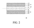
- FIG. 2 is a schematic diagram of a lithium ion secondary battery.
- the carbon material for a lithium ion secondary battery of the present invention includes graphite (graphite) as a main material and hard carbon.
- graphite has been used as the carbon material because it can increase the charge / discharge efficiency (discharge capacity / charge capacity) of the lithium ion secondary battery.
- charge / discharge efficiency discharge capacity / charge capacity
- graphite alone is used as a constituent material (negative electrode material) of a negative electrode of a lithium ion secondary battery
- the charge / discharge capacity is significantly reduced when the charge / discharge cycle of the lithium ion secondary battery is repeated.
- hard carbon non-graphitizable carbon obtained by firing a polymer whose graphite crystal structure is difficult to develop has been developed.
- hard carbon alone is used as the negative electrode material, the stability of the lithium ion secondary battery during the charge / discharge cycle can be improved and the input / output characteristics of the large current can be improved, but the charge / discharge efficiency (charge efficiency) And discharge efficiency) cannot be sufficiently obtained.
- a carbon material obtained by adding hard carbon to graphite as a main material is used as a negative electrode material of a lithium ion secondary battery.
- Graphite is one of allotropes of carbon, and is a hexagonal substance (hexagonal plate crystal) composed of a layered lattice in which six carbon rings are connected in layers.
- the charge / discharge cycle of the lithium ion secondary battery is made high, that is, the charge / discharge cycle is prevented while significantly reducing the charge / discharge efficiency.
- the stability at the time can be improved, and the input / output characteristics of a large current can be improved.
- the graphite content in the carbon material for a lithium ion secondary battery is preferably 55% by weight or more and 95% by weight or less, and more preferably 60% by weight or more and 85% by weight or less.
- the charge / discharge efficiency of the lithium ion secondary battery can be maintained high, the stability during the charge / discharge cycle can be increased, and the input / output characteristics of the large current can be improved.
- the graphite content is less than the lower limit, sufficient charge / discharge efficiency may not be obtained depending on the element structure of the lithium ion secondary battery, the composition of the electrolytic solution, and the like.
- even if the graphite content exceeds the upper limit further improvement in stability during charge / discharge cycle of the lithium ion secondary battery and improvement effect of input / output characteristics of large current cannot be expected.
- Hard carbon is a substance obtained by firing a polymer whose graphite crystal structure is difficult to develop.
- hard carbon is a substance obtained by carbonizing a resin or resin composition.
- Such hard carbon is amorphous (amorphous). Note that amorphous is a concept including an aggregate of fine crystals.
- Such hard carbon has high stability during the charge / discharge cycle of the lithium ion secondary battery, and can easily carry in and out a large current with respect to the lithium ion secondary battery.
- hard carbon alone is used as the negative electrode material, there is a problem that the charge / discharge efficiency of the lithium ion secondary battery cannot be obtained sufficiently.
- the carbon material for lithium ion secondary batteries of the present invention has excellent charge / discharge efficiency of lithium ion secondary batteries by adding hard carbon having the above characteristics to graphite as the main material.
- the stability during the charge / discharge cycle and the input / output characteristics of a large current can be improved.
- the content of such hard carbon in the carbon material for a lithium ion secondary battery is preferably 5% by weight or more and 45% by weight or less, and more preferably 15% by weight or more and 40% by weight or less.
- the lithium ion secondary battery is more effectively improved in stability during charge / discharge cycles and input / output characteristics of a large current without impairing excellent charge / discharge efficiency.
- the lithium ion secondary battery is more effective in terms of stability during charge / discharge cycles and high-current input / output characteristics without deteriorating the excellent charge / discharge efficiency. Become.
- the resin contained in the resin or resin composition, which is the raw material of the hard carbon is not particularly limited.
- crosslinked pitch etc. are mentioned, Among these, it can use combining 1 type (s) or 2 or more types.
- the resin composition contains the above resin as a main component and can contain a curing agent, an additive and the like. Further, the resin composition includes a crosslinking treatment by oxidation or the like. May be applied as appropriate.
- thermosetting resin is not particularly limited, and examples thereof include phenolic resins such as novolac type phenolic resin and resol type phenolic resin, epoxy resins such as bisphenol type epoxy resin and novolac type epoxy resin, melamine resin, urea resin, and aniline resin. , Cyanate resin, furan resin, ketone resin, unsaturated polyester resin, urethane resin and the like. Further, as the thermosetting resin, modified products obtained by modifying these resins with various components can also be used.
- thermoplastic resin is not particularly limited.
- polyethylene polystyrene, polyacrylonitrile, acrylonitrile-styrene (AS) resin, acrylonitrile-butadiene-styrene (ABS) resin, polypropylene, vinyl chloride, methacrylic resin, polyethylene terephthalate.
- Polyamide polycarbonate, polyacetal, polyphenylene ether, polybutylene terephthalate, polyphenylene sulfide, polysulfone, polyethersulfone, polyetheretherketone, polyetherimide, polyamideimide, polyimide, polyphthalamide and the like.
- thermosetting resin is preferable as the main resin used for hard carbon.
- the thermosetting resin is preferably selected from a novolak type phenol resin, a resol type phenol resin, a melamine resin, a furan resin, an aniline resin, and a modified product thereof.
- the freedom degree of design of a carbon material spreads, and a carbon material and a lithium ion secondary battery can be manufactured at low cost. Further, the stability during charge / discharge cycles of the lithium ion secondary battery and the input / output characteristics of a large current can be further improved.
- curing agent can be used together.
- the curing agent used is not particularly limited.
- the thermosetting resin is, for example, a novolac type phenol resin, hexamethylenetetramine, a resol type phenol resin, polyacetal, paraform or the like can be used as the curing agent.
- the thermosetting resin is, for example, an epoxy resin
- the curing agent includes polyamine compounds such as aliphatic polyamines and aromatic polyamines, acid anhydrides, imidazole compounds, dicyandiamide, novolac type phenol resins, and bisphenol type phenols.
- Known curing agents can be used for epoxy resins such as resins and resol type phenol resins.
- thermosetting resin that normally uses a predetermined amount of a curing agent
- an amount that is less than usual or that is used without a curing agent You can also.
- an additive in the resin composition as a raw material of hard carbon, an additive can be blended in addition to the above components.
- the additive used is not particularly limited, but for example, carbon material precursor carbonized at 200 to 800 ° C., organic acid, inorganic acid, nitrogen-containing compound, oxygen-containing compound, aromatic compound, non-ferrous A metal element etc. can be mentioned. These additives can be used alone or in combination of two or more depending on the type and properties of the resin used.
- a nitrogen-containing resin described later may be included as a main component resin.
- the main component resin may contain at least one nitrogen-containing compound as a component other than the main component resin, or a nitrogen-containing resin may be included as the main component resin.
- a nitrogen-containing compound may be included as a component other than the main component resin.
- examples of the nitrogen-containing resins include the following nitrogen-containing thermosetting resins and nitrogen-containing thermoplastic resins.
- the nitrogen-containing thermosetting resin include melamine resin, urea resin, aniline resin, cyanate resin, urethane resin, phenol resin modified with nitrogen-containing component such as amine, epoxy resin, and the like.
- nitrogen-containing thermoplastic resin examples include polyacrylonitrile, acrylonitrile-styrene (AS) resin, acrylonitrile-butadiene-styrene (ABS) resin, polyamide, polyetherimide, polyamideimide, polyimide, polyphthalamide and the like.
- the nitrogen-containing compound is not particularly limited.
- hexamethylenetetramine which is a curing agent for novolac type phenol resins, and a curing agent for epoxy resins.
- compounds containing nitrogen such as amine compounds, ammonium salts, nitrates, nitro compounds that do not function as curing agents can be used in addition to the curing agent component.
- the above-mentioned nitrogen-containing compounds can be used alone or in combination of two or more, regardless of whether the main component resin contains a nitrogen-containing resin or not. .
- the nitrogen content in the resin composition or resin used as the raw material for the hard carbon is not particularly limited, but is preferably 5% by weight to 65% by weight, and preferably 10% by weight to 20% by weight. More preferred.
- Hard carbon can be obtained by performing carbonization treatment of such a resin composition or resin, and the carbon content (carbon atom content) in the hard carbon is preferably 95% by weight or more, Further, the nitrogen content (the content of nitrogen atoms) is preferably 0.5% by weight or more and 5% by weight or less.
- the nitrogen content to 0.5% by weight or more, particularly 1.0% by weight or more, electrical characteristics suitable for hard carbon can be imparted by the electronegativity of nitrogen atoms.
- electrical characteristics suitable for hard carbon can be imparted by the electronegativity of nitrogen atoms.
- release of lithium ion by hard carbon can be accelerated
- the nitrogen content to 5% by weight or less, particularly 3% by weight or less, it is possible to prevent the electrical characteristics imparted to the hard carbon from becoming excessively strong, and lithium ions occluded in the hard carbon. Is prevented from causing more than necessary electric adsorption with nitrogen atoms. Thereby, it can suppress that an irreversible capacity
- the nitrogen content in the hard carbon is the above-mentioned resin composition or the nitrogen content in the resin, the conditions when carbonizing the resin composition or the resin, and the case where the curing treatment or the pre-carbonization treatment is performed before the carbonization treatment. In addition, these conditions can also be adjusted by appropriately setting.
- the nitrogen content in the resin composition or the resin is set as a predetermined value, and the conditions for carbonizing the resin, particularly the final temperature, are adjusted. A method is mentioned.
- a method for preparing a resin composition used as a raw material for hard carbon is not particularly limited. For example, a method in which the main component resin and other components are blended in a predetermined ratio, and these are melt mixed. Or a method in which these components are dissolved in a solvent and mixed, or a method in which these components are pulverized and mixed.
- the nitrogen content can be measured by, for example, a thermal conductivity method.
- This method is a method in which a measurement sample is converted into a simple gas (CO 2 , H 2 O, and N 2 ) using a combustion method, and then the gasified measurement sample is homogenized and then passed through a column. . Thereby, these gas is isolate
- Such a method can be carried out by using, for example, an elemental analysis measuring device “PE2400” manufactured by PerkinElmer.
- the hard carbon used in the present invention has a positron lifetime measured by a positron annihilation method of preferably 370 picoseconds or more and 480 picoseconds or less, and more preferably 380 picoseconds or more and 460 picoseconds or less.
- the positron lifetime measured by the positron annihilation method is not less than 370 picoseconds and not more than 480 picoseconds, it can be said that, as will be described later, voids having a size in which lithium ions easily enter and exit are formed in the hard carbon.
- the charge capacity and discharge capacity of the secondary battery can be further increased.
- the measurement of the positron lifetime by the positron annihilation method can be performed under the following conditions, for example.
- a Positron beam source A positron is generated from an electron / positron pair using an electron accelerator
- B Gamma ray detector: BaF 2 scintillator and photomultiplier tube
- C Measurement temperature and atmosphere: 25 ° C. in vacuum
- D Annihilation ⁇ -ray count: 3 ⁇ 10 6 or more
- E Positron beam energy: 10 keV
- the positron lifetime method is a method for measuring the size of the void by measuring the time from when the positron (e + ) enters the sample until it disappears.
- a positron is an antimatter of electrons and has the same static mass as an electron, but its charge is positive. It is known that when a positron is incident on a substance, it becomes a pair (positron-electron pair (positronium)) and then disappears.
- the positron When a positron is injected into the hard carbon, the positron (e + ) combines with one of the electrons struck out in the hard carbon to form positronium. Positronium is trapped in a portion of the hard carbon where the electron density is low, that is, a local void in the hard carbon, and overlaps with the electron cloud emitted from the void wall and disappears.
- the size of the voids and the annihilation lifetime of positronium are inversely related. That is, if the void is small, the overlap between positronium and surrounding electrons becomes large, and the positron annihilation lifetime is shortened. On the other hand, when the gap is large, the probability that the positronium overlaps with other electrons exuding from the gap wall and disappears becomes low, and the annihilation lifetime of the positronium becomes long. Therefore, the size of the voids in the hard carbon can be evaluated by measuring the annihilation lifetime of positronium.
- the positron incident on the hard carbon loses energy and then forms positronium and disappears together with the electron. At this time, ⁇ rays are emitted from the hard carbon. Therefore, the emitted ⁇ -ray becomes a measurement end signal.
- radioactive isotopes 22 Na is as a general-purpose. 22 Na emits positrons and 1.28 MeV gamma rays simultaneously when ⁇ + decays to 22 Ne. The positron incident on the hard carbon emits 511 keV gamma rays through an annihilation process.
- the annihilation lifetime of the positron can be obtained by measuring the time difference between the 1.28 MeV ⁇ ray and the 511 keV ⁇ ray as the end signal. Specifically, a positron lifetime spectrum as shown in FIG. 1 is obtained. The slope A of the positron lifetime spectrum indicates the positron lifetime, and the positron lifetime of the hard carbon can be grasped from the positron lifetime spectrum.
- an electron accelerator When an electron accelerator is used as the positron source, electron / positron pairs are generated by the braking X-rays generated by irradiating the target made of tantalum or tungsten with an electron beam, and positrons are generated.
- the time when the positron beam is incident on the hard carbon is taken as the measurement start point (corresponding to the start signal in 22 Na), and the end signal is measured as in the case of 22 Na. Can be implemented.
- the positron lifetime measured by the positron annihilation method is less than 370 picoseconds, the void size is too small, and the hard carbon may be difficult to occlude and release lithium ions.
- the positron lifetime measured by the positron annihilation method exceeds 480 picoseconds, the lithium ion occlusion amount of the hard carbon increases, but the capacitance increases due to the intrusion of other substances such as an electrolytic solution. Hard carbon may make it difficult to release lithium ions.
- the hard carbon preferably has a half width of a peak observed near 285 eV measured by X-ray photoelectron Spectroscopy (XPS method) of 0.8 eV or more and 1.8 eV or less, and 0.9 eV or more and 1.6 eV or less. It is more preferable that
- the half width of the peak observed near 285 eV measured by XPS method is 1.8 eV or less, most of the elements present on the surface of the hard carbon are due to inactive C—C bonds, etc.
- the carbon surface is substantially free of functional groups and impurities that react with active substances involved in ion conduction such as lithium ions.
- the full width at half maximum of the peak recognized in the vicinity of 285 eV is 0.8 eV or more, excessive crystallization does not occur in the hard carbon.
- the charge / discharge efficiency is reduced due to the irreversible capacity in the lithium ion secondary battery. Can be suppressed.
- the relationship between the XPS measurement and the surface state will be described.
- the surface of a solid sample is irradiated with X-rays, and the kinetic energy of photoelectrons emitted from the excited atoms is measured. This is a method for identifying constituent elements existing on the surface.
- the FT-IR method can also analyze the surface state of a solid sample, this FT-IR method identifies chemical bonds existing at a depth of about 1 ⁇ m from the surface of the solid sample, whereas XPS measurement In the method, an element existing at a depth of several millimeters from the surface of a solid sample can be identified. From this, it is preferable to use the XPS measurement method when identifying a functional group present in a region closer to the surface of the solid sample.
- the hard carbon preferably has an average interplanar spacing d 002 of (002) planes of 3.4 mm or more and 3.9 mm or less calculated from the wide angle X-ray diffraction method using the Bragg equation.
- the average interplanar distance d 002 is 3.4 mm or more, particularly 3.6 mm or more, the shrinkage / expansion between layers in the hard carbon laminated structure accompanying the occlusion of lithium ions is difficult to occur. Thereby, the fall of the charging / discharging cycling property of a lithium ion secondary battery can be suppressed.
- the average interplanar distance d 002 is 3.9 mm or less, particularly 3.8 mm or less, the lithium carbon is smoothly occluded and desorbed, and the charge / discharge efficiency of the lithium ion secondary battery is Can be suppressed.
- the hard carbon preferably has a crystallite size Lc in the c-axis direction (the (002) plane orthogonal direction) of 8 to 50 cm.
- Lc crystallite size in the c-axis direction (the (002) plane orthogonal direction) of 8 to 50 cm.
- Lc can be calculated as follows. Specifically, Lc can be determined using the following Scherrer equation from the half-value width and diffraction angle of the (002) plane peak in the spectrum obtained from the X-ray diffraction measurement.
- Lc 0.94 ⁇ / ( ⁇ cos ⁇ ) (Scherrer equation)
- Lc crystallite size
- ⁇ wavelength of characteristic X-ray K ⁇ 1 output from the cathode
- ⁇ half width of peak (radian)
- ⁇ Reflection angle of spectrum
- the X-ray diffraction spectrum of hard carbon can be measured, for example, with an X-ray diffractometer “XRD-7000” manufactured by Shimadzu Corporation.
- the method for measuring the average interplanar spacing of the hard carbon can be performed, for example, as follows. Specifically, the average interplanar spacing d can be calculated from the spectrum obtained from hard carbon X-ray diffraction measurement by the following Bragg equation.
- the hard carbon has a specific surface area of 15 m 2 / g or less and 1 m 2 / g or more according to the BET three-point method in nitrogen adsorption.
- the specific surface area by the BET three-point method in nitrogen adsorption is 15 m 2 / g or less, the reaction between the hard carbon (carbon material) and the electrolytic solution can be suppressed.
- appropriate permeability to the hard carbon of the electrolytic solution can be ensured by setting the specific surface area by the BET three-point method in nitrogen adsorption to 1 m 2 / g or more.
- the calculation method of the specific surface area can be performed as follows, for example. Specifically, the monomolecular adsorption amount Wm is calculated from the following formula (1), the total surface area Total is calculated from the following formula (2), and the specific surface area S can be obtained from the following formula (3).
- the hard carbon as described above can be manufactured, for example, as follows. First, a resin or resin composition to be carbonized is prepared.
- the apparatus for preparing the resin composition is not particularly limited.
- a kneading device such as a kneading roll, a single screw or a twin screw kneader can be used as the device.
- a mixing device such as a Henschel mixer or a disperser can be used as the device.
- a pulverizer such as a hammer mill or a jet mill can be used as the apparatus.
- the resin composition thus obtained may be one obtained by physically mixing a plurality of types of components contained therein, or mixed (stirring, kneading, etc.) during preparation of the resin composition. In this case, a part thereof may be chemically reacted with the mechanical energy applied and the thermal energy converted from the mechanical energy. Specifically, a plurality of types of components may be subjected to a mechanochemical reaction by mechanical energy or a chemical reaction by thermal energy.
- hard carbon is obtained by carbonizing such a resin composition or resin.
- the conditions for the carbonization treatment are not particularly limited.
- the temperature is raised from room temperature at 1 to 200 ° C./hour, and at 800 to 3000 ° C. for 0.1 to 50 hours, preferably 0.5 to 10 hours. It can be a condition for holding time.
- the carbonization treatment is preferably performed in an inert atmosphere such as nitrogen or helium gas, in a substantially inert atmosphere where a trace amount of oxygen is present in the inert gas, or in a reducing gas atmosphere.
- the conditions such as temperature and time during carbonization can be adjusted as appropriate in order to optimize the characteristics of the hard carbon.
- conditions for carbonization treatment are appropriately set according to the type of resin.
- the temperature during carbonization may be set to 1000 ° C. or higher, or the temperature increase rate may be set to less than 200 ° C./hour.
- the surface of hard carbon has an inactive functional group etc., and the half width of the peak recognized in the vicinity of 285 eV measured by XPS method is 0.8 eV or more and 1.8 eV or less. Carbon can be obtained more reliably.
- the pre-carbonization process can be performed to the said resin composition or resin.
- the conditions for the pre-carbonization treatment are not particularly limited, but may be, for example, 200 to 600 ° C. for 1 to 10 hours.
- a pre-carbonization treatment is performed in the absence of a reducing gas or an inert gas.
- the method of performing is mentioned.
- thermosetting resin or a polymerizable polymer compound when used as the resin for producing hard carbon, the resin composition or the resin can be cured before the pre-carbonization treatment.
- the curing treatment method is not particularly limited, and examples thereof include a method in which the resin composition is thermally cured by giving a heat amount capable of a curing reaction, or a method in which a resin and a curing agent are used in combination.
- the pre-carbonization treatment can be performed substantially in the solid phase.
- carbonization treatment or pre-carbonization treatment can be performed in a state in which the resin structure is maintained to some extent, and as a result, the structure and characteristics of the hard carbon can be controlled relatively easily.
- the processed product may be pulverized before the carbonization treatment.
- variation in the thermal history during carbonization treatment can be reduced, and the uniformity of the surface state of the hard carbon can be improved.
- the handleability of the processed product can be improved.
- the treated product is treated with the presence of a reducing gas or an inert gas. Then, it may be naturally cooled to 800 to 500 ° C. and then cooled at 100 ° C./hour until it becomes 100 ° C. or less.
- hard carbon having a positron lifetime measured by the positron annihilation method of 370 picoseconds or more and 480 picoseconds or less can be obtained.
- the carbon material as described above is preferably composed of a plurality of particles. Thereby, the surface area of the negative electrode of a lithium ion secondary battery can be increased, and the lithium ion occlusion amount in a negative electrode can be increased more reliably.
- the particle size at the time of 5% accumulation, the particle size at the time of 50% accumulation (average particle size), and the particle size at the time of 95% accumulation are respectively set to D5,
- D50 is preferably 1.0 ⁇ m or more and 50 ⁇ m or less
- D95 / D5 is preferably 2.0 or more and 30 or less.
- the charge / discharge capacity and charge / discharge efficiency of the lithium ion secondary battery can be further improved.
- the carbon material can be given good pressability, and the negative electrode material for the lithium ion secondary battery and the handling of the carbon material at the time of manufacturing the lithium ion secondary battery are facilitated.
- the lithium ion secondary battery Productivity of battery negative electrode materials and lithium ion secondary batteries is improved.
- the compression ratio of the carbon material at the time of manufacturing the lithium ion secondary battery is set to an optimum value, that is, A high-density negative electrode (electrode) can be produced, and an optimal conductive path for the negative electrode can be easily and reliably formed.
- the above excellent effects may not be obtained. That is, when D50 (average particle diameter) is less than the lower limit, the compression ratio when the carbon material is pressed cannot be reduced, and the compressed carbon material (carbon material layer) becomes bulky. There is a possibility that the handleability (ease of handling) may decrease. Moreover, since a specific surface area becomes large too much, there exists a possibility that the charging / discharging efficiency of the lithium ion secondary battery manufactured using a carbon material cannot fully be improved.
- D50 average particle size
- the smoothness of the coating film when the slurry is applied to the substrate is sufficiently high. It may be difficult to increase.
- the particles may crack, and the charge / discharge capacity of a lithium ion secondary battery produced using the carbon material is sufficiently improved. You may not be able to.
- the compression ratio when the carbon material is pressed is small and the movement of particles accompanying the compression is small, it may be difficult to obtain an optimal conductive path for the electrode.
- the compression ratio when the carbon material is pressed is also small, and the movement of particles accompanying the compression is small, so that it is difficult to obtain an optimal conductive path for the electrode. There is a fear.
- the electrode density cannot be sufficiently increased, and as a result, the charge / discharge capacity of the lithium ion secondary battery is sufficiently improved. You may not be able to. Further, the charge / discharge efficiency of the lithium ion secondary battery may not be sufficiently improved.
- the D50 (average particle diameter) of the particles is preferably 1.0 ⁇ m or more and 50 ⁇ m or less, more preferably 2.0 ⁇ m or more and 30 ⁇ m or less, and 2.0 ⁇ m or more and 15 ⁇ m or less. Is more preferable. Thereby, the effects as described above can be made more remarkable.
- the D95 / D5 of the particles is preferably 2.0 or more and 30 or less, more preferably 3.0 or more and 28 or less, and more preferably 4.0 or more and 20 or less. Further preferred. Thereby, the effects as described above can be made more remarkable.
- D5 of the particles is preferably from 0.1 ⁇ m to 10 ⁇ m, and more preferably from 0.5 ⁇ m to 5 ⁇ m.
- the D95 of the particles is preferably 1 ⁇ m or more and 100 ⁇ m or less, and more preferably 3 ⁇ m or more and 50 ⁇ m or less.
- the carbon material of the present invention has a density ratio (compression ratio) of the carbon material layer before and after pressing when the load per unit area is 2 t / cm 2 , that is, the carbon material before pressing.
- the value of d 1 / d 0 when the density of the layer is d 0 [g / cm 3 ] and the density of the carbon material layer after pressing is d 1 [g / cm 3 ] is 1.2 or more and 1.5 Or less, more preferably 1.3 or more and 1.4 or less.
- each of graphite and hard carbon may constitute separate particles, or a composite of graphite and hard carbon may constitute particles (composite particles). Good.
- the composite particles can be produced, for example, by mechanically colliding graphite particles and hard carbon particles.
- the particle size (average particle size) at the time of 50% accumulation of the graphite particles is 5 ⁇ m or more and 50 ⁇ m or less. It is preferable that the thickness is 5 ⁇ m or more and 30 ⁇ m or less. This makes it possible to produce a higher density negative electrode (electrode). Moreover, the lithium ion secondary battery manufactured using this negative electrode can maintain high charging / discharging efficiency.
- the content of graphite (graphite particles) is a value within the above range, the above-described conditions (D50 value and D95 / D5 value of the entire particle) should be satisfied easily and reliably.
- the charging / discharging efficiency of the lithium ion secondary battery can be increased, the stability during the charging / discharging cycle can be further improved, and the input / output characteristics of the large current can be further improved.
- the particle size (average particle size) at the time of 50% accumulation of the hard carbon particles in the volume-based cumulative distribution is 1 ⁇ m or more and 50 ⁇ m or less. It is preferable that it is 2 ⁇ m or more and 30 ⁇ m or less. Thereby, a higher density negative electrode can be produced.
- a resin contained in a resin or a resin composition which is a raw material of hard carbon (hard carbon particles) is obtained from novolac type phenol resin, resol type phenol resin, melamine resin, furan resin, aniline resin, and modified products thereof.
- the carbon material as described above is preferably composed of a porous body having pores including mesopores and macropores. Thereby, the surface area of the negative electrode of a lithium ion secondary battery can be increased, and the occlusion amount of lithium ions in the negative electrode can be increased more reliably.
- the ratio of the sum of the total volume of mesopores and the total volume of macropores to the total volume of pores of the porous body is 80% or more and 98% or less, and the macropores per unit weight of the porous body
- the volume is preferably 0.005 ml / g or more and 0.030 ml / g or less.
- the charge / discharge capacity of the lithium ion secondary battery and the current density at the time of charge / discharge can be increased, and fast charge and fast discharge can be realized.
- favorable press property can be provided to the carbon material for lithium ion secondary batteries
- productivity of the negative electrode can be improved.
- good pressability can be imparted to the carbon material, the negative electrode material for the lithium ion secondary battery, the compression ratio of the carbon material at the time of manufacturing the lithium ion secondary battery is set to an optimum value, that is, A high-density negative electrode (electrode) can be produced, and an optimal conductive path for the negative electrode can be easily and reliably formed.
- the ratio of the sum of the total volume of the mesopores and the total volume of the macropores to the total volume of the pores of the porous body is out of the above range, or the macropores per unit weight of the porous body When the volume is out of the above range, the above excellent effect may not be obtained. That is, when the ratio of the sum of the total volume of the mesopores and the total volume of the macropores to the total volume of the pores of the porous body is less than the lower limit, in the negative electrode manufactured using the carbon material, Therefore, the electrode density cannot be sufficiently increased, and as a result, the charge / discharge efficiency of the lithium ion secondary battery may not be sufficiently improved.
- the volume of the macropores per unit weight of the porous body is less than the lower limit, in the negative electrode manufactured using the carbon material, the number of paths through which the electrolyte solution permeates decreases, and the viscosity of the electrolyte solution Will slow down the diffusion of the electrolyte. For this reason, the current density at the time of charging / discharging of a lithium ion secondary battery may not be made high enough.
- the macropore volume per unit weight of the porous material exceeds the upper limit, the density of the carbon material (porous material) decreases, and the bulk of the carbon material may be large, making it difficult to handle.
- side reactions that are not related to charging / discharging between the carbon material (graphite and / or hard carbon) and the electrolytic solution increase, and the charge / discharge efficiency of the lithium ion secondary battery may not be sufficiently improved.
- a mesopore refers to a pore having a diameter of 2 nm or more and less than 50 nm
- a macropore refers to a pore having a diameter of 50 nm or more, and the diameter is less than 2 nm. These holes are called micropores.
- the ratio of the sum of the total volume of mesopores and the total volume of macropores to the total volume of pores of the porous body is preferably 80% or more and 98% or less, but 85% or more and 95%. % Or less is more preferable, and 85% or more and 92% or less is further preferable. Thereby, the effects as described above can be made more remarkable.
- the macropore volume per unit weight of the porous body is preferably 0.005 ml / g or more and 0.030 ml / g or less, but is 0.007 ml / g or more and 0.025 ml / g. More preferably, it is g or less. Thereby, the effects as described above can be made more remarkable.
- the volume of mesopores per unit weight of the porous body is preferably 0.001 ml / g or more and 0.025 ml / g or less, more preferably 0.003 ml / g or more and 0.020 ml / g or less.
- the ratio of the total volume of mesopores to the total volume of pores in the porous body is preferably 20% or more and 50% or less, and more preferably 30% or more and 45% or less.
- the ratio of the total volume of macropores to the total volume of pores in the porous body is preferably 30% or more and 70% or less, and more preferably 40% or more and 60% or less.
- the carbon material for a lithium ion secondary battery according to the present invention includes graphite as a main material and hard carbon, so the above-described conditions (total volume of mesopores relative to the total volume of pores of the porous body) And the total volume of macropores and the volume of macropores per unit weight of the porous body) can be satisfied easily and reliably. For this reason, the lithium ion secondary battery manufactured using the carbon material for lithium ion secondary batteries can be provided with a particularly good balance between high charge / discharge capacity and excellent charge / discharge efficiency.
- the graphite porous body When the carbon material is composed of a porous body, the graphite porous body has either one of mesopores or macropores, and the hard carbon porous body has the other pores.
- the porous body of graphite and hard carbon may have a structure having mesopores and macropores, respectively.
- the content of graphite is a value within the above-mentioned range (The ratio of the sum of the total volume of mesopores and the total volume of macropores to the total volume of pores in the entire porous body, and the volume of macropores per unit weight of the entire porous body) is easily and reliably satisfied.
- the charge / discharge efficiency of the lithium ion secondary battery can be increased, the stability during the charge / discharge cycle can be further improved, and the input / output characteristics of the large current can be further improved. .
- the content of hard carbon is a value within the above-described range.
- the ratio of the sum of the total volume of mesopores and the total volume of macropores to the total volume of pores of the entire porous body, and the volume of macropores per unit weight of the entire porous body easily and reliably The charge / discharge cycle stability and high-current input / output characteristics are more effectively enhanced without losing the excellent charge / discharge efficiency of the lithium ion secondary battery. be able to.
- the carbon material for a lithium ion secondary battery of the present invention is composed of a plurality of porous particles that satisfy the above-described conditions.
- the negative electrode material for a lithium ion secondary battery of the present invention includes the carbon material for a lithium ion secondary battery of the present invention as described above, and the lithium ion secondary battery of the present invention is for the lithium ion secondary battery of the present invention.
- a negative electrode material is provided.
- a lithium ion secondary battery having a high charge / discharge capacity and excellent charge / discharge efficiency in a well-balanced manner can be obtained.
- the large current characteristic of a lithium ion secondary battery can be improved by comprising a carbon material with a some particle
- the current density at the time of charging / discharging of a lithium ion secondary battery can be raised by comprising a carbon material with the porous body which has a mesopore and a macropore, and setting those ratios etc. suitably.
- FIG. 2 is a schematic diagram showing the configuration of the embodiment of the secondary battery.
- the secondary battery 10 includes a negative electrode 13, a positive electrode 21, an electrolytic solution 16, and a separator 18.
- the negative electrode 13 includes a negative electrode material 12 and a negative electrode current collector 14.
- the negative electrode current collector 14 is made of, for example, copper foil or nickel foil.
- the negative electrode material 12 is comprised by the carbon material for lithium ion secondary batteries of this invention as mentioned above.
- the negative electrode 13 can be manufactured as follows, for example. First, for 100 parts by weight of the carbon material for a lithium ion secondary battery, an organic polymer binder (fluorine polymer including polyethylene, polypropylene, etc., rubbery polymer such as butyl rubber, butadiene rubber, etc.) 1 to 30 parts by weight and an appropriate amount of a viscosity adjusting solvent (N-methyl-2-pyrrolidone, dimethylformamide, etc.) are added and kneaded to prepare a paste-like mixture. Next, the mixture is formed into a sheet shape, a pellet shape, or the like by compression molding, roll molding, or the like, and the negative electrode material 12 is obtained. And the negative electrode 13 can be obtained by laminating
- an organic polymer binder fluorine polymer including polyethylene, polypropylene, etc., rubbery polymer such as butyl rubber, butadiene rubber, etc.
- organic polymer binder fluorine polymer including polyethylene, polypropylene, etc., rubbery polymer such as butyl rubber, butadiene rubber, etc.
- a viscosity adjusting solvent N-methyl-2-pyrrolidone, dimethylformamide, etc.
- the electrolyte solution 16 fills the space between the positive electrode 21 and the negative electrode 13 and is a layer in which lithium ions move by charge / discharge.
- As the electrolytic solution 16 a solution obtained by dissolving a lithium salt serving as an electrolyte in a non-aqueous solvent is used.
- this non-aqueous solvent a mixture of cyclic esters such as propylene carbonate, ethylene carbonate and ⁇ -butyrolactone, chain esters such as dimethyl carbonate and diethyl carbonate, chain ethers such as dimethoxyethane, and the like can be used. it can.
- cyclic esters such as propylene carbonate, ethylene carbonate and ⁇ -butyrolactone
- chain esters such as dimethyl carbonate and diethyl carbonate
- chain ethers such as dimethoxyethane, and the like
- lithium metal salts such as LiClO 4 and LiPF 6 , tetraalkylammonium salts, and the like can be used. Further, the above salts can be mixed with polyethylene oxide, polyacrylonitrile, etc. and used as a solid electrolyte.
- the separator 18 is not particularly limited, and for example, a porous film such as polyethylene or polypropylene, a nonwoven fabric, or the like can be used.
- the positive electrode 21 includes a positive electrode material 20 and a positive electrode current collector 22.
- the positive electrode material 20 is not particularly limited, and for example, complex oxidation of lithium metal alone, lithium cobalt oxide (LiCoO 2 ), lithium nickel oxide (LiNiO 2 ), lithium manganese oxide (LiMn 2 O 4 ), or the like. Such as things. Further, the positive electrode material 20 can be used by adding a conductive polymer such as polyaniline or polypyrrole.
- the positive electrode current collector 22 for example, an aluminum foil can be used.
- the positive electrode 21 in this embodiment can be manufactured with the manufacturing method of the known positive electrode.
- Positron beam source An electron accelerator from the National Institute of Advanced Industrial Science and Technology (AIST) was used to generate electron / positron pairs and generate positrons (in the electron accelerator, an electron beam was applied to the target (tantalum)). Irradiation generated electron-positron pairs, generating positrons)
- B Gamma ray detector: BaF 2 scintillator and photomultiplier tube
- C Measurement temperature and atmosphere: 25 ° C.
- a baseline was drawn from both ends of the target peak, the distance from this baseline to the peak apex was measured, and this distance was taken as the peak intensity. This is because the base line of the spectrum that is usually obtained changes depending on the environment at the time of measurement and the difference in the sample.
- a baseline is drawn from both ends of the overlapping peak where they overlap.
- the peak half-value width was obtained by drawing a line parallel to the base line through a point having an intensity half of the peak intensity obtained above from the peak apex, and reading the energy at the intersection with both ends of the peak.
- Lc of hard carbon was measured as follows. Specifically, the Lc was determined from the half width of the (002) plane peak and the diffraction angle in the spectrum obtained by X-ray diffraction measurement of hard carbon using the following Scherrer equation.
- Lc 0.94 ⁇ / ( ⁇ cos ⁇ ) (Scherrer equation)
- Lc crystallite size
- ⁇ wavelength of characteristic X-ray K ⁇ 1 output from the cathode
- ⁇ half width of peak (radian)
- ⁇ Reflection angle of spectrum
- Carbon content and nitrogen content of hard carbon were measured using an elemental analysis measuring device “PE2400” manufactured by PerkinElmer. Specifically, the measurement sample was converted to CO 2 , H 2 O and N 2 using a combustion method, and then the gasified measurement sample was homogenized and then passed through a column. Thereby, these gases were separated stepwise, and the carbon, hydrogen and nitrogen contents in the hard carbon were measured from the respective thermal conductivities.
- the positive electrode was prepared using lithium metal, and the electrolyte was prepared by dissolving 1 mol / liter of lithium perchlorate in a mixed solution of ethylene carbonate and diethyl carbonate having a volume ratio of 1: 1. Using these, a bipolar coin cell for secondary battery evaluation was manufactured, and the following evaluation was performed on this bipolar coin cell.
- the charge capacity and discharge capacity for the second and subsequent times were determined as follows. After the bipolar coin cell is charged at a constant current density of 250 mA / g until the potential becomes 1 mV, it is charged while holding at a constant voltage of 1 mV until the current density is attenuated to 12.5 mA / g. The amount of electricity charged in the bipolar coin cell was defined as the charge capacity. On the other hand, the charged bipolar coin cell was discharged at a constant current of 250 mA / g current density, and the amount of electricity discharged until the potential (cut-off potential) became 1.5 V was defined as the discharge capacity.
- Particle size distribution Using a laser diffraction particle size distribution measuring apparatus LA-920 manufactured by Horiba, Ltd., the particle size distribution of the entire particles (graphite particles and hard carbon particles) constituting the carbon material by the laser diffraction method. The particle size distribution and particle size distribution of hard carbon particles were measured. From the measurement results, in the volume-based cumulative distribution, the particle size at the time of 5% accumulation (D5), the particle size at the time of 50% accumulation (D50, average particle size), and the particles at the time of 95% accumulation in the volume-based cumulative distribution The diameter (D95) was determined, and the particle diameter (D50, average particle diameter) at the time of 50% accumulation of the graphite particles and the hard carbon particles was determined.
- Example 2A to 5A A carbon material was obtained in the same manner as in Example 1A except that the contents of the graphite particles and the hard carbon particles were changed as shown in Table 1.
- Example 6A An aniline resin (synthesized by the following method) was used in place of the phenol resin in Example 1A.
- aniline resin 100 parts of aniline, 697 parts of a 37% formaldehyde aqueous solution, and 2 parts of oxalic acid are placed in a three-necked flask equipped with a stirrer and a condenser, reacted at 100 ° C. for 3 hours, and dehydrated to obtain 110 parts of aniline resin. It was.
- the obtained aniline resin had a weight average molecular weight of about 800.
- a resin composition obtained by pulverizing and mixing 100 parts of the aniline resin thus obtained and 10 parts of hexamethylenetetramine is treated in the same process as in Example 1A to obtain a carbon material. It was.
- Example 7A The same resin composition as in Example 6A was used. Further, in the treatment of the resin composition, a carbon material was obtained in the same manner as in Example 6A, except that the steps (d) and (e) of Example 1A were changed as follows.
- Example 2A A carbon material composed of the hard carbon particles of Example 1A was prepared.
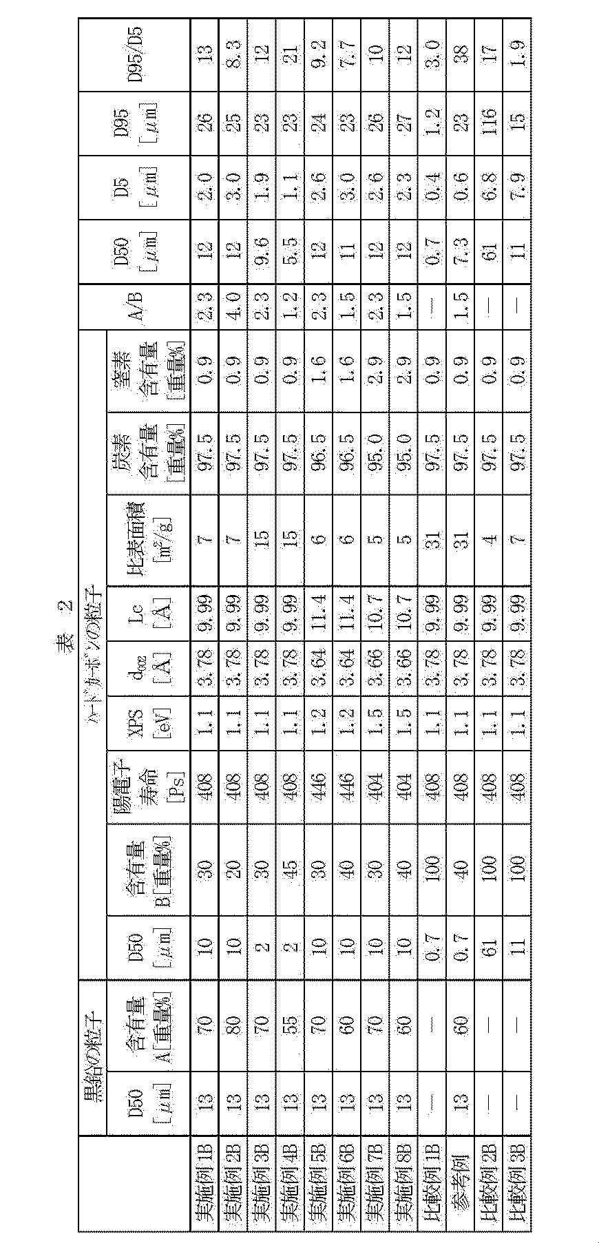
- the graphite particle content, the hard carbon particle content, the hard carbon positron lifetime, XPS, the average face spacing, the crystallite size, and the specific surface area are shown in Table 1.
- Table 1 also shows the charge capacity, discharge capacity, and charge / discharge efficiency of a bipolar coin cell (lithium ion secondary battery) including a negative electrode formed using the carbon material obtained in each example and comparative example. Indicated.
- a lithium ion secondary battery using a carbon material obtained by adding hard carbon particles to graphite particles has high charge / discharge efficiency, stability during charge / discharge cycles, and large The current input / output characteristics were also excellent. On the other hand, in the comparative example, sufficient results were not obtained.
- Example 1B As the resin composition, phenol resin PR-217 (manufactured by Sumitomo Bakelite Co., Ltd.) was processed in the order of the following steps (a) to (f) to obtain hard carbon particles.
- Example 2B A carbon material was obtained in the same manner as in Example 1B except that the contents of the graphite particles and the hard carbon particles were changed as shown in Table 2.
- Example 3B A carbon material was obtained in the same manner as in Example 1B except that the conditions of the step (c) were changed and the hard carbon particles were prepared so that D50 was 2.
- Example 4B A carbon material was obtained in the same manner as in Example 3B except that the contents of graphite particles and hard carbon particles were changed as shown in Table 2.
- Example 5B An aniline resin (synthesized by the following method) was used in place of the phenol resin in Example 1B.
- aniline resin 100 parts of aniline, 697 parts of a 37% formaldehyde aqueous solution, and 2 parts of oxalic acid are placed in a three-necked flask equipped with a stirrer and a condenser, reacted at 100 ° C. for 3 hours, and dehydrated to obtain 110 parts of aniline resin. It was.
- the obtained aniline resin had a weight average molecular weight of about 800.
- the resin composition obtained by pulverizing and mixing 100 parts of the aniline resin thus obtained and 10 parts of hexamethylenetetramine was treated in the same process as in Example 1B to obtain a carbon material. .
- Example 6B A carbon material was obtained in the same manner as in Example 5B except that the contents of the graphite particles and the hard carbon particles were changed as shown in Table 2.
- Example 7B The same resin composition as in Example 5B was used. Further, in the treatment of the resin composition, a carbon material was obtained in the same manner as in Example 5B, except that the steps (d) and (e) of Example 1B were changed as follows.
- Example 8B A carbon material was obtained in the same manner as in Example 7B except that the contents of the graphite particles and the hard carbon particles were changed as shown in Table 2.
- Example 1B The same resin composition as in Example 1B was used. Further, during the treatment of the resin composition, the same as described in Example 1B except that (c) vibration ball mill in Example 1B was finely ground so that D50 was a value shown in Table 2. The hard carbon particles thus produced were used as they were without mixing with the graphite particles.
- Example 1C As a resin composition, phenol resin PR-217 (manufactured by Sumitomo Bakelite Co., Ltd.) was treated in the order of the following steps (a) to (f) to obtain porous hard carbon particles.
- porous graphite particles meophase carbon microbeads
- 43 parts by weight of the obtained porous hard carbon particles are mixed using a mortar, and the porous graphite particles and the porous hard carbon are mixed.
- a carbon material composed of carbon particles was obtained.
- Example 2C and 3C A carbon material was obtained in the same manner as in Example 1C except that the contents of the porous graphite particles and the porous hard carbon particles were changed as shown in Table 4.
- Example 4C The same resin composition as in Example 1C was used.
- Example 1C a carbon material was obtained in the same manner as in Example 1C except that the step (c) in Example 1C was changed as follows.
- Example 5C Fine grinding with a bead mill
- an aniline resin (synthesized by the following method) was used instead of the phenol resin.
- aniline resin 100 parts of aniline, 697 parts of a 37% formaldehyde aqueous solution, and 2 parts of oxalic acid are placed in a three-necked flask equipped with a stirrer and a condenser, reacted at 100 ° C. for 3 hours, and dehydrated to obtain 110 parts of aniline resin. It was.
- the obtained aniline resin had a weight average molecular weight of about 800.
- a resin composition obtained by pulverizing and mixing 100 parts of the aniline resin obtained as described above and 10 parts of hexamethylenetetramine is treated in the same process as in Example 1C to obtain porous hard carbon. Obtained particles. 100 parts by weight of porous graphite particles (mesophase carbon microbeads) and 67 parts by weight of the obtained porous hard carbon particles are mixed using a mortar, and the porous graphite particles and the porous hard carbon are mixed. A carbon material composed of carbon particles was obtained.
- Example 6C The same resin composition as in Example 5C was used. Further, in the treatment of the resin composition, porous hard carbon particles were prepared in the same manner as in Example 5C, except that the steps (d) and (e) of Example 1C were as follows. Obtained.
- porous graphite particles meophase carbon microbeads
- 43 parts by weight of the obtained porous hard carbon particles are mixed using a mortar, and the porous graphite particles and the porous hard carbon are mixed.
- a carbon material composed of carbon particles was obtained.
- Example 3C The same resin composition as in Example 1C was used. Further, in the treatment of the resin composition, porous hard carbon particles were prepared in the same manner as in Example 1C, except that the steps (d) and (e) in Example 1C were performed as follows. Obtained.
- the ratio of the total volume of the mesopores to the total volume of the pores of the entire particles constituting the carbon material the ratio of the total volume of the macropores to the total volume of the pores
- the ratio of the total volume of the mesopores to the total volume of the pores is R1
- the ratio of the total volume of the macropores to the total volume of the pores is R2
- the total volume of the mesopores to the total volume of the pores The ratio of the sum to the total macropore volume is indicated by R1 + R2
- the macropore volume per unit weight of the whole particle is X
- the mesopore volume Y per unit weight of the whole particle.
- Table 5 shows the charge capacity, discharge capacity, charge / discharge efficiency, and the like of a bipolar coin cell (lithium ion secondary battery) including a negative electrode formed using the carbon material obtained in each example and comparative example. Indicated.
- the ratio of the sum of the total volume of the mesopores and the total volume of the macropores to the total volume of the pores of the entire particles, and the volume of the macropores per unit weight of the whole particles which is a value within the range, excellent results were obtained, but in the comparative example, satisfactory results were not obtained.
- a lithium ion secondary battery capable of providing a lithium ion secondary battery with a high balance between high charge / discharge capacity and excellent charge / discharge efficiency by including graphite and hard carbon as main materials. Carbon materials, negative electrode materials for lithium ion secondary batteries, and lithium ion secondary batteries having the above characteristics can be provided. Therefore, it has industrial applicability.
Landscapes
- Chemical & Material Sciences (AREA)
- Chemical Kinetics & Catalysis (AREA)
- Electrochemistry (AREA)
- General Chemical & Material Sciences (AREA)
- Organic Chemistry (AREA)
- Inorganic Chemistry (AREA)
- Composite Materials (AREA)
- Engineering & Computer Science (AREA)
- Manufacturing & Machinery (AREA)
- General Life Sciences & Earth Sciences (AREA)
- Geology (AREA)
- Life Sciences & Earth Sciences (AREA)
- Materials Engineering (AREA)
- Battery Electrode And Active Subsutance (AREA)
Abstract
Description
しかしながら、ハードカーボンを負極材として用いた場合、充放電サイクル時のリチウムイオン二次電池の安定性を高め、その大電流の入出力特性を改善することができるが、充放電効率が十分に得られないという問題がある。
(1) リチウムイオン二次電池に用いられる炭素材であって、
前記炭素材の主材としての黒鉛と、ハードカーボンとを含み、
前記黒鉛の含有量をA[重量%]、前記ハードカーボンの含有量をB[重量%]としたとき、1.2≦A/B≦19の関係を満足し、かつ、前記黒鉛の含有量が55重量%以上95重量%以下であることを特徴とするリチウムイオン二次電池用炭素材。
体積基準の累積分布において、前記粒子の小径側から5%累積時の粒径、50%累積時の粒径、および95%累積時の粒径を、それぞれD5、D50およびD95としたとき、
D50が1.0μm以上50μm以下であり、
D95/D5が2.0以上30以下である上記(1)に記載のリチウムイオン二次電池用炭素材。
体積基準の累積分布において、前記黒鉛の粒子の50%累積時の粒径が、5μm以上50μm以下であり、前記ハードカーボンの粒子の50%累積時の粒径が、1μm以上50μm以下である上記(3)に記載のリチウムイオン二次電池用炭素材。
前記多孔質体の前記空孔の全容積に対する前記メソ孔の全容積と前記マクロ孔の全容積との和の比率が、80%以上98%以下であり、
前記多孔質体の単位重量当たりの前記マクロ孔の容積が、0.005ml/g以上0.030ml/g以下である上記(1)に記載のリチウムイオン二次電池用炭素材。
(A)陽電子線源 :電子加速器を用いて電子・陽電子対から陽電子を発生
(B)ガンマ線検出器 :BaF2シンチレーターおよび光電子増倍管
(C)測定温度および雰囲気 :25℃、真空中
(D)消滅γ線カウント数 :3×10⁶以上
(E)陽電子ビームエネルギー:10keV
かつ、X-ray Photoelectron Spectroscopy(XPS法)により測定した285eV付近に認められるピークの半値幅が0.8eV以上1.8eV以下である上記(1)に記載のリチウムイオン二次電池用炭素材。
まず、本発明のリチウムイオン二次電池用炭素材(以下、「炭素材」という場合もある)について説明する。
本発明のリチウムイオン二次電池用炭素材は、その主材としての黒鉛(グラファイト)と、ハードカーボンとを含む。
しかしながら、ハードカーボン単体を負極材として用いた場合、充放電サイクル時のリチウムイオン二次電池の安定性を高め、その大電流の入出力特性を改善することができるが、充放電効率(充電効率および放電効率)が十分に得られないという問題がある。
[黒鉛(グラファイト)]
黒鉛とは、炭素の同素体の1つであり、六炭素環が層状に連なった層状格子で構成される六方晶系の物質(六角板状結晶)である。
ハードカーボン(難黒鉛化性炭素)とは、グラファイト結晶構造が発達しにくい高分子を焼成して得られる物質である。言い換えると、ハードカーボンとは、樹脂または樹脂組成物を炭化処理することにより得られる物質である。かかるハードカーボンは、アモルファス(非晶質)状をなしている。なお、アモルファスとは、微細結晶の集合体を含む概念である。
特に、熱硬化性樹脂としては、ノボラック型フェノール樹脂、レゾール型フェノール樹脂、メラミン樹脂、フラン樹脂、アニリン樹脂、およびこれらの変性物から選択されるものであることが好ましい。これにより、炭素材の設計の自由度が広がり、炭素材やリチウムイオン二次電池を低価格で製造することができる。また、リチウムイオン二次電池の充放電サイクル時の安定性、および、大電流の入出力特性をさらに高いものとすることができる。
用いられる硬化剤としては、特に限定されない。熱硬化性樹脂が、例えば、ノボラック型フェノール樹脂である場合、硬化剤には、ヘキサメチレンテトラミン、レゾール型フェノール樹脂、ポリアセタール、パラホルムなどを用いることができる。また、熱硬化性樹脂が、例えば、エポキシ樹脂である場合、硬化剤には、脂肪族ポリアミン、芳香族ポリアミンなどのポリアミン化合物、酸無水物、イミダゾール化合物、ジシアンジアミド、ノボラック型フェノール樹脂、ビスフェノール型フェノール樹脂、レゾール型フェノール樹脂など、エポキシ樹脂にて公知の硬化剤を用いることができる。
ここで、用いられる添加剤としては、特に限定されないが、例えば、200~800℃にて炭化処理した炭素材前駆体、有機酸、無機酸、含窒素化合物、含酸素化合物、芳香族化合物、非鉄金属元素などを挙げることができる。これらの添加剤は、用いる樹脂の種類や性状などにより、1種を単独で用いたり、2種以上を組み合わせて用いることができる。
含窒素熱硬化性樹脂としては、メラミン樹脂、尿素樹脂、アニリン樹脂、シアネート樹脂、ウレタン樹脂のほか、アミンなどの含窒素成分で変性されたフェノール樹脂、エポキシ樹脂などが挙げられる。
上記含窒素化合物は、主成分樹脂に含窒素樹脂類を含む場合およびこれを含まない場合のいずれの場合であっても、1種を単独で用いることも、2種以上を併用することもできる。
本方法は、測定試料を、燃焼法を用いて単純なガス(CO2、H2OおよびN2)に変換した後に、ガス化した測定試料を均質化し、その後、カラムを通過させる方法である。これにより、これらのガスが段階的に分離され、それぞれの熱伝導率から、炭素、水素および窒素の含有量を測定することができる。
なお、かかる方法は、例えば、パーキンエルマー社製・元素分析測定装置「PE2400」を用いることにより実施可能である。
(B)ガンマ線検出器 :BaF2シンチレーターおよび光電子増倍管
(C)測定温度および雰囲気 :25℃、真空中
(D)消滅γ線カウント数 :3×10⁶以上
(E)陽電子ビームエネルギー:10keV
陽電子寿命法とは、陽電子(e+)が試料に入射してから、消滅するまでの時間を計測して、空隙の大きさを測定する方法である。
XPS測定法とは、固体試料の表面にX線を照射し、それによって励起された原子から放出された光電子の運動エネルギーを測定することで、原子内における電子の結合エネルギー(原子毎に固有の値を持つ)を求め、表面に存在する構成元素を同定する方法である。
Lcを8Å以上、特に9Å以上とすることで、ハードカーボンの積層構造に、リチウムイオンを吸蔵・脱離することができる層間スペースが形成され、リチウムイオン二次電池に十分な充放電容量を付与することができる。一方、Lcを50Å以下、特に15Å以下とすることで、リチウムイオンの吸蔵・脱離によるハードカーボンの積層構造の崩壊や、電解液の還元分解を抑制し、リチウムイオン二次電池の充放電効率および充放電サイクル性の低下を抑制することができる。
具体的には、X線回折測定から求められるスペクトルにおける(002)面ピークの半値幅と回折角とから、次のScherrerの式を用いて、Lcを決定することができる。
Lc:結晶子の大きさ
λ:陰極から出力される特性X線Kα1の波長
β:ピークの半値幅(ラジアン)
θ:スペクトルの反射角度
具体的には、ハードカーボンのX線回折測定から求められるスペクトルより、その平均面間隔dを、以下のBragg式より算出することができる。
λ:陰極から出力される特性X線Kα1の波長
θ:スペクトルの反射角度
窒素吸着におけるBET3点法による比表面積が15m2/g以下であることで、ハードカーボン(炭素材)と電解液との反応を抑制することができる。
また、窒素吸着におけるBET3点法による比表面積を1m2/g以上とすることで、電解液のハードカーボンへの適切な浸透性を確保することができる。
具体的には、下記(1)式より単分子吸着量Wmを算出し、下記(2)式より総表面積Stotalを算出し、下記(3)式より比表面積Sを求めることができる。
式(1)中、P:吸着平衡にある吸着質の気体の圧力、Po:吸着温度における吸着質の飽和蒸気圧、W:吸着平衡圧Pにおける吸着量、Wm:単分子層吸着量、C:固体表面と吸着質との相互作用の大きさに関する定数(C=exp{(E1-E2)RT})[E1:第一層の吸着熱(kJ/mol)、E2:吸着質の測定温度における液化熱(kJ/mol)]
式(2)中、N:アボガドロ数、M:分子量、Acs:吸着断面積
式(3)中、w:サンプル重量(g)
はじめに、炭化処理すべき、樹脂あるいは樹脂組成物を用意する。
ここで、炭化処理の条件としては、特に限定されないが、例えば、常温から1~200℃/時間で昇温して、800~3000℃で0.1~50時間、好ましくは0.5~10時間保持する条件とすることができる。また、炭化処理は、窒素、ヘリウムガスなどの不活性雰囲気下、不活性ガス中に微量の酸素が存在するような実質的に不活性な雰囲気下、または還元ガス雰囲気下で行うことが好ましい。このようにすることで、樹脂の熱分解(酸化分解)を抑制し、所望のハードカーボンを得ることができる。
ここで、プレ炭化処理の条件としては、特に限定されないが、例えば、200~600℃で1~10時間とすることができる。このように、炭化処理前にプレ炭化処理を行うことで、樹脂組成物あるいは樹脂等を不融化させ、炭化処理工程前に樹脂組成物あるいは樹脂等の粉砕処理を行った場合でも、粉砕後の樹脂組成物あるいは樹脂等が炭化処理時に再融着するのを防ぎ、所望とするハードカーボンを効率的に得ることができるようになる。
また、粒子のD95は、1μm以上100μm以下であるのが好ましく、3μm以上50μm以下であるのがより好ましい。
多孔質体の空孔の全容積に対するマクロ孔の全容積の比率は、30%以上70%以下であるのが好ましく、40%以上60%以下であるのがより好ましい。
次に、本発明の二次電池用負極材(以下、単に「負極材」ともいう)およびこれを用いたリチウムイオン二次電池(以下、単に「二次電池」ともいう)について説明する。
二次電池10は、図2に示すように、負極13と、正極21と、電解液16と、セパレータ18とを有している。
負極集電体14は、例えば、銅箔またはニッケル箔等で構成されている。
負極材12は、上述したような本発明のリチウムイオン二次電池用炭素材により構成されている。
まず、上記リチウムイオン二次電池用炭素材100重量部に対して、有機高分子結着剤(ポリエチレン、ポリプロピレンなどを含むフッ素系高分子、ブチルゴム、ブタジエンゴムなどのゴム状高分子など)1~30重量部、および適量の粘度調整用溶剤(N-メチル-2-ピロリドン、ジメチルホルムアミドなど)を添加して混練して、ペースト状にした混合物を調製する。次いで、この混合物を、圧縮成形、ロール成形などによりシート状、ペレット状などに成形して、負極材12を得る。そして、このようにして得られた負極材12と負極集電体14とを積層することにより、負極13を得ることができる。
電解液16としては、非水系溶媒に電解質となるリチウム塩を溶解したものが用いられる。
正極材20としては、特に限定されず、例えば、リチウム金属単体や、リチウムコバルト酸化物(LiCoO2)、リチウムニッケル酸化物(LiNiO2)、リチウムマンガン酸化物(LiMn2O4)などの複合酸化物などが挙げられる。また、正極材20には、ポリアニリン、ポリピロールなどの導電性高分子などを添加して用いることもできる。
そして、本実施形態における正極21は、既知の正極の製造方法により製造することができる。
はじめに、以下の各実施例、比較例および参考例における測定方法を説明する。
陽電子・ポジトロニウム寿命測定・ナノ空孔計測装置(産業技術総合研究所製)を用いて、下記の条件にて、陽電子が消滅する際に発生する電磁波(消滅γ線)を検出し、陽電子寿命を測定した。
(A)陽電子線源:産業技術総合研究所 計測フロンティア研究部門の電子加速器を用いて、電子・陽電子対を生成させ、陽電子を発生させた(前記電子加速器では、ターゲット(タンタル)に電子ビームを照射して、電子・陽電子対を生成させ、陽電子を発生させた)
(B)ガンマ線検出器:BaF2シンチレーターおよび光電子増倍管
(C)測定温度および雰囲気:25℃、真空中(1×10⁻⁵Pa(1×10⁻⁷Torr))
(D)消滅γ線カウント数:3×10⁶以上
(E)陽電子ビームエネルギー:10keV
(F)試料サイズ:粉末を試料ホルダ(アルミ板)に厚み0.1mmで塗布
Escalab-220iXL(サーモフィッシャー サイエンティフィック社製)を用い、下記の条件にて、XPS測定を実施し、得られたスペクトルにおいて、285eV付近に認められるピークの強度および半値幅を、下記の計算方法で算出した。
X線源:Mg-Kα
出力:12kV-10mA
(計算方法)
得られたスペクトルを基に、以下のようにして、ピーク強度およびピーク半値幅を求めた。
島津製作所製・X線回折装置「XRD-7000」を使用して、ハードカーボンの平均面間隔を測定した。
λ=2dhklsinθ (Bragg式)(dhkl=d002)
λ:陰極から出力される特性X線Kα1の波長
θ:スペクトルの反射角度
具体的には、ハードカーボンのX線回折測定で得られたスペクトルにおける(002)面ピークの半値幅と回折角とから、そのLcを、次のScherrerの式を用いて決定した。
Lc:結晶子の大きさ
λ:陰極から出力される特性X線Kα1の波長
β:ピークの半値幅(ラジアン)
θ:スペクトルの反射角度
ユアサ社製のNova-1200装置を使用して、窒素吸着におけるBET3点法により、ハードカーボンの比表面積を測定した。具体的な算出方法は、前記実施形態で述べた通りである。
パーキンエルマー社製・元素分析測定装置「PE2400」を用いて、ハードカーボンの炭素含有量および窒素含有量を測定した。具体的には、測定試料を、燃焼法を用いてCO2、H2OおよびN2に変換した後に、ガス化した測定試料を均質化し、その後、カラムを通過させた。これにより、これらのガスを段階的に分離し、それぞれの熱伝導率から、ハードカーボンにおける炭素、水素および窒素の含有量を測定した。
後述する各実施例、比較例および参考例で得られたハードカーボンを、110℃/真空中、3時間乾燥処理した後、かかるハードカーボンについて、元素分析測定装置を用いて炭素含有量を測定した。
後述する各実施例、比較例および参考例で得られたハードカーボンを、110℃/真空中、3時間乾燥処理した後、かかるハードカーボンについて、元素分析測定装置を用いて窒素含有量を測定した。
(1)二次電池評価用二極式コインセルの製造
各実施例、比較例および参考例で得られた炭素材100部に対して、結合剤としてポリフッ化ビニリデン10部、希釈溶媒としてN-メチル-2-ピロリドンを適量加え混合し、スラリー状の負極混合物(負極材)を調製した。調製したスラリー状の負極混合物を18μmの銅箔の両面に塗布し、その後、110℃で1時間真空乾燥した。真空乾燥後、負極混合物が塗布された銅箔をロールプレスによって加圧成形し、成形体を得た。この成形体を、直径16.156mmの円形として切り出すことにより、負極を作製した。
二極式コインセルを、電流密度25mA/gの定電流で電位が1mVになるまで充電した後、1mVの定電圧に保持して充電を行い、1.25mA/gまで電流密度が減衰するまでに、二極式コインセルに充電した電気量を充電容量とした。一方、充電された二極式コインセルを、電流密度25mA/gの定電流で放電し、電位(カットオフ電位)が1.5Vとなるまでに放電した電気量を放電容量とした。
上記(2)で得られた値をもとに、下記式により算出した。
充放電効率(%)=[放電容量/充電容量]×100
上記(2)で得られた充電容量の値と、二極式コインセルに60回充放電を繰り返した後の放電容量の値との比を、下記式により算出した。
60サイクル容量維持率(%)=[60サイクル目放電容量/1サイクル目充電容量]×100
二極式コインセルを、電流密度250mA/gの定電流で電位が1mVになるまで充電した後、1mVの定電圧に保持して充電を行い、12.5mA/gまで電流密度が減衰するまでに、二極式コインセルに充電した電気量を充電容量とした。一方、充電された二極式コインセルを、電流密度250mA/gの定電流で放電し、電位(カットオフ電位)が1.5Vとなるまでに放電した電気量を放電容量とした。
上記(2)で得られた放電容量の値をもとに、1時間で二極式コインセルの放電が終了する電流値を1Cとし、1Cの電流値で二極式コインセルを放電して得られた放電容量と、5Cの電流値で二極式コインセルを放電して得られた放電容量との比[5C放電容量/1C放電容量]を、大電流特性の指標とした。
銅箔上に炭素材を塗布した後に、油圧式プレス機を用いて、単位面積当たりの荷重が2t/cm2となるようにプレスした際のプレス前後での炭素材層の密度の比率(圧縮比)、すなわち、プレス前の炭素材層の密度をd0[g/cm3]、プレス後の炭素材層の密度をd1[g/cm3]としたときのd1/d0の値を求めた。
堀場製作所社製レーザー回折式粒度分布測定装置LA-920を用いて、レーザー回折法により、炭素材を構成する粒子全体(黒鉛の粒子およびハードカーボンの粒子)の粒度分布、黒鉛の粒子の粒度分布、ハードカーボンの粒子の粒度分布を測定した。測定結果から、体積基準の累積分布における、粒子全体の小径側から5%累積時の粒径(D5)、50%累積時の粒径(D50、平均粒径)、および95%累積時の粒径(D95)を求め、黒鉛の粒子およびハードカーボンの粒子の50%累積時の粒径(D50、平均粒径)をそれぞれ求めた。
測定試料を島津製作所製・細孔分布測定装置「ASAP2010」を用いて、623Kで真空加熱前処理後、測定ガスとして窒素ガスを用い、77Kでの吸着等温線を測定し、DH法により細孔容積を計算した。直径が2nm以上50nm未満の空孔の容積の和をメソ孔の容積、50nm以上の空孔の容積の和をマクロ孔の容積とした。
(実施例1A)
樹脂組成物として、フェノール樹脂PR-217(住友ベークライト(株)製)を、以下の工程(a)~(f)の順で処理して、ハードカーボンの粒子を得た。
(b)還元ガス置換、不活性ガス置換、還元ガス流通、不活性ガス流通のいずれも無しで、500℃で2時間脱脂処理後、冷却
(c)振動ボールミルで微粉砕
(d)不活性ガス(窒素)置換および流通下、室温から1200℃まで、100℃/時間で昇温
(e)不活性ガス(窒素)流通下、1200℃で8時間炭化処理
(f)不活性ガス(窒素)流通下、600℃まで自然放冷後、600℃から100℃以下まで、100℃/時間で冷却
黒鉛の粒子およびハードカーボンの粒子の含有量を、表1に示すように変更した以外は、前記実施例1Aと同様にして炭素材を得た。
前記実施例1Aにおいてフェノール樹脂に代えて、アニリン樹脂(以下の方法で合成したもの)を用いた。
前記実施例6Aと同様の樹脂組成物を使用した。
また、樹脂組成物の処理に際して、実施例1Aの(d)および(e)の工程を、以下のように変更した以外は、前記実施例6Aと同様にして炭素材を得た。
(e)不活性ガス(窒素)流通下、1100℃で8時間炭化処理
黒鉛の粒子(メソフェーズカーボンマイクロビーズ)から構成される炭素材を用意した。
前記実施例1Aのハードカーボンの粒子から構成される炭素材を用意した。

樹脂組成物として、フェノール樹脂PR-217(住友ベークライト(株)製)を、以下の工程(a)~(f)の順で処理して、ハードカーボンの粒子を得た。
(b)還元ガス置換、不活性ガス置換、還元ガス流通、不活性ガス流通のいずれも無しで、500℃で2時間脱脂処理後、冷却
(c)振動ボールミルで微粉砕
(d)不活性ガス(窒素)置換および流通下、室温から1200℃まで、100℃/時間で昇温
(e)不活性ガス(窒素)流通下、1200℃で8時間炭化処理
(f)不活性ガス(窒素)流通下、600℃まで自然放冷後、600℃から100℃以下まで、100℃/時間で冷却
黒鉛の粒子およびハードカーボンの粒子の含有量を、表2に示すように変更した以外は、前記実施例1Bと同様にして炭素材を得た。
上記(c)の工程の条件を変更し、ハードカーボンの粒子のD50が2になるように調製した以外は、前記実施例1Bと同様にして炭素材を得た。
黒鉛の粒子およびハードカーボンの粒子の含有量を、表2に示すように変更した以外は、前記実施例3Bと同様にして炭素材を得た。
前記実施例1Bにおいてフェノール樹脂に代えて、アニリン樹脂(以下の方法で合成したもの)を用いた。
黒鉛の粒子およびハードカーボンの粒子の含有量を、表2に示すように変更した以外は、前記実施例5Bと同様にして炭素材を得た。
前記実施例5Bと同様の樹脂組成物を使用した。
また、樹脂組成物の処理に際して、前記実施例1Bの(d)および(e)の工程を、以下のように変更した以外は、前記実施例5Bと同様にして炭素材を得た。
(e)不活性ガス(窒素)流通下、1100℃で8時間炭化処理。
黒鉛の粒子およびハードカーボンの粒子の含有量を、表2に示すように変更した以外は、前記実施例7Bと同様にして炭素材を得た。
前記実施例1Bと同様の樹脂組成物を使用した。
また、樹脂組成物の処理に際して、前記実施例1Bの(c)振動ボールミルで微粉砕において、D50が表2の値になるように微粉砕した以外は、前記実施例1Bで説明したのと同様にして製造したハードカーボンの粒子を、黒鉛の粒子と混合することなくそのまま炭素材とした。
前記比較例1Bと同様のハードカーボンの粒子100重量部と、黒鉛の粒子(メソフェーズカーボンマイクロビーズ)150重量部とを乳鉢で混合し、黒鉛の粒子とハードカーボンの粒子とから構成される炭素材を得た。
前記実施例1Bで説明したのと同様にして製造したハードカーボンの粒子を、ふるい分けにより、D50およびD95/D5が表2の値になるように調製し、黒鉛の粒子と混合することなくそのまま炭素材とした。

樹脂組成物として、フェノール樹脂PR-217(住友ベークライト(株)製)を、以下の工程(a)~(f)の順で処理して、多孔質のハードカーボンの粒子を得た。
(b)還元ガス置換、不活性ガス置換、還元ガス流通、不活性ガス流通のいずれも無しで、500℃で2時間脱脂処理後、冷却
(c)振動ボールミルで微粉砕
(d)不活性ガス(窒素)置換および流通下、室温から1200℃まで、100℃/時間で昇温
(e)不活性ガス(窒素)流通下、1200℃で8時間炭化処理
(f)不活性ガス(窒素)流通下、600℃まで自然放冷後、600℃から100℃以下まで、100℃/時間で冷却
多孔質の黒鉛の粒子および多孔質のハードカーボンの粒子の含有量を、表4に示すように変更した以外は、前記実施例1Cと同様にして炭素材を得た。
前記実施例1Cと同様の樹脂組成物を使用した。
(実施例5C)
前記実施例1Cにおいてフェノール樹脂に代えて、アニリン樹脂(以下の方法で合成したもの)を用いた。
前記実施例5Cと同様の樹脂組成物を使用した。
また、樹脂組成物の処理に際して、前記実施例1Cの(d)および(e)の工程を、以下のようにした以外は、前記実施例5Cと同様にして、多孔質のハードカーボンの粒子を得た。
(e)不活性ガス(窒素)流通下、1100℃で8時間炭化処理
多孔質の黒鉛の粒子(メソフェーズカーボンマイクロビーズ)を用意し、これを炭素材として用いた。
前記実施例4Cと同様にして製造した多孔質のハードカーボンの粒子を、多孔質の黒鉛の粒子と混合することなくそのまま炭素材とした。
前記実施例1Cと同様の樹脂組成物を使用した。
また、樹脂組成物の処理に際して、前記実施例1Cの(d)および(e)の工程を、以下のようにした以外は、前記実施例1Cと同様にして、多孔質のハードカーボンの粒子を得た。
(e)不活性ガス(窒素)流通下、1000℃で8時間炭化処理
得られた多孔質のハードカーボンの粒子を、多孔質の黒鉛の粒子と混合することなくそのまま炭素材とした。


Claims (9)
- リチウムイオン二次電池に用いられる炭素材であって、
前記炭素材の主材としての黒鉛と、ハードカーボンとを含み、
前記黒鉛の含有量をA[重量%]、前記ハードカーボンの含有量をB[重量%]としたとき、1.2≦A/B≦19の関係を満足し、かつ、前記黒鉛の含有量が55重量%以上95重量%以下であることを特徴とするリチウムイオン二次電池用炭素材。 - 前記ハードカーボンの含有量は、5重量%以上45重量%以下である請求項1に記載のリチウムイオン二次電池用炭素材。
- 前記炭素材は、複数個の粒子で構成され、
体積基準の累積分布において、前記粒子の小径側から5%累積時の粒径、50%累積時の粒径、および95%累積時の粒径を、それぞれD5、D50およびD95としたとき、
D50が1.0μm以上50μm以下であり、
D95/D5が2.0以上30以下である請求項1に記載のリチウムイオン二次電池用炭素材。 - 前記黒鉛および前記ハードカーボンは、それぞれ複数個の粒子で構成され、
体積基準の累積分布において、前記黒鉛の粒子の50%累積時の粒径が、5μm以上50μm以下であり、前記ハードカーボンの粒子の50%累積時の粒径が、1μm以上50μm以下である請求項3に記載のリチウムイオン二次電池用炭素材。 - 前記炭素材は、メソ孔およびマクロ孔を含む空孔を有する多孔質体で構成され、
前記多孔質体の前記空孔の全容積に対する前記メソ孔の全容積と前記マクロ孔の全容積との和の比率が、80%以上98%以下であり、
前記多孔質体の単位重量当たりの前記マクロ孔の容積が、0.005ml/g以上0.030ml/g以下である請求項1に記載のリチウムイオン二次電池用炭素材。 - 前記多孔質体の単位重量当たりの前記メソ孔の容積が、0.001ml/g以上0.025ml/g以下である請求項5に記載のリチウムイオン二次電池用炭素材。
- 以下の条件(A)~(E)のもと、陽電子消滅法により測定した前記ハードカーボンの陽電子寿命が370ピコ秒以上480ピコ秒以下であり、
(A)陽電子線源 :電子加速器を用いて電子・陽電子対から陽電子を発生
(B)ガンマ線検出器 :BaF2シンチレーターおよび光電子増倍管
(C)測定温度および雰囲気 :25℃、真空中
(D)消滅γ線カウント数 :3×10⁶以上
(E)陽電子ビームエネルギー:10keV
かつ、X-ray Photoelectron Spectroscopy(XPS法)により測定した285eV付近に認められるピークの半値幅が0.8eV以上1.8eV以下である請求項1に記載のリチウムイオン二次電池用炭素材。 - 請求項1に記載のリチウムイオン二次電池用炭素材を含むことを特徴とするリチウムイオン二次電池用負極材。
- 請求項8に記載のリチウムイオン二次電池用負極材を用いたことを特徴とするリチウムイオン二次電池。
Priority Applications (4)
| Application Number | Priority Date | Filing Date | Title |
|---|---|---|---|
| US14/343,163 US20140227522A1 (en) | 2011-09-09 | 2011-09-09 | Carbon material for lithium ion secondary battery, negative electrode material for lithium ion secondary battery and lithium ion secondary battery |
| CN201280043644.8A CN103814465B (zh) | 2011-09-09 | 2012-09-07 | 锂离子二次电池用碳材料、锂离子二次电池用负极材料和锂离子二次电池 |
| EP12830219.7A EP2755262A4 (en) | 2011-09-09 | 2012-09-07 | CARBON MATERIAL FOR A LITHIUMION SECONDARY BATTERY, NEGATIVE ELECTRODE MATERIAL FOR A LITHIUMION SECONDARY BATTERY AND LITHIUMION SECONDARY BATTERY |
| KR1020147009210A KR20140062125A (ko) | 2011-09-09 | 2012-09-07 | 리튬 이온 2차 전지용 탄소재, 리튬 이온 2차 전지용 부극재 및 리튬 이온 2차 전지 |
Applications Claiming Priority (6)
| Application Number | Priority Date | Filing Date | Title |
|---|---|---|---|
| JP2011-197491 | 2011-09-09 | ||
| JP2011197491A JP5838673B2 (ja) | 2011-09-09 | 2011-09-09 | リチウムイオン二次電池用炭素材、リチウムイオン二次電池用負極材およびリチウムイオン二次電池 |
| JP2011207543A JP5961956B2 (ja) | 2011-09-22 | 2011-09-22 | リチウムイオン二次電池用炭素材、リチウムイオン二次電池用負極材およびリチウムイオン二次電池 |
| JP2011-207543 | 2011-09-22 | ||
| JP2011218311A JP5831110B2 (ja) | 2011-09-30 | 2011-09-30 | リチウムイオン二次電池用炭素材、リチウムイオン二次電池用負極材およびリチウムイオン二次電池 |
| JP2011-218311 | 2011-09-30 |
Publications (1)
| Publication Number | Publication Date |
|---|---|
| WO2013035859A1 true WO2013035859A1 (ja) | 2013-03-14 |
Family
ID=47832298
Family Applications (1)
| Application Number | Title | Priority Date | Filing Date |
|---|---|---|---|
| PCT/JP2012/072966 WO2013035859A1 (ja) | 2011-09-09 | 2012-09-07 | リチウムイオン二次電池用炭素材、リチウムイオン二次電池用負極材およびリチウムイオン二次電池 |
Country Status (6)
| Country | Link |
|---|---|
| US (1) | US20140227522A1 (ja) |
| EP (1) | EP2755262A4 (ja) |
| KR (1) | KR20140062125A (ja) |
| CN (1) | CN103814465B (ja) |
| TW (1) | TWI557972B (ja) |
| WO (1) | WO2013035859A1 (ja) |
Cited By (2)
| Publication number | Priority date | Publication date | Assignee | Title |
|---|---|---|---|---|
| EP2792638A4 (en) * | 2011-12-16 | 2015-05-27 | Jfe Chemical Corp | METHOD FOR PRODUCING A HEAVY GRAPHITABLE CARBON MATERIAL, NEGATIVE ELECTRODE MATERIAL FOR LITHIUM ION SECONDARY BATTERIES AND LITHIUM ION SECONDARY BATTERY |
| JP2017517467A (ja) * | 2014-03-21 | 2017-06-29 | 中国科学院蘇州納米技術与納米倣生研究所Suzhou Institute Of Nano−Tech And Nano−Bionics(Sinano),Chinese Academy Of Science | 多孔質カーボンナノチューブミクロスフェア及びその製造方法と使用、金属リチウム‐骨格炭素複合材料及びその製造方法、負極、及び電池 |
Families Citing this family (16)
| Publication number | Priority date | Publication date | Assignee | Title |
|---|---|---|---|---|
| US20160344030A1 (en) * | 2013-06-12 | 2016-11-24 | Energ2 Technologies, Inc. | High capacity hard carbon materials comprising efficiency enhancers |
| JP6630071B2 (ja) * | 2014-09-01 | 2020-01-15 | Jsr株式会社 | 電極材料、電極及び蓄電デバイス |
| US20180145329A1 (en) * | 2015-04-28 | 2018-05-24 | Gs Yuasa International Ltd. | Negative electrode for nonaqueous electrolyte energy storage device |
| JP6681014B2 (ja) * | 2015-05-29 | 2020-04-15 | 株式会社Gsユアサ | 蓄電素子 |
| KR102172235B1 (ko) * | 2015-10-28 | 2020-10-30 | 삼성전자주식회사 | 전극, 전지 및 전극의 제조 방법 |
| EP3293745B1 (de) * | 2016-09-12 | 2019-08-14 | Heraeus Battery Technology GmbH | Additiv-material für eine elektrode einer elektrochemischen zelle, doppelschichtkondensator und herstellungsverfahren für eine elektrode desselben |
| CN107871855A (zh) * | 2016-09-27 | 2018-04-03 | 上海杉杉科技有限公司 | 一种锂离子电池用石墨负极材料及其制备方法 |
| CN114725315A (zh) * | 2017-01-06 | 2022-07-08 | 昭和电工材料株式会社 | 锂离子二次电池用负极材、锂离子二次电池用负极和锂离子二次电池 |
| KR20200099872A (ko) | 2019-02-15 | 2020-08-25 | 에스케이이노베이션 주식회사 | 리튬 이차 전지 |
| US10601047B1 (en) * | 2019-04-02 | 2020-03-24 | Chongqing Jinkang New Energy Automobile Co., Ltd. | Pre-cracked anode particles for high-rate charging applications |
| US20210408521A1 (en) * | 2020-06-26 | 2021-12-30 | Jfe Chemical Corporation | Method for producing carbonaceous substance-coated graphite particles |
| CN113809324A (zh) * | 2020-06-26 | 2021-12-17 | 杰富意化学株式会社 | 碳质包覆石墨粒子、锂离子二次电池的负极及锂离子二次电池 |
| CN113273004B (zh) * | 2020-06-26 | 2024-04-05 | 杰富意化学株式会社 | 碳质包覆石墨粒子的制造方法 |
| CN114303257A (zh) * | 2021-06-21 | 2022-04-08 | 宁德新能源科技有限公司 | 负极、电化学装置和电子装置 |
| CN114824165B (zh) * | 2022-06-30 | 2022-10-14 | 宁德新能源科技有限公司 | 负极极片、电化学装置及电子设备 |
| CN117832482A (zh) * | 2024-03-06 | 2024-04-05 | 碳一新能源(杭州)有限责任公司 | 氮掺杂硬碳材料及其制备方法、负极片、钠离子电池、应用 |
Citations (15)
| Publication number | Priority date | Publication date | Assignee | Title |
|---|---|---|---|---|
| JPH0574457A (ja) | 1991-03-02 | 1993-03-26 | Sony Corp | 負極材料及びその製造方法並びにこれを用いた非水電解液電池 |
| JPH07192724A (ja) * | 1993-06-03 | 1995-07-28 | Sony Corp | 非水電解液二次電池 |
| JPH11250909A (ja) * | 1998-02-27 | 1999-09-17 | Sanyo Electric Co Ltd | リチウム二次電池 |
| JP2000348726A (ja) * | 1999-03-31 | 2000-12-15 | Hitachi Powdered Metals Co Ltd | 非水系二次電池の負極用黒鉛粒子 |
| JP2002270159A (ja) * | 2001-03-09 | 2002-09-20 | Sony Corp | 電 池 |
| JP2004259629A (ja) * | 2003-02-27 | 2004-09-16 | Nisshinbo Ind Inc | 負極用炭素質材料およびその製造方法並びに非水電解質二次電池 |
| JP2005209591A (ja) * | 2004-01-26 | 2005-08-04 | Sanyo Electric Co Ltd | 負極および非水系電解質二次電池 |
| JP2006083012A (ja) | 2004-09-16 | 2006-03-30 | Nec Corp | 炭素材、二次電池用負極材および非水電解液二次電池 |
| JP2007311180A (ja) * | 2006-05-18 | 2007-11-29 | Teijin Ltd | リチウム二次電池用負極及びその製造方法 |
| JP2008041402A (ja) * | 2006-08-04 | 2008-02-21 | Toshiba Corp | 非水電解質電池、電池パック及び自動車 |
| JP2008091249A (ja) * | 2006-10-03 | 2008-04-17 | Sanyo Electric Co Ltd | 非水電解質二次電池 |
| JP2009032575A (ja) * | 2007-07-27 | 2009-02-12 | Gs Yuasa Corporation:Kk | 非水電解質二次電池 |
| JP2010205827A (ja) * | 2009-03-02 | 2010-09-16 | Asahi Kasei Corp | 非水系リチウム型蓄電素子 |
| JP2011198690A (ja) * | 2010-03-23 | 2011-10-06 | Sumitomo Bakelite Co Ltd | リチウムイオン二次電池用炭素材、リチウムイオン二次電池用負極材およびリチウムイオン二次電池 |
| JP2012156042A (ja) * | 2011-01-27 | 2012-08-16 | Sumitomo Bakelite Co Ltd | リチウムイオン二次電池用負極合剤、リチウムイオン二次電池用負極、およびリチウムイオン二次電池 |
Family Cites Families (12)
| Publication number | Priority date | Publication date | Assignee | Title |
|---|---|---|---|---|
| DE2108417C3 (de) * | 1971-02-22 | 1978-05-11 | Siemens Ag, 1000 Berlin Und 8000 Muenchen | Verfahren zur Herstellung stickstoffhaltiger, pulverförmiger Kohle als Elektrodenmaterial für elektrochemische Zellen |
| CA2083001C (en) * | 1991-12-17 | 1996-12-17 | Yuzuru Takahashi | Lithium secondary battery using a non-aqueous solvent |
| DE69422854T2 (de) * | 1993-06-03 | 2000-10-19 | Sony Corp | Sekundärbatterie mit flüssigem nicht-wässerigen Elektrolyten |
| JP4177574B2 (ja) * | 2001-11-02 | 2008-11-05 | 松下電器産業株式会社 | リチウム二次電池 |
| JP4120262B2 (ja) * | 2002-02-26 | 2008-07-16 | ソニー株式会社 | 非水電解質電池 |
| CN100468834C (zh) * | 2004-02-12 | 2009-03-11 | 三菱化学株式会社 | 锂二次电池用负极材料及其制备方法和使用该负极材料的锂二次电池用负极和锂二次电池 |
| KR100908371B1 (ko) * | 2004-08-27 | 2009-07-20 | 제이에프이 케미칼 가부시키가이샤 | 흑연질 재료와 그 제조방법, 리튬이온 이차전지용 음극재료, 리튬이온 이차전지용 음극 및 리튬이온 이차전지 |
| US7897283B2 (en) * | 2005-06-27 | 2011-03-01 | Mitsubishi Chemical Corporation | Non-aqueous secondary battery-use graphite composite particle, cathode active substance material containing IT, cathode and non-aqueous secondary battery |
| US8038977B2 (en) * | 2008-02-06 | 2011-10-18 | Chuo Denki Kogyo Co., Ltd. | Carbon powder suitable as a negative electrode material for nonaqueous secondary batteries |
| US20120009452A1 (en) * | 2009-09-01 | 2012-01-12 | Hitachi Vehicle Energy, Ltd. | Nonaqueous electrolyte secondary battery |
| JP5477391B2 (ja) * | 2009-11-25 | 2014-04-23 | 住友ベークライト株式会社 | リチウムイオン二次電池用炭素材、リチウムイオン二次電池用負極材およびリチウムイオン二次電池 |
| JP2013080659A (ja) * | 2011-10-05 | 2013-05-02 | Sumitomo Bakelite Co Ltd | リチウムイオン二次電池用負極およびリチウムイオン二次電池 |
-
2011
- 2011-09-09 US US14/343,163 patent/US20140227522A1/en not_active Abandoned
-
2012
- 2012-09-07 WO PCT/JP2012/072966 patent/WO2013035859A1/ja active Application Filing
- 2012-09-07 CN CN201280043644.8A patent/CN103814465B/zh active Active
- 2012-09-07 TW TW101132708A patent/TWI557972B/zh not_active IP Right Cessation
- 2012-09-07 KR KR1020147009210A patent/KR20140062125A/ko not_active Application Discontinuation
- 2012-09-07 EP EP12830219.7A patent/EP2755262A4/en not_active Withdrawn
Patent Citations (15)
| Publication number | Priority date | Publication date | Assignee | Title |
|---|---|---|---|---|
| JPH0574457A (ja) | 1991-03-02 | 1993-03-26 | Sony Corp | 負極材料及びその製造方法並びにこれを用いた非水電解液電池 |
| JPH07192724A (ja) * | 1993-06-03 | 1995-07-28 | Sony Corp | 非水電解液二次電池 |
| JPH11250909A (ja) * | 1998-02-27 | 1999-09-17 | Sanyo Electric Co Ltd | リチウム二次電池 |
| JP2000348726A (ja) * | 1999-03-31 | 2000-12-15 | Hitachi Powdered Metals Co Ltd | 非水系二次電池の負極用黒鉛粒子 |
| JP2002270159A (ja) * | 2001-03-09 | 2002-09-20 | Sony Corp | 電 池 |
| JP2004259629A (ja) * | 2003-02-27 | 2004-09-16 | Nisshinbo Ind Inc | 負極用炭素質材料およびその製造方法並びに非水電解質二次電池 |
| JP2005209591A (ja) * | 2004-01-26 | 2005-08-04 | Sanyo Electric Co Ltd | 負極および非水系電解質二次電池 |
| JP2006083012A (ja) | 2004-09-16 | 2006-03-30 | Nec Corp | 炭素材、二次電池用負極材および非水電解液二次電池 |
| JP2007311180A (ja) * | 2006-05-18 | 2007-11-29 | Teijin Ltd | リチウム二次電池用負極及びその製造方法 |
| JP2008041402A (ja) * | 2006-08-04 | 2008-02-21 | Toshiba Corp | 非水電解質電池、電池パック及び自動車 |
| JP2008091249A (ja) * | 2006-10-03 | 2008-04-17 | Sanyo Electric Co Ltd | 非水電解質二次電池 |
| JP2009032575A (ja) * | 2007-07-27 | 2009-02-12 | Gs Yuasa Corporation:Kk | 非水電解質二次電池 |
| JP2010205827A (ja) * | 2009-03-02 | 2010-09-16 | Asahi Kasei Corp | 非水系リチウム型蓄電素子 |
| JP2011198690A (ja) * | 2010-03-23 | 2011-10-06 | Sumitomo Bakelite Co Ltd | リチウムイオン二次電池用炭素材、リチウムイオン二次電池用負極材およびリチウムイオン二次電池 |
| JP2012156042A (ja) * | 2011-01-27 | 2012-08-16 | Sumitomo Bakelite Co Ltd | リチウムイオン二次電池用負極合剤、リチウムイオン二次電池用負極、およびリチウムイオン二次電池 |
Non-Patent Citations (1)
| Title |
|---|
| See also references of EP2755262A4 * |
Cited By (2)
| Publication number | Priority date | Publication date | Assignee | Title |
|---|---|---|---|---|
| EP2792638A4 (en) * | 2011-12-16 | 2015-05-27 | Jfe Chemical Corp | METHOD FOR PRODUCING A HEAVY GRAPHITABLE CARBON MATERIAL, NEGATIVE ELECTRODE MATERIAL FOR LITHIUM ION SECONDARY BATTERIES AND LITHIUM ION SECONDARY BATTERY |
| JP2017517467A (ja) * | 2014-03-21 | 2017-06-29 | 中国科学院蘇州納米技術与納米倣生研究所Suzhou Institute Of Nano−Tech And Nano−Bionics(Sinano),Chinese Academy Of Science | 多孔質カーボンナノチューブミクロスフェア及びその製造方法と使用、金属リチウム‐骨格炭素複合材料及びその製造方法、負極、及び電池 |
Also Published As
| Publication number | Publication date |
|---|---|
| TW201330366A (zh) | 2013-07-16 |
| KR20140062125A (ko) | 2014-05-22 |
| US20140227522A1 (en) | 2014-08-14 |
| EP2755262A1 (en) | 2014-07-16 |
| EP2755262A4 (en) | 2015-04-22 |
| CN103814465A (zh) | 2014-05-21 |
| TWI557972B (zh) | 2016-11-11 |
| CN103814465B (zh) | 2016-04-06 |
Similar Documents
| Publication | Publication Date | Title |
|---|---|---|
| WO2013035859A1 (ja) | リチウムイオン二次電池用炭素材、リチウムイオン二次電池用負極材およびリチウムイオン二次電池 | |
| JP5477391B2 (ja) | リチウムイオン二次電池用炭素材、リチウムイオン二次電池用負極材およびリチウムイオン二次電池 | |
| WO2013136747A1 (ja) | リチウムイオン二次電池用炭素材、リチウムイオン二次電池用負極材およびリチウムイオン二次電池 | |
| JP5454272B2 (ja) | リチウムイオン二次電池用炭素材、リチウムイオン二次電池用負極材およびリチウムイオン二次電池 | |
| JP5440308B2 (ja) | リチウムイオン二次電池用炭素材、リチウムイオン二次電池用負極材およびリチウムイオン二次電池 | |
| JP5831110B2 (ja) | リチウムイオン二次電池用炭素材、リチウムイオン二次電池用負極材およびリチウムイオン二次電池 | |
| JP2013222550A (ja) | 負極用材料、負極およびリチウムイオン二次電池 | |
| KR101589842B1 (ko) | 리튬 이온 2차 전지용 부극 및 리튬 이온 2차 전지 | |
| JP5365598B2 (ja) | リチウムイオン二次電池用炭素材、リチウムイオン二次電池用負極材およびリチウムイオン二次電池 | |
| JP5561225B2 (ja) | リチウムイオン二次電池用炭素材、リチウムイオン二次電池用負極材およびリチウムイオン二次電池 | |
| JP5961956B2 (ja) | リチウムイオン二次電池用炭素材、リチウムイオン二次電池用負極材およびリチウムイオン二次電池 | |
| JP5838673B2 (ja) | リチウムイオン二次電池用炭素材、リチウムイオン二次電池用負極材およびリチウムイオン二次電池 | |
| JP5561188B2 (ja) | リチウムイオン二次電池用負極合剤、リチウムイオン二次電池用負極、およびリチウムイオン二次電池 | |
| JP5862175B2 (ja) | リチウムイオン二次電池用負極の製造方法 | |
| JP5447287B2 (ja) | リチウムイオン二次電池用炭素材、リチウムイオン二次電池用負極材およびリチウムイオン二次電池 | |
| JP2013222551A (ja) | 負極用材料、負極およびリチウムイオン二次電池 | |
| JP2013218856A (ja) | 負極用材料、負極およびリチウムイオン二次電池 | |
| JP2013218855A (ja) | 負極用炭素材、負極活物質、負極およびリチウムイオン二次電池 | |
| WO2013042223A1 (ja) | リチウムイオン二次電池用炭素材、リチウムイオン二次電池用負極材およびリチウムイオン二次電池 |
Legal Events
| Date | Code | Title | Description |
|---|---|---|---|
| WWE | Wipo information: entry into national phase |
Ref document number: 201280043644.8 Country of ref document: CN |
|
| 121 | Ep: the epo has been informed by wipo that ep was designated in this application |
Ref document number: 12830219 Country of ref document: EP Kind code of ref document: A1 |
|
| REEP | Request for entry into the european phase |
Ref document number: 2012830219 Country of ref document: EP |
|
| WWE | Wipo information: entry into national phase |
Ref document number: 14343163 Country of ref document: US |
|
| NENP | Non-entry into the national phase |
Ref country code: DE |
|
| ENP | Entry into the national phase |
Ref document number: 20147009210 Country of ref document: KR Kind code of ref document: A |