WO2013018630A1 - 自動車のモール及びそのモールを挟着された側部窓ガラスの取付方法 - Google Patents
自動車のモール及びそのモールを挟着された側部窓ガラスの取付方法 Download PDFInfo
- Publication number
- WO2013018630A1 WO2013018630A1 PCT/JP2012/068907 JP2012068907W WO2013018630A1 WO 2013018630 A1 WO2013018630 A1 WO 2013018630A1 JP 2012068907 W JP2012068907 W JP 2012068907W WO 2013018630 A1 WO2013018630 A1 WO 2013018630A1
- Authority
- WO
- WIPO (PCT)
- Prior art keywords
- window glass
- molding
- side window
- automobile
- adhesive
- Prior art date
Links
Images


Classifications
-
- B—PERFORMING OPERATIONS; TRANSPORTING
- B60—VEHICLES IN GENERAL
- B60J—WINDOWS, WINDSCREENS, NON-FIXED ROOFS, DOORS, OR SIMILAR DEVICES FOR VEHICLES; REMOVABLE EXTERNAL PROTECTIVE COVERINGS SPECIALLY ADAPTED FOR VEHICLES
- B60J1/00—Windows; Windscreens; Accessories therefor
- B60J1/004—Mounting of windows
- B60J1/006—Mounting of windows characterised by fixation means such as clips, adhesive, etc.
-
- B—PERFORMING OPERATIONS; TRANSPORTING
- B60—VEHICLES IN GENERAL
- B60J—WINDOWS, WINDSCREENS, NON-FIXED ROOFS, DOORS, OR SIMILAR DEVICES FOR VEHICLES; REMOVABLE EXTERNAL PROTECTIVE COVERINGS SPECIALLY ADAPTED FOR VEHICLES
- B60J1/00—Windows; Windscreens; Accessories therefor
- B60J1/08—Windows; Windscreens; Accessories therefor arranged at vehicle sides
- B60J1/10—Windows; Windscreens; Accessories therefor arranged at vehicle sides fixedly mounted
-
- B—PERFORMING OPERATIONS; TRANSPORTING
- B60—VEHICLES IN GENERAL
- B60J—WINDOWS, WINDSCREENS, NON-FIXED ROOFS, DOORS, OR SIMILAR DEVICES FOR VEHICLES; REMOVABLE EXTERNAL PROTECTIVE COVERINGS SPECIALLY ADAPTED FOR VEHICLES
- B60J10/00—Sealing arrangements
- B60J10/30—Sealing arrangements characterised by the fastening means
- B60J10/34—Sealing arrangements characterised by the fastening means using adhesives
- B60J10/345—Sealing arrangements characterised by the fastening means using adhesives with formless adhesives, e.g. hot melt
-
- B—PERFORMING OPERATIONS; TRANSPORTING
- B60—VEHICLES IN GENERAL
- B60J—WINDOWS, WINDSCREENS, NON-FIXED ROOFS, DOORS, OR SIMILAR DEVICES FOR VEHICLES; REMOVABLE EXTERNAL PROTECTIVE COVERINGS SPECIALLY ADAPTED FOR VEHICLES
- B60J10/00—Sealing arrangements
- B60J10/70—Sealing arrangements specially adapted for windows or windscreens
-
- B—PERFORMING OPERATIONS; TRANSPORTING
- B62—LAND VEHICLES FOR TRAVELLING OTHERWISE THAN ON RAILS
- B62D—MOTOR VEHICLES; TRAILERS
- B62D65/00—Designing, manufacturing, e.g. assembling, facilitating disassembly, or structurally modifying motor vehicles or trailers, not otherwise provided for
- B62D65/02—Joining sub-units or components to, or positioning sub-units or components with respect to, body shell or other sub-units or components
- B62D65/06—Joining sub-units or components to, or positioning sub-units or components with respect to, body shell or other sub-units or components the sub-units or components being doors, windows, openable roofs, lids, bonnets, or weather strips or seals therefor
Definitions
- the present invention relates to a molding that is sandwiched between the lower side of a side window glass that is fixed to a side window glass mounting part of an automobile, and a side window glass mounting part of an automobile that is a side window glass that sandwiches the molding. It relates to the mounting method.
- the side window glass fixed to the side window glass mounting part of the car may have a mall attached to the periphery.
- the periphery of the side window glass includes a molding main body and a plurality of molding clips slidable with respect to the molding main body having a molding mounting portion mounted on the molding main body.
- a molding (Patent Document 1) that sandwiches the portion, a projecting portion that abuts on the vehicle outer side of the side window glass as shown in FIG. 7, and a vehicle inner surface side of the side window glass
- Patent Document 2 in which a holding piece is integrally formed and the lower side of the side window glass is held between the projecting portion and the holding piece.
- the side window glass that sandwiches the molding and some moldings in the plurality of molding clips that are attached to the molding body of the molding.
- a locating pin is provided for positioning and temporarily fixing the side window glass with the molding sandwiched between clips to the flange surface of the side window glass mounting portion of the automobile.
- the upper side and the lower side of the side window glass are sandwiched by an integrated molding.
- the molding described in Patent Document 1 is a molding that sandwiches only the lower side of the side window glass, a locating pin is provided on a part of the molding clip of the molding.
- the molding is temporarily fixed to the flange surface of the side window glass mounting part of the automobile, It is possible to prevent the mall from falling off the vehicle body.
- the molding is only sandwiched between the lower sides of the side window glass, and the side of the automobile. Fixing and positioning to the side window glass mounting part, the bolt provided on the side window glass is inserted into a positioning hole provided at a predetermined position of the flange surface of the side window glass mounting part of the automobile, This is done by tightening the bolt with a nut. Therefore, after the side window glass is attached to the side window glass mounting portion of the automobile, it is not necessary to position the molding, and the work can be smoothly performed when the automobile is assembled.
- JP 2008-80917 A Japanese Utility Model No. 61-169716 microfilm
- Patent Document 2 has a smaller number of parts than Patent Document 1, but is only sandwiched between lower sides of the side window glass. After being attached to the side window glass mounting part, there was a possibility that the molding would fall off.
- the molding sandwiched between the lower side of the side window glass of the automobile can be configured with a small number of parts, and the molding is sandwiched between the side window glass mounting portion of the automobile without increasing the number of work steps when assembling the automobile. It is an object of the present invention to provide a molding that can prevent the side window glass from falling off after the attached side window glass is attached.
- a molding having a window glass sandwiching portion for sandwiching the lower side of the side window glass of the automobile, and a groove is provided on the flange surface side of the side window glass mounting portion of the automobile of the molding.
- a molding first molding characterized in that a molding back side member is provided, and an opening surface of the groove faces a flange surface of a side window glass mounting portion of the automobile.
- the first molding has an upper surface of the molding back side member of the molding as a flat surface extending in the length direction of the molding, and the flat surface of the side window glass and the side window glass mounting portion of the automobile. It may be used as a primer application surface for applying a primer for adhering an adhesive for adhering to the flange surface (second molding).
- the first or second molding bends and inclines the vicinity of the entrance of the window glass sandwiching portion of the mall toward the flange surface of the side window glass mounting portion of the automobile, and provides an inclined portion of the window glass sandwiching portion. It may be a third mall characterized by that.
- any one of the first to third moldings is characterized in that a window glass contact lip protruding inside the window glass sandwiching portion is provided at an entrance of the window glass sandwiching portion of the mall. It may be the fourth mall.
- a lower side of the side window glass is sandwiched by any one of the first to fourth moldings, a primer and an adhesive are applied to the peripheral part of the side window glass, and the side
- the adhesive is sandwiched between the side window glass and the flange surface of the side window glass mounting portion of the automobile, A method of attaching the side window glass is provided, wherein the adhesive is attached so that the adhesive flows into the groove.
- the primer application is simultaneously performed.
- a method of attaching a side window glass characterized in that a primer is also applied to the surface.
- the automobile mall of the present invention is a mall having a window glass sandwiching portion that is sandwiched on the lower side of the side window glass of the automobile, and on the side window glass mounting portion side of the automobile of the mall,
- channel which the opening part faces in the flange surface of the part window glass mounting part was provided. Therefore, when the side window glass is bonded to the flange surface of the side window glass mounting portion of the automobile, the adhesive applied to the upper part of the molding sandwiched between the lower sides of the side window glass, When pressed against the flange surface of the side window glass mounting portion of the automobile, a part of the adhesive flows into the groove. And if the adhesive agent which flowed into the said groove
- the molding 1 of the present invention is sandwiched between the lower sides of the side window glass 2.
- the flange surface 41 side of the side window glass mounting part 4 of the automobile is referred to as the back side of the molding 1
- the opposite side will be called the front side of the mall 1.
- the molding 1 of the present invention includes, for example, a metal core member 11 made of a metal material such as stainless steel, and a window glass sandwiching portion 12 in which a part of the metal core member 11 is bent in a U shape.
- the molding back side member 14 is formed of resin on the back side of the molding 1 and the vehicle body contact lip 13 is formed of resin on the front side of the molding 1 by composite extrusion using the metal core 11 as a core material. Yes.
- the vicinity of the entrance of the window glass sandwiching portion 12 is bent to the flange surface 41 side of the side window glass mounting portion 4 of the automobile, and the inclined portion 121 of the window glass sandwiching portion can be used. Good.
- an adhesive entering groove 141 is provided in the molding back side member 14, and the opening surface of the adhesive entering groove 141 faces the flange surface 41 of the side window glass mounting portion 4 of the automobile. Yes. And it is good also as the primer application surface 142 by making the upper surface flat along the length direction of a molding
- a vehicle body abutting lip 13 is provided at the tip of the metal core 11. And you may provide the window glass contact lip 15 in the entrance of the window glass clamping part 12 so that it may protrude inside the window glass clamping part 12.
- FIG. 4 is a cross-sectional view of the molding 1 and the side window glass 2 showing a state when the lower side of the side window glass 2 is inserted into the window glass sandwiching portion 12 in the molding 1 of the present invention.
- the inclined portion 121 of the window glass sandwiching portion is formed at the entrance of the window glass sandwiching portion 12, smooth insertion is possible when the side window glass 2 is inserted into the window glass sandwiching portion 12. Can be inserted into the window glass sandwiching portion 12.
- the width of the window glass sandwiching portion 12 is formed to be a little narrower than the thickness of the side window glass 2 at least partially. Therefore, when the window glass contact lip 15 is not provided on the front side of the entrance of the window glass sandwiching portion 12, the window glass is sandwiched when the lower side of the side window glass 2 is sandwiched by the window glass sandwiching portion 12. The entrance of the sandwiched portion of the window glass spreads and a gap is formed between the side window glass 2 and the front side of the entrance of the window glass sandwiched portion 12. For this reason, there arises a problem that dust and dust enter the gap and a problem that the gap itself impairs the appearance.
- the window glass abutment lip 15 is provided on the front side of the entrance of the window glass sandwiching portion 12, it is provided so as to protrude inside the window glass sandwiching portion 12.
- the window glass contact lip 15 contacts the front side of the side window glass 2. Therefore, by providing the window glass contact lip 15, there is a problem that dust or dust enters the gap between the side window glass 2 and the front side of the entrance of the window glass sandwiching portion 12, or the gap It is possible to prevent the problem that the appearance of the side window glass 2 is deteriorated when the side window glass 2 is attached to the side window glass mounting part 4 of the automobile.
- FIG. 3 is a cross-sectional view of the vicinity of the molding showing a state where the side window glass 2 sandwiching the molding 1 of the present invention is adhered to the flange surface 41 of the side window glass mounting portion 4 of the automobile.
- the dam rubber 5 is previously attached to the periphery of the side window glass with a double-sided tape 8, and a primer is applied to the outer periphery of the dam rubber 5 of the side window glass 2.
- a window glass primer coating layer 72 is formed, and a urethane adhesive is coated on the primer coating layer along the periphery of the side window glass 2.
- the primer coating layer 72 of the side window glass is provided in the region sandwiched between the molding 1 and the dam rubber 5.
- a primer is applied to the flange surface 41 of the side window glass mounting portion 4 of the automobile so as to match the primer coating layer 72 of the side window glass, thereby forming a primer coating layer 71 of the vehicle side window glass mounting portion.
- the primer application surface 142 When a flat surface is formed on the upper surface of the molding back side member 14 in the longitudinal direction of the molding 1 as shown in FIG. 3, it can be used as the primer application surface 142, and the primer is applied on the primer application surface 142. It can apply
- the urethane adhesive 6 is applied to the side window glass 2 and the side window glass mounting section of the automobile. 4 is sandwiched between the flange surfaces 41 of the four, and spreads up and down. A part of the adhesive enters the adhesive entering groove 141 provided in the molding back side part 14 of the molding 1, and the adhesive part 61 enters the adhesive entering groove. Form. When the adhesive part 61 entering the adhesive entering groove is solidified, the molding 1 is caught by the adhesive entering part 61 in the adhesive entering groove 141 by the adhesive entering groove 141. Dropping can be prevented. *
- the flange surface 41 of the side window glass mounting portion 4 of the automobile is formed in a deep place, and the vehicle body surface to the flange surface 41 are configured with gentle slopes and steps.
- This is a window frame surface 42.
- the molding of the present invention collectively molds the window glass sandwiching portion 12 and the molding back side member 14 provided with the adhesive entering groove 141 by extrusion molding.
- FIG. 6 by mounting a plurality of molding clips 16 provided with a molding back side member 14 provided with an adhesive entering groove 14 on the molding body 17, the same effect as the molding 1 of FIGS. Can be obtained.
- the metal core 11 is formed of a metal such as stainless steel as shown in FIGS. 1 to 4, and the other components are formed of resin by composite extrusion molding. It is common to do this, but it is also possible to mold the entire molding with resin.
- FIG. 4 is a cross-sectional view showing a state in which the side window glass 2 is about to be inserted into the molding of Example 1 of the present invention.
- the molding 1 of the present invention includes a metal core material 11 made of a stainless steel metal material, and a window glass sandwiching portion 12 in which a part of the metal core material 11 is bent in a U shape. Further, the vicinity of the entrance of the window glass sandwiching portion 12 is bent to the side window glass mounting portion 4 side of the automobile to form an inclined portion 121 of the window glass sandwiching portion.
- the vehicle body contact lip 13, the molding back side member 14, and the window glass contact lip are formed of resin by composite extrusion using the metal core material 11 as a core material.
- the molding back side member 14 is provided with an adhesive entering groove 141 and a primer application surface 142.
- the vehicle body contact lip 13 is provided at the front end of the metal core 11 on the front side of the molding 1. Further, the window glass contact lip 15 is provided at the entrance of the window glass sandwiching portion 12 on the front side of the molding 1 so as to protrude inside the window glass sandwiching portion 12.
- the mall back side member 14 is provided on the back side of the mall 1.
- the opening surface of the adhesive entering groove 141 provided in the molding back side member 14 faces the flange surface 41 of the side window glass mounting portion 4 of the automobile.
- the primer application surface 142 provided on the molding back side member 14 is obtained by flattening the upper surface of the molding back side member 14 along the length direction of the molding.
- the width of the window glass sandwiching portion 12 is at least partially narrower than the thickness of the side window glass 2. Therefore, when the side window glass 2 is inserted into the window glass sandwiching portion 12, the width of the entrance of the window glass sandwiching portion 12 is widened.
- the window glass abutment lip 15 is provided on the front side of the entrance of the window glass sandwiching portion 12 so as to protrude to the inside of the window glass sandwiching portion 12, so as described above. Even if the width of the entrance of the window glass sandwiching portion 12 increases, the window glass contact lip 15 contacts the surface of the side window glass 2.
- the width of the entrance of the window glass sandwiching portion 12 is widened by inserting the side window glass 2 into the window glass sandwiching portion 12, and the side window glass It is possible to prevent a gap from being generated between the surface and the window glass sandwiching portion 12.
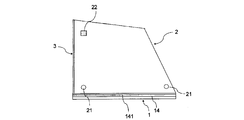
- FIG. 1 shows a state in which the side window glass 2 is viewed from the back side when the molding 1 of Example 1 is sandwiched between the lower sides of the side window glass 2.
- the side window glass 2 sandwiching the molding 1 of Example 1 is provided with a side molding 3 on the side of the side window glass that is in contact with a door (not shown).
- locate pins are attached to two places on the lower side of the side window glass 2, and placed on one place on the upper side of the side window glass 2.
- the fastener 22 is bonded.
- the flange surface 41 of the side window glass mounting portion 4 of the automobile is provided with a positioning hole (not shown) for inserting the locate pin 22 at a position corresponding to the two locate pins 22 bonded to the side window glass 2 in advance.
- a fastener (not shown) is bonded to a position corresponding to the fastener 22 bonded to the side window glass 2.
- FIG. 3 is a cross-sectional view of the vicinity of the molding 1 showing a state in which the side window glass 2 sandwiching the molding 1 of the first embodiment is being bonded to the flange surface 41 of the side window glass mounting portion 4 of the automobile. .
- the dam rubber 5 is placed on the back surface of the side window glass 2 along the periphery of the side window glass 2.
- the partial window glass 2 is made to wrap around and attached with a double-sided tape 8. Further, a primer is applied along the periphery outside the dam rubber 5 on the back surface of the side window glass 2 to form a primer coating layer 72 of the side window glass.
- a brush or felt cloth is used in the area sandwiched between the dam rubber 5 and the molding back side member 14.
- a primer is applied to form a primer coating layer 72 for the side window glass.
- a primer is also applied to the primer application surface 142 provided on the upper surface of the molding back side member 14.
- the primer coating layer 72 on the lower side of the back surface of the side window glass 2 is close to the primer coating surface 142 provided on the molding back side member 14 as shown in FIG.
- the primer When the primer is applied to the surface on the back side of the lower side of the part window glass, it can be applied so that the brush or the felt cloth also contacts the primer application surface 142 at the same time, and the working efficiency can be increased.
- a primer is applied to the flange surface 41 of the side window glass mounting portion 4 of the automobile at a position corresponding to the primer coating layer 72 of the side window glass, and the primer application of the side window glass mounting portion of the automobile is applied.
- Layer 71 is formed.
- the urethane adhesive 6 is applied on the primer coating layer 72 of the side window glass so as to go around the periphery of the side window glass 2.
- the locating pin 21 and the fastener 22 bonded to the side window glass 2 are respectively fitted with the flanges of the side window glass mounting portion 4 of the automobile so as to match the positions of the locator pin 21 and the fastener 22 bonded to the side window glass 2. Positioning is performed so as to match the positioning hole and fastener for inserting the locating pin provided on the surface 41, and the side window glass 2 is pressed against the flange surface 41 of the side window glass mounting portion 4 of the automobile to be bonded.
- FIG. 2 is a cross-sectional view showing a state in the vicinity of the molding 1 when the side window glass 2 is bonded to the flange surface 41 of the mounting part 4 of the side window glass of the automobile.
- the urethane adhesive 6 is pushed and spread by the side window glass 2 to the flange surface 41 of the side window glass mounting part 4 of the automobile, and a part of the urethane adhesive 6 is provided on the molding back side member 14.
- the adhesive portion 61 enters the adhesive entering groove 141 and enters the adhesive entering groove.
- the urethane adhesive 6 is also adhered to the primer application surface 142 of the molding back side member 14.
- the molding 1 is caught by the adhesive 61 that has entered the adhesive entering groove 141 in the adhesive entering groove 141, so that the molding 1 is prevented from falling off the side window glass 2. Can do.
- the urethane adhesive 6 is bonded to the primer application surface 142, the molding 1 and the side window glass 2 are bonded together by the urethane adhesive 6, and the molding 1 does not fall off the side window glass 2. Can be.
- the flange surface 41 of the side window glass mounting portion 4 of the automobile is formed in a deep place, and the window frame surface 42 is gently inclined from the vehicle body surface to the flange surface 41.
- the vehicle body contact lip 13 contacts the window frame surface 42, and the molding 1 is connected to the side window. Since it is sandwiched between the glass 2 and the window frame surface 42, an effect of suppressing the dropping of the molding 1 from the side window glass 2 to some extent can be expected.
- FIG. 5 is a view showing a state when the side window glass 2 is viewed from the back side when the molding 1 of Example 2 is sandwiched between the lower sides of the side window glass 2.
- the molding 1 of Example 2 has a configuration in which a plurality of molding clips 16 are attached to a molding body 17 made of stainless steel so that the molding clips 16 are not detached from the molding body 17.
- FIG. 6 shows a state where the side window glass 2 to which the molding 1 of Example 2 is attached is adhered to the side window glass mounting part 4 of the automobile, in a place where the molding clip 16 of the molding 1 is installed. It is sectional drawing.
- the molding 1 of Example 2 includes a stainless steel molding main body 1 provided with a vehicle body abutting lip 13, and a plurality of molding clips 16 are attached thereto.
- a molding back side member 14 is provided on the molding clip 16.
- the molding back side member 14 is provided with an adhesive entering groove 141, and the opening surface of the adhesive entering groove 141 faces the flange surface 41 of the side window glass mounting portion 4 of the automobile.
- the window glass sandwiching portion 12 of the mall 1 is a region sandwiched between the resin seal portion 18 provided at the tip of the molding body 17 and the molding back side member 14. Since an elastic means such as a spring (not shown) is attached to the surface of the molding back side member 14 facing the side window glass 2, the molding 1 is pressed against the seal portion 18 by the elastic means. The glass 2 is firmly attached to the lower side.
- an elastic means such as a spring (not shown) is attached to the surface of the molding back side member 14 facing the side window glass 2
- the glass 2 is firmly attached to the lower side.
- the side window glass 2 when the side window glass 2 is bonded to the flange surface 41 of the side window glass mounting portion 4 of the automobile, the side window glass 2 is attached to the flange of the side window glass mounting section 4 of the automobile. Since it is pressed against the surface 41, the urethane adhesive 6 is pushed and spreads by the side window glass 2 to the flange surface 41 of the side window glass mounting portion 4 of the automobile, and a part thereof enters the adhesive.
- the adhesive portion 61 that enters the groove 141 and enters the adhesive entering groove is formed.
- the molding 1 is caught by the adhesive 61 that has entered the adhesive entering groove 141 in the adhesive entering groove 141, so that the molding 1 is prevented from falling off the side window glass 2. Can do.
- the flange surface 41 of the side window glass mounting portion 4 of the automobile is formed in a deep place, and a step is formed as a window frame surface 42 from the vehicle body surface to the flange surface 41.
- the mall 1 according to the second embodiment includes the adhesive entering groove 141 on the molding back side member 14 provided on the molding clip 16 mounted on the molding 1. Therefore, compared with the case where the adhesive entering groove 141 is provided in the entire length direction of the molding 1 as in the first embodiment, the force for hooking the molding 1 with the adhesive entering groove 141 in the molding 1 of the second embodiment. Becomes weaker. However, even the configuration of the second embodiment can be used without any practical problem.
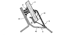
- FIG. 7 shows a conventional example when the side window glass 2 sandwiched with the molding 9 of the conventional example shown in Patent Document 2 is bonded to the flange surface 41 of the mounting part 4 of the side window glass of the automobile. It is sectional drawing which showed the mode of the mall 9 vicinity.
- the molding 9 of the conventional example is sandwiched between the projecting portion 91 provided on the front side of the molding 9 of the conventional example and the clamping piece 92 provided on the back side of the molding 9 of the conventional example.
- the molding back side member 14 provided with the adhesive entering groove 141 as shown by the molding 1 of the present invention is not provided.
Landscapes
- Engineering & Computer Science (AREA)
- Mechanical Engineering (AREA)
- Manufacturing & Machinery (AREA)
- Chemical & Material Sciences (AREA)
- Combustion & Propulsion (AREA)
- Transportation (AREA)
- Vehicle Interior And Exterior Ornaments, Soundproofing, And Insulation (AREA)
- Connection Of Plates (AREA)
Abstract
開示されているのは、自動車の側部窓ガラスの下辺を挟着する窓ガラス挟着部を有するモールであり、前記モールの自動車の側部窓ガラス装着部のフランジ面側に、溝を設けたモール裏側部材が備えられており、前記溝の開口面が、前記自動車の側部窓ガラス装着部のフランジ面と向き合うようにしているモールである。このモールは、少ない部品点数で構成でき、前記側部窓ガラスからの脱落を防止できるモールである。
Description
本発明は、自動車の側部窓ガラス装着部に固定される側部窓ガラスの下辺に挟着されるモールと、そのモールを挟着された側部窓ガラスの自動車の側部窓ガラス装着部への取付方法に関するものである。
自動車の側部窓ガラス装着部に固定されている側部窓ガラスには、その周辺部にモールが取付けられている場合がある。窓ガラス周辺部を挟着するモールとしては、モール本体と、前記モール本体に装着されるモール装着部を有する複数の前記モール本体に対してスライド自在のモールクリップとで前記側部窓ガラスの周辺部を挟着するモール(特許文献1)や、図7に示すような前記側部窓ガラスの車外側に当接される突成形部と前記側部窓ガラスの車内面側に当接される挟持片とを一体的に成形しており、前記突成形部と前記挟持片とで前記側部窓ガラスの下辺を挟着するモール(特許文献2)が提案されている。
特許文献1に記載の側部窓ガラスに挟着するモールでは、前記モールを挟着した前記側部窓ガラスと前記モールの前記モール本体に装着される複数のモールクリップの中の一部のモールクリップに前記モールを挟着した前記側部窓ガラスを前記自動車の側部窓ガラス装着部のフランジ面に位置決め及び仮止めをするためのロケートピンが備えられている。前記モールを挟着した前記側部窓ガラスを前記自動車の側部窓ガラス装着部の前記フランジ面に取付けるときには、前記側部窓ガラスの前記モールで挟着されている箇所よりも内側の周辺部に接着剤を塗布し、前記ロケートピンを前記側部窓ガラス装着部のフランジ面の所定の位置に設けた位置決め孔に嵌合する。
特許文献1の実施例で示されているモールでは、前記側部窓ガラスの上辺及び下辺を一体のモールで挟着している。仮に、特許文献1で記載されているモールが、前記側部窓ガラスの下辺のみを挟着するモールである場合、前記モールのモールクリップの一部にロケートピンが備えられているため、前記モールで挟着された側部窓ガラスを前記自動車の側部窓ガラス装着部の前記フランジ面に接着する際に、前記モールは前記自動車の側部窓ガラス装着部の前記フランジ面に仮止めされ、前記モールが車体から脱落することを防ぐことができる。
また、図7に示す特許文献2に記載の側部窓ガラスの下辺に挟着するモールでは、前記モールは、前記側部窓ガラスの下辺に挟着されているだけであり、前記自動車の側部窓ガラス装着部への固定と位置決めは、前記側部窓ガラスに備えられたボルトを、前記自動車の側部窓ガラス装着部の前記フランジ面の所定の位置に設けた位置決め孔に挿入し、ナットで前記ボルトを締め付けることで行う。そのため、前記側部窓ガラスを前記自動車の側部窓ガラス装着部へ取付けた後で、前記モールの位置決めを行う必要がなく、自動車組み立て時に作業を円滑に行うことができる。
しかしながら、特許文献1に記載のモールが前記側部窓ガラスの下辺のみを挟着するモールである場合、前記モールと前記側部窓ガラスの両方にロケートピンを備えているため、前記側部窓ガラスを前記自動車の側部窓ガラス装着部に取付けた後で、前記モールの位置が所定の位置からずれている場合に、前記モールの位置決めを行わなければならず、自動車組み立て時の作業工数を増やしてしまう問題があった。
また、特許文献2に記載のモールは、特許文献1に比べると、部品点数は少ないが、前記側部窓ガラスの下辺に挟着されているだけであるので、前記側部窓ガラスを前記自動車の側部窓ガラス装着部に取付けた後で、前記モールが、脱落してしまう可能性があった。
本発明は、これらの問題点の解決を図る。すなわち、自動車の側部窓ガラスの下辺に挟着されるモールについて、少ない部品点数で構成でき、自動車組み立て時の作業工数を増やすことなく、前記自動車の側部窓ガラス装着部に前記モールを挟着された側部窓ガラスを取付けた後で、前記側部窓ガラスからの脱落を防止できるモールを提供することを目的としている。
本発明に依れば、自動車の側部窓ガラスの下辺を挟着する窓ガラス挟着部を有するモールであり、前記モールの自動車の側部窓ガラス装着部のフランジ面側に、溝を設けたモール裏側部材が備えられており、前記溝の開口面が、前記自動車の側部窓ガラス装着部のフランジ面と向き合っていることを特徴とするモール(第1モール)が提供される。
第1モールは、前記モールの前記モール裏側部材の上面を、前記モールの長さ方向に延びる平坦な面として、前記平坦な面を前記側部窓ガラスと前記自動車の側部窓ガラス装着部の前記フランジ面とを接着する接着剤を接着させるためのプライマーを塗布するためのプライマー塗布面として用いることを特徴とする(第2モール)であってもよい。
第1又は第2モールは、前記モールの前記窓ガラス挟着部の入口付近を前記自動車の側部窓ガラス装着部のフランジ面側に折り曲げて傾斜させ、窓ガラス挟着部の傾斜部を設けたことを特徴とする第3モールであってもよい。
第1乃至第3モールのいずれか1つは、前記モールの前記窓ガラス挟着部の入口に、前記窓ガラス挟着部の内側に突出している窓ガラス当接リップを設けたことを特徴とする第4モールであってもよい。
本発明に依れば、第1乃至第4モールのいずれか1つで前記側部窓ガラスの下辺を挟着し、前記側部窓ガラスの周辺部にプライマーと接着剤を塗布し、前記側部窓ガラスを前記自動車の側部窓ガラス装着部のフランジ面に接着したときには、前記接着剤が前記側部窓ガラスと前記自動車の側部窓ガラス装着部の前記フランジ面に挟まれて、前記溝に前記接着剤が流れ込むように取付けることを特徴とする側部窓ガラスの取付方法が提供される。
また、本発明に依れば、第2乃至第4モールのいずれか1つで前記側部窓ガラスの下辺を挟着し、前記側部窓ガラスにプライマーを塗布するときに、同時に前記プライマー塗布面にもプライマーを塗布することを特徴とする側部窓ガラスの取付方法が提供される。
本発明の自動車のモールは、自動車の側部窓ガラスの下辺に挟着される窓ガラス挟着部を有するモールであり、前記モールの自動車の側部窓ガラス装着部側に、前記自動車の側部窓ガラス装着部のフランジ面に、その開口部が向き合う溝を備えたモール裏側部材を設けた。そのため、前記側部窓ガラスを前記自動車の側部窓ガラス装着部の前記フランジ面に接着した時には、前記側部窓ガラスの下辺に挟着されたモールの上部に塗布された接着剤が、前記自動車の側部窓ガラス装着部の前記フランジ面に押付けられて、前記接着剤の一部が、前記溝に流れ込む。そして、前記溝に流れ込んだ接着剤が固まると、その固まった接着剤が、前記溝に引っ掛かり、前記モールが、前記側部窓ガラスから脱落するのを防ぐことができる。
<本発明のモールの構成>
本発明のモールは、例えば図1のモール1のように側部窓ガラス2の下辺に挟着している。そして、図1のモール1付近での断面を示したものが、図2及び図3である。
本発明のモールは、例えば図1のモール1のように側部窓ガラス2の下辺に挟着している。そして、図1のモール1付近での断面を示したものが、図2及び図3である。
図2に示されるように、本発明のモール1は、側部窓ガラス2の下辺に挟着している。ここで、モール1を側部窓ガラス2の下辺に挟着したときに、側部窓ガラス2の、自動車の側部窓ガラス装着部4のフランジ面41側をモール1の裏側と呼び、その反対側をモール1の表側と呼ぶこととする。
本発明のモール1は、例えば、ステンレス鋼などの金属材料で構成される金属製芯材11と、金属製芯材11の一部がコの字状に折り曲げられた窓ガラス挟着部12を備えており、金属製芯材11を芯材とした複合押出成形により、モール1の裏側にモール裏側部材14を樹脂で形成し、モール1の表側に車体当接リップ13を樹脂で形成している。
窓ガラス挟着部12を形成する際に、窓ガラス挟着部12の入口付近を自動車の側部窓ガラス装着部4のフランジ面41側に折り曲げ、窓ガラス挟着部の傾斜部121としてもよい。
モール1の裏側においては、モール裏側部材14には、接着剤入り込み溝141を設けており、接着剤入り込み溝141の開口面は、自動車の側部窓ガラス装着部4のフランジ面41と向き合っている。そして、モールの長さ方向に沿って、その上面を平坦にしておき、プライマー塗布面142としてもよい。
モール1の表側には、金属製芯材11の先端部に車体当接リップ13を設けている。そして、窓ガラス挟着部12の入口に窓ガラス挟着部12の内側に突出するように窓ガラス当接リップ15を設けてもよい。
<本発明のモールに側部窓ガラスの下辺を挿入するとき>
図4は、本発明のモール1に側部窓ガラス2の下辺を窓ガラス挟着部12に挿入するときの様子を示したモール1と側部窓ガラス2の断面図である。このとき、窓ガラス挟着部12には、その入口に窓ガラス挟着部の傾斜部121が形成されているため、側部窓ガラス2を窓ガラス挟着部12に挿入するときに、円滑に窓ガラス挟着部12に挿入することができる。
図4は、本発明のモール1に側部窓ガラス2の下辺を窓ガラス挟着部12に挿入するときの様子を示したモール1と側部窓ガラス2の断面図である。このとき、窓ガラス挟着部12には、その入口に窓ガラス挟着部の傾斜部121が形成されているため、側部窓ガラス2を窓ガラス挟着部12に挿入するときに、円滑に窓ガラス挟着部12に挿入することができる。
窓ガラス挟着部12の幅は、少なくとも一部においては、側部窓ガラス2の厚さよりも少し狭くなるように形成されている。そのため、窓ガラス挟着部12の入口の表側に窓ガラス当接リップ15を設けていない場合には、側部窓ガラス2の下辺を窓ガラス挟着部12で挟着したときに、窓ガラスの挟着部の入口は広がってしまい、側部窓ガラス2と窓ガラス挟着部12の入口の表側との間に隙間が生じてしまう。そのため、前記隙間にチリや埃が入る不具合や、前記隙間そのものが見栄えを損なってしまうという不具合を生じてしまう。
そこで、窓ガラス当接リップ15を窓ガラス挟着部12の入口の表側に設けた場合、窓ガラス挟着部12の内側に突出して設けられているため、側部窓ガラス2を窓ガラス挟着部12に挿入したときに、窓ガラス当接リップ15が、側部窓ガラス2の表側に当接する。そのため、窓ガラス当接リップ15を設けることによって、側部窓ガラス2と窓ガラス挟着部12の入口の表側との間に生じる隙間に、前記隙間にチリや埃が入る不具合や、前記隙間の存在が側部窓ガラス2を自動車の側部窓ガラス装着部4に取付けたときの見栄えを損なってしまうという不具合を生じないようにすることができる。
<本発明のモールを挟着した側部窓ガラスの自動車の側部窓ガラス装着部のフランジ面への接着方法>
図3は、本発明のモール1を挟着した側部窓ガラス2を自動車の側部窓ガラス装着部4のフランジ面41に接着させるときの様子を示すモール付近の断面図である。
図3は、本発明のモール1を挟着した側部窓ガラス2を自動車の側部窓ガラス装着部4のフランジ面41に接着させるときの様子を示すモール付近の断面図である。
側部窓ガラス2を接着させるときには、予め、側部窓ガラスの周辺部にダムラバー5を両面テープ8で貼り付け、側部窓ガラス2のダムラバー5の外側の周辺部にプライマーを塗り、側部窓ガラスのプライマー塗布層72を形成し、プライマー塗布層上にウレタン接着剤を側部窓ガラス2の周辺部に沿って塗布する。側部窓ガラス2の下辺のモール1が挟着されている領域においては、側部窓ガラスのプライマー塗布層72をモール1とダムラバー5とに挟まれる領域に設けている。また、自動車の側部窓ガラス装着部4のフランジ面41にも、側部窓ガラスのプライマー塗布層72に合うようにプライマーを塗布し、車体側部窓ガラス装着部のプライマー塗布層71を形成する。
図3のようにモール裏側部材14の上面にモール1の長さ方向に平坦な面を形成している場合、それをプライマー塗布面142として利用することができ、プライマー塗布面142上にプライマーを塗布し、モールのプライマー塗布層73を形成することができる。プライマーは、はけやフェルトなどの布にしみ込ませて塗布するため、幅広にプライマーを塗布することができる。そのため、側部窓ガラスのプライマー塗布層72が、プライマー塗布面142の近くになるように設定すると、側部窓ガラス2とプライマー塗布面142に同時にプライマーを塗布することができ、自動車の組立工程において、側部窓ガラス2の自動車の側部窓ガラス装着部4への取付作業を効率よく行うことができるようになる。
図2に示すように、プライマー塗布面142にプライマー塗布層73を形成しておくと、側部窓ガラス2を自動車の側部窓ガラス装着部4のフランジ面へ接着したときに、プライマー塗布面142にもウレタン接着剤6が接着する。そのため、側部窓ガラス2とモール1とがウレタン接着剤6によって接着されることになるため、モール1が側部窓ガラス2から脱落することを防ぐことができる。
また、図2から、側部窓ガラス2を自動車の側部窓ガラス装着部4のフランジ面41に装着したとき、ウレタン接着剤6が、側部窓ガラス2と自動車の側部窓ガラス装着部4のフランジ面41とで挟まれるため、上下に広がり、その一部が、モール1のモール裏側部14に設けられた接着剤入り込み溝141に入り込み、接着剤入り込み溝に入り込んだ接着剤部61を形成する。接着剤入り込み溝に入り込んだ接着剤部61が固まると、モール1は、接着剤入り込み溝141で接着剤入り込み溝に入り込んだ接着剤部61に引っ掛かるため、モール1の側部窓ガラス2からの脱落を防ぐことができる。
さらにまた、図2に示すように、自動車の側部窓ガラス装着部4のフランジ面41は、奥まったところに形成されており、車体表面からフランジ面41まではゆるやかな傾斜や段差で構成される窓枠面42となっている。側部窓ガラス2を自動車の側部窓ガラス装着部4の所定の位置に接着したとき、車体当接リップ13が、窓枠面42に当接し、モール1が、側部窓ガラス2と窓枠面42との間に挟まるので、モール1の側部窓ガラス2からの脱落をある程度抑える効果が期待できる。
本発明のモールは、図1~図4のように、押出成形によって窓ガラス挟着部12、接着剤入り込み溝141を備えたモール裏側部材14などを一括して成形しているが、図5、図6のように、モール本体17に、接着剤入り込み溝14を備えたモール裏側部材14を設けたモールクリップ16を複数個装着することによって、図1~図4のモール1と同様の効果を得ることができる。
また、本発明のモールを押出成形で製作する場合には、図1~図4のように金属芯材11をステンレス鋼などの金属で形成し、その他の構成要素を複合押出成形によって樹脂で形成することが一般的だが、本モールを全て樹脂で成形することも可能である。
以下に本発明の各実施例について説明する。
<実施例1>
[実施例1のモールの構成]
図4は、本発明の実施例1のモールに、側部窓ガラス2を挿入しようとしている様子を示した断面図である。
[実施例1のモールの構成]
図4は、本発明の実施例1のモールに、側部窓ガラス2を挿入しようとしている様子を示した断面図である。
図4より、本発明のモール1は、ステンレス製の金属材料で構成される金属製芯材11と、金属製芯材11の一部がコの字状に折り曲げられた窓ガラス挟着部12を備えており、さらに、窓ガラス挟着部12の入口付近を自動車の側部窓ガラス装着部4側に折り曲げ、窓ガラス挟着部の傾斜部121としている。
そして、金属製芯材11を芯材として、複合押出成形により、車体当接リップ13と、モール裏側部材14と、窓ガラス当接リップとが樹脂で形成されている。そして、モール裏側部材14には、接着剤入り込み溝141と、プライマー塗布面142とが備えられている。
車体当接リップ13は、モール1の表側の金属製芯材11の先端部に設けられている。また、窓ガラス当接リップ15は、モール1の表側の窓ガラス挟着部12の入口に、窓ガラス挟着部12の内側に突出するように設けられている。
モール裏側部材14は、モール1の裏側に設けられている。モール裏側部材14に備えられている接着剤入り込み溝141の開口面は、自動車の側部窓ガラス装着部4のフランジ面41に向き合っている。また、モール裏側部材14に備えられているプライマー塗布面142は、モールの長さ方向に沿って、モール裏側部材14の上面を平坦にしたものである。
[実施例1のモールを側部窓ガラスに挟着させる方法]
モール1の窓ガラス挟着部12に、側部窓ガラス2の下辺を挟着させるときには、図4のように、側部窓ガラス2の下辺を、窓ガラス挟着部の傾斜部121に当接させて、窓ガラス挟着部の傾斜部121に沿って、窓ガラス挟着部12に挿入するようにするとよい。実施例1のモール1では、窓ガラス挟着部の傾斜部121を備えているため、側部窓ガラス2を円滑に窓ガラス挟着部12に挿入することができる。
モール1の窓ガラス挟着部12に、側部窓ガラス2の下辺を挟着させるときには、図4のように、側部窓ガラス2の下辺を、窓ガラス挟着部の傾斜部121に当接させて、窓ガラス挟着部の傾斜部121に沿って、窓ガラス挟着部12に挿入するようにするとよい。実施例1のモール1では、窓ガラス挟着部の傾斜部121を備えているため、側部窓ガラス2を円滑に窓ガラス挟着部12に挿入することができる。
窓ガラス挟着部12の幅は、少なくとも一部では、側部窓ガラス2の厚さよりも狭くなっている。そのため、側部窓ガラス2を窓ガラス挟着部12に挿入したときには、窓ガラス挟着部12の入口の幅が広がってしまう。実施例1のモール1においては、窓ガラス挟着部12の入口の表側に、窓ガラス当接リップ15を窓ガラス挟着部12の内側に突出するように設けているため、上記のように窓ガラス挟着部12の入口の幅が広がってしまっても、側部窓ガラス2の表面に、窓ガラス当接リップ15が当接することになる。そのため、窓ガラス当接リップ15が設けられることにより、側部窓ガラス2を窓ガラス挟着部12に挿入したことで、窓ガラス挟着部12の入口の幅が広がり、側部窓ガラスの表面と窓ガラス挟着部12との間に隙間が生じるのを防ぐことができる。
[側部窓ガラスを自動車の側部窓ガラス装着部のフランジ面に接着する方法]
図1は、側部窓ガラス2の下辺に実施例1のモール1を挟着したときの側部窓ガラス2を裏側から見た様子を示したものである。実施例1のモール1を挟着した側部窓ガラス2は、図示していないドアと接する側部窓ガラスの側辺に側辺モール3を設けており、さらに、側部窓ガラス2を自動車の側部窓ガラス装着部4に取付ける際に、位置決めを円滑に行うために、側部窓ガラス2の下辺部の2箇所にロケートピンを接着し、側部窓ガラス2の上辺部の一箇所にファスナー22を接着している。そして、自動車の側部窓ガラス装着部4のフランジ面41には、予め側部窓ガラス2に接着した2箇所のロケートピン22に対応した位置にロケートピン22を挿入するための図示しない位置決め孔を設けてあり、さらに、側部窓ガラス2に接着されているファスナー22に対応した位置に図示しないファスナーを接着させている。
図1は、側部窓ガラス2の下辺に実施例1のモール1を挟着したときの側部窓ガラス2を裏側から見た様子を示したものである。実施例1のモール1を挟着した側部窓ガラス2は、図示していないドアと接する側部窓ガラスの側辺に側辺モール3を設けており、さらに、側部窓ガラス2を自動車の側部窓ガラス装着部4に取付ける際に、位置決めを円滑に行うために、側部窓ガラス2の下辺部の2箇所にロケートピンを接着し、側部窓ガラス2の上辺部の一箇所にファスナー22を接着している。そして、自動車の側部窓ガラス装着部4のフランジ面41には、予め側部窓ガラス2に接着した2箇所のロケートピン22に対応した位置にロケートピン22を挿入するための図示しない位置決め孔を設けてあり、さらに、側部窓ガラス2に接着されているファスナー22に対応した位置に図示しないファスナーを接着させている。
図3は、実施例1のモール1を挟着した側部窓ガラス2を自動車の側部窓ガラス装着部4のフランジ面41に接着しようとしている様子を示したモール1付近の断面図である。側部窓ガラス2を自動車の側部窓ガラス装着部4のフランジ面41に接着する際には、まず側部窓ガラス2の裏面にダムラバー5を側部窓ガラス2の周辺に沿って、側部窓ガラス2を一周させて、両面テープ8で貼り付ける。また、側部窓ガラス2の裏面のダムラバー5よりも外側の周辺に沿って、プライマーを塗布し、側部窓ガラスのプライマー塗布層72を形成する。
モール1を挟着している側部ガラス2の下辺においては、側部窓ガラス2の裏面には、ダムラバー5とモール裏側部材14との間に挟まれた領域にはけやフェルト布を用いてプライマーを塗布して、側部窓ガラスのプライマー塗布層72とする。また、モール裏側部材14の上面に設けているプライマー塗布面142にもプライマーを塗布する。
図3のように側部窓ガラス2の裏面の下辺のプライマー塗布層72の位置を、モール裏側部材14に設けたプライマー塗布面142の近くにしておくと、はけやフェルト布を用いて側部窓ガラスの下辺の裏側の面にプライマーを塗布する際に、同時にはけやフェルト布がプライマー塗布面142にも接触するように塗布することができ、作業効率を上げることができる。
また、自動車の側部窓ガラス装着部4のフランジ面41にも、側部窓ガラスのプライマー塗布層72に対応した位置に、プライマーを塗布して、自動車の側部窓ガラス装着部のプライマー塗布層71を形成しておく。
そして、図3のように側部窓ガラスのプライマー塗布層72上にウレタン接着剤6を側部窓ガラス2の周辺部を一周するように塗布する。
そして側部窓ガラス2に接着されているロケートピン21及びファスナー22がそれぞれ、側部窓ガラス2に接着したロケータピン21及びファスナー22の位置に合うように自動車の側部窓ガラス装着部4のフランジ面41に設けたロケートピンを挿入するための位置決め孔及びファスナーに合うように位置決めし、側部窓ガラス2を自動車の側部窓ガラス装着部4のフランジ面41に押付けて、接着させる。
図2は、側部窓ガラス2を自動車の側部窓ガラスの装着部4のフランジ面41に接着させたときのモール1付近の様子を示した断面図である。図2においては、ウレタン接着剤6が、側部窓ガラス2によって、自動車の側部窓ガラス装着部4のフランジ面41に押されて広がり、その一部が、モール裏側部材14に備えられた接着剤入り込み溝141に入り込み、接着剤入り込み溝に入り込んだ接着剤部61を形成している。また、モール裏側部材14のプライマー塗布面142にも、ウレタン接着剤6が接着している。
ウレタン接着剤6が固まると、モール1は、接着剤入り込み溝141で接着剤入り込み溝に入り込んだ接着剤部61に引っ掛かることになるため、モール1の側部窓ガラス2からの脱落を防ぐことができる。
また、プライマー塗布面142にウレタン接着剤6が接着されているため、モール1と側部窓ガラス2とがウレタン接着剤6によって接着されることとなり、モール1が側部窓ガラス2から脱落しないようにすることができる。
さらにまた、自動車の側部窓ガラス装着部4のフランジ面41は、奥まったところに形成されており、車体表面からフランジ面41までは窓枠面42としてゆるやかな傾斜となっている。側部窓ガラス2を自動車の側部窓ガラス装着部4のフランジ面41の所定の位置に接着したとき、車体当接リップ13が、窓枠面42に当接し、モール1が、側部窓ガラス2と窓枠面42との間に挟まるので、モール1の側部窓ガラス2からの脱落をある程度抑える効果が期待できる。
<実施例2>
図5は、側部窓ガラス2の下辺に実施例2のモール1を挟着したときの側部窓ガラス2を裏側から見たときの様子を示した図である。
図5は、側部窓ガラス2の下辺に実施例2のモール1を挟着したときの側部窓ガラス2を裏側から見たときの様子を示した図である。
実施例2のモール1は、ステンレス製のモール本体17に、複数のモールクリップ16をモール本体17から抜けないように装着した構成となっている。
図6は、実施例2のモール1を装着した側部窓ガラス2を自動車の側部窓ガラス装着部4に接着したときの様子を示す、モール1のモールクリップ16が装着されている箇所の断面図である。
実施例2のモール1は、車体当接リップ13を設けたステンレス製のモール本体1を備えており、複数のモールクリップ16が装着されている。モールクリップ16には、モール裏側部材14が設けられている。モール裏側部材14には、接着剤入り込み溝141が備えられており、接着剤入り込み溝141の開口面は、自動車の側部窓ガラス装着部4のフランジ面41に向き合っている。
モール1の窓ガラス挟着部12は、モール本体17の先端部に設けた樹脂製のシール部18と、モール裏側部材14とで挟まれる領域となる。モール裏側部材14の側部窓ガラス2と対向する面には図示しないバネなどの弾性手段が取付けられているため、モール1は、前記弾性手段によって、シール部18に押付けられるため、側部窓ガラス2の下辺にしっかりと挟着される。
実施例2のモール1を挟着した側部窓ガラス2を自動車の側部窓ガラス装着部4のフランジ面41に接着する方法は、実施例1に示した接着方法と同様である。
図6に示すように、側部窓ガラス2を自動車の側部窓ガラス装着部4のフランジ面41に接着させる際には、側部窓ガラス2を自動車の側部窓ガラス装着部4のフランジ面41に押付けることとなるため、ウレタン接着剤6が、側部窓ガラス2によって、自動車の側部窓ガラス装着部4のフランジ面41に押されて広がり、その一部が、接着剤入り込み溝141に入り込み、接着剤入り込み溝に入り込んだ接着剤部61が形成されることになる。
ウレタン接着剤6が固まると、モール1は、接着剤入り込み溝141で接着剤入り込み溝に入り込んだ接着剤部61に引っ掛かることになるため、モール1の側部窓ガラス2からの脱落を防ぐことができる。
さらに、自動車の側部窓ガラス装着部4のフランジ面41は、奥まったところに形成されており、車体表面からフランジ面41までは窓枠面42として段差が形成されている。側部窓ガラス2を自動車の側部窓ガラス装着部4のフランジ面41の所定の位置に接着したとき、車体当接リップ13が、窓枠面42に当接し、モール1が、側部窓ガラス2と窓枠面42との間に挟まるので、モール1の側部窓ガラス2からの脱落をある程度抑える効果が期待できる。
実施例2のモール1は、モール1に複数装着されたモールクリップ16に設けられたモール裏側部材14に接着剤入り込み溝141を備えることになる。そのため、実施例1のようにモール1の長さ方向の全体に接着剤入り込み溝141を設けている場合に比べて、実施例2のモール1では、モール1を接着剤入り込み溝141で引っ掛ける力が弱くなる。しかしながら、実施例2のような構成であっても実用上問題なく用いることが可能である。
以上好適な実施の形態について述べたが、本発明はこれに限定されるものではなく種々の応用が考えられるものである。
<従来例>
図7は、特許文献2に示されている従来例のモール9が挟着された側部窓ガラス2を自動車の側部窓ガラスの装着部4のフランジ面41に接着させたときの従来例のモール9付近の様子を示した断面図である。
図7は、特許文献2に示されている従来例のモール9が挟着された側部窓ガラス2を自動車の側部窓ガラスの装着部4のフランジ面41に接着させたときの従来例のモール9付近の様子を示した断面図である。
従来例のモール9は、側部窓ガラス2の下辺を従来例のモール9の表側に設けられた突成形部91と、従来例のモール9の裏側に設けられた挟持片92とで挟着されているのみであり、本発明のモール1で示されるような接着剤入り込み溝141を備えたモール裏側部材14は備えていない。
1 モール
11 金属製芯材
12 窓ガラス挟着部
121 窓ガラス挟着部の傾斜部
13 車体当接リップ
14 モール裏側部材
141 接着剤入り込み溝
142 プライマー塗布面
15 窓ガラス当接リップ
16 モールクリップ
17 モール本体
2 側部窓ガラス
21 ロケートピン
22 ファスナー
3 側辺モール
4 自動車の側部窓ガラス装着部
41 フランジ面
42 窓枠面
5 ダムラバー
6 ウレタン接着剤
61 接着剤入り込み溝に流れ込んだ接着剤
71 自動車の側部窓ガラス装着部のプライマー塗布層
72 側部窓ガラスのプライマー塗布層
73 モールのプライマー塗布層
8 両面テープ
9 従来例のモール
91 突成形部
92 挟持片
Claims (6)
- 自動車の側部窓ガラス(2)の下辺を挟着する窓ガラス挟着部(12)を有するモール(1)において、 前記モール(1)の自動車の側部窓ガラス装着部(4)のフランジ面(41)側に、溝(141)を設けたモール裏側部材(14)が備えられており、前記溝(141)の開口面が、前記自動車の側部窓ガラス装着部(4)のフランジ面(41)と向き合っていることを特徴とするモール。
- 前記モール(1)の前記モール裏側部材(14)の上面を、前記モールの長さ方向に延びる平坦な面(142)として、前記平坦な面(142)を前記側部窓ガラス(2)と前記自動車の側部窓ガラス装着部(4)の前記フランジ面(41)とを接着する接着剤(6)を接着させるためのプライマーを塗布するためのプライマー塗布面(142)として用いることを特徴とする請求項1に記載のモール。
- 前記モール(1)の前記窓ガラス挟着部(12)の入口付近を前記自動車の側部窓ガラス(2)の前記フランジ面(41)側に折り曲げて傾斜させ、窓ガラス挟着部の傾斜部(121)を設けたことを特徴とする請求項1又は2に記載のモール。
- 前記モール(1)の前記窓ガラス挟着部(12)の入口に、前記窓ガラス挟着部(12)の内側に突出している窓ガラス当接リップ(15)を設けたことを特徴とする請求項1乃至3のいずれか一つに記載のモール。
- 請求項1乃至4のいずれか一つに記載のモール(1)で前記側部窓ガラス(2)の下辺を挟着し、前記側部窓ガラス(2)の周辺部にプライマーと接着剤を塗布し、前記側部窓ガラス(2)を前記自動車の側部窓ガラス装着部(4)のフランジ面(41)に接着したときに、前記接着剤が前記側部窓ガラス(2)と前記自動車の側部窓ガラス装着部(4)の前記フランジ面(41)に挟まれて、前記溝(141)に前記接着剤が流れ込むことを特徴とする側部窓ガラスの取付方法。
- 請求項2乃至4のいずれかに記載のモール(1)で前記側部窓ガラス(2)の下辺を挟着し、前記側部窓ガラス(2)にプライマーを塗布するときに、同時に前記プライマー塗布面(142)にもプライマーを塗布することを特徴とする側部窓ガラスの取付方法。
Priority Applications (3)
| Application Number | Priority Date | Filing Date | Title |
|---|---|---|---|
| EP20120819425 EP2740620A4 (en) | 2011-08-02 | 2012-07-26 | RUBBER MOLDING FOR VEHICLE AND METHOD OF FASTENING LATERAL WINDOW WITH RUBBER MOLDING TIGHTENED THEREON |
| US14/236,440 US20140197663A1 (en) | 2011-08-02 | 2012-07-26 | Molding for Vehicle and Method for Attaching Side Window with Molding Clamped Thereon |
| CN201280037999.6A CN103732428A (zh) | 2011-08-02 | 2012-07-26 | 汽车的嵌条及夹装有该嵌条的侧部窗玻璃的安装方法 |
Applications Claiming Priority (2)
| Application Number | Priority Date | Filing Date | Title |
|---|---|---|---|
| JP2011-169295 | 2011-08-02 | ||
| JP2011169295A JP5966272B2 (ja) | 2011-08-02 | 2011-08-02 | 自動車のモール及びそのモールを挟着された側部窓ガラスの取付方法 |
Publications (1)
| Publication Number | Publication Date |
|---|---|
| WO2013018630A1 true WO2013018630A1 (ja) | 2013-02-07 |
Family
ID=47629155
Family Applications (1)
| Application Number | Title | Priority Date | Filing Date |
|---|---|---|---|
| PCT/JP2012/068907 WO2013018630A1 (ja) | 2011-08-02 | 2012-07-26 | 自動車のモール及びそのモールを挟着された側部窓ガラスの取付方法 |
Country Status (5)
| Country | Link |
|---|---|
| US (1) | US20140197663A1 (ja) |
| EP (1) | EP2740620A4 (ja) |
| JP (1) | JP5966272B2 (ja) |
| CN (1) | CN103732428A (ja) |
| WO (1) | WO2013018630A1 (ja) |
Cited By (1)
| Publication number | Priority date | Publication date | Assignee | Title |
|---|---|---|---|---|
| US20140054944A1 (en) * | 2012-08-23 | 2014-02-27 | Lear Corporation | Vehicle seat head restraint actuation |
Families Citing this family (3)
| Publication number | Priority date | Publication date | Assignee | Title |
|---|---|---|---|---|
| US9669882B2 (en) * | 2015-07-28 | 2017-06-06 | GM Global Technology Operations LLC | Panel sealing apparatus and a method of assembling the panel sealing apparatus |
| DE102015013974A1 (de) * | 2015-10-29 | 2017-05-04 | Henniges Automotive Gmbh & Co. Kg | Scheibenanordnung, insbesondere Karosserie-Scheibenanordnung |
| JP7397746B2 (ja) | 2020-04-14 | 2023-12-13 | 西川ゴム工業株式会社 | 自動車用モール |
Citations (8)
| Publication number | Priority date | Publication date | Assignee | Title |
|---|---|---|---|---|
| JPS5180816U (ja) * | 1974-12-23 | 1976-06-28 | ||
| JPS55106109U (ja) * | 1979-01-19 | 1980-07-24 | ||
| JPS61169716U (ja) | 1985-04-10 | 1986-10-21 | ||
| JPH0275210U (ja) * | 1988-11-25 | 1990-06-08 | ||
| JPH07172165A (ja) * | 1993-12-21 | 1995-07-11 | Toyoda Gosei Co Ltd | 車両用ウインドガラスのマウント構造 |
| JP2002347438A (ja) * | 2001-05-30 | 2002-12-04 | Nissan Motor Co Ltd | ウインドウパネルの取付構造 |
| JP2008080917A (ja) | 2006-09-27 | 2008-04-10 | Honda Motor Co Ltd | 窓ガラスとガラスモールの取付構造および取付方法 |
| WO2010050259A1 (ja) * | 2008-10-31 | 2010-05-06 | トヨタ車体株式会社 | 固定窓のウィンドウモール |
Family Cites Families (18)
| Publication number | Priority date | Publication date | Assignee | Title |
|---|---|---|---|---|
| JPS57110522A (en) * | 1980-12-29 | 1982-07-09 | Nissan Motor Co Ltd | Air hissing sound preventing device for vehicle |
| DE3332233A1 (de) * | 1983-09-07 | 1985-03-21 | Volkswagenwerk Ag, 3180 Wolfsburg | Fensterscheibenhalterung, insbesondere fuer eine kraftfahrzeug-fensterscheibe |
| DE3413003A1 (de) * | 1984-04-06 | 1985-10-17 | Bayerische Motoren Werke AG, 8000 München | Fahrzeugscheibe |
| US4905432A (en) * | 1988-03-03 | 1990-03-06 | Navistar International Transportation Corp. | Windshield glass and trim assembly and method for making same |
| US5039157A (en) * | 1989-12-14 | 1991-08-13 | Tokai Kogyo Kabushiki Kaisha | Windshield molding |
| IT1248759B (it) * | 1990-06-07 | 1995-01-27 | Alfa Lancia Spa | Cornice sovrastampata per l'incapsulamento di vetri di autoveicoli |
| DE4100631A1 (de) * | 1991-01-11 | 1992-07-16 | Ver Glaswerke Gmbh | Fuer die montage durch verklebung vorbereitete autoglasscheibe |
| JPH04115917U (ja) * | 1991-03-28 | 1992-10-15 | 東海興業株式会社 | 自動車の固定窓用モ−ル付窓材 |
| US5261721A (en) * | 1991-10-18 | 1993-11-16 | Donnelly Corporation | Vehicular window assembly with weather seal |
| DE4228881A1 (de) * | 1992-08-29 | 1994-03-03 | Henniges Gummi | Karosseriefenster |
| US5413397A (en) * | 1994-02-02 | 1995-05-09 | Gold; Peter N. | Automotive window assembly system |
| US5624148A (en) * | 1995-02-13 | 1997-04-29 | Creative Extruded Products, Inc. | Window trim molding |
| JPH08282267A (ja) * | 1995-04-12 | 1996-10-29 | Suzuki Motor Corp | 自動車用窓構造 |
| JP2002362250A (ja) * | 2001-06-01 | 2002-12-18 | Nippon Pop Rivets & Fasteners Ltd | モール取付装置及びモールクリップ |
| DE10141788B4 (de) * | 2001-08-25 | 2006-02-23 | Dr.Ing.H.C. F. Porsche Ag | Scheibenanordnung für ein Fahrzeug |
| US7147274B2 (en) * | 2004-09-03 | 2006-12-12 | Nissan Technical Center North America | Windshield spacer |
| JP4743761B2 (ja) * | 2005-12-14 | 2011-08-10 | ダイハツ工業株式会社 | 自動車の窓シール構造 |
| JP4957537B2 (ja) * | 2006-12-22 | 2012-06-20 | 旭硝子株式会社 | 仮止めクリップ及び仮止めクリップの製造方法並びに仮止めクリップ付き窓用板状体 |
-
2011
- 2011-08-02 JP JP2011169295A patent/JP5966272B2/ja active Active
-
2012
- 2012-07-26 WO PCT/JP2012/068907 patent/WO2013018630A1/ja active Application Filing
- 2012-07-26 CN CN201280037999.6A patent/CN103732428A/zh active Pending
- 2012-07-26 EP EP20120819425 patent/EP2740620A4/en not_active Withdrawn
- 2012-07-26 US US14/236,440 patent/US20140197663A1/en not_active Abandoned
Patent Citations (8)
| Publication number | Priority date | Publication date | Assignee | Title |
|---|---|---|---|---|
| JPS5180816U (ja) * | 1974-12-23 | 1976-06-28 | ||
| JPS55106109U (ja) * | 1979-01-19 | 1980-07-24 | ||
| JPS61169716U (ja) | 1985-04-10 | 1986-10-21 | ||
| JPH0275210U (ja) * | 1988-11-25 | 1990-06-08 | ||
| JPH07172165A (ja) * | 1993-12-21 | 1995-07-11 | Toyoda Gosei Co Ltd | 車両用ウインドガラスのマウント構造 |
| JP2002347438A (ja) * | 2001-05-30 | 2002-12-04 | Nissan Motor Co Ltd | ウインドウパネルの取付構造 |
| JP2008080917A (ja) | 2006-09-27 | 2008-04-10 | Honda Motor Co Ltd | 窓ガラスとガラスモールの取付構造および取付方法 |
| WO2010050259A1 (ja) * | 2008-10-31 | 2010-05-06 | トヨタ車体株式会社 | 固定窓のウィンドウモール |
Cited By (2)
| Publication number | Priority date | Publication date | Assignee | Title |
|---|---|---|---|---|
| US20140054944A1 (en) * | 2012-08-23 | 2014-02-27 | Lear Corporation | Vehicle seat head restraint actuation |
| US9145078B2 (en) * | 2012-08-23 | 2015-09-29 | Lear Corporation | Vehicle seat head restraint actuation |
Also Published As
| Publication number | Publication date |
|---|---|
| JP5966272B2 (ja) | 2016-08-10 |
| EP2740620A1 (en) | 2014-06-11 |
| JP2013032106A (ja) | 2013-02-14 |
| US20140197663A1 (en) | 2014-07-17 |
| CN103732428A (zh) | 2014-04-16 |
| EP2740620A4 (en) | 2015-03-04 |
Similar Documents
| Publication | Publication Date | Title |
|---|---|---|
| JP2011508700A (ja) | 窓ガラス構造 | |
| WO2013018630A1 (ja) | 自動車のモール及びそのモールを挟着された側部窓ガラスの取付方法 | |
| JPS62286827A (ja) | 板ガラス | |
| US9103155B2 (en) | Window pane fastening | |
| JP5929028B2 (ja) | 自動車のモール及びそのモールを取付けた側部窓ガラスの取付方法 | |
| US20180304822A1 (en) | Trim part with integrated antenna | |
| WO2018198959A1 (ja) | モール付きウインドシールドおよびカウルルーバとモール付きウインドシールドとの連接構造 | |
| JP6623974B2 (ja) | 車両用樹脂ウインドウパネルの固定構造 | |
| JP5472786B2 (ja) | 自動車ガラスにおける位置決め用スペーサーの接着方法 | |
| JP5020172B2 (ja) | ガラス仮固定用クリップ | |
| US6944917B2 (en) | Clip for mounting weatherstrip | |
| JPH10230738A (ja) | 車両窓およびこの車両窓の組立方法 | |
| JP5216756B2 (ja) | 車両用モールディングの連結構造 | |
| JP5755090B2 (ja) | 車両用のモール | |
| JP2002337550A (ja) | シール部品の取付構造 | |
| JP5474912B2 (ja) | 車両用窓板の装飾部材 | |
| US10596890B2 (en) | Pane assembly, in particular pane assembly for vehicle body | |
| JP4057490B2 (ja) | 自動車用スライドウインドガラスラン | |
| US11440378B2 (en) | Connection structure between windshield and cowl louver | |
| JP6686854B2 (ja) | モール取付用クリップ及びモールの取付構造 | |
| JP2009119966A (ja) | 車両用ドアサッシュ構造 | |
| JP2018001923A (ja) | 車両用モールディングの製造方法及び車両用モールディング | |
| JP2004001588A (ja) | ウェザーストリップの取付構造及び取付方法と、その製造方法 | |
| EP3785960A1 (en) | Vehicular belt moldings | |
| CN115817126A (zh) | 包边组件及其装配方法、车窗 |
Legal Events
| Date | Code | Title | Description |
|---|---|---|---|
| 121 | Ep: the epo has been informed by wipo that ep was designated in this application |
Ref document number: 12819425 Country of ref document: EP Kind code of ref document: A1 |
|
| WWE | Wipo information: entry into national phase |
Ref document number: 14236440 Country of ref document: US Ref document number: 2012819425 Country of ref document: EP |
|
| NENP | Non-entry into the national phase |
Ref country code: DE |