WO2013015257A1 - ステアリングコラムとその製造方法、およびこのステアリングコラムを用いたステアリング装置 - Google Patents
ステアリングコラムとその製造方法、およびこのステアリングコラムを用いたステアリング装置 Download PDFInfo
- Publication number
- WO2013015257A1 WO2013015257A1 PCT/JP2012/068627 JP2012068627W WO2013015257A1 WO 2013015257 A1 WO2013015257 A1 WO 2013015257A1 JP 2012068627 W JP2012068627 W JP 2012068627W WO 2013015257 A1 WO2013015257 A1 WO 2013015257A1
- Authority
- WO
- WIPO (PCT)
- Prior art keywords
- cylindrical member
- ring
- steering column
- main body
- inner diameter
- Prior art date
Links
Images


Classifications
-
- B—PERFORMING OPERATIONS; TRANSPORTING
- B22—CASTING; POWDER METALLURGY
- B22D—CASTING OF METALS; CASTING OF OTHER SUBSTANCES BY THE SAME PROCESSES OR DEVICES
- B22D19/00—Casting in, on, or around objects which form part of the product
- B22D19/04—Casting in, on, or around objects which form part of the product for joining parts
- B22D19/045—Casting in, on, or around objects which form part of the product for joining parts for joining tubes
-
- B—PERFORMING OPERATIONS; TRANSPORTING
- B22—CASTING; POWDER METALLURGY
- B22D—CASTING OF METALS; CASTING OF OTHER SUBSTANCES BY THE SAME PROCESSES OR DEVICES
- B22D19/00—Casting in, on, or around objects which form part of the product
- B22D19/16—Casting in, on, or around objects which form part of the product for making compound objects cast of two or more different metals, e.g. for making rolls for rolling mills
-
- B—PERFORMING OPERATIONS; TRANSPORTING
- B62—LAND VEHICLES FOR TRAVELLING OTHERWISE THAN ON RAILS
- B62D—MOTOR VEHICLES; TRAILERS
- B62D1/00—Steering controls, i.e. means for initiating a change of direction of the vehicle
- B62D1/02—Steering controls, i.e. means for initiating a change of direction of the vehicle vehicle-mounted
- B62D1/16—Steering columns
-
- B—PERFORMING OPERATIONS; TRANSPORTING
- B22—CASTING; POWDER METALLURGY
- B22D—CASTING OF METALS; CASTING OF OTHER SUBSTANCES BY THE SAME PROCESSES OR DEVICES
- B22D17/00—Pressure die casting or injection die casting, i.e. casting in which the metal is forced into a mould under high pressure
Definitions
- the present invention relates to a steering apparatus for an automobile, and more particularly, to a steering column constituting the steering apparatus and a method for manufacturing the same.
- a structure as shown in FIG. 27 is widely known as a steering device for giving a steering angle to a steered wheel (usually a front wheel except for a special vehicle such as a forklift).
- a steering shaft 3 is rotatably supported on the inner diameter side of a cylindrical steering column 2 supported by the vehicle body 1.
- a steering wheel 4 is fixed to a rear end portion of the steering shaft 3 protruding rearward from the rear end opening of the steering column 2.
- the steering wheel 4 is rotated, this rotation is transmitted to the input shaft 8 of the steering gear unit 7 via the steering shaft 3, the universal joint 5a, the intermediate shaft 6, and the universal joint 5b.
- the input shaft 8 rotates, a pair of tie rods 9 arranged on both sides of the steering gear unit 7 are pushed and pulled, and a steering angle corresponding to the operation amount of the steering wheel 4 is given to the pair of left and right steering wheels.
- a telescopic type is used as the steering column 2 and the steering shaft 3.
- a secondary collision in which the driver's body collides with the steering wheel 4 occurs following a primary collision in which the vehicle collides with another vehicle.
- a structure for protecting the driver by displacing the steering wheel 4 while absorbing energy is provided in the steering column 2 and the steering shaft 3.
- a structure is employed in which the steering shaft 3 that supports the steering wheel 4 is supported on the vehicle body 1 so as to be displaceable forward by a forward impact load accompanying a secondary collision.
- the steering shaft 3 is constituted by the outer tube 11 and the inner shaft so that the outer tube 11 can be displaced forward while reducing the overall length of the steering shaft 3 due to the impact load of the secondary collision.
- the steering column 2 that supports the steering shaft 3 is composed of an outer column 10 and an inner column, and the outer column 10 can be displaced forward while the entire length of the steering column 2 is reduced. Supports against.
- the front and rear positions of the outer column and the inner column that constitute such a telescopic steering column, and the outer tube and the inner shaft that constitute the steering shaft may be opposite to the illustrated structure.
- FIG. 28 shows a structure disclosed in Japanese Patent Laid-Open No. 2008-265646 as an example of a steering lock device.
- the steering lock device 12 is provided with a lock unit 13 in a part of the steering column 2a, and at a part of the steering shaft 3a at a position where the phase in the axial direction coincides with that of the lock unit 13 at least in one circumferential direction.
- a key lock collar 15 formed with a joint recess 14 is fitted and fixed.
- the distal end portion of the lock pin 16 constituting the lock unit 13 is inserted into the inner diameter side of the steering column 2a through the lock through hole 17 formed in the intermediate portion in the axial direction of the steering column 2a.
- the steering shaft 3a is substantially disabled from rotating by being displaced toward the engagement recess 14 and being engaged with the engagement recess 14.
- a lock unit 13 is provided on the outer diameter side of the steering column 2a, and a key lock collar 15 is provided on the inner diameter side of the steering column 2a.
- the key lock collar 15 is rotatably disposed on the inner diameter side of the steering column 2a, and the lock pin 16 and the key lock collar 15 are securely engaged and disengaged without excessively increasing the stroke of the lock pin 16. Therefore, it is necessary to reduce the thickness of the steering column 2a in this portion by reducing the outer diameter of the steering column 2a in which at least the steering lock device 12 is incorporated and increasing the inner diameter thereof.
- FIG. 29 shows an outer column 10a constituting a steering column disclosed in Japanese Patent Laid-Open No. 2007-223383.
- the other end of the cylindrical inner column is fitted into one end of the outer column 10a in the axial direction (the left end in FIG. 29) so as to be relatively displaceable in the axial direction.
- the outer column 10a is made of a light alloy such as an aluminum alloy or a magnesium alloy, and is integrally formed by casting.
- a lock for incorporating a steering lock device 12 as shown in FIG. A through-hole 17a for use is provided.
- the present invention has been made in view of the above circumstances, and an object thereof is to realize a structure capable of ensuring the strength of the steering column while reducing the thickness of a part of the cylindrical steering column.
- the steering column of the present invention has a cylindrical shape as a whole, and the whole or a part thereof is constituted by a column member.
- the column member is coupled in the axial direction by fitting a main body portion made of a light alloy such as an aluminum-based alloy or a magnesium-based alloy and an end portion on the other side to one end portion of the main body portion. It has a cylindrical member made of an iron-based alloy, and a metal ring that is fitted and fixed to the inner diameter side of the joint portion between the main body portion and the cylindrical member.
- One side means one side of the steering column in the axial direction, and the other side means the opposite side of the axial direction.
- the inner diameter of the ring is equal to or larger than the inner diameter of the portion of the main body portion that is axially removed from the coupling portion, and is equal to or smaller than the inner diameter of the cylindrical member.
- the ring is preferably made of a light alloy such as an aluminum alloy or a magnesium alloy.
- the column member has the other end portion of the cylindrical member fitted into one end portion of the main body portion, and the ring is connected to the main body portion. It has a structure that is fitted and fixed to the inner peripheral surface of the coupling portion with the cylindrical member.
- the ring is positioned in the axial direction so that one end edge of the main body portion is located radially outward of the axial intermediate portion of the ring.
- an outward flange-like flange portion protruding radially outward is provided at the other end portion of the ring, and one side surface of the flange portion is brought into contact with the other end surface of the cylindrical member. It is preferable.
- the other end portion of the cylindrical member is externally fitted to one end portion of the main body portion, and the ring is a connecting portion between the main body portion and the cylindrical member. It has the structure currently fitted and fixed to the inner peripheral surface.
- the column member has an outer diameter of the ring smaller than an inner diameter of a coupling portion between the main body portion and the cylindrical member, and the ring includes the main body portion and the cylindrical member.
- the inner portion is fixedly fitted with a gap between the outer peripheral surface of the ring and the inner peripheral surface of the other end portion of the cylindrical member.
- the steering column of the present invention is preferably used for a steering device provided with a steering lock device.
- the locking column that constitutes the steering lock device is provided at one position in the axial direction intermediate portion of the cylindrical member. A hole is provided.
- the method for manufacturing a steering column according to the present invention is characterized in that the column member is obtained by the following steps. That is, the step of fitting the ring into the other end portion of the cylindrical member, the other end portion of the cylindrical member is inserted into an insertion hole opened on one end surface of the mold, and this cylindrical shape A step of projecting the other end of the member into the mold, a step of inserting the one end of the core into the ring, a step of feeding a melt of light alloy into the mold and molding the main body portion
- the column member is obtained. Note that the order of these steps can be changed as long as no contradiction occurs.
- an inner diameter of the ring is smaller than an inner diameter of the main body portion, and an inner diameter of the cylindrical member is larger than an inner diameter of a portion of the main body portion that is axially removed from the coupling portion.
- the main body portion is molded, and after the main body portion is molded, the inner diameter side portion of the ring is subjected to a cutting process, and the inner diameter of the ring is set to a portion of the main body portion that is axially removed from the coupling portion.
- the method further includes the step of setting the inner diameter to be equal to or larger than the inner diameter and equal to or smaller than the inner diameter of the cylindrical member.
- the outer diameter of the ring is the inner diameter of the other end of the cylindrical member that serves as a joint between the main body portion and the cylindrical member.
- the ring is formed at the other end of the cylindrical member with a gap provided between the outer peripheral surface of the ring and the inner peripheral surface of the other end of the cylindrical member. Secure with internal fit.
- a mold having a stepped portion on the inner diameter side near the one side end is used as the mold, and the other end of the cylindrical member is protruded into the mold. Then, the step portion of the mold is positioned radially outward of the axial intermediate portion of the ring, and an edge of the main body portion is formed by feeding a part of the molten metal toward the step portion. To do.
- a ring having an outward flange-like flange projecting radially outward is provided at the other end as the ring, and the one end side surface of the flange is disposed on the cylindrical member. And the other end of the ring is also projected into the mold.
- a steering device is provided between a steering column supported by a vehicle body, a steering shaft rotatably supported on the inner diameter side of the steering column, and the steering column and the steering shaft. And a steering lock device that substantially prevents the shaft from rotating in the steering column.
- the steering column of the present invention is used as the steering column.
- the strength of the steering column can be secured while reducing the thickness of a part of the steering column. That is, since the portion near one end of the column member constituting the steering column is formed of a cylindrical member made of an iron-based alloy, even if the thickness near this one end is reduced, Strength can be secured. On the other hand, the portion near the other end of the column member is constituted by a main body portion made of a light alloy such as an aluminum alloy or a magnesium alloy, so that the weight of the entire steering column does not increase excessively.
- the inner diameter of the column member constituting the steering column can be increased in the order of the main body portion, the ring, and the cylindrical member. Furthermore, since the thin cylindrical member is not cut when the inner diameter of the joint portion between the main body portion and the cylindrical member is cut, it is possible to prevent the strength of the cylindrical member from being lowered. .
- the steering column of the present invention since the steering column of the present invention does not involve a complicated structure, it can be industrially produced efficiently and at low cost.
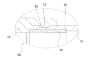
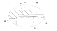
- FIG. 1 is a cross-sectional view of a column member of a steering column, showing a first example of an embodiment of the present invention.
- FIG. 2 is an enlarged view of part a in FIG.
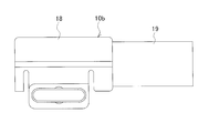
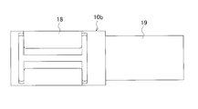
- FIG. 3 is a side view of the column member of the first example of the embodiment of the present invention.
- 4 is a view as seen from below in FIG.
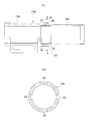
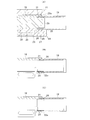
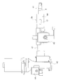
- FIG. 5 is a partial cross-sectional view showing the method for manufacturing the steering column in the first example of the embodiment of the present invention in the order of steps.
- FIG. 6 is a cross-sectional view for explaining a problem of the manufacturing method when no ring is used.
- FIG. 7A shows a second example of the embodiment of the present invention, and is a view similar to FIG. 1, and FIG.
- FIG. 7B is a cross-sectional view taken along line bb of FIG. 7A.
- FIG. 8 is a view similar to FIG. 1, showing a third example of the embodiment of the present invention.
- FIG. 9 is an enlarged view of part c of FIG.
- FIG. 10 is a view similar to FIG. 5 showing a third example of the embodiment of the present invention.
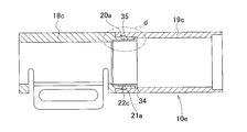
- FIG. 11 is a view similar to FIG. 1, showing a fourth example of the embodiment of the present invention.
- FIG. 12 is an enlarged view of a portion d in FIG.
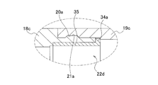
- FIG. 13 is a view similar to FIG. 1, showing a fifth example of the embodiment of the present invention.
- FIG. 14 is an enlarged view of part e in FIG.
- FIG. 15 is a view similar to FIG.
- FIG. 16 is an enlarged view of part f in FIG.
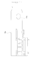
- FIG. 17 is a view similar to FIG. 5, showing a sixth example of the embodiment of the present invention.
- FIG. 18 is a view similar to FIG. 1, showing a seventh example of the embodiment of the present invention.
- FIG. 19 is an enlarged view of part g in FIG.
- FIG. 20 is a view similar to FIG. 5, showing a seventh example of the embodiment of the present invention.
- FIG. 21 is a view similar to FIG. 1, showing an eighth example of the embodiment of the present invention.
- FIG. 22 is an enlarged view of part h in FIG.
- FIG. 23 is a perspective view showing a cylindrical member taken out, showing an eighth example of the embodiment of the present invention.
- FIG. 24 is a view similar to FIG. 23, showing a ninth example of the embodiment of the present invention.
- FIG. 25 is a side view showing a steering apparatus according to a tenth example of the embodiment of the present invention.
- FIG. 26 is a plan view seen from above in FIG.
- FIG. 27 is a perspective view showing an example of a conventionally known steering device with a part thereof cut.
- FIG. 28 is a schematic cross-sectional view showing an example of a conventional structure of a steering lock device.
- FIG. 29 is a side view showing an example of a conventional structure of a steering column provided with a lock through hole.
- FIGS. 1 to 5 show a first example of an embodiment of the present invention.
- the steering column according to the present invention, including the present example, is characterized by reducing the thickness of the rear half (right side in FIGS. 1 to 5) of the outer column 10b, which is a column member constituting the steering column.
- the outer column 10b which is a column member constituting the steering column.
- it is in the point which industrially implement
- the outer column 10b is formed by axially connecting a main body portion 18 made of a light alloy such as an aluminum alloy or a magnesium alloy and a cylindrical member 19 made of an iron alloy such as a carbon steel plate. Composed. That is, the front end portion (the left side in FIGS. 1 to 5), which is the other end portion of the cylindrical member 19, is placed inside the rear end portion (the right side in FIGS. 1 to 5) that is one end portion of the main body portion 18. Fit and fix. Therefore, the main body portion 18 constitutes the front half of the outer column 10b, and the cylindrical member 19 constitutes the rear half of the outer column 10b.
- the main body portion 18 means a portion of the steering column or outer column 10b having a structure for supporting and fixing to the vehicle body.
- one side means one side in the axial direction of the steering column
- the other side means the opposite side in the axial direction
- the rear side of the vehicle body corresponds to one side
- the front side of the vehicle body corresponds to the other side.
- the cylindrical member when the cylindrical member is coupled in front of the main body portion, the vehicle body front side is one side and the vehicle body rear side is the other side.
- a structure in which a cylindrical member is coupled to both sides of the main body portion is also included in the present invention.
- a concave groove 20 is provided in a part of the outer peripheral surface of the front end portion of the cylindrical member 19 in the axial direction. Then, the main body portion 18 and the cylindrical member 19 are coupled in the axial direction by engaging the protrusion 21 provided on the inner peripheral surface of the rear end portion of the main body portion 18 in the concave groove 20.
- the entire inner circumferential surface of the front end portion of the cylindrical member 19 and the rear end portion of the main body portion 18, which is a connecting portion between the main body portion 18 and the cylindrical member 19, is entirely cylindrical.
- the ring 22 is internally fitted and fixed.
- the inner diameter of the ring 22 was removed from the connecting portion of the main body portion 18 and the cylindrical member 19 in the axial direction by cutting the inner peripheral surface of the ring 22.
- the inner diameter of the portion is greater than or equal to the inner diameter of the cylindrical member 19.
- bond part of the main-body part 18 and the cylindrical member 19 means the part which has overlapped with the cylindrical member 19 or the ring 22 among the rear-end parts of the main-body part 18 in the axial direction.
- the material of the ring 22 may be either a light alloy or an iron alloy, but is preferably made of a light alloy such as an aluminum alloy or a magnesium alloy.
- a light alloy such as an aluminum alloy or a magnesium alloy.
- the cost and time required for the work of cutting the inner peripheral surface of the ring 22 can be reduced compared to a case where the ring 22 is made of a relatively hard metal such as an iron-based alloy. .
- the cutting force can be made the same by making the main-body part 18 and the ring 22 from the same light alloy, a processing precision improves.
- the front end portion of the cylindrical member 19 is inserted into the insertion hole 25 opened in the outer side surface 24 which is one end surface of the mold 23 as shown in FIG. And it fits inside and the front-end part of the cylindrical member 19 is protruded in the metal mold
- FIG. The shape of the inner peripheral surface that defines the insertion hole 25 of the mold 23 matches the outer shape of the main body portion 18 obtained by the manufacturing method of this example.
- a ring 22 is fitted into the front end of the cylindrical member 19 in advance by an interference fit.
- the axial direction of the cylindrical member 19 is such that the ring 22 does not enter the inner side of the cylindrical member 19 (the right side in FIG. 5) and stops at an appropriate position.
- a step portion 26 is provided on the inner peripheral surface of the intermediate portion, and the inner diameter of the portion closer to the rear end than the step portion 26 is made smaller than the outer diameter of the ring 22.
- the stepped portion 27 provided on the inner peripheral surface of the mold 23 is positioned radially outward of the axially intermediate portion of the ring 22.
- the core 28 is inserted into the insertion hole 25 of the mold 23 from the other side (on the side opposite to the outer surface 24 in the axial direction), and the tip end portion 29 which is one side end of the core 28 is inserted into the ring 22. Insert and fit.
- the ring 22 is pressed toward the back side (stepped portion 26) of the cylindrical member 19 by the stepped surface 31 provided between the distal end portion 29 and the proximal end portion 30 of the core 28. Therefore, the internal space of the mold 23 is defined by the mold 23, the front end portion of the cylindrical member 19, the ring 22 and the core 28.
- a molten alloy of a light alloy such as an aluminum-based alloy or a magnesium-based alloy is fed into the mold 23, and pressure is applied to the mold 23 from above and below as indicated by arrows in FIG. Add. With this pressure, the internal space of the mold 23 is sealed, and the molten metal can be fed into the internal space of the mold 23 with sufficient pressure, whereby the main body portion 18 is molded. At this time, the molten metal enters the concave groove 20 of the cylindrical member 19, whereby the protrusion 21 is formed on the inner peripheral surface of the main body portion 18. Further, since the stepped portion 27 is positioned radially outward of the intermediate portion of the ring 22, the rear end edge (the right end edge in FIG. 5) of the main body portion 18 is radially outward of the axially intermediate portion of the ring 22. Formed in the direction.
- a light alloy such as an aluminum-based alloy or a magnesium-based alloy
- the inner diameter side portion of the ring 22 and the portion of the rear end portion of the main body portion 18 adjacent to the coupling portion is cut.
- the inner diameter of the ring 22 and the rear end portion of the main body portion 18 adjacent to the coupling portion is equal to the inner diameter of the portion of the main body portion 18 that is axially deviated from the coupling portion between the main body portion 18 and the cylindrical member 19.
- the inner diameter of the cylindrical member 19 is set to be equal to or smaller than the above.
- the coupling portion between the main body portion 18 and the cylindrical member 19 in the main body portion 18 is axially moved.
- Cutting can also be performed on the inner diameter side portion of the removed portion.
- the inner peripheral surface of the main body portion 18 through which the inner column is inserted can be made uniform, and the fitting force between the inner column and the main body portion 18 can be stabilized.
- cutting the inner diameter side portion of the rear end portion of the main body portion 18 adjacent to the coupling portion is convenient for ease of processing. It can be substantially evaluated that only the inner diameter side portion of 22 is cut.
- the strength can be secured while reducing the thickness of the rear half portion in which the steering lock device 12 (see FIG. 28) is incorporated in the outer column 10b constituting the steering column. That is, the latter half part of the outer column 10b is constituted by a cylindrical member 19 made of an iron-based alloy that is easy to ensure strength. For this reason, in order to attach the lock unit 13 or the key lock collar 15, the thickness of the cylindrical member 19 constituting the latter half is preferably about 0.4 to 0.75 times the thickness of the main body portion 18. Is about 0.5 to 0.7 times thinner, or even if the lock through hole 17 is provided for inserting the lock pin 16, the entire outer column 10b including the cylindrical member 19 is provided. Strength can be secured.
- the portion excluding the cylindrical member 19 (the main body portion 18 and the inner column in the outer column 10b) is made of a light alloy such as an aluminum alloy or a magnesium alloy. And since the thickness of the cylindrical member 19 is made thin, the weight of the whole steering column does not increase excessively.
- the shaft between the main body portion 18 and the cylindrical member 19 is engaged.
- the bonding strength in the direction can be secured.
- the sliding resistance can be increased and the coupling strength in the circumferential direction can be improved.
- the main body portion 18 and the cylinder are formed by forming irregularities extending in the circumferential direction on the bottom surface of the concave groove 20 and through holes that open to the bottom surface of the concave groove 20 and are closed by the ring 22 as necessary. It becomes possible to prevent relative rotation with the shaped member 19 more reliably.
- FIG. 6 shows that the main body portion 18a and the cylindrical member 19a are connected in the axial direction based on only the engagement between the groove 20 and the protrusion 21 without using the ring 22 (see FIGS. 1 to 5).
- the outer column 10c is manufactured by setting the inner diameter of the cylindrical member 19a to be equal to or larger than the inner diameter of the main body portion 18a in the portion axially deviated from the coupling portion between the main body portion 18a and the cylindrical member 19a.
- this mating surface is the end surface of the ring 22, whereas in the reference example, it is the end surface of the cylindrical member 19a.
- the inner peripheral surface of the rear end portion of the main body portion 18a is engaged with the outer peripheral surface of the front end portion of the cylindrical member 19a under such conditions as in the case of FIG.
- the main body portion 18a is formed by casting.
- the main body portion 18a and the cylindrical member 19a are cut.
- the thickness of the cylindrical member 19a is thin, if the inner diameter side portion is cut, the thickness of the cylindrical member 19a becomes excessively thin at the coupling portion, and the coupling strength of the coupling portion is ensured. Can not do it.
- the cutting is substantially performed on the inner diameter side portion of the ring 22 and the cylindrical member 19 is cut. It will never be done.
- the total thickness of the overlapping portion of the front end portion of the cylindrical member 19 and the ring 22 shown in FIGS. 5A and 5B is the cylindrical member 19a shown in FIG. It is sufficiently larger than the thickness of the front end portion. For this reason, as shown in FIG. 5C, the thickness of the overlapping portion can be sufficiently secured even when the ring 22 is cut, so that the strength of the joint portion between the main body portion 18 and the cylindrical member 19 is also increased. Enough can be secured.
- the inner diameter side portion of the ring 22 is cut, and the inner diameter of the ring 22 is equal to or larger than the inner diameter of the portion of the main body portion 18 that is axially deviated from the coupling portion between the main body portion 18 and the cylindrical member 19.
- the inner diameter of the cylindrical member 19 is equal to or less.
- a cylindrical inner column (not shown) is fitted in the front end portion (left end portion in FIG. 1) of such an outer column 10b so as to be axially displaceable, thereby forming a telescopic steering column. To do.
- the inner diameter of the outer column 10b increases from the front side (left side in FIG.
- the molten metal is fed into the mold 23 when the main body portion 18 is formed by feeding the light alloy molten metal into the inner periphery of the cylindrical member 19. It is possible to prevent the inner peripheral surface of the cylindrical member 19 from becoming a rough surface due to adhesion of the light alloy without entering the surface side. Further, since the stepped portion 27 on the inner peripheral surface of the mold 23 is positioned radially outward of the ring 22, the molten metal is fed into the mold 23, and the mold 23 is indicated by an arrow in FIG.
- the pressure applied to the outer peripheral surface of the front end portion of the cylindrical member 19 is supported by the ring 22 as the pressurized molten metal is fed into the cavity of the mold 23 while applying pressure from above and below. . For this reason, this pressure can prevent the cylindrical member 19 from being deformed radially inward.
- FIG. 7 shows a second example of the embodiment of the present invention.
- the recess 32 is provided at one or a plurality of locations (four locations in the illustrated example) in the circumferential direction of the outer peripheral surface of the front end portion of the cylindrical member 19b constituting the outer column 10d.
- the convex part 33 is provided in the position which aligns with the recessed part 32 among the inner peripheral surfaces of the rear-end part of the main body part 18b, and the main part 18b and the cylindrical member 19b are engaged by the engagement of the recessed part 32 and the convex part 33.
- the coupling strength in the axial direction and the circumferential direction is ensured.
- the configuration and operation of the other parts are the same as in the first example of the embodiment.
- FIGS. 8 to 10 show a third example of the embodiment of the present invention.
- the ring 22 a is fitted into the inner peripheral surface of the cylindrical member 19 by a gap fit at the joint between the main body portion 18 and the cylindrical member 19.
- Outer diameter D 22 of the ring 22a slightly smaller than the inner diameter R 19 of the front end portion of the cylindrical member 19 (D 22 ⁇ R 19) , the ring 22a
- a cylindrical minute gap is provided between the outer peripheral surface and the inner peripheral surface of the front end portion of the cylindrical member 19.
- the thickness dimension “(R 19 -D 22 ) / 2” in the radial direction of the minute gap does not need to be press-fitted when the ring 22 is inserted into the front end portion of the cylindrical member 19 and can be inserted by gap fitting. It is made as small as possible, and when the melt of light alloy is fed into the mold 23, the melt does not enter into the minute gap, or even if it enters, it stops at a small amount.
- the ring 22a can be inserted into the front end portion of the cylindrical member 19 without being press-fitted. Therefore, it is possible to prevent a reduction in work efficiency due to the provision of the ring 22a. Further, the deformation of the ring 22a due to the thermal expansion accompanying the temperature rise can be absorbed by the minute gap. Therefore, even if the ring 22a repeats thermal expansion and contraction, damage such as a crack can be prevented from occurring in the ring 22a and the front end portion of the cylindrical member 19 existing around the ring 22a.
- the configuration and operation of the other parts are the same as in the first example of the embodiment.
- FIG. 11 and 12 show a fourth example of the embodiment of the present invention.
- the outer diameter of the main body portion 18c and the outer diameter of the cylindrical member 19c are the same size
- the front end portion of the cylindrical member 19c is externally fitted to the rear end portion of the main body portion 18c
- the outer column 10e is I am trying to configure it.
- the collar part 34 which protrudes to radial direction outward is provided in the rear-end part of the ring 22b, and the outer peripheral surface of the collar part 34 is internally fitted and fixed to the internal diameter part of the front-end part of the cylindrical member 19c.
- the rear end portion of the main body portion 18c is sandwiched between the small diameter portion 35 provided at the front end portion from the middle portion of the ring 22c and the front end portion of the cylindrical member 19c, thereby connecting the main body portion 18c and the cylindrical member 19c. They are connected in the axial direction.
- the inner diameter of the cylindrical member 19c can be made larger than the inner diameter of the main body portion 18c, and the key lock collar 13 (see FIG. 28) is provided on the inner diameter side of the cylindrical member 19c. It is easy to secure a gap.
- FIG. 13 and 14 show a fifth example of the embodiment of the present invention.
- This example is a modification of the fourth example of the embodiment. That is, the outer peripheral surface of the flange portion 34a provided in a state of projecting radially outward at the rear end portion of the ring 22c is fitted and fixed to the inner diameter portion of the front end portion of the cylindrical member 19c with a gap fit. A minute gap is provided between the outer peripheral surface of the flange 34a and the inner peripheral surface of the cylindrical member 19c. Thereby, the ring 22c can be inserted into the front end portion of the cylindrical member 19c without being press-fitted.
- Other configurations and operations are the same as those of the fourth example of the embodiment.
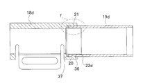
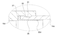
- FIGS. 15 to 17 show a sixth example of the embodiment of the present invention.
- the cylindrical portion 36 provided from the intermediate portion to the rear end portion of the metal ring 22d is internally fitted and fixed at the joint portion between the main body portion 18d and the cylindrical member 19d.
- an outward flange-like flange portion 37 is provided in a state of projecting radially outward at the front end portion of the ring 22d, and the rear side surface (the right side surface in FIGS. 15 to 17) of the flange portion 37 is connected to the cylindrical member 19d. Is in contact with the front end face (left end face in FIGS. 15 to 17).
- the ring 22d when manufacturing the steering column, when the ring 22d is press-fitted into the joint between the main body portion 18d and the cylindrical member 19d, the ring 22d is stopped at an appropriate position, and the ring 22d It is possible to easily prevent entry into the back side of the cylindrical member 19d. That is, when manufacturing the steering column of this example, the cylindrical portion 36 of the ring 22d is fitted in advance by an interference fit to the front end portion of the cylindrical member 19d protruding into the mold 23. When the cylindrical portion 36 is press-fitted toward the back side of the cylindrical member 19d, the rear side surface (the right side surface in FIG. 17) of the collar portion 37 of the ring 22d and the front end surface (the left end surface in FIG.
- the ring 22d does not enter the inner side of the cylindrical member 19d (the right side in FIG. 17) any more and stops at an appropriate position.
- the front end portion of the cylindrical member is formed on the inner circumferential surface in the axial direction intermediate portion of the cylindrical member. It is necessary to devise such as providing a stepped portion so that the inner diameter of the portion excluding the portion is smaller than the outer diameter of the ring. As a result, the manufacturing cost of the steering column may increase, or the thickness of the portion excluding the front end portion of the cylindrical member may increase.
- Other configurations and operations are the same as those of the first example of the embodiment.
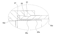
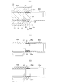
- FIGS. 18 to 20 show a seventh example of the embodiment of the invention.
- This example is a modification of the sixth example of the embodiment. That is, the outer diameter of the cylindrical portion 36a of the ring 22e is slightly smaller than the inner diameter of the front end portion of the cylindrical member 19d, as shown exaggeratedly in FIGS. A minute gap is provided between the inner peripheral surface of the front end portion of the cylindrical member 19d. For this reason, the same effect as the 3rd example of an embodiment can be acquired.
- Other configurations and operations are the same as in the sixth example of the embodiment.
- FIG. 21 shows an eighth example of the embodiment of the present invention.
- the front end surface of the cylindrical member 19e (FIG. 21) is disposed at one or a plurality of locations in the circumferential direction (four locations in the illustrated example).
- a concave groove 38 that is long in the axial direction. Then, the main body portion 18e and the cylindrical member 19e are coupled in the axial direction in a state in which the protrusion 39 provided on the inner peripheral surface of the rear end portion of the main body portion 18e is engaged with the concave groove 38. .
- the concave groove 38 is opened in the front end surface (left end surface in FIGS. 21 to 22) of the cylindrical member 19e, the molten metal of light alloy is fed to the back end portion of the mold 23 (see FIG. 5).
- the molten metal of light alloy is fed to the back end portion of the mold 23 (see FIG. 5).
- the engagement strength between the concave groove 38 and the protrusion 39 can be ensured.
- the sliding resistance can be increased and the coupling strength in the axial direction can be improved.
- the main body portion 18e and the cylindrical member are formed on the bottom surface of the concave groove 38 by forming irregularities extending in the axial direction and through holes that open to the bottom surface of the concave groove 38 and are closed by the ring 22d.
- the coupling strength in the axial direction with 19e can be improved more reliably.
- the configuration and operation of the other parts are the same as in the first example of the embodiment.
- FIG. 24 shows a ninth example of the embodiment of the invention.
- a large number of minute concave grooves are formed on the outer peripheral surface of the tip end portion of the cylindrical member 19f by knurling, and the uneven portion 40 is provided.
- a molten metal of light alloy is fed into the mold 23 (see FIG. 5) to form the main body portion, a part of the molten metal is fed into the concavo-convex portion 40, so that a minute amount is formed on the inner peripheral surface of the tip portion of the main body portion. Many ridges are formed.
- grooved part 40 provided by knurling may be either a flat knurl or a twill knurl.
- the concavo-convex portion 40 is a twill knurled line, the coupling strength can be ensured not only in the circumferential direction but also in the axial direction by the engagement of the minute groove and the minute protrusion.
- the configuration and operation of the other parts are the same as in the first example of the embodiment.
- FIG. 25 and 26 show a tenth example of the embodiment of the invention.
- This example is an example of the steering device of the present invention.
- This steering device is an impact absorption type steering device provided with a telescopic mechanism.
- the rear end portion of the inner column 41 is fitted into the front end portion of the outer column 10f so that the outer column 10f and the inner column 41 can be displaced in the axial direction.
- a housing 42 for housing a reduction gear or the like constituting the electric power steering device is coupled and fixed.
- Such a steering column 2b has a rear bracket 43 that supports the outer column 10f and front brackets 44 that are provided on both the left and right sides of the front end of the housing 42. It is supported.
- a steering column including any one of the column members of the first to ninth examples of the embodiment of the present invention is used for the outer column 10f constituting the steering column 2b.
- the steering device of this example further incorporates a steering lock device as shown in FIG.
- the steering shaft 3 is substantially prevented from rotating in the steering column 2b.
- substantially blocked means that the steering wheel 4 (see FIG. 29) is predetermined while the engaging recess 14 and the tip of the lock pin 16 (see FIG. 30) are engaged when the key is locked.
- the steering shaft 3 is allowed to rotate with respect to the key lock collar 15 and thus the steering column 2b. means.
- the steering shaft 3 does not rotate with a force sufficient to operate the steering wheel 4 in a normal driving posture in order to give a desired steering angle to the steered wheels.
- the column member of the present invention is not limited to the outer column of the steering column having the telescopic mechanism as described above, and can be applied to a steering column having no telescopic mechanism.
Abstract
Description
図1~図5は、本発明の実施の形態の第1例を示している。なお、本例を含めて、本発明のステアリングコラムの特徴は、ステアリングコラムを構成するコラム用部材である、アウタコラム10bの後半部(図1~図5の右側)の厚さを薄くしても、強度の確保を図ることができる構造を工業的に実現する点にある。その他の部分の構造および作用は、従来のステアリングコラムおよびその製造方法と同様であるから、同等部分に関する図示並びに説明は、省略もしくは簡略にし、以下、本例の特徴部分を中心に説明する。
図7は、本発明の実施の形態の第2例を示している。本例の場合には、アウタコラム10dを構成する円筒状部材19bの前端部外周面の周方向の1箇所または複数箇所(図示の例では4箇所)に、凹部32を設けている。そして、本体部分18bの後端部内周面のうち、凹部32と整合する位置に凸部33を設けて、凹部32と凸部33との係合により、本体部分18bと円筒状部材19bとの軸方向および周方向の結合強度を確保している。その他の部分の構成および作用は、実施の形態の第1例と同様である。
図8~図10は、本発明の実施の形態の第3例を示している。本例の場合、本体部分18と円筒状部材19との結合部で、円筒状部材19の内周面にリング22aを隙間嵌により内嵌している。リング22aの外径D22は、図8~図10に誇張して示すように、円筒状部材19の前端部の内径R19よりもわずかに小さくし(D22<R19)、リング22aの外周面と円筒状部材19の前端部の内周面との間に、円筒状の微小隙間を設けている。この微小隙間の径方向に関する厚さ寸法「(R19-D22)/2」は、円筒状部材19の前端部にリング22を挿入する際に、圧入する必要がなく、隙間嵌で挿入できる程度に、できる限り小さくして、金型23に軽合金の溶湯を送り込む作業の際に、微小隙間にこの溶湯が入り込むことがないか、入り込んでも少量に止まるようにしている。
図11および図12は、本発明の実施の形態の第4例を示している。本例の場合、本体部分18cの外径と円筒状部材19cの外径を同じ大きさとして、円筒状部材19cの前端部を本体部分18cの後端部に外嵌して、アウタコラム10eを構成するようにしている。このため、リング22bの後端部に、径方向外方に突出する鍔部34を設け、鍔部34の外周面を、円筒状部材19cの前端部の内径部分に内嵌固定している。そして、リング22cの中間部から前端部に設けられた小径部35と、円筒状部材19cの前端部とで本体部分18cの後端部を挟持して、本体部分18cと円筒状部材19cとを軸方向に結合している。この結果、本例の場合には、円筒状部材19cの内径を、本体部分18cの内径よりも大きくでき、円筒状部材19cの内径側に、キーロックカラー13(図28参照)を設けるための隙間を確保しやすくできる。本例では、円筒部材19の円周面に、形成した凹溝20aと、本体部分18の外周面に形成した突条21aとを係合させているため、本体部分18と円筒部材19の軸方向強度を確保することができる。その他の部分の構成および作用は、実施の形態の第1例と同様である。
図13および図14は、本発明の実施の形態の第5例を示している。本例は、実施の形態の第4例の変形例である。すなわち、リング22cの後端部に、径方向外方に突出する状態で設けた鍔部34aの外周面を、円筒状部材19cの前端部の内径部分に隙間嵌で内嵌固定している。そして、鍔部34aの外周面と円筒状部材19cの内周面との間に微小隙間を設けている。これにより、リング22cを円筒状部材19cの前端部に、圧入することなく挿入できる。その他の構成および作用は、実施の形態の第4例と同様である。
図15~図17は、本発明の実施の形態の第6例を示している。本例の場合、本体部分18dと円筒状部材19dとの結合部で、金属製のリング22dの中間部から後端部にかけて設けられた円筒部36を内嵌固定している。また、リング22dの前端部に径方向外方に突出した状態で、外向フランジ状の鍔部37を設け、鍔部37の後側面(図15~図17の右側面)を、円筒状部材19dの前端面(図15~図17の左端面)に当接させている。
図18~図20は、本発明の実施の形態の第7例を示している。本例は、実施の形態の第6例の変形例である。すなわち、リング22eの円筒部36aの外径を、図18~図20に誇張して示すように、円筒状部材19dの前端部の内径よりもわずかに小さくして、円筒部36aの外周面と円筒状部材19dの前端部の内周面との間に、微小隙間を設けている。このため、実施の形態の第3例と同様の効果を得ることができる。その他の構成および作用は、実施の形態の第6例と同様である。
図21~図23は、本発明の実施の形態の第8例を示している。本例の場合には、円筒状部材19eの前端部外周面のうちで、周方向の1箇所または複数箇所(図示の例では4箇所)に、それぞれが円筒状部材19eの前端面(図21および図22の左端面)に開口し、軸方向に長い、凹溝38を設けている。そして、凹溝38に、本体部分18eの後端部の内周面に設けた、突条39を係合させた状態で、本体部分18eと円筒状部材19eとを軸方向に結合している。
図24は、本発明の実施の形態の第9例を示している。本例の場合には、図24に多数本の直線で示すように、円筒状部材19fの先端部外周面にローレット加工により微小な凹溝を多数形成し、凹凸部40を設けている。そして、金型23(図5参照)に軽合金の溶湯を送り込んで、本体部分を形成する際に、凹凸部40に溶湯の一部を送り込むことにより、本体部分の先端部内周面に微小な突条を多数形成する。なお、ローレット加工により設ける凹凸部40は、平目ローレットと綾目ローレットとのどちらでもよい。凹凸部40を綾目ローレット目とした場合には、微小凹溝と微小突条との係合により、周方向に加えて軸方向についても、結合強度を確保できる。その他の部分の構成および作用は、実施の形態の第1例と同様である。
図25および図26は、本発明の実施の形態の第10例を示している。本例は、本発明のステアリング装置の1例である。このステアリング装置は、テレスコピック機構を備えた衝撃吸収式ステアリング装置となっている。このステアリング装置では、アウタコラム10fの前端部にインナコラム41の後端部を、アウタコラム10fとインナコラム41とが互いに軸方向に変位するのを可能な状態で内嵌している。インナコラム41の前端部には、電動式パワーステアリング装置を構成する減速機などを収納するためのハウジング42を結合固定している。このようなステアリングコラム2bは、アウタコラム10fを支持した後側ブラケット43と、ハウジング42の前端部左右両側に設けられた前側ブラケット44とを、車体に対し結合固定することにより、車体に対して支持されている。本例の場合、ステアリングコラム2bを構成するアウタコラム10fに、本発明の実施の形態の第1例~第9例のいずれかのコラム用部材を含むステアリングコラムが用いられている。
2、2a、2b ステアリングコラム
3、3a ステアリングシャフト
4 ステアリングホイール
5a、5b 自在継手
6 中間シャフト
7 ステアリングギヤユニット
8 入力軸
9 タイロッド
10、10a~10f アウタコラム
11 アウタチューブ
12 ステアリングロック装置
13 ロックユニット
14 係合凹部
15 キーロックカラー
16 ロックピン
17、17a ロック用透孔
18、18a~18e 本体部分
19、19a~19f 円筒状部材
20、21a 凹溝
21、21a 突条
22、22a~22e リング
23 金型
24 外側面
25 挿入孔
26 段差部
27 段差部
28 中子
29 先端部
30 基端部
31 段差面
32 凹部
33 凸部
34、34a 鍔部
35 小径部
36、36a 円筒部
37 鍔部
38 凹溝
39 突条
40 凹凸部
41 インナコラム
42 ハウジング
43 後側ブラケット
44 前側ブラケット
Claims (15)
- 全体が円筒状のステアリングコラムであって、このステアリングコラムを構成するコラム用部材が、
軽合金製の本体部分と、
前記本体部分の一方側端部にその他方側端部が嵌合することにより、軸方向に結合されている鉄系合金製の円筒状部材と、
前記本体部分と前記円筒状部材との結合部の内径側に内嵌固定される金属製のリングと、
を備える、ステアリングコラム。 - 前記リングの内径は、前記本体部分のうち前記結合部から軸方向に外れた部分の内径以上であり、前記円筒状部材の内径以下である、請求項1に記載のステアリングコラム。
- 前記リングが軽合金製である、請求項1に記載のステアリングコラム。
- 前記本体部分の一方側端部に前記円筒状部材の他方側端部が内嵌され、前記リングが、前記本体部分と前記円筒状部材との結合部の内周面に内嵌固定されている、請求項1に記載のステアリングコラム。
- 前記本体部分の一方側端部に前記円筒状部材の他方側端部が外嵌され、前記リングが、前記本体部分と前記円筒状部材との結合部の内周面に内嵌固定されている、請求項1に記載のステアリングコラム。
- 前記リングの外径が、前記本体部分と前記円筒状部材との結合部の内径よりも小さく、前記リングが、前記本体部分と前記円筒状部材との結合部の内径側に、前記リングの外周面と前記円筒状部材の前記他方側端部の内周面との間に隙間を設けた状態で内嵌固定されている、請求項1に記載のステアリングコラム。
- 前記リングは、前記本体部分の一方側端縁が前記リングの軸方向中間部の径方向外方に位置するように、軸方向に位置決めされている、請求項4に記載のステアリングコラム。
- 前記リングの他方側端部に、径方向外方に突出する外向フランジ状の鍔部が設けられており、この鍔部の一端側側面が、前記円筒状部材の他端側端面に当接している、請求項4に記載のステアリングコラム。
- 前記円筒状部材の軸方向中間部の1箇所位置に、ステアリングロック装置を構成するロック用透孔が設けられている、請求項1に記載のステアリングコラム。
- 請求項1に記載のステアリングコラムの製造方法であって、
前記円筒状部材の他方側端部に前記リングを内嵌し、
前記円筒状部材の他方側端部を、金型の一方側端面に開口する挿入孔に挿通し、この円筒状部材の他方側端部をこの金型内に突出させ、
前記リングに中子の一方側端部を挿通し、
前記金型に軽合金の溶湯を送り込み、前記本体部分を成形する、
工程により、前記コラム用部材を得る、ステアリングコラムの製造方法。 - 前記リングの内径が、前記本体部分の内径よりも小さく、前記円筒状部材の内径が、前記本体部分のうち前記結合部から軸方向に外れた部分の内径よりも大きくなるように、前記本体部分を成形するとともに、前記本体部分の成形後に、前記リングの内径側部分に切削加工を施して、このリングの内径を、前記本体部分のうち前記結合部から軸方向に外れた部分の内径以上で、前記円筒状部材の内径以下とする工程をさらに備える、請求項10に記載のステアリングコラムの製造方法。
- 前記リングの外径を、前記円筒状部材のうち、前記本体部分と前記円筒状部材との結合部となる前記他方側端部の内径よりも小さくし、前記リングを、このリングの外周面と前記円筒状部材の前記他方側端部の内周面との間に隙間を設けた状態で、前記円筒状部材の他方側端部に内嵌固定する、請求項10に記載のステアリングコラムの製造方法。
- 前記金型として、一方側端部寄り部分の内径側に段差部を有する金型を用い、前記円筒状部材の他方側端部を前記金型内に突出させた状態で、この金型の段差部を前記リングの軸方向中間部の径方向外方に位置させるとともに、前記溶湯の一部を前記段差部に向けて送り込むことにより、前記本体部分の端縁を形成する、請求項10に記載のステアリングコラムの製造方法。
- 前記リングとして、他方側端部に、径方向外方に突出する外向フランジ状の鍔部が設けられたリングを用い、この鍔部の一端側側面を、前記円筒状部材の他端側側面に当接させるとともに、このリングの他方側端部を前記金型内に突出させる、請求項10に記載のステアリングコラムの製造方法。
- 車体に支持されるステアリングコラムと、このステアリングコラムの内径側に回転可能に支持されたステアリングシャフトと、これらステアリングコラムとステアリングシャフトとの間に設けられ、作動時にこのステアリングシャフトがこのステアリングコラム内で回転することを実質的に阻止するステアリングロック装置とを備え、前記ステアリングコラムが請求項9に記載のステアリングコラムである、ステアリング装置。
Priority Applications (3)
| Application Number | Priority Date | Filing Date | Title |
|---|---|---|---|
| EP12812140.7A EP2740647B1 (en) | 2011-07-26 | 2012-07-23 | Steering column and manufacturing method thereof, and steering device using said steering column |
| JP2012540223A JP5609982B2 (ja) | 2011-07-26 | 2012-07-23 | ステアリングコラムの製造方法 |
| US13/810,912 US9403210B2 (en) | 2011-07-26 | 2012-07-23 | Steering column and manufacturing method thereof, and steering apparatus using this steering column |
Applications Claiming Priority (10)
| Application Number | Priority Date | Filing Date | Title |
|---|---|---|---|
| JP2011-162690 | 2011-07-26 | ||
| JP2011162687 | 2011-07-26 | ||
| JP2011-162688 | 2011-07-26 | ||
| JP2011162690 | 2011-07-26 | ||
| JP2011-162686 | 2011-07-26 | ||
| JP2011-162687 | 2011-07-26 | ||
| JP2011162688 | 2011-07-26 | ||
| JP2011162686 | 2011-07-26 | ||
| JP2011-180449 | 2011-08-22 | ||
| JP2011180449 | 2011-08-22 |
Publications (1)
| Publication Number | Publication Date |
|---|---|
| WO2013015257A1 true WO2013015257A1 (ja) | 2013-01-31 |
Family
ID=47569781
Family Applications (1)
| Application Number | Title | Priority Date | Filing Date |
|---|---|---|---|
| PCT/JP2012/068627 WO2013015257A1 (ja) | 2011-07-26 | 2012-07-23 | ステアリングコラムとその製造方法、およびこのステアリングコラムを用いたステアリング装置 |
Country Status (5)
| Country | Link |
|---|---|
| US (1) | US9403210B2 (ja) |
| EP (1) | EP2740647B1 (ja) |
| JP (2) | JP5609982B2 (ja) |
| CN (2) | CN202847785U (ja) |
| WO (1) | WO2013015257A1 (ja) |
Cited By (1)
| Publication number | Priority date | Publication date | Assignee | Title |
|---|---|---|---|---|
| KR20190055570A (ko) * | 2017-11-15 | 2019-05-23 | 남양넥스모 주식회사 | 조향 컬럼 |
Families Citing this family (11)
| Publication number | Priority date | Publication date | Assignee | Title |
|---|---|---|---|---|
| JP5609982B2 (ja) * | 2011-07-26 | 2014-10-22 | 日本精工株式会社 | ステアリングコラムの製造方法 |
| US8960044B2 (en) * | 2011-07-26 | 2015-02-24 | Nsk, Ltd. | Manufacturing method for a steering column, and steering apparatus that uses that steering column |
| US9321102B2 (en) * | 2011-10-11 | 2016-04-26 | Nsk Ltd. | Steering column and manufacturing method thereof |
| JP5900646B2 (ja) * | 2012-11-26 | 2016-04-06 | 日本精工株式会社 | ステアリング装置 |
| JP5804221B2 (ja) * | 2013-04-03 | 2015-11-04 | 日本精工株式会社 | テレスコピックステアリング装置用アウタコラム |
| KR102123259B1 (ko) * | 2014-11-06 | 2020-06-16 | 남양넥스모 주식회사 | 스티어링 컬럼 제작용 금형 장치 및 이를 이용한 금형 공법 |
| DE102016114678A1 (de) * | 2016-08-08 | 2018-02-08 | Thyssenkrupp Ag | Drehlageranordnung für eine Lenksäule eines Kraftfahrzeugs |
| EP3511225B1 (en) * | 2018-01-10 | 2020-11-25 | Volvo Car Corporation | A steering arrangement |
| FR3078940B1 (fr) * | 2018-03-16 | 2021-06-18 | Jtekt Europe Sas | Colonne de direction comportant un dispositif de blocage en rotation actionne par une motorisation |
| CN110181025B (zh) * | 2019-05-09 | 2021-01-15 | 安徽管益生新材料科技有限公司 | 一种金属管材模具焊接装置 |
| CN113560536B (zh) * | 2021-07-30 | 2023-05-30 | 共享装备股份有限公司 | 一种防铸件变形装置 |
Citations (5)
| Publication number | Priority date | Publication date | Assignee | Title |
|---|---|---|---|---|
| JPH068150U (ja) * | 1992-07-07 | 1994-02-01 | 日本精工株式会社 | 衝撃吸収式ステアリングシャフト |
| JP2007153088A (ja) * | 2005-12-02 | 2007-06-21 | Nsk Ltd | ステアリング装置 |
| JP2007223383A (ja) * | 2006-02-21 | 2007-09-06 | Nsk Ltd | ステアリング装置 |
| JP2008265646A (ja) * | 2007-04-24 | 2008-11-06 | Nsk Ltd | 車両用ステアリング装置 |
| JP2011073547A (ja) * | 2009-09-30 | 2011-04-14 | Nsk Ltd | ステアリング装置 |
Family Cites Families (22)
| Publication number | Priority date | Publication date | Assignee | Title |
|---|---|---|---|---|
| JPS4833566B1 (ja) * | 1969-09-10 | 1973-10-15 | ||
| JPS4833566A (ja) | 1971-08-31 | 1973-05-11 | ||
| JPH0190667U (ja) * | 1987-12-07 | 1989-06-14 | ||
| JPH068150A (ja) | 1992-06-26 | 1994-01-18 | Hitachi Koki Co Ltd | 圧縮空気ネジ締機 |
| DE4242896C2 (de) * | 1992-12-18 | 1994-10-13 | Daimler Benz Ag | Verfahren zum endseitigen Angießen eines Gußteiles an ein Hohlprofil |
| JP3100290B2 (ja) * | 1994-07-05 | 2000-10-16 | 株式会社山田製作所 | ステアリングコラムの支持構造 |
| JP3168841B2 (ja) * | 1994-09-22 | 2001-05-21 | 日本精工株式会社 | 衝撃吸収式ステアリングシャフトの製造方法 |
| GB2298448A (en) * | 1995-03-02 | 1996-09-04 | Torrington Co | Steering column locking assembly |
| CN1187162A (zh) * | 1995-03-02 | 1998-07-08 | 英国托林顿有限公司 | 转向盘轴锁紧组件及其制造方法 |
| US5722300A (en) * | 1996-08-16 | 1998-03-03 | General Motors Corporation | Motor vehicle steering column |
| JPH11311256A (ja) * | 1998-04-24 | 1999-11-09 | Nippon Seiko Kk | 衝撃吸収式ステアリングシャフト |
| JP4571341B2 (ja) * | 2001-06-18 | 2010-10-27 | 水島プレス工業株式会社 | ステアリング装置のダンパ機構 |
| JP2003072517A (ja) * | 2001-09-05 | 2003-03-12 | Koyo Seiko Co Ltd | ステアリングロック装置 |
| DE602004030908D1 (de) * | 2003-06-03 | 2011-02-17 | Nsk Ltd | Aufpralldämpfungslenksäulenvorrichtung für fahrzeug |
| US7699344B2 (en) | 2006-02-21 | 2010-04-20 | Nsk Ltd. | Steering device |
| DE102008005256B4 (de) * | 2008-01-18 | 2009-10-22 | Thyssenkrupp Presta Ag | Lenksäule mit Kunststoffgleithülse |
| US8960044B2 (en) * | 2011-07-26 | 2015-02-24 | Nsk, Ltd. | Manufacturing method for a steering column, and steering apparatus that uses that steering column |
| JP5609982B2 (ja) * | 2011-07-26 | 2014-10-22 | 日本精工株式会社 | ステアリングコラムの製造方法 |
| US9321102B2 (en) * | 2011-10-11 | 2016-04-26 | Nsk Ltd. | Steering column and manufacturing method thereof |
| EP2857281B1 (en) * | 2012-05-25 | 2018-01-17 | NSK Ltd. | Position adjustment device for electric steering wheel |
| US9180901B2 (en) * | 2012-07-04 | 2015-11-10 | Nsk Ltd. | Steering wheel position adjusting apparatus |
| CN104812634B (zh) * | 2012-11-26 | 2017-08-18 | 日本精工株式会社 | 转向装置 |
-
2012
- 2012-07-23 JP JP2012540223A patent/JP5609982B2/ja active Active
- 2012-07-23 WO PCT/JP2012/068627 patent/WO2013015257A1/ja active Application Filing
- 2012-07-23 EP EP12812140.7A patent/EP2740647B1/en not_active Not-in-force
- 2012-07-23 US US13/810,912 patent/US9403210B2/en active Active
- 2012-07-26 CN CN201220366219XU patent/CN202847785U/zh not_active Expired - Fee Related
- 2012-07-26 CN CN201210262151.5A patent/CN102897205B/zh not_active Expired - Fee Related
-
2014
- 2014-02-07 JP JP2014022149A patent/JP5794327B2/ja active Active
Patent Citations (5)
| Publication number | Priority date | Publication date | Assignee | Title |
|---|---|---|---|---|
| JPH068150U (ja) * | 1992-07-07 | 1994-02-01 | 日本精工株式会社 | 衝撃吸収式ステアリングシャフト |
| JP2007153088A (ja) * | 2005-12-02 | 2007-06-21 | Nsk Ltd | ステアリング装置 |
| JP2007223383A (ja) * | 2006-02-21 | 2007-09-06 | Nsk Ltd | ステアリング装置 |
| JP2008265646A (ja) * | 2007-04-24 | 2008-11-06 | Nsk Ltd | 車両用ステアリング装置 |
| JP2011073547A (ja) * | 2009-09-30 | 2011-04-14 | Nsk Ltd | ステアリング装置 |
Cited By (2)
| Publication number | Priority date | Publication date | Assignee | Title |
|---|---|---|---|---|
| KR20190055570A (ko) * | 2017-11-15 | 2019-05-23 | 남양넥스모 주식회사 | 조향 컬럼 |
| KR102146755B1 (ko) * | 2017-11-15 | 2020-08-21 | 남양넥스모 주식회사 | 조향 컬럼 |
Also Published As
| Publication number | Publication date |
|---|---|
| EP2740647B1 (en) | 2018-09-05 |
| CN202847785U (zh) | 2013-04-03 |
| CN102897205A (zh) | 2013-01-30 |
| US20140311273A1 (en) | 2014-10-23 |
| JP5794327B2 (ja) | 2015-10-14 |
| JP5609982B2 (ja) | 2014-10-22 |
| EP2740647A1 (en) | 2014-06-11 |
| JP2014139075A (ja) | 2014-07-31 |
| US9403210B2 (en) | 2016-08-02 |
| JPWO2013015257A1 (ja) | 2015-02-23 |
| EP2740647A4 (en) | 2015-04-29 |
| CN102897205B (zh) | 2015-04-01 |
Similar Documents
| Publication | Publication Date | Title |
|---|---|---|
| JP5794327B2 (ja) | ステアリングコラム | |
| JP5741726B2 (ja) | テレスコピック機構付ステアリングコラム用アウタコラム | |
| JP5835438B2 (ja) | ステアリングコラムの製造方法 | |
| JP5804221B2 (ja) | テレスコピックステアリング装置用アウタコラム | |
| JP5804211B2 (ja) | テレスコピックステアリング装置およびアウタコラム | |
| JP6048594B2 (ja) | テレスコピックステアリング装置用アウタコラム | |
| JP5962329B2 (ja) | ステアリングコラム | |
| JP5939104B2 (ja) | ステアリングコラムの製造方法 | |
| WO2014188905A1 (ja) | テレスコピックステアリング装置用アウタコラム及びテレスコピックステアリング装置 | |
| JP2014213655A (ja) | ステアリングコラム及びその製造方法 | |
| JP2014040207A5 (ja) | ||
| JP2015009641A (ja) | ステアリングコラム及びその製造方法 | |
| JP2016155394A (ja) | テレスコピックステアリング装置用アウタコラム及びテレスコピックステアリング装置 | |
| JP2014061748A5 (ja) | ||
| JP2016155393A (ja) | テレスコピックステアリング装置用アウタコラム及びテレスコピックステアリング装置 |
Legal Events
| Date | Code | Title | Description |
|---|---|---|---|
| ENP | Entry into the national phase |
Ref document number: 2012540223 Country of ref document: JP Kind code of ref document: A |
|
| WWE | Wipo information: entry into national phase |
Ref document number: 2012812140 Country of ref document: EP |
|
| 121 | Ep: the epo has been informed by wipo that ep was designated in this application |
Ref document number: 12812140 Country of ref document: EP Kind code of ref document: A1 |
|
| NENP | Non-entry into the national phase |
Ref country code: DE |
|
| WWE | Wipo information: entry into national phase |
Ref document number: 13810912 Country of ref document: US |