WO2013014741A1 - 車両制御装置 - Google Patents
車両制御装置 Download PDFInfo
- Publication number
- WO2013014741A1 WO2013014741A1 PCT/JP2011/066871 JP2011066871W WO2013014741A1 WO 2013014741 A1 WO2013014741 A1 WO 2013014741A1 JP 2011066871 W JP2011066871 W JP 2011066871W WO 2013014741 A1 WO2013014741 A1 WO 2013014741A1
- Authority
- WO
- WIPO (PCT)
- Prior art keywords
- vehicle
- deceleration
- engine
- control device
- traveling
- Prior art date
Links
Images


Classifications
-
- B—PERFORMING OPERATIONS; TRANSPORTING
- B60—VEHICLES IN GENERAL
- B60W—CONJOINT CONTROL OF VEHICLE SUB-UNITS OF DIFFERENT TYPE OR DIFFERENT FUNCTION; CONTROL SYSTEMS SPECIALLY ADAPTED FOR HYBRID VEHICLES; ROAD VEHICLE DRIVE CONTROL SYSTEMS FOR PURPOSES NOT RELATED TO THE CONTROL OF A PARTICULAR SUB-UNIT
- B60W10/00—Conjoint control of vehicle sub-units of different type or different function
- B60W10/02—Conjoint control of vehicle sub-units of different type or different function including control of driveline clutches
-
- B—PERFORMING OPERATIONS; TRANSPORTING
- B60—VEHICLES IN GENERAL
- B60W—CONJOINT CONTROL OF VEHICLE SUB-UNITS OF DIFFERENT TYPE OR DIFFERENT FUNCTION; CONTROL SYSTEMS SPECIALLY ADAPTED FOR HYBRID VEHICLES; ROAD VEHICLE DRIVE CONTROL SYSTEMS FOR PURPOSES NOT RELATED TO THE CONTROL OF A PARTICULAR SUB-UNIT
- B60W30/00—Purposes of road vehicle drive control systems not related to the control of a particular sub-unit, e.g. of systems using conjoint control of vehicle sub-units, or advanced driver assistance systems for ensuring comfort, stability and safety or drive control systems for propelling or retarding the vehicle
- B60W30/18—Propelling the vehicle
- B60W30/18009—Propelling the vehicle related to particular drive situations
- B60W30/18072—Coasting
-
- F—MECHANICAL ENGINEERING; LIGHTING; HEATING; WEAPONS; BLASTING
- F02—COMBUSTION ENGINES; HOT-GAS OR COMBUSTION-PRODUCT ENGINE PLANTS
- F02D—CONTROLLING COMBUSTION ENGINES
- F02D7/00—Other fuel-injection control
-
- F—MECHANICAL ENGINEERING; LIGHTING; HEATING; WEAPONS; BLASTING
- F16—ENGINEERING ELEMENTS AND UNITS; GENERAL MEASURES FOR PRODUCING AND MAINTAINING EFFECTIVE FUNCTIONING OF MACHINES OR INSTALLATIONS; THERMAL INSULATION IN GENERAL
- F16D—COUPLINGS FOR TRANSMITTING ROTATION; CLUTCHES; BRAKES
- F16D48/00—External control of clutches
- F16D48/06—Control by electric or electronic means, e.g. of fluid pressure
-
- B—PERFORMING OPERATIONS; TRANSPORTING
- B60—VEHICLES IN GENERAL
- B60W—CONJOINT CONTROL OF VEHICLE SUB-UNITS OF DIFFERENT TYPE OR DIFFERENT FUNCTION; CONTROL SYSTEMS SPECIALLY ADAPTED FOR HYBRID VEHICLES; ROAD VEHICLE DRIVE CONTROL SYSTEMS FOR PURPOSES NOT RELATED TO THE CONTROL OF A PARTICULAR SUB-UNIT
- B60W30/00—Purposes of road vehicle drive control systems not related to the control of a particular sub-unit, e.g. of systems using conjoint control of vehicle sub-units, or advanced driver assistance systems for ensuring comfort, stability and safety or drive control systems for propelling or retarding the vehicle
- B60W30/18—Propelling the vehicle
- B60W30/18009—Propelling the vehicle related to particular drive situations
- B60W30/18072—Coasting
- B60W2030/1809—Without torque flow between driveshaft and engine, e.g. with clutch disengaged or transmission in neutral
-
- B—PERFORMING OPERATIONS; TRANSPORTING
- B60—VEHICLES IN GENERAL
- B60W—CONJOINT CONTROL OF VEHICLE SUB-UNITS OF DIFFERENT TYPE OR DIFFERENT FUNCTION; CONTROL SYSTEMS SPECIALLY ADAPTED FOR HYBRID VEHICLES; ROAD VEHICLE DRIVE CONTROL SYSTEMS FOR PURPOSES NOT RELATED TO THE CONTROL OF A PARTICULAR SUB-UNIT
- B60W2720/00—Output or target parameters relating to overall vehicle dynamics
- B60W2720/10—Longitudinal speed
- B60W2720/106—Longitudinal acceleration
-
- F—MECHANICAL ENGINEERING; LIGHTING; HEATING; WEAPONS; BLASTING
- F16—ENGINEERING ELEMENTS AND UNITS; GENERAL MEASURES FOR PRODUCING AND MAINTAINING EFFECTIVE FUNCTIONING OF MACHINES OR INSTALLATIONS; THERMAL INSULATION IN GENERAL
- F16D—COUPLINGS FOR TRANSMITTING ROTATION; CLUTCHES; BRAKES
- F16D2500/00—External control of clutches by electric or electronic means
- F16D2500/30—Signal inputs
- F16D2500/31—Signal inputs from the vehicle
- F16D2500/3101—Detection of a brake actuation by a sensor on the brake
-
- F—MECHANICAL ENGINEERING; LIGHTING; HEATING; WEAPONS; BLASTING
- F16—ENGINEERING ELEMENTS AND UNITS; GENERAL MEASURES FOR PRODUCING AND MAINTAINING EFFECTIVE FUNCTIONING OF MACHINES OR INSTALLATIONS; THERMAL INSULATION IN GENERAL
- F16D—COUPLINGS FOR TRANSMITTING ROTATION; CLUTCHES; BRAKES
- F16D2500/00—External control of clutches by electric or electronic means
- F16D2500/30—Signal inputs
- F16D2500/31—Signal inputs from the vehicle
- F16D2500/3108—Vehicle speed
-
- F—MECHANICAL ENGINEERING; LIGHTING; HEATING; WEAPONS; BLASTING
- F16—ENGINEERING ELEMENTS AND UNITS; GENERAL MEASURES FOR PRODUCING AND MAINTAINING EFFECTIVE FUNCTIONING OF MACHINES OR INSTALLATIONS; THERMAL INSULATION IN GENERAL
- F16D—COUPLINGS FOR TRANSMITTING ROTATION; CLUTCHES; BRAKES
- F16D2500/00—External control of clutches by electric or electronic means
- F16D2500/30—Signal inputs
- F16D2500/312—External to the vehicle
- F16D2500/3125—Driving resistance, i.e. external factors having an influence in the traction force, e.g. road friction, air resistance, road slope
- F16D2500/3127—Road slope
-
- F—MECHANICAL ENGINEERING; LIGHTING; HEATING; WEAPONS; BLASTING
- F16—ENGINEERING ELEMENTS AND UNITS; GENERAL MEASURES FOR PRODUCING AND MAINTAINING EFFECTIVE FUNCTIONING OF MACHINES OR INSTALLATIONS; THERMAL INSULATION IN GENERAL
- F16D—COUPLINGS FOR TRANSMITTING ROTATION; CLUTCHES; BRAKES
- F16D2500/00—External control of clutches by electric or electronic means
- F16D2500/30—Signal inputs
- F16D2500/314—Signal inputs from the user
- F16D2500/31406—Signal inputs from the user input from pedals
- F16D2500/3144—Accelerator pedal position
-
- F—MECHANICAL ENGINEERING; LIGHTING; HEATING; WEAPONS; BLASTING
- F16—ENGINEERING ELEMENTS AND UNITS; GENERAL MEASURES FOR PRODUCING AND MAINTAINING EFFECTIVE FUNCTIONING OF MACHINES OR INSTALLATIONS; THERMAL INSULATION IN GENERAL
- F16D—COUPLINGS FOR TRANSMITTING ROTATION; CLUTCHES; BRAKES
- F16D2500/00—External control of clutches by electric or electronic means
- F16D2500/30—Signal inputs
- F16D2500/314—Signal inputs from the user
- F16D2500/3146—Signal inputs from the user input from levers
- F16D2500/31466—Gear lever
-
- F—MECHANICAL ENGINEERING; LIGHTING; HEATING; WEAPONS; BLASTING
- F16—ENGINEERING ELEMENTS AND UNITS; GENERAL MEASURES FOR PRODUCING AND MAINTAINING EFFECTIVE FUNCTIONING OF MACHINES OR INSTALLATIONS; THERMAL INSULATION IN GENERAL
- F16D—COUPLINGS FOR TRANSMITTING ROTATION; CLUTCHES; BRAKES
- F16D2500/00—External control of clutches by electric or electronic means
- F16D2500/50—Problem to be solved by the control system
- F16D2500/508—Relating driving conditions
- F16D2500/5085—Coasting
-
- F—MECHANICAL ENGINEERING; LIGHTING; HEATING; WEAPONS; BLASTING
- F16—ENGINEERING ELEMENTS AND UNITS; GENERAL MEASURES FOR PRODUCING AND MAINTAINING EFFECTIVE FUNCTIONING OF MACHINES OR INSTALLATIONS; THERMAL INSULATION IN GENERAL
- F16D—COUPLINGS FOR TRANSMITTING ROTATION; CLUTCHES; BRAKES
- F16D2500/00—External control of clutches by electric or electronic means
- F16D2500/70—Details about the implementation of the control system
- F16D2500/704—Output parameters from the control unit; Target parameters to be controlled
- F16D2500/70402—Actuator parameters
- F16D2500/7041—Position
-
- F—MECHANICAL ENGINEERING; LIGHTING; HEATING; WEAPONS; BLASTING
- F16—ENGINEERING ELEMENTS AND UNITS; GENERAL MEASURES FOR PRODUCING AND MAINTAINING EFFECTIVE FUNCTIONING OF MACHINES OR INSTALLATIONS; THERMAL INSULATION IN GENERAL
- F16D—COUPLINGS FOR TRANSMITTING ROTATION; CLUTCHES; BRAKES
- F16D2500/00—External control of clutches by electric or electronic means
- F16D2500/70—Details about the implementation of the control system
- F16D2500/704—Output parameters from the control unit; Target parameters to be controlled
- F16D2500/70422—Clutch parameters
- F16D2500/70424—Outputting a clutch engaged-disengaged signal
-
- Y—GENERAL TAGGING OF NEW TECHNOLOGICAL DEVELOPMENTS; GENERAL TAGGING OF CROSS-SECTIONAL TECHNOLOGIES SPANNING OVER SEVERAL SECTIONS OF THE IPC; TECHNICAL SUBJECTS COVERED BY FORMER USPC CROSS-REFERENCE ART COLLECTIONS [XRACs] AND DIGESTS
- Y02—TECHNOLOGIES OR APPLICATIONS FOR MITIGATION OR ADAPTATION AGAINST CLIMATE CHANGE
- Y02T—CLIMATE CHANGE MITIGATION TECHNOLOGIES RELATED TO TRANSPORTATION
- Y02T10/00—Road transport of goods or passengers
- Y02T10/60—Other road transportation technologies with climate change mitigation effect
Definitions
- the present invention relates to a vehicle control device.
- Patent Literature 1 discloses a technique for determining whether or not the inertial running can be performed based on the transition of these coordinate points on the coasting control determination map using the accelerator opening and the clutch rotational speed as indices.
- the driver's intention to decelerate when the inertial traveling is performed depends on the traveling environment or traveling scene of the vehicle. May cause a sense of discomfort or anxiety. For example, when driving on a steep uphill or downhill or when there is an obvious deceleration intention due to a signal or railroad crossing, the driver may feel uncomfortable or uneasy when coasting.
- the present invention has been made in view of the above, and an object of the present invention is to provide a vehicle control device that can suppress the execution of inertial running that can give a driver a sense of incongruity or anxiety.
- a vehicle control device cuts off power transmission between an engine and drive wheels and causes the vehicle to travel by inertia when there is no acceleration / deceleration request to the vehicle during traveling.
- a vehicle control device for the vehicle capable of coasting, wherein the vehicle is in a state of traveling and there is no acceleration / deceleration request for the vehicle, and power is transmitted between the engine and the driving wheels.
- whether or not the inertial running is performed by comparing a requested deceleration that estimates the deceleration required for the vehicle later with a coasting deceleration that estimates the deceleration when the inertial running is performed.
- the power transmission between the engine and the driving wheel is interrupted to perform the inertia traveling, and when it is determined not to perform the inertia traveling, En And maintains the power transmission between the emission and the drive wheels.
- the requested deceleration is the larger of an expected deceleration when there is no deceleration request for the vehicle and an expected deceleration when there is a deceleration request for the vehicle. It is preferable.
- the expected deceleration when there is no deceleration request for the vehicle is determined based on the vehicle speed and the road gradient.
- the vehicle control device includes an information acquisition device that acquires surrounding information of the vehicle, and an expected deceleration when there is a deceleration request for the vehicle is obtained from the surrounding information of the vehicle acquired by the information acquisition device. Preferably it is estimated.
- a determination criterion for determining whether or not to carry out the inertial traveling is changed according to a traveling scene of the vehicle.
- control device it is preferable to perform control to stop engine fuel injection when it is determined that the inertial running is not performed.
- the vehicle control device when the coasting condition is satisfied, the requested deceleration that estimates the deceleration required for the vehicle, and the coasting deceleration that estimates the deceleration when coasting is performed, Since it is determined whether or not coasting is performed, it is possible to avoid the coasting depending on the relationship between the required deceleration and the coasting deceleration.
- the vehicle control device when the driver desires deceleration greater than the current deceleration, the situation where inertial traveling is performed is less likely to occur, and the frequency of giving the driver a sense of discomfort and anxiety can be greatly reduced.
- the vehicle control device has an effect that it is possible to suppress the inertial running that may give the driver a sense of discomfort and anxiety.
- FIG. 1 is a diagram showing a schematic configuration of a vehicle control apparatus according to an embodiment of the present invention.
- FIG. 2 is a flowchart showing inertial running control processing by the vehicle control device according to the present embodiment.
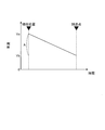
- FIG. 3 is a diagram for explaining a method of calculating the expected deceleration Dt_int when there is a deceleration request for the vehicle.
- FIG. 4 is a diagram illustrating an example of a map for calculating the expected deceleration Dt_unint when there is no deceleration request for the vehicle.
- FIG. 5 is a diagram for explaining each element for calculating the coasting deceleration Dn.
- the vehicle control apparatus 10 which concerns on one Embodiment of this invention is demonstrated.
- the vehicle control device 10 of this embodiment is mounted on a vehicle 1.
- This vehicle 1 includes an engine 2, a transmission 3, and drive wheels 4.
- the engine 2 is an internal combustion engine that is a driving source for driving the vehicle 1, and the driving force is controlled according to the fuel injection amount.
- the transmission 3 forms a power transmission mechanism that transmits the driving force generated by the engine 2 to the driving wheel 4 side.
- the transmission 3 is provided with a clutch C1 that is connected to the rotation shaft of the engine 2 so as to be freely connected and disconnected.
- the clutch C1 is, for example, a friction engagement type clutch device, which connects the engine 2 and the drive wheel 4 when engaged, transmits the driving force of the engine 2 to the drive wheel 4 side, and separates both when released. Transmission of driving force from the engine 2 to the driving wheel 4 side can be cut off.
- the drive wheels 4 are rotated by the driving force of the engine 2 transmitted via the transmission 3 and can travel forward or backward in the vehicle 1.
- Each part of the vehicle 1 such as the engine 2 and the transmission 3 (clutch C1) is controlled by the vehicle control device 10 based on information from various sensors in the vehicle.
- the vehicle control device 10 interrupts the power transmission between the engine 2 and the drive wheels 4 and causes the vehicle 1 to travel by inertia when there is no acceleration / deceleration request to the vehicle 1 during traveling. It is comprised so that control can be performed.
- the inertial running control specifically includes at least one of deceleration eco-run control, free-run control, and N coasting control.
- the deceleration eco-run control, the free-run control, and the N coasting control are travel controls in which the vehicle 1 travels by disengaging the power transmission between the engine 2 and the drive wheels 4 by opening the clutch C1, respectively. It is intended to perform inertial traveling that causes the vehicle to travel.
- Deceleration eco-run control and free-run control are controls in which the vehicle 1 travels while the clutch C1 is released and the engine 2 is stopped.
- fuel consumption can be improved by stopping the fuel consumption in the engine 2.
- the deceleration eco-run control and the free-run control execute idling stop by stopping the operation of the engine 2 when the vehicle 1 decelerates or stops when the deceleration eco-run control is mainly driven by the driver's braking operation (braking operation).
- the free-run control is not limited to when the vehicle 1 is decelerated and stopped when the brake operation is performed, but is different in that the engine 2 is actively stopped to perform idling stop.
- N coasting control is to release the clutch C1 and drive the vehicle 1 while the engine 2 is operating.
- the engine brake does not act, so the traveling load can be reduced and the fuel consumption can be improved. Further, since the engine 2 remains rotating, the acceleration response is excellent when returning from the N coasting control.
- ⁇ coasting control such as deceleration eco-run control, free-run control, and N coasting control is generally executed when no acceleration request is made, such as when the accelerator is off.
- the execution conditions of each control are determined with respect to, for example, the brake operation state, the vehicle speed, the battery charge amount, the gradient, and the like.
- vehicle control device 10 of the present embodiment is also configured to be able to execute fuel cut control for stopping fuel injection to the engine 2 during traveling, and to improve fuel consumption.
- the vehicle control device 10 is connected to an accelerator opening sensor 21, a shift position sensor 22, a vehicle speed sensor 23, a gradient sensor 24, a brake sensor 25, an infrastructure information acquisition device 26, an engine 2 and a transmission 3 (clutch C1).
- Accelerator opening sensor 21 detects the accelerator opening proportional to the amount of operation of the accelerator pedal.
- the shift position sensor 22 detects a shift position corresponding to the position of the shift lever.
- the vehicle speed sensor 23 detects the traveling speed of the vehicle 1.
- the vehicle speed sensor 23 can detect the vehicle speed based on the rotational speed of each wheel of the vehicle 1, for example.
- the gradient sensor 24 detects the road surface gradient.
- the gradient sensor 24 can detect or estimate the gradient of the road surface on which the vehicle 1 travels based on the front-rear direction inclination of the vehicle 1.
- the brake sensor 25 detects the amount of operation with respect to the brake pedal and the presence or absence of a brake operation.
- the operation amount with respect to the brake pedal is, for example, a pedal stroke of the brake pedal or a pedaling force input to the brake pedal.
- the presence or absence of a brake operation can be detected by, for example, a switch connected to a brake pedal.
- the infrastructure information acquisition device (information acquisition device) 26 acquires infrastructure information (ambient information) around the vehicle 1 that can be acquired in cooperation with the infrastructure.
- the infrastructure information acquisition device 26 is, for example, a device that transmits / receives various types of information to a road-to-vehicle communication device of the vehicle 1 from a transmission / reception device such as an optical beacon installed on the roadside, a GPS device, a navigation device, a vehicle-to-vehicle communication device, VICS (Vehicle Information and Communication System: Road traffic information communication system) Consists of various devices such as devices that receive information from the center.
- the infrastructure information acquisition device 26 acquires, for example, road information of a road on which the vehicle 1 travels, signal information regarding a traffic signal ahead of the vehicle 1 in the traveling direction, and the like as infrastructure information.
- the road information typically includes speed limit information on a road on which the vehicle 1 is traveling, stop line position information on an intersection, and the like.
- the signal information typically includes signal cycle information such as the lighting cycle of the traffic light, the yellow signal, and the red signal, and signal change timing.
- the vehicle control device 10 Based on such input information from the accelerator opening sensor 21, the shift position sensor 22, the vehicle speed sensor 23, the gradient sensor 24, the brake sensor 25, and the infrastructure information acquisition device 26, the vehicle control device 10 performs inertial running control. In accordance with this determination result, the control for releasing the clutch C1 of the transmission 3 or the fuel cut control for stopping the fuel injection of the engine 2 is executed.
- the vehicle control device 10 includes a required deceleration calculation unit 11, a coasting deceleration calculation unit 12, a determination bulk amount calculation unit 13, an inertia travel determination unit 14, and a fuel injection control unit. 15 and the clutch control unit 16 are realized.
- the requested deceleration calculation unit 11 is a requested deceleration that represents an estimated value of the deceleration required by the driver who drives the vehicle 1 while the vehicle 1 is traveling, in other words, an estimated value of the deceleration that is required for the vehicle 1 later.
- Dt is calculated. More specifically, the requested deceleration calculation unit 11 includes the “expected deceleration Dt_int when there is a deceleration request for the vehicle 1” and the “expected deceleration Dt_unint when there is no deceleration request for the vehicle 1 (in the case of cruise intention). Are calculated individually, and the larger of the two is calculated as the required deceleration Dt. The calculation of Dt_int and Dt_unint will be described later with reference to FIGS.
- the coasting deceleration calculation unit 12 calculates a coasting deceleration Dn that represents an estimated value of the deceleration of the vehicle 1 when the engine is disconnected, that is, when the engine is disconnected (clutch disengagement) in the current running state. calculate.
- the coasting deceleration Dn can be calculated from the vehicle speed, the road gradient, the air resistance of the vehicle 1, and the friction torque of each part of the vehicle 1. Details of the derivation process will be described later with reference to FIGS.
- the determination bulkiness calculation unit 13 calculates a determination bulkiness ⁇ D for determining whether or not inertial traveling control can be performed. This determination bulkiness amount ⁇ D can be changed according to the traveling scene.
- the coasting determination unit 14 satisfies the coasting condition, the requested deceleration Dt calculated by the requested deceleration calculation unit 11, the coasting deceleration Dn calculated by the coasting deceleration calculation unit 12, and the determination increase. Based on the determination bulkiness amount ⁇ D calculated by the amount calculation unit 13, it is determined whether or not to execute inertial running control. If it is determined that inertial running control is to be executed, a control command is transmitted to the clutch control unit 16 to cause the clutch C1 to be disengaged, and power transmission between the engine 2 and the drive wheels 4 is interrupted to inertia. Carry out driving. If it is determined that inertial running control is not to be executed, a control command is sent to the fuel injection control unit 15 while the power transmission between the engine 2 and the drive wheels 4 is maintained, and fuel injection to the engine 2 is stopped. Execute fuel cut control.
- the fuel injection control unit 15 controls the fuel injection amount of the engine 2 according to the control command from the inertia traveling determination unit 14.
- the clutch control unit 16 controls the release / engagement operation of the clutch C1 of the transmission 3 in accordance with a control command from the inertia traveling determination unit 14.
- the vehicle control device 10 is physically an electronic control unit (ECU) having a CPU (Central Processing Unit), a RAM (Random Access Memory), a ROM (Read Only Memory), and the like.
- the function of each part of the vehicle control device 10 shown in FIG. 1 is to operate various devices in the vehicle 1 under the control of the CPU by loading an application program held in the ROM into the RAM and executing it by the CPU. At the same time, it is realized by reading and writing data in RAM and ROM.
- the vehicle control device 10 is not limited to the functions of the above-described units, and includes various other functions used as the ECU of the vehicle 1.
- the above-mentioned ECU includes a plurality of engines such as an engine ECU that controls the engine 2, a T / M-ECU that controls the transmission 3, and an S & S-ECU that performs inertial running (S & S (start and stop) control).
- a configuration including an ECU may also be used.
- FIG. 2 is a flowchart showing inertial running control processing by the vehicle control device 10 according to the present embodiment
- FIG. 3 is a diagram for explaining a method of calculating the expected deceleration Dt_int when there is a deceleration request for the vehicle 1.
- 4 is a diagram showing an example of a map for calculating the expected deceleration Dt_unint when there is no deceleration request for the vehicle 1
- FIG. 5 shows each element for calculating the coasting deceleration Dn. It is a figure for demonstrating.
- the vehicle control device 10 executes inertial traveling control processing of the vehicle 1 according to the flowchart shown in FIG. This process is executed at predetermined intervals, for example.
- the inertia traveling determination unit 14 confirms whether or not the current shift position of the vehicle 1 is in the D (drive) range based on the input information from the shift position sensor 22 (S101). If the shift position is in the D range, the process proceeds to step S102. If the shift position is not in the D range, the process waits until the shift position is changed to the D range.
- the expected deceleration calculation unit 11 calculates the expected deceleration Dt_int when there is a deceleration request for the vehicle 1 (S103).
- the expected deceleration when there is a deceleration request for the vehicle 1 means that in the situation where there is an object that is a factor that the driver intends to decelerate the vehicle 1 ahead of the traveling direction of the vehicle 1. This means the deceleration estimated to be required for the vehicle 1 by the driver according to the object.
- the expected deceleration Dt_int at this time varies depending on the type of the object, the distance to the arrival point that reaches the object, and the like.
- the requested deceleration calculation unit 11 reduces the expectation when there is a deceleration request for the vehicle 1 based on the vehicle speed detected by the vehicle speed sensor 23 and the infrastructure information acquired by the infrastructure information acquisition device 26.
- the speed Dt_int is calculated by the following equation (1).
- Dt_int (Va ⁇ Va ⁇ Vb ⁇ Vb) / 2 / L (1)
- Va is the current vehicle speed
- Vb is the target vehicle speed at the arrival point
- L is the distance from the current position to the arrival point.
- Va is detected by the vehicle speed sensor 23.
- Vb and L can be variously set according to the type of the object.
- the infrastructure information acquired by the infrastructure information acquisition device 26 can be used to recognize and set the object ahead according to the driving scene. For example, red light, temporary stop, railroad crossing, front corner For example, a car that decelerates ahead.
- the target vehicle speed Vb at the reaching point decreases from the current vehicle speed Va. Therefore, the value of the expected deceleration Dt_int calculated by the equation (1) is Va and Vb. Increases (the line segment A in FIG. 3) increases, and the distance L from the current position to the arrival point decreases.
- the expected deceleration calculation unit 11 calculates the expected deceleration Dt_unit when there is no deceleration request for the vehicle 1 (S104).
- the “expected deceleration when there is no deceleration request for the vehicle 1” is a reduction estimated to be requested to the vehicle 1 by the driver according to the traveling state and road surface condition when the vehicle 1 is cruising. It means speed.
- V is the vehicle speed of the current vehicle 1
- ⁇ is the slope of the road on which the current vehicle 1 is traveling. When the slope ⁇ is positive, the road is uphill, and when it is negative, the road is downhill. Va is detected by the vehicle speed sensor 23, and ⁇ is detected by the gradient sensor 24.
- the expression (2) determines the expected deceleration Dt_unint based on the vehicle speed V and the gradient ⁇ using a map showing the relationship between the vehicle speed V, the gradient ⁇ and the expected deceleration Dt_unint as illustrated in FIG. To do.
- the horizontal axis in FIG. 4 indicates the road gradient ⁇
- the vertical axis indicates the expected deceleration Dt_unint.
- the degree of deceleration increases as it proceeds in the positive direction of the vertical axis, and the degree of acceleration increases as it proceeds in the negative direction of the vertical axis.
- a plurality of graphs plotting changes in expected deceleration Dt_unint according to road gradient ⁇ are shown according to vehicle speed V.
- the slope ⁇ is a positive value, that is, when the slope is uphill
- the expected deceleration Dt_unint is substantially constant regardless of the slope
- the slope ⁇ is a negative value
- the expected deceleration Dt_unit is set to increase as the slope of the downhill increases.
- the plurality of graphs corresponding to the vehicle speed V shift upward as the vehicle speed V increases, that is, in a direction in which the expected deceleration Dt_unint increases. That is, in the map shown in FIG. 4, the expected deceleration Dt_unit is set to increase as the descending slope increases and the vehicle speed increases.
- the requested deceleration calculation unit 11 calculates the requested deceleration Dt (S105).
- the requested deceleration calculation unit 11 calculates the requested deceleration Dt by the following equation (3).
- Dt Max (Dt_int, Dt_unint) (3)
- Dt_int is the expected deceleration when there is a deceleration request for the vehicle 1 calculated in step S103
- Dt_unint is the expected deceleration when there is no deceleration request for the vehicle 1 calculated in step S104.
- equation (3) the larger value of these calculated Dt_int and Dt_unint is calculated as the required deceleration Dt. Information on the calculated required deceleration Dt is transmitted to the inertial running determination unit 14.
- the coasting deceleration calculation unit 12 calculates the coasting deceleration Dn representing the deceleration of the vehicle 1 when the engine is disengaged (clutch release) in the current traveling state (S106).
- the air resistance F AIR can be expressed in more detail by equation (5).
- F AIR 1/2 ⁇ C D ⁇ V 2 A (5)
- C D is the air resistance coefficient
- ⁇ is the air density
- V is the vehicle speed
- A is the front projected area of the vehicle 1.
- the coasting deceleration Dn can be calculated by the following equation (6).
- Dn g ⁇ sin ⁇ + (F FRIC + F AIR ) / M (6)
- Information on the calculated coasting deceleration Dn is transmitted to the inertial running determination unit 14.
- the determination bulk amount calculation unit 13 calculates a determination bulk amount ⁇ D for determining whether or not the inertial traveling control can be performed (S107).
- the determination bulkiness calculation unit 13 can calculate by changing the determination bulkiness ⁇ D according to the traveling scene.
- Determination bulkiness amount ⁇ D is a parameter for adjusting a determination criterion regarding whether or not inertial traveling can be performed in inertial traveling determination (see step S108) to be described later, and coasting traveling is performed as the determination bulkiness amount ⁇ D is increased.
- the term “running scene” used in the present embodiment means a surrounding situation related to the acceleration / deceleration frequency of the vehicle 1. More specifically, when the traffic is congested, the distance from the preceding vehicle is small, and the driving is performed in an urban area. This includes when the vehicle speed and accelerator opening change is small within a certain past time, when driving in the suburbs, when driving on highways / automobile roads, and when driving on flat roads.
- the determination bulkiness calculation unit 13 cannot expect a large fuel efficiency improvement effect due to inertial travel.
- the amount ⁇ D is set small so that inertial running is less likely to occur.
- the determination bulkiness ⁇ D is set to be large so that inertial running is likely to occur. Information on the calculated determination bulkiness amount ⁇ D is transmitted to the inertial running determination unit 14.
- the inertia traveling determination unit 14 determines whether or not the inertia traveling can be performed (S108). Specifically, the inertia running determination unit 14 performs the determination using the condition of the following expression (7). Dt ⁇ Dn + ⁇ D (7)
- Dt is the required deceleration Dt calculated in step S105
- Dn is the coasting deceleration Dn calculated in step S106
- ⁇ D is the determination bulk amount ⁇ D calculated in step S107.
- the inertia traveling determination unit 14 satisfies the above-described expression (7), that is, “the requested deceleration Dt representing the estimated value of the deceleration that the driver obtains while the vehicle 1 is traveling” is “the engine in the current traveling state”.
- the deceleration required by the driver is It is determined that the inertial traveling can be performed by determining that it is less than the deceleration (coasting deceleration Dn) generated during inertial traveling, and that it is difficult for the driver to feel uncomfortable or uneasy due to inertial traveling.
- step S108 When it is determined in step S108 that inertial running is possible, the clutch control unit 16 releases the clutch C1 in the transmission 3 to perform the disconnection between the engine 2 and the drive wheel 4, and the engine 2 and the drive wheel 4 are disconnected.
- the power transmission between the two is cut off, and the vehicle 1 enters the coasting state (S109).
- step S108 the deceleration required by the driver (required deceleration Dt) exceeds the deceleration (coasting deceleration Dn) generated during coasting, and coasting is performed. If it is implemented, it is determined that the driver feels uncomfortable or uneasy, and it is determined that inertial running is not possible. In this case, engine disconnection (clutch disengagement) is not performed, and power transmission between the engine 2 and the drive wheels 4 is maintained. Instead, the fuel injection control unit 15 cuts fuel injection of the engine 2. Control is performed (S110).
- the required deceleration Dt calculation processing in steps S103 to S105, the coasting deceleration Dn calculation processing in step S106, and the determination bulkiness amount ⁇ D calculation processing in step S107 may be appropriately switched. Good.
- the vehicle control apparatus 10 performs inertial traveling in which the power transmission between the engine 2 and the drive wheels 4 is interrupted and the vehicle 1 travels by inertia when there is no acceleration / deceleration request to the vehicle 1 during traveling.
- the vehicle control device 10 for the vehicle 1 is capable of traveling, there is no acceleration / deceleration request for the vehicle 1, and power is transmitted between the engine 2 and the drive wheels 4.
- It is determined whether or not coasting is performed by comparing the requested deceleration Dt that estimates the deceleration required for the vehicle 1 and the coasting deceleration Dn that estimates the deceleration when coasting is performed. To do.
- power transmission between the engine 2 and the drive wheels 4 is interrupted to perform coasting, and when it is determined that coasting is not to be performed, the engine 2 and the driving wheels 4 Maintain power transmission between.
- This configuration makes it possible to avoid coasting depending on the relationship between the required deceleration Dt and the coasting deceleration Dn.
- a situation in which inertial traveling is performed is less likely to occur, and the frequency of giving the driver a sense of discomfort or anxiety can be greatly reduced.
- the “required deceleration Dt” is an expected deceleration Dt_unint when there is no deceleration request for the vehicle 1 and an expected deceleration Dt_int when there is a deceleration request for the vehicle 1. , Whichever is larger.
- the expected deceleration Dt_unit when there is no deceleration request for the vehicle 1 is determined based on the vehicle speed V and the road gradient ⁇ .
- the feeling of anxiety given to the driver during coasting varies depending on the current vehicle speed V of the vehicle 1 and the road gradient ⁇ when the vehicle 1 is traveling. For example, it is considered that anxiety increases when traveling at high speed or traveling down a steep downhill. Therefore, by adopting a configuration in which the expected deceleration Dt_unint is determined based on the vehicle speed V and the road gradient ⁇ , it is possible to carry out inertial traveling while reducing discomfort and anxiety in a wider range of traveling scenes.
- the vehicle control apparatus 10 of this embodiment is provided with the infrastructure information acquisition apparatus 26 which acquires the surrounding information of the vehicle 1, and the expected deceleration Dt_int when there exists a deceleration request
- the feeling of anxiety given to the driver during inertial driving varies depending on the distance L to the arrival point (signal, rail crossing, etc.) that is the object of deceleration of the vehicle 1 and the speed difference between the current speed Va and the target speed Vb.
- the configuration is such that the expected deceleration Dt_int is estimated based on the surrounding information of the vehicle 1 acquired by the infrastructure information acquisition device 26, thereby reducing discomfort and anxiety in a wider range of driving scenes. It is possible to carry out inertial running.
- the vehicle control device 10 of the present embodiment changes a determination criterion for determining whether or not to perform inertial traveling according to the traveling scene of the vehicle 1.
- the criterion for determining whether or not the inertial running can be performed is changed according to the driving scene, for example, in a driving scene in which inertial driving is less likely to cause a sense of incongruity, for example, the frequency of steady driving is high, the criterion is relaxed. Driving can easily occur and fuel consumption can be further improved.
- the vehicle control device 10 of the present embodiment maintains the power transmission between the engine 2 and the drive wheels 4 and further stops the fuel injection to the engine 2. Therefore, even when coasting is not performed, the fuel consumption can be reduced and further fuel consumption can be reduced.
- Each functional block of the vehicle control device 10 shown in FIG. 1 is merely illustrated for convenience of explanation, and may have other configurations as long as the same function can be realized.
- step S110 of the flowchart of FIG. 2 it was set as the structure which implements the fuel cut control which stops the fuel injection to the engine 2 when it determines with not performing inertial running, A configuration may be adopted in which fuel cut control is not performed when it is determined that inertial running is not performed.
- the inertia running determination part 14 determined whether the inertia running was feasible using the above equation (7). It is also possible to use an equation.
- the conditional expression (Dt ⁇ Dn) for comparing the requested deceleration Dt and the coasting deceleration Dn without adding the determination bulkiness amount ⁇ D to the determination condition, or the requested deceleration Dt and the coasting A conditional expression (Dt ⁇ ⁇ Dn) for comparing the deceleration Dn multiplied by a predetermined value ⁇ , and a conditional expression (Dt / ⁇ ) for comparing the ratio between the required deceleration Dt and the coasting deceleration Dn with a predetermined value ⁇ .
- Dn ⁇ may be used. Moreover, you may use the conditional expression (Dt ⁇ (alpha) * Dn + (DELTA) D, Dt / Dn ⁇ (beta) + (DELTA) D) which added determination bulkiness amount (DELTA) D to these formulas similarly to (7) Formula.
Abstract
Description
Dt_int=(Va×Va-Vb×Vb)/2/L ・・・(1)
ここで、Vaは現在の車速、Vbは到達点における目標車速、Lは現在位置から到達点までの距離である。Vaは車速センサ23により検出される。
・赤信号:Vb=0,L=信号までの距離
・一旦停止:Vb=0,L=一旦停止までの距離
・踏み切り:Vb=0,L=踏み切りまでの距離
・前方のコーナー:Vb=前方コーナーのRより安全に曲がれるためのコーナー入口車速,L=コーナー入口までの距離
・前方の減速している車:Vb=前方を走る車の速度,L=前車との車間距離
Dt_unint=MAP(V,θ) ・・・(2)
ここで、Vは現在の車両1の車速、θは現在の車両1が走行している道路の勾配である。勾配θは正値のとき道路は上り坂であり、負値のとき下り坂である。Vaは車速センサ23により検出され、θは勾配センサ24により検出される。
Dt=Max(Dt_int,Dt_unint) ・・・(3)
ここで、Dt_intは、ステップS103で算出した車両1に対する減速要求がある場合の期待減速度であり、Dt_unintは、ステップS104で算出した車両1に対する減速要求がない場合の期待減速度である。
M・Dn=M・g・sinθ+FFRIC+FAIR ・・・(4)
ここで、Mは車両1の重量、gは重力加速度、θは道路勾配(θ>0では上り坂)、FFRICはクラッチC1以降のドライブライン(自動変速機、プロペラ、デフ、ドライブシャフト、タイヤ)のフリクション抵抗の総計、FAIRは空気抵抗を表す。
FAIR=1/2・CDρV2A ・・・(5)
ここで、CDは空気抵抗係数、ρは空気密度、Vは車速、Aは車両1前面投影面積を表す。
Dn=g・sinθ+(FFRIC+FAIR)/M ・・・(6)
算出された惰行減速度Dnの情報は惰性走行判定部14に送信される。
Dt<Dn+ΔD ・・・(7)
ここで、DtはステップS105で算出された要求減速度Dtであり、DnはステップS106で算出された惰行減速度Dnであり、ΔDはステップS107で算出された判定嵩上量ΔDである。
2 エンジン
4 駆動輪
10 車両制御装置
26 インフラ情報取得装置(情報取得装置)
Dn 惰行減速度
Dt 要求減速度
Dt_int 車両に対する減速要求がある場合の期待減速度
Dt_unint 車両に対する減速要求がない場合の期待減速度
ΔD 判定嵩上量
Claims (6)
- 走行時に車両に対する加減速要求が無い場合に、エンジンと駆動輪との間の動力伝達を遮断し、惰性により前記車両を走行させる惰性走行を実施可能な前記車両のための車両制御装置であって、
走行時であって前記車両に対する加減速要求が無く、前記エンジンと前記駆動輪との間で動力が伝達される状態である場合、後に前記車両に要求される減速度を推定した要求減速度と、前記惰性走行を実施した場合の減速度を推定した惰行減速度とを比較することで、前記惰性走行を実施するか否かを判定し、前記惰性走行を実施すると判定したときに前記エンジンと前記駆動輪との間の動力伝達を遮断して前記惰性走行を実施し、前記惰性走行を実施しないと判定したときに前記エンジンと前記駆動輪との間の動力伝達を維持することを特徴とする車両制御装置。 - 前記要求減速度とは、
前記車両に対する減速要求がない場合の期待減速度と、
前記車両に対する減速要求がある場合の期待減速度と、
のうち大きい方である
ことを特徴とする、請求項1に記載の車両制御装置。 - 前記車両に対する減速要求がない場合の期待減速度は、
車速及び道路勾配に基づき決定されることを特徴とする、
請求項2に記載の車両制御装置。 - 前記車両の周囲情報を取得する情報取得装置を備え、
前記車両に対する減速要求がある場合の期待減速度は、
前記情報取得装置により取得した前記車両の周囲情報から推定される
ことを特徴とする、請求項2または3に記載の車両制御装置。 - 前記惰性走行を実施するか否かを判定するための判定基準を前記車両の走行シーンに応じて変化させることを特徴とする、請求項1~4のいずれか1項に記載の車両制御装置。
- 前記惰性走行を実施しないと判定したときに、さらに前記エンジンへの燃料噴射を停止する制御を実施することを特徴とする、請求項1~5のいずれか1項に記載の車両制御装置。
Priority Applications (7)
| Application Number | Priority Date | Filing Date | Title |
|---|---|---|---|
| US14/234,816 US9533669B2 (en) | 2011-07-25 | 2011-07-25 | Vehicle control device |
| PCT/JP2011/066871 WO2013014741A1 (ja) | 2011-07-25 | 2011-07-25 | 車両制御装置 |
| BR112014001906-1A BR112014001906B1 (pt) | 2011-07-25 | 2011-07-25 | Dispositivo de controle de veículo |
| EP11869887.7A EP2738412B1 (en) | 2011-07-25 | 2011-07-25 | Vehicle control device |
| RU2014102259/11A RU2561658C1 (ru) | 2011-07-25 | 2011-07-25 | Устройство управления автомобилем |
| CN201180072543.9A CN103732937B (zh) | 2011-07-25 | 2011-07-25 | 车辆控制装置 |
| JP2013525464A JP5733398B2 (ja) | 2011-07-25 | 2011-07-25 | 車両制御装置 |
Applications Claiming Priority (1)
| Application Number | Priority Date | Filing Date | Title |
|---|---|---|---|
| PCT/JP2011/066871 WO2013014741A1 (ja) | 2011-07-25 | 2011-07-25 | 車両制御装置 |
Publications (1)
| Publication Number | Publication Date |
|---|---|
| WO2013014741A1 true WO2013014741A1 (ja) | 2013-01-31 |
Family
ID=47600631
Family Applications (1)
| Application Number | Title | Priority Date | Filing Date |
|---|---|---|---|
| PCT/JP2011/066871 WO2013014741A1 (ja) | 2011-07-25 | 2011-07-25 | 車両制御装置 |
Country Status (7)
| Country | Link |
|---|---|
| US (1) | US9533669B2 (ja) |
| EP (1) | EP2738412B1 (ja) |
| JP (1) | JP5733398B2 (ja) |
| CN (1) | CN103732937B (ja) |
| BR (1) | BR112014001906B1 (ja) |
| RU (1) | RU2561658C1 (ja) |
| WO (1) | WO2013014741A1 (ja) |
Cited By (8)
| Publication number | Priority date | Publication date | Assignee | Title |
|---|---|---|---|---|
| WO2015120872A1 (de) * | 2014-02-15 | 2015-08-20 | Audi Ag | Verfahren zum betrieb eines den fahrer bei einem ausrollvorgang unterstützenden fahrerassistenzsystems und kraftfahrzeug |
| JP2016118238A (ja) * | 2014-12-19 | 2016-06-30 | 三菱ふそうトラック・バス株式会社 | 車両の走行制御装置 |
| JP2016118237A (ja) * | 2014-12-19 | 2016-06-30 | 三菱ふそうトラック・バス株式会社 | 車両の走行制御装置 |
| WO2016136874A1 (ja) * | 2015-02-25 | 2016-09-01 | 株式会社デンソー | 車両の惰性走行を制御する車両制御装置 |
| JP2016164049A (ja) * | 2015-03-06 | 2016-09-08 | 富士重工業株式会社 | ハイブリッド車両の制御装置 |
| JP2017020460A (ja) * | 2015-07-14 | 2017-01-26 | 日産自動車株式会社 | 惰性走行制御方法及び惰性走行制御装置 |
| JP2018062310A (ja) * | 2016-10-14 | 2018-04-19 | 日野自動車株式会社 | 車両制御装置 |
| JP2019137138A (ja) * | 2018-02-07 | 2019-08-22 | トヨタ自動車株式会社 | 変速制御装置 |
Families Citing this family (19)
| Publication number | Priority date | Publication date | Assignee | Title |
|---|---|---|---|---|
| BR112015020677A2 (pt) * | 2013-04-23 | 2017-07-18 | Honda Motor Co Ltd | transmissão sem escalonamento |
| JP6370388B2 (ja) * | 2014-09-19 | 2018-08-08 | 日立オートモティブシステムズ株式会社 | 車両制御装置及び車両制御方法 |
| JP6428324B2 (ja) * | 2015-02-03 | 2018-11-28 | トヨタ自動車株式会社 | 車両制御装置 |
| JP6565699B2 (ja) * | 2015-02-25 | 2019-08-28 | 株式会社デンソー | 車両制御装置 |
| US9827955B2 (en) * | 2015-03-06 | 2017-11-28 | Ford Global Technologies, Llc | Systems and methods to improve fuel economy using adaptive cruise in a hybrid electric vehicle when approaching traffic lights |
| FR3033540B1 (fr) * | 2015-03-10 | 2017-03-24 | Peugeot Citroen Automobiles Sa | Procede et dispositif de controle de l’ouverture / fermeture de la chaine de transmission d’un vehicule suivant un autre vehicule |
| JP6437891B2 (ja) * | 2015-07-03 | 2018-12-12 | 日立オートモティブシステムズ株式会社 | 自動車の制御装置 |
| DE102015213763B3 (de) * | 2015-07-22 | 2016-10-06 | Robert Bosch Gmbh | Verfahren zum Ermitteln einer Drehmomentgenauigkeit eines von einem riemen-getriebenen Startergenerator einer Brennkraftmaschine auf die Brennkraftmaschine übertragenen Drehmoments, Recheneinheit und maschinenlesbares Speichermedium |
| DE102015222262B4 (de) * | 2015-11-11 | 2020-04-23 | Audi Ag | Fahrerassistenzvorrichtung für ein Kraftfahrzeug sowie Verfahren zum Betreiben eines Kraftfahrzeugs |
| DE102015225011A1 (de) | 2015-12-11 | 2017-06-14 | Bayerische Motoren Werke Aktiengesellschaft | Geschwindigkeitsregelsystem zur Regelung der Geschwindigkeit eines Fahrzeugs |
| JP6689136B2 (ja) * | 2016-05-27 | 2020-04-28 | 日立オートモティブシステムズ株式会社 | 車両制御装置 |
| DE102016008363B4 (de) | 2016-07-08 | 2021-07-22 | Audi Ag | Verfahren zum Betrieb eines den Fahrer bei einem Ausrollvorgang unterstützenden Fahrerassistenzsystems in einem Kraftfahrzeug und Kraftfahrzeug |
| US10189453B2 (en) | 2016-10-05 | 2019-01-29 | Toyota Motor Engineering & Manufacturing North America, Inc. | Coasting guidance timing and drive force adjustment |
| US9896106B1 (en) | 2016-10-24 | 2018-02-20 | Toyota Motor Engineering & Manufacturing North America, Inc. | Coasting distance determination for coasting assistance system |
| US9898928B1 (en) | 2016-10-25 | 2018-02-20 | Toyota Motor Engineering & Manufacturing North America, Inc. | Coasting guidance timing and learning based on approach lane |
| JP2018122819A (ja) * | 2017-02-03 | 2018-08-09 | いすゞ自動車株式会社 | 走行制御装置および走行制御方法 |
| KR102286735B1 (ko) * | 2017-04-07 | 2021-08-05 | 현대자동차 주식회사 | 차량 주행 제어 장치 및 방법 |
| JP7180126B2 (ja) * | 2018-06-01 | 2022-11-30 | 株式会社デンソー | 走行制御装置 |
| CN116923357B (zh) * | 2022-02-14 | 2024-02-13 | 北京路凯智行科技有限公司 | 无人驾驶制动故障诊断系统 |
Citations (3)
| Publication number | Priority date | Publication date | Assignee | Title |
|---|---|---|---|---|
| JP2010203544A (ja) | 2009-03-04 | 2010-09-16 | Isuzu Motors Ltd | 惰行制御装置 |
| JP2010247773A (ja) * | 2009-04-20 | 2010-11-04 | Isuzu Motors Ltd | 惰行制御装置 |
| JP2011021702A (ja) * | 2009-07-16 | 2011-02-03 | Isuzu Motors Ltd | 惰行制御補助装置 |
Family Cites Families (33)
| Publication number | Priority date | Publication date | Assignee | Title |
|---|---|---|---|---|
| US4393964A (en) * | 1979-03-23 | 1983-07-19 | Ipanema Company | Hybrid power system and method for operating same |
| JP3430272B2 (ja) * | 1994-07-08 | 2003-07-28 | 日産自動車株式会社 | 自動変速機のロックアップ制御装置 |
| US5713425A (en) * | 1996-01-16 | 1998-02-03 | Ford Global Technologies, Inc. | Parallel hybrid powertrain for an automotive vehicle |
| JP3229215B2 (ja) * | 1996-09-04 | 2001-11-19 | 株式会社日立製作所 | 自動走行装置 |
| DE19650570A1 (de) * | 1996-12-06 | 1998-06-10 | Voith Turbo Kg | Verfahren zur Regelung des Schleppmomentes in einem dieselelektrischen Antriebssystem und Antriebssystem |
| JP3503411B2 (ja) * | 1997-04-16 | 2004-03-08 | 日産自動車株式会社 | 締結要素の制御装置 |
| CA2211815A1 (en) * | 1997-07-29 | 1999-01-29 | Craig Luker | Method and apparatus for determining vehicle brake effectiveness |
| US6138071A (en) * | 1997-09-16 | 2000-10-24 | Honda Giken Kogyo Kabushiki Kaisha | Cruising control apparatus |
| US6019698A (en) * | 1997-12-01 | 2000-02-01 | Daimlerchysler Corporation | Automated manual transmission shift sequence controller |
| US6307277B1 (en) * | 2000-04-18 | 2001-10-23 | General Motors Corporation | Apparatus and method for a torque and fuel control system for a hybrid vehicle |
| DE10209514B4 (de) * | 2001-03-30 | 2016-06-09 | Schaeffler Technologies AG & Co. KG | Antriebsstrang |
| JP3659212B2 (ja) * | 2001-10-22 | 2005-06-15 | 日産自動車株式会社 | 歯車変速機の自動クラッチ制御装置 |
| JP2004051023A (ja) * | 2002-07-22 | 2004-02-19 | Toyota Motor Corp | 車両の制御装置 |
| JP3843921B2 (ja) * | 2002-09-20 | 2006-11-08 | トヨタ自動車株式会社 | 車両用駆動制御装置 |
| DE10320009A1 (de) * | 2003-05-06 | 2004-12-02 | Robert Bosch Gmbh | Verfahren zum Betreiben eines Fahrzeugs |
| US7089102B2 (en) * | 2003-09-12 | 2006-08-08 | Ford Global Technologies, Llc | Coasting downshift control for automatic transmissions |
| JP2005226701A (ja) * | 2004-02-12 | 2005-08-25 | Nissan Diesel Motor Co Ltd | 車両の制御装置 |
| SE0400605L (sv) * | 2004-03-09 | 2005-01-25 | Volvo Lastvagnar Ab | Metod, system och datorprogram för automatisk frihjulning av fordon |
| GB0501763D0 (en) * | 2005-01-28 | 2005-03-02 | Torotrak Dev Ltd | Powertrain control method and system |
| JP2007069787A (ja) * | 2005-09-08 | 2007-03-22 | Nissan Motor Co Ltd | ハイブリッド車両の減速制御装置 |
| US7572201B2 (en) * | 2005-10-20 | 2009-08-11 | Ford Global Technologies, Llc | Electric hybrid powertrain system |
| JP5247000B2 (ja) * | 2005-12-21 | 2013-07-24 | 日産自動車株式会社 | 車両のコースト減速制御装置 |
| US7305300B2 (en) * | 2006-02-13 | 2007-12-04 | Ford Global Technologies, Llc | Closed pedal deceleration control |
| JP2008081099A (ja) * | 2006-08-29 | 2008-04-10 | Nissan Motor Co Ltd | ハイブリッド車両の制御装置 |
| JP5162998B2 (ja) * | 2006-10-12 | 2013-03-13 | 日産自動車株式会社 | ハイブリッド車両のモード切り替え制御装置 |
| WO2009109826A1 (en) * | 2008-03-03 | 2009-09-11 | Nissan Motor Co., Ltd. | Control apparatus and method for controlling a hybrid vehicle |
| JP2010071299A (ja) * | 2008-09-16 | 2010-04-02 | Nissan Motor Co Ltd | 自動変速機の手動ダウンシフト制御装置 |
| JP2011088595A (ja) * | 2009-10-26 | 2011-05-06 | Mitsubishi Fuso Truck & Bus Corp | ハイブリッド電気自動車の制御装置 |
| DE102009057393A1 (de) * | 2009-12-08 | 2011-06-09 | Daimler Ag | Verfahren zum Steuern des Betriebs eines Fahrzeugs |
| KR101382859B1 (ko) * | 2011-11-16 | 2014-04-09 | 현대자동차주식회사 | 연비 개선을 위한 자동변속기의 클러치 제어 방법 |
| US8738217B2 (en) * | 2012-05-04 | 2014-05-27 | Ford Global Technologies, Llc | Methods and systems for a hybrid vehicle |
| US8738215B2 (en) * | 2012-05-04 | 2014-05-27 | Ford Global Technologies, Llc | Methods and systems for a hybrid vehicle |
| US9849786B2 (en) * | 2014-09-02 | 2017-12-26 | Ford Global Technologies, Llc | Vehicle system and method for adjusting deceleration rate |
-
2011
- 2011-07-25 EP EP11869887.7A patent/EP2738412B1/en not_active Not-in-force
- 2011-07-25 US US14/234,816 patent/US9533669B2/en active Active
- 2011-07-25 JP JP2013525464A patent/JP5733398B2/ja not_active Expired - Fee Related
- 2011-07-25 RU RU2014102259/11A patent/RU2561658C1/ru active
- 2011-07-25 CN CN201180072543.9A patent/CN103732937B/zh active Active
- 2011-07-25 WO PCT/JP2011/066871 patent/WO2013014741A1/ja active Application Filing
- 2011-07-25 BR BR112014001906-1A patent/BR112014001906B1/pt active IP Right Grant
Patent Citations (3)
| Publication number | Priority date | Publication date | Assignee | Title |
|---|---|---|---|---|
| JP2010203544A (ja) | 2009-03-04 | 2010-09-16 | Isuzu Motors Ltd | 惰行制御装置 |
| JP2010247773A (ja) * | 2009-04-20 | 2010-11-04 | Isuzu Motors Ltd | 惰行制御装置 |
| JP2011021702A (ja) * | 2009-07-16 | 2011-02-03 | Isuzu Motors Ltd | 惰行制御補助装置 |
Cited By (9)
| Publication number | Priority date | Publication date | Assignee | Title |
|---|---|---|---|---|
| WO2015120872A1 (de) * | 2014-02-15 | 2015-08-20 | Audi Ag | Verfahren zum betrieb eines den fahrer bei einem ausrollvorgang unterstützenden fahrerassistenzsystems und kraftfahrzeug |
| JP2016118238A (ja) * | 2014-12-19 | 2016-06-30 | 三菱ふそうトラック・バス株式会社 | 車両の走行制御装置 |
| JP2016118237A (ja) * | 2014-12-19 | 2016-06-30 | 三菱ふそうトラック・バス株式会社 | 車両の走行制御装置 |
| WO2016136874A1 (ja) * | 2015-02-25 | 2016-09-01 | 株式会社デンソー | 車両の惰性走行を制御する車両制御装置 |
| JP2016164049A (ja) * | 2015-03-06 | 2016-09-08 | 富士重工業株式会社 | ハイブリッド車両の制御装置 |
| JP2017020460A (ja) * | 2015-07-14 | 2017-01-26 | 日産自動車株式会社 | 惰性走行制御方法及び惰性走行制御装置 |
| JP2018062310A (ja) * | 2016-10-14 | 2018-04-19 | 日野自動車株式会社 | 車両制御装置 |
| JP2019137138A (ja) * | 2018-02-07 | 2019-08-22 | トヨタ自動車株式会社 | 変速制御装置 |
| JP7024472B2 (ja) | 2018-02-07 | 2022-02-24 | トヨタ自動車株式会社 | 変速制御装置 |
Also Published As
| Publication number | Publication date |
|---|---|
| RU2561658C1 (ru) | 2015-08-27 |
| CN103732937A (zh) | 2014-04-16 |
| BR112014001906B1 (pt) | 2021-04-06 |
| JPWO2013014741A1 (ja) | 2015-02-23 |
| EP2738412A1 (en) | 2014-06-04 |
| US9533669B2 (en) | 2017-01-03 |
| US20140156171A1 (en) | 2014-06-05 |
| BR112014001906A2 (pt) | 2017-02-21 |
| CN103732937B (zh) | 2016-06-01 |
| JP5733398B2 (ja) | 2015-06-10 |
| EP2738412B1 (en) | 2018-11-14 |
| EP2738412A4 (en) | 2015-07-08 |
Similar Documents
| Publication | Publication Date | Title |
|---|---|---|
| JP5733398B2 (ja) | 車両制御装置 | |
| US11524686B2 (en) | Method of controlling a prime mover of a vehicle, apparatus for controlling a prime mover of a vehicle, and a vehicle comprising such an apparatus | |
| US9085301B2 (en) | Vehicle control device | |
| US20190100208A1 (en) | Method and apparatus for assisting in the maintenance of a vehicle speed within a speed range, and a vehicle comprising such an apparatus | |
| JP6331295B2 (ja) | 車両の自動走行装置、車両、及び車両の自動走行方法 | |
| JP2009149286A (ja) | 経済運転案内システム | |
| WO2013046381A1 (ja) | 車両制御装置 | |
| CN107215333B (zh) | 一种采用滑行模式的经济性协同自适应巡航策略 | |
| CN110072751B (zh) | 汽车的行驶控制装置和汽车的行驶控制系统 | |
| US11827219B2 (en) | Motion control device for moving body | |
| JP5375301B2 (ja) | 車速制御装置 | |
| JP7081110B2 (ja) | 走行制御装置、車両、および走行制御方法 | |
| WO2018143351A1 (ja) | 走行制御装置および走行制御方法 | |
| JP6965524B2 (ja) | 走行制御装置、車両および走行制御方法 | |
| JP6337664B2 (ja) | 車両の自動走行制御装置及び車両の自動走行制御方法 | |
| KR101394146B1 (ko) | 곡선도로 주행을 위한 차속 제어방법 | |
| JP2018127095A (ja) | 走行制御装置、車両および走行制御方法 | |
| JP6958082B2 (ja) | 走行制御装置、車両および走行制御方法 | |
| JP7465212B2 (ja) | 自動車両の車輪における最低トルクを計算するシステム、およびそのような計算システムを用いてアクセルから足を離す瞬間を決定するシステム | |
| WO2018143352A1 (ja) | 走行制御装置および走行制御方法 | |
| JP2019098957A (ja) | 車両の制御装置 | |
| JP2018127138A (ja) | 走行制御装置、車両および走行制御方法 |
Legal Events
| Date | Code | Title | Description |
|---|---|---|---|
| 121 | Ep: the epo has been informed by wipo that ep was designated in this application |
Ref document number: 11869887 Country of ref document: EP Kind code of ref document: A1 |
|
| ENP | Entry into the national phase |
Ref document number: 2013525464 Country of ref document: JP Kind code of ref document: A |
|
| WWE | Wipo information: entry into national phase |
Ref document number: 14234816 Country of ref document: US Ref document number: 2011869887 Country of ref document: EP |
|
| NENP | Non-entry into the national phase |
Ref country code: DE |
|
| ENP | Entry into the national phase |
Ref document number: 2014102259 Country of ref document: RU Kind code of ref document: A |
|
| REG | Reference to national code |
Ref country code: BR Ref legal event code: B01A Ref document number: 112014001906 Country of ref document: BR |
|
| ENP | Entry into the national phase |
Ref document number: 112014001906 Country of ref document: BR Kind code of ref document: A2 Effective date: 20140127 |