WO2016136874A1 - 車両の惰性走行を制御する車両制御装置 - Google Patents
車両の惰性走行を制御する車両制御装置 Download PDFInfo
- Publication number
- WO2016136874A1 WO2016136874A1 PCT/JP2016/055621 JP2016055621W WO2016136874A1 WO 2016136874 A1 WO2016136874 A1 WO 2016136874A1 JP 2016055621 W JP2016055621 W JP 2016055621W WO 2016136874 A1 WO2016136874 A1 WO 2016136874A1
- Authority
- WO
- WIPO (PCT)
- Prior art keywords
- vehicle
- deceleration
- clutch
- deceleration rate
- inertial
- Prior art date
Links
Images


Classifications
-
- B—PERFORMING OPERATIONS; TRANSPORTING
- B60—VEHICLES IN GENERAL
- B60T—VEHICLE BRAKE CONTROL SYSTEMS OR PARTS THEREOF; BRAKE CONTROL SYSTEMS OR PARTS THEREOF, IN GENERAL; ARRANGEMENT OF BRAKING ELEMENTS ON VEHICLES IN GENERAL; PORTABLE DEVICES FOR PREVENTING UNWANTED MOVEMENT OF VEHICLES; VEHICLE MODIFICATIONS TO FACILITATE COOLING OF BRAKES
- B60T8/00—Arrangements for adjusting wheel-braking force to meet varying vehicular or ground-surface conditions, e.g. limiting or varying distribution of braking force
- B60T8/17—Using electrical or electronic regulation means to control braking
-
- B—PERFORMING OPERATIONS; TRANSPORTING
- B60—VEHICLES IN GENERAL
- B60W—CONJOINT CONTROL OF VEHICLE SUB-UNITS OF DIFFERENT TYPE OR DIFFERENT FUNCTION; CONTROL SYSTEMS SPECIALLY ADAPTED FOR HYBRID VEHICLES; ROAD VEHICLE DRIVE CONTROL SYSTEMS FOR PURPOSES NOT RELATED TO THE CONTROL OF A PARTICULAR SUB-UNIT
- B60W10/00—Conjoint control of vehicle sub-units of different type or different function
- B60W10/02—Conjoint control of vehicle sub-units of different type or different function including control of driveline clutches
-
- B—PERFORMING OPERATIONS; TRANSPORTING
- B60—VEHICLES IN GENERAL
- B60W—CONJOINT CONTROL OF VEHICLE SUB-UNITS OF DIFFERENT TYPE OR DIFFERENT FUNCTION; CONTROL SYSTEMS SPECIALLY ADAPTED FOR HYBRID VEHICLES; ROAD VEHICLE DRIVE CONTROL SYSTEMS FOR PURPOSES NOT RELATED TO THE CONTROL OF A PARTICULAR SUB-UNIT
- B60W30/00—Purposes of road vehicle drive control systems not related to the control of a particular sub-unit, e.g. of systems using conjoint control of vehicle sub-units, or advanced driver assistance systems for ensuring comfort, stability and safety or drive control systems for propelling or retarding the vehicle
- B60W30/18—Propelling the vehicle
- B60W30/18009—Propelling the vehicle related to particular drive situations
- B60W30/18072—Coasting
-
- F—MECHANICAL ENGINEERING; LIGHTING; HEATING; WEAPONS; BLASTING
- F16—ENGINEERING ELEMENTS AND UNITS; GENERAL MEASURES FOR PRODUCING AND MAINTAINING EFFECTIVE FUNCTIONING OF MACHINES OR INSTALLATIONS; THERMAL INSULATION IN GENERAL
- F16D—COUPLINGS FOR TRANSMITTING ROTATION; CLUTCHES; BRAKES
- F16D48/00—External control of clutches
- F16D48/06—Control by electric or electronic means, e.g. of fluid pressure
-
- B—PERFORMING OPERATIONS; TRANSPORTING
- B60—VEHICLES IN GENERAL
- B60W—CONJOINT CONTROL OF VEHICLE SUB-UNITS OF DIFFERENT TYPE OR DIFFERENT FUNCTION; CONTROL SYSTEMS SPECIALLY ADAPTED FOR HYBRID VEHICLES; ROAD VEHICLE DRIVE CONTROL SYSTEMS FOR PURPOSES NOT RELATED TO THE CONTROL OF A PARTICULAR SUB-UNIT
- B60W30/00—Purposes of road vehicle drive control systems not related to the control of a particular sub-unit, e.g. of systems using conjoint control of vehicle sub-units, or advanced driver assistance systems for ensuring comfort, stability and safety or drive control systems for propelling or retarding the vehicle
- B60W30/18—Propelling the vehicle
- B60W30/18009—Propelling the vehicle related to particular drive situations
- B60W30/18072—Coasting
- B60W2030/18081—With torque flow from driveshaft to engine, i.e. engine being driven by vehicle
-
- B—PERFORMING OPERATIONS; TRANSPORTING
- B60—VEHICLES IN GENERAL
- B60W—CONJOINT CONTROL OF VEHICLE SUB-UNITS OF DIFFERENT TYPE OR DIFFERENT FUNCTION; CONTROL SYSTEMS SPECIALLY ADAPTED FOR HYBRID VEHICLES; ROAD VEHICLE DRIVE CONTROL SYSTEMS FOR PURPOSES NOT RELATED TO THE CONTROL OF A PARTICULAR SUB-UNIT
- B60W30/00—Purposes of road vehicle drive control systems not related to the control of a particular sub-unit, e.g. of systems using conjoint control of vehicle sub-units, or advanced driver assistance systems for ensuring comfort, stability and safety or drive control systems for propelling or retarding the vehicle
- B60W30/18—Propelling the vehicle
- B60W30/18009—Propelling the vehicle related to particular drive situations
- B60W30/18072—Coasting
- B60W2030/1809—Without torque flow between driveshaft and engine, e.g. with clutch disengaged or transmission in neutral
-
- B—PERFORMING OPERATIONS; TRANSPORTING
- B60—VEHICLES IN GENERAL
- B60W—CONJOINT CONTROL OF VEHICLE SUB-UNITS OF DIFFERENT TYPE OR DIFFERENT FUNCTION; CONTROL SYSTEMS SPECIALLY ADAPTED FOR HYBRID VEHICLES; ROAD VEHICLE DRIVE CONTROL SYSTEMS FOR PURPOSES NOT RELATED TO THE CONTROL OF A PARTICULAR SUB-UNIT
- B60W2520/00—Input parameters relating to overall vehicle dynamics
- B60W2520/10—Longitudinal speed
- B60W2520/105—Longitudinal acceleration
-
- B—PERFORMING OPERATIONS; TRANSPORTING
- B60—VEHICLES IN GENERAL
- B60W—CONJOINT CONTROL OF VEHICLE SUB-UNITS OF DIFFERENT TYPE OR DIFFERENT FUNCTION; CONTROL SYSTEMS SPECIALLY ADAPTED FOR HYBRID VEHICLES; ROAD VEHICLE DRIVE CONTROL SYSTEMS FOR PURPOSES NOT RELATED TO THE CONTROL OF A PARTICULAR SUB-UNIT
- B60W2710/00—Output or target parameters relating to a particular sub-units
- B60W2710/02—Clutches
- B60W2710/021—Clutch engagement state
-
- F—MECHANICAL ENGINEERING; LIGHTING; HEATING; WEAPONS; BLASTING
- F16—ENGINEERING ELEMENTS AND UNITS; GENERAL MEASURES FOR PRODUCING AND MAINTAINING EFFECTIVE FUNCTIONING OF MACHINES OR INSTALLATIONS; THERMAL INSULATION IN GENERAL
- F16D—COUPLINGS FOR TRANSMITTING ROTATION; CLUTCHES; BRAKES
- F16D2500/00—External control of clutches by electric or electronic means
- F16D2500/10—System to be controlled
- F16D2500/104—Clutch
- F16D2500/10406—Clutch position
- F16D2500/10412—Transmission line of a vehicle
-
- F—MECHANICAL ENGINEERING; LIGHTING; HEATING; WEAPONS; BLASTING
- F16—ENGINEERING ELEMENTS AND UNITS; GENERAL MEASURES FOR PRODUCING AND MAINTAINING EFFECTIVE FUNCTIONING OF MACHINES OR INSTALLATIONS; THERMAL INSULATION IN GENERAL
- F16D—COUPLINGS FOR TRANSMITTING ROTATION; CLUTCHES; BRAKES
- F16D2500/00—External control of clutches by electric or electronic means
- F16D2500/10—System to be controlled
- F16D2500/104—Clutch
- F16D2500/10443—Clutch type
- F16D2500/1045—Friction clutch
-
- F—MECHANICAL ENGINEERING; LIGHTING; HEATING; WEAPONS; BLASTING
- F16—ENGINEERING ELEMENTS AND UNITS; GENERAL MEASURES FOR PRODUCING AND MAINTAINING EFFECTIVE FUNCTIONING OF MACHINES OR INSTALLATIONS; THERMAL INSULATION IN GENERAL
- F16D—COUPLINGS FOR TRANSMITTING ROTATION; CLUTCHES; BRAKES
- F16D2500/00—External control of clutches by electric or electronic means
- F16D2500/10—System to be controlled
- F16D2500/11—Application
- F16D2500/1107—Vehicles
-
- F—MECHANICAL ENGINEERING; LIGHTING; HEATING; WEAPONS; BLASTING
- F16—ENGINEERING ELEMENTS AND UNITS; GENERAL MEASURES FOR PRODUCING AND MAINTAINING EFFECTIVE FUNCTIONING OF MACHINES OR INSTALLATIONS; THERMAL INSULATION IN GENERAL
- F16D—COUPLINGS FOR TRANSMITTING ROTATION; CLUTCHES; BRAKES
- F16D2500/00—External control of clutches by electric or electronic means
- F16D2500/30—Signal inputs
- F16D2500/31—Signal inputs from the vehicle
- F16D2500/3108—Vehicle speed
- F16D2500/3109—Vehicle acceleration
-
- F—MECHANICAL ENGINEERING; LIGHTING; HEATING; WEAPONS; BLASTING
- F16—ENGINEERING ELEMENTS AND UNITS; GENERAL MEASURES FOR PRODUCING AND MAINTAINING EFFECTIVE FUNCTIONING OF MACHINES OR INSTALLATIONS; THERMAL INSULATION IN GENERAL
- F16D—COUPLINGS FOR TRANSMITTING ROTATION; CLUTCHES; BRAKES
- F16D2500/00—External control of clutches by electric or electronic means
- F16D2500/30—Signal inputs
- F16D2500/31—Signal inputs from the vehicle
- F16D2500/3108—Vehicle speed
- F16D2500/3112—Vehicle acceleration change rate
-
- F—MECHANICAL ENGINEERING; LIGHTING; HEATING; WEAPONS; BLASTING
- F16—ENGINEERING ELEMENTS AND UNITS; GENERAL MEASURES FOR PRODUCING AND MAINTAINING EFFECTIVE FUNCTIONING OF MACHINES OR INSTALLATIONS; THERMAL INSULATION IN GENERAL
- F16D—COUPLINGS FOR TRANSMITTING ROTATION; CLUTCHES; BRAKES
- F16D2500/00—External control of clutches by electric or electronic means
- F16D2500/30—Signal inputs
- F16D2500/314—Signal inputs from the user
- F16D2500/31406—Signal inputs from the user input from pedals
- F16D2500/31426—Brake pedal position
- F16D2500/31433—Brake pedal position threshold, e.g. switch
-
- F—MECHANICAL ENGINEERING; LIGHTING; HEATING; WEAPONS; BLASTING
- F16—ENGINEERING ELEMENTS AND UNITS; GENERAL MEASURES FOR PRODUCING AND MAINTAINING EFFECTIVE FUNCTIONING OF MACHINES OR INSTALLATIONS; THERMAL INSULATION IN GENERAL
- F16D—COUPLINGS FOR TRANSMITTING ROTATION; CLUTCHES; BRAKES
- F16D2500/00—External control of clutches by electric or electronic means
- F16D2500/30—Signal inputs
- F16D2500/314—Signal inputs from the user
- F16D2500/31406—Signal inputs from the user input from pedals
- F16D2500/3144—Accelerator pedal position
- F16D2500/31446—Accelerator pedal position change rate
-
- F—MECHANICAL ENGINEERING; LIGHTING; HEATING; WEAPONS; BLASTING
- F16—ENGINEERING ELEMENTS AND UNITS; GENERAL MEASURES FOR PRODUCING AND MAINTAINING EFFECTIVE FUNCTIONING OF MACHINES OR INSTALLATIONS; THERMAL INSULATION IN GENERAL
- F16D—COUPLINGS FOR TRANSMITTING ROTATION; CLUTCHES; BRAKES
- F16D2500/00—External control of clutches by electric or electronic means
- F16D2500/50—Problem to be solved by the control system
- F16D2500/502—Relating the clutch
- F16D2500/50224—Drive-off
-
- F—MECHANICAL ENGINEERING; LIGHTING; HEATING; WEAPONS; BLASTING
- F16—ENGINEERING ELEMENTS AND UNITS; GENERAL MEASURES FOR PRODUCING AND MAINTAINING EFFECTIVE FUNCTIONING OF MACHINES OR INSTALLATIONS; THERMAL INSULATION IN GENERAL
- F16D—COUPLINGS FOR TRANSMITTING ROTATION; CLUTCHES; BRAKES
- F16D2500/00—External control of clutches by electric or electronic means
- F16D2500/50—Problem to be solved by the control system
- F16D2500/508—Relating driving conditions
- F16D2500/5085—Coasting
-
- F—MECHANICAL ENGINEERING; LIGHTING; HEATING; WEAPONS; BLASTING
- F16—ENGINEERING ELEMENTS AND UNITS; GENERAL MEASURES FOR PRODUCING AND MAINTAINING EFFECTIVE FUNCTIONING OF MACHINES OR INSTALLATIONS; THERMAL INSULATION IN GENERAL
- F16D—COUPLINGS FOR TRANSMITTING ROTATION; CLUTCHES; BRAKES
- F16D2500/00—External control of clutches by electric or electronic means
- F16D2500/70—Details about the implementation of the control system
- F16D2500/704—Output parameters from the control unit; Target parameters to be controlled
- F16D2500/70402—Actuator parameters
- F16D2500/7041—Position
-
- Y—GENERAL TAGGING OF NEW TECHNOLOGICAL DEVELOPMENTS; GENERAL TAGGING OF CROSS-SECTIONAL TECHNOLOGIES SPANNING OVER SEVERAL SECTIONS OF THE IPC; TECHNICAL SUBJECTS COVERED BY FORMER USPC CROSS-REFERENCE ART COLLECTIONS [XRACs] AND DIGESTS
- Y02—TECHNOLOGIES OR APPLICATIONS FOR MITIGATION OR ADAPTATION AGAINST CLIMATE CHANGE
- Y02T—CLIMATE CHANGE MITIGATION TECHNOLOGIES RELATED TO TRANSPORTATION
- Y02T10/00—Road transport of goods or passengers
- Y02T10/60—Other road transportation technologies with climate change mitigation effect
Definitions
- the present disclosure relates to a vehicle control device. More specifically, the present invention relates to a control device that controls inertial running of a vehicle.
- Patent Document 1 Japanese Patent Application Laid-Open No. 2011-219087
- the deceleration generated in the vehicle differs depending on the on / off state of the clutch device and the state of fuel injection in the vehicle deceleration state.
- the state of fuel consumption is affected depending on the region where the inertial running is performed, it is considered that there is room for examination in this respect.
- the present disclosure has been made in view of the above circumstances, and a main purpose thereof is to provide a vehicle control device capable of realizing appropriate inertial traveling control.
- the vehicle control device of the present disclosure is applied to a vehicle (10) including an engine (11) as a travel drive source and a clutch device (16) provided in a power transmission path connected to the output shaft (12) of the engine.
- a vehicle including an engine (11) as a travel drive source and a clutch device (16) provided in a power transmission path connected to the output shaft (12) of the engine.
- the vehicle control device includes a deceleration rate calculation means for calculating an actual deceleration rate (A1) that is a deceleration rate of the vehicle at the time of vehicle deceleration in inertial traveling, and an actual value calculated by the deceleration rate calculation means.
- Determining means for determining whether or not the deceleration rate is greater than a threshold value (B1) determined based on a vehicle deceleration rate when the accelerator device is not operated and the clutch device is connected; and the actual deceleration rate is the Travel control means for canceling inertial running when it is determined that the threshold is greater than the threshold, and maintaining inertia when the actual deceleration rate is determined to be smaller than the threshold.
- the threshold value (B1) determined based on the actual deceleration rate (A1) of the vehicle when the vehicle is decelerated during inertial running (clutch disengagement) and the deceleration rate of the vehicle when the accelerator is off and the clutch is engaged.
- the actual deceleration rate is larger than the threshold value, coasting is canceled.
- the actual deceleration rate is smaller than the threshold value, inertial running is maintained. In this case, it is possible to suppress the frequent occurrence of coasting on / off (switching), and it is possible to expect an improvement in fuel efficiency improvement and an improvement in drivability. As a result, appropriate inertial running control can be realized.
- the threshold value (B1) determined based on the deceleration of the vehicle when the accelerator is off and the clutch is engaged is, for example, a value on the clutch-on characteristic XB in FIG. 2, and the upper side of the characteristic XB in FIG.
- This is a deceleration region realized by performing fuel injection when the clutch is on. That is, the region above the characteristic XB is a region where the deceleration is reduced by overcoming the engine brake by the combustion torque of the fuel in a state where the vehicle is decelerating. Note that the lower side than the characteristic XB is a deceleration region realized by a brake operation when the clutch is on.
- inertial traveling is canceled on the condition that the actual deceleration rate of the vehicle increases and reaches a threshold value on characteristic XB. Therefore, fuel injection is required when canceling inertial traveling. Therefore, the desired deceleration can be obtained without reducing the fuel consumption.
- the vehicle control device is calculated by the deceleration rate calculation means for calculating the actual deceleration rate (A2) that is the deceleration rate of the vehicle at the time of the vehicle deceleration state in non-inertial running, and the deceleration rate calculation means.
- Determining means for determining whether or not the actual deceleration rate is greater than a threshold value (B2) determined based on a deceleration rate of the vehicle with no accelerator operation and the clutch device disengaged; and Traveling control means for starting inertial running when determined to be greater than the threshold, and maintaining non-inertial traveling when the actual deceleration rate is determined to be smaller than the threshold.
- the deceleration state is the same as the clutch disengagement state.
- the above configuration is determined based on the actual deceleration rate (A2) of the vehicle in the vehicle deceleration state during non-inertial travel (clutch connection) and the deceleration rate of the vehicle in the state where the accelerator is off and the clutch is disconnected. Comparison with the threshold (B2), and when the actual deceleration rate is larger than the threshold, coasting is started.
- the threshold value (B2) determined based on the deceleration of the vehicle when the accelerator is off and the clutch is disengaged is, for example, a value on the clutch off-time characteristic XA in FIG.
- inertial travel is started on the condition that the actual deceleration rate of the vehicle increases and reaches the threshold value on the characteristic XA. Therefore, at the start of the inertial travel, fuel injection is performed. The desired deceleration can be obtained without need, and the fuel consumption can be reduced.
- the vehicle control device includes a first deceleration rate calculation means for calculating a first actual deceleration rate (A1) that is a deceleration rate of the vehicle at the time of vehicle deceleration in inertial traveling, and the first deceleration rate calculation. It is determined whether the first actual deceleration rate calculated by the means is greater than a clutch-on threshold (B1) determined based on the vehicle deceleration rate when there is no accelerator operation and the clutch device is connected. When it is determined that the first determination means and the first actual deceleration rate are larger than the clutch-on threshold value, inertial running is released, and it is determined that the first actual deceleration rate is smaller than the clutch-on threshold value.
- A1 a first actual deceleration rate of the vehicle at the time of vehicle deceleration in inertial traveling
- the second actual deceleration rate calculated by the output means and the second deceleration rate calculation means is a clutch-off threshold value (B2) determined based on the deceleration rate of the vehicle when there is no accelerator operation and the clutch device is disconnected.
- the second determination means for determining whether or not the second actual deceleration rate is greater than the clutch-off threshold, the coasting is started, and the second actual deceleration rate is And a second travel control means for maintaining non-inertial travel when it is determined that the travel time is smaller than the clutch-off threshold.
- the clutch-on threshold (B1) may be calculated as a value having a larger deceleration rate than the clutch-off threshold (B2).
- the above configuration relates to the state change of Y1 and Y2 in FIG.
- the vehicle control device also includes a deceleration rate calculation means for calculating an actual deceleration rate (A3), which is a deceleration rate of the vehicle at the time of vehicle deceleration in inertial running, and an actual value calculated by the deceleration rate calculation means.
- Determining means for determining whether or not the deceleration rate is smaller than a threshold value (B3) determined based on a deceleration rate of the vehicle when there is no accelerator operation and the clutch device is disengaged; Travel control means for canceling inertial running when determined to be smaller than a threshold, and maintaining inertial traveling when it is determined that the actual deceleration rate is greater than the threshold. To do. This configuration corresponds to “Y3” in FIG.
- the threshold value is determined based on the actual deceleration (A3) of the vehicle in the vehicle deceleration state during inertial running (clutch disengagement) and the deceleration of the vehicle in the accelerator off and clutch disengagement state. In comparison with (B3), when the actual deceleration rate is smaller than the threshold value, inertial running is canceled.
- the vehicle control device is calculated by a deceleration rate calculation means for calculating an actual deceleration rate (A4) that is a deceleration rate of the vehicle at the time of vehicle deceleration in non-inertial running, and the deceleration rate calculation means.
- Determining means for determining whether or not the actual deceleration rate is smaller than a threshold value (B4) determined based on a deceleration rate of the vehicle in a state where there is no accelerator operation and the clutch device is connected, and the actual deceleration rate is Traveling control means for starting coasting when determined to be smaller than the threshold, and maintaining non-inertial traveling when the actual deceleration rate is determined to be greater than the threshold.
- This configuration corresponds to “Y4” in FIG.
- the vehicle control device includes a first deceleration rate calculating means for calculating a first actual deceleration rate (A3) that is a deceleration rate of the vehicle at the time of vehicle deceleration in inertial traveling, and the first deceleration rate calculation. It is determined whether or not the first actual deceleration rate calculated by the means is smaller than a clutch-off threshold (B3) determined based on the vehicle deceleration rate when there is no accelerator operation and the clutch device is disconnected. When it is determined that the first determination means and the first actual deceleration rate are smaller than the clutch-off threshold value, inertial running is released, and it is determined that the first actual deceleration rate is larger than the clutch-off threshold value.
- A3 a first actual deceleration rate of the vehicle at the time of vehicle deceleration in inertial traveling
- the first traveling control means for maintaining inertial traveling, and the second deceleration combination for calculating the second actual deceleration amount (A4) that is the vehicle deceleration amount at that time in the vehicle deceleration state in non-inertial traveling The clutch-on threshold value (B4) determined based on the deceleration rate of the vehicle in a state where there is no accelerator operation and the clutch device is connected is the second actual deceleration rate calculated by the output means and the second deceleration rate calculation means And when the second actual deceleration rate is determined to be smaller than the clutch-on threshold, coasting is started, and the second actual deceleration rate is And a second traveling control means for maintaining non-inertial traveling when it is determined that the threshold value is greater than the clutch-on threshold value.
- the clutch-off threshold (B3) may be calculated as a value having a smaller deceleration rate than the clutch-on threshold (B4).
- the above configuration relates to the state change of Y3 and Y4 in FIG.
- the vehicle control device includes a deceleration rate calculation means for calculating an actual deceleration rate (A1 to A4) that is a deceleration rate of the vehicle at the time of the vehicle deceleration state, and there is no accelerator operation and the clutch device is connected.
- Y1 the Y3 case
- the flowchart which shows the process sequence of inertial running control. The figure which shows the relationship between the amount of brake operation, and deceleration.
- the figure which shows the deceleration characteristic according to a vehicle speed. The figure which shows the relationship between accelerator operation amount, a vehicle speed, and deceleration.
- (A) is a figure which shows the deceleration characteristic of the vehicle at the time of downhill driving
- (b) is a figure which shows the deceleration characteristic of the vehicle at the time of uphill driving
- the flowchart which shows the process sequence of the inertia running control in 2nd Embodiment.
- release release.
- the flowchart which shows the process sequence of the inertia running control in 5th Embodiment.
- the figure which shows the relationship between the start and cancellation
- the figure which shows the relationship between the amount of brake operation, a vehicle speed, and deceleration.
- the time chart which shows concrete brake control at the time of inertial travel cancellation.
- the time chart which shows concrete brake control at the time of inertial running start.
- an engine 11 is a multi-cylinder internal combustion engine driven by combustion of fuel such as gasoline or light oil, and appropriately includes a fuel injection valve, an ignition device, and the like as is well known.
- the engine 11 is integrally provided with an ISG 13 (Integrated Starter Generator) as a generator, and the rotation shaft of the ISG 13 is connected to the engine output shaft 12 by a belt or the like so as to be driven mutually.
- ISG 13 Integrated Starter Generator
- the rotation shaft of the ISG 13 is rotated by the rotation of the engine output shaft 12, while the engine output shaft 12 is rotated by the rotation of the rotation shaft of the ISG 13.
- the ISG 13 has a power generation function for generating power (regenerative power generation) by rotation of the engine output shaft 12 and a power output function for applying a rotational force to the engine output shaft 12.
- a power generation function for generating power (regenerative power generation) by rotation of the engine output shaft 12
- a power output function for applying a rotational force to the engine output shaft 12.
- the in-vehicle battery 14 is electrically connected to the ISG 13. In this case, the power is supplied from the battery 14 to drive the ISG 13 and the battery 14 is charged by the generated power of the ISG 13. The electric power of the battery 14 is used to drive various electric loads mounted on the vehicle.
- an auxiliary machine 15 such as a water pump or a fuel pump is mounted on the vehicle 10 as a driven device driven by the rotation of the engine output shaft 12.
- an air conditioner compressor may be included as the driven device.
- Driven devices include those directly coupled to the engine output shaft 12 and those coupled to the engine output shaft 12 by a clutch mechanism, in addition to those coupled to the engine 11 by a belt or the like. .
- a transmission 17 is connected to the engine output shaft 12 via a clutch device 16 having a power transmission function.
- the clutch device 16 is, for example, a friction clutch, and includes a disk (flywheel or the like) on the engine 11 side connected to the engine output shaft 12 and a disk (clutch disk) on the transmission 17 side connected to the transmission input shaft 21. Etc.) and a set of clutch mechanisms.
- a power transmission state (clutch connection state) in which power is transmitted between the engine 11 and the transmission 17 is established, and both the disks are separated from each other.
- a power cut-off state (clutch cut-off state) in which power transmission between the engine 11 and the transmission 17 is cut off is established.
- the clutch device 16 of the present embodiment is configured as an automatic clutch that switches between a clutch engaged state / clutch disengaged state by an actuator such as a motor.
- the clutch device 16 may be provided inside the transmission 17.
- the transmission 17 is, for example, a continuously variable transmission (CVT) or a multi-stage transmission having a plurality of shift stages.
- the transmission 17 shifts the motive power of the engine 11 input from the transmission input shaft 21 with a gear ratio corresponding to the vehicle speed and the engine rotation speed, and outputs it to the transmission output shaft 22.
- Wheels 27 are connected to the transmission output shaft 22 via a differential gear 25 and a drive shaft 26 (vehicle drive shaft).
- Each wheel 27 is provided with a brake device 28 that applies a braking force to each wheel 27 by being driven by a hydraulic circuit (not shown) or the like.
- the brake device 28 adjusts the braking force for each wheel 27 in accordance with the pressure of a master cylinder (not shown) that transmits the depression force of the brake pedal to the hydraulic oil.
- the present system includes an engine ECU 31 that controls the operating state of the engine 11 and a transmission ECU 32 that controls the clutch device 16 and the transmission 17 as vehicle-mounted control means.
- These ECUs 31 and 32 are both well-known electronic control devices including a microcomputer and the like, and appropriately control the engine 11 and the transmission 17 based on the detection results of various sensors provided in the system. carry out.
- These ECUs 31 and 32 are communicably connected to each other, and can share control signals, data signals, and the like.
- the ECU 31 is configured to include two ECUs 31 and 32, and the engine ECU 31 constitutes a “vehicle control device”.
- the present invention is not limited thereto, and the vehicle control device may be configured by two or more ECUs. .
- an accelerator sensor 41 that detects an operation amount (accelerator operation amount) of an accelerator pedal as an accelerator operation member
- a brake sensor 42 that detects an operation amount (brake operation amount) of a brake pedal as a brake operation member.
- a vehicle speed sensor 43 for detecting the vehicle speed, an inclination angle sensor 44 for detecting the inclination angle of the traveling road surface of the vehicle 10, a rotation speed sensor 45 for detecting the engine rotation speed, and the like are provided. Detection signals from these sensors are sequentially input to the engine ECU 31.
- the system is provided with a voltage sensor for detecting battery voltage, a load sensor (air flow meter, intake pressure sensor) for detecting engine load, a cooling water temperature sensor, an outside air temperature sensor, an atmospheric pressure sensor, and the like.
- a voltage sensor for detecting battery voltage
- a load sensor air flow meter, intake pressure sensor
- a cooling water temperature sensor for detecting engine load
- a cooling water temperature sensor for detecting engine load
- an outside air temperature sensor for detecting engine load
- an atmospheric pressure sensor and the like. The illustration is omitted.
- the engine ECU 31 performs various engine controls such as fuel injection amount control by a fuel injection valve and ignition control by an ignition device based on detection results of various sensors, engine start by ISG 13, engine torque assist and power generation control, brake device Brake control by 28 is performed. Further, the transmission ECU 32 performs intermittent control of the clutch device 16 and shift control of the transmission 17 based on detection results of various sensors.
- the vehicle 10 has a function of causing the vehicle 10 to coast by inertia with the clutch device 16 disconnected in a situation where the vehicle 10 is traveling by the operation of the engine 11. By carrying out this inertial running, the fuel consumption is improved.
- the engine ECU 31 has a control function related to coasting, and the engine 11 is in an operating state, the clutch device 16 is in a connected state (clutch-on state), and the vehicle 10 is traveling, and the engine 11 is in a stopped state. Then, the clutch device 16 is switched to a coasting state in which the vehicle 10 is coasted with the clutch device 16 in a disconnected state (clutch off state).
- the engine 11 is in an operating state (for example, an idle state) and the clutch device 16 is in the disconnected state in the inertial traveling state. May be. In this case, it is preferable to keep the engine 11 in an operating state in preparation for the next re-acceleration under the clutch-off state, and maintain the engine 11 in the idling state in order to save fuel.
- the engine ECU 31 turns off the clutch device 16 (off state) and sets the vehicle 10 in the inertial travel state in accordance with the establishment of predetermined execution conditions including the accelerator condition and the brake condition.
- Implementation conditions include that the engine speed is stable at a predetermined value or higher (for example, idling speed or higher), that the vehicle speed is within a predetermined range (for example, 20 to 120 km / h), road gradient (inclination). Is within a predetermined range, and the drive amount of the electric load is preferably a predetermined value or less.
- the engine ECU 31 releases the inertial traveling state by setting the clutch device 16 to a connected state (on state) in response to establishment of predetermined release conditions including an accelerator condition and a brake condition. At this time, it is good to cancel the inertial running state as the execution condition of the inertial running is not established.
- deceleration [m / s2] at that time is a value corresponding to the vehicle speed, and for example, exhibits a deceleration characteristic as shown as a clutch-off characteristic XA in FIG.
- This state is a slow deceleration state where there is no engine brake and the vehicle is decelerated mainly by the vehicle running resistance.
- deceleration [m / s2] is shown as negative acceleration [m / s2].
- the deceleration [m / s2] is greater than that during inertial traveling.
- FIG. As shown in FIG.
- the characteristics shown in FIG. 2 are determined in consideration of the fact that the CVT is used as the transmission 17 and the gear ratio of the CVT is switched according to the vehicle speed.
- the clutch off time characteristic XA corresponds to “clutch off correlation data”
- the clutch on time characteristic XB corresponds to “clutch on correlation data”.
- the area above the characteristic XB is a deceleration region realized by performing fuel injection when the clutch is on. That is, the region above the characteristic XB is a region where the deceleration is reduced by overcoming the engine brake by the combustion torque of the fuel in a state where the vehicle 10 is decelerating. Below the characteristic XB is a deceleration region realized by a brake operation when the clutch is on. Assuming that the clutch is on, the deceleration indicated by the characteristic XA is a deceleration realized by performing fuel injection, that is, a region where the engine braking is overcome by the combustion torque of the fuel and the deceleration is reduced. It corresponds to the deceleration of.
- a vehicle decelerating state in a region where the deceleration is smaller than the characteristic XB, by performing fuel injection, a desired deceleration (characteristic (Deceleration smaller than XB) is obtained.
- a desired deceleration in a region of the characteristics XA to XB, a desired deceleration can be obtained by the driver's braking operation, and fuel injection for realizing the deceleration in the region of the characteristics XA to XB is not performed. Thereby, the fuel consumption can be reduced.
- an actual deceleration rate that is a vehicle deceleration rate caused by the driver's brake operation is calculated, and the actual deceleration rate is determined as accelerator off and It is determined whether or not it is larger than a threshold value (threshold value based on the characteristic XB, corresponding to the first threshold value) determined as the vehicle deceleration rate in the clutch-on state. Then, when it is determined that the actual deceleration rate is larger than the threshold value, the inertial running is canceled, and when it is determined that the actual deceleration rate is smaller than the threshold value, the inertial running is maintained.
- a threshold value threshold value based on the characteristic XB, corresponding to the first threshold value
- the accelerator operation amount decreases from a state where the vehicle 10 is normally running with the accelerator on and the clutch on, the vehicle 10 is in an accelerated or constant speed state during the decrease (until the accelerator is turned off). Transition to deceleration state.
- the accelerator operation amount has an operation amount range that causes acceleration or constant speed according to the vehicle speed, and an operation amount range that causes deceleration.
- the accelerator operation amount decreases, the accelerator operation amount reaches the boundary threshold value of both ranges. At that time, the vehicle 10 shifts from the acceleration or constant velocity state to the deceleration state.
- an actual deceleration ratio that is a deceleration ratio of the vehicle caused by a decrease in the driver's accelerator operation amount is calculated. Then, it is determined whether or not it is larger than a threshold value (threshold value based on the characteristic XA, corresponding to the second threshold value) determined as the total deceleration of the vehicle when the accelerator is off and the clutch is off. In addition, coasting is started when it is determined that the actual deceleration rate is greater than the threshold value, and non-inertial travel is maintained when it is determined that the actual deceleration rate is less than the threshold value.
- a threshold value threshold value based on the characteristic XA, corresponding to the second threshold value
- the actual deceleration [m / s2] which is the actual deceleration of the vehicle, is used as the “actual deceleration rate”, and the deceleration threshold [m / s2] is used as the “threshold”.
- the deceleration used here is an absolute value of acceleration, and a large deceleration means a large degree of deceleration.
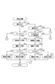
- FIG. 3 is a flowchart showing a processing procedure of inertial running control, and this processing is repeatedly performed by the engine ECU 31 at a predetermined cycle.
- step S11 it is determined whether or not the vehicle 10 is currently in an inertia running state with the clutch off. If YES, the process proceeds to step S12, and if NO, the process proceeds to step S21.
- step S12 it is determined whether or not the brake is on. The brake-on state is determined based on the fact that the brake operation amount detected by the brake sensor 42 is greater than zero. If step S12 is YES, the process proceeds to step S13.
- step S13 the actual deceleration A1 [m / s2] of the vehicle that occurs in response to the driver's brake operation is calculated.
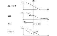
- the actual deceleration A1 is calculated using the relationship of FIG. In FIG. 4, the relationship between the brake operation amount and the deceleration is determined, and the actual deceleration A1 is calculated based on the brake operation amount (the brake pedal depression amount) detected by the brake sensor 42. In this case, a larger value is calculated as the actual deceleration A1 as the brake operation amount is larger.
- a threshold value B1 [m / s2] determined as the deceleration of the vehicle in the accelerator-off and clutch-on state (non-coast deceleration state) is calculated.
- the threshold value B1 is calculated using the correlation data shown in FIG. FIG. 5 shows the same characteristics XA and XB as FIG. 2, and the vertical axis is “deceleration” for convenience.
- the clutch-on-time characteristic XB in FIG. 5 corresponds to correlation data indicating the correlation between the vehicle deceleration in the accelerator-off and clutch-on state and the vehicle speed, and based on the current vehicle speed using this correlation data.
- a threshold value B1 is calculated.
- the threshold value B1 is calculated as a value having a larger deceleration than a threshold value B2 described later.
- step S15 it is determined whether or not the actual deceleration A1 is greater than or equal to the threshold value B1. If A1 ⁇ B1, the process proceeds to step S16, and if A1 ⁇ B1, the process proceeds to step S17. In step S16, it is determined to shift to the clutch-on state, that is, to release the inertia running state. In step S17, it is determined to maintain the clutch-off state, that is, to maintain the coasting state.
- step S21 it is determined whether or not the vehicle 10 is currently in a normal driving state with the clutch on. If YES, the process proceeds to step S22.
- step S22 it is determined whether or not the accelerator is on and the vehicle is in a decelerating state. Whether or not the accelerator is on is determined based on the fact that the accelerator operation amount detected by the accelerator sensor 41 is greater than zero. Whether or not the vehicle is in a deceleration state is determined based on the fact that the vehicle speed detected by the vehicle speed sensor 43 is decreasing. If step S22 is YES, the process proceeds to step S23.
- step S23 the actual deceleration A2 [m / s2] of the vehicle that occurs with a decrease in the accelerator operation amount of the driver is calculated.
- the actual deceleration A2 is calculated using the relationship of FIG. In FIG. 6, the relationship between the accelerator operation amount, the vehicle speed, and the deceleration is determined, and the actual deceleration A2 is calculated based on the accelerator operation amount (accelerator pedal depression amount) detected by the accelerator sensor 41 and the vehicle speed. In this case, a larger value is calculated as the actual deceleration A2 as the accelerator operation amount is smaller or the vehicle speed is larger.
- a threshold value B2 [m / s2] determined as the deceleration of the vehicle in the accelerator-off and clutch-off state (coast deceleration state) is calculated.
- the threshold B2 is calculated using the correlation data shown in FIG.
- the clutch-off characteristic XA in FIG. 5 corresponds to correlation data indicating the correlation between the vehicle deceleration in the accelerator-off and clutch-off states and the vehicle speed, and based on the current vehicle speed using this correlation data.
- a threshold value B2 is calculated.
- step S25 it is determined whether or not the actual deceleration A2 is greater than or equal to the threshold B2. If A2 ⁇ B2, the process proceeds to step S26, and if A2 ⁇ B2, the process proceeds to step S27.
- step S26 it is determined to shift to the clutch-off state, that is, shift to the inertial running state. Further, it is determined to stop the operation of the engine 11 in accordance with the transition to the inertia running state. Alternatively, the engine 11 is shifted to the idle operation state.
- step S27 it is determined to maintain the clutch-on state, that is, to maintain the normal running state.
- the deceleration state of the vehicle 10 becomes “actual deceleration A1 ⁇ threshold B1”.
- the vehicle 10 is decelerated by the braking force according to the brake operation amount.
- the vehicle 10 is decelerated by rotating the engine output shaft on the axle side (so-called engine braking) in addition to the braking force according to the brake operation amount.
- engine braking engine braking
- the brake device at the beginning of the inertial travel cancellation. 28 is intended to limit the braking force. More specifically, when it is determined in step S15 of FIG. 3 that A1 ⁇ B1 and inertial running is released, the engine ECU 31 performs a brake control process shown in FIG.
- step S31 the amount of engine brake generated in the vehicle 10 at the time of releasing inertia running, that is, the time of shifting from clutch-off to clutch-on is estimated.
- the engine brake amount is estimated based on the driving state of the driven device that is drivingly connected to the engine output shaft 12.
- the engine brake amount is estimated based on the driving state of the ISG 13 and the auxiliary machine 15. Further, the engine brake amount may be estimated in consideration of the engine speed after the clutch is turned on, the engine water temperature, and the like.
- step S32 it is determined whether or not the engine brake amount EB is equal to or greater than a predetermined value. If YES, the process proceeds to step S33.
- step S33 the brake force applied by the brake device 28 is limited. At this time, the command brake force is calculated by subtracting the brake force corresponding to the engine brake amount from the basic brake force calculated based on the brake operation amount of the driver. Then, the braking force is applied by the brake device 28 based on the command braking force. Note that step S32 may be omitted.
- FIG. 8 is a time chart showing the brake control of FIG. 7 more specifically.
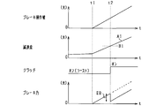
- the brake operation of the driver is started at the timing t1 while the vehicle 10 is coasting, and the deceleration (negative acceleration) of the vehicle 10 gradually increases as the brake operation amount (pedal depression amount) increases.
- the brake operation amount pedal depression amount
- the transition from clutch-off to clutch-on is performed.
- the vehicle 10 is decelerated by the braking force corresponding to the brake operation amount before the timing t2, while the vehicle 10 is decelerated by the engine brake in addition to the braking force after the timing t2.
- the engine brake amount EB is calculated, and the brake force of the brake device 28 is subtracted by an amount corresponding to EB. After timing t2, the braking force of the brake device 28 gradually increases.
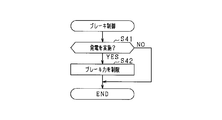
- step S41 it is determined whether or not power generation by the ISG 13 is performed immediately after switching to clutch-on. And if it determines with implementing electric power generation, it will progress to step S42 and the restriction
- a configuration in which the braking force by the brake device 28 is not applied in a period until a predetermined time elapses after the clutch is turned on in other words, a configuration in which the start of applying the braking force is delayed.
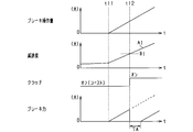
- FIG. 10 is a time chart showing the brake control of FIG. 9 more specifically.
- the driver's braking operation is started at timing t11 while the vehicle 10 is coasting, and the transition from clutch-off to clutch-on is performed at timing t12 when the actual deceleration A1 is greater than the threshold value B1.
- the application of the braking force by the brake device 28 is stopped during the period TA in the figure, and the application of the braking force is started after the passage of TA.
- the configuration may be such that brake control is performed when inertial running is started from the normal running state.
- the deceleration state of the vehicle 10 becomes “actual deceleration A2 ⁇ threshold B2”.
- the vehicle 10 is decelerated by rotating the engine output shaft 12 on the axle side (so-called engine brake).
- engine brake when “actual deceleration A2 ⁇ threshold value B2” is established and the clutch is turned off, the vehicle 10 is decelerated while the braking force for the engine brake is lost. In this case, there is a concern that the deceleration suddenly changes before and after the start of inertial running.
- the engine ECU 31 determines that the actual deceleration A2 is greater than the threshold value B2 during the non-inertial travel, and starts the inertia travel when the inertia travel is started (when step S25 in FIG. 3 is YES).
- the braking force by the brake device 28 is generated regardless of the brake operation by the driver at the beginning of the operation.
- the engine ECU 31 calculates the engine brake amount according to the driving state of the driven devices such as the ISG 13 and the auxiliary machine 15, and adjusts the braking force by the brake device 28 based on the engine brake amount. It is also possible to adjust the braking force of the brake device 28 based on the vehicle speed, taking into account that the deceleration differs according to the vehicle speed.
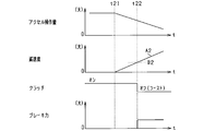
- FIG. 11 is a time chart specifically showing brake control at the start of inertial running.
- the vehicle 10 is decelerated when the driver's accelerator operation is loosened at timing t21 during non-inertial travel of the vehicle 10, and the vehicle 10 is decelerating (decreasing the accelerator operation amount (pedal depression amount)). (Negative acceleration) gradually increases. Then, at the timing t22 when the actual deceleration A2 becomes larger than the threshold value B2, the shift from the clutch on to the clutch off is performed. At this time, the vehicle 10 is decelerated by the engine brake before the timing t22, whereas the vehicle 10 is decelerated after the timing t22 with no engine brake. After the timing t22, the braking force is applied by the brake device 28 to supplement the braking force for the engine brake. Note that the braking force application by the brake device 28 may be performed only for a predetermined period from the timing t22.
- the actual deceleration A1 of the vehicle 10 is compared with a threshold value B1 defined as the deceleration of the vehicle 10 in the accelerator off and clutch on state.
- a threshold value B1 defined as the deceleration of the vehicle 10 in the accelerator off and clutch on state.
- inertial running is canceled.
- the actual deceleration A1 is smaller than the threshold value B1
- coasting is maintained. In this case, it is possible to suppress the frequent occurrence of coasting on / off (switching), and it is possible to expect an improvement in fuel efficiency improvement and an improvement in drivability. As a result, appropriate inertial running control can be realized.
- inertial traveling is canceled on condition that the actual deceleration A1 of the vehicle 10 increases and reaches the threshold value B1 on the characteristic XB. Therefore, fuel injection is required when canceling inertial traveling.
- the desired deceleration can be obtained without any problem, and the fuel consumption can be reduced.
- the vehicle deceleration rate when the accelerator is off and the clutch is on (non-coast deceleration state) varies depending on the vehicle speed. Considering this point, more appropriate inertial traveling control can be realized by calculating the threshold value B1 based on the vehicle speed.
- the braking force by the brake device 28 is limited at the beginning of the inertial traveling cancellation. A sudden change in deceleration at the time of release is suppressed, and as a result, deterioration of drivability can be suppressed.
- the degree of restriction of the braking force by the braking device 28 is adjusted based on the power generation state of the ISG 13 (driving state of the driven device). In this case, it is possible to suppress the generation of excessive braking force on the vehicle 10 due to the regenerative braking force generated by the regenerative power generation while performing the regenerative power generation from the cancellation of inertial running in the vehicle deceleration state. That is, a sudden change in the braking force in the vehicle 10 can be suppressed, and as a result, drivability can be improved.
- the actual deceleration A2 of the vehicle 10 is compared with the threshold value B2 defined as the deceleration of the vehicle 10 in the accelerator-off and clutch-off state in the deceleration state during non-inertial travel (clutch on).
- the threshold value B2 defined as the deceleration of the vehicle 10 in the accelerator-off and clutch-off state in the deceleration state during non-inertial travel (clutch on).
- inertial running is started.
- the threshold value B2 defined as the deceleration of the vehicle 10 in the accelerator-off and clutch-off state in the deceleration state during non-inertial travel (clutch on).
- inertial running is started.
- the threshold value B2 when shifting to the clutch-off state for coasting, an actual deceleration corresponding to the clutch-off state occurs, and the deceleration behavior of the vehicle 10 according to the driver's deceleration request is obtained.
- the actual deceleration A2 is smaller than the threshold value B2, non-iner
- inertial travel is started on the condition that the actual deceleration A2 of the vehicle 10 increases and reaches the threshold value B2 on the characteristic XA. Therefore, fuel injection is required at the start of the inertial travel. Thus, the desired deceleration can be obtained without reducing the fuel consumption.
- the vehicle deceleration rate in the accelerator-off and clutch-off state (coast deceleration state) varies depending on the vehicle speed. Considering this point, more appropriate inertial traveling control can be realized by calculating the threshold B2 based on the vehicle speed.
- the actual deceleration A2 is calculated based on the driver's accelerator operation amount when the vehicle 10 decelerates due to a decrease in the accelerator operation amount during non-inertial travel, it is appropriate while directly reflecting the driver's deceleration request. Inertia running control can be implemented.
- the braking force by the brake device 28 is applied regardless of the brake operation by the driver at the beginning of the inertial travel. Because of this, sudden change in deceleration at the start of inertial running is suppressed, and consequently deterioration in drivability can be suppressed.
- the brake force by the brake device 28 is adjusted based on the driving state of the driven devices such as the ISG 13 and the auxiliary machine 15.
- the engine brake amount differs depending on the drive state of the driven device, it is possible to perform the brake control in consideration of the engine brake amount immediately before the coasting is started. Thereby, the sudden change of the deceleration state in the vehicle 10 can be suppressed, and the improvement of drivability can be aimed at by extension.
- the characteristics XA and XB used for obtaining the threshold values B1 and B2 are defined according to the gear ratio of the transmission 17, a desired inertial traveling control can be realized in consideration of a deceleration state depending on the gear ratio.
- the clutch device 16 is used for each of the case where inertial traveling is canceled during inertial traveling (when switching from clutch off to on) and when inertial traveling is started during normal traveling (when switching from clutch on to off).
- the release and start of inertial running are appropriately controlled. Accordingly, it is possible to appropriately control the release and start timing of inertial travel and the frequency of inertial travel.
- the threshold value B1 of deceleration when releasing inertial traveling is set to a value larger than the threshold value B2 of deceleration when starting inertial traveling, that is, the value of deceleration is large, at the time of releasing and starting inertial traveling, Appropriate inertial running control can be performed while reflecting the clutch off-time characteristic XA and the clutch-on time characteristic XB in the vehicle 10.
- an influence parameter that affects the vehicle deceleration in the accelerator-off state is acquired, and at least one of the actual deceleration and the threshold value during inertial driving is corrected based on the influence parameter.
- the vehicle 10 also corrects at least one of the actual deceleration and the threshold value during non-inertial traveling based on the influence parameter.
- the deceleration rate when the accelerator is off in the vehicle 10 becomes small.
- the deceleration characteristics of the vehicle 10 are affected, and as shown in FIG. 12A, the deceleration characteristics change from basic characteristics XA and XB indicated by solid lines to characteristics XA1 and XB1 indicated by broken lines. .
- the deceleration rate when the accelerator is off in the vehicle 10 increases.
- the deceleration characteristics of the vehicle 10 are also affected, and as shown in FIG. 12B, the deceleration characteristics are changed from the basic characteristics XA and XB indicated by the solid lines to the characteristics XA2 and XB2 indicated by the alternate long and short dash lines. Change.
- the downward slope corresponds to a factor that decreases the deceleration of the vehicle 10
- the upward slope corresponds to a factor that increases the deceleration of the vehicle 10.
- the actual decelerations A1, A2 and the threshold values B1, B2 are corrected in consideration of the change in the deceleration characteristic in this way, and the actual decelerations A1, A2 and threshold values B1, B2 after the correction are used, The size comparison is performed.
- the influence parameter corresponds to at least one of the state of the vehicle and the driving environment. Specifically, (1) road inclination, (2) road surface condition, (3) driving resistance, (4) number of passengers / It is possible to use parameters such as loading weight and (5) change over time. Among these, the road inclination of (1) can be detected by the inclination angle sensor 44. Each of (2) to (5) can be directly detected by a sensor or the like, but in addition to acquiring information by sensor detection, it is possible to acquire information in a predetermined stable running state. . For example, when the vehicle is traveling on a flat road with the accelerator off and the brake off and no gradient, information is acquired by comparison with a reference value.
- each of the above parameters affects the vehicle deceleration (in other words, increase / decrease in vehicle deceleration), and the value of each parameter corresponds to a value that reduces the deceleration as in downhill driving. If so, the actual decelerations A1 and A2 and the threshold values B1 and B2 are calculated using the characteristics XA1 and XB1 (characteristics whose deceleration is smaller than the basic characteristics XA and XB) shown in FIG. Further, if the value of each parameter corresponds to a value that increases the deceleration as in uphill running, the characteristics XA2 and XB2 shown in FIG. 12B (the deceleration is lower than the basic characteristics XA and XB). Actual decelerations A1 and A2 and threshold values B1 and B2 are calculated using a large characteristic). The actual deceleration and the threshold value are corrected by such arithmetic processing.
- FIG. 13 is a flowchart showing a processing procedure of inertial running control, and this processing is repeatedly performed at a predetermined cycle by the engine ECU 31 in place of FIG. 3 described above.
- the same steps as those in FIG. The changes from the processing of FIG. 3 are the addition of steps S51 and S52 and the change of the processing contents of steps S13, S14, S23, and S24.
- step S51 the first parameter is acquired as the influence parameter.
- the first parameter is at least one of the above (1) to (5).
- step S13 the actual deceleration A1 [m / s2] of the vehicle caused by the driver's braking operation is calculated, and in the subsequent step S14, the threshold value B1 [m / s2] is calculated.
- the actual deceleration A1 and the threshold value B1 are calculated in consideration of the change in the deceleration characteristics as shown in FIGS. 12A and 12B according to the first parameter.
- step S52 the second parameter is acquired as the influence parameter.
- the second parameter is at least one of the above (1) to (5).
- the first parameter and the second parameter may be integrated to be a common parameter.
- step S23 the actual deceleration A2 [m / s2] of the vehicle that occurs as the driver's accelerator operation amount decreases is calculated, and in step S24, the threshold B2 [m / s2] is calculated. At this time, the actual deceleration A2 and the threshold B2 are calculated considering that the deceleration characteristics change as shown in FIGS.
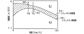
- the region between the characteristic XB is an inertial traveling region in which the vehicle 10 performs inertial traveling, and inertial traveling is started when the deceleration rate of the vehicle 10 changes from outside the inertial traveling region (Y2, Y4). )
- the inertia running is canceled (Y1, Y3). Note that “Y1, Y2” corresponds to the state transition described in the first embodiment.
- symbol ACC is an accelerator pedal
- symbol BR is a brake pedal
- Y1 is a case where the amount of brake operation increases in a vehicle deceleration state during inertial traveling.
- inertial traveling is accompanied by a state transition from a region where the deceleration is smaller than a region where the deceleration is smaller than the clutch-on characteristic XB. Is released.
- Y2 is a case where the accelerator operation amount decreases in the vehicle deceleration state in the non-inertial traveling, and in such a case, along with the state transition from the region where the deceleration is smaller than the clutch-off characteristic XA, the inertia Traveling starts.
- Y3 is a case where the accelerator operation amount increases in a vehicle deceleration state in inertial traveling.
- inertial traveling is accompanied by a state transition from a region where the deceleration is larger than a region where the deceleration is smaller than the clutch-off characteristic XA. Is released.
- Y4 is a case where the brake operation amount decreases in the vehicle deceleration state in the non-inertial traveling.
- the inertia is accompanied by the state transition from the region where the deceleration is larger than the region when the clutch-on characteristic XB is larger to the smaller region. Traveling starts.
- FIGS. 16 and 17 are flowcharts showing a process procedure of inertial running control, and this process is repeatedly performed by the engine ECU 31 at a predetermined cycle.
- steps S11 to S17 and steps S21 to S27 are the same as those in FIG. 3 described above, and will not be described in detail.
- the difference from FIG. 3 is that when the vehicle is coasting and the brake is not on (when S11 is YES and S12 is NO), the process shifts to another process, and the vehicle is traveling normally and the accelerator is on.
- S11 is YES and S12 is NO
- step S61 it is determined whether or not the accelerator is on and the vehicle is in a decelerating state. This determination is performed based on the detection result of the accelerator sensor 41 and the detection result of the vehicle speed sensor 43, as in step S22. If step S61 is YES, the process proceeds to step S62.
- step S62 the actual deceleration A3 [m / s2] of the vehicle occurring when the accelerator operation amount of the driver is increased is calculated.
- the actual deceleration A3 is calculated using the relationship shown in FIG. In FIG. 18, the relationship between the accelerator operation amount, the vehicle speed, and the deceleration is determined, and the actual deceleration A3 is calculated based on the accelerator operation amount (accelerator pedal depression amount) detected by the accelerator sensor 41 and the vehicle speed. In this case, the smaller the accelerator operation amount or the smaller the vehicle speed, the smaller the actual deceleration A3 is calculated.
- the relationship in FIG. 18 is the same as the relationship shown in FIG. 6 for obtaining the actual deceleration A2. However, the relationship in FIG. 18 may be different from the relationship in FIG. 6. For example, when comparing with the same accelerator operation amount and vehicle speed, the actual deceleration A3 is made larger or smaller than the actual deceleration A2. Is possible.
- a threshold value B3 [m / s2] determined as the deceleration of the vehicle in the accelerator-off and clutch-off state (coast deceleration state) is calculated.
- the threshold value B3 is calculated based on the vehicle speed using the correlation data shown in FIG.
- step S64 it is determined whether or not the actual deceleration A3 is equal to or less than the threshold value B3. If A3 ⁇ B3, the process proceeds to step S65, and if A3> B3, the process proceeds to step S66.
- step S65 it is determined to shift to the clutch-on state, that is, to release the inertia running state. At this time, by starting the operation of the engine 11 (fuel injection), it is possible to achieve a deceleration rate in a deceleration range that is looser than the clutch-off characteristic XA, that is, a deceleration rate that cannot be obtained in the inertial running state. It has become.
- the process of step S65 corresponds to the above “Y3”.
- step S66 it is determined to maintain the clutch-off state, that is, to maintain the coasting state.
- step S71 it is determined whether or not the brake is on. This determination is performed based on the detection result of the brake sensor 42 as in step S12. If step S71 is YES, the process proceeds to step S72.
- step S72 the actual deceleration A4 [m / s2] of the vehicle that is caused by the driver's brake operation is calculated.
- the actual deceleration A4 is calculated using the relationship of FIG. In FIG. 20, the relationship between the brake operation amount and the deceleration is determined, and the actual deceleration A4 is calculated based on the brake operation amount (the brake pedal depression amount) detected by the brake sensor 42. In this case, a smaller value is calculated as the actual deceleration A4 as the brake operation amount is smaller.
- the relationship of FIG. 20 is the same as the relationship of FIG. 4 for obtaining the actual deceleration A1.
- the relationship of FIG. 20 may be different from the relationship of FIG. 4.
- the actual deceleration A4 can be made larger or smaller than the actual deceleration A1. It is.
- a threshold value B4 [m / s2] determined as the deceleration of the vehicle in the accelerator-off and clutch-on state (non-coast deceleration state) is calculated. Specifically, the threshold value B4 is calculated based on the vehicle speed using the correlation data shown in FIG.
- step S74 it is determined whether or not the actual deceleration A4 is equal to or less than the threshold value B4. If A4 ⁇ B4, the process proceeds to step S75, and if A4> B4, the process proceeds to step S76.
- step S75 it is determined to shift to the clutch-off state, that is, to shift to the inertial running state. Further, it is determined to stop the operation of the engine 11 in accordance with the transition to the inertia running state. Alternatively, the engine 11 is shifted to the idle operation state.
- the process in step S75 corresponds to the above “Y4”.
- step S76 it is determined to maintain the clutch-on state, that is, to maintain the normal running state.
- brake assist is performed by the brake device 28 while taking into account the stop of the engine brake.
- step S81 the engine brake amount of the vehicle 10 that is lost with the start of inertial running is estimated.
- the engine brake amount is estimated based on the driving state of the driven device that is drivingly connected to the engine output shaft 12.
- the engine brake amount is estimated based on the driving state of the ISG 13 and the auxiliary machine 15. Further, the engine brake amount may be estimated in consideration of the engine rotation speed before clutch-off, the engine water temperature, and the like.
- step S82 it is determined whether or not the engine brake amount EB is equal to or greater than a predetermined value. If YES, the process proceeds to step S83.
- step S83 the brake device 28 additionally applies a braking force to perform brake assist. At this time, the command brake force is calculated by adding the brake force corresponding to the engine brake amount to the basic brake force calculated based on the brake operation amount of the driver. Then, the braking force is applied by the brake device 28 based on the command braking force. Note that step S82 can be omitted.
- FIG. 22 is a time chart showing the brake control of FIG. 21 more specifically.
- the brake operation by the driver is performed during the normal traveling of the vehicle 10 in the clutch-on state before the timing t31, and the basic braking force corresponding to the brake operation amount (pedal depression amount) is applied to the vehicle 10. And deceleration according to the engine braking force. Further, the amount of brake operation by the driver is reduced with the passage of time, and the deceleration (negative acceleration) of the vehicle 10 is gradually reduced accordingly.
- step S91 it is determined whether or not power generation by the ISG 13 is performed before the start of coasting. If it is determined that power generation is being performed, the process proceeds to step S92, where the brake device 28 additionally applies a brake force to perform brake assist. At this time, it is preferable to brake assist the sum of the engine brake and the power generation brake (power generation load).
- FIG. 24 is a time chart showing the brake control of FIG. 23 more specifically.
- a brake operation by the driver is performed during normal traveling of the vehicle 10 in the clutch-on state, and the vehicle 10 has a basic braking force corresponding to a brake operation amount (a pedal depression amount) and The engine braking force and the braking force corresponding to the power generation load of the ISG 13 are generated.
- the amount of brake operation by the driver is reduced with the passage of time, and the deceleration (negative acceleration) of the vehicle 10 gradually decreases accordingly.
- the shift from the clutch on to the clutch off is performed.
- the braking force between the engine brake and the power generation load is lost as the clutch is turned off.
- the brake force for the lost amount is additionally applied by the brake device 28, the change (abrupt change) in the deceleration rate of the vehicle 10 before and after the timing t41 is suppressed.
- inertial running is started or canceled with the decrease or increase of the brake operation amount (in the case of “Y1, Y4”)
- the inertial running is started or canceled with the decrease or increase of the accelerator operation amount In the case of “Y2, Y3”, brake control or torque assist control may be performed.
- the engine ECU 31 estimates the engine brake amount according to the vehicle speed at the end of inertial traveling, the gear ratio of the transmission 17, the engine rotation speed, and the like, and calculates the torque assist amount by the ISG 13 based on the engine brake amount. adjust.
- FIG. 25 is a time chart specifically showing torque control at the end of inertial running.
- the deceleration (negative acceleration) of the vehicle 10 gradually decreases as the accelerator operation amount (pedal depression amount) by the driver increases in the vehicle deceleration state during inertial running.
- the transition from clutch-off to clutch-on is performed.
- engine brake is not generated before timing t51, whereas engine brake is generated at timing t51.
- torque assist by the ISG 13 is performed in order to cancel out the deceleration caused by the engine brake.
- torque assist by the ISG 13 may be performed only for a predetermined period from the timing t51. Further, it is preferable that the torque assist amount is gradually reduced as time elapses.
- the actual deceleration A3 of the vehicle 10 is compared with a threshold B3 defined as the deceleration of the vehicle 10 in the accelerator-off and clutch-off state. If it is smaller than the threshold value B3, inertial running is canceled (corresponding to Y3 in FIG. 14). In this case, when shifting to the clutch-on state in order to cancel inertial running, an actual deceleration corresponding to the clutch-on state occurs, and the deceleration behavior of the vehicle 10 according to the driver's deceleration request is obtained. Further, when the actual deceleration A3 is smaller than the threshold value B3, inertial running is maintained. In this case, it is possible to suppress the frequent occurrence of coasting on / off (switching), and it is possible to expect an improvement in fuel efficiency improvement and an improvement in drivability. As a result, appropriate inertial running control can be realized.
- inertial traveling is released on condition that the actual deceleration A3 of the vehicle 10 decreases and reaches the threshold value B3 on the characteristic XA. This makes it possible to achieve a deceleration rate with no deceleration area. As a result, a desired deceleration rate can be realized.
- the vehicle deceleration rate in the accelerator-off and clutch-off state (coast deceleration state) varies depending on the vehicle speed. Considering this point, more appropriate inertial traveling control can be realized by calculating the threshold value B3 based on the vehicle speed.
- the actual deceleration A4 of the vehicle 10 is compared with the threshold value B4 defined as the deceleration of the vehicle 10 in the accelerator-off and clutch-on state in the deceleration state during non-inertial travel (clutch-on).
- the threshold value B4 defined as the deceleration of the vehicle 10 in the accelerator-off and clutch-on state in the deceleration state during non-inertial travel (clutch-on).
- inertial running is started (corresponding to Y4 in FIG. 14).
- the actual deceleration A4 is larger than the threshold value B4, non-inertial running is maintained. In this case, it is possible to suppress frequent on / off (switching) of inertial running, and an improvement in fuel efficiency improvement and an improvement in drivability can be expected. As a result, it is possible to achieve appropriate inertial running control.
- inertial travel is started on the condition that the actual deceleration A4 of the vehicle 10 becomes smaller and reaches the threshold value B4 on the characteristic XB.
- the desired deceleration can be realized by the braking force based on the brake operation amount.
- the vehicle deceleration rate in the accelerator-off and clutch-on state (coast deceleration state) varies depending on the vehicle speed. Considering this point, more appropriate inertial traveling control can be realized by calculating the threshold value B4 based on the vehicle speed.
- the braking force by the brake device 28 is changed to the brake operation amount by the driver at the beginning of the inertial travel. It was made to increase rather than the braking force based. Therefore, a sudden change in deceleration at the start of inertial running is suppressed, and as a result, deterioration in drivability can be suppressed.
- the brake force by the brake device 28 is adjusted in the initial period based on the driving state of the driven devices such as the ISG 13 and the auxiliary machine 15 (power generation state of the ISG 13 and the like).
- the engine brake amount differs depending on the drive state of the driven device, it is possible to perform the brake control in consideration of the engine brake amount immediately before the coasting is started. Thereby, the sudden change of the deceleration state in the vehicle 10 can be suppressed, and the improvement of drivability can be aimed at by extension.
- the characteristics XA and XB used for obtaining the threshold values B3 and B4 are defined according to the gear ratio of the transmission 17, a desired inertial traveling control can be realized in consideration of the deceleration state depending on the gear ratio.
- the clutch device 16 is used for each of the case where inertial traveling is canceled during inertial traveling (when switching from clutch off to on) and when inertial traveling is started during normal traveling (when switching from clutch on to off).
- the release and start of inertial running are appropriately controlled. Accordingly, it is possible to appropriately control the release and start timing of inertial travel and the frequency of inertial travel.
- the deceleration threshold B3 when canceling inertial traveling is set to a value smaller than the deceleration threshold B4 when inertial traveling is started, that is, the value of the deceleration is small, at the time of canceling and starting inertial traveling, Appropriate inertial running control can be performed while reflecting the clutch off-time characteristic XA and the clutch-on time characteristic XB in the vehicle 10.
- the influence parameter corresponds to at least one of the state of the vehicle and the traveling environment. Specifically, (1) road inclination, (2) road surface state, (3) traveling resistance, (4 It is possible to use parameters such as :) number of passengers / loading weight, and (5) change over time.
- Each of the above parameters affects the vehicle deceleration. If the value of each parameter corresponds to a value that reduces the deceleration as in downhill running, characteristics XA1, XB1 (characteristics in which the deceleration is smaller than the basic characteristics XA, XB) shown in FIG. ) To calculate actual decelerations A3 and A4 and threshold values B3 and B4. Further, if the value of each parameter corresponds to a value that increases the deceleration as in uphill running, the characteristics XA2 and XB2 shown in FIG. 12B (the deceleration is lower than the basic characteristics XA and XB). Actual decelerations A3 and A4 and threshold values B3 and B4 are calculated using a large characteristic). The actual deceleration and the threshold value are corrected by such arithmetic processing.
- FIG. 26 is a flowchart showing a processing procedure of inertial running control, and this processing is an alternative to the above-described FIG. 17 and is repeatedly performed by the engine ECU 31 at a predetermined cycle.
- the same steps as those in FIG. Changes from the processing in FIG. 17 are addition of steps S101 and S102 and changes in the processing contents of steps S62, S63, S72, and S73.
- step S101 when the vehicle 10 is in the inertial running state and is in the accelerator-on deceleration state (when step S61 is YES), the process proceeds to step S101.
- step S101 at least one of the above (1) to (5) is acquired as an influence parameter.
- step S62 the actual deceleration A3 [m / s2] of the vehicle that occurs as the driver's accelerator operation amount increases is calculated, and in step S63, the threshold B3 [m / s2] is calculated.
- the actual deceleration A3 and the threshold B3 are calculated considering that the deceleration characteristics change as shown in FIGS. 12A and 12B according to the influence parameter. It is also possible to add an influence parameter (perform correction) for one of the actual deceleration A3 and the threshold B3. Thereafter, based on the actual deceleration A3 and the threshold value B3, it is determined to cancel or maintain the inertia running (steps S64 to S66).
- step S102 at least one of the above (1) to (5) is acquired as the influence parameter.
- step S72 the actual deceleration A4 [m / s2] of the vehicle caused by the driver's braking operation is calculated, and in the subsequent step S73, the threshold value B4 [m / s2] is calculated.
- the actual deceleration A4 and the threshold B4 are calculated considering that the deceleration characteristics change as shown in FIGS. 12A and 12B according to the influence parameter.
- the deviation amount of the deceleration from the basic characteristics XA and XB is calculated, and the actual decelerations A3 and A4 and the threshold values B3 and B4 are corrected based on the deviation amount. Also good.
- the amount of brake operation increases rapidly in a state where the deceleration rate is smaller than the clutch-off characteristic XA, and changes from the region R1 where the deceleration rate is smaller than the inertia traveling region to the region R2 where the deceleration rate is larger than the inertia traveling region. Change has occurred. In this case, the deceleration rate changes through the inertial running area. Therefore, in the vehicle deceleration state in the non-inertial state, even if the actual deceleration rate of the vehicle 10 is greater than the threshold value determined based on the clutch-off characteristic XA and enters the inertial traveling region, the normal traveling to the inertial traveling is performed. No state change will occur.
- the accelerator operation amount increases rapidly in a state where the deceleration rate is larger than the clutch-on-time characteristic XB, and the region R2 where the deceleration rate is larger than the inertia traveling region changes to the region R1 where the deceleration rate is smaller than the inertia traveling region. Change has occurred. In this case as well, the deceleration rate changes through the inertial running area. Therefore, in the vehicle deceleration state in the non-inertial state, even if the actual deceleration rate of the vehicle 10 becomes smaller than the threshold value determined based on the clutch-on characteristic XB and enters the inertial traveling region, the normal traveling to the inertial traveling is performed. No state change will occur.
- the engine ECU 31 starts coasting when the deceleration of the vehicle 10 is in the region R1 and the vehicle deceleration enters the coasting travel region due to a decrease in the brake operation amount or the like.
- the deceleration amount of the vehicle 10 is in the region R2
- the vehicle deceleration amount enters the inertia traveling region due to an increase in the accelerator operation amount or the like, the inertia traveling is started.
- FIG. 28 is a flowchart showing a processing procedure of inertial running control, and this processing is repeatedly performed by the engine ECU 31 at a predetermined cycle.
- FIG. 28 only processing corresponding to the state changes of Y5 and Y6 is shown, and processing corresponding to the state changes of Y1 to Y4 is performed separately.
- step S111 it is determined whether or not the vehicle 10 is currently in a normal travel (non-inertial travel) state. If YES, the process proceeds to step S112. In step S112, it is determined whether or not the vehicle deceleration rate is in the deceleration region of R1 in FIG. 27. In step S113, it is determined whether or not the vehicle deceleration rate is in the deceleration region of R2 in FIG. At this time, if step S112 is YES, the process proceeds to step S114, and if step S113 is YES, the process proceeds to step S118.
- step S112 determines that the actual deceleration in the non-inertial running state is in a region (R1) that is smaller than the clutch off-time characteristic XA.
- step S113 determines that the actual deceleration in the non-inertial running state is in a region (R2) that is greater than the clutch-on characteristic XB.
- step S114 it is determined whether or not the deceleration of the vehicle 10 is increased by the driver's brake operation. This may be determined, for example, based on whether or not the brake operation amount has increased. If the deceleration rate increases, the process proceeds to the subsequent step S115. If the deceleration rate does not increase, the process ends.
- step S115 in a state where the vehicle deceleration rate is increased by the driver's brake operation, it is determined whether or not the actual deceleration rate changed by the brake operation is larger than a threshold value B5 determined based on the clutch-on characteristic XB. To do.
- FIG. 27 illustrates the threshold value B5.
- step S115 is affirmed.
- the threshold value B5 may be obtained based on the brake operation amount and the vehicle speed.
- step S115 YES, it will progress to step S116 and will determine that normal driving
- step S118 it is determined whether or not the deceleration of the vehicle 10 is reduced by the driver's accelerator operation. This may be determined, for example, based on whether or not the accelerator operation amount has increased. If the deceleration rate is in a decreasing state, the process proceeds to the subsequent step S119. If the deceleration rate is not in a decreasing state, the process is terminated.
- step S119 in a state where the vehicle deceleration rate is reduced by the driver's accelerator operation, it is determined whether or not the actual deceleration rate changed by the accelerator operation is smaller than a threshold value B6 determined based on the clutch off-time characteristic XA.
- FIG. 27 illustrates the threshold B6, and when it is determined in FIG. 27 that the state transition from the region R2 to the region R1 is made, step S119 is affirmed.
- the threshold value B6 may be obtained based on the accelerator operation amount and the vehicle speed.
- step S119 YES, it will progress to step S120 and will determine that normal driving
- the brake operation by the driver is performed and changes depending on the brake operation in a state where the actual deceleration in the non-inertial traveling state is in the region R1 where the deceleration rate is smaller than the inertia traveling region.
- Non-inertial running is maintained when the actual deceleration rate is greater than the clutch-on threshold (B5).
- the accelerator operation by the driver is performed, and the actual deceleration rate that changes due to the accelerator operation is the clutch.
- Non-inertial running is maintained when it is smaller than the off threshold (B6).
- FIG. 29 is obtained by changing a part of FIG.
- changes in Y1 and Y2 occur with an increase in vehicle deceleration.
- the increase in vehicle deceleration is caused by an increase in the brake operation amount by the driver or a decrease in the accelerator operation amount.
- the changes in Y3 and Y4 are caused by a decrease in the vehicle deceleration, and the decrease in the vehicle deceleration is caused by an increase in the accelerator operation amount by the driver or a decrease in the brake operation amount.
- the inertial traveling is started by increasing the actual deceleration as the amount of brake operation by the driver increases during non-inertial traveling (corresponding to Y2).
- the inertia traveling may be canceled by reducing the actual deceleration with a decrease in the brake operation amount by the driver during inertia traveling (corresponding to Y3).
- the inertial traveling is started by reducing the actual deceleration as the accelerator operation amount by the driver increases during non-inertial traveling (corresponding to Y4).
- the inertia traveling may be canceled by increasing the actual deceleration accompanying the decrease in the accelerator operation amount by the driver during inertia traveling (corresponding to Y1).
- the engine ECU 31 performs inertial running control in order to realize the state changes of Y1 to Y4.
- the inertial running is canceled, and if it is determined that the actual deceleration rate is smaller than the threshold value, the inertial running is maintained (corresponding to Y1).
- (C) During inertial running, when it is determined that the actual deceleration calculated based on the brake operation amount (operation amount when the brake is reduced) is smaller than the threshold calculated based on the clutch-off characteristic XA In addition, the inertial running is canceled and the inertial running is maintained when it is determined that the actual deceleration rate is larger than the threshold value (corresponding to Y3).
- (D) During non-inertial travel, it is determined that the actual deceleration calculated based on the accelerator operation amount (the operation amount when the accelerator increases) is smaller than the threshold calculated based on the clutch-on-time characteristic XB. In this case, coasting is started, and when it is determined that the actual deceleration rate is larger than the threshold, the coasting is maintained (corresponding to Y4).
- the engine ECU 31 determines whether the traveling path of the vehicle 10 is a slope, and further, whether it is a downhill or an uphill. Based on the determination result, the above-described (a) to (d) Processing may be performed.
- FIG. 30 may be configured to use the relationship shown in FIG. 30 when calculating the actual vehicle decelerations A1 and A4 caused by the driver's braking operation.
- the relationship between the brake operation amount, the vehicle speed, and the deceleration is determined. According to this relationship, the greater the brake operation amount or the greater the vehicle speed, the larger the actual decelerations A1 and A4. Calculated. The same applies when the processing based on FIG. 29 is performed.
- the brake assist amount is gradually reduced as time elapses from the start of inertial running.
- the brake assist amount is gradually reduced as time elapses from the start of inertial running.
- the brake assist it is possible to shift the deceleration of the vehicle 10 after the start of inertial running to a situation where the driver's accelerator operation is left without performing brake assist while suppressing deterioration of drivability.
- the influence parameter may include the wind direction. That is, whether the tail wind is blowing or the head wind is blowing in the traveling direction of the vehicle is set as the influence parameter.
- the tailwind corresponds to a factor that decreases the vehicle deceleration
- the headwind corresponds to a factor that increases the vehicle deceleration. It is also possible to include wind speed in the influence parameter.
- the influence parameter may be obtained as follows. That is, the engine ECU 31 uses the reference deceleration amount obtained based on the accelerator operation amount or the brake operation amount and the vehicle speed as an influence parameter for reducing or increasing the vehicle deceleration amount, and the actual deceleration obtained from the actually measured speed information. Get the amount of deviation from the degree.
- the relationship shown in FIG. 33 is defined as a correlation map that defines the reference deceleration rate under the reference travel condition of the vehicle 10.
- the engine ECU 31 acquires a deviation amount ⁇ X between a reference deceleration (for example, P1 in FIG. 33) obtained by each condition on the correlation map and an actually measured vehicle deceleration (for example, P2 in FIG. 33).
- the engine ECU 31 also uses the threshold value B1 (or threshold value B4) calculated using the clutch-on time characteristic XB or the threshold value B2 (or threshold value B3) calculated using the clutch-off time characteristic XA based on the deviation amount ⁇ X. ) Is corrected.
- the actual decelerations A1 to A4 can be corrected based on the deviation amount ⁇ X.
- the actual measured value of the vehicle deceleration may be obtained from the detected value of the acceleration sensor or the differential value of the detected value of the vehicle speed sensor.
- the deviation amount ⁇ X may be obtained when the vehicle 10 is not coasting.
- the start and release of inertial running are appropriately controlled while taking into account the deviation amount ⁇ X of deceleration actually generated in use in the vehicle 10, that is, the amount of deviation from the reference value caused by various conditions in each case. can do.
- the thresholds B1 and B4 are calculated as the deceleration on the clutch-on characteristic XB, and the thresholds B2 and B3 are calculated as the deceleration on the clutch-off characteristic XA.
- the threshold values B1 to B4 may be calculated as values smaller or larger than the characteristics XA and XB. That is, the threshold values B1 and B4 may be determined based on the clutch-on time characteristic XB, and the threshold values B2 and B3 may be determined based on the clutch-off time characteristic XA.
- the clutch-off characteristic XA and the clutch-on characteristic XB are determined in consideration of the shift stage of the multi-stage transmission. Good. For example, a plurality of characteristics XA and XB may be determined for each gear position.
- the actual decelerations A1 and A4 are calculated as the actual deceleration rate in the coasting deceleration state based on the brake operation amount that is the brake pedal depression amount, but this may be changed.
- the actual decelerations A1 and A4 are calculated based on the pressure applied by the driver's brake operation (brake hydraulic pressure of the brake device 28) and the depression speed of the brake pedal. Also good. In this case, what is necessary is just the structure which calculates actual deceleration A1, A4 based on the embodiment of brake operation.
- an embodiment of the accelerator operation may be determined based on a parameter other than the accelerator operation amount that is the accelerator pedal depression amount, and the actual decelerations A2 and A3 may be calculated based on the embodiment.
- the actual decelerations A2 and A3 are calculated based on the elapsed time from the start of the decrease in the accelerator operation amount.
- ⁇ A configuration may be used in which the actual deceleration of the vehicle in the coasting deceleration state is calculated without using the parameters related to the driver's brake operation.
- the actual deceleration rate is calculated based on the change in the vehicle speed while the vehicle is coasting.
- the actual deceleration is calculated from the differential value of the actual vehicle speed detected by the vehicle speed sensor 43, and the actual deceleration is compared with a predetermined threshold value.
- the configuration may be such that the actual deceleration of the vehicle in the non-coast deceleration state is calculated without using the parameter relating to the driver's accelerator operation.
- the actual deceleration rate is calculated based on a decrease change in the vehicle speed during normal traveling of the vehicle.
- the actual deceleration is calculated from the differential value of the actual vehicle speed detected by the vehicle speed sensor 43, and the actual deceleration is compared with a predetermined threshold value.
- calculation processing for canceling inertial driving based on the comparison between the actual deceleration A1 and the threshold value B1, and calculation for canceling inertial driving based on simply performing a brake operation without performing the comparison The structure which switches a process may be sufficient.
- calculation processing for starting inertial travel based on the comparison between the actual deceleration A2 and the threshold value B2, and starting inertial travel based on simply releasing the accelerator operation without performing the comparison It may be configured to switch between arithmetic processing to be performed.
- calculation processing for canceling inertial traveling based on the comparison between the actual deceleration A3 and the threshold B3, and inertial traveling is canceled based on simply performing an accelerator operation without performing the comparison. It may be configured to switch between arithmetic processing. Further, during non-inertial travel, calculation processing for starting inertial travel based on the comparison between the actual deceleration A4 and the threshold value B4, and starting inertial travel based on simply releasing the brake operation without performing the comparison It may be configured to switch between arithmetic processing to be performed.
- the transition from the normal travel to the inertia travel and the transition from the inertia travel to the normal travel are determined.
- this may be changed.
- the actual decelerations A1 and A4 and the threshold values B1 and B1 are replaced with the actual brake operation amount and the operation amount threshold value, and the actual brake operation amount and the operation amount threshold value are compared.
- the actual deceleration A2 and A3 and the thresholds B2 and B3 are replaced with the actual accelerator operation amount and the operation amount threshold, and a comparison is made between the actual accelerator operation amount and the operation amount threshold.
- the control for canceling and starting inertial running is adopted. However, it may be configured to change this and perform only one of the control when the inertia traveling is canceled during the inertia traveling and the control when the inertia traveling is started during the normal traveling. .
Abstract
車両制御装置は、所定の実施条件の成立に応じて、クラッチをオフにして車両を惰性走行状態とし、惰性走行中における所定の解除条件の成立に応じて、クラッチをオンにして惰性走行状態を解除する。車両制御装置は減速度合算出手段と、判定手段と、走行制御手段と、を備える。減速度合算出手段は惰性走行での車両減速状態において、車両の減速度合である実減速度合を算出し、判定手段は減速度合算出手段により算出された実減速度合が、アクセルオフかつクラッチオンの状態での車両の減速度合に基づき定められる閾値よりも大きいか否かを判定し、走行制御手段は実減速度合が閾値よりも大きいと判定された場合に、惰性走行を解除し、実減速度合が閾値よりも小さいと判定された場合に、惰性走行を維持する。
Description
本開示は、車両制御装置に関する。より詳しくは、車両の惰性走行の制御を行う制御装置に関する。
近年、車両の惰性走行に関する技術が開発されている。詳しくは、燃費改善等を目的として、車両走行中のアクセルオフ時に、エンジンと変速機との間に設けたクラッチ装置を遮断状態にして車両を惰性走行状態にする技術が実用化されている。例えば、特開2011-219087号公報(特許文献1)などでは、さまざまな惰性走行に関する技術が提案されている。
既存の技術では、車両の惰性走行中においてドライバによりブレーキ操作やアクセル操作が行われると、それにより直ちに惰性走行状態が解除され、通常走行状態への復帰が行われる。この場合、惰性走行の解除に際してはクラッチオフからクラッチオンへの切替が生じ、その切替に伴い車両において減速度合の変化に起因する減速ショックが生じること等が懸念される。また、ドライバの意向に反して惰性走行状態が解除されることがあると、期待するほどの燃費を改善する効果が得られなくなることが考えられる。さらに、惰性走行の開始及び終了に伴うクラッチ装置の断続(オン/オフ)が頻繁に生じることで、車両のドライバビリティに影響が及ぶことが懸念される。
また、車両の通常走行状態から惰性走行が開始される場合にも、やはり惰性走行の開始に際してクラッチオンからクラッチオフへの切替が生じ、その切替に伴い車両において減速度合の変化に起因する減速ショックが生じること等が懸念される。
また、車両が減速される場合には、クラッチ装置のオンオフの状態や車両減速状態での燃料噴射の状態に応じて、車両に生じる減速度が相違する。この場合、惰性走行を実施する領域に応じて燃料消費の状態に影響が及ぶため、この点についても検討の余地があると考えられる。
本開示は上記事情を鑑みてなされたものであり、その主たる目的は、適正なる惰性走行制御を実現することができる車両制御装置を提供することにある。
以下、上記課題を解決するための手段、及びその作用効果について説明する。なお以下においては、理解の容易のため、本開示の実施の形態において対応する構成の符号を括弧書き等で適宜示すが、この括弧書き等で示した具体的構成に限定されるものではない。
本開示の車両制御装置は、走行駆動源としてのエンジン(11)と、該エンジンの出力軸(12)に繋がる動力伝達経路に設けられるクラッチ装置(16)とを備える車両(10)に適用され、所定の実施条件の成立に応じて、前記クラッチ装置を遮断状態にして前記車両を惰性走行状態とし、惰性走行中における所定の解除条件の成立に応じて、前記クラッチ装置を接続状態にして惰性走行状態を解除するものである。
そして、車両制御装置は、惰性走行での車両減速状態において、その際の車両の減速度合である実減速度合(A1)を算出する減速度合算出手段と、前記減速度合算出手段により算出された実減速度合が、アクセル操作が無くかつ前記クラッチ装置が接続された状態での車両の減速度合に基づき定められる閾値(B1)よりも大きいか否かを判定する判定手段と、前記実減速度合が前記閾値よりも大きいと判定された場合に、惰性走行を解除し、前記実減速度合が前記閾値よりも小さいと判定された場合に、惰性走行を維持する走行制御手段と、を備えることを特徴とする。なお本構成は、図14の「Y1」に相当する構成である。
車両が惰性走行状態(クラッチ遮断状態)で減速している場合において、その走行状態でクラッチ接続状態になることを仮想すると、車両の減速度合が変化する。つまり、クラッチ接続状態では、エンジンの引きずりトルク(いわゆるエンジンブレーキ)による減速が生じるため、クラッチ接続状態の方がクラッチ遮断状態よりも減速度合が大きくなると考えられる。ゆえに、惰性走行を解除して非惰性走行に移行する場合には、クラッチ遮断状態とクラッチ接続状態との減速度の違いを考慮することが好ましい。
この点、上記構成では、惰性走行(クラッチ遮断)での車両減速状態における車両の実減速度合(A1)と、アクセルオフかつクラッチ接続の状態での車両の減速度合に基づき定められる閾値(B1)とを比較し、実減速度合が閾値よりも大きい場合には、惰性走行を解除するようにした。この場合、惰性走行解除のためにクラッチ接続状態に移行する時点では、そのクラッチ接続状態に見合う実際の減速度合が生じており、ドライバの減速要求に応じた車両の減速挙動が得られる。また、実減速度合が閾値よりも小さい場合には、惰性走行を維持するようにした。この場合、惰性走行のオンオフ(切替)が頻繁に生じることを抑制でき、燃費改善効果の向上やドライバビリティの向上を見込むことができる。その結果、適正なる惰性走行制御を実現できる。
また、アクセルオフかつクラッチ接続の状態での車両の減速度合に基づき定められる閾値(B1)は、例えば図2のクラッチオン時特性XB上の値であり、図2において特性XBよりも上側は、クラッチオン時において燃料噴射を実施することで実現される減速領域である。つまり、特性XBよりも上側は、車両が減速している状態下において、燃料の燃焼トルクによりエンジンブレーキに打ち勝って減速度を小さくしている領域である。なお、特性XBよりも下側は、クラッチオン時においてブレーキ操作により実現される減速領域である。この点、上記構成では、惰性走行時において、車両の実減速度合が大きくなり特性XB上の閾値に達することを条件にして惰性走行が解除されるため、その惰性走行解除時には、燃料噴射を必要とすることなく所望とする減速度が得られるようになっており、燃料消費の削減を図ることができる。
また、車両制御装置は、非惰性走行での車両減速状態において、その際の車両の減速度合である実減速度合(A2)を算出する減速度合算出手段と、前記減速度合算出手段により算出された実減速度合が、アクセル操作が無くかつ前記クラッチ装置が遮断された状態での車両の減速度合に基づき定められる閾値(B2)よりも大きいか否かを判定する判定手段と、前記実減速度合が前記閾値よりも大きいと判定された場合に、惰性走行を開始し、前記実減速度合が前記閾値よりも小さいと判定された場合に、非惰性走行を維持する走行制御手段と、を備えることを特徴とする。なお本構成は、図14の「Y2」に相当する構成である。
車両が非惰性走行状態(クラッチ接続状態)で減速し始める場合において、その減速度合がある程度まで大きくなると、クラッチ遮断状態と同様の減速状態となる。この点を考慮し、上記構成では、非惰性走行(クラッチ接続)での車両減速状態における車両の実減速度合(A2)と、アクセルオフかつクラッチ遮断の状態での車両の減速度合に基づき定められる閾値(B2)とを比較し、実減速度合が閾値よりも大きい場合には、惰性走行を開始するようにした。この場合、惰性走行のためにクラッチ遮断状態に移行する時点では、そのクラッチ遮断状態に見合う実際の減速度合が生じており、ドライバの減速要求に応じた車両の減速挙動が得られる。また、実減速度合が閾値よりも小さい場合には、非惰性走行を維持するようにした。この場合、惰性走行のオンオフ(切替)が頻繁に生じることを抑制でき、燃費改善効果の向上やドライバビリティの向上を見込むことができる。その結果、やはり適正なる惰性走行制御を実現できる。
また、アクセルオフかつクラッチ遮断の状態での車両の減速度合に基づき定められる閾値(B2)は、例えば図2のクラッチオフ時特性XA上の値であり、クラッチオン時を想定すると、これは燃料噴射を実施することで実現される減速度に相当する。つまり、これは、クラッチオン時において、燃料の燃焼トルクによりエンジンブレーキに打ち勝って減速度を小さくしている領域の減速度である。この点、上記構成では、非惰性走行時において、車両の実減速度合が大きくなり特性XA上の閾値に達することを条件にして惰性走行が開始されるため、その惰性走行開始時には、燃料噴射を必要とすることなく所望とする減速度が得られるようになっており、燃料消費の削減を図ることができる。
また、車両制御装置は、惰性走行での車両減速状態において、その際の車両の減速度合である第1実減速度合(A1)を算出する第1減速度合算出手段と、前記第1減速度合算出手段により算出された第1実減速度合が、アクセル操作が無くかつ前記クラッチ装置が接続された状態での車両の減速度合に基づき定められるクラッチオン閾値(B1)よりも大きいか否かを判定する第1判定手段と、前記第1実減速度合が前記クラッチオン閾値よりも大きいと判定された場合に、惰性走行を解除し、前記第1実減速度合が前記クラッチオン閾値よりも小さいと判定された場合に、惰性走行を維持する第1走行制御手段と、非惰性走行での車両減速状態において、その際の車両の減速度合である第2実減速度合(A2)を算出する第2減速度合算出手段と、前記第2減速度合算出手段により算出された第2実減速度合が、アクセル操作が無くかつ前記クラッチ装置が遮断された状態での車両の減速度合に基づき定められるクラッチオフ閾値(B2)よりも大きいか否かを判定する第2判定手段と、前記第2実減速度合が前記クラッチオフ閾値よりも大きいと判定された場合に、惰性走行を開始し、前記第2実減速度合が前記クラッチオフ閾値よりも小さいと判定された場合に、非惰性走行を維持する第2走行制御手段と、を備えることを特徴とする。
この場合特に、クラッチオン閾値(B1)は、クラッチオフ閾値(B2)よりも減速度合が大きい値として算出されるとよい。上記構成は、図14のY1及びY2の状態変化に関するものである。
上記構成によれば、やはり惰性走行のオンオフ(切替)が頻繁に生じることを抑制でき、燃費改善効果の向上やドライバビリティの向上を見込むことができる。その結果、適正なる惰性走行制御を実現できる。
また、車両制御装置は、惰性走行での車両減速状態において、その際の車両の減速度合である実減速度合(A3)を算出する減速度合算出手段と、前記減速度合算出手段により算出された実減速度合が、アクセル操作が無くかつ前記クラッチ装置が遮断された状態での車両の減速度合に基づき定められる閾値(B3)よりも小さいか否かを判定する判定手段と、前記実減速度合が前記閾値よりも小さいと判定された場合に、惰性走行を解除し、前記実減速度合が前記閾値よりも大きいと判定された場合に、惰性走行を維持する走行制御手段と、を備えることを特徴とする。なお本構成は、図14の「Y3」に相当する構成である。
車両が惰性走行状態(クラッチ遮断状態)で減速している場合において、車両の減速度合がある程度まで小さくなると、その減速度合をクラッチ遮断状態で実現することが困難となる。この点を考慮し、上記構成では、惰性走行(クラッチ遮断)での車両減速状態における車両の実減速度合(A3)と、アクセルオフかつクラッチ遮断の状態での車両の減速度合に基づき定められる閾値(B3)とを比較し、実減速度合が閾値よりも小さい場合には、惰性走行を解除するようにした。この場合、惰性走行解除のためにクラッチ接続状態に移行する時点では、そのクラッチ接続状態に見合う実際の減速度合が生じており、ドライバの減速要求に応じた車両の減速挙動が得られる。また、実減速度合が閾値よりも大きい場合には、惰性走行を維持するようにした。この場合、惰性走行のオンオフ(切替)が頻繁に生じることを抑制でき、燃費改善効果の向上やドライバビリティの向上を見込むことができる。その結果、やはり適正なる惰性走行制御を実現できる。
また、車両制御装置は、非惰性走行での車両減速状態において、その際の車両の減速度合である実減速度合(A4)を算出する減速度合算出手段と、前記減速度合算出手段により算出された実減速度合が、アクセル操作が無くかつ前記クラッチ装置が接続された状態での車両の減速度合に基づき定められる閾値(B4)よりも小さいか否かを判定する判定手段と、前記実減速度合が前記閾値よりも小さいと判定された場合に、惰性走行を開始し、前記実減速度合が前記閾値よりも大きいと判定された場合に、非惰性走行を維持する走行制御手段と、を備えることを特徴とする。なお本構成は、図14の「Y4」に相当する構成である。
車両が非惰性走行状態(クラッチ接続状態)で減速している場合において、車両の減速度合がある程度まで小さくなると、クラッチ遮断状態と同様の減速状態となる。この点を考慮し、上記構成では、非惰性走行(クラッチ接続)での車両減速状態における車両の実減速度合(A4)と、アクセルオフかつクラッチ接続の状態での車両の減速度合に基づき定められる閾値(B4)とを比較し、実減速度合が閾値よりも小さい場合には、惰性走行を開始するようにした。この場合、惰性走行のためにクラッチ遮断状態に移行する時点では、そのクラッチ遮断状態に見合う実際の減速度合が生じており、ドライバの減速要求に応じた車両の減速挙動が得られる。また、実減速度合が閾値よりも大きい場合には、非惰性走行を維持するようにした。この場合、惰性走行のオンオフ(切替)が頻繁に生じることを抑制でき、燃費改善効果の向上やドライバビリティの向上を見込むことができる。その結果、やはり適正なる惰性走行制御を実現できる。
また、車両制御装置は、惰性走行での車両減速状態において、その際の車両の減速度合である第1実減速度合(A3)を算出する第1減速度合算出手段と、前記第1減速度合算出手段により算出された第1実減速度合が、アクセル操作が無くかつ前記クラッチ装置が遮断された状態での車両の減速度合に基づき定められるクラッチオフ閾値(B3)よりも小さいか否かを判定する第1判定手段と、前記第1実減速度合が前記クラッチオフ閾値よりも小さいと判定された場合に、惰性走行を解除し、前記第1実減速度合が前記クラッチオフ閾値よりも大きいと判定された場合に、惰性走行を維持する第1走行制御手段と、非惰性走行での車両減速状態において、その際の車両の減速度合である第2実減速度合(A4)を算出する第2減速度合算出手段と、前記第2減速度合算出手段により算出された第2実減速度合が、アクセル操作が無くかつ前記クラッチ装置が接続された状態での車両の減速度合に基づき定められるクラッチオン閾値(B4)よりも小さいか否かを判定する第2判定手段と、前記第2実減速度合が前記クラッチオン閾値よりも小さいと判定された場合に、惰性走行を開始し、前記第2実減速度合が前記クラッチオン閾値よりも大きいと判定された場合に、非惰性走行を維持する第2走行制御手段と、を備えることを特徴とする。
この場合特に、クラッチオフ閾値(B3)は、クラッチオン閾値(B4)よりも減速度合が小さい値として算出されるとよい。上記構成は、図14のY3及びY4の状態変化に関するものである。
上記構成によれば、やはり惰性走行のオンオフ(切替)が頻繁に生じることを抑制でき、燃費改善効果の向上やドライバビリティの向上を見込むことができる。その結果、適正なる惰性走行制御を実現できる。
また、車両制御装置は、車両減速状態において、その際の車両の減速度合である実減速度合(A1~A4)を算出する減速度合算出手段と、アクセル操作が無くかつ前記クラッチ装置が接続された状態での車両の減速度合に基づき定められるクラッチオン特性値(XB)と、アクセル操作が無くかつ前記クラッチ装置が遮断された状態での車両の減速度合に基づき定められるクラッチオフ特性値(XA)との間に、惰性走行領域を定めておき、前記減速度合算出手段により算出された実減速度合が、前記惰性走行領域の領域外から領域内に変化した場合(Y2,Y4の場合)に、惰性走行を開始する旨を判定する第1判定手段と、前記減速度合算出手段により算出された実減速度合が、前記惰性走行領域の領域内から領域外に変化した場合(Y1,Y3の場合)に、惰性走行を解除する旨を判定する第2判定手段と、を備えることを特徴とする。
上記構成によれば、車両の減速度合が惰性走行領域内に入るように状態移行する場合、及び惰性走行領域から出るように状態移行する場合のいずれにおいても、やはり適正なる惰性走行制御を実現できる。
添付図面において:
車両制御システムの概略を示す構成図。
車速に応じた減速度特性を示す図。
惰性走行制御の処理手順を示すフローチャート。
ブレーキ操作量と減速度との関係を示す図。
車速に応じた減速度特性を示す図。
アクセル操作量と車速と減速度との関係を示す図。
ブレーキ制御の処理手順を示すフローチャート。
惰性走行解除時のブレーキ制御を具体的に示すタイムチャート。
ブレーキ制御の処理手順を示すフローチャート。
惰性走行解除時のブレーキ制御を具体的に示すタイムチャート。
惰性走行開始時のブレーキ制御を具体的に示すタイムチャート。
(a)は下り坂走行時の車両の減速度特性を示す図、(b)は上り坂走行時の車両の減速度特性を示す図。
第2実施形態における惰性走行制御の処理手順を示すフローチャート。
車速に応じた減速度特性を示す図。
惰性走行の開始及び解除と、ドライバのアクセル操作及びブレーキ操作との関係を示す図。
第3実施形態における惰性走行制御の処理手順を示すフローチャート。
図16に続き、第3実施形態における惰性走行制御の処理手順を示すフローチャート。
アクセル操作量と車速と減速度との関係を示す図。
車速に応じた減速度特性を示す図。
ブレーキ操作量と減速度との関係を示す図。
ブレーキ制御の処理手順を示すフローチャート。
惰性走行開始時のブレーキ制御を具体的に示すタイムチャート。
ブレーキ制御の処理手順を示すフローチャート。
惰性走行開始時のブレーキ制御を具体的に示すタイムチャート。
惰性走行解除時のトルク制御を具体的に示すタイムチャート。
第4実施形態における惰性走行制御の処理手順を示すフローチャート。
車速に応じた減速度特性を示す図。
第5実施形態における惰性走行制御の処理手順を示すフローチャート。
惰性走行の開始及び解除と、ドライバのアクセル操作及びブレーキ操作との関係を示す図。
ブレーキ操作量と車速と減速度との関係を示す図。
惰性走行解除時のブレーキ制御を具体的に示すタイムチャート。
惰性走行開始時のブレーキ制御を具体的に示すタイムチャート。
基準減速度合を規定する相関マップを示す図。
(第1実施形態)
以下、本開示の実施形態を図面に基づいて説明する。本実施形態は、走行駆動源としてのエンジンを備える車両において、クラッチを動力伝達状態にして走行する通常走行と、クラッチを動力遮断状態にして走行する惰性走行(コースティング走行)とを選択的に実施するものとしている。
以下、本開示の実施形態を図面に基づいて説明する。本実施形態は、走行駆動源としてのエンジンを備える車両において、クラッチを動力伝達状態にして走行する通常走行と、クラッチを動力遮断状態にして走行する惰性走行(コースティング走行)とを選択的に実施するものとしている。
図1に示す車両10において、エンジン11は、ガソリンや軽油等の燃料の燃焼により駆動される多気筒内燃機関であり、周知のとおり燃料噴射弁や点火装置等を適宜備えている。エンジン11には、発電機としてのISG13(Integrated Starter Generator)が一体に設けられており、ISG13の回転軸はエンジン出力軸12に対してベルト等により連結され、相互に駆動可能に構成されている。この場合、エンジン出力軸12の回転によってISG13の回転軸が回転する一方、ISG13の回転軸の回転によってエンジン出力軸12が回転する。つまり、ISG13は、エンジン出力軸12の回転により発電(回生発電)を行う発電機能と、エンジン出力軸12に回転力を付与する動力出力機能とを備えている。エンジン始動時には、ISG13の回転によりエンジン11に初期回転(クランキング回転)が付与される。
ISG13には車載のバッテリ14が電気接続されている。この場合、バッテリ14から電力を供給されることでISG13が駆動されるとともに、ISG13の発電電力によりバッテリ14が充電される。バッテリ14の電力は車載の各種電気負荷の駆動に用いられる。
また、車両10には、エンジン出力軸12の回転により駆動される被駆動装置として、ISG13以外に、ウォータポンプや燃料ポンプといった補機15が搭載されている。なおその他に、被駆動装置としてエアコンコンプレッサが含まれていてもよい。被駆動装置には、ベルト等によりエンジン11に駆動連結されたもの以外に、エンジン出力軸12に直結されたものや、エンジン出力軸12との結合状態がクラッチ機構により断続されるものが含まれる。
エンジン出力軸12には、動力伝達機能を有するクラッチ装置16を介して変速機17が接続されている。クラッチ装置16は例えば摩擦式クラッチであり、エンジン出力軸12に接続されたエンジン11側の円板(フライホイール等)と、トランスミッション入力軸21に接続された変速機17側の円板(クラッチディスク等)とを有する一組のクラッチ機構を備えている。クラッチ装置16において両円板が相互に接触することで、エンジン11と変速機17との間で動力が伝達される動力伝達状態(クラッチ接続状態)となり、両円板が相互に離間することで、エンジン11と変速機17との間の動力伝達が遮断される動力遮断状態(クラッチ遮断状態)となる。本実施形態のクラッチ装置16は、クラッチ接続状態/クラッチ遮断状態の切り替えをモータ等のアクチュエータによって行う自動クラッチとして構成されている。なお、変速機17の内部にクラッチ装置16が設けられる構成であってもよい。
変速機17は、例えば無段変速機(CVT:continuously variable transmission)、又は複数の変速段を有する多段変速機である。変速機17は、トランスミッション入力軸21から入力されるエンジン11の動力を、車速やエンジン回転速度に応じた変速比により変速してトランスミッション出力軸22に出力する。
トランスミッション出力軸22には、ディファレンシャルギア25及びドライブシャフト26(車両駆動軸)を介して車輪27が接続されている。また、車輪27には、図示しない油圧回路等により駆動されることで各車輪27に対してブレーキ力を付与するブレーキ装置28が設けられている。ブレーキ装置28は、ブレーキペダルの踏力を作動油に伝達する図示しないマスタシリンダの圧力に応じて、各車輪27に対するブレーキ力を調整する。
また、本システムでは、車載の制御手段として、エンジン11の運転状態を制御するエンジンECU31と、クラッチ装置16及び変速機17を制御するトランスミッションECU32とを備えている。これらのECU31,32は、いずれもマイクロコンピュータ等を備える周知の電子制御装置であり、本システムに設けられている各種センサの検出結果等に基づいて、エンジン11や変速機17等の制御を適宜実施する。これらECU31,32は相互に通信可能に接続されており、制御信号やデータ信号等を互いに共有できるものとなっている。なお本実施形態では、2つのECU31,32を備える構成とし、そのうちエンジンECU31は「車両制御装置」を構成するが、これに限らず、2つ以上のECUにより車両制御装置を構成してもよい。
センサ類としては、アクセル操作部材としてのアクセルペダルの踏込み操作量(アクセル操作量)を検出するアクセルセンサ41、ブレーキ操作部材としてのブレーキペダルの踏込み操作量(ブレーキ操作量)を検出するブレーキセンサ42、車速を検出する車速センサ43、車両10の走行路面の傾斜角を検出する傾斜角センサ44、エンジン回転速度を検出する回転速度センサ45等が設けられている。これら各センサの検出信号がエンジンECU31に逐次入力される。その他、本システムには、バッテリ電圧を検出する電圧センサや、エンジン負荷を検出する負荷センサ(エアフロメータ、吸気圧センサ)、冷却水温センサ、外気温センサ、大気圧センサ等が設けられているが、図示は省略している。
エンジンECU31は、各種センサの検出結果等に基づいて、燃料噴射弁による燃料噴射量制御及び点火装置による点火制御などの各種エンジン制御や、ISG13によるエンジン始動、エンジントルクアシスト及び発電の制御、ブレーキ装置28によるブレーキ制御を実施する。また、トランスミッションECU32は、各種センサの検出結果等に基づいて、クラッチ装置16の断続制御や変速機17の変速制御を実施する。
本実施形態の車両10は、エンジン11の運転により車両10を走行させている状況下でクラッチ装置16を遮断状態にして車両10を惰性走行させる機能を有する。この惰性走行を実施することにより燃費を改善するようにしている。エンジンECU31は、惰性走行に関する制御機能を有しており、エンジン11を運転状態、クラッチ装置16を接続状態(クラッチオンの状態)にして車両10を走行させる通常走行状態と、エンジン11を停止状態、クラッチ装置16を遮断状態(クラッチオフの状態)にして車両10を惰性走行させる惰性走行状態との切り替えを実施する。
なお、惰性走行状態でエンジン11を停止状態、クラッチ装置16を遮断状態にする構成以外に、惰性走行状態でエンジン11を運転状態(例えばアイドル状態)、クラッチ装置16を遮断状態にする構成であってもよい。この場合、クラッチオフ状態下において、次の再加速等に備えてエンジン11を運転状態のままとし、その際に燃料を節約すべくアイドル回転状態で維持するとよい。
この場合、エンジンECU31は、車両10の通常走行中において、アクセル条件及びブレーキ条件を含む所定の実施条件の成立に応じて、クラッチ装置16を遮断状態(オフ状態)にして車両10を惰性走行状態とする。なお、実施条件には、エンジン回転速度が所定値以上(例えばアイドル回転速度以上)で安定していること、車速が所定範囲(例えば20~120km/h)内であること、路面勾配(傾斜)が所定範囲内であること、電気負荷の駆動量が所定値以下であること等が含まれているとよい。また、エンジンECU31は、車両10の惰性走行中において、アクセル条件及びブレーキ条件を含む所定の解除条件の成立に応じて、クラッチ装置16を接続状態(オン状態)にして惰性走行状態を解除する。このとき、惰性走行の実施条件が非成立になることに伴い惰性走行状態を解除するとよい。
次に、惰性走行から通常走行(非惰性走行)に切り替わる条件に関する構成について詳しく説明する。
車両10がアクセルオフ、かつクラッチオフの状態で惰性走行している場合には、車速が比較的緩やかに減少する。その時の減速度〔m/s2〕は車速に応じた値になり、例えば図2にクラッチオフ時特性XAとして示すような減速度特性を呈する。かかる状態は、エンジンブレーキがなく、主に車両走行抵抗により減速される緩減速状態である。なお、図2では減速度〔m/s2〕をマイナスの加速度〔m/s2〕として示している。
これに対し、車両10がアクセルオフ、かつクラッチオンの状態で通常走行している場合には、惰性走行時よりも減速度〔m/s2〕が大きくなり、例えば図2にクラッチオン時特性XBとして示すような減速度特性を呈する。言うなれば、アクセルオフでの車両走行中において、クラッチオフであればドライバは特性XAの減速度を体感し、クラッチオンであればドライバは特性XBの減速度を体感する。なお、図2の特性は、変速機17としてCVTを用いた場合を想定し、車速に応じてCVTの変速比が切り替えられることを考慮して定められている。クラッチオフ時特性XAが「クラッチオフ相関データ」に相当し、クラッチオン時特性XBが「クラッチオン相関データ」に相当する。
また、図2において特性XBよりも上側は、クラッチオン時において燃料噴射を実施することで実現される減速領域である。つまり、特性XBよりも上側は、車両10が減速している状態下において、燃料の燃焼トルクによりエンジンブレーキに打ち勝って減速度を小さくしている領域である。特性XBよりも下側は、クラッチオン時においてブレーキ操作により実現される減速領域である。また、クラッチオン時を想定すると、特性XAで示される減速度は、燃料噴射を実施することで実現される減速度、すなわち燃料の燃焼トルクによりエンジンブレーキに打ち勝って減速度を小さくしている領域の減速度に相当する。
ここで、惰性走行を解除するためにクラッチオフからクラッチオンに移行する場合を考える。例えばドライバのブレーキ操作が行われ、それに伴い車両10に減速度が生じる場合、減速度が特性XBまで増大すると、クラッチオン状態に移行した際にそのクラッチオン状態に見合う減速度が生じることになり、ドライバの減速要求に応じた車両10の減速挙動が得られる。この場合、特性XBの減速度が得られるまでは、ドライバのブレーキ操作に任せて減速度を生じさせるとよい。すなわち、ドライバのブレーキ操作が行われても、特性XBの減速度が生じる状態に移行するまでは惰性走行状態を維持するとよい。そして、特性XBの減速度が得られるようになった時点で、クラッチオンの状態にして惰性走行を解除するとよい。
非惰性走行での車両が減速している状態(以下、車両減速状態とする)を考えると、特性XBよりも減速度が小さい領域では、燃料噴射を実施することで、所望の減速度(特性XBよりも小さい減速度)が得られることになるが、惰性走行中であれば、減速度が特性XBに到達するまでは惰性走行を継続するようにしている。この場合、特性XA~XBの領域では、ドライバのブレーキ操作により所望の減速度が得られることになり、その特性XA~XBの領域での減速度を実現するための燃料噴射は実施されない。これにより、燃料消費量の削減が可能となっている。
本実施形態では、エンジンECU31による惰性走行制御として、惰性走行での車両減速状態において、ドライバのブレーキ操作に伴い生じる車両の減速度合である実減速度合を算出し、その実減速度合が、アクセルオフかつクラッチオンの状態での車両の減速度合として定められる閾値(特性XBに基づく閾値、第1閾値に相当)よりも大きいか否かを判定する。そして、実減速度合が閾値よりも大きいと判定された場合に、惰性走行を解除し、実減速度合が閾値よりも小さいと判定された場合に、惰性走行を維持するようにしている。
次に、通常走行(非惰性走行)から惰性走行に切り替わる条件に関する構成について詳しく説明する。
車両10がアクセルオン、かつクラッチオンで通常走行している状態から、アクセル操作量が減少する場合には、その減少途中(アクセルオフになるまでの間)において車両10が加速又は等速状態から減速状態に移行する。つまり、アクセル操作量は、車速に応じて加速又は等速をもたらす操作量範囲と、減速をもたらす操作量範囲とがあり、アクセル操作量が減少する際には、それら両範囲の境界閾値に到達した時点で車両10が加速又は等速状態から減速状態に移行する。
ここで、惰性走行への移行のためにクラッチオンからクラッチオフに移行する場合を考える。アクセル操作量の減少に伴い車両10に減速度が生じる場合、減速度が特性XAまで増大すると、クラッチオフ状態に移行した際にそのクラッチオフ状態に見合う減速度が生じることになり、ドライバの減速要求に応じた車両10の減速挙動が得られる。この場合、特性XAの減速度が得られるまでは、ドライバがアクセル操作を緩めても惰性走行を開始せず、特性XAの減速度が得られる状態になった時点で、惰性走行を開始するとよい。
燃料噴射に関して言えば、減速度が特性XAまで増大した時点では、その時の減速度を実現する上で、クラッチオン状態であれば燃料噴射を必要とするが、クラッチオフ状態であれば燃料噴射を必要としない。そのため、減速度が特性XAまで増大した時点で惰性走行を開始することにより、エンジン11において燃焼トルクを生じさせる必要がなくなり、燃料消費量の削減が可能となる。
本実施形態では、エンジンECU31による惰性走行制御として、非惰性走行での車両減速状態において、ドライバのアクセル操作量の減少に伴い生じる車両の減速度合である実減速度合を算出し、その実減速度合が、アクセルオフかつクラッチオフの状態での車両の減速度合として定められる閾値(特性XAに基づく閾値、第2閾値に相当)よりも大きいか否かを判定する。そして、実減速度合が閾値よりも大きいと判定された場合に、惰性走行を開始し、実減速度合が閾値よりも小さいと判定された場合に、非惰性走行を維持するようにしている。
なお本実施形態では、「実減速度合」として車両の実際の減速度である実減速度〔m/s2〕を用い、「閾値」として減速度の閾値〔m/s2〕を用いることとしている。ここで用いる減速度は、加速度の絶対値であり、減速度が大きいことは減速の程度が大きいことを意味する。
図3は、惰性走行制御の処理手順を示すフローチャートであり、本処理はエンジンECU31により所定周期で繰り返し実施される。
図3において、ステップS11では、今現在、車両10がクラッチオフの惰性走行状態であるか否かを判定し、YESであればステップS12に進み、NOであればステップS21に進む。ステップS12では、ブレーキオンの状態になっている状態であるか否かを判定する。ブレーキオンの状態であることは、ブレーキセンサ42により検出したブレーキ操作量が0よりも大きいことに基づいて判定される。ステップS12がYESであればステップS13に進む。
ステップS13では、ドライバのブレーキ操作に伴い生じる車両の実減速度A1〔m/s2〕を算出する。具体的には、図4の関係を用いて実減速度A1を算出する。図4では、ブレーキ操作量と減速度との関係が定められており、ブレーキセンサ42により検出したブレーキ操作量(ブレーキペダル踏み込み量)に基づいて実減速度A1を算出する。この場合、ブレーキ操作量が大きいほど、実減速度A1として大きい値が算出される。
続くステップS14では、アクセルオフかつクラッチオンの状態(非コースト減速状態)での車両の減速度として定められる閾値B1〔m/s2〕を算出する。具体的には、図5に示す相関データを用いて閾値B1を算出する。図5は、図2と同様の特性XA,XBを示すものであり、便宜上縦軸を「減速度」としている。この場合、図5のクラッチオン時特性XBは、アクセルオフかつクラッチオンの状態での車両減速度と、車速との相関を示す相関データに相当し、この相関データを用い、現車速に基づいて閾値B1を算出する。なお、閾値B1は、後述する閾値B2よりも減速度が大きい値として算出される。
ステップS15では、実減速度A1が閾値B1以上であるか否かを判定する。そして、A1≧B1であればステップS16に進み、A1<B1であればステップS17に進む。ステップS16では、クラッチオンの状態に移行すること、すなわち惰性走行状態を解除することを決定する。ステップS17では、クラッチオフの状態を維持すること、すなわち惰性走行状態を維持することを決定する。
また、ステップS21では、今現在、車両10がクラッチオンの通常走行状態であるか否かを判定し、YESであればステップS22に進む。ステップS22では、アクセルオンの状態であり、かつ車両が減速状態になっている状態であるか否かを判定する。アクセルオンの状態であることは、アクセルセンサ41により検出したアクセル操作量が0よりも大きいことに基づいて判定される。車両が減速状態になっていることは、車速センサ43により検出した車速が減少している状態であることに基づいて判定される。ステップS22がYESであればステップS23に進む。
ステップS23では、ドライバのアクセル操作量の減少に伴い生じる車両の実減速度A2〔m/s2〕を算出する。具体的には、図6の関係を用いて実減速度A2を算出する。図6では、アクセル操作量と車速と減速度との関係が定められており、アクセルセンサ41により検出したアクセル操作量(アクセルペダル踏み込み量)及び車速に基づいて実減速度A2を算出する。この場合、アクセル操作量が小さいほど、又は車速が大きいほど、実減速度A2として大きい値が算出される。
続くステップS24では、アクセルオフかつクラッチオフの状態(コースト減速状態)での車両の減速度として定められる閾値B2〔m/s2〕を算出する。具体的には、図5に示す相関データを用いて閾値B2を算出する。この場合、図5のクラッチオフ時特性XAは、アクセルオフかつクラッチオフの状態での車両減速度と、車速との相関を示す相関データに相当し、この相関データを用い、現車速に基づいて閾値B2を算出する。
ステップS25では、実減速度A2が閾値B2以上であるか否かを判定する。そして、A2≧B2であればステップS26に進み、A2<B2であればステップS27に進む。ステップS26では、クラッチオフの状態に移行すること、すなわち惰性走行状態に移行することを決定する。また、惰性走行状態への移行に合わせてエンジン11の運転を停止することを決定する。又は、エンジン11をアイドル運転状態に移行させる。ステップS27では、クラッチオンの状態を維持すること、すなわち通常走行状態を維持することを決定する。
ところで、車両10の惰性走行中において実減速度A1が閾値B1よりも大きくなることを条件に惰性走行を解除する構成では、車両10の減速状態が「実減速度A1≧閾値B1」となるまでは、クラッチオフの状態で、ブレーキ操作量に応じたブレーキ力により車両10が減速される。そしてその後、「実減速度A1≧閾値B1」になりクラッチオンになると、ブレーキ操作量に応じたブレーキ力に加え、車軸側がエンジン出力軸を回転させること(いわゆるエンジンブレーキ)により車両10が減速される。この場合、惰性走行が解除されるタイミングの前後で減速度が急変することの懸念がある。
そこで本実施形態では、惰性走行中のブレーキ操作に基づき算出された実減速度A1が閾値B1よりも大きいと判定されて、惰性走行が解除される場合に、その惰性走行解除の当初においてブレーキ装置28によるブレーキ力を制限することとしている。より具体的には、図3のステップS15でA1≧B1であることが判定されて、惰性走行が解除される場合に、エンジンECU31が図7に示すブレーキ制御処理を実施する。
図7において、ステップS31では、惰性走行を解除する時点、すなわちクラッチオフからクラッチオンに移行する時点で車両10に生じているエンジンブレーキ量を推定する。このとき、エンジン出力軸12に駆動連結されている被駆動装置の駆動状態に基づいて、エンジンブレーキ量を推定する。例えば、ISG13や補機15の駆動状態に基づいて、エンジンブレーキ量を推定する。また、クラッチオン後のエンジン回転速度、エンジン水温等を加味してエンジンブレーキ量を推定してもよい。
その後、ステップS32では、エンジンブレーキ量EBが所定値以上であるか否かを判定し、YESであればステップS33に進む。ステップS33では、ブレーキ装置28により付与されるブレーキ力の制限を実施する。このとき、ドライバのブレーキ操作量に基づき算出される基本ブレーキ力から、エンジンブレーキ量分のブレーキ力が減算されて指令ブレーキ力が算出される。そして、その指令ブレーキ力に基づいて、ブレーキ装置28によるブレーキ力の付与が実施される。なお、ステップS32を省略することも可能である。
図8は、図7のブレーキ制御をより具体的に示すタイムチャートである。図8では、車両10の惰性走行中においてタイミングt1でドライバのブレーキ操作が開始され、ブレーキ操作量(ペダル踏み込み量)が大きくなるのに伴い車両10の減速度(マイナスの加速度)が徐々に大きくなる。そして、実減速度A1が閾値B1よりも大きくなるタイミングt2で、クラッチオフからクラッチオンへの移行が行われる。このとき、タイミングt2以前はブレーキ操作量に応じたブレーキ力により車両10が減速されるのに対し、タイミングt2以降はそのブレーキ力に加え、エンジンブレーキにより車両10が減速される。タイミングt2では、エンジンブレーキ量EBが算出され、EB相当分だけブレーキ装置28のブレーキ力の減算が実施される。タイミングt2以降、ブレーキ装置28のブレーキ力が徐々に増加する。
又は、図7に代えて、図9のブレーキ制御処理を実施してもよい。図9において、ステップS41では、クラッチオンへの切替直後にISG13による発電を実施するか否かを判定する。そして、発電を実施すると判定されれば、ステップS42に進み、ブレーキ装置28により付与されるブレーキ力の制限を実施する。例えば、クラッチオンから所定時間が経過するまでの期間でブレーキ装置28によるブレーキ力を付与しない構成、換言すればブレーキ力の付与開始を遅延させる構成とする。
図10は、図9のブレーキ制御をより具体的に示すタイムチャートである。図10では、車両10の惰性走行中においてタイミングt11でドライバのブレーキ操作が開始され、実減速度A1が閾値B1よりも大きくなるタイミングt12では、クラッチオフからクラッチオンへの移行が行われる。このタイミングt12でISG13による発電が実施される場合、図のTAの期間でブレーキ装置28によるブレーキ力の付与が停止され、TA経過後にブレーキ力の付与が開始される。
通常走行状態から惰性走行が開始される場合にブレーキ制御を実施する構成であってもよい。要するに、車両10の非惰性走行中に実減速度A2が閾値B2よりも大きくなることを条件に惰性走行を開始する構成では、車両10の減速状態が「実減速度A2≧閾値B2」となるまでは、車軸側がエンジン出力軸12を回転させること(いわゆるエンジンブレーキ)により車両10が減速される。そしてその後、「実減速度A2≧閾値B2」になりクラッチオフになると、エンジンブレーキ分のブレーキ力が無くなった状態で車両10が減速される。この場合、惰性走行が開始されるタイミングの前後で減速度が急変することの懸念がある。
そこで、エンジンECU31は、非惰性走行中において実減速度A2が閾値B2よりも大きいと判定されて、惰性走行が開始される場合(図3のステップS25がYESの場合)に、その惰性走行開始の当初においてドライバによるブレーキ操作に関係なくブレーキ装置28によるブレーキ力を生じさせる。このとき、エンジンECU31は、ISG13や補機15等の被駆動装置の駆動状態に応じてエンジンブレーキ量を算出するとともに、そのエンジンブレーキ量に基づいて、ブレーキ装置28によるブレーキ力を調整する。なお、車速に応じて減速度が相違することを加味して、車速に基づいてブレーキ装置28のブレーキ力を調整することも可能である。
図11は、惰性走行開始時のブレーキ制御を具体的に示すタイムチャートである。図11では、車両10の非惰性走行中においてタイミングt21でドライバのアクセル操作が緩められることで車両10が減速状態になり、アクセル操作量(ペダル踏み込み量)の減少に伴い車両10の減速度(マイナスの加速度)が徐々に大きくなる。そして、実減速度A2が閾値B2よりも大きくなるタイミングt22で、クラッチオンからクラッチオフへの移行が行われる。このとき、タイミングt22以前はエンジンブレーキにより車両10が減速されるのに対し、タイミングt22以降はエンジンブレーキが無くなった状態で車両10が減速される。タイミングt22以降、エンジンブレーキ分のブレーキ力を補うべく、ブレーキ装置28によりブレーキ力が付与されている。なお、ブレーキ装置28によるブレーキ力付与はタイミングt22から所定期間に限って実施されるとよい。
以上詳述した本実施形態によれば、以下の優れた効果が得られる。
惰性走行(クラッチオフ)での減速状態において、車両10の実減速度A1と、アクセルオフかつクラッチオンの状態での車両10の減速度として定められる閾値B1とを比較し、実減速度A1が閾値B1よりも大きい場合には、惰性走行を解除するようにした。この場合、惰性走行解除のためにクラッチオン状態に移行する時点では、そのクラッチオン状態に見合う実際の減速度が生じており、ドライバの減速要求に応じた車両10の減速挙動が得られる。また、実減速度A1が閾値B1よりも小さい場合には、惰性走行を維持するようにした。この場合、惰性走行のオンオフ(切替)が頻繁に生じることを抑制でき、燃費改善効果の向上やドライバビリティの向上を見込むことができる。その結果、適正なる惰性走行制御を実現できる。
また、惰性走行時において、車両10の実減速度A1が大きくなり特性XB上の閾値B1に達することを条件にして惰性走行が解除されるため、その惰性走行解除時には、燃料噴射を必要とすることなく所望とする減速度が得られるようになっており、燃料消費の削減を図ることができる。
アクセルオフかつクラッチオンの状態(非コースト減速状態)での車両減速度合は、車速に応じて異なる。この点を考慮し、車速に基づいて閾値B1を算出することで、より適正な惰性走行制御を実現できる。
惰性走行中においてブレーキ操作により車両10が減速する場合に、ドライバのブレーキ操作量に基づいて実減速度A1を算出する構成としたため、ドライバの減速要求を直接反映しつつ、適正なる惰性走行制御を実施できる。
惰性走行中において実減速度A1が閾値B1よりも大きいと判定されて、惰性走行が解除される場合に、その惰性走行解除の当初においてブレーキ装置28によるブレーキ力を制限するようにしたため、惰性走行の解除時における減速度の急変が抑制され、ひいてはドライバビリティの悪化を抑制できる。
惰性走行が解除された場合のその当初期間において、ISG13の発電の状態(被駆動装置の駆動状態)に基づいて、ブレーキ装置28によるブレーキ力の制限の程度を調整する構成とした。この場合、車両減速状態において惰性走行の解除時から回生発電を実施しつつも、その回生発電により生じる回生ブレーキ力により車両10に過剰なブレーキ力が生じることを抑制できる。つまり、車両10におけるブレーキ力の急変を抑制でき、ひいてはドライバビリティの向上を図ることができる。
また、非惰性走行(クラッチオン)での減速状態において、車両10の実減速度A2と、アクセルオフかつクラッチオフの状態での車両10の減速度として定められる閾値B2とを比較し、実減速度A2が閾値B2よりも大きい場合には、惰性走行を開始するようにした。この場合、惰性走行のためにクラッチオフ状態に移行する時点では、そのクラッチオフ状態に見合う実際の減速度が生じており、ドライバの減速要求に応じた車両10の減速挙動が得られる。また、実減速度A2が閾値B2よりも小さい場合には、非惰性走行を維持するようにした。この場合、惰性走行のオンオフ(切替)が頻繁に生じることを抑制でき、燃費改善効果の向上やドライバビリティの向上を見込むことができる。その結果、やはり適正なる惰性走行制御を実現できる。
また、非惰性走行時において、車両10の実減速度A2が大きくなり特性XA上の閾値B2に達することを条件にして惰性走行が開始されるため、その惰性走行開始時には、燃料噴射を必要とすることなく所望とする減速度が得られるようになっており、やはり燃料消費の削減を図ることができる。
アクセルオフかつクラッチオフの状態(コースト減速状態)での車両減速度合は、車速に応じて異なる。この点を考慮し、車速に基づいて閾値B2を算出することで、より適正な惰性走行制御を実現できる。
非惰性走行中においてアクセル操作量の減少により車両10が減速する場合に、ドライバのアクセル操作量に基づいて実減速度A2を算出する構成としたため、ドライバの減速要求を直接反映しつつ、適正なる惰性走行制御を実施できる。
非惰性走行中において実減速度A2が閾値B2よりも大きいと判定されて、惰性走行が開始される場合に、その惰性走行開始の当初においてドライバによるブレーキ操作に関係なくブレーキ装置28によるブレーキ力を生じさせるようにしたため、惰性走行の開始時における減速度の急変が抑制され、ひいてはドライバビリティの悪化を抑制できる。
惰性走行が開始された場合のその当初期間において、ISG13や補機15等の被駆動装置の駆動状態に基づいて、ブレーキ装置28によるブレーキ力を調整する構成とした。この場合、被駆動装置の駆動状態が相違するとエンジンブレーキ量が異なるが、惰性走行が開始される直前のエンジンブレーキ量を考慮してブレーキ制御を実施することが可能となる。これにより、車両10における減速状態の急変を抑制でき、ひいてはドライバビリティの向上を図ることができる。
また、閾値B1,B2を求めるために用いる特性XA,XBを、変速機17の変速比に応じて規定したため、変速比に依存する減速状態をも加味して所望の惰性走行制御を実現できる。
惰性走行中においてその惰性走行が解除される場合(クラッチオフ→オンの切替時)、及び通常走行中において惰性走行が開始される場合(クラッチオン→オフの切替時)の各々について、クラッチ装置16のオンオフ切替に応じて生じる車両10の減速度合の変化を考慮して、惰性走行の解除及び開始を適宜制御する構成とした。これにより、惰性走行の解除及び開始のタイミングや、惰性走行の実施の頻度を適正に制御できる。
惰性走行を解除する際の減速度の閾値B1を、惰性走行を開始する際の減速度の閾値B2よりも大きい値、すなわち減速度合が大きい値としたため、惰性走行の解除時及び開始時において、車両10におけるクラッチオフ時特性XA及びクラッチオン時特性XBを反映しつつ適正なる惰性走行制御を実施できる。
以下、上記第1実施形態とは異なる他の実施形態について、第1実施形態との相違点を中心に説明する。
(第2実施形態)
第2実施形態では、車両10において、アクセルオフ状態での車両減速度に影響を及ぼす影響パラメータを取得し、その影響パラメータに基づいて、惰性走行時における実減速度及び閾値の少なくともいずれかの補正を実施する。また、これに関連して、車両10において、同じく影響パラメータに基づいて、非惰性走行時における実減速度及び閾値の少なくともいずれかの補正を実施する。
第2実施形態では、車両10において、アクセルオフ状態での車両減速度に影響を及ぼす影響パラメータを取得し、その影響パラメータに基づいて、惰性走行時における実減速度及び閾値の少なくともいずれかの補正を実施する。また、これに関連して、車両10において、同じく影響パラメータに基づいて、非惰性走行時における実減速度及び閾値の少なくともいずれかの補正を実施する。
例えば、車両10が下り坂を走行する場合には、車両10においてアクセルオフ時の減速度合が小さくなる。この場合、車両10の減速度特性に影響が及ぶことになり、図12(a)に示すように、実線で示す基本特性XA,XBから破線で示す特性XA1,XB1に減速度特性が変化する。
また、車両10が上り坂を走行する場合には、車両10においてアクセルオフ時の減速度合が大きくなる。この場合、やはり車両10の減速度特性に影響が及ぶことになり、図12(b)に示すように、実線で示す基本特性XA,XBから一点鎖線で示す特性XA2,XB2に減速度特性が変化する。
なお、下り坂であることは、車両10の減速度を小さくする要因であることに相当し、上り坂であることは、車両10の減速度を大きくする要因であることに相当する。
そこで、こうして減速度特性が変化することを加味して実減速度A1,A2、閾値B1,B2の補正を実施し、その補正後の実減速度A1,A2、閾値B1,B2を用いて、それらの大小比較を実施する。
影響パラメータは、車両の状態及び走行環境の少なくともいずれかに相当するものであり、具体的には、(1)道路傾斜、(2)路面状態、(3)走行抵抗、(4)乗員数・積載重量、(5)経時変化といったパラメータを用いることが可能である。このうち、(1)の道路傾斜は傾斜角センサ44により検出可能である。また、(2)~(5)の各々についてはセンサ等により直接の検出が可能なものもあるが、センサ検出により情報取得する以外に、所定の安定走行状態で情報取得することが可能である。例えば、アクセルオフ、ブレーキオフの状態であって、かつ勾配の無い平坦路を走行する際に、基準値との比較により情報取得する。
上記各パラメータは、いずれも車両減速度(言い加えると、車両減速度の増減)に影響を及ぼすものであり、各パラメータの値が、下り坂走行時のように減速度が小さくなる値に相当していれば、図12(a)に示す特性XA1,XB1(基本特性XA,XBよりも減速度が小さい特性)を用いて実減速度A1,A2、閾値B1,B2を算出する。また、各パラメータの値が、上り坂走行時のように減速度が大きくなる値に相当していれば、図12(b)に示す特性XA2,XB2(基本特性XA,XBよりも減速度が大きい特性)を用いて実減速度A1,A2、閾値B1,B2を算出する。こうした演算処理により、実減速度及び閾値の補正が実施される。
図13は、惰性走行制御の処理手順を示すフローチャートであり、本処理は上述の図3に置き換えてエンジンECU31により所定周期で繰り返し実施される。なお図13では、図3と同様の処理について同一のステップ番号を付して説明を簡略にする。図3の処理からの変更点は、ステップS51,S52の追加と、ステップS13,S14,S23,S24の処理内容の変更である。
図13において、車両10が惰性走行状態であり、かつブレーキオンの状態になっている場合(ステップS11,S12が共にYESの場合)に、ステップS51に進む。ステップS51では、影響パラメータとして第1パラメータを取得する。第1パラメータは上記(1)~(5)の少なくともいずれかである。その後、ステップS13では、ドライバのブレーキ操作に伴い生じる車両の実減速度A1〔m/s2〕を算出し、続くステップS14では、閾値B1〔m/s2〕を算出する。このとき、第1パラメータに応じて図12(a),(b)のごとく減速度特性が変化することを考慮して、実減速度A1及び閾値B1を算出する。実減速度A1及び閾値B1のいずれか一方について第1パラメータを加味すること(補正を実施すること)も可能である。そしてその後、実減速度A1及び閾値B1に基づいて、惰性走行を解除又は維持することを決定する(ステップS15~S17)。
また、車両10が通常走行状態であり、かつアクセルオンの減速状態になっている場合(ステップS21,S22が共にYESの場合)に、ステップS52に進む。ステップS52では、影響パラメータとして第2パラメータを取得する。第2パラメータは上記(1)~(5)の少なくともいずれかである。なお、第1パラメータと第2パラメータとを統合し、共通のパラメータとしてもよい。その後、ステップS23では、ドライバのアクセル操作量の減少に伴い生じる車両の実減速度A2〔m/s2〕を算出し、続くステップS24では、閾値B2〔m/s2〕を算出する。このとき、第2パラメータに応じて図12(a),(b)のごとく減速度特性が変化することを考慮して、実減速度A2及び閾値B2を算出する。実減速度A2及び閾値B2のいずれか一方について第2パラメータを加味すること(補正を実施すること)も可能である。そしてその後、実減速度A2及び閾値B2に基づいて、惰性走行に移行又は通常走行を維持することを決定する(ステップS25~S27)。
上記の構成によれば、車両10の状態や走行環境が変化することに起因して車両減速度合が変化する場合にも、それに好適に対処することができる。これにより、実際の車両の使用状況を加味して、適正なる惰性走行制御を実施できる。
なお、影響パラメータに基づいて、基本特性XA,XBからの減速度の乖離量を算出するとともに、その乖離量に基づいて、実減速度A1,A2、閾値B1,B2の補正を実施する構成としてもよい。
(第3実施形態)
車両走行中においては、惰性走行から非惰性走行への切り替わりと、非惰性走行から惰性走行への切り替わりとが必要に応じて行われる。この場合、車速に応じた減速度特性を示す図14においては、Y2の変化に伴い惰性走行が開始され、Y1の変化に伴い惰性走行が解除される。また、Y4の変化に伴い惰性走行が開始され、Y3の変化に伴い惰性走行が解除される。つまり、車両10がアクセルオフ、かつクラッチオフの状態で惰性走行している場合のクラッチオフ時特性XAと、車両10がアクセルオフ、かつクラッチオンの状態で通常走行している場合のクラッチオン時特性XBとの間の領域を、車両10の惰性走行を行わせる惰性走行領域としており、車両10の減速度合が惰性走行領域の外から内へ変化する場合に惰性走行が開始され(Y2,Y4)、車両10の減速度合が惰性走行領域の内から外へ変化する場合に惰性走行が解除されるようにしている(Y1,Y3)。なお、「Y1,Y2」については第1実施形態にて説明した状態遷移に相当する。
車両走行中においては、惰性走行から非惰性走行への切り替わりと、非惰性走行から惰性走行への切り替わりとが必要に応じて行われる。この場合、車速に応じた減速度特性を示す図14においては、Y2の変化に伴い惰性走行が開始され、Y1の変化に伴い惰性走行が解除される。また、Y4の変化に伴い惰性走行が開始され、Y3の変化に伴い惰性走行が解除される。つまり、車両10がアクセルオフ、かつクラッチオフの状態で惰性走行している場合のクラッチオフ時特性XAと、車両10がアクセルオフ、かつクラッチオンの状態で通常走行している場合のクラッチオン時特性XBとの間の領域を、車両10の惰性走行を行わせる惰性走行領域としており、車両10の減速度合が惰性走行領域の外から内へ変化する場合に惰性走行が開始され(Y2,Y4)、車両10の減速度合が惰性走行領域の内から外へ変化する場合に惰性走行が解除されるようにしている(Y1,Y3)。なお、「Y1,Y2」については第1実施形態にて説明した状態遷移に相当する。
惰性走行の開始及び解除と、ドライバのアクセル操作及びブレーキ操作との関係を図15を用いて具体的に説明する。図15において、符号ACCはアクセルペダルであり、符号BRはブレーキペダルである。
Y1は、惰性走行での車両減速状態においてブレーキ操作量が増加する場合であり、かかる場合には、クラッチオン時特性XBよりも減速度が小さい領域から大きい領域への状態遷移に伴い、惰性走行が解除される。
Y2は、非惰性走行での車両減速状態においてアクセル操作量が減少する場合であり、かかる場合には、クラッチオフ時特性XAよりも減速度が小さい領域から大きい領域への状態遷移に伴い、惰性走行が開始される。
Y3は、惰性走行での車両減速状態においてアクセル操作量が増加する場合であり、かかる場合には、クラッチオフ時特性XAよりも減速度が大きい領域から小さい領域への状態遷移に伴い、惰性走行が解除される。
Y4は、非惰性走行での車両減速状態においてブレーキ操作量が減少する場合であり、かかる場合には、クラッチオン時特性XBよりも減速度が大きい領域から小さい領域への状態遷移に伴い、惰性走行が開始される。
第3実施形態では、上記Y1~Y4のケースを全て想定して惰性走行制御を実施することとしている。図16及び図17は、惰性走行制御の処理手順を示すフローチャートであり、本処理はエンジンECU31により所定周期で繰り返し実施される。なお、図16において、ステップS11~S17,ステップS21~S27は上述した図3と同じ処理であり、詳しい説明は割愛する。図3との相違点として、惰性走行中であり、かつブレーキオンでない場合(S11がYES、かつS12がNOの場合)に別の処理に移行することと、通常走行中であり、かつアクセルオン以外の減速状態である場合(S21がYES、かつS22がNOの場合)に別の処理に移行することとが追加されている。
図16において、ステップS11→S12→S13→S14→S15→S16の順に行われる処理が、上記の「Y1」に相当する。また、ステップS11→S21→S22→S23→S24→S25→S26の順に行われる処理が、上記の「Y2」に相当する。
図16において、惰性走行中であり、かつブレーキオンでない場合(S11がYES、かつS12がNOの場合)には、図17のステップS61に進む。ステップS61では、アクセルオンの状態であり、かつ車両が減速状態になっている状態であるか否かを判定する。この判定は、ステップS22と同様に、アクセルセンサ41の検出結果と車速センサ43の検出結果とに基づいて実施される。ステップS61がYESであればステップS62に進む。
ステップS62では、ドライバのアクセル操作量の増加時に生じている車両の実減速度A3〔m/s2〕を算出する。具体的には、図18に示す関係を用いて実減速度A3を算出する。図18では、アクセル操作量と車速と減速度との関係が定められており、アクセルセンサ41により検出したアクセル操作量(アクセルペダル踏み込み量)及び車速に基づいて実減速度A3を算出する。この場合、アクセル操作量が大きいほど、又は車速が小さいほど、実減速度A3として小さい値が算出される。
なお、図18の関係は、実減速度A2を求めるための図6に示される関係と同じである。ただし、図18の関係を図6の関係と相違させてもよく、例えば、同じアクセル操作量及び車速で比較した場合に、実減速度A3を実減速度A2よりも大きくする、又は小さくすることが可能である。
続くステップS63では、アクセルオフかつクラッチオフの状態(コースト減速状態)での車両の減速度として定められる閾値B3〔m/s2〕を算出する。具体的には、図19に示す相関データを用い、車速に基づいて閾値B3を算出する。
ステップS64では、実減速度A3が閾値B3以下であるか否かを判定する。そして、A3≦B3であればステップS65に進み、A3>B3であればステップS66に進む。ステップS65では、クラッチオンの状態に移行すること、すなわち惰性走行状態を解除することを決定する。このとき、エンジン11の運転(燃料噴射)を開始することで、クラッチオフ時特性XAよりも緩い減速域での減速度合、すなわち惰性走行状態では取りえない減速域での減速度合の実現が可能となっている。なお、ステップS65の処理が上記の「Y3」に相当する。ステップS66では、クラッチオフの状態を維持すること、すなわち惰性走行状態を維持することを決定する。
また、図16において、通常走行中であり、かつアクセルオン以外の減速状態である場合(S21がYES、かつS22がNOの場合)には、図17のステップS71に進む。ステップS71では、ブレーキオンの状態であるか否かを判定する。この判定は、ステップS12と同様に、ブレーキセンサ42の検出結果に基づいて実施される。ステップS71がYESであればステップS72に進む。
ステップS72では、ドライバのブレーキ操作に伴い生じる車両の実減速度A4〔m/s2〕を算出する。具体的には、図20の関係を用いて実減速度A4を算出する。図20では、ブレーキ操作量と減速度との関係が定められており、ブレーキセンサ42により検出したブレーキ操作量(ブレーキペダル踏み込み量)に基づいて実減速度A4を算出する。この場合、ブレーキ操作量が小さいほど、実減速度A4として小さい値が算出される。
なお、図20の関係は、実減速度A1を求めるための図4の関係と同じである。ただし、図20の関係を図4の関係と相違させてもよく、例えば、同じブレーキ操作量で比較した場合に、実減速度A4を実減速度A1よりも大きくする、又は小さくすることが可能である。
続くステップS73では、アクセルオフかつクラッチオンの状態(非コースト減速状態)での車両の減速度として定められる閾値B4〔m/s2〕を算出する。具体的には、図19に示す相関データを用い、車速に基づいて閾値B4を算出する。
ステップS74では、実減速度A4が閾値B4以下であるか否かを判定する。そして、A4≦B4であればステップS75に進み、A4>B4であればステップS76に進む。ステップS75では、クラッチオフの状態に移行すること、すなわち惰性走行状態に移行することを決定する。また、惰性走行状態への移行に合わせてエンジン11の運転を停止することを決定する。又は、エンジン11をアイドル運転状態に移行させる。なお、ステップS75の処理が上記の「Y4」に相当する。ステップS76では、クラッチオンの状態を維持すること、すなわち通常走行状態を維持することを決定する。
次に、惰性走行と非惰性走行とで状態遷移する場合におけるブレーキ装置28によるブレーキ制御とISG13によるトルクアシスト制御とについて説明する。
惰性走行中においてブレーキ操作量が増やされて実減速度が大きくなると、惰性走行が解除され、その惰性走行の解除によりエンジンブレーキが生じることで、惰性走行の解除前後における車両の減速度合に影響が及ぶ(「Y1」の場合)。ゆえに、本実施形態では、エンジンブレーキの発生を加味しつつブレーキ力の制限が実施される。なお、この点については第1実施形態において既に説明がなされている(図7~図10参照)。
また、上記とは異なり、通常走行中(非惰性走行中)においてブレーキ操作量が減らされて実減速度が小さくなると、惰性走行が開始され、その惰性走行の開始によりエンジンブレーキに相当する制動力が無くなることで、惰性走行の解除前後における車両の減速度合に影響が及ぶことも考えられる(「Y4」の場合)。そこで本実施形態では、エンジンブレーキの停止を加味しつつ、ブレーキ装置28によるブレーキアシスト(ブレーキ力の付加)を実施することとしている。つまり、通常走行中(非惰性走行中)のブレーキ操作に基づき算出された実減速度A4が閾値B4よりも小さいと判定されて、惰性走行が開始される場合に、その惰性走行開始の当初においてブレーキ装置28によるブレーキアシストを実施することとしている。より具体的には、図17のステップS74でA4≦B4であることが判定されて、惰性走行が開始される場合に、エンジンECU31が図21に示すブレーキ制御処理を実施する。
図21において、ステップS81では、惰性走行の開始に伴い無くなる車両10のエンジンブレーキ量を推定する。このとき、エンジン出力軸12に駆動連結されている被駆動装置の駆動状態に基づいて、エンジンブレーキ量を推定する。例えば、ISG13や補機15の駆動状態に基づいて、エンジンブレーキ量を推定する。また、クラッチオフ前のエンジン回転速度、エンジン水温等を加味してエンジンブレーキ量を推定してもよい。
その後、ステップS82では、エンジンブレーキ量EBが所定値以上であるか否かを判定し、YESであればステップS83に進む。ステップS83では、ブレーキ装置28によりブレーキ力を追加付与してブレーキアシストを実施する。このとき、ドライバのブレーキ操作量に基づき算出される基本ブレーキ力に対して、エンジンブレーキ量分のブレーキ力が加算されて指令ブレーキ力が算出される。そして、その指令ブレーキ力に基づいて、ブレーキ装置28によるブレーキ力の付与が実施される。なお、ステップS82を省略することも可能である。
図22は、図21のブレーキ制御をより具体的に示すタイムチャートである。図22では、タイミングt31以前に、クラッチオン状態での車両10の通常走行中においてドライバによるブレーキ操作が行われており、車両10には、ブレーキ操作量(ペダル踏み込み量)に相当する基本ブレーキ力と、エンジンブレーキ力とに応じた減速が生じている。また、時間の経過に伴いドライバによるブレーキ操作量が減らされており、それに伴い車両10の減速度(マイナスの加速度)が徐々に小さくなっている。
そして、実減速度A4が閾値B4よりも小さくなるタイミングt31で、クラッチオンからクラッチオフへの移行が行われる。このとき、クラッチオフに伴いエンジンブレーキが停止されるが、そのエンジンブレーキ分のブレーキ力がブレーキ装置28により追加付与されるため、タイミングt31の前後における車両10の減速度合の変化(急変)が抑制されている。なお、惰性走行の開始時にエンジンブレーキ分のブレーキ力を付加し、その後、時間経過に伴い付加分のブレーキ力を徐々に小さくする構成としてもよい。
又は、図21に代えて、図23のブレーキ制御処理を実施してもよい。図23において、ステップS91では、惰性走行の開始前にISG13による発電が実施されているか否かを判定する。そして、発電が実施されていると判定されれば、ステップS92に進み、ブレーキ装置28によりブレーキ力を追加付与してブレーキアシストを実施する。このとき、エンジンブレーキ分と発電ブレーキ分(発電負荷分)との合算分をブレーキアシストするとよい。
図24は、図23のブレーキ制御をより具体的に示すタイムチャートである。図24では、タイミングt41以前に、クラッチオン状態での車両10の通常走行中においてドライバによるブレーキ操作が行われており、車両10にはブレーキ操作量(ペダル踏み込み量)に相当する基本ブレーキ力と、エンジンブレーキ力と、ISG13の発電負荷分のブレーキ力とが生じている。また、時間の経過に伴いドライバによるブレーキ操作量が減じられており、それに伴い車両10の減速度(マイナスの加速度)が徐々に小さくなっている。
そして、実減速度A4が閾値B4よりも小さくなるタイミングt41で、クラッチオンからクラッチオフへの移行が行われる。このとき、クラッチオフに伴いエンジンブレーキ分と発電負荷分とのブレーキ力が無くなる。しかし、その無くなった分のブレーキ力がブレーキ装置28により追加付与されるため、タイミングt41の前後における車両10の減速度合の変化(急変)が抑制されている。
ブレーキ操作量の減少又は増加に伴い惰性走行の開始又は解除が行われる場合(「Y1,Y4」の場合)以外に、アクセル操作量の減少又は増加に伴い惰性走行の開始又は解除が行われる場合(「Y2,Y3」の場合)において、ブレーキ制御又はトルクアシスト制御が実施されてもよい。
つまり、アクセル操作量の減少に伴い惰性走行が開始される場合(「Y2」の場合)には、惰性走行の開始前はエンジンブレーキにより車両10が減速されており、惰性走行の開始に伴いエンジンブレーキ分のブレーキ力が無くなることとなる。そこで、エンジンECU31は、アクセル操作量の減少により実減速度が大きくなり(図16のS25においてA2≧B2となり)、惰性走行が開始される場合に、その惰性走行開始の当初においてドライバによるブレーキ操作に関係なくブレーキ装置28によるブレーキ力を生じさせる。なお、Y2の場合のブレーキ制御については、第1実施形態において図11を用いて既に説明がなされている。
また、アクセル操作量の増加に伴い惰性走行が終了される場合(「Y3」の場合)には、惰性走行の終了前はエンジンブレーキが生じておらず、惰性走行の終了に伴いエンジンブレーキによる車両10の減速が生じることとなる。そこで、エンジンECU31は、アクセル操作量の増加により実減速度が小さくなり(図17のS64でA3≦B3となり)、惰性走行が終了される場合に、その惰性走行終了直後においてISG13によるトルクアシスト実施する。この場合、エンジンECU31は、惰性走行終了時点における車速、変速機17のギア比、エンジン回転速度等に応じてエンジンブレーキ量を推定するとともに、そのエンジンブレーキ量に基づいて、ISG13によるトルクアシスト量を調整する。
図25は、惰性走行終了時のトルク制御を具体的に示すタイムチャートである。図25では、惰性走行での車両減速状態においてドライバによるアクセル操作量(ペダル踏み込み量)の増加に伴い車両10の減速度(マイナスの加速度)が徐々に小さくなる。そして、実減速度A3が閾値B3よりも小さくなるタイミングt51で、クラッチオフからクラッチオンへの移行が行われる。このとき、タイミングt51以前はエンジンブレーキが生じていないのに対し、タイミングt51でエンジンブレーキが生じる。タイミングt51での惰性走行解除の当初には、エンジンブレーキによる減速分を相殺させるべく、ISG13によるトルクアシストが実施されている。なお、ISG13によるトルクアシストはタイミングt51から所定期間に限って実施されるとよい。また、時間の経過に伴い徐々にトルクアシスト量が減じられるとよい。
以上第3実施形態によれば、以下の優れた効果が得られる。なお以下には、第1実施形態の効果に対して付加的に得られる効果について記載をする。
惰性走行(クラッチオフ)での減速状態において、車両10の実減速度A3と、アクセルオフかつクラッチオフの状態での車両10の減速度として定められる閾値B3とを比較し、実減速度A3が閾値B3よりも小さい場合には、惰性走行を解除するようにした(図14のY3に相当)。この場合、惰性走行解除のためにクラッチオン状態に移行する時点では、そのクラッチオン状態に見合う実際の減速度が生じており、ドライバの減速要求に応じた車両10の減速挙動が得られる。また、実減速度A3が閾値B3よりも小さい場合には、惰性走行を維持するようにした。この場合、惰性走行のオンオフ(切替)が頻繁に生じることを抑制でき、燃費改善効果の向上やドライバビリティの向上を見込むことができる。その結果、適正なる惰性走行制御を実現できる。
また、惰性走行時において、車両10の実減速度A3が小さくなり特性XA上の閾値B3に達することを条件にして惰性走行が解除されるため、その惰性走行解除時には、惰性走行状態では取りえない減速域での減速度合の実現が可能となる。これにより、所望とする減速度合を実現することができる。
アクセルオフかつクラッチオフの状態(コースト減速状態)での車両減速度合は、車速に応じて異なる。この点を考慮し、車速に基づいて閾値B3を算出することで、より適正な惰性走行制御を実現できる。
惰性走行中においてアクセル操作により車両10が減速する場合に、ドライバのアクセル操作量に基づいて実減速度A3を算出する構成としたため、ドライバの減速要求を直接反映しつつ、適正なる惰性走行制御を実施できる。
惰性走行中において実減速度A3が閾値B3よりも小さいと判定されて、惰性走行が解除される場合に、その惰性走行解除のはじめにおいてISG13によるトルクアシストを実施するようにしたため、惰性走行の解除時における減速度の急変が抑制され、さらにドライバビリティの悪化を抑制できる。
また、非惰性走行(クラッチオン)での減速状態において、車両10の実減速度A4と、アクセルオフかつクラッチオンの状態での車両10の減速度として定められる閾値B4とを比較し、実減速度A4が閾値B4よりも小さい場合には、惰性走行を開始するようにした(図14のY4に相当)。この場合、惰性走行のためにクラッチオフ状態に移行する時点では、そのクラッチオフ状態に見合う実際の減速度が生じており、ドライバの減速要求に応じた車両10の減速挙動が得られる。また、実減速度A4が閾値B4よりも大きい場合には、非惰性走行を維持するようにした。この場合、惰性走行のオンオフ(切替)が頻繁に生じることを抑制でき、燃費改善効果の向上やドライバビリティの向上が期待できる。その結果、やはり適正なる惰性走行制御を実現できる。
また、非惰性走行時において、車両10の実減速度A4が小さくなり特性XB上の閾値B4に達することを条件にして惰性走行が開始されるため、その惰性走行開始時には、惰性走行状態でのブレーキ操作量に基づくブレーキ力により所望とする減速度を実現することができる。
アクセルオフかつクラッチオンの状態(コースト減速状態)での車両減速度合は、車速に応じて異なる。この点を考慮し、車速に基づいて閾値B4を算出することで、より適正な惰性走行制御を実現できる。
非惰性走行中においブレーキ操作量の減少により車両10の減速度が増加する場合に、ドライバのブレーキ操作量に基づいて実減速度A4を算出する構成としたため、ドライバの減速要求を直接反映しつつ、適正なる惰性走行制御を実施できる。
非惰性走行中において実減速度A4が閾値B4よりも小さいと判定されて、惰性走行が開始される場合に、その惰性走行開始のはじめにおいてブレーキ装置28によるブレーキ力を、ドライバによるブレーキ操作量に基づくブレーキ力よりも増加させるようにした。従って、惰性走行の開始時における減速度の急変が抑制され、ひいてはドライバビリティの悪化を抑制できる。
惰性走行が開始された場合、その当初期間において、ISG13や補機15等の被駆動装置の駆動状態(ISG13の発電状態等)に基づいて、ブレーキ装置28によるブレーキ力を調整する構成とした。この場合、被駆動装置の駆動状態が相違するとエンジンブレーキ量が異なるが、惰性走行が開始される直前のエンジンブレーキ量を考慮してブレーキ制御を実施することが可能となる。これにより、車両10における減速状態の急変を抑制でき、ひいてはドライバビリティの向上を図ることができる。
また、閾値B3,B4を求めるために用いる特性XA,XBを、変速機17の変速比に応じて規定したため、変速比に依存する減速状態をも加味して所望の惰性走行制御を実現できる。
惰性走行中においてその惰性走行が解除される場合(クラッチオフ→オンの切替時)、及び通常走行中において惰性走行が開始される場合(クラッチオン→オフの切替時)の各々について、クラッチ装置16のオンオフ切替に応じて生じる車両10の減速度合の変化を考慮して、惰性走行の解除及び開始を適宜制御する構成とした。これにより、惰性走行の解除及び開始のタイミングや、惰性走行の実施の頻度を適正に制御できる。
惰性走行を解除する際の減速度の閾値B3を、惰性走行を開始する際の減速度の閾値B4よりも小さい値、すなわち減速度合が小さい値としたため、惰性走行の解除時及び開始時において、車両10におけるクラッチオフ時特性XA及びクラッチオン時特性XBを反映しつつ適正なる惰性走行制御を実施できる。
(第4実施形態)
第4実施形態では、上記第3実施形態で説明したようにY1~Y4の状態遷移(図14参照)を想定した場合において、アクセルオフ状態での車両減速度に影響を及ぼす影響パラメータを取得する。そして、その影響パラメータに基づいて、惰性走行時及び非惰性走行時における実減速度及び閾値の少なくともいずれかの補正を実施する。以下にその構成を説明する。
第4実施形態では、上記第3実施形態で説明したようにY1~Y4の状態遷移(図14参照)を想定した場合において、アクセルオフ状態での車両減速度に影響を及ぼす影響パラメータを取得する。そして、その影響パラメータに基づいて、惰性走行時及び非惰性走行時における実減速度及び閾値の少なくともいずれかの補正を実施する。以下にその構成を説明する。
ただし、Y1~Y4の状態遷移のうち、Y1,Y2の状態遷移については、第2実施形態(図13)において説明済みであるため、ここでは、Y3,Y4の状態遷移について説明をする。また、惰性走行制御については第3実施形態の構成(図16及び図17)をベースにして説明をする。
影響パラメータは、既述のとおり車両の状態及び走行環境の少なくともいずれかに相当するものであり、具体的には、(1)道路傾斜、(2)路面状態、(3)走行抵抗、(4)乗員数・積載重量、(5)経時変化といったパラメータを用いることが可能である。
上記各パラメータは、いずれも車両減速度に影響を及ぼすものである。各パラメータの値が、下り坂走行時のように減速度が小さくなる値に相当していれば、図12(a)に示す特性XA1,XB1(基本特性XA,XBよりも減速度が小さい特性)を用いて実減速度A3,A4、閾値B3,B4を算出する。また、各パラメータの値が、上り坂走行時のように減速度が大きくなる値に相当していれば、図12(b)に示す特性XA2,XB2(基本特性XA,XBよりも減速度が大きい特性)を用いて実減速度A3,A4、閾値B3,B4を算出する。こうした演算処理により、実減速度及び閾値の補正が実施される。
図26は、惰性走行制御の処理手順を示すフローチャートであり、本処理は上述の図17に代わるものであり、エンジンECU31により所定周期で繰り返し実施される。なお図26では、図17と同様の処理について同一のステップ番号を付して説明を簡略にする。図17の処理からの変更点は、ステップS101,S102の追加と、ステップS62,S63,S72,S73の処理内容の変更である。
図26において、車両10が惰性走行状態であり、かつアクセルオンの減速状態になっている場合(ステップS61がYESの場合)に、ステップS101に進む。ステップS101では、影響パラメータとして上記(1)~(5)の少なくともいずれかを取得する。
その後、ステップS62では、ドライバのアクセル操作量の増加に伴い生じる車両の実減速度A3〔m/s2〕を算出し、続くステップS63では、閾値B3〔m/s2〕を算出する。このとき、影響パラメータに応じて図12(a),(b)のごとく減速度特性が変化することを考慮して、実減速度A3及び閾値B3を算出する。実減速度A3及び閾値B3のいずれか一方について影響パラメータを加味すること(補正を実施すること)も可能である。そしてその後、実減速度A3及び閾値B3に基づいて、惰性走行を解除又は維持することを決定する(ステップS64~S66)。
また、車両10が通常走行状態であり、かつブレーキオンの状態になっている場合(ステップS71がYESの場合)に、ステップS102に進む。ステップS102では、影響パラメータとして上記(1)~(5)の少なくともいずれかを取得する。その後、ステップS72では、ドライバのブレーキ操作に伴い生じる車両の実減速度A4〔m/s2〕を算出し、続くステップS73では、閾値B4〔m/s2〕を算出する。このとき、影響パラメータに応じて図12(a),(b)のごとく減速度特性が変化することを考慮して、実減速度A4及び閾値B4を算出する。実減速度A4及び閾値B4のいずれか一方について影響パラメータを加味すること(補正を実施すること)も可能である。そしてその後、実減速度A4及び閾値B4に基づいて、惰性走行に移行又は通常走行を維持することを決定する(ステップS74~S76)。
上記の構成によれば、車両10の状態や走行環境が変化することに起因して車両減速度合が変化する場合にも、それに好適に対処することができる。これにより、実際の車両の使用状況を加味して、適正なる惰性走行制御を実施できる。
なお、影響パラメータに基づいて、基本特性XA,XBからの減速度の乖離量を算出するとともに、その乖離量に基づいて、実減速度A3,A4、閾値B3,B4の補正を実施する構成としてもよい。
(第5実施形態)
上記各実施形態では、図14で示したとおり車両10の減速度合が惰性走行領域(XA~XBの範囲)の外から内へ変化する場合に惰性走行を開始し(Y2,Y4)、車両10の減速度合が惰性走行領域の内から外へ変化する場合に惰性走行を解除する(Y1,Y3)こととした。しかし、通常走行(非惰性走行)での車両減速状態においてブレーキペダルが一気に踏み込まれる場合や、アクセルペダルが一気に踏み込まれる場合には、惰性走行領域を通り抜けて減速度合が変化することが考えられる。図27で示すと、Y5,Y6の変化がそれに相当する。
上記各実施形態では、図14で示したとおり車両10の減速度合が惰性走行領域(XA~XBの範囲)の外から内へ変化する場合に惰性走行を開始し(Y2,Y4)、車両10の減速度合が惰性走行領域の内から外へ変化する場合に惰性走行を解除する(Y1,Y3)こととした。しかし、通常走行(非惰性走行)での車両減速状態においてブレーキペダルが一気に踏み込まれる場合や、アクセルペダルが一気に踏み込まれる場合には、惰性走行領域を通り抜けて減速度合が変化することが考えられる。図27で示すと、Y5,Y6の変化がそれに相当する。
つまり、Y5では、クラッチオフ時特性XAよりも減速度合が小さい状態においてブレーキ操作量が急増し、惰性走行領域よりも減速度合が小さい領域R1から惰性走行領域よりも減速度合が大きい領域R2への変化が生じている。この場合、惰性走行領域を通り抜けて減速度合が変化する。従って、非惰性状態での車両減速状態において、車両10の実減速度合が、クラッチオフ時特性XAに基づき定められる閾値よりも大きくなって惰性走行領域に入っても、通常走行から惰性走行への状態変化を生じさせないこととする。
また、Y6では、クラッチオン時特性XBよりも減速度合が大きい状態においてアクセル操作量が急増し、惰性走行領域よりも減速度合が大きい領域R2から惰性走行領域よりも減速度合が小さい領域R1への変化が生じている。この場合にも同様に、惰性走行領域を通り抜けて減速度合が変化する。従って、非惰性状態での車両減速状態において、車両10の実減速度合が、クラッチオン時特性XBに基づき定められる閾値よりも小さくなって惰性走行領域に入っても、通常走行から惰性走行への状態変化を生じさせないこととする。
なお本実施形態では、エンジンECU31は、車両10の減速度合が領域R1にある場合に、ブレーキ操作量の減少等により車両減速度合が惰性走行領域に入ると、惰性走行を開始し、一方で、車両10の減速度合が領域R2にある場合に、アクセル操作量の増加等により車両減速度合が惰性走行領域に入ると、惰性走行を開始することとしている。
図28は、惰性走行制御の処理手順を示すフローチャートであり、本処理はエンジンECU31により所定周期で繰り返し実施される。なお図28では、Y5,Y6の状態変化に対応する処理のみを示しており、Y1~Y4の状態変化に対応する処理は別途実施されている。
図28において、ステップS111では、今現在、車両10が通常走行(非惰性走行)の状態であるか否かを判定し、YESであればステップS112に進む。ステップS112では、車両減速度合が図27のR1の減速領域にあるか否かを判定し、ステップS113では、車両減速度合が図27のR2の減速領域にあるか否かを判定する。このとき、ステップS112がYESであればステップS114に進み、ステップS113がYESであればステップS118に進む。
なお、ステップS112は、非惰性走行状態での実減速度がクラッチオフ時特性XAよりも小さい領域(R1)にあることを判定するものである。また、ステップS113は、非惰性走行状態での実減速度がクラッチオン時特性XBよりも大きい領域(R2)にあることを判定するものである。
ステップS114では、ドライバのブレーキ操作により車両10の減速度合が増加する状態であるか否かを判定する。これは、例えばブレーキ操作量が増えているかどうかで判定されるとよい。減速度合が増加する状態であれば後続のステップS115に進み、減速度合が増加する状態でなければそのまま本処理を終了する。
ステップS115では、ドライバのブレーキ操作により車両減速度合が増加する状態において、そのブレーキ操作により変化する実減速度合が、クラッチオン時特性XBに基づいて定められる閾値B5よりも大きくなるか否かを判定する。図27には閾値B5が例示されており、図27において領域R1から領域R2に状態遷移すると判断される場合に、ステップS115が肯定される。なお、閾値B5は、ブレーキ操作量と車速とに基づいて求められるとよい。
そして、ステップS115がYESであればステップS116に進み、通常走行を維持する旨を決定する。また、ステップS115がNOであればステップS117に進み、惰性走行を開始する旨を決定する。
また、ステップS118では、ドライバのアクセル操作により車両10の減速度合が減少する状態であるか否かを判定する。これは、例えばアクセル操作量が増えているかどうかで判定されるとよい。減速度合が減少する状態であれば後続のステップS119に進み、減速度合が減少する状態でなければそのまま本処理を終了する。
ステップS119では、ドライバのアクセル操作により車両減速度合が減少する状態において、そのアクセル操作により変化する実減速度合が、クラッチオフ時特性XAに基づいて定められる閾値B6よりも小さくなるか否かを判定する。図27には閾値B6が例示されており、図27において領域R2から領域R1に状態遷移すると判断される場合に、ステップS119が肯定される。なお、閾値B6は、アクセル操作量と車速とに基づいて求められるとよい。
そして、ステップS119がYESであればステップS120に進み、通常走行を維持する旨を決定する。また、ステップS119がNOであればステップS121に進み、惰性走行を開始する旨を決定する。
以上第5実施形態では、非惰性走行状態での実減速度が、惰性走行領域よりも減速度合が小さい領域R1にある状況下において、ドライバによるブレーキ操作が行われ、かつそのブレーキ操作により変化する実減速度合がクラッチオン閾値(B5)より大きくなる場合に、非惰性走行を維持するようにした。また、非惰性走行状態での実減速度が、惰性走行領域よりも減速度合が大きい領域R2にある状況下において、ドライバによるアクセル操作が行われ、かつそのアクセル操作により変化する実減速度合がクラッチオフ閾値(B6)より小さくなる場合に、非惰性走行を維持するようにした。
上記構成によれば、ドライバのブレーキ操作やアクセル操作の状況に応じて、適切に惰性走行状態への移行を行わせることができる。
(第6実施形態)
惰性走行の開始及び解除と、ドライバのアクセル操作及びブレーキ操作との関係を図29のようにしてもよい。図29は、図15の一部を変更したものである。なお、図29のY1~Y4の各状態変化については既述の図14を参照されたい。
惰性走行の開始及び解除と、ドライバのアクセル操作及びブレーキ操作との関係を図29のようにしてもよい。図29は、図15の一部を変更したものである。なお、図29のY1~Y4の各状態変化については既述の図14を参照されたい。
図29において、Y1及びY2の変化は、車両減速度の増加に伴い生じるものである。車両減速度の増加は、ドライバによるブレーキ操作量の増加又はアクセル操作量の減少により生じる。この点、Y1の変化が生じること、すなわち車両減速度の増加により惰性走行が解除されることを、ブレーキ操作量の増加及びアクセル操作量の減少のいずれかに基づいて判定するようにしている。また、Y2の変化が生じること、すなわち車両減速度の増加により惰性走行が開始されることを、ブレーキ操作量の増加及びアクセル操作量の減少のいずれかに基づいて判定するようにしている。
また、Y3及びY4の変化は、車両減速度の減少に伴い生じるものであり、その車両減速度の減少は、ドライバによるアクセル操作量の増加又はブレーキ操作量の減少により生じる。この点、Y3の変化が生じること、すなわち車両減速度の減少により惰性走行が解除されることを、アクセル操作量の増加及びブレーキ操作量の減少のいずれかに基づいて判定するようにしている。また、Y4の変化が生じること、すなわち車両減速度の減少により惰性走行が開始されることを、アクセル操作量の増加及びブレーキ操作量の減少のいずれかに基づいて判定するようにしている。
ここで、車両10が坂道を走行する場合には、車両10に生じる減速度に影響が及ぶ。この点、惰性走行の開始及び解除の条件を拡張することで、坂道走行に起因して車両減速度に影響が生じていることを加味しつつ、適正に惰性走行の開始及び解除を実施できる。
例えば、車両10が下り坂を走行する場合は、車両減速度を小さくする要因が生じており、車両10は減速しにくい状況にあると言える。かかる場合には、非惰性走行時においてドライバによるブレーキ操作量の増加に伴い実減速度が大きくなることで、惰性走行が開始されるとよい(Y2に相当)。また、惰性走行時においてドライバによるブレーキ操作量の減少に伴い実減速度が小さくなることで、惰性走行が解除されるとよい(Y3に相当)。
また、車両10が上り坂を走行する場合は、車両減速度を大きくする要因が生じており、車両10は減速しやすい状況にあると言える。かかる場合には、非惰性走行時においてドライバによるアクセル操作量の増加に伴い実減速度が小さくなることで、惰性走行が開始されるとよい(Y4に相当)。また、惰性走行時においてドライバによるアクセル操作量の減少に伴い実減速度が大きくなることで、惰性走行が解除されるとよい(Y1に相当)。
エンジンECU31は、上記Y1~Y4の状態変化を実現すべく、惰性走行制御を実施する。この場合、図16及び図17で説明した惰性走行制御を用い、以下の処理を追加するとよい。
(a)惰性走行中において、アクセル操作量(アクセル減少時の操作量)と車速とに基づいて算出される実減速度が、クラッチオン時特性XBに基づいて算出される閾値よりも大きいと判定される場合に、惰性走行を解除し、その実減速度合が閾値よりも小さいと判定される場合に、惰性走行を維持する(Y1に相当)。
(b)非惰性走行中において、ブレーキ操作量(ブレーキ増加時の操作量)に基づいて算出される実減速度が、クラッチオフ時特性XAに基づいて算出される閾値よりも大きいと判定される場合に、惰性走行を開始し、その実減速度合が閾値よりも小さいと判定される場合に、非惰性走行を維持する(Y2に相当)。
(c)惰性走行中において、ブレーキ操作量(ブレーキ減少時の操作量)に基づいて算出される実減速度が、クラッチオフ時特性XAに基づいて算出される閾値よりも小さいと判定される場合に、惰性走行を解除し、その実減速度合が閾値よりも大きいと判定される場合に、惰性走行を維持する(Y3に相当)。
(d)非惰性走行中において、アクセル操作量(アクセル増加時の操作量)に基づいて算出される実減速度が、クラッチオン時特性XBに基づいて算出される閾値よりも小さいと判定される場合に、惰性走行を開始し、その実減速度合が閾値よりも大きいと判定される場合に、非惰性走行を維持する(Y4に相当)。
本実施形態においても、上記同様、惰性走行のオンオフ(切替)が頻繁に生じることを抑制でき、燃費改善効果の向上やドライバビリティの向上を見込むことができる。その結果、適正なる惰性走行制御を実現できる。
なお、エンジンECU31が、車両10の走行路が坂道であること、さらには下り坂と上り坂とのいずれであるかを判定し、その判定結果に基づいて、上記(a)~(d)の処理を実施するようにしてもよい。
(他の実施形態)
上記実施形態を例えば次のように変更してもよい。
上記実施形態を例えば次のように変更してもよい。
・ドライバのブレーキ操作に伴い生じる車両の実減速度A1,A4を算出する際に、図30の関係を用いる構成としてもよい。図30では、ブレーキ操作量と車速と減速度との関係が定められており、この関係によれば、ブレーキ操作量が大きいほど、又は車速が大きいほど、実減速度A1,A4として大きい値が算出される。図29に基づく処理を実施する場合も同様である。
・第1実施形態では、車両10の惰性走行中においてドライバによるブレーキ操作量の増加に伴い惰性走行が解除される場合に、ブレーキ装置28によるブレーキ力が制限される構成とした(図8参照)。かかる構成について以下のような変更が可能である。つまり、図31に示すように、惰性走行解除からの時間の経過に伴いブレーキ力の制限量(図のハッチング部分)を徐々に減らす構成とする。この場合、ブレーキ力の制限を一時的なものにしつつも、惰性走行の解除時における減速度の急変を抑制することができる。これにより、ドライバビリティの悪化を抑制しつつ、惰性走行解除後における車両10の減速度を、ブレーキ制限を行うことなくドライバのブレーキ操作に委ねる状況に移行させることができる。
なお、図10のようにISG13による回生発電が実施される場合に、惰性走行解除からの時間の経過に伴いブレーキ力の制限量を徐々に減らすことも可能である。
また、車両10の非惰性走行中においてドライバによるアクセル操作量の減少に伴い惰性走行が開始される場合に、ブレーキ装置28によるブレーキ力を付加する構成とした(図11参照)。しかしながら、かかる構成について以下のような変更が可能である。つまり、図32に示すように、惰性走行開始からの時間の経過に伴いブレーキアシスト量を徐々に減らす構成とする。この場合、ブレーキ力の付加(ブレーキアシスト)を一時的なものにしつつも、惰性走行の開始時における減速度の急変を抑制することができる。これにより、ドライバビリティの悪化を抑制しつつ、惰性走行開始後における車両10の減速度を、ブレーキアシストを行うことなくドライバのアクセル操作に委ねる状況に移行させることができる。
・第2,第4実施形態において、影響パラメータには、風向きが含まれていてもよい。つまり、車両の進行方向に対して追い風が吹いているか、向かい風が吹いているかを影響パラメータとする。この場合、追い風は、車両減速度を小さくする要因に相当し、向かい風は、車両減速度を大きくする要因に相当する。影響パラメータに風速を含めることも可能である。
・第2,第4実施形態において、影響パラメータを以下のように求める構成であってもよい。すなわち、エンジンECU31は、車両減速度合を小さくする又は大きくする影響パラメータとして、アクセル操作量又はブレーキ操作量と車速とに基づき求められた基準減速度合と、実測された速度情報により求められた実測減速度合との乖離量を取得する。
具体的には、車両10の基準走行条件での基準減速度合を規定する相関マップとして、図33の関係を定めておく。この関係は、例えば平地(すなわち勾配0°)、風速ゼロ、新車状態(車両の走行抵抗初期値)、積荷荷重ゼロ、乗員一名を基準走行条件として、車速とアクセル操作量とブレーキ操作量と加速度(減速度)との関係を規定したものである。そして、エンジンECU31は、相関マップ上の各条件により求められる基準減速度(例えば図33のP1)と、実測された車両減速度(例えば図33のP2)との乖離量ΔXを取得する。また、エンジンECU31は、乖離量ΔXに基づいて、クラッチオン時特性XBを用いて算出された閾値B1(又は閾値B4)や、クラッチオフ時特性XAを用いて算出された閾値B2(又は閾値B3)を補正する。なお、各閾値B1~B4に加えて又は代えて、実減速度A1~A4を乖離量ΔXに基づいて補正することも可能である。なお、車両減速度の実測値は、加速度センサの検出値、又は車速センサの検出値の微分値により求められるとよい。乖離量ΔXは、車両10が惰性走行していない時に求められるとよい。
本構成によれば、車両10に使用に際して実際に生じている減速度の乖離量ΔX、すなわち都度の各種条件により生じる基準値からの乖離量を加味しつつ惰性走行の開始及び解除を適正に制御することができる。
・上記実施形態では、クラッチオン時特性XB上の減速度として閾値B1,B4を算出するとともに、クラッチオフ時特性XA上の減速度として閾値B2,B3を算出する構成としたが、これを変更し、特性XA,XBよりも小さい値又は大きい値として閾値B1~B4を算出する構成にしてもよい。つまり、閾値B1,B4は、クラッチオン時特性XBに基づき定められていればよく、閾値B2,B3は、クラッチオフ時特性XAに基づき定められていればよい。
・変速機として複数の変速段(シフト位置)を有する多段変速機を用いる場合には、その多段変速機の変速段を考慮して、クラッチオフ時特性XA、クラッチオン時特性XBを定めておくとよい。例えば、変速段ごとに複数の特性XA,XBを定めておくとよい。
・上記実施形態では、ブレーキペダル踏み込み量であるブレーキ操作量に基づいて、コースト減速状態での実減速度合として実減速度A1,A4を算出する構成としたが、これを変更してもよい。例えば、ブレーキ操作量に代えて又は加えて、ドライバのブレーキ操作に伴い生じる加圧力(ブレーキ装置28のブレーキ油圧)や、ブレーキペダルの踏み込み速度に基づいて、実減速度A1,A4を算出してもよい。この場合、ブレーキ操作の実施態様に基づいて実減速度A1,A4を算出する構成であればよい。
また、アクセルペダル踏み込み量であるアクセル操作量以外のパラメータによりアクセル操作の実施態様を判断し、その実施態様に基づいて実減速度A2,A3を算出する構成としてもよい。例えば、アクセル操作量の減少開始からの経過時間に基づいて実減速度A2,A3を算出する。
・ドライバのブレーキ操作に関するパラメータを用いずに、コースト減速状態での車両の実減速度合を算出する構成であってもよい。例えば、車両の惰性走行中における車速の減少変化に基づいて実減速度合を算出する。この場合、車速センサ43により検出された実車速の微分値により実減速度を算出し、その実減速度と所定の閾値との比較を実施する。
また、ドライバのアクセル操作に関するパラメータを用いずに、非コースト減速状態での車両の実減速度合を算出する構成であってもよい。例えば、車両の通常走行中における車速の減少変化に基づいて実減速度合を算出する。この場合、車速センサ43により検出された実車速の微分値により実減速度を算出し、その実減速度と所定の閾値との比較を実施する。
・惰性走行中において、実減速度A1と閾値B1との比較に基づいて惰性走行を解除する演算処理と、その比較を行わず単にブレーキ操作が行われたことに基づいて惰性走行を解除する演算処理とを切り替える構成でもよい。また、非惰性走行中において、実減速度A2と閾値B2との比較に基づいて惰性走行を開始する演算処理と、その比較を行わず単にアクセル操作が解除されたことに基づいて惰性走行を開始する演算処理とを切り替える構成でもよい。
さらに、惰性走行中において、実減速度A3と閾値B3との比較に基づいて惰性走行を解除する演算処理と、その比較を行わず単にアクセル操作が行われたことに基づいて惰性走行を解除する演算処理とを切り替える構成でもよい。また、非惰性走行中において、実減速度A4と閾値B4との比較に基づいて惰性走行を開始する演算処理と、その比較を行わず単にブレーキ操作が解除されたことに基づいて惰性走行を開始する演算処理とを切り替える構成でもよい。
・上記実施形態では、車両の実減速度A1~A4と閾値B1~B4との比較結果に基づいて、通常走行から惰性走行への移行、及び惰性走行から通常走行への移行を判断する構成としたが、これを変更してもよい。例えば、実減速度A1,A4及び閾値B1,B1を、実ブレーキ操作量及び操作量閾値に置き換えて、実ブレーキ操作量と操作量閾値との比較を実施する構成にする。又は、実減速度A2,A3及び閾値B2,B3を、実アクセル操作量及び操作量閾値に置き換えて、実アクセル操作量と操作量閾値との比較を実施する構成にする。
・上記実施形態では、惰性走行中においてその惰性走行が解除される場合、及び通常走行中において惰性走行が開始される場合の各々について、クラッチ装置16のオンオフ切替に応じて生じる車両速度合の変化を考慮して、惰性走行の解除及び開始の制御を実施する構成とした。しかし、これを変更し、惰性走行中においてその惰性走行が解除される場合の制御、及び通常走行中において惰性走行が開始される場合の制御のいずれか一方のみを実施する構成であってもよい。
10…車両、11…エンジン、12…エンジン出力軸、16…クラッチ装置、31…エンジンECU(車両制御装置)。
Claims (35)
- 走行駆動源としてのエンジン(11)と、該エンジンの出力軸(12)に繋がる動力伝達経路に設けられるクラッチ装置(16)とを備える車両(10)に適用され、
所定の実施条件の成立に応じて、前記クラッチ装置を遮断状態にして前記車両を惰性走行状態とし、惰性走行中における所定の解除条件の成立に応じて、前記クラッチ装置を接続状態にして惰性走行状態を解除する車両制御装置(31)であって、
惰性走行での車両減速状態において、その際の車両の減速度合である実減速度合を算出する減速度合算出手段と、
前記減速度合算出手段により算出された実減速度合が、アクセル操作が無くかつ前記クラッチ装置が接続された状態での車両の減速度合に基づき定められる閾値よりも大きいか否かを判定する判定手段と、
前記実減速度合が前記閾値よりも大きいと判定された場合に、惰性走行を解除し、前記実減速度合が前記閾値よりも小さいと判定された場合に、惰性走行を維持する走行制御手段と、
を備えることを特徴とする車両制御装置。 - 前記車両において、アクセル操作が無くかつ前記クラッチ装置が接続された状態での車両減速度合と、車速との相関を示す相関データがあらかじめ定められており、
前記相関データを用い、惰性走行での車両減速状態における前記閾値として、現車速に相関のある前記車両減速度合を算出する閾値算出手段を備え、
前記判定手段は、前記実減速度合が、前記閾値算出手段により算出された閾値よりも大きいか否かを判定するものである請求項1に記載の車両制御装置。 - 前記減速度合算出手段は、惰性走行中においてブレーキ操作により車両が減速する場合に、そのブレーキ操作の実施態様に基づいて前記実減速度合を算出する請求項1又は2に記載の車両制御装置。
- 前記車両の状態及び走行環境の少なくともいずれかに相当し、前記アクセル操作が無い状態での車両減速度合に影響を及ぼす影響パラメータを取得する取得手段と、
前記取得手段により取得された影響パラメータに基づいて、前記実減速度合及び前記閾値の少なくともいずれかの補正を実施する補正手段と、
を備え、
前記判定手段は、前記補正手段による補正後の前記実減速度合、前記閾値を用いて、前記実減速度合と前記閾値との大小比較を実施する請求項1乃至3のいずれか1項に記載の車両制御装置。 - ドライバによるブレーキ操作量に応じてブレーキ力を生じさせるブレーキ装置(28)を備える車両に適用され、
惰性走行中において前記実減速度合が前記閾値よりも大きいと判定されて、惰性走行が解除される場合に、その惰性走行解除の当初において前記ブレーキ装置によるブレーキ力を制限するブレーキ制御手段を備える請求項1乃至4のいずれか1項に記載の車両制御装置。 - 前記エンジンの出力軸の回転により駆動される被駆動装置(13,15)を備える車両に適用され、
前記ブレーキ制御手段は、惰性走行解除の当初において前記被駆動装置の駆動の状態に基づいて、前記ブレーキ装置によるブレーキ力の制限の程度を調整する請求項5に記載の車両制御装置。 - 前記被駆動装置は、前記エンジンの出力軸の回転により発電する発電装置(13)を含み、
前記ブレーキ制御手段は、惰性走行解除の当初において前記発電装置の発電の状態に基づいて、前記ブレーキ装置によるブレーキ力の制限の程度を調整する請求項6に記載の車両制御装置。 - 走行駆動源としてのエンジン(11)と、該エンジンの出力軸(12)に繋がる動力伝達経路に設けられるクラッチ装置(16)とを備える車両(10)に適用され、
所定の実施条件の成立に応じて、前記クラッチ装置を遮断状態にして前記車両を惰性走行状態とし、惰性走行中における所定の解除条件の成立に応じて、前記クラッチ装置を接続状態にして惰性走行状態を解除する車両制御装置(31)であって、
非惰性走行での車両減速状態において、その際の車両の減速度合である実減速度合を算出する減速度合算出手段と、
前記減速度合算出手段により算出された実減速度合が、アクセル操作が無くかつ前記クラッチ装置が遮断された状態での車両の減速度合に基づき定められる閾値よりも大きいか否かを判定する判定手段と、
前記実減速度合が前記閾値よりも大きいと判定された場合に、惰性走行を開始し、前記実減速度合が前記閾値よりも小さいと判定された場合に、非惰性走行を維持する走行制御手段と、
を備えることを特徴とする車両制御装置。 - 前記車両において、アクセル操作が無くかつ前記クラッチ装置が遮断された状態での車両減速度合と、車速との相関を示す相関データがあらかじめ定められており、
前記相関データを用い、非惰性走行での車両減速状態における前記閾値として、現車速に相関のある前記車両減速度合を算出する閾値算出手段を備え、
前記判定手段は、前記実減速度合が、前記閾値算出手段により算出された閾値よりも大きいか否かを判定するものである請求項8に記載の車両制御装置。 - 前記減速度合算出手段は、非惰性走行中においてアクセル操作量の減少により車両が減速する場合に、そのアクセル操作の実施態様に基づいて前記実減速度合を算出する請求項8又は9に記載の車両制御装置。
- 前記車両の状態及び走行環境の少なくともいずれかに相当し、前記アクセル操作が無い状態での車両減速度合に影響を及ぼす影響パラメータを取得する取得手段と、
前記取得手段により取得された影響パラメータに基づいて、前記実減速度合及び前記閾値の少なくともいずれかの補正を実施する補正手段と、
を備え、
前記判定手段は、前記補正手段による補正後の前記実減速度合、前記閾値を用いて、前記実減速度合と前記閾値との大小比較を実施する請求項8乃至10のいずれか1項に記載の車両制御装置。 - ドライバによるブレーキ操作量に応じてブレーキ力を生じさせるブレーキ装置(28)を備える車両に適用され、
非惰性走行中において前記実減速度合が前記閾値よりも大きいと判定されて、惰性走行が開始される場合に、その惰性走行開始の当初においてドライバによるブレーキ操作に関係なく前記ブレーキ装置によるブレーキ力を生じさせるブレーキ制御手段を備える請求項8乃至11のいずれか1項に記載の車両制御装置。 - 前記エンジンの出力軸の回転により駆動される被駆動装置(13,15)を備える車両に適用され、前記ブレーキ制御手段は、惰性走行開始の当初において前記被駆動装置の駆動の状態に基づいて、前記ブレーキ装置によるブレーキ力を調整する請求項12に記載の車両制御装置。
- 走行駆動源としてのエンジン(11)と、該エンジンの出力軸(12)に繋がる動力伝達経路に設けられるクラッチ装置(16)とを備える車両(10)に適用され、
所定の実施条件の成立に応じて、前記クラッチ装置を遮断状態にして前記車両を惰性走行状態とし、惰性走行中における所定の解除条件の成立に応じて、前記クラッチ装置を接続状態にして惰性走行状態を解除する車両制御装置(31)であって、
惰性走行での車両減速状態において、その際の車両の減速度合である第1実減速度合を算出する第1減速度合算出手段と、
前記第1減速度合算出手段により算出された第1実減速度合が、アクセル操作が無くかつ前記クラッチ装置が接続された状態での車両の減速度合に基づき定められるクラッチオン閾値よりも大きいか否かを判定する第1判定手段と、
前記第1実減速度合が前記クラッチオン閾値よりも大きいと判定された場合に、惰性走行を解除し、前記第1実減速度合が前記クラッチオン閾値よりも小さいと判定された場合に、惰性走行を維持する第1走行制御手段と、
非惰性走行での車両減速状態において、その際の車両の減速度合である第2実減速度合を算出する第2減速度合算出手段と、
前記第2減速度合算出手段により算出された第2実減速度合が、アクセル操作が無くかつ前記クラッチ装置が遮断された状態での車両の減速度合に基づき定められるクラッチオフ閾値よりも大きいか否かを判定する第2判定手段と、
前記第2実減速度合が前記クラッチオフ閾値よりも大きいと判定された場合に、惰性走行を開始し、前記第2実減速度合が前記クラッチオフ閾値よりも小さいと判定された場合に、非惰性走行を維持する第2走行制御手段と、
を備えることを特徴とする車両制御装置。 - 前記車両において、アクセル操作が無くかつ前記クラッチ装置が接続された状態での車両減速度合と、車速との相関を示すクラッチオン相関データと、アクセル操作が無くかつ前記クラッチ装置が遮断された状態での車両減速度合と、車速との相関を示すクラッチオフ相関データとがあらかじめ定められており、
前記クラッチオン相関データを用い、惰性走行での車両減速状態における前記クラッチオン閾値として、現車速に相関のある前記車両減速度合を算出する第1閾値算出手段と、
前記クラッチオフ相関データを用い、非惰性走行での車両減速状態における前記クラッチオフ閾値として、現車速に相関のある前記車両減速度合を算出する第2閾値算出手段と、
を備え、
前記クラッチオン閾値は、前記クラッチオフ閾値よりも減速度合が大きい値として算出される請求項14に記載の車両制御装置。 - 前記第2実減速度合が、アクセル操作が無くかつ前記クラッチ装置が遮断された状態での車両の減速度合に基づき定められるクラッチオフ特性値よりも小さい場合において、ドライバによるブレーキ操作が行われ、かつそのブレーキ操作により変化する実減速度合が前記クラッチオン閾値より大きくなるか否かを判定する第3判定手段と、
前記ブレーキ操作により変化する実減速度合が前記クラッチオン閾値より大きくなると判定された場合に、非惰性走行を維持する第3走行制御手段と、
を備える請求項14又は15に記載の車両制御装置。 - 走行駆動源としてのエンジン(11)と、該エンジンの出力軸(12)に繋がる動力伝達経路に設けられるクラッチ装置(16)とを備える車両(10)に適用され、
所定の実施条件の成立に応じて、前記クラッチ装置を遮断状態にして前記車両を惰性走行状態とし、惰性走行中における所定の解除条件の成立に応じて、前記クラッチ装置を接続状態にして惰性走行状態を解除する車両制御装置(31)であって、
惰性走行での車両減速状態において、その際の車両の減速度合である実減速度合を算出する減速度合算出手段と、
前記減速度合算出手段により算出された実減速度合が、アクセル操作が無くかつ前記クラッチ装置が遮断された状態での車両の減速度合に基づき定められる閾値よりも小さいか否かを判定する判定手段と、
前記実減速度合が前記閾値よりも小さいと判定された場合に、惰性走行を解除し、前記実減速度合が前記閾値よりも大きいと判定された場合に、惰性走行を維持する走行制御手段と、
を備えることを特徴とする車両制御装置。 - 前記車両において、アクセル操作が無くかつ前記クラッチ装置が遮断された状態での車両減速度合と、車速との相関を示す相関データがあらかじめ定められており、
前記相関データを用い、惰性走行での車両減速状態における前記閾値として、現車速に相関のある前記車両減速度合を算出する閾値算出手段を備え、
前記判定手段は、前記実減速度合が、前記閾値算出手段により算出された閾値よりも小さいか否かを判定するものである請求項17に記載の車両制御装置。 - 前記減速度合算出手段は、惰性走行中においてアクセル操作量の増加により車両の減速度合が小さくなる場合に、そのアクセル操作の実施態様に基づいて前記実減速度合を算出する請求項17又は18に記載の車両制御装置。
- 前記車両の状態及び走行環境の少なくともいずれかに相当し、前記アクセル操作が無い状態での車両減速度合に影響を及ぼす影響パラメータを取得する取得手段と、
前記取得手段により取得された影響パラメータに基づいて、前記実減速度合及び前記閾値の少なくともいずれかの補正を実施する補正手段と、
を備え、
前記判定手段は、前記補正手段による補正後の前記実減速度合、前記閾値を用いて、前記実減速度合と前記閾値との大小比較を実施する請求項17乃至19のいずれか1項に記載の車両制御装置。 - 前記エンジンの出力軸に対して回転トルクを付与する回転電機(13)を備える車両に適用され、
惰性走行中において前記実減速度合が前記閾値よりも小さいと判定されて、惰性走行が解除される場合に、その惰性走行解除の当初において前記回転電機によるトルク付与を実施するトルク制御手段を備える請求項17乃至20のいずれか1項に記載の車両制御装置。 - 前記トルク制御手段は、惰性走行解除の当初において前記クラッチ装置の接続に伴い生じるエンジンブレーキの程度に基づいて、前記回転電機によるトルク付与の程度を調整する請求項21に記載の車両制御装置。
- 走行駆動源としてのエンジン(11)と、該エンジンの出力軸(12)に繋がる動力伝達経路に設けられるクラッチ装置(16)とを備える車両(10)に適用され、
所定の実施条件の成立に応じて、前記クラッチ装置を遮断状態にして前記車両を惰性走行状態とし、惰性走行中における所定の解除条件の成立に応じて、前記クラッチ装置を接続状態にして惰性走行状態を解除する車両制御装置(31)であって、
非惰性走行での車両減速状態において、その際の車両の減速度合である実減速度合を算出する減速度合算出手段と、
前記減速度合算出手段により算出された実減速度合が、アクセル操作が無くかつ前記クラッチ装置が接続された状態での車両の減速度合に基づき定められる閾値よりも小さいか否かを判定する判定手段と、
前記実減速度合が前記閾値よりも小さいと判定された場合に、惰性走行を開始し、前記実減速度合が前記閾値よりも大きいと判定された場合に、非惰性走行を維持する走行制御手段と、
を備えることを特徴とする車両制御装置。 - 前記車両において、アクセル操作が無くかつ前記クラッチ装置が接続された状態での車両減速度合と、車速との相関を示す相関データがあらかじめ定められており、
前記相関データを用い、非惰性走行での車両減速状態における前記閾値として、現車速に相関のある前記車両減速度合を算出する閾値算出手段を備え、
前記判定手段は、前記実減速度合が、前記閾値算出手段により算出された閾値よりも小さいか否かを判定するものである請求項23に記載の車両制御装置。 - 前記減速度合算出手段は、非惰性走行中においてブレーキ操作量の減少により車両の減速度合が小さくなる場合に、そのブレーキ操作の実施態様に基づいて前記実減速度合を算出する請求項23又は24に記載の車両制御装置。
- 前記車両の状態及び走行環境の少なくともいずれかに相当し、前記アクセル操作が無い状態での車両減速度合に影響を及ぼす影響パラメータを取得する取得手段と、
前記取得手段により取得された影響パラメータに基づいて、前記実減速度合及び前記閾値の少なくともいずれかの補正を実施する補正手段と、
を備え、
前記判定手段は、前記補正手段による補正後の前記実減速度合、前記閾値を用いて、前記実減速度合と前記閾値との大小比較を実施する請求項23乃至25のいずれか1項に記載の車両制御装置。 - ドライバによるブレーキ操作量に応じてブレーキ力を生じさせるブレーキ装置(28)を備える車両に適用され、
非惰性走行中において前記実減速度合が前記閾値よりも小さいと判定されて、惰性走行が開始される場合に、その惰性走行開始の当初において前記ブレーキ装置によるブレーキ力を、ドライバによるブレーキ操作量に基づくブレーキ力よりも増加させるブレーキ制御手段を備える請求項23乃至26のいずれか1項に記載の車両制御装置。 - 前記エンジンの出力軸の回転により駆動される被駆動装置(13,15)を備える車両に適用され、
前記ブレーキ制御手段は、惰性走行開始の当初において前記被駆動装置の駆動の状態に基づいて、前記ブレーキ装置によるブレーキ力を調整する請求項27に記載の車両制御装置。 - 前記被駆動装置は、前記エンジンの出力軸の回転により発電する発電装置(13)を含み、
前記ブレーキ制御手段は、惰性走行開始の当初において前記発電装置の発電の状態に基づいて、前記ブレーキ装置によるブレーキ力を調整する請求項28に記載の車両制御装置。 - 走行駆動源としてのエンジン(11)と、該エンジンの出力軸(12)に繋がる動力伝達経路に設けられるクラッチ装置(16)とを備える車両(10)に適用され、所定の実施条件の成立に応じて、前記クラッチ装置を遮断状態にして前記車両を惰性走行状態とし、惰性走行中における所定の解除条件の成立に応じて、前記クラッチ装置を接続状態にして惰性走行状態を解除する車両制御装置(31)であって、
惰性走行での車両減速状態において、その際の車両の減速度合である第1実減速度合を算出する第1減速度合算出手段と、
前記第1減速度合算出手段により算出された第1実減速度合が、アクセル操作が無くかつ前記クラッチ装置が遮断された状態での車両の減速度合に基づき定められるクラッチオフ閾値よりも小さいか否かを判定する第1判定手段と、
前記第1実減速度合が前記クラッチオフ閾値よりも小さいと判定された場合に、惰性走行を解除し、前記第1実減速度合が前記クラッチオフ閾値よりも大きいと判定された場合に、惰性走行を維持する第1走行制御手段と、
非惰性走行での車両減速状態において、その際の車両の減速度合である第2実減速度合を算出する第2減速度合算出手段と、
前記第2減速度合算出手段により算出された第2実減速度合が、アクセル操作が無くかつ前記クラッチ装置が接続された状態での車両の減速度合に基づき定められるクラッチオン閾値よりも小さいか否かを判定する第2判定手段と、
前記第2実減速度合が前記クラッチオン閾値よりも小さいと判定された場合に、惰性走行を開始し、前記第2実減速度合が前記クラッチオン閾値よりも大きいと判定された場合に、非惰性走行を維持する第2走行制御手段と、
を備えることを特徴とする車両制御装置。 - 前記車両において、アクセル操作が無くかつ前記クラッチ装置が遮断された状態での車両減速度合と、車速との相関を示すクラッチオフ相関データと、アクセル操作が無くかつ前記クラッチ装置が接続された状態での車両減速度合と、車速との相関を示すクラッチオン相関データとがあらかじめ定められており、
前記クラッチオフ相関データを用い、惰性走行での車両減速状態における前記クラッチオフ閾値として、現車速に相関のある前記車両減速度合を算出する第1閾値算出手段と、
前記クラッチオン相関データを用い、非惰性走行での車両減速状態における前記クラッチオン閾値として、現車速に相関のある前記車両減速度合を算出する第2閾値算出手段と、
を備え、
前記クラッチオフ閾値は、前記クラッチオン閾値よりも減速度合が小さい値として算出される請求項30に記載の車両制御装置。 - 前記第2実減速度合が、アクセル操作が無くかつ前記クラッチ装置が接続された状態での車両の減速度合に基づき定められるクラッチオン特性値よりも大きい場合において、ドライバによるアクセル操作が行われ、かつそのアクセル操作により変化する実減速度合が前記クラッチオフ閾値より小さくなるか否かを判定する第3判定手段と、
前記アクセル操作により変化する実減速度合が前記クラッチオフ閾値より小さくなると判定された場合に、非惰性走行を維持する第3走行制御手段と、
を備える請求項30又は31に記載の車両制御装置。 - 前記取得手段は、車両減速度合を小さくする又は大きくする前記影響パラメータとして、アクセル操作量又はブレーキ操作量と車速とに基づき求められた基準減速度合と、実測された速度情報により求められた実測減速度合との乖離量を取得する請求項4,11,20,26のいずれか1項に記載の車両制御装置。
- 走行駆動源としてのエンジン(11)と、該エンジンの出力軸(12)に繋がる動力伝達経路に設けられるクラッチ装置(16)とを備える車両(10)に適用され、
所定の実施条件の成立に応じて、前記クラッチ装置を遮断状態にして前記車両を惰性走行状態とし、惰性走行中における所定の解除条件の成立に応じて、前記クラッチ装置を接続状態にして惰性走行状態を解除する車両制御装置(31)であって、
車両減速状態において、その際の車両の減速度合である実減速度合を算出する減速度合算出手段と、
アクセル操作が無くかつ前記クラッチ装置が接続された状態での車両の減速度合に基づき定められるクラッチオン特性値と、アクセル操作が無くかつ前記クラッチ装置が遮断された状態での車両の減速度合に基づき定められるクラッチオフ特性値との間に、惰性走行領域を定めておき、前記減速度合算出手段により算出された実減速度合が、前記惰性走行領域の領域外から領域内に変化した場合に、惰性走行を開始する旨を判定する第1判定手段と、
前記減速度合算出手段により算出された実減速度合が、前記惰性走行領域の領域内から領域外に変化した場合に、惰性走行を解除する旨を判定する第2判定手段と、
を備えることを特徴とする車両制御装置。 - 前記第1判定手段は、アクセル操作量の減少により前記実減速度合が前記惰性走行領域の領域外から領域内に変化した場合、又は、ブレーキ操作量の減少により前記実減速度合が前記惰性走行領域の領域外から領域内に変化した場合に、惰性走行を開始する旨を判定し、
前記第2判定手段は、ブレーキ操作量の増加により前記実減速度合が前記惰性走行領域の領域内から領域外に変化した場合、又は、アクセル操作量の増加により前記実減速度合が前記惰性走行領域の領域内から領域外に変化した場合に、惰性走行を解除する旨を判定する請求項34に記載の車両制御装置。
Priority Applications (7)
| Application Number | Priority Date | Filing Date | Title |
|---|---|---|---|
| EP21199348.0A EP3954917B1 (en) | 2015-02-25 | 2016-02-25 | Vehicle control device for controlling inertia operation of vehicle |
| EP16755618.2A EP3263941B1 (en) | 2015-02-25 | 2016-02-25 | Vehicle control device for controlling coasting travel of vehicle |
| EP21199347.2A EP3954916B1 (en) | 2015-02-25 | 2016-02-25 | Vehicle control device for controlling inertia operation of vehicle |
| CN201680012147.XA CN107407353B (zh) | 2015-02-25 | 2016-02-25 | 控制车辆的惯性行驶的车辆控制装置 |
| EP19193039.5A EP3591249B1 (en) | 2015-02-25 | 2016-02-25 | Vehicle control device for controlling inertia operation of vehicle |
| US15/553,960 US10457285B2 (en) | 2015-02-25 | 2016-02-25 | Vehicle control device for controlling inertia operation of vehicle |
| EP20207099.1A EP3798462B1 (en) | 2015-02-25 | 2016-02-25 | Vehicle control device for controlling inertia operation of vehicle |
Applications Claiming Priority (4)
| Application Number | Priority Date | Filing Date | Title |
|---|---|---|---|
| JP2015034999 | 2015-02-25 | ||
| JP2015-034999 | 2015-02-25 | ||
| JP2016-006267 | 2016-01-15 | ||
| JP2016006267A JP6565699B2 (ja) | 2015-02-25 | 2016-01-15 | 車両制御装置 |
Publications (1)
| Publication Number | Publication Date |
|---|---|
| WO2016136874A1 true WO2016136874A1 (ja) | 2016-09-01 |
Family
ID=56789590
Family Applications (1)
| Application Number | Title | Priority Date | Filing Date |
|---|---|---|---|
| PCT/JP2016/055621 WO2016136874A1 (ja) | 2015-02-25 | 2016-02-25 | 車両の惰性走行を制御する車両制御装置 |
Country Status (2)
| Country | Link |
|---|---|
| EP (2) | EP3954916B1 (ja) |
| WO (1) | WO2016136874A1 (ja) |
Cited By (4)
| Publication number | Priority date | Publication date | Assignee | Title |
|---|---|---|---|---|
| JP2018091416A (ja) * | 2016-12-05 | 2018-06-14 | トヨタ自動車株式会社 | 車両の制御装置 |
| GB2559546A (en) * | 2017-02-01 | 2018-08-15 | Jaguar Land Rover Ltd | Apparatus, method and computer program for controlling a vehicle |
| CN112660085A (zh) * | 2019-10-16 | 2021-04-16 | 罗伯特·博世有限公司 | 用于运行机动车的方法、设备、机动车 |
| US11897494B2 (en) * | 2017-09-26 | 2024-02-13 | Avl List Gmbh | Method and a device for generating a dynamic speed profile of a motor vehicle |
Citations (3)
| Publication number | Priority date | Publication date | Assignee | Title |
|---|---|---|---|---|
| JP2010209902A (ja) * | 2009-03-12 | 2010-09-24 | Toyota Motor Corp | 車両用制御装置 |
| WO2013014741A1 (ja) * | 2011-07-25 | 2013-01-31 | トヨタ自動車株式会社 | 車両制御装置 |
| JP2014136476A (ja) * | 2013-01-16 | 2014-07-28 | Mazda Motor Corp | 車両の惰性走行制御装置 |
Family Cites Families (7)
| Publication number | Priority date | Publication date | Assignee | Title |
|---|---|---|---|---|
| JP4743218B2 (ja) * | 2008-03-03 | 2011-08-10 | 日産自動車株式会社 | ハイブリッド車両のクラッチ制御装置 |
| JP5278134B2 (ja) * | 2009-04-20 | 2013-09-04 | いすゞ自動車株式会社 | 惰行制御装置 |
| DE102010003673A1 (de) | 2010-04-07 | 2011-10-13 | Robert Bosch Gmbh | Verfahren zum Betreiben eines Fahrzeugs |
| WO2012032639A1 (ja) * | 2010-09-09 | 2012-03-15 | トヨタ自動車株式会社 | 変速機の制御装置 |
| WO2013027288A1 (ja) * | 2011-08-24 | 2013-02-28 | トヨタ自動車株式会社 | 車両用走行制御装置 |
| CN104755341B (zh) * | 2012-10-31 | 2017-06-13 | 丰田自动车株式会社 | 车辆的行驶控制装置 |
| JP6565699B2 (ja) | 2015-02-25 | 2019-08-28 | 株式会社デンソー | 車両制御装置 |
-
2016
- 2016-02-25 WO PCT/JP2016/055621 patent/WO2016136874A1/ja active Application Filing
- 2016-02-25 EP EP21199347.2A patent/EP3954916B1/en active Active
- 2016-02-25 EP EP21199348.0A patent/EP3954917B1/en active Active
Patent Citations (3)
| Publication number | Priority date | Publication date | Assignee | Title |
|---|---|---|---|---|
| JP2010209902A (ja) * | 2009-03-12 | 2010-09-24 | Toyota Motor Corp | 車両用制御装置 |
| WO2013014741A1 (ja) * | 2011-07-25 | 2013-01-31 | トヨタ自動車株式会社 | 車両制御装置 |
| JP2014136476A (ja) * | 2013-01-16 | 2014-07-28 | Mazda Motor Corp | 車両の惰性走行制御装置 |
Cited By (8)
| Publication number | Priority date | Publication date | Assignee | Title |
|---|---|---|---|---|
| JP2018091416A (ja) * | 2016-12-05 | 2018-06-14 | トヨタ自動車株式会社 | 車両の制御装置 |
| CN108162969A (zh) * | 2016-12-05 | 2018-06-15 | 丰田自动车株式会社 | 用于车辆的控制器 |
| GB2559546A (en) * | 2017-02-01 | 2018-08-15 | Jaguar Land Rover Ltd | Apparatus, method and computer program for controlling a vehicle |
| GB2559546B (en) * | 2017-02-01 | 2020-06-17 | Jaguar Land Rover Ltd | Apparatus, method and computer program for controlling a vehicle |
| US11247681B2 (en) | 2017-02-01 | 2022-02-15 | Jaguar Land Rover Limited | Apparatus, method and computer program for controlling a vehicle |
| US11926324B2 (en) | 2017-02-01 | 2024-03-12 | Jaguar Land Rover Limited | Apparatus, method and computer program for controlling a vehicle |
| US11897494B2 (en) * | 2017-09-26 | 2024-02-13 | Avl List Gmbh | Method and a device for generating a dynamic speed profile of a motor vehicle |
| CN112660085A (zh) * | 2019-10-16 | 2021-04-16 | 罗伯特·博世有限公司 | 用于运行机动车的方法、设备、机动车 |
Also Published As
| Publication number | Publication date |
|---|---|
| EP3954916A1 (en) | 2022-02-16 |
| EP3954917A1 (en) | 2022-02-16 |
| EP3954917B1 (en) | 2023-05-03 |
| EP3954916B1 (en) | 2023-05-03 |
Similar Documents
| Publication | Publication Date | Title |
|---|---|---|
| JP6565699B2 (ja) | 車両制御装置 | |
| JP5935886B2 (ja) | 車両の制御装置 | |
| JP5853690B2 (ja) | 車両のエンジン自動停止制御装置 | |
| US9067585B2 (en) | Control device for hybrid vehicle | |
| JP5338351B2 (ja) | ハイブリッド車両の制御装置 | |
| JP6331807B2 (ja) | 車両制御装置 | |
| JP6089504B2 (ja) | 車両の制御装置 | |
| JP6130367B2 (ja) | 車両の制御装置 | |
| JP5488713B2 (ja) | 電動車両の制御装置 | |
| JP2012214181A (ja) | 車両制御システム | |
| WO2016136874A1 (ja) | 車両の惰性走行を制御する車両制御装置 | |
| JP7005904B2 (ja) | 走行制御装置、車両および走行制御方法 | |
| JP6696282B2 (ja) | 車両制御装置 | |
| JP6011352B2 (ja) | 車両の惰性走行制御装置 | |
| JP2014091338A (ja) | 車両の走行制御装置 | |
| JP5924242B2 (ja) | アイドルストップ制御装置及びアイドルストップ制御方法 | |
| JP6958082B2 (ja) | 走行制御装置、車両および走行制御方法 | |
| JP6859783B2 (ja) | 走行制御装置、車両および走行制御方法 | |
| JP6828779B2 (ja) | 車両制御装置 | |
| JP5369912B2 (ja) | 車両用自動変速機の制御装置 | |
| JP2019031189A (ja) | 走行制御装置、車両および走行制御方法 | |
| JP2016153681A (ja) | 車両制御装置 |
Legal Events
| Date | Code | Title | Description |
|---|---|---|---|
| 121 | Ep: the epo has been informed by wipo that ep was designated in this application |
Ref document number: 16755618 Country of ref document: EP Kind code of ref document: A1 |
|
| WWE | Wipo information: entry into national phase |
Ref document number: 15553960 Country of ref document: US |
|
| NENP | Non-entry into the national phase |
Ref country code: DE |
|
| REEP | Request for entry into the european phase |
Ref document number: 2016755618 Country of ref document: EP |