WO2016136874A1 - Dispositif de commande de véhicule pour commander un déplacement en roue libre d'un véhicule - Google Patents
Dispositif de commande de véhicule pour commander un déplacement en roue libre d'un véhicule Download PDFInfo
- Publication number
- WO2016136874A1 WO2016136874A1 PCT/JP2016/055621 JP2016055621W WO2016136874A1 WO 2016136874 A1 WO2016136874 A1 WO 2016136874A1 JP 2016055621 W JP2016055621 W JP 2016055621W WO 2016136874 A1 WO2016136874 A1 WO 2016136874A1
- Authority
- WO
- WIPO (PCT)
- Prior art keywords
- vehicle
- deceleration
- clutch
- deceleration rate
- inertial
- Prior art date
Links
Images


Classifications
-
- B—PERFORMING OPERATIONS; TRANSPORTING
- B60—VEHICLES IN GENERAL
- B60T—VEHICLE BRAKE CONTROL SYSTEMS OR PARTS THEREOF; BRAKE CONTROL SYSTEMS OR PARTS THEREOF, IN GENERAL; ARRANGEMENT OF BRAKING ELEMENTS ON VEHICLES IN GENERAL; PORTABLE DEVICES FOR PREVENTING UNWANTED MOVEMENT OF VEHICLES; VEHICLE MODIFICATIONS TO FACILITATE COOLING OF BRAKES
- B60T8/00—Arrangements for adjusting wheel-braking force to meet varying vehicular or ground-surface conditions, e.g. limiting or varying distribution of braking force
- B60T8/17—Using electrical or electronic regulation means to control braking
-
- B—PERFORMING OPERATIONS; TRANSPORTING
- B60—VEHICLES IN GENERAL
- B60W—CONJOINT CONTROL OF VEHICLE SUB-UNITS OF DIFFERENT TYPE OR DIFFERENT FUNCTION; CONTROL SYSTEMS SPECIALLY ADAPTED FOR HYBRID VEHICLES; ROAD VEHICLE DRIVE CONTROL SYSTEMS FOR PURPOSES NOT RELATED TO THE CONTROL OF A PARTICULAR SUB-UNIT
- B60W10/00—Conjoint control of vehicle sub-units of different type or different function
- B60W10/02—Conjoint control of vehicle sub-units of different type or different function including control of driveline clutches
-
- B—PERFORMING OPERATIONS; TRANSPORTING
- B60—VEHICLES IN GENERAL
- B60W—CONJOINT CONTROL OF VEHICLE SUB-UNITS OF DIFFERENT TYPE OR DIFFERENT FUNCTION; CONTROL SYSTEMS SPECIALLY ADAPTED FOR HYBRID VEHICLES; ROAD VEHICLE DRIVE CONTROL SYSTEMS FOR PURPOSES NOT RELATED TO THE CONTROL OF A PARTICULAR SUB-UNIT
- B60W30/00—Purposes of road vehicle drive control systems not related to the control of a particular sub-unit, e.g. of systems using conjoint control of vehicle sub-units, or advanced driver assistance systems for ensuring comfort, stability and safety or drive control systems for propelling or retarding the vehicle
- B60W30/18—Propelling the vehicle
- B60W30/18009—Propelling the vehicle related to particular drive situations
- B60W30/18072—Coasting
-
- F—MECHANICAL ENGINEERING; LIGHTING; HEATING; WEAPONS; BLASTING
- F16—ENGINEERING ELEMENTS AND UNITS; GENERAL MEASURES FOR PRODUCING AND MAINTAINING EFFECTIVE FUNCTIONING OF MACHINES OR INSTALLATIONS; THERMAL INSULATION IN GENERAL
- F16D—COUPLINGS FOR TRANSMITTING ROTATION; CLUTCHES; BRAKES
- F16D48/00—External control of clutches
- F16D48/06—Control by electric or electronic means, e.g. of fluid pressure
-
- B—PERFORMING OPERATIONS; TRANSPORTING
- B60—VEHICLES IN GENERAL
- B60W—CONJOINT CONTROL OF VEHICLE SUB-UNITS OF DIFFERENT TYPE OR DIFFERENT FUNCTION; CONTROL SYSTEMS SPECIALLY ADAPTED FOR HYBRID VEHICLES; ROAD VEHICLE DRIVE CONTROL SYSTEMS FOR PURPOSES NOT RELATED TO THE CONTROL OF A PARTICULAR SUB-UNIT
- B60W30/00—Purposes of road vehicle drive control systems not related to the control of a particular sub-unit, e.g. of systems using conjoint control of vehicle sub-units, or advanced driver assistance systems for ensuring comfort, stability and safety or drive control systems for propelling or retarding the vehicle
- B60W30/18—Propelling the vehicle
- B60W30/18009—Propelling the vehicle related to particular drive situations
- B60W30/18072—Coasting
- B60W2030/18081—With torque flow from driveshaft to engine, i.e. engine being driven by vehicle
-
- B—PERFORMING OPERATIONS; TRANSPORTING
- B60—VEHICLES IN GENERAL
- B60W—CONJOINT CONTROL OF VEHICLE SUB-UNITS OF DIFFERENT TYPE OR DIFFERENT FUNCTION; CONTROL SYSTEMS SPECIALLY ADAPTED FOR HYBRID VEHICLES; ROAD VEHICLE DRIVE CONTROL SYSTEMS FOR PURPOSES NOT RELATED TO THE CONTROL OF A PARTICULAR SUB-UNIT
- B60W30/00—Purposes of road vehicle drive control systems not related to the control of a particular sub-unit, e.g. of systems using conjoint control of vehicle sub-units, or advanced driver assistance systems for ensuring comfort, stability and safety or drive control systems for propelling or retarding the vehicle
- B60W30/18—Propelling the vehicle
- B60W30/18009—Propelling the vehicle related to particular drive situations
- B60W30/18072—Coasting
- B60W2030/1809—Without torque flow between driveshaft and engine, e.g. with clutch disengaged or transmission in neutral
-
- B—PERFORMING OPERATIONS; TRANSPORTING
- B60—VEHICLES IN GENERAL
- B60W—CONJOINT CONTROL OF VEHICLE SUB-UNITS OF DIFFERENT TYPE OR DIFFERENT FUNCTION; CONTROL SYSTEMS SPECIALLY ADAPTED FOR HYBRID VEHICLES; ROAD VEHICLE DRIVE CONTROL SYSTEMS FOR PURPOSES NOT RELATED TO THE CONTROL OF A PARTICULAR SUB-UNIT
- B60W2520/00—Input parameters relating to overall vehicle dynamics
- B60W2520/10—Longitudinal speed
- B60W2520/105—Longitudinal acceleration
-
- B—PERFORMING OPERATIONS; TRANSPORTING
- B60—VEHICLES IN GENERAL
- B60W—CONJOINT CONTROL OF VEHICLE SUB-UNITS OF DIFFERENT TYPE OR DIFFERENT FUNCTION; CONTROL SYSTEMS SPECIALLY ADAPTED FOR HYBRID VEHICLES; ROAD VEHICLE DRIVE CONTROL SYSTEMS FOR PURPOSES NOT RELATED TO THE CONTROL OF A PARTICULAR SUB-UNIT
- B60W2710/00—Output or target parameters relating to a particular sub-units
- B60W2710/02—Clutches
- B60W2710/021—Clutch engagement state
-
- F—MECHANICAL ENGINEERING; LIGHTING; HEATING; WEAPONS; BLASTING
- F16—ENGINEERING ELEMENTS AND UNITS; GENERAL MEASURES FOR PRODUCING AND MAINTAINING EFFECTIVE FUNCTIONING OF MACHINES OR INSTALLATIONS; THERMAL INSULATION IN GENERAL
- F16D—COUPLINGS FOR TRANSMITTING ROTATION; CLUTCHES; BRAKES
- F16D2500/00—External control of clutches by electric or electronic means
- F16D2500/10—System to be controlled
- F16D2500/104—Clutch
- F16D2500/10406—Clutch position
- F16D2500/10412—Transmission line of a vehicle
-
- F—MECHANICAL ENGINEERING; LIGHTING; HEATING; WEAPONS; BLASTING
- F16—ENGINEERING ELEMENTS AND UNITS; GENERAL MEASURES FOR PRODUCING AND MAINTAINING EFFECTIVE FUNCTIONING OF MACHINES OR INSTALLATIONS; THERMAL INSULATION IN GENERAL
- F16D—COUPLINGS FOR TRANSMITTING ROTATION; CLUTCHES; BRAKES
- F16D2500/00—External control of clutches by electric or electronic means
- F16D2500/10—System to be controlled
- F16D2500/104—Clutch
- F16D2500/10443—Clutch type
- F16D2500/1045—Friction clutch
-
- F—MECHANICAL ENGINEERING; LIGHTING; HEATING; WEAPONS; BLASTING
- F16—ENGINEERING ELEMENTS AND UNITS; GENERAL MEASURES FOR PRODUCING AND MAINTAINING EFFECTIVE FUNCTIONING OF MACHINES OR INSTALLATIONS; THERMAL INSULATION IN GENERAL
- F16D—COUPLINGS FOR TRANSMITTING ROTATION; CLUTCHES; BRAKES
- F16D2500/00—External control of clutches by electric or electronic means
- F16D2500/10—System to be controlled
- F16D2500/11—Application
- F16D2500/1107—Vehicles
-
- F—MECHANICAL ENGINEERING; LIGHTING; HEATING; WEAPONS; BLASTING
- F16—ENGINEERING ELEMENTS AND UNITS; GENERAL MEASURES FOR PRODUCING AND MAINTAINING EFFECTIVE FUNCTIONING OF MACHINES OR INSTALLATIONS; THERMAL INSULATION IN GENERAL
- F16D—COUPLINGS FOR TRANSMITTING ROTATION; CLUTCHES; BRAKES
- F16D2500/00—External control of clutches by electric or electronic means
- F16D2500/30—Signal inputs
- F16D2500/31—Signal inputs from the vehicle
- F16D2500/3108—Vehicle speed
- F16D2500/3109—Vehicle acceleration
-
- F—MECHANICAL ENGINEERING; LIGHTING; HEATING; WEAPONS; BLASTING
- F16—ENGINEERING ELEMENTS AND UNITS; GENERAL MEASURES FOR PRODUCING AND MAINTAINING EFFECTIVE FUNCTIONING OF MACHINES OR INSTALLATIONS; THERMAL INSULATION IN GENERAL
- F16D—COUPLINGS FOR TRANSMITTING ROTATION; CLUTCHES; BRAKES
- F16D2500/00—External control of clutches by electric or electronic means
- F16D2500/30—Signal inputs
- F16D2500/31—Signal inputs from the vehicle
- F16D2500/3108—Vehicle speed
- F16D2500/3112—Vehicle acceleration change rate
-
- F—MECHANICAL ENGINEERING; LIGHTING; HEATING; WEAPONS; BLASTING
- F16—ENGINEERING ELEMENTS AND UNITS; GENERAL MEASURES FOR PRODUCING AND MAINTAINING EFFECTIVE FUNCTIONING OF MACHINES OR INSTALLATIONS; THERMAL INSULATION IN GENERAL
- F16D—COUPLINGS FOR TRANSMITTING ROTATION; CLUTCHES; BRAKES
- F16D2500/00—External control of clutches by electric or electronic means
- F16D2500/30—Signal inputs
- F16D2500/314—Signal inputs from the user
- F16D2500/31406—Signal inputs from the user input from pedals
- F16D2500/31426—Brake pedal position
- F16D2500/31433—Brake pedal position threshold, e.g. switch
-
- F—MECHANICAL ENGINEERING; LIGHTING; HEATING; WEAPONS; BLASTING
- F16—ENGINEERING ELEMENTS AND UNITS; GENERAL MEASURES FOR PRODUCING AND MAINTAINING EFFECTIVE FUNCTIONING OF MACHINES OR INSTALLATIONS; THERMAL INSULATION IN GENERAL
- F16D—COUPLINGS FOR TRANSMITTING ROTATION; CLUTCHES; BRAKES
- F16D2500/00—External control of clutches by electric or electronic means
- F16D2500/30—Signal inputs
- F16D2500/314—Signal inputs from the user
- F16D2500/31406—Signal inputs from the user input from pedals
- F16D2500/3144—Accelerator pedal position
- F16D2500/31446—Accelerator pedal position change rate
-
- F—MECHANICAL ENGINEERING; LIGHTING; HEATING; WEAPONS; BLASTING
- F16—ENGINEERING ELEMENTS AND UNITS; GENERAL MEASURES FOR PRODUCING AND MAINTAINING EFFECTIVE FUNCTIONING OF MACHINES OR INSTALLATIONS; THERMAL INSULATION IN GENERAL
- F16D—COUPLINGS FOR TRANSMITTING ROTATION; CLUTCHES; BRAKES
- F16D2500/00—External control of clutches by electric or electronic means
- F16D2500/50—Problem to be solved by the control system
- F16D2500/502—Relating the clutch
- F16D2500/50224—Drive-off
-
- F—MECHANICAL ENGINEERING; LIGHTING; HEATING; WEAPONS; BLASTING
- F16—ENGINEERING ELEMENTS AND UNITS; GENERAL MEASURES FOR PRODUCING AND MAINTAINING EFFECTIVE FUNCTIONING OF MACHINES OR INSTALLATIONS; THERMAL INSULATION IN GENERAL
- F16D—COUPLINGS FOR TRANSMITTING ROTATION; CLUTCHES; BRAKES
- F16D2500/00—External control of clutches by electric or electronic means
- F16D2500/50—Problem to be solved by the control system
- F16D2500/508—Relating driving conditions
- F16D2500/5085—Coasting
-
- F—MECHANICAL ENGINEERING; LIGHTING; HEATING; WEAPONS; BLASTING
- F16—ENGINEERING ELEMENTS AND UNITS; GENERAL MEASURES FOR PRODUCING AND MAINTAINING EFFECTIVE FUNCTIONING OF MACHINES OR INSTALLATIONS; THERMAL INSULATION IN GENERAL
- F16D—COUPLINGS FOR TRANSMITTING ROTATION; CLUTCHES; BRAKES
- F16D2500/00—External control of clutches by electric or electronic means
- F16D2500/70—Details about the implementation of the control system
- F16D2500/704—Output parameters from the control unit; Target parameters to be controlled
- F16D2500/70402—Actuator parameters
- F16D2500/7041—Position
-
- Y—GENERAL TAGGING OF NEW TECHNOLOGICAL DEVELOPMENTS; GENERAL TAGGING OF CROSS-SECTIONAL TECHNOLOGIES SPANNING OVER SEVERAL SECTIONS OF THE IPC; TECHNICAL SUBJECTS COVERED BY FORMER USPC CROSS-REFERENCE ART COLLECTIONS [XRACs] AND DIGESTS
- Y02—TECHNOLOGIES OR APPLICATIONS FOR MITIGATION OR ADAPTATION AGAINST CLIMATE CHANGE
- Y02T—CLIMATE CHANGE MITIGATION TECHNOLOGIES RELATED TO TRANSPORTATION
- Y02T10/00—Road transport of goods or passengers
- Y02T10/60—Other road transportation technologies with climate change mitigation effect
Definitions
- the present disclosure relates to a vehicle control device. More specifically, the present invention relates to a control device that controls inertial running of a vehicle.
- Patent Document 1 Japanese Patent Application Laid-Open No. 2011-219087
- the deceleration generated in the vehicle differs depending on the on / off state of the clutch device and the state of fuel injection in the vehicle deceleration state.
- the state of fuel consumption is affected depending on the region where the inertial running is performed, it is considered that there is room for examination in this respect.
- the present disclosure has been made in view of the above circumstances, and a main purpose thereof is to provide a vehicle control device capable of realizing appropriate inertial traveling control.
- the vehicle control device of the present disclosure is applied to a vehicle (10) including an engine (11) as a travel drive source and a clutch device (16) provided in a power transmission path connected to the output shaft (12) of the engine.
- a vehicle including an engine (11) as a travel drive source and a clutch device (16) provided in a power transmission path connected to the output shaft (12) of the engine.
- the vehicle control device includes a deceleration rate calculation means for calculating an actual deceleration rate (A1) that is a deceleration rate of the vehicle at the time of vehicle deceleration in inertial traveling, and an actual value calculated by the deceleration rate calculation means.
- Determining means for determining whether or not the deceleration rate is greater than a threshold value (B1) determined based on a vehicle deceleration rate when the accelerator device is not operated and the clutch device is connected; and the actual deceleration rate is the Travel control means for canceling inertial running when it is determined that the threshold is greater than the threshold, and maintaining inertia when the actual deceleration rate is determined to be smaller than the threshold.
- the threshold value (B1) determined based on the actual deceleration rate (A1) of the vehicle when the vehicle is decelerated during inertial running (clutch disengagement) and the deceleration rate of the vehicle when the accelerator is off and the clutch is engaged.
- the actual deceleration rate is larger than the threshold value, coasting is canceled.
- the actual deceleration rate is smaller than the threshold value, inertial running is maintained. In this case, it is possible to suppress the frequent occurrence of coasting on / off (switching), and it is possible to expect an improvement in fuel efficiency improvement and an improvement in drivability. As a result, appropriate inertial running control can be realized.
- the threshold value (B1) determined based on the deceleration of the vehicle when the accelerator is off and the clutch is engaged is, for example, a value on the clutch-on characteristic XB in FIG. 2, and the upper side of the characteristic XB in FIG.
- This is a deceleration region realized by performing fuel injection when the clutch is on. That is, the region above the characteristic XB is a region where the deceleration is reduced by overcoming the engine brake by the combustion torque of the fuel in a state where the vehicle is decelerating. Note that the lower side than the characteristic XB is a deceleration region realized by a brake operation when the clutch is on.
- inertial traveling is canceled on the condition that the actual deceleration rate of the vehicle increases and reaches a threshold value on characteristic XB. Therefore, fuel injection is required when canceling inertial traveling. Therefore, the desired deceleration can be obtained without reducing the fuel consumption.
- the vehicle control device is calculated by the deceleration rate calculation means for calculating the actual deceleration rate (A2) that is the deceleration rate of the vehicle at the time of the vehicle deceleration state in non-inertial running, and the deceleration rate calculation means.
- Determining means for determining whether or not the actual deceleration rate is greater than a threshold value (B2) determined based on a deceleration rate of the vehicle with no accelerator operation and the clutch device disengaged; and Traveling control means for starting inertial running when determined to be greater than the threshold, and maintaining non-inertial traveling when the actual deceleration rate is determined to be smaller than the threshold.
- the deceleration state is the same as the clutch disengagement state.
- the above configuration is determined based on the actual deceleration rate (A2) of the vehicle in the vehicle deceleration state during non-inertial travel (clutch connection) and the deceleration rate of the vehicle in the state where the accelerator is off and the clutch is disconnected. Comparison with the threshold (B2), and when the actual deceleration rate is larger than the threshold, coasting is started.
- the threshold value (B2) determined based on the deceleration of the vehicle when the accelerator is off and the clutch is disengaged is, for example, a value on the clutch off-time characteristic XA in FIG.
- inertial travel is started on the condition that the actual deceleration rate of the vehicle increases and reaches the threshold value on the characteristic XA. Therefore, at the start of the inertial travel, fuel injection is performed. The desired deceleration can be obtained without need, and the fuel consumption can be reduced.
- the vehicle control device includes a first deceleration rate calculation means for calculating a first actual deceleration rate (A1) that is a deceleration rate of the vehicle at the time of vehicle deceleration in inertial traveling, and the first deceleration rate calculation. It is determined whether the first actual deceleration rate calculated by the means is greater than a clutch-on threshold (B1) determined based on the vehicle deceleration rate when there is no accelerator operation and the clutch device is connected. When it is determined that the first determination means and the first actual deceleration rate are larger than the clutch-on threshold value, inertial running is released, and it is determined that the first actual deceleration rate is smaller than the clutch-on threshold value.
- A1 a first actual deceleration rate of the vehicle at the time of vehicle deceleration in inertial traveling
- the second actual deceleration rate calculated by the output means and the second deceleration rate calculation means is a clutch-off threshold value (B2) determined based on the deceleration rate of the vehicle when there is no accelerator operation and the clutch device is disconnected.
- the second determination means for determining whether or not the second actual deceleration rate is greater than the clutch-off threshold, the coasting is started, and the second actual deceleration rate is And a second travel control means for maintaining non-inertial travel when it is determined that the travel time is smaller than the clutch-off threshold.
- the clutch-on threshold (B1) may be calculated as a value having a larger deceleration rate than the clutch-off threshold (B2).
- the above configuration relates to the state change of Y1 and Y2 in FIG.
- the vehicle control device also includes a deceleration rate calculation means for calculating an actual deceleration rate (A3), which is a deceleration rate of the vehicle at the time of vehicle deceleration in inertial running, and an actual value calculated by the deceleration rate calculation means.
- Determining means for determining whether or not the deceleration rate is smaller than a threshold value (B3) determined based on a deceleration rate of the vehicle when there is no accelerator operation and the clutch device is disengaged; Travel control means for canceling inertial running when determined to be smaller than a threshold, and maintaining inertial traveling when it is determined that the actual deceleration rate is greater than the threshold. To do. This configuration corresponds to “Y3” in FIG.
- the threshold value is determined based on the actual deceleration (A3) of the vehicle in the vehicle deceleration state during inertial running (clutch disengagement) and the deceleration of the vehicle in the accelerator off and clutch disengagement state. In comparison with (B3), when the actual deceleration rate is smaller than the threshold value, inertial running is canceled.
- the vehicle control device is calculated by a deceleration rate calculation means for calculating an actual deceleration rate (A4) that is a deceleration rate of the vehicle at the time of vehicle deceleration in non-inertial running, and the deceleration rate calculation means.
- Determining means for determining whether or not the actual deceleration rate is smaller than a threshold value (B4) determined based on a deceleration rate of the vehicle in a state where there is no accelerator operation and the clutch device is connected, and the actual deceleration rate is Traveling control means for starting coasting when determined to be smaller than the threshold, and maintaining non-inertial traveling when the actual deceleration rate is determined to be greater than the threshold.
- This configuration corresponds to “Y4” in FIG.
- the vehicle control device includes a first deceleration rate calculating means for calculating a first actual deceleration rate (A3) that is a deceleration rate of the vehicle at the time of vehicle deceleration in inertial traveling, and the first deceleration rate calculation. It is determined whether or not the first actual deceleration rate calculated by the means is smaller than a clutch-off threshold (B3) determined based on the vehicle deceleration rate when there is no accelerator operation and the clutch device is disconnected. When it is determined that the first determination means and the first actual deceleration rate are smaller than the clutch-off threshold value, inertial running is released, and it is determined that the first actual deceleration rate is larger than the clutch-off threshold value.
- A3 a first actual deceleration rate of the vehicle at the time of vehicle deceleration in inertial traveling
- the first traveling control means for maintaining inertial traveling, and the second deceleration combination for calculating the second actual deceleration amount (A4) that is the vehicle deceleration amount at that time in the vehicle deceleration state in non-inertial traveling The clutch-on threshold value (B4) determined based on the deceleration rate of the vehicle in a state where there is no accelerator operation and the clutch device is connected is the second actual deceleration rate calculated by the output means and the second deceleration rate calculation means And when the second actual deceleration rate is determined to be smaller than the clutch-on threshold, coasting is started, and the second actual deceleration rate is And a second traveling control means for maintaining non-inertial traveling when it is determined that the threshold value is greater than the clutch-on threshold value.
- the clutch-off threshold (B3) may be calculated as a value having a smaller deceleration rate than the clutch-on threshold (B4).
- the above configuration relates to the state change of Y3 and Y4 in FIG.
- the vehicle control device includes a deceleration rate calculation means for calculating an actual deceleration rate (A1 to A4) that is a deceleration rate of the vehicle at the time of the vehicle deceleration state, and there is no accelerator operation and the clutch device is connected.
- Y1 the Y3 case
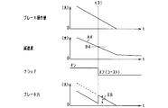
- the flowchart which shows the process sequence of inertial running control. The figure which shows the relationship between the amount of brake operation, and deceleration.
- the figure which shows the deceleration characteristic according to a vehicle speed. The figure which shows the relationship between accelerator operation amount, a vehicle speed, and deceleration.
- (A) is a figure which shows the deceleration characteristic of the vehicle at the time of downhill driving
- (b) is a figure which shows the deceleration characteristic of the vehicle at the time of uphill driving
- the flowchart which shows the process sequence of the inertia running control in 2nd Embodiment.
- release release.
- the flowchart which shows the process sequence of the inertia running control in 5th Embodiment.
- the figure which shows the relationship between the start and cancellation
- the figure which shows the relationship between the amount of brake operation, a vehicle speed, and deceleration.
- the time chart which shows concrete brake control at the time of inertial travel cancellation.
- the time chart which shows concrete brake control at the time of inertial running start.
- an engine 11 is a multi-cylinder internal combustion engine driven by combustion of fuel such as gasoline or light oil, and appropriately includes a fuel injection valve, an ignition device, and the like as is well known.
- the engine 11 is integrally provided with an ISG 13 (Integrated Starter Generator) as a generator, and the rotation shaft of the ISG 13 is connected to the engine output shaft 12 by a belt or the like so as to be driven mutually.
- ISG 13 Integrated Starter Generator
- the rotation shaft of the ISG 13 is rotated by the rotation of the engine output shaft 12, while the engine output shaft 12 is rotated by the rotation of the rotation shaft of the ISG 13.
- the ISG 13 has a power generation function for generating power (regenerative power generation) by rotation of the engine output shaft 12 and a power output function for applying a rotational force to the engine output shaft 12.
- a power generation function for generating power (regenerative power generation) by rotation of the engine output shaft 12
- a power output function for applying a rotational force to the engine output shaft 12.
- the in-vehicle battery 14 is electrically connected to the ISG 13. In this case, the power is supplied from the battery 14 to drive the ISG 13 and the battery 14 is charged by the generated power of the ISG 13. The electric power of the battery 14 is used to drive various electric loads mounted on the vehicle.
- an auxiliary machine 15 such as a water pump or a fuel pump is mounted on the vehicle 10 as a driven device driven by the rotation of the engine output shaft 12.
- an air conditioner compressor may be included as the driven device.
- Driven devices include those directly coupled to the engine output shaft 12 and those coupled to the engine output shaft 12 by a clutch mechanism, in addition to those coupled to the engine 11 by a belt or the like. .
- a transmission 17 is connected to the engine output shaft 12 via a clutch device 16 having a power transmission function.
- the clutch device 16 is, for example, a friction clutch, and includes a disk (flywheel or the like) on the engine 11 side connected to the engine output shaft 12 and a disk (clutch disk) on the transmission 17 side connected to the transmission input shaft 21. Etc.) and a set of clutch mechanisms.
- a power transmission state (clutch connection state) in which power is transmitted between the engine 11 and the transmission 17 is established, and both the disks are separated from each other.
- a power cut-off state (clutch cut-off state) in which power transmission between the engine 11 and the transmission 17 is cut off is established.
- the clutch device 16 of the present embodiment is configured as an automatic clutch that switches between a clutch engaged state / clutch disengaged state by an actuator such as a motor.
- the clutch device 16 may be provided inside the transmission 17.
- the transmission 17 is, for example, a continuously variable transmission (CVT) or a multi-stage transmission having a plurality of shift stages.
- the transmission 17 shifts the motive power of the engine 11 input from the transmission input shaft 21 with a gear ratio corresponding to the vehicle speed and the engine rotation speed, and outputs it to the transmission output shaft 22.
- Wheels 27 are connected to the transmission output shaft 22 via a differential gear 25 and a drive shaft 26 (vehicle drive shaft).
- Each wheel 27 is provided with a brake device 28 that applies a braking force to each wheel 27 by being driven by a hydraulic circuit (not shown) or the like.
- the brake device 28 adjusts the braking force for each wheel 27 in accordance with the pressure of a master cylinder (not shown) that transmits the depression force of the brake pedal to the hydraulic oil.
- the present system includes an engine ECU 31 that controls the operating state of the engine 11 and a transmission ECU 32 that controls the clutch device 16 and the transmission 17 as vehicle-mounted control means.
- These ECUs 31 and 32 are both well-known electronic control devices including a microcomputer and the like, and appropriately control the engine 11 and the transmission 17 based on the detection results of various sensors provided in the system. carry out.
- These ECUs 31 and 32 are communicably connected to each other, and can share control signals, data signals, and the like.
- the ECU 31 is configured to include two ECUs 31 and 32, and the engine ECU 31 constitutes a “vehicle control device”.
- the present invention is not limited thereto, and the vehicle control device may be configured by two or more ECUs. .
- an accelerator sensor 41 that detects an operation amount (accelerator operation amount) of an accelerator pedal as an accelerator operation member
- a brake sensor 42 that detects an operation amount (brake operation amount) of a brake pedal as a brake operation member.
- a vehicle speed sensor 43 for detecting the vehicle speed, an inclination angle sensor 44 for detecting the inclination angle of the traveling road surface of the vehicle 10, a rotation speed sensor 45 for detecting the engine rotation speed, and the like are provided. Detection signals from these sensors are sequentially input to the engine ECU 31.
- the system is provided with a voltage sensor for detecting battery voltage, a load sensor (air flow meter, intake pressure sensor) for detecting engine load, a cooling water temperature sensor, an outside air temperature sensor, an atmospheric pressure sensor, and the like.
- a voltage sensor for detecting battery voltage
- a load sensor air flow meter, intake pressure sensor
- a cooling water temperature sensor for detecting engine load
- a cooling water temperature sensor for detecting engine load
- an outside air temperature sensor for detecting engine load
- an atmospheric pressure sensor and the like. The illustration is omitted.
- the engine ECU 31 performs various engine controls such as fuel injection amount control by a fuel injection valve and ignition control by an ignition device based on detection results of various sensors, engine start by ISG 13, engine torque assist and power generation control, brake device Brake control by 28 is performed. Further, the transmission ECU 32 performs intermittent control of the clutch device 16 and shift control of the transmission 17 based on detection results of various sensors.
- the vehicle 10 has a function of causing the vehicle 10 to coast by inertia with the clutch device 16 disconnected in a situation where the vehicle 10 is traveling by the operation of the engine 11. By carrying out this inertial running, the fuel consumption is improved.
- the engine ECU 31 has a control function related to coasting, and the engine 11 is in an operating state, the clutch device 16 is in a connected state (clutch-on state), and the vehicle 10 is traveling, and the engine 11 is in a stopped state. Then, the clutch device 16 is switched to a coasting state in which the vehicle 10 is coasted with the clutch device 16 in a disconnected state (clutch off state).
- the engine 11 is in an operating state (for example, an idle state) and the clutch device 16 is in the disconnected state in the inertial traveling state. May be. In this case, it is preferable to keep the engine 11 in an operating state in preparation for the next re-acceleration under the clutch-off state, and maintain the engine 11 in the idling state in order to save fuel.
- the engine ECU 31 turns off the clutch device 16 (off state) and sets the vehicle 10 in the inertial travel state in accordance with the establishment of predetermined execution conditions including the accelerator condition and the brake condition.
- Implementation conditions include that the engine speed is stable at a predetermined value or higher (for example, idling speed or higher), that the vehicle speed is within a predetermined range (for example, 20 to 120 km / h), road gradient (inclination). Is within a predetermined range, and the drive amount of the electric load is preferably a predetermined value or less.
- the engine ECU 31 releases the inertial traveling state by setting the clutch device 16 to a connected state (on state) in response to establishment of predetermined release conditions including an accelerator condition and a brake condition. At this time, it is good to cancel the inertial running state as the execution condition of the inertial running is not established.
- deceleration [m / s2] at that time is a value corresponding to the vehicle speed, and for example, exhibits a deceleration characteristic as shown as a clutch-off characteristic XA in FIG.
- This state is a slow deceleration state where there is no engine brake and the vehicle is decelerated mainly by the vehicle running resistance.
- deceleration [m / s2] is shown as negative acceleration [m / s2].
- the deceleration [m / s2] is greater than that during inertial traveling.
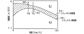
- FIG. As shown in FIG.
- the characteristics shown in FIG. 2 are determined in consideration of the fact that the CVT is used as the transmission 17 and the gear ratio of the CVT is switched according to the vehicle speed.
- the clutch off time characteristic XA corresponds to “clutch off correlation data”
- the clutch on time characteristic XB corresponds to “clutch on correlation data”.
- the area above the characteristic XB is a deceleration region realized by performing fuel injection when the clutch is on. That is, the region above the characteristic XB is a region where the deceleration is reduced by overcoming the engine brake by the combustion torque of the fuel in a state where the vehicle 10 is decelerating. Below the characteristic XB is a deceleration region realized by a brake operation when the clutch is on. Assuming that the clutch is on, the deceleration indicated by the characteristic XA is a deceleration realized by performing fuel injection, that is, a region where the engine braking is overcome by the combustion torque of the fuel and the deceleration is reduced. It corresponds to the deceleration of.
- a vehicle decelerating state in a region where the deceleration is smaller than the characteristic XB, by performing fuel injection, a desired deceleration (characteristic (Deceleration smaller than XB) is obtained.
- a desired deceleration in a region of the characteristics XA to XB, a desired deceleration can be obtained by the driver's braking operation, and fuel injection for realizing the deceleration in the region of the characteristics XA to XB is not performed. Thereby, the fuel consumption can be reduced.
- an actual deceleration rate that is a vehicle deceleration rate caused by the driver's brake operation is calculated, and the actual deceleration rate is determined as accelerator off and It is determined whether or not it is larger than a threshold value (threshold value based on the characteristic XB, corresponding to the first threshold value) determined as the vehicle deceleration rate in the clutch-on state. Then, when it is determined that the actual deceleration rate is larger than the threshold value, the inertial running is canceled, and when it is determined that the actual deceleration rate is smaller than the threshold value, the inertial running is maintained.
- a threshold value threshold value based on the characteristic XB, corresponding to the first threshold value
- the accelerator operation amount decreases from a state where the vehicle 10 is normally running with the accelerator on and the clutch on, the vehicle 10 is in an accelerated or constant speed state during the decrease (until the accelerator is turned off). Transition to deceleration state.
- the accelerator operation amount has an operation amount range that causes acceleration or constant speed according to the vehicle speed, and an operation amount range that causes deceleration.
- the accelerator operation amount decreases, the accelerator operation amount reaches the boundary threshold value of both ranges. At that time, the vehicle 10 shifts from the acceleration or constant velocity state to the deceleration state.
- an actual deceleration ratio that is a deceleration ratio of the vehicle caused by a decrease in the driver's accelerator operation amount is calculated. Then, it is determined whether or not it is larger than a threshold value (threshold value based on the characteristic XA, corresponding to the second threshold value) determined as the total deceleration of the vehicle when the accelerator is off and the clutch is off. In addition, coasting is started when it is determined that the actual deceleration rate is greater than the threshold value, and non-inertial travel is maintained when it is determined that the actual deceleration rate is less than the threshold value.
- a threshold value threshold value based on the characteristic XA, corresponding to the second threshold value
- the actual deceleration [m / s2] which is the actual deceleration of the vehicle, is used as the “actual deceleration rate”, and the deceleration threshold [m / s2] is used as the “threshold”.
- the deceleration used here is an absolute value of acceleration, and a large deceleration means a large degree of deceleration.
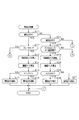
- FIG. 3 is a flowchart showing a processing procedure of inertial running control, and this processing is repeatedly performed by the engine ECU 31 at a predetermined cycle.
- step S11 it is determined whether or not the vehicle 10 is currently in an inertia running state with the clutch off. If YES, the process proceeds to step S12, and if NO, the process proceeds to step S21.
- step S12 it is determined whether or not the brake is on. The brake-on state is determined based on the fact that the brake operation amount detected by the brake sensor 42 is greater than zero. If step S12 is YES, the process proceeds to step S13.
- step S13 the actual deceleration A1 [m / s2] of the vehicle that occurs in response to the driver's brake operation is calculated.
- the actual deceleration A1 is calculated using the relationship of FIG. In FIG. 4, the relationship between the brake operation amount and the deceleration is determined, and the actual deceleration A1 is calculated based on the brake operation amount (the brake pedal depression amount) detected by the brake sensor 42. In this case, a larger value is calculated as the actual deceleration A1 as the brake operation amount is larger.
- a threshold value B1 [m / s2] determined as the deceleration of the vehicle in the accelerator-off and clutch-on state (non-coast deceleration state) is calculated.
- the threshold value B1 is calculated using the correlation data shown in FIG. FIG. 5 shows the same characteristics XA and XB as FIG. 2, and the vertical axis is “deceleration” for convenience.
- the clutch-on-time characteristic XB in FIG. 5 corresponds to correlation data indicating the correlation between the vehicle deceleration in the accelerator-off and clutch-on state and the vehicle speed, and based on the current vehicle speed using this correlation data.
- a threshold value B1 is calculated.
- the threshold value B1 is calculated as a value having a larger deceleration than a threshold value B2 described later.
- step S15 it is determined whether or not the actual deceleration A1 is greater than or equal to the threshold value B1. If A1 ⁇ B1, the process proceeds to step S16, and if A1 ⁇ B1, the process proceeds to step S17. In step S16, it is determined to shift to the clutch-on state, that is, to release the inertia running state. In step S17, it is determined to maintain the clutch-off state, that is, to maintain the coasting state.
- step S21 it is determined whether or not the vehicle 10 is currently in a normal driving state with the clutch on. If YES, the process proceeds to step S22.
- step S22 it is determined whether or not the accelerator is on and the vehicle is in a decelerating state. Whether or not the accelerator is on is determined based on the fact that the accelerator operation amount detected by the accelerator sensor 41 is greater than zero. Whether or not the vehicle is in a deceleration state is determined based on the fact that the vehicle speed detected by the vehicle speed sensor 43 is decreasing. If step S22 is YES, the process proceeds to step S23.
- step S23 the actual deceleration A2 [m / s2] of the vehicle that occurs with a decrease in the accelerator operation amount of the driver is calculated.
- the actual deceleration A2 is calculated using the relationship of FIG. In FIG. 6, the relationship between the accelerator operation amount, the vehicle speed, and the deceleration is determined, and the actual deceleration A2 is calculated based on the accelerator operation amount (accelerator pedal depression amount) detected by the accelerator sensor 41 and the vehicle speed. In this case, a larger value is calculated as the actual deceleration A2 as the accelerator operation amount is smaller or the vehicle speed is larger.
- a threshold value B2 [m / s2] determined as the deceleration of the vehicle in the accelerator-off and clutch-off state (coast deceleration state) is calculated.
- the threshold B2 is calculated using the correlation data shown in FIG.
- the clutch-off characteristic XA in FIG. 5 corresponds to correlation data indicating the correlation between the vehicle deceleration in the accelerator-off and clutch-off states and the vehicle speed, and based on the current vehicle speed using this correlation data.
- a threshold value B2 is calculated.
- step S25 it is determined whether or not the actual deceleration A2 is greater than or equal to the threshold B2. If A2 ⁇ B2, the process proceeds to step S26, and if A2 ⁇ B2, the process proceeds to step S27.
- step S26 it is determined to shift to the clutch-off state, that is, shift to the inertial running state. Further, it is determined to stop the operation of the engine 11 in accordance with the transition to the inertia running state. Alternatively, the engine 11 is shifted to the idle operation state.
- step S27 it is determined to maintain the clutch-on state, that is, to maintain the normal running state.
- the deceleration state of the vehicle 10 becomes “actual deceleration A1 ⁇ threshold B1”.
- the vehicle 10 is decelerated by the braking force according to the brake operation amount.
- the vehicle 10 is decelerated by rotating the engine output shaft on the axle side (so-called engine braking) in addition to the braking force according to the brake operation amount.
- engine braking engine braking
- the brake device at the beginning of the inertial travel cancellation. 28 is intended to limit the braking force. More specifically, when it is determined in step S15 of FIG. 3 that A1 ⁇ B1 and inertial running is released, the engine ECU 31 performs a brake control process shown in FIG.
- step S31 the amount of engine brake generated in the vehicle 10 at the time of releasing inertia running, that is, the time of shifting from clutch-off to clutch-on is estimated.
- the engine brake amount is estimated based on the driving state of the driven device that is drivingly connected to the engine output shaft 12.
- the engine brake amount is estimated based on the driving state of the ISG 13 and the auxiliary machine 15. Further, the engine brake amount may be estimated in consideration of the engine speed after the clutch is turned on, the engine water temperature, and the like.
- step S32 it is determined whether or not the engine brake amount EB is equal to or greater than a predetermined value. If YES, the process proceeds to step S33.
- step S33 the brake force applied by the brake device 28 is limited. At this time, the command brake force is calculated by subtracting the brake force corresponding to the engine brake amount from the basic brake force calculated based on the brake operation amount of the driver. Then, the braking force is applied by the brake device 28 based on the command braking force. Note that step S32 may be omitted.
- FIG. 8 is a time chart showing the brake control of FIG. 7 more specifically.
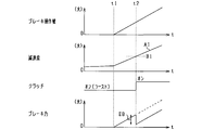
- the brake operation of the driver is started at the timing t1 while the vehicle 10 is coasting, and the deceleration (negative acceleration) of the vehicle 10 gradually increases as the brake operation amount (pedal depression amount) increases.
- the brake operation amount pedal depression amount
- the transition from clutch-off to clutch-on is performed.
- the vehicle 10 is decelerated by the braking force corresponding to the brake operation amount before the timing t2, while the vehicle 10 is decelerated by the engine brake in addition to the braking force after the timing t2.
- the engine brake amount EB is calculated, and the brake force of the brake device 28 is subtracted by an amount corresponding to EB. After timing t2, the braking force of the brake device 28 gradually increases.
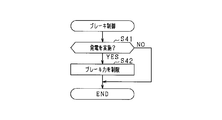
- step S41 it is determined whether or not power generation by the ISG 13 is performed immediately after switching to clutch-on. And if it determines with implementing electric power generation, it will progress to step S42 and the restriction
- a configuration in which the braking force by the brake device 28 is not applied in a period until a predetermined time elapses after the clutch is turned on in other words, a configuration in which the start of applying the braking force is delayed.
- FIG. 10 is a time chart showing the brake control of FIG. 9 more specifically.
- the driver's braking operation is started at timing t11 while the vehicle 10 is coasting, and the transition from clutch-off to clutch-on is performed at timing t12 when the actual deceleration A1 is greater than the threshold value B1.
- the application of the braking force by the brake device 28 is stopped during the period TA in the figure, and the application of the braking force is started after the passage of TA.
- the configuration may be such that brake control is performed when inertial running is started from the normal running state.
- the deceleration state of the vehicle 10 becomes “actual deceleration A2 ⁇ threshold B2”.
- the vehicle 10 is decelerated by rotating the engine output shaft 12 on the axle side (so-called engine brake).
- engine brake when “actual deceleration A2 ⁇ threshold value B2” is established and the clutch is turned off, the vehicle 10 is decelerated while the braking force for the engine brake is lost. In this case, there is a concern that the deceleration suddenly changes before and after the start of inertial running.
- the engine ECU 31 determines that the actual deceleration A2 is greater than the threshold value B2 during the non-inertial travel, and starts the inertia travel when the inertia travel is started (when step S25 in FIG. 3 is YES).
- the braking force by the brake device 28 is generated regardless of the brake operation by the driver at the beginning of the operation.
- the engine ECU 31 calculates the engine brake amount according to the driving state of the driven devices such as the ISG 13 and the auxiliary machine 15, and adjusts the braking force by the brake device 28 based on the engine brake amount. It is also possible to adjust the braking force of the brake device 28 based on the vehicle speed, taking into account that the deceleration differs according to the vehicle speed.
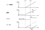
- FIG. 11 is a time chart specifically showing brake control at the start of inertial running.
- the vehicle 10 is decelerated when the driver's accelerator operation is loosened at timing t21 during non-inertial travel of the vehicle 10, and the vehicle 10 is decelerating (decreasing the accelerator operation amount (pedal depression amount)). (Negative acceleration) gradually increases. Then, at the timing t22 when the actual deceleration A2 becomes larger than the threshold value B2, the shift from the clutch on to the clutch off is performed. At this time, the vehicle 10 is decelerated by the engine brake before the timing t22, whereas the vehicle 10 is decelerated after the timing t22 with no engine brake. After the timing t22, the braking force is applied by the brake device 28 to supplement the braking force for the engine brake. Note that the braking force application by the brake device 28 may be performed only for a predetermined period from the timing t22.
- the actual deceleration A1 of the vehicle 10 is compared with a threshold value B1 defined as the deceleration of the vehicle 10 in the accelerator off and clutch on state.
- a threshold value B1 defined as the deceleration of the vehicle 10 in the accelerator off and clutch on state.
- inertial running is canceled.
- the actual deceleration A1 is smaller than the threshold value B1
- coasting is maintained. In this case, it is possible to suppress the frequent occurrence of coasting on / off (switching), and it is possible to expect an improvement in fuel efficiency improvement and an improvement in drivability. As a result, appropriate inertial running control can be realized.
- inertial traveling is canceled on condition that the actual deceleration A1 of the vehicle 10 increases and reaches the threshold value B1 on the characteristic XB. Therefore, fuel injection is required when canceling inertial traveling.
- the desired deceleration can be obtained without any problem, and the fuel consumption can be reduced.
- the vehicle deceleration rate when the accelerator is off and the clutch is on (non-coast deceleration state) varies depending on the vehicle speed. Considering this point, more appropriate inertial traveling control can be realized by calculating the threshold value B1 based on the vehicle speed.
- the braking force by the brake device 28 is limited at the beginning of the inertial traveling cancellation. A sudden change in deceleration at the time of release is suppressed, and as a result, deterioration of drivability can be suppressed.
- the degree of restriction of the braking force by the braking device 28 is adjusted based on the power generation state of the ISG 13 (driving state of the driven device). In this case, it is possible to suppress the generation of excessive braking force on the vehicle 10 due to the regenerative braking force generated by the regenerative power generation while performing the regenerative power generation from the cancellation of inertial running in the vehicle deceleration state. That is, a sudden change in the braking force in the vehicle 10 can be suppressed, and as a result, drivability can be improved.
- the actual deceleration A2 of the vehicle 10 is compared with the threshold value B2 defined as the deceleration of the vehicle 10 in the accelerator-off and clutch-off state in the deceleration state during non-inertial travel (clutch on).
- the threshold value B2 defined as the deceleration of the vehicle 10 in the accelerator-off and clutch-off state in the deceleration state during non-inertial travel (clutch on).
- inertial running is started.
- the threshold value B2 defined as the deceleration of the vehicle 10 in the accelerator-off and clutch-off state in the deceleration state during non-inertial travel (clutch on).
- inertial running is started.
- the threshold value B2 when shifting to the clutch-off state for coasting, an actual deceleration corresponding to the clutch-off state occurs, and the deceleration behavior of the vehicle 10 according to the driver's deceleration request is obtained.
- the actual deceleration A2 is smaller than the threshold value B2, non-iner
- inertial travel is started on the condition that the actual deceleration A2 of the vehicle 10 increases and reaches the threshold value B2 on the characteristic XA. Therefore, fuel injection is required at the start of the inertial travel. Thus, the desired deceleration can be obtained without reducing the fuel consumption.
- the vehicle deceleration rate in the accelerator-off and clutch-off state (coast deceleration state) varies depending on the vehicle speed. Considering this point, more appropriate inertial traveling control can be realized by calculating the threshold B2 based on the vehicle speed.
- the actual deceleration A2 is calculated based on the driver's accelerator operation amount when the vehicle 10 decelerates due to a decrease in the accelerator operation amount during non-inertial travel, it is appropriate while directly reflecting the driver's deceleration request. Inertia running control can be implemented.
- the braking force by the brake device 28 is applied regardless of the brake operation by the driver at the beginning of the inertial travel. Because of this, sudden change in deceleration at the start of inertial running is suppressed, and consequently deterioration in drivability can be suppressed.
- the brake force by the brake device 28 is adjusted based on the driving state of the driven devices such as the ISG 13 and the auxiliary machine 15.
- the engine brake amount differs depending on the drive state of the driven device, it is possible to perform the brake control in consideration of the engine brake amount immediately before the coasting is started. Thereby, the sudden change of the deceleration state in the vehicle 10 can be suppressed, and the improvement of drivability can be aimed at by extension.
- the characteristics XA and XB used for obtaining the threshold values B1 and B2 are defined according to the gear ratio of the transmission 17, a desired inertial traveling control can be realized in consideration of a deceleration state depending on the gear ratio.
- the clutch device 16 is used for each of the case where inertial traveling is canceled during inertial traveling (when switching from clutch off to on) and when inertial traveling is started during normal traveling (when switching from clutch on to off).
- the release and start of inertial running are appropriately controlled. Accordingly, it is possible to appropriately control the release and start timing of inertial travel and the frequency of inertial travel.
- the threshold value B1 of deceleration when releasing inertial traveling is set to a value larger than the threshold value B2 of deceleration when starting inertial traveling, that is, the value of deceleration is large, at the time of releasing and starting inertial traveling, Appropriate inertial running control can be performed while reflecting the clutch off-time characteristic XA and the clutch-on time characteristic XB in the vehicle 10.
- an influence parameter that affects the vehicle deceleration in the accelerator-off state is acquired, and at least one of the actual deceleration and the threshold value during inertial driving is corrected based on the influence parameter.
- the vehicle 10 also corrects at least one of the actual deceleration and the threshold value during non-inertial traveling based on the influence parameter.
- the deceleration rate when the accelerator is off in the vehicle 10 becomes small.
- the deceleration characteristics of the vehicle 10 are affected, and as shown in FIG. 12A, the deceleration characteristics change from basic characteristics XA and XB indicated by solid lines to characteristics XA1 and XB1 indicated by broken lines. .
- the deceleration rate when the accelerator is off in the vehicle 10 increases.
- the deceleration characteristics of the vehicle 10 are also affected, and as shown in FIG. 12B, the deceleration characteristics are changed from the basic characteristics XA and XB indicated by the solid lines to the characteristics XA2 and XB2 indicated by the alternate long and short dash lines. Change.
- the downward slope corresponds to a factor that decreases the deceleration of the vehicle 10
- the upward slope corresponds to a factor that increases the deceleration of the vehicle 10.
- the actual decelerations A1, A2 and the threshold values B1, B2 are corrected in consideration of the change in the deceleration characteristic in this way, and the actual decelerations A1, A2 and threshold values B1, B2 after the correction are used, The size comparison is performed.
- the influence parameter corresponds to at least one of the state of the vehicle and the driving environment. Specifically, (1) road inclination, (2) road surface condition, (3) driving resistance, (4) number of passengers / It is possible to use parameters such as loading weight and (5) change over time. Among these, the road inclination of (1) can be detected by the inclination angle sensor 44. Each of (2) to (5) can be directly detected by a sensor or the like, but in addition to acquiring information by sensor detection, it is possible to acquire information in a predetermined stable running state. . For example, when the vehicle is traveling on a flat road with the accelerator off and the brake off and no gradient, information is acquired by comparison with a reference value.
- each of the above parameters affects the vehicle deceleration (in other words, increase / decrease in vehicle deceleration), and the value of each parameter corresponds to a value that reduces the deceleration as in downhill driving. If so, the actual decelerations A1 and A2 and the threshold values B1 and B2 are calculated using the characteristics XA1 and XB1 (characteristics whose deceleration is smaller than the basic characteristics XA and XB) shown in FIG. Further, if the value of each parameter corresponds to a value that increases the deceleration as in uphill running, the characteristics XA2 and XB2 shown in FIG. 12B (the deceleration is lower than the basic characteristics XA and XB). Actual decelerations A1 and A2 and threshold values B1 and B2 are calculated using a large characteristic). The actual deceleration and the threshold value are corrected by such arithmetic processing.
- FIG. 13 is a flowchart showing a processing procedure of inertial running control, and this processing is repeatedly performed at a predetermined cycle by the engine ECU 31 in place of FIG. 3 described above.
- the same steps as those in FIG. The changes from the processing of FIG. 3 are the addition of steps S51 and S52 and the change of the processing contents of steps S13, S14, S23, and S24.
- step S51 the first parameter is acquired as the influence parameter.
- the first parameter is at least one of the above (1) to (5).
- step S13 the actual deceleration A1 [m / s2] of the vehicle caused by the driver's braking operation is calculated, and in the subsequent step S14, the threshold value B1 [m / s2] is calculated.
- the actual deceleration A1 and the threshold value B1 are calculated in consideration of the change in the deceleration characteristics as shown in FIGS. 12A and 12B according to the first parameter.
- step S52 the second parameter is acquired as the influence parameter.
- the second parameter is at least one of the above (1) to (5).
- the first parameter and the second parameter may be integrated to be a common parameter.
- step S23 the actual deceleration A2 [m / s2] of the vehicle that occurs as the driver's accelerator operation amount decreases is calculated, and in step S24, the threshold B2 [m / s2] is calculated. At this time, the actual deceleration A2 and the threshold B2 are calculated considering that the deceleration characteristics change as shown in FIGS.
- the region between the characteristic XB is an inertial traveling region in which the vehicle 10 performs inertial traveling, and inertial traveling is started when the deceleration rate of the vehicle 10 changes from outside the inertial traveling region (Y2, Y4). )
- the inertia running is canceled (Y1, Y3). Note that “Y1, Y2” corresponds to the state transition described in the first embodiment.
- symbol ACC is an accelerator pedal
- symbol BR is a brake pedal
- Y1 is a case where the amount of brake operation increases in a vehicle deceleration state during inertial traveling.
- inertial traveling is accompanied by a state transition from a region where the deceleration is smaller than a region where the deceleration is smaller than the clutch-on characteristic XB. Is released.
- Y2 is a case where the accelerator operation amount decreases in the vehicle deceleration state in the non-inertial traveling, and in such a case, along with the state transition from the region where the deceleration is smaller than the clutch-off characteristic XA, the inertia Traveling starts.
- Y3 is a case where the accelerator operation amount increases in a vehicle deceleration state in inertial traveling.
- inertial traveling is accompanied by a state transition from a region where the deceleration is larger than a region where the deceleration is smaller than the clutch-off characteristic XA. Is released.
- Y4 is a case where the brake operation amount decreases in the vehicle deceleration state in the non-inertial traveling.
- the inertia is accompanied by the state transition from the region where the deceleration is larger than the region when the clutch-on characteristic XB is larger to the smaller region. Traveling starts.
- FIGS. 16 and 17 are flowcharts showing a process procedure of inertial running control, and this process is repeatedly performed by the engine ECU 31 at a predetermined cycle.
- steps S11 to S17 and steps S21 to S27 are the same as those in FIG. 3 described above, and will not be described in detail.
- the difference from FIG. 3 is that when the vehicle is coasting and the brake is not on (when S11 is YES and S12 is NO), the process shifts to another process, and the vehicle is traveling normally and the accelerator is on.
- S11 is YES and S12 is NO
- step S61 it is determined whether or not the accelerator is on and the vehicle is in a decelerating state. This determination is performed based on the detection result of the accelerator sensor 41 and the detection result of the vehicle speed sensor 43, as in step S22. If step S61 is YES, the process proceeds to step S62.
- step S62 the actual deceleration A3 [m / s2] of the vehicle occurring when the accelerator operation amount of the driver is increased is calculated.
- the actual deceleration A3 is calculated using the relationship shown in FIG. In FIG. 18, the relationship between the accelerator operation amount, the vehicle speed, and the deceleration is determined, and the actual deceleration A3 is calculated based on the accelerator operation amount (accelerator pedal depression amount) detected by the accelerator sensor 41 and the vehicle speed. In this case, the smaller the accelerator operation amount or the smaller the vehicle speed, the smaller the actual deceleration A3 is calculated.
- the relationship in FIG. 18 is the same as the relationship shown in FIG. 6 for obtaining the actual deceleration A2. However, the relationship in FIG. 18 may be different from the relationship in FIG. 6. For example, when comparing with the same accelerator operation amount and vehicle speed, the actual deceleration A3 is made larger or smaller than the actual deceleration A2. Is possible.
- a threshold value B3 [m / s2] determined as the deceleration of the vehicle in the accelerator-off and clutch-off state (coast deceleration state) is calculated.
- the threshold value B3 is calculated based on the vehicle speed using the correlation data shown in FIG.
- step S64 it is determined whether or not the actual deceleration A3 is equal to or less than the threshold value B3. If A3 ⁇ B3, the process proceeds to step S65, and if A3> B3, the process proceeds to step S66.
- step S65 it is determined to shift to the clutch-on state, that is, to release the inertia running state. At this time, by starting the operation of the engine 11 (fuel injection), it is possible to achieve a deceleration rate in a deceleration range that is looser than the clutch-off characteristic XA, that is, a deceleration rate that cannot be obtained in the inertial running state. It has become.
- the process of step S65 corresponds to the above “Y3”.
- step S66 it is determined to maintain the clutch-off state, that is, to maintain the coasting state.
- step S71 it is determined whether or not the brake is on. This determination is performed based on the detection result of the brake sensor 42 as in step S12. If step S71 is YES, the process proceeds to step S72.
- step S72 the actual deceleration A4 [m / s2] of the vehicle that is caused by the driver's brake operation is calculated.
- the actual deceleration A4 is calculated using the relationship of FIG. In FIG. 20, the relationship between the brake operation amount and the deceleration is determined, and the actual deceleration A4 is calculated based on the brake operation amount (the brake pedal depression amount) detected by the brake sensor 42. In this case, a smaller value is calculated as the actual deceleration A4 as the brake operation amount is smaller.
- the relationship of FIG. 20 is the same as the relationship of FIG. 4 for obtaining the actual deceleration A1.
- the relationship of FIG. 20 may be different from the relationship of FIG. 4.
- the actual deceleration A4 can be made larger or smaller than the actual deceleration A1. It is.
- a threshold value B4 [m / s2] determined as the deceleration of the vehicle in the accelerator-off and clutch-on state (non-coast deceleration state) is calculated. Specifically, the threshold value B4 is calculated based on the vehicle speed using the correlation data shown in FIG.
- step S74 it is determined whether or not the actual deceleration A4 is equal to or less than the threshold value B4. If A4 ⁇ B4, the process proceeds to step S75, and if A4> B4, the process proceeds to step S76.
- step S75 it is determined to shift to the clutch-off state, that is, to shift to the inertial running state. Further, it is determined to stop the operation of the engine 11 in accordance with the transition to the inertia running state. Alternatively, the engine 11 is shifted to the idle operation state.
- the process in step S75 corresponds to the above “Y4”.
- step S76 it is determined to maintain the clutch-on state, that is, to maintain the normal running state.
- brake assist is performed by the brake device 28 while taking into account the stop of the engine brake.
- step S81 the engine brake amount of the vehicle 10 that is lost with the start of inertial running is estimated.
- the engine brake amount is estimated based on the driving state of the driven device that is drivingly connected to the engine output shaft 12.
- the engine brake amount is estimated based on the driving state of the ISG 13 and the auxiliary machine 15. Further, the engine brake amount may be estimated in consideration of the engine rotation speed before clutch-off, the engine water temperature, and the like.
- step S82 it is determined whether or not the engine brake amount EB is equal to or greater than a predetermined value. If YES, the process proceeds to step S83.
- step S83 the brake device 28 additionally applies a braking force to perform brake assist. At this time, the command brake force is calculated by adding the brake force corresponding to the engine brake amount to the basic brake force calculated based on the brake operation amount of the driver. Then, the braking force is applied by the brake device 28 based on the command braking force. Note that step S82 can be omitted.
- FIG. 22 is a time chart showing the brake control of FIG. 21 more specifically.
- the brake operation by the driver is performed during the normal traveling of the vehicle 10 in the clutch-on state before the timing t31, and the basic braking force corresponding to the brake operation amount (pedal depression amount) is applied to the vehicle 10. And deceleration according to the engine braking force. Further, the amount of brake operation by the driver is reduced with the passage of time, and the deceleration (negative acceleration) of the vehicle 10 is gradually reduced accordingly.
- step S91 it is determined whether or not power generation by the ISG 13 is performed before the start of coasting. If it is determined that power generation is being performed, the process proceeds to step S92, where the brake device 28 additionally applies a brake force to perform brake assist. At this time, it is preferable to brake assist the sum of the engine brake and the power generation brake (power generation load).
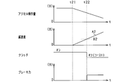
- FIG. 24 is a time chart showing the brake control of FIG. 23 more specifically.
- a brake operation by the driver is performed during normal traveling of the vehicle 10 in the clutch-on state, and the vehicle 10 has a basic braking force corresponding to a brake operation amount (a pedal depression amount) and The engine braking force and the braking force corresponding to the power generation load of the ISG 13 are generated.
- the amount of brake operation by the driver is reduced with the passage of time, and the deceleration (negative acceleration) of the vehicle 10 gradually decreases accordingly.
- the shift from the clutch on to the clutch off is performed.
- the braking force between the engine brake and the power generation load is lost as the clutch is turned off.
- the brake force for the lost amount is additionally applied by the brake device 28, the change (abrupt change) in the deceleration rate of the vehicle 10 before and after the timing t41 is suppressed.
- inertial running is started or canceled with the decrease or increase of the brake operation amount (in the case of “Y1, Y4”)
- the inertial running is started or canceled with the decrease or increase of the accelerator operation amount In the case of “Y2, Y3”, brake control or torque assist control may be performed.
- the engine ECU 31 estimates the engine brake amount according to the vehicle speed at the end of inertial traveling, the gear ratio of the transmission 17, the engine rotation speed, and the like, and calculates the torque assist amount by the ISG 13 based on the engine brake amount. adjust.
- FIG. 25 is a time chart specifically showing torque control at the end of inertial running.
- the deceleration (negative acceleration) of the vehicle 10 gradually decreases as the accelerator operation amount (pedal depression amount) by the driver increases in the vehicle deceleration state during inertial running.
- the transition from clutch-off to clutch-on is performed.
- engine brake is not generated before timing t51, whereas engine brake is generated at timing t51.
- torque assist by the ISG 13 is performed in order to cancel out the deceleration caused by the engine brake.
- torque assist by the ISG 13 may be performed only for a predetermined period from the timing t51. Further, it is preferable that the torque assist amount is gradually reduced as time elapses.
- the actual deceleration A3 of the vehicle 10 is compared with a threshold B3 defined as the deceleration of the vehicle 10 in the accelerator-off and clutch-off state. If it is smaller than the threshold value B3, inertial running is canceled (corresponding to Y3 in FIG. 14). In this case, when shifting to the clutch-on state in order to cancel inertial running, an actual deceleration corresponding to the clutch-on state occurs, and the deceleration behavior of the vehicle 10 according to the driver's deceleration request is obtained. Further, when the actual deceleration A3 is smaller than the threshold value B3, inertial running is maintained. In this case, it is possible to suppress the frequent occurrence of coasting on / off (switching), and it is possible to expect an improvement in fuel efficiency improvement and an improvement in drivability. As a result, appropriate inertial running control can be realized.
- inertial traveling is released on condition that the actual deceleration A3 of the vehicle 10 decreases and reaches the threshold value B3 on the characteristic XA. This makes it possible to achieve a deceleration rate with no deceleration area. As a result, a desired deceleration rate can be realized.
- the vehicle deceleration rate in the accelerator-off and clutch-off state (coast deceleration state) varies depending on the vehicle speed. Considering this point, more appropriate inertial traveling control can be realized by calculating the threshold value B3 based on the vehicle speed.
- the actual deceleration A4 of the vehicle 10 is compared with the threshold value B4 defined as the deceleration of the vehicle 10 in the accelerator-off and clutch-on state in the deceleration state during non-inertial travel (clutch-on).
- the threshold value B4 defined as the deceleration of the vehicle 10 in the accelerator-off and clutch-on state in the deceleration state during non-inertial travel (clutch-on).
- inertial running is started (corresponding to Y4 in FIG. 14).
- the actual deceleration A4 is larger than the threshold value B4, non-inertial running is maintained. In this case, it is possible to suppress frequent on / off (switching) of inertial running, and an improvement in fuel efficiency improvement and an improvement in drivability can be expected. As a result, it is possible to achieve appropriate inertial running control.
- inertial travel is started on the condition that the actual deceleration A4 of the vehicle 10 becomes smaller and reaches the threshold value B4 on the characteristic XB.
- the desired deceleration can be realized by the braking force based on the brake operation amount.
- the vehicle deceleration rate in the accelerator-off and clutch-on state (coast deceleration state) varies depending on the vehicle speed. Considering this point, more appropriate inertial traveling control can be realized by calculating the threshold value B4 based on the vehicle speed.
- the braking force by the brake device 28 is changed to the brake operation amount by the driver at the beginning of the inertial travel. It was made to increase rather than the braking force based. Therefore, a sudden change in deceleration at the start of inertial running is suppressed, and as a result, deterioration in drivability can be suppressed.
- the brake force by the brake device 28 is adjusted in the initial period based on the driving state of the driven devices such as the ISG 13 and the auxiliary machine 15 (power generation state of the ISG 13 and the like).
- the engine brake amount differs depending on the drive state of the driven device, it is possible to perform the brake control in consideration of the engine brake amount immediately before the coasting is started. Thereby, the sudden change of the deceleration state in the vehicle 10 can be suppressed, and the improvement of drivability can be aimed at by extension.
- the characteristics XA and XB used for obtaining the threshold values B3 and B4 are defined according to the gear ratio of the transmission 17, a desired inertial traveling control can be realized in consideration of the deceleration state depending on the gear ratio.
- the clutch device 16 is used for each of the case where inertial traveling is canceled during inertial traveling (when switching from clutch off to on) and when inertial traveling is started during normal traveling (when switching from clutch on to off).
- the release and start of inertial running are appropriately controlled. Accordingly, it is possible to appropriately control the release and start timing of inertial travel and the frequency of inertial travel.
- the deceleration threshold B3 when canceling inertial traveling is set to a value smaller than the deceleration threshold B4 when inertial traveling is started, that is, the value of the deceleration is small, at the time of canceling and starting inertial traveling, Appropriate inertial running control can be performed while reflecting the clutch off-time characteristic XA and the clutch-on time characteristic XB in the vehicle 10.
- the influence parameter corresponds to at least one of the state of the vehicle and the traveling environment. Specifically, (1) road inclination, (2) road surface state, (3) traveling resistance, (4 It is possible to use parameters such as :) number of passengers / loading weight, and (5) change over time.
- Each of the above parameters affects the vehicle deceleration. If the value of each parameter corresponds to a value that reduces the deceleration as in downhill running, characteristics XA1, XB1 (characteristics in which the deceleration is smaller than the basic characteristics XA, XB) shown in FIG. ) To calculate actual decelerations A3 and A4 and threshold values B3 and B4. Further, if the value of each parameter corresponds to a value that increases the deceleration as in uphill running, the characteristics XA2 and XB2 shown in FIG. 12B (the deceleration is lower than the basic characteristics XA and XB). Actual decelerations A3 and A4 and threshold values B3 and B4 are calculated using a large characteristic). The actual deceleration and the threshold value are corrected by such arithmetic processing.
- FIG. 26 is a flowchart showing a processing procedure of inertial running control, and this processing is an alternative to the above-described FIG. 17 and is repeatedly performed by the engine ECU 31 at a predetermined cycle.
- the same steps as those in FIG. Changes from the processing in FIG. 17 are addition of steps S101 and S102 and changes in the processing contents of steps S62, S63, S72, and S73.
- step S101 when the vehicle 10 is in the inertial running state and is in the accelerator-on deceleration state (when step S61 is YES), the process proceeds to step S101.
- step S101 at least one of the above (1) to (5) is acquired as an influence parameter.
- step S62 the actual deceleration A3 [m / s2] of the vehicle that occurs as the driver's accelerator operation amount increases is calculated, and in step S63, the threshold B3 [m / s2] is calculated.
- the actual deceleration A3 and the threshold B3 are calculated considering that the deceleration characteristics change as shown in FIGS. 12A and 12B according to the influence parameter. It is also possible to add an influence parameter (perform correction) for one of the actual deceleration A3 and the threshold B3. Thereafter, based on the actual deceleration A3 and the threshold value B3, it is determined to cancel or maintain the inertia running (steps S64 to S66).
- step S102 at least one of the above (1) to (5) is acquired as the influence parameter.
- step S72 the actual deceleration A4 [m / s2] of the vehicle caused by the driver's braking operation is calculated, and in the subsequent step S73, the threshold value B4 [m / s2] is calculated.
- the actual deceleration A4 and the threshold B4 are calculated considering that the deceleration characteristics change as shown in FIGS. 12A and 12B according to the influence parameter.
- the deviation amount of the deceleration from the basic characteristics XA and XB is calculated, and the actual decelerations A3 and A4 and the threshold values B3 and B4 are corrected based on the deviation amount. Also good.
- the amount of brake operation increases rapidly in a state where the deceleration rate is smaller than the clutch-off characteristic XA, and changes from the region R1 where the deceleration rate is smaller than the inertia traveling region to the region R2 where the deceleration rate is larger than the inertia traveling region. Change has occurred. In this case, the deceleration rate changes through the inertial running area. Therefore, in the vehicle deceleration state in the non-inertial state, even if the actual deceleration rate of the vehicle 10 is greater than the threshold value determined based on the clutch-off characteristic XA and enters the inertial traveling region, the normal traveling to the inertial traveling is performed. No state change will occur.
- the accelerator operation amount increases rapidly in a state where the deceleration rate is larger than the clutch-on-time characteristic XB, and the region R2 where the deceleration rate is larger than the inertia traveling region changes to the region R1 where the deceleration rate is smaller than the inertia traveling region. Change has occurred. In this case as well, the deceleration rate changes through the inertial running area. Therefore, in the vehicle deceleration state in the non-inertial state, even if the actual deceleration rate of the vehicle 10 becomes smaller than the threshold value determined based on the clutch-on characteristic XB and enters the inertial traveling region, the normal traveling to the inertial traveling is performed. No state change will occur.
- the engine ECU 31 starts coasting when the deceleration of the vehicle 10 is in the region R1 and the vehicle deceleration enters the coasting travel region due to a decrease in the brake operation amount or the like.
- the deceleration amount of the vehicle 10 is in the region R2
- the vehicle deceleration amount enters the inertia traveling region due to an increase in the accelerator operation amount or the like, the inertia traveling is started.
- FIG. 28 is a flowchart showing a processing procedure of inertial running control, and this processing is repeatedly performed by the engine ECU 31 at a predetermined cycle.
- FIG. 28 only processing corresponding to the state changes of Y5 and Y6 is shown, and processing corresponding to the state changes of Y1 to Y4 is performed separately.
- step S111 it is determined whether or not the vehicle 10 is currently in a normal travel (non-inertial travel) state. If YES, the process proceeds to step S112. In step S112, it is determined whether or not the vehicle deceleration rate is in the deceleration region of R1 in FIG. 27. In step S113, it is determined whether or not the vehicle deceleration rate is in the deceleration region of R2 in FIG. At this time, if step S112 is YES, the process proceeds to step S114, and if step S113 is YES, the process proceeds to step S118.
- step S112 determines that the actual deceleration in the non-inertial running state is in a region (R1) that is smaller than the clutch off-time characteristic XA.
- step S113 determines that the actual deceleration in the non-inertial running state is in a region (R2) that is greater than the clutch-on characteristic XB.
- step S114 it is determined whether or not the deceleration of the vehicle 10 is increased by the driver's brake operation. This may be determined, for example, based on whether or not the brake operation amount has increased. If the deceleration rate increases, the process proceeds to the subsequent step S115. If the deceleration rate does not increase, the process ends.
- step S115 in a state where the vehicle deceleration rate is increased by the driver's brake operation, it is determined whether or not the actual deceleration rate changed by the brake operation is larger than a threshold value B5 determined based on the clutch-on characteristic XB. To do.
- FIG. 27 illustrates the threshold value B5.
- step S115 is affirmed.
- the threshold value B5 may be obtained based on the brake operation amount and the vehicle speed.
- step S115 YES, it will progress to step S116 and will determine that normal driving
- step S118 it is determined whether or not the deceleration of the vehicle 10 is reduced by the driver's accelerator operation. This may be determined, for example, based on whether or not the accelerator operation amount has increased. If the deceleration rate is in a decreasing state, the process proceeds to the subsequent step S119. If the deceleration rate is not in a decreasing state, the process is terminated.
- step S119 in a state where the vehicle deceleration rate is reduced by the driver's accelerator operation, it is determined whether or not the actual deceleration rate changed by the accelerator operation is smaller than a threshold value B6 determined based on the clutch off-time characteristic XA.
- FIG. 27 illustrates the threshold B6, and when it is determined in FIG. 27 that the state transition from the region R2 to the region R1 is made, step S119 is affirmed.
- the threshold value B6 may be obtained based on the accelerator operation amount and the vehicle speed.
- step S119 YES, it will progress to step S120 and will determine that normal driving
- the brake operation by the driver is performed and changes depending on the brake operation in a state where the actual deceleration in the non-inertial traveling state is in the region R1 where the deceleration rate is smaller than the inertia traveling region.
- Non-inertial running is maintained when the actual deceleration rate is greater than the clutch-on threshold (B5).
- the accelerator operation by the driver is performed, and the actual deceleration rate that changes due to the accelerator operation is the clutch.
- Non-inertial running is maintained when it is smaller than the off threshold (B6).
- FIG. 29 is obtained by changing a part of FIG.
- changes in Y1 and Y2 occur with an increase in vehicle deceleration.
- the increase in vehicle deceleration is caused by an increase in the brake operation amount by the driver or a decrease in the accelerator operation amount.
- the changes in Y3 and Y4 are caused by a decrease in the vehicle deceleration, and the decrease in the vehicle deceleration is caused by an increase in the accelerator operation amount by the driver or a decrease in the brake operation amount.
- the inertial traveling is started by increasing the actual deceleration as the amount of brake operation by the driver increases during non-inertial traveling (corresponding to Y2).
- the inertia traveling may be canceled by reducing the actual deceleration with a decrease in the brake operation amount by the driver during inertia traveling (corresponding to Y3).
- the inertial traveling is started by reducing the actual deceleration as the accelerator operation amount by the driver increases during non-inertial traveling (corresponding to Y4).
- the inertia traveling may be canceled by increasing the actual deceleration accompanying the decrease in the accelerator operation amount by the driver during inertia traveling (corresponding to Y1).
- the engine ECU 31 performs inertial running control in order to realize the state changes of Y1 to Y4.
- the inertial running is canceled, and if it is determined that the actual deceleration rate is smaller than the threshold value, the inertial running is maintained (corresponding to Y1).
- (C) During inertial running, when it is determined that the actual deceleration calculated based on the brake operation amount (operation amount when the brake is reduced) is smaller than the threshold calculated based on the clutch-off characteristic XA In addition, the inertial running is canceled and the inertial running is maintained when it is determined that the actual deceleration rate is larger than the threshold value (corresponding to Y3).
- (D) During non-inertial travel, it is determined that the actual deceleration calculated based on the accelerator operation amount (the operation amount when the accelerator increases) is smaller than the threshold calculated based on the clutch-on-time characteristic XB. In this case, coasting is started, and when it is determined that the actual deceleration rate is larger than the threshold, the coasting is maintained (corresponding to Y4).
- the engine ECU 31 determines whether the traveling path of the vehicle 10 is a slope, and further, whether it is a downhill or an uphill. Based on the determination result, the above-described (a) to (d) Processing may be performed.
- FIG. 30 may be configured to use the relationship shown in FIG. 30 when calculating the actual vehicle decelerations A1 and A4 caused by the driver's braking operation.
- the relationship between the brake operation amount, the vehicle speed, and the deceleration is determined. According to this relationship, the greater the brake operation amount or the greater the vehicle speed, the larger the actual decelerations A1 and A4. Calculated. The same applies when the processing based on FIG. 29 is performed.
- the brake assist amount is gradually reduced as time elapses from the start of inertial running.
- the brake assist amount is gradually reduced as time elapses from the start of inertial running.
- the brake assist it is possible to shift the deceleration of the vehicle 10 after the start of inertial running to a situation where the driver's accelerator operation is left without performing brake assist while suppressing deterioration of drivability.
- the influence parameter may include the wind direction. That is, whether the tail wind is blowing or the head wind is blowing in the traveling direction of the vehicle is set as the influence parameter.
- the tailwind corresponds to a factor that decreases the vehicle deceleration
- the headwind corresponds to a factor that increases the vehicle deceleration. It is also possible to include wind speed in the influence parameter.
- the influence parameter may be obtained as follows. That is, the engine ECU 31 uses the reference deceleration amount obtained based on the accelerator operation amount or the brake operation amount and the vehicle speed as an influence parameter for reducing or increasing the vehicle deceleration amount, and the actual deceleration obtained from the actually measured speed information. Get the amount of deviation from the degree.
- the relationship shown in FIG. 33 is defined as a correlation map that defines the reference deceleration rate under the reference travel condition of the vehicle 10.
- the engine ECU 31 acquires a deviation amount ⁇ X between a reference deceleration (for example, P1 in FIG. 33) obtained by each condition on the correlation map and an actually measured vehicle deceleration (for example, P2 in FIG. 33).
- the engine ECU 31 also uses the threshold value B1 (or threshold value B4) calculated using the clutch-on time characteristic XB or the threshold value B2 (or threshold value B3) calculated using the clutch-off time characteristic XA based on the deviation amount ⁇ X. ) Is corrected.
- the actual decelerations A1 to A4 can be corrected based on the deviation amount ⁇ X.
- the actual measured value of the vehicle deceleration may be obtained from the detected value of the acceleration sensor or the differential value of the detected value of the vehicle speed sensor.
- the deviation amount ⁇ X may be obtained when the vehicle 10 is not coasting.
- the start and release of inertial running are appropriately controlled while taking into account the deviation amount ⁇ X of deceleration actually generated in use in the vehicle 10, that is, the amount of deviation from the reference value caused by various conditions in each case. can do.
- the thresholds B1 and B4 are calculated as the deceleration on the clutch-on characteristic XB, and the thresholds B2 and B3 are calculated as the deceleration on the clutch-off characteristic XA.
- the threshold values B1 to B4 may be calculated as values smaller or larger than the characteristics XA and XB. That is, the threshold values B1 and B4 may be determined based on the clutch-on time characteristic XB, and the threshold values B2 and B3 may be determined based on the clutch-off time characteristic XA.
- the clutch-off characteristic XA and the clutch-on characteristic XB are determined in consideration of the shift stage of the multi-stage transmission. Good. For example, a plurality of characteristics XA and XB may be determined for each gear position.
- the actual decelerations A1 and A4 are calculated as the actual deceleration rate in the coasting deceleration state based on the brake operation amount that is the brake pedal depression amount, but this may be changed.
- the actual decelerations A1 and A4 are calculated based on the pressure applied by the driver's brake operation (brake hydraulic pressure of the brake device 28) and the depression speed of the brake pedal. Also good. In this case, what is necessary is just the structure which calculates actual deceleration A1, A4 based on the embodiment of brake operation.
- an embodiment of the accelerator operation may be determined based on a parameter other than the accelerator operation amount that is the accelerator pedal depression amount, and the actual decelerations A2 and A3 may be calculated based on the embodiment.
- the actual decelerations A2 and A3 are calculated based on the elapsed time from the start of the decrease in the accelerator operation amount.
- ⁇ A configuration may be used in which the actual deceleration of the vehicle in the coasting deceleration state is calculated without using the parameters related to the driver's brake operation.
- the actual deceleration rate is calculated based on the change in the vehicle speed while the vehicle is coasting.
- the actual deceleration is calculated from the differential value of the actual vehicle speed detected by the vehicle speed sensor 43, and the actual deceleration is compared with a predetermined threshold value.
- the configuration may be such that the actual deceleration of the vehicle in the non-coast deceleration state is calculated without using the parameter relating to the driver's accelerator operation.
- the actual deceleration rate is calculated based on a decrease change in the vehicle speed during normal traveling of the vehicle.
- the actual deceleration is calculated from the differential value of the actual vehicle speed detected by the vehicle speed sensor 43, and the actual deceleration is compared with a predetermined threshold value.
- calculation processing for canceling inertial driving based on the comparison between the actual deceleration A1 and the threshold value B1, and calculation for canceling inertial driving based on simply performing a brake operation without performing the comparison The structure which switches a process may be sufficient.
- calculation processing for starting inertial travel based on the comparison between the actual deceleration A2 and the threshold value B2, and starting inertial travel based on simply releasing the accelerator operation without performing the comparison It may be configured to switch between arithmetic processing to be performed.
- calculation processing for canceling inertial traveling based on the comparison between the actual deceleration A3 and the threshold B3, and inertial traveling is canceled based on simply performing an accelerator operation without performing the comparison. It may be configured to switch between arithmetic processing. Further, during non-inertial travel, calculation processing for starting inertial travel based on the comparison between the actual deceleration A4 and the threshold value B4, and starting inertial travel based on simply releasing the brake operation without performing the comparison It may be configured to switch between arithmetic processing to be performed.
- the transition from the normal travel to the inertia travel and the transition from the inertia travel to the normal travel are determined.
- this may be changed.
- the actual decelerations A1 and A4 and the threshold values B1 and B1 are replaced with the actual brake operation amount and the operation amount threshold value, and the actual brake operation amount and the operation amount threshold value are compared.
- the actual deceleration A2 and A3 and the thresholds B2 and B3 are replaced with the actual accelerator operation amount and the operation amount threshold, and a comparison is made between the actual accelerator operation amount and the operation amount threshold.
- the control for canceling and starting inertial running is adopted. However, it may be configured to change this and perform only one of the control when the inertia traveling is canceled during the inertia traveling and the control when the inertia traveling is started during the normal traveling. .
Abstract
L'invention concerne un dispositif de commande de véhicule qui désactive un embrayage et place un véhicule dans un état de déplacement en roue libre lorsqu'une condition de mise en œuvre prescrite est établie, et active l'embrayage et annule l'état de déplacement en roue libre lorsqu'une condition d'annulation prescrite est établie pendant un déplacement en roue libre. Le dispositif de commande de véhicule est pourvu de moyens de calcul de degré de décélération, de moyens de détermination et de moyens de commande du déplacement. Les moyens de calcul de degré de décélération calculent un degré de décélération réel qui est le degré de décélération du véhicule dans un état de décélération du véhicule pendant un déplacement en roue libre, les moyens de détermination déterminent si le degré de décélération réel calculée par les moyens de calcul de degré de décélération est supérieur ou non à un seuil fixé sur la base du degré de décélération du véhicule pendant que l'accélérateur est désactivé et l'embrayage est engagé, et les moyens de commande de déplacement annulent le déplacement en roue libre lorsque le degré de décélération réel est déterminé être supérieur au seuil, et maintient le déplacement en roue libre lorsque le degré de décélération réel est déterminé être inférieur au seuil.
Priority Applications (7)
| Application Number | Priority Date | Filing Date | Title |
|---|---|---|---|
| EP19193039.5A EP3591249B1 (fr) | 2015-02-25 | 2016-02-25 | Dispositif de commande de véhicule pour commander le fonctionnement d'inertie d'un véhicule |
| US15/553,960 US10457285B2 (en) | 2015-02-25 | 2016-02-25 | Vehicle control device for controlling inertia operation of vehicle |
| EP20207099.1A EP3798462B1 (fr) | 2015-02-25 | 2016-02-25 | Dispositif de commande de véhicule pour commander le fonctionnement d'inertie d'un véhicule |
| CN201680012147.XA CN107407353B (zh) | 2015-02-25 | 2016-02-25 | 控制车辆的惯性行驶的车辆控制装置 |
| EP16755618.2A EP3263941B1 (fr) | 2015-02-25 | 2016-02-25 | Dispositif de commande de véhicule pour commander un déplacement en roue libre d'un véhicule |
| EP21199348.0A EP3954917B1 (fr) | 2015-02-25 | 2016-02-25 | Dispositif de commande de véhicule pour commander le fonctionnement d'inertie d'un véhicule |
| EP21199347.2A EP3954916B1 (fr) | 2015-02-25 | 2016-02-25 | Dispositif de commande de véhicule pour commander le fonctionnement d'inertie d'un véhicule |
Applications Claiming Priority (4)
| Application Number | Priority Date | Filing Date | Title |
|---|---|---|---|
| JP2015-034999 | 2015-02-25 | ||
| JP2015034999 | 2015-02-25 | ||
| JP2016006267A JP6565699B2 (ja) | 2015-02-25 | 2016-01-15 | 車両制御装置 |
| JP2016-006267 | 2016-01-15 |
Publications (1)
| Publication Number | Publication Date |
|---|---|
| WO2016136874A1 true WO2016136874A1 (fr) | 2016-09-01 |
Family
ID=56789590
Family Applications (1)
| Application Number | Title | Priority Date | Filing Date |
|---|---|---|---|
| PCT/JP2016/055621 WO2016136874A1 (fr) | 2015-02-25 | 2016-02-25 | Dispositif de commande de véhicule pour commander un déplacement en roue libre d'un véhicule |
Country Status (2)
| Country | Link |
|---|---|
| EP (2) | EP3954917B1 (fr) |
| WO (1) | WO2016136874A1 (fr) |
Cited By (4)
| Publication number | Priority date | Publication date | Assignee | Title |
|---|---|---|---|---|
| JP2018091416A (ja) * | 2016-12-05 | 2018-06-14 | トヨタ自動車株式会社 | 車両の制御装置 |
| GB2559546A (en) * | 2017-02-01 | 2018-08-15 | Jaguar Land Rover Ltd | Apparatus, method and computer program for controlling a vehicle |
| CN112660085A (zh) * | 2019-10-16 | 2021-04-16 | 罗伯特·博世有限公司 | 用于运行机动车的方法、设备、机动车 |
| US11897494B2 (en) * | 2017-09-26 | 2024-02-13 | Avl List Gmbh | Method and a device for generating a dynamic speed profile of a motor vehicle |
Citations (3)
| Publication number | Priority date | Publication date | Assignee | Title |
|---|---|---|---|---|
| JP2010209902A (ja) * | 2009-03-12 | 2010-09-24 | Toyota Motor Corp | 車両用制御装置 |
| WO2013014741A1 (fr) * | 2011-07-25 | 2013-01-31 | トヨタ自動車株式会社 | Dispositif de commande de véhicule |
| JP2014136476A (ja) * | 2013-01-16 | 2014-07-28 | Mazda Motor Corp | 車両の惰性走行制御装置 |
Family Cites Families (7)
| Publication number | Priority date | Publication date | Assignee | Title |
|---|---|---|---|---|
| JP4743218B2 (ja) * | 2008-03-03 | 2011-08-10 | 日産自動車株式会社 | ハイブリッド車両のクラッチ制御装置 |
| JP5278134B2 (ja) * | 2009-04-20 | 2013-09-04 | いすゞ自動車株式会社 | 惰行制御装置 |
| DE102010003673A1 (de) | 2010-04-07 | 2011-10-13 | Robert Bosch Gmbh | Verfahren zum Betreiben eines Fahrzeugs |
| WO2012032639A1 (fr) * | 2010-09-09 | 2012-03-15 | トヨタ自動車株式会社 | Unité de commande pour transmission |
| WO2013027288A1 (fr) * | 2011-08-24 | 2013-02-28 | トヨタ自動車株式会社 | Appareil de commande de déplacement de véhicule |
| WO2014068725A1 (fr) * | 2012-10-31 | 2014-05-08 | トヨタ自動車株式会社 | Organe de commande de déplacement de véhicule |
| JP6565699B2 (ja) | 2015-02-25 | 2019-08-28 | 株式会社デンソー | 車両制御装置 |
-
2016
- 2016-02-25 WO PCT/JP2016/055621 patent/WO2016136874A1/fr active Application Filing
- 2016-02-25 EP EP21199348.0A patent/EP3954917B1/fr active Active
- 2016-02-25 EP EP21199347.2A patent/EP3954916B1/fr active Active
Patent Citations (3)
| Publication number | Priority date | Publication date | Assignee | Title |
|---|---|---|---|---|
| JP2010209902A (ja) * | 2009-03-12 | 2010-09-24 | Toyota Motor Corp | 車両用制御装置 |
| WO2013014741A1 (fr) * | 2011-07-25 | 2013-01-31 | トヨタ自動車株式会社 | Dispositif de commande de véhicule |
| JP2014136476A (ja) * | 2013-01-16 | 2014-07-28 | Mazda Motor Corp | 車両の惰性走行制御装置 |
Cited By (8)
| Publication number | Priority date | Publication date | Assignee | Title |
|---|---|---|---|---|
| JP2018091416A (ja) * | 2016-12-05 | 2018-06-14 | トヨタ自動車株式会社 | 車両の制御装置 |
| CN108162969A (zh) * | 2016-12-05 | 2018-06-15 | 丰田自动车株式会社 | 用于车辆的控制器 |
| GB2559546A (en) * | 2017-02-01 | 2018-08-15 | Jaguar Land Rover Ltd | Apparatus, method and computer program for controlling a vehicle |
| GB2559546B (en) * | 2017-02-01 | 2020-06-17 | Jaguar Land Rover Ltd | Apparatus, method and computer program for controlling a vehicle |
| US11247681B2 (en) | 2017-02-01 | 2022-02-15 | Jaguar Land Rover Limited | Apparatus, method and computer program for controlling a vehicle |
| US11926324B2 (en) | 2017-02-01 | 2024-03-12 | Jaguar Land Rover Limited | Apparatus, method and computer program for controlling a vehicle |
| US11897494B2 (en) * | 2017-09-26 | 2024-02-13 | Avl List Gmbh | Method and a device for generating a dynamic speed profile of a motor vehicle |
| CN112660085A (zh) * | 2019-10-16 | 2021-04-16 | 罗伯特·博世有限公司 | 用于运行机动车的方法、设备、机动车 |
Also Published As
| Publication number | Publication date |
|---|---|
| EP3954916B1 (fr) | 2023-05-03 |
| EP3954917A1 (fr) | 2022-02-16 |
| EP3954917B1 (fr) | 2023-05-03 |
| EP3954916A1 (fr) | 2022-02-16 |
Similar Documents
| Publication | Publication Date | Title |
|---|---|---|
| JP6565699B2 (ja) | 車両制御装置 | |
| JP5935886B2 (ja) | 車両の制御装置 | |
| JP5853690B2 (ja) | 車両のエンジン自動停止制御装置 | |
| US9067585B2 (en) | Control device for hybrid vehicle | |
| JP5338351B2 (ja) | ハイブリッド車両の制御装置 | |
| JP6331807B2 (ja) | 車両制御装置 | |
| JP6089504B2 (ja) | 車両の制御装置 | |
| JP6130367B2 (ja) | 車両の制御装置 | |
| JP5488713B2 (ja) | 電動車両の制御装置 | |
| JP2012214181A (ja) | 車両制御システム | |
| WO2016136874A1 (fr) | Dispositif de commande de véhicule pour commander un déplacement en roue libre d'un véhicule | |
| JP7005904B2 (ja) | 走行制御装置、車両および走行制御方法 | |
| JP6696282B2 (ja) | 車両制御装置 | |
| JP6011352B2 (ja) | 車両の惰性走行制御装置 | |
| JP2014091338A (ja) | 車両の走行制御装置 | |
| JP5924242B2 (ja) | アイドルストップ制御装置及びアイドルストップ制御方法 | |
| JP6958082B2 (ja) | 走行制御装置、車両および走行制御方法 | |
| JP6859783B2 (ja) | 走行制御装置、車両および走行制御方法 | |
| JP6828779B2 (ja) | 車両制御装置 | |
| JP5369912B2 (ja) | 車両用自動変速機の制御装置 | |
| JP2019031189A (ja) | 走行制御装置、車両および走行制御方法 | |
| JP2016153681A (ja) | 車両制御装置 |
Legal Events
| Date | Code | Title | Description |
|---|---|---|---|
| 121 | Ep: the epo has been informed by wipo that ep was designated in this application |
Ref document number: 16755618 Country of ref document: EP Kind code of ref document: A1 |
|
| WWE | Wipo information: entry into national phase |
Ref document number: 15553960 Country of ref document: US |
|
| NENP | Non-entry into the national phase |
Ref country code: DE |
|
| REEP | Request for entry into the european phase |
Ref document number: 2016755618 Country of ref document: EP |