WO2013011779A1 - Dispositif de stockage d'électricité - Google Patents
Dispositif de stockage d'électricité Download PDFInfo
- Publication number
- WO2013011779A1 WO2013011779A1 PCT/JP2012/065487 JP2012065487W WO2013011779A1 WO 2013011779 A1 WO2013011779 A1 WO 2013011779A1 JP 2012065487 W JP2012065487 W JP 2012065487W WO 2013011779 A1 WO2013011779 A1 WO 2013011779A1
- Authority
- WO
- WIPO (PCT)
- Prior art keywords
- housing
- storage device
- guide groove
- power storage
- battery
- Prior art date
Links
Images


Classifications
-
- H—ELECTRICITY
- H01—ELECTRIC ELEMENTS
- H01M—PROCESSES OR MEANS, e.g. BATTERIES, FOR THE DIRECT CONVERSION OF CHEMICAL ENERGY INTO ELECTRICAL ENERGY
- H01M10/00—Secondary cells; Manufacture thereof
- H01M10/42—Methods or arrangements for servicing or maintenance of secondary cells or secondary half-cells
- H01M10/425—Structural combination with electronic components, e.g. electronic circuits integrated to the outside of the casing
-
- H—ELECTRICITY
- H01—ELECTRIC ELEMENTS
- H01M—PROCESSES OR MEANS, e.g. BATTERIES, FOR THE DIRECT CONVERSION OF CHEMICAL ENERGY INTO ELECTRICAL ENERGY
- H01M10/00—Secondary cells; Manufacture thereof
- H01M10/60—Heating or cooling; Temperature control
- H01M10/61—Types of temperature control
- H01M10/613—Cooling or keeping cold
-
- H—ELECTRICITY
- H01—ELECTRIC ELEMENTS
- H01M—PROCESSES OR MEANS, e.g. BATTERIES, FOR THE DIRECT CONVERSION OF CHEMICAL ENERGY INTO ELECTRICAL ENERGY
- H01M10/00—Secondary cells; Manufacture thereof
- H01M10/60—Heating or cooling; Temperature control
- H01M10/62—Heating or cooling; Temperature control specially adapted for specific applications
- H01M10/627—Stationary installations, e.g. power plant buffering or backup power supplies
-
- H—ELECTRICITY
- H01—ELECTRIC ELEMENTS
- H01M—PROCESSES OR MEANS, e.g. BATTERIES, FOR THE DIRECT CONVERSION OF CHEMICAL ENERGY INTO ELECTRICAL ENERGY
- H01M10/00—Secondary cells; Manufacture thereof
- H01M10/60—Heating or cooling; Temperature control
- H01M10/63—Control systems
-
- H—ELECTRICITY
- H01—ELECTRIC ELEMENTS
- H01M—PROCESSES OR MEANS, e.g. BATTERIES, FOR THE DIRECT CONVERSION OF CHEMICAL ENERGY INTO ELECTRICAL ENERGY
- H01M10/00—Secondary cells; Manufacture thereof
- H01M10/60—Heating or cooling; Temperature control
- H01M10/65—Means for temperature control structurally associated with the cells
- H01M10/656—Means for temperature control structurally associated with the cells characterised by the type of heat-exchange fluid
- H01M10/6561—Gases
- H01M10/6563—Gases with forced flow, e.g. by blowers
-
- H—ELECTRICITY
- H01—ELECTRIC ELEMENTS
- H01M—PROCESSES OR MEANS, e.g. BATTERIES, FOR THE DIRECT CONVERSION OF CHEMICAL ENERGY INTO ELECTRICAL ENERGY
- H01M50/00—Constructional details or processes of manufacture of the non-active parts of electrochemical cells other than fuel cells, e.g. hybrid cells
- H01M50/20—Mountings; Secondary casings or frames; Racks, modules or packs; Suspension devices; Shock absorbers; Transport or carrying devices; Holders
- H01M50/204—Racks, modules or packs for multiple batteries or multiple cells
- H01M50/207—Racks, modules or packs for multiple batteries or multiple cells characterised by their shape
- H01M50/211—Racks, modules or packs for multiple batteries or multiple cells characterised by their shape adapted for pouch cells
-
- H—ELECTRICITY
- H01—ELECTRIC ELEMENTS
- H01M—PROCESSES OR MEANS, e.g. BATTERIES, FOR THE DIRECT CONVERSION OF CHEMICAL ENERGY INTO ELECTRICAL ENERGY
- H01M50/00—Constructional details or processes of manufacture of the non-active parts of electrochemical cells other than fuel cells, e.g. hybrid cells
- H01M50/20—Mountings; Secondary casings or frames; Racks, modules or packs; Suspension devices; Shock absorbers; Transport or carrying devices; Holders
- H01M50/233—Mountings; Secondary casings or frames; Racks, modules or packs; Suspension devices; Shock absorbers; Transport or carrying devices; Holders characterised by physical properties of casings or racks, e.g. dimensions
- H01M50/24—Mountings; Secondary casings or frames; Racks, modules or packs; Suspension devices; Shock absorbers; Transport or carrying devices; Holders characterised by physical properties of casings or racks, e.g. dimensions adapted for protecting batteries from their environment, e.g. from corrosion
-
- H—ELECTRICITY
- H01—ELECTRIC ELEMENTS
- H01M—PROCESSES OR MEANS, e.g. BATTERIES, FOR THE DIRECT CONVERSION OF CHEMICAL ENERGY INTO ELECTRICAL ENERGY
- H01M50/00—Constructional details or processes of manufacture of the non-active parts of electrochemical cells other than fuel cells, e.g. hybrid cells
- H01M50/20—Mountings; Secondary casings or frames; Racks, modules or packs; Suspension devices; Shock absorbers; Transport or carrying devices; Holders
- H01M50/271—Lids or covers for the racks or secondary casings
-
- H—ELECTRICITY
- H01—ELECTRIC ELEMENTS
- H01M—PROCESSES OR MEANS, e.g. BATTERIES, FOR THE DIRECT CONVERSION OF CHEMICAL ENERGY INTO ELECTRICAL ENERGY
- H01M50/00—Constructional details or processes of manufacture of the non-active parts of electrochemical cells other than fuel cells, e.g. hybrid cells
- H01M50/20—Mountings; Secondary casings or frames; Racks, modules or packs; Suspension devices; Shock absorbers; Transport or carrying devices; Holders
- H01M50/289—Mountings; Secondary casings or frames; Racks, modules or packs; Suspension devices; Shock absorbers; Transport or carrying devices; Holders characterised by spacing elements or positioning means within frames, racks or packs
- H01M50/291—Mountings; Secondary casings or frames; Racks, modules or packs; Suspension devices; Shock absorbers; Transport or carrying devices; Holders characterised by spacing elements or positioning means within frames, racks or packs characterised by their shape
-
- H—ELECTRICITY
- H01—ELECTRIC ELEMENTS
- H01M—PROCESSES OR MEANS, e.g. BATTERIES, FOR THE DIRECT CONVERSION OF CHEMICAL ENERGY INTO ELECTRICAL ENERGY
- H01M10/00—Secondary cells; Manufacture thereof
- H01M10/60—Heating or cooling; Temperature control
- H01M10/65—Means for temperature control structurally associated with the cells
- H01M10/655—Solid structures for heat exchange or heat conduction
- H01M10/6551—Surfaces specially adapted for heat dissipation or radiation, e.g. fins or coatings
-
- H—ELECTRICITY
- H01—ELECTRIC ELEMENTS
- H01M—PROCESSES OR MEANS, e.g. BATTERIES, FOR THE DIRECT CONVERSION OF CHEMICAL ENERGY INTO ELECTRICAL ENERGY
- H01M10/00—Secondary cells; Manufacture thereof
- H01M10/60—Heating or cooling; Temperature control
- H01M10/65—Means for temperature control structurally associated with the cells
- H01M10/656—Means for temperature control structurally associated with the cells characterised by the type of heat-exchange fluid
- H01M10/6561—Gases
- H01M10/6563—Gases with forced flow, e.g. by blowers
- H01M10/6565—Gases with forced flow, e.g. by blowers with recirculation or U-turn in the flow path, i.e. back and forth
-
- H—ELECTRICITY
- H01—ELECTRIC ELEMENTS
- H01M—PROCESSES OR MEANS, e.g. BATTERIES, FOR THE DIRECT CONVERSION OF CHEMICAL ENERGY INTO ELECTRICAL ENERGY
- H01M10/00—Secondary cells; Manufacture thereof
- H01M10/42—Methods or arrangements for servicing or maintenance of secondary cells or secondary half-cells
- H01M10/425—Structural combination with electronic components, e.g. electronic circuits integrated to the outside of the casing
- H01M2010/4271—Battery management systems including electronic circuits, e.g. control of current or voltage to keep battery in healthy state, cell balancing
-
- H—ELECTRICITY
- H01—ELECTRIC ELEMENTS
- H01M—PROCESSES OR MEANS, e.g. BATTERIES, FOR THE DIRECT CONVERSION OF CHEMICAL ENERGY INTO ELECTRICAL ENERGY
- H01M2220/00—Batteries for particular applications
- H01M2220/10—Batteries in stationary systems, e.g. emergency power source in plant
-
- Y—GENERAL TAGGING OF NEW TECHNOLOGICAL DEVELOPMENTS; GENERAL TAGGING OF CROSS-SECTIONAL TECHNOLOGIES SPANNING OVER SEVERAL SECTIONS OF THE IPC; TECHNICAL SUBJECTS COVERED BY FORMER USPC CROSS-REFERENCE ART COLLECTIONS [XRACs] AND DIGESTS
- Y02—TECHNOLOGIES OR APPLICATIONS FOR MITIGATION OR ADAPTATION AGAINST CLIMATE CHANGE
- Y02E—REDUCTION OF GREENHOUSE GAS [GHG] EMISSIONS, RELATED TO ENERGY GENERATION, TRANSMISSION OR DISTRIBUTION
- Y02E60/00—Enabling technologies; Technologies with a potential or indirect contribution to GHG emissions mitigation
- Y02E60/10—Energy storage using batteries
-
- Y—GENERAL TAGGING OF NEW TECHNOLOGICAL DEVELOPMENTS; GENERAL TAGGING OF CROSS-SECTIONAL TECHNOLOGIES SPANNING OVER SEVERAL SECTIONS OF THE IPC; TECHNICAL SUBJECTS COVERED BY FORMER USPC CROSS-REFERENCE ART COLLECTIONS [XRACs] AND DIGESTS
- Y02—TECHNOLOGIES OR APPLICATIONS FOR MITIGATION OR ADAPTATION AGAINST CLIMATE CHANGE
- Y02P—CLIMATE CHANGE MITIGATION TECHNOLOGIES IN THE PRODUCTION OR PROCESSING OF GOODS
- Y02P70/00—Climate change mitigation technologies in the production process for final industrial or consumer products
- Y02P70/50—Manufacturing or production processes characterised by the final manufactured product
Definitions
- the present invention relates to a power storage device including a plurality of secondary batteries.
- the power storage device includes a plurality of secondary batteries, and discharges electricity charged in the secondary batteries as necessary. For example, electricity charged in the middle of the night when the electricity rate is low is discharged in the daytime, or electricity charged in the daytime by solar power generation is discharged in the nighttime. It also discharges the electricity that had been charged up to that time.
- film secondary batteries are generally used as secondary batteries provided in power storage devices.
- a film-clad battery has a battery element in which a positive electrode plate and a negative electrode plate are alternately laminated via a separator, and this battery element is enclosed in an outer film such as a laminate film together with an electrolytic solution.
- Patent Document 1 describes a power storage device that includes a lithium ion battery that is one of film-clad batteries.
- the power storage device described in Patent Document 1 includes a rectangular parallelepiped casing made of a metal plate, and an internal space of the casing is partitioned into a left space and a right space by a wall.
- a lithium ion battery in which a plurality of cells are integrally packed and a charging unit for the lithium ion battery are arranged, and in the left space, an AC power supply control unit that supplies AC power from the lithium ion battery. has been placed.
- JP 2010-182541 A (paragraphs 0013 and 0014)
- a lithium ion battery in which a plurality of cells are boxed and integrated is housed in a casing.
- a battery unit in which a plurality of film-clad batteries are packed and integrated is housed in the casing. Therefore, individual film-clad batteries cannot be taken in and out of the casing alone. For this reason, the entire battery unit needs to be taken in and out of the casing during installation work and subsequent maintenance and inspection work. Further, even when a defect of some film-covered batteries is suspected, the entire battery unit must be taken out of the casing in order to confirm the presence or absence of the defect.
- the battery unit has a large weight, and loading and unloading is heavy labor, and a plurality of workers may be required. Furthermore, even if the battery unit is pulled out of the casing and a film-covered battery in which a problem has occurred can be identified, only the film-covered battery cannot be replaced, and the entire battery unit must be replaced.
- An object of the present invention is to solve at least one of the above problems.
- the power storage device of the present invention is a power storage device including a plurality of flat secondary batteries, and includes a housing including an opening, and a lid capable of opening and closing the opening of the housing,
- the secondary batteries are arranged in parallel in the casing in the vertical direction, and can be inserted into and removed from the casing through the openings.
- FIG. 1 It is a perspective view which shows the attachment state of a box. It is a disassembled perspective view which shows the attachment state of a box. It is a perspective view which shows typically the flow of the air in a housing. It is a perspective view which shows typically the flow of the air in a housing.
- the power storage device includes a metal casing, a plurality of secondary batteries, a battery control unit (BMU), a PCS (Power Conditioner System) unit, and a control system.
- BMU battery control unit
- PCS Power Conditioner System
- the BMU is interposed between each secondary battery, the PCS unit, and the control system, collects information on the state of each secondary battery, and determines the state of each secondary battery based on the collected information. Further, the BMU outputs information indicating the state of each secondary battery to the PCS unit and the control system based on the determination result.
- the PCS unit converts an AC voltage supplied from an external power supply (commercial power supply or solar battery) into a DC voltage and outputs it to each secondary battery, and converts the DC voltage supplied from each secondary battery into an AC voltage. Convert and output to the outside (load).
- the control system mainly includes an arithmetic processing unit, a memory, and a program stored in the memory, and comprehensively controls the power storage device.
- the control system manages and controls information transmission between the BMU and the PCS unit according to the above program, manages and controls the charge amount and discharge amount of the secondary battery, and operates the power storage device (charge mode, Switch the discharge mode).
- a control system is configured by a notebook PC (Personal Computer), a memory built in the PC, a program stored in the memory, and the like.
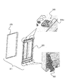
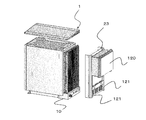
- FIG. 1A is a front perspective view of the housing 1, and FIG. 1B is a rear perspective view of the housing 1.
- FIG. 2 is an exploded perspective view of the housing 1.
- the housing 1 is a box mainly composed of an internal housing 2 and an exterior panel covering the internal housing 2, and has a substantially rectangular parallelepiped appearance as a whole.
- the inner casing 2 and the exterior panel are made of metal, and are made of stainless steel in this embodiment.
- the internal housing 2 includes a base (bottom) 10 having a substantially rectangular shape in plan view, a right side surface 11 and a left side surface 12 rising from two long sides of the base 10, and one short side of the base 10.
- 4 has a back surface 13 (FIG. 4B) that rises from the top and a ceiling surface 14 that faces the base 10, and a surface (front surface) that faces the back surface 13 is open.
- a reinforcing material is attached to the outside of each surface of the internal housing 2 as necessary.
- a back panel 23 is covered on the back surface 13 of the internal housing 2, and a ceiling panel 24 is covered on the ceiling surface 14.
- a front panel 25 is provided on the front surface of the internal housing 2.
- Each panel is fixed to each other by rivets or welding as required, or fixed to the inner casing 2.
- the front panel 25 is rotatably attached to the front surface of the internal housing 2. That is, the front panel 25 constitutes a lid 31 that opens and closes the opening 30 of the housing 1.
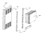
- a heat dissipating member described later is disposed between the back surface 13 (FIG. 4B) of the internal housing 2 and the back panel 23.
- the back panel 23 is formed with a plurality of slits 23a for communicating the heat dissipating member to the outside air. Has been.
- FIG. 3 is an exploded view showing the lid 31 of the housing 1 mainly composed of the front panel 25.
- the lid 31 includes a front panel 25 and a frame panel 26 that is fitted inside the front panel 25.
- Hooks 32 are provided on both sides of the lower end of the lid 31, and lock mechanisms 33 are provided on both sides of the upper end.
- the lid 31 can be rotated in the direction of the arrow in FIG. 2 with the shaft as a rotation axis by engaging each hook 32 with a shaft (not shown) provided at the lower edge of the housing opening 30. Is attached to the housing 1.
- the lock mechanism 33 in the present embodiment is a so-called snap lock, and snap lock receiving portions 33 a are provided on both sides of the upper end of the lid 31.
- a snap lock arm and lever are provided on the upper edge of the housing opening 30.
- the snap lock is locked by rotating the lever in a predetermined direction while the arm is hooked on the receiving portion 33a, and is unlocked by rotating the lever in the reverse direction.
- the lock mechanism 33 is not limited to the snap lock, and an arbitrary lock mechanism can be adopted.
- the back surface 13 of the internal housing 2 is provided with openings (upper opening 13a, lower opening 13b) at the top and bottom thereof. Further, a flange 13c having a height of about 40 mm is provided on the edge of the back surface 13.
- the heat radiating member 40 is accommodated inside the flange 13c, and the back panel 23 (FIG. 2) is covered from above. In other words, the heat radiating member 40 is disposed in a space 27 provided between the back surface 13 of the internal housing 2 and the back panel 23.
- the internal space of the housing 1 is divided into an inner space of the internal housing 2 and a space 27 by a partition wall (the back surface 13 of the internal housing 2).
- the two openings 13a and 13b communicate with each other.
- the heat dissipating member 40 includes a heat absorbing surface 41 and a heat dissipating surface 42 on which a large number of fins are formed, and the heat absorbing surface 41 is arranged in a direction facing the back surface 13. Moreover, the outer peripheral surface of the heat radiating member 40 is in close contact with the inner peripheral surface of the flange 13c. Further, a rubber packing 41 is provided between the end face of the flange 13c and the back panel 23 to ensure predetermined airtightness and watertightness.
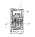
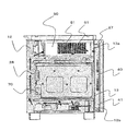
- FIG. 5 is a front view of the housing 1 with the lid 31 removed.
- the internal space of the housing 1, more precisely the inner space of the internal housing 2, is partitioned into three spaces along the vertical direction, the PCS unit 50 is accommodated in the upper stage, and the BMU 60 and a plurality of (this embodiment) 13 battery packs 70 are accommodated, and a terminal block (not shown) is accommodated in the lower stage.
- the internal structure of the housing 1, that is, the internal structure of the power storage device according to the present embodiment will be specifically described with reference to FIGS. 6A to 13.
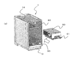
- the internal space of the housing 1 is divided into three spaces by a pair of plate-like members (an upper plate 80 and a lower plate 90). Specifically, the space (first space) between the upper plate 80 and the ceiling surface 14 of the inner casing 2, the space between the upper plate 80 and the lower plate 90 (second space), and the lower plate 90 and the base 10. It is partitioned into a space (third space) between them.
- the PCS unit 50 is accommodated in the first space while being fixed to the chassis 51.
- the chassis 51 to which the PCS unit 50 is fixed is slid along the upper surface of the upper plate 80 and inserted into the first space.
- the insertion operation is temporarily suspended before the PSC unit 50 is completely inserted into the first space, and necessary cables are connected to the PCS unit 50. Thereafter, the PSC unit 50 is completely inserted into the first space, and the chassis 51 is fixed to the upper plate 80 with screws.
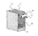
- FIG. 7A the BMU 60 is accommodated in the second space.
- the structures of the upper plate 80 and the lower plate 90 will be described in advance with reference to FIGS. 8A to 9C.
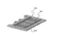
- 8A is a perspective view of the upper surface side of the upper plate 80
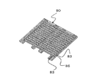
- FIG. 8B is a perspective view of the lower surface side of the upper plate 80
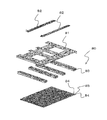
- FIG. 8C is an exploded perspective view of the upper plate 80.
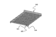
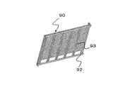
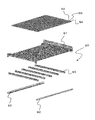
- 9A is a perspective view of the upper surface side of the lower plate 90
- FIG. 9B is a perspective view of the lower surface side of the lower plate 90
- FIG. 9C is an exploded perspective view of the lower plate 90.
- the upper plate 80 includes a base plate 81, a pair of brackets 82 provided on the upper surface of the base plate 81, and a plurality of support members 83 provided on the lower surface of the base plate 81. And a plurality of rail members 84 spanned on the support member 83.
- One end in the longitudinal direction of the bracket 82 is bent upward, and a screw hole (not shown) is formed at the bent end.
- a screw for fixing the chassis 51 (FIGS. 6A and 6B) on which the PCS unit 50 is mounted to the upper plate 80 is screwed into the screw hole.
- a plurality of support members 83 are arranged in parallel at a predetermined interval on the lower surface of the base plate 81.
- a plurality of rail members 84 are arranged in parallel at regular intervals along the longitudinal direction of the support member 83.
- Each rail member 84 has a substantially U-shaped cross-sectional shape, and a guide groove 85 is formed between the side walls of adjacent rail members 84. That is, 13 guide grooves 85 are provided in parallel on the lower surface of the upper plate 80 facing the upper surface of the lower plate 90.
- the lower plate 90 includes a base plate 91, a pair of brackets 92 provided on the lower surface of the base plate 91, and a plurality of supports passed between the pair of brackets 92.
- the member 93 includes a plurality of rail members 94 provided on the upper surface of the base plate 81.
- the plurality of support members 93 are arranged in parallel at predetermined intervals along the longitudinal direction of the brackets 92 between the opposing brackets 92.
- the plurality of rail members 94 are arranged in parallel at regular intervals along the longitudinal direction of the support member 93 on the upper surface of the base plate 91.
- Each rail member 94 has a substantially U-shaped cross-sectional shape, and a guide groove 95 is formed between the side walls of adjacent rail members 94. That is, 13 guide grooves 95 are provided in parallel on the upper surface of the lower plate 90 facing the lower surface of the upper plate 80.
- the guide grooves 85 provided in the upper plate 80 and the guide grooves 95 provided in the lower plate 90 correspond one to one.
- the end portions of the side walls of the rail members 84 and 94 are bent inward. As a result, the width of the ends (entrance / exit) of each guide groove 85, 95 is slightly wider than the width of the other portions.
- the BMU 60 is inserted into the second space along the left side surface 12 of the inner housing 2. As shown in FIG. 7A, the BMU 60 inserted into the second space is fixed to the end surfaces of the upper plate 80 and the lower plate 90 with screws (not shown).
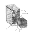
- each battery pack 70 has a substantially plate-like module case 71, and a film-covered battery (inside the recesses formed on the two main surfaces (A surface and B surface) of the module case 71. Lithium ion battery) 72 is arranged. More specifically, two concave portions are formed on each main surface of the module case 71, and one film-clad battery 72 is disposed in each concave portion.
- a substantially plate-like module case 71 and a film-covered battery (inside the recesses formed on the two main surfaces (A surface and B surface) of the module case 71.
- Lithium ion battery) 72 is arranged. More specifically, two concave portions are formed on each main surface of the module case 71, and one film-clad battery 72 is disposed in each concave portion.
- each battery pack 70 includes four film-clad batteries 72, and these four film-clad batteries 72 are connected in series via connection members (bus bars) provided in the case 71.
- connection members bus bars
- a sheet 73 is covered, and a cover 74 is covered on the insulating sheet 73.
- a handle 75 is integrally formed on the end surface of the module case 71.
- a plurality of battery packs 70 are arranged in parallel in the vertical direction.
- a plurality of battery packs 70 are arranged in parallel in the second space so that the A and B surfaces of adjacent battery packs 70 (module case 71) face each other.
- the battery packs 70 are arranged in parallel in the internal casing 2 in such a direction that the main surface thereof is parallel to the side surfaces 11 and 12 (FIG. 2) of the internal casing 2.
- the end surface in which the handle 75 is provided has opposed the opening surface of the housing opening part 30. FIG. That is, the handle 75 is exposed at the housing opening 30.
- the film-covered batteries may be bent due to the weight of the upper battery.
- each battery pack 70 arranged in parallel as described above is inserted into the guide groove 85 over its entire length, and the lower end (lower edge) is inserted into the guide groove 95 over its entire length.
- a slot in which each battery pack 70 can be inserted and removed is provided in the housing 1.
- the widths of the end portions (entrances / exits) of the guide grooves 85 and 95 are slightly wider than the widths of the other portions. Therefore, the end portion of each battery pack 70 can be easily inserted into the guide grooves 85 and 95 from the end portions of the guide grooves 85 and 95.
- FIG. 10 a plurality of battery packs 70 are shown integrally, but the battery packs 70 are independent of each other and can be inserted into and removed from the housing 1 independently.
- the plurality of battery packs 70 accommodated in the housing 1 are collectively fixed to the housing 1 by a pair of fixing members 101 and 102.
- the upper fixing member 101 straddling between the upper end surface of the battery pack 70 and the end surface of the upper plate 80 adjacent thereto is screwed to the end surface of the upper plate 80.
- a lower fixing member 102 straddling between the lower end surface of the battery pack 70 and the end surface of the lower plate 90 adjacent thereto is screwed to the end surface of the lower plate 90.
- Each of the battery packs 70 is fixed in the front-rear direction (in the insertion / removal direction to the housing 1) by these two fixing members 101, 102. It is obvious that each battery pack 70 is fixed in the left-right direction by the side walls of the rail members 84, 94 forming the guide grooves 85, 95.
- the plurality of battery packs 70 accommodated in the housing 1 are connected in series via a power cable 111 that connects connectors 110 provided on the end faces of the battery packs 70. At the same time, it is connected to the BMU 60 via the power cable.
- each battery pack 70 contains four film-clad batteries 72 connected in series. Therefore, the power storage device according to the present embodiment includes 52 (4 ⁇ 13) film-clad batteries 72 connected in series and has a maximum capacity of 6 kwh.
- a connector 112 different from the connector 110 is provided on the end face of each battery pack 70.
- the connectors 112 of the six battery packs 70 are connected to the connectors 114 of the BMU 60 via the signal cables 113, respectively, and the connectors 112 of the remaining seven battery packs 70 are connected to the connectors 115 of the BMU 60 via the signal cables 113, respectively.
- These connectors and cables are for sensing the state of each battery pack 70, and information indicating the state of each battery pack 70 is input to the BMU 60 via these connectors and cables.
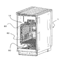
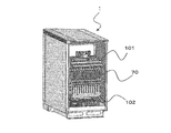
- a box 120 is attached to the outside of the back panel 23, and a notebook PC constituting a control system is accommodated in the box 120.
- a pair of brackets 121 are screwed to the outer surface of the back panel 23, and the box 120 is screwed to the brackets 121.
- the bracket 121 forms a gap between the back panel 23 and the box 120 so that the slit 23 a formed in the back panel 23 is not blocked by the box 120. It also has a role to play.
- the back surface of the base 10 is provided with a drawing hole for drawing a cable and a drawing hole for drawing the cable.
- the cable drawn from the drawing hole is connected to a predetermined terminal provided on the terminal block.
- a cable connected to a predetermined terminal provided on the terminal block is drawn out from the lead hole.
- the cooling structure of the power storage device according to this embodiment will be described.
- the performance of the film-clad battery accommodated in the housing 1 varies depending on the ambient temperature. Therefore, it is desirable to maintain the temperature in the housing 1 within a predetermined temperature range. In this case, if the internal space of the housing 1 is communicated with the outside air, the temperature rise of the internal space can be suppressed. However, if an opening or a through hole is provided for communicating the internal space of the housing 1 with the outside air, there is a concern that rainwater or dust may enter. Therefore, the casing 1 constituting the power storage device according to the present embodiment is sealed when the opening 30 is closed by the lid 31 and has a structure that ensures predetermined airtightness and watertightness.
- an opening or a through hole for communicating the internal space of the housing 1 with the outside air is not provided.
- the slit 23a (FIG. 1B, FIG. 2) provided in the back panel 23 is connected to the space 27 in which the heat radiating member 40 is arrange
- openings 13a and 13b are provided on the back surface 13 of the internal casing 2 forming the space 27.
- the heat dissipating member 40 is disposed on the back surface 13 and the outer peripheral surface of the heat dissipating member 40 is in close contact with the inner peripheral surface of the flange 13c.
- a packing 41 is disposed between the end face of the flange 13c and the back panel 23.
- the internal space of the housing 1 communicates with the heat dissipation member 40 but does not communicate with the outside air. More specifically, the heat absorbing surface 41 (FIG. 4A) of the heat radiating member 40 communicates with the internal space of the housing 1 through the openings 13a and 13b, and the heat radiating surface 42 (FIG. 4B) is connected through the slit 23a. It communicates with the open air. With this structure, the heat in the housing 1 can be dissipated to the outside without allowing the internal space of the housing 1 to communicate with the outside air.
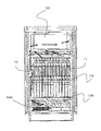
- FIGS. 15 and 16 an air flow as schematically shown by using arrows in FIGS. 15 and 16 is formed in the housing 1 to promote heat dissipation through the heat dissipation member 40. This will be specifically described below.
- FIG. 15 is a perspective view of the right side surface of the power storage device according to this embodiment
- FIG. 16 is a perspective view of the front surface.
- a suction port (not shown) and an exhaust port 52 are provided in the case of the PCS unit 50, and a cooling fan (not shown) is built in the case. Therefore, when the fan rotates, air is introduced from the intake port, and the introduced air is exhausted from the exhaust port 52.
- the first space of the housing 1 in which the PCS unit 50 is accommodated communicates with the space 27 in which the heat dissipation member 40 is accommodated via the upper opening 13a.
- the third space of the housing 1 in which the terminal block is accommodated communicates with the space 27 through the lower opening 13b.
- two fans 130 are provided in the third space of the casing 1 and in the vicinity of the lower opening 13b. That is, the upper and lower portions of the internal space of the housing 1 communicate with the space 27, and fans are provided at the upper and lower portions, respectively. Therefore, when two fans (the fan built in the PCS unit 50 and the fan 130) rotate, an air flow as shown by arrows in FIGS. 15 and 16 is generated in the housing 1 by the principle of push-pull. Specifically, the air blown out from the exhaust port 52 of the PCS unit 50 flows into the space 27 through the upper opening 13a. The air flowing into the space 27 passes through the space 27 and is sucked into the fan 130 through the lower opening 13b.
- the air blown out from the fan 130 passes below the electric pack 70 and flows out into the space 28 between the end face of the electric pack 70 and the front panel 25 (lid 31). Further, the air flowing into the space 28 passes through the space 28 and is sucked into the intake port of the PCS unit unit 50. That is, an airflow that circulates around the battery pack 70 is formed in the internal space of the housing 1.
- the airflow (air) circulating as described above is cooled by heat exchange with the outside air via the heat radiating member 40 when passing (falling) through the space 27.
- the cooled air mainly cools the battery pack 70 through heat exchange with the battery pack 70 in the process of passing (rising) through the space 28. That is, the spaces 27 and 28 form a flow path in the housing 1 for circulating air (cooling air).
- the back surface 13 of the internal housing 2 and the heat absorbing surface 41 of the heat dissipation member 40 facing the back surface 13 form a first flow path therebetween.
- the end surface of the battery pack 70 and the inner surface of the housing 1 (the inner surface of the lid 31) facing the end surface form a second flow path therebetween.
- the plurality of battery packs 70 can be cooled more uniformly than when the cooling air is directly supplied to the battery pack 70 and locally cooled. .
- the fan built in the PCS unit 50 is used to form the air flow.
- a fan built in the electronic device may be used.
- a fan different from the fan built in the electronic device may be provided and used.
- the exhaust port 52 of the PCS unit 50 and the upper opening 13a may be connected by a duct.
- a temperature sensor may be provided, and one or both of the two fans may be controlled based on the detection result of the sensor.
- a temperature sensor may be provided in the housing, and the operations of the two fans may be controlled based on the internal temperature of the housing 1 detected by the sensor.
- a temperature sensor may be provided outside the housing, and the operations of the two sensors may be controlled based on the environmental temperature detected by the sensor.
Landscapes
- Chemical & Material Sciences (AREA)
- Chemical Kinetics & Catalysis (AREA)
- Electrochemistry (AREA)
- General Chemical & Material Sciences (AREA)
- Engineering & Computer Science (AREA)
- Manufacturing & Machinery (AREA)
- Microelectronics & Electronic Packaging (AREA)
- Automation & Control Theory (AREA)
- Battery Mounting, Suspending (AREA)
- Secondary Cells (AREA)
- Sealing Battery Cases Or Jackets (AREA)
Abstract
Priority Applications (4)
| Application Number | Priority Date | Filing Date | Title |
|---|---|---|---|
| US13/818,031 US8951657B2 (en) | 2011-07-15 | 2012-06-18 | Battery apparatus |
| EP12814214.8A EP2725635A4 (fr) | 2011-07-15 | 2012-06-18 | Dispositif de stockage d'électricité |
| JP2013507485A JP5339492B2 (ja) | 2011-07-15 | 2012-06-18 | 蓄電装置 |
| US14/585,430 US20150111080A1 (en) | 2011-07-15 | 2014-12-30 | Battery apparatus |
Applications Claiming Priority (2)
| Application Number | Priority Date | Filing Date | Title |
|---|---|---|---|
| JP2011-156889 | 2011-07-15 | ||
| JP2011156889 | 2011-07-15 |
Related Child Applications (2)
| Application Number | Title | Priority Date | Filing Date |
|---|---|---|---|
| US13/818,031 A-371-Of-International US8951657B2 (en) | 2011-07-15 | 2012-06-18 | Battery apparatus |
| US14/585,430 Continuation US20150111080A1 (en) | 2011-07-15 | 2014-12-30 | Battery apparatus |
Publications (1)
| Publication Number | Publication Date |
|---|---|
| WO2013011779A1 true WO2013011779A1 (fr) | 2013-01-24 |
Family
ID=47557965
Family Applications (1)
| Application Number | Title | Priority Date | Filing Date |
|---|---|---|---|
| PCT/JP2012/065487 WO2013011779A1 (fr) | 2011-07-15 | 2012-06-18 | Dispositif de stockage d'électricité |
Country Status (4)
| Country | Link |
|---|---|
| US (2) | US8951657B2 (fr) |
| EP (1) | EP2725635A4 (fr) |
| JP (2) | JP5339492B2 (fr) |
| WO (1) | WO2013011779A1 (fr) |
Cited By (5)
| Publication number | Priority date | Publication date | Assignee | Title |
|---|---|---|---|---|
| JP2013077466A (ja) * | 2011-09-30 | 2013-04-25 | Sanyo Electric Co Ltd | 蓄電装置 |
| CN104733667A (zh) * | 2013-12-18 | 2015-06-24 | 古河电池株式会社 | 蓄电池收纳箱以及该蓄电池收纳箱所用的中央隔板 |
| WO2016068322A1 (fr) * | 2014-10-31 | 2016-05-06 | 日本電気株式会社 | Dispositif de stockage d'énergie |
| US20160226108A1 (en) * | 2013-09-24 | 2016-08-04 | Lg Chem, Ltd. | Battery pack including inserted type bms assembly |
| WO2016186139A1 (fr) * | 2015-05-19 | 2016-11-24 | 日本電気株式会社 | Dispositif de stockage d'énergie et structure de renforcement |
Families Citing this family (14)
| Publication number | Priority date | Publication date | Assignee | Title |
|---|---|---|---|---|
| DE102013114843A1 (de) * | 2013-12-23 | 2015-06-25 | Linde Material Handling Gmbh | Traktionsbatterie mit Batteriemanagementsystem |
| JPWO2015115466A1 (ja) * | 2014-01-29 | 2017-03-23 | 日本電気株式会社 | 蓄電池装置、電力変換装置、およびそれらを備えた蓄電システム |
| JP2015153508A (ja) * | 2014-02-12 | 2015-08-24 | 積水化学工業株式会社 | 建物用設備の化粧用カバー取付構造及び取付方法 |
| KR102171350B1 (ko) * | 2014-09-03 | 2020-10-29 | 에스케이이노베이션 주식회사 | 에너지 저장 시스템용 배터리 트레이 |
| US10020534B2 (en) | 2014-09-26 | 2018-07-10 | Johnson Controls Technology Company | Free floating battery cell assembly techniques for lithium ion battery module |
| US10103367B2 (en) | 2014-09-26 | 2018-10-16 | Johnson Controls Technology Company | Lithium ion battery module with free floating prismatic battery cells |
| DE102015214659A1 (de) * | 2015-07-31 | 2017-02-02 | Volkswagen Aktiengesellschaft | Traktionsbatterie mit einem Batteriegehäuse |
| KR102018721B1 (ko) * | 2016-05-31 | 2019-09-09 | 주식회사 엘지화학 | 배터리 모듈 및 이를 포함하는 배터리 팩, 자동차 |
| JP6928826B2 (ja) * | 2017-04-12 | 2021-09-01 | パナソニックIpマネジメント株式会社 | 電池モジュールおよび蓄電ユニット |
| JP6851020B2 (ja) | 2017-06-01 | 2021-03-31 | パナソニックIpマネジメント株式会社 | 蓄電池ユニット |
| JP7147273B2 (ja) * | 2018-05-30 | 2022-10-05 | 住友電気工業株式会社 | 蓄電システム |
| US11289933B2 (en) * | 2019-05-15 | 2022-03-29 | Ahmad Eivaz | Battery charging enclosure |
| EP4283769A3 (fr) * | 2022-05-23 | 2024-09-18 | Videndum Production Solutions Inc. | Centrale électrique à batterie modulaire refroidie passivement |
| CN116111264A (zh) * | 2023-02-13 | 2023-05-12 | 徐州力奥新能源设备有限公司 | 新能源电池固定结构 |
Citations (5)
| Publication number | Priority date | Publication date | Assignee | Title |
|---|---|---|---|---|
| JP2001256934A (ja) * | 2000-03-13 | 2001-09-21 | Osaka Gas Co Ltd | 電池モジュールケース |
| JP2006338934A (ja) * | 2005-05-31 | 2006-12-14 | Fuji Heavy Ind Ltd | 蓄電体セルのパッケージ構造 |
| JP2010182541A (ja) | 2009-02-05 | 2010-08-19 | Sanyo Electric Co Ltd | 蓄電装置 |
| JP2011210455A (ja) * | 2010-03-29 | 2011-10-20 | Yachiyo Industry Co Ltd | 電池セルモジュール |
| JP2012009311A (ja) * | 2010-06-25 | 2012-01-12 | Sanyo Electric Co Ltd | 蓄電システム |
Family Cites Families (13)
| Publication number | Priority date | Publication date | Assignee | Title |
|---|---|---|---|---|
| US5140744A (en) * | 1990-06-06 | 1992-08-25 | Miller Robert D | Modular multicell battery and rack |
| US5851695A (en) * | 1992-02-10 | 1998-12-22 | C & D Technologies, Inc. | Recombinant lead-acid cell and long life battery |
| US5366827A (en) * | 1992-06-10 | 1994-11-22 | Digital Equipment Corporation | Modular housing for batteries and battery charger |
| JPH078949U (ja) * | 1993-07-02 | 1995-02-07 | 山洋電気株式会社 | 蓄電池盤 |
| US6310783B1 (en) * | 2000-03-29 | 2001-10-30 | Powerware Corporation | Modular method and apparatus for building an uninterruptible power system (UPS) |
| JP3846435B2 (ja) * | 2003-03-07 | 2006-11-15 | 日本電気株式会社 | 引き出し付き収納庫及びその転倒防止装置 |
| US20060012334A1 (en) * | 2004-05-17 | 2006-01-19 | Railpower Technologies Corp. | Automated battery cell shunt bypass |
| JP4673019B2 (ja) * | 2004-09-10 | 2011-04-20 | 日立コンピュータ機器株式会社 | 情報処理装置 |
| JP2007257792A (ja) * | 2006-03-24 | 2007-10-04 | Hitachi Ltd | ストレージ装置 |
| JP5180505B2 (ja) * | 2007-03-30 | 2013-04-10 | 三菱重工業株式会社 | 電池モジュール |
| JP2010026941A (ja) * | 2008-07-23 | 2010-02-04 | Hitachi Ltd | 複数のバッテリモジュールを有するストレージシステム |
| JP2012009310A (ja) * | 2010-06-25 | 2012-01-12 | Sanyo Electric Co Ltd | 蓄電システム |
| US20120189888A1 (en) * | 2011-01-21 | 2012-07-26 | Dongguan Amperex Technology Limited | Battery cell of a lithium ion battery |
-
2012
- 2012-06-18 EP EP12814214.8A patent/EP2725635A4/fr not_active Withdrawn
- 2012-06-18 US US13/818,031 patent/US8951657B2/en active Active
- 2012-06-18 JP JP2013507485A patent/JP5339492B2/ja active Active
- 2012-06-18 WO PCT/JP2012/065487 patent/WO2013011779A1/fr active Application Filing
-
2013
- 2013-07-25 JP JP2013154709A patent/JP2013239454A/ja active Pending
-
2014
- 2014-12-30 US US14/585,430 patent/US20150111080A1/en not_active Abandoned
Patent Citations (5)
| Publication number | Priority date | Publication date | Assignee | Title |
|---|---|---|---|---|
| JP2001256934A (ja) * | 2000-03-13 | 2001-09-21 | Osaka Gas Co Ltd | 電池モジュールケース |
| JP2006338934A (ja) * | 2005-05-31 | 2006-12-14 | Fuji Heavy Ind Ltd | 蓄電体セルのパッケージ構造 |
| JP2010182541A (ja) | 2009-02-05 | 2010-08-19 | Sanyo Electric Co Ltd | 蓄電装置 |
| JP2011210455A (ja) * | 2010-03-29 | 2011-10-20 | Yachiyo Industry Co Ltd | 電池セルモジュール |
| JP2012009311A (ja) * | 2010-06-25 | 2012-01-12 | Sanyo Electric Co Ltd | 蓄電システム |
Non-Patent Citations (1)
| Title |
|---|
| See also references of EP2725635A4 |
Cited By (7)
| Publication number | Priority date | Publication date | Assignee | Title |
|---|---|---|---|---|
| JP2013077466A (ja) * | 2011-09-30 | 2013-04-25 | Sanyo Electric Co Ltd | 蓄電装置 |
| US20160226108A1 (en) * | 2013-09-24 | 2016-08-04 | Lg Chem, Ltd. | Battery pack including inserted type bms assembly |
| EP3035416A4 (fr) * | 2013-09-24 | 2016-08-10 | Lg Chemical Ltd | Bloc de batterie muni d'un groupe bms à insérer |
| US10116009B2 (en) | 2013-09-24 | 2018-10-30 | Lg Chem, Ltd. | Battery pack including inserted type BMS assembly |
| CN104733667A (zh) * | 2013-12-18 | 2015-06-24 | 古河电池株式会社 | 蓄电池收纳箱以及该蓄电池收纳箱所用的中央隔板 |
| WO2016068322A1 (fr) * | 2014-10-31 | 2016-05-06 | 日本電気株式会社 | Dispositif de stockage d'énergie |
| WO2016186139A1 (fr) * | 2015-05-19 | 2016-11-24 | 日本電気株式会社 | Dispositif de stockage d'énergie et structure de renforcement |
Also Published As
| Publication number | Publication date |
|---|---|
| EP2725635A1 (fr) | 2014-04-30 |
| US20130288087A1 (en) | 2013-10-31 |
| EP2725635A4 (fr) | 2015-01-28 |
| JP2013239454A (ja) | 2013-11-28 |
| US8951657B2 (en) | 2015-02-10 |
| JPWO2013011779A1 (ja) | 2015-02-23 |
| US20150111080A1 (en) | 2015-04-23 |
| JP5339492B2 (ja) | 2013-11-13 |
Similar Documents
| Publication | Publication Date | Title |
|---|---|---|
| JP5339492B2 (ja) | 蓄電装置 | |
| JP5881140B2 (ja) | 蓄電装置 | |
| US10347883B2 (en) | Battery-affixing frame member, battery-affixing member, and electricity storage device | |
| JP5632071B1 (ja) | 電力貯蔵装置 | |
| JP6782435B2 (ja) | 蓄電装置 | |
| EP2816632B1 (fr) | Logement pour un appareil de stockage d'énergie avec le partitionnement flexible | |
| JP5897551B2 (ja) | 電池パック | |
| JP5362377B2 (ja) | 蓄電装置 | |
| JP2005019562A (ja) | 電子機器の冷却構造 | |
| US10950907B2 (en) | Battery pack | |
| WO2013137448A1 (fr) | Dispositif de stockage électrique | |
| KR20140044465A (ko) | 무정전 전원장치용 배터리 캐비닛 | |
| JP6260625B2 (ja) | 電力貯蔵装置 | |
| US20180241104A1 (en) | Battery pack | |
| WO2016129385A1 (fr) | Dispositif de stockage d'énergie électrique | |
| JP5936114B2 (ja) | 蓄電装置 | |
| JP5971748B2 (ja) | 蓄電装置及び蓄電システム | |
| JP6323006B2 (ja) | 蓄電装置 | |
| CN109690866B (zh) | 电池单元和车辆用蓄电池装置 | |
| JP4312160B2 (ja) | 無停電電源装置 | |
| JP6785452B2 (ja) | 蓄電装置 | |
| JP6455282B2 (ja) | コンテナ型蓄電ユニット | |
| JP2011159482A (ja) | 電源装置及びこれを備える車両 | |
| JP2024016598A (ja) | 電気車両用充電装置 |
Legal Events
| Date | Code | Title | Description |
|---|---|---|---|
| ENP | Entry into the national phase |
Ref document number: 2013507485 Country of ref document: JP Kind code of ref document: A |
|
| REEP | Request for entry into the european phase |
Ref document number: 2012814214 Country of ref document: EP |
|
| WWE | Wipo information: entry into national phase |
Ref document number: 13818031 Country of ref document: US Ref document number: 2012814214 Country of ref document: EP |
|
| 121 | Ep: the epo has been informed by wipo that ep was designated in this application |
Ref document number: 12814214 Country of ref document: EP Kind code of ref document: A1 |
|
| NENP | Non-entry into the national phase |
Ref country code: DE |