WO2012176287A1 - エレベータ用巻き上げ機の支持装置 - Google Patents
エレベータ用巻き上げ機の支持装置 Download PDFInfo
- Publication number
- WO2012176287A1 WO2012176287A1 PCT/JP2011/064233 JP2011064233W WO2012176287A1 WO 2012176287 A1 WO2012176287 A1 WO 2012176287A1 JP 2011064233 W JP2011064233 W JP 2011064233W WO 2012176287 A1 WO2012176287 A1 WO 2012176287A1
- Authority
- WO
- WIPO (PCT)
- Prior art keywords
- hoisting machine
- seat plate
- plate
- machine base
- support device
- Prior art date
Links
Images


Classifications
-
- B—PERFORMING OPERATIONS; TRANSPORTING
- B66—HOISTING; LIFTING; HAULING
- B66B—ELEVATORS; ESCALATORS OR MOVING WALKWAYS
- B66B11/00—Main component parts of lifts in, or associated with, buildings or other structures
- B66B11/04—Driving gear ; Details thereof, e.g. seals
-
- B—PERFORMING OPERATIONS; TRANSPORTING
- B66—HOISTING; LIFTING; HAULING
- B66B—ELEVATORS; ESCALATORS OR MOVING WALKWAYS
- B66B11/00—Main component parts of lifts in, or associated with, buildings or other structures
- B66B11/0035—Arrangement of driving gear, e.g. location or support
- B66B11/004—Arrangement of driving gear, e.g. location or support in the machine room
Definitions
- This invention relates to a support device for an elevator hoist, and more particularly to a support device for a hoist that regulates the movement of the hoist during an earthquake.
- the anti-vibration rubber is inserted between the base receiver and the machine beam, the anti-vibration rubber upper plate and the base receiver are fixed by bolts, the anti-vibration rubber lower plate and the machine beam.
- the stopper bolt mounting seat is fixed to the vibration isolating rubber lower plate by welding or the like so that the stopper bolt mounting seat is located at the center of the vibration isolating rubber, and the stopper bolt penetrates through the hole formed in the base support. It is attached to a bolt mounting seat (for example, see Patent Document 1).
- the stopper bolt is inserted into a hole formed in the base receiver so as to be loosely fitted. Therefore, when the hoisting machine moves in the horizontal direction, the vertical direction, or the rotating direction, the stopper bolt The shaft portion of the winder is in contact with a hole formed in the base receiver, or the head of the stopper bolt is in contact with the base receiver, and the movement of the hoisting machine in the horizontal direction, the vertical direction, and the rotational direction is restricted. Therefore, the vibration-proof rubber is not excessively deformed, the vibration-proof rubber is prevented from being damaged or broken, and the hoisting machine is prevented from falling due to the vibration-proof rubber being broken or the like.
- the stopper bolt mounting seat is disposed at the center of the anti-vibration rubber, which complicates the anti-vibration rubber structure, resulting in an increase in cost.
- the hole for installing the stopper bolt mounting seat is formed in the center of the anti-vibration rubber, to ensure the same anti-vibration performance as the anti-vibration rubber without holes, the diameter of the anti-vibration rubber is It gets bigger by the minute. Furthermore, the vibration isolator rubber becomes larger, and the vibration isolator rubber upper plate and lower plate become larger, which increases the size of the support device. Further, in the conventional support device, since the stopper bolt for restricting movement is a separate part from the bolt for fixing the vibration isolating rubber upper plate to the base receiver, it is necessary to form a hole through which the stopper bolt is inserted in the base receiver.
- the present invention has been made to solve such a problem, and is used to move the hoisting machine using a spacer that is fixed to the upper plate of the antivibration rubber and connects the antivibration rubber and the hoisting machine base. It is an object of the present invention to provide an elevator hoisting machine support device that can regulate the vibration-proof rubber structure, simplify the vibration-proof rubber structure, reduce the size of the anti-vibration rubber structure, and reduce mounting holes for the hoisting machine base.
- a support device for an elevator hoisting machine is configured by sandwiching a rubber material between an upper seat plate and a lower seat plate, and placing the lower seat plate on a flange of a machine base.
- the other end has a cylindrical spacer fixed to the hoisting machine base, a movement restricting hole, is fixed to the lower seat plate, extends between the upper seat plate and the hoisting machine base, and the spacer Is provided with a movement restricting plate inserted into the movement restricting hole in a loosely fitted state.
- the movement restricting hole is formed in the movement restricting plate that is fixed to the lower seat plate and extends between the upper seat plate and the hoisting machine base, and the spacer that connects the upper seat plate and the hoisting machine base is moved.
- the movement of the hoisting machine is regulated by inserting the regulation hole in a loosely fitted state. Therefore, since the anti-vibration rubber does not constitute a movement restricting mechanism, the structure of the anti-vibration rubber can be simplified, and the cost and size can be reduced.
- a mounting hole formed on the hoisting machine base Is only a bolt insertion hole for fastening and fixing the spacer.
- FIG. 2 is a cross-sectional view taken along the line II-II in FIG. It is the A section enlarged view of FIG. It is a side view which shows the support apparatus of the elevator hoisting machine which concerns on Embodiment 2 of this invention.
- FIG. 5 is a cross-sectional view taken along line VV in FIG. 4. It is a side view which shows the support apparatus of the elevator hoisting machine which concerns on Embodiment 3 of this invention.
- FIG. 7 is a sectional view taken along arrow VII-VII in FIG. 6.
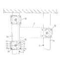
- FIG. 1 is a side view showing a support device for an elevator hoist according to Embodiment 1 of the present invention
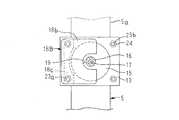
- FIG. 2 is a sectional view taken along the line II-II in FIG. 1
- FIG. 3 is an enlarged view of a portion A in FIG. .
- the hoisting machine 1 is fixed to a T-shaped hoisting machine base 3, and a main rope 4 for suspending a car (not shown) and a counterweight (not shown) is a driving sheave 2. It is wrapped around
- the machine base 5 is made of H-shaped steel, arranged in parallel, and fixed to the machine room floor 6 above the hoistway 8 with anchor bolts (not shown).
- the hoisting machine base 3 is placed on one machine base 5 on one side of the T-shape, and the extending end of the other side extending from the center of one side is placed on the other machine base 5.
- the hoisting machine base 3 is supported by the machine base 5 via the support device 10 at the two ends of one side of the T-shape and the tip of the other side.
- the support device 10 connects the anti-vibration rubber 11 attached to the flange 5a of the machine base 5, the fastening means for fastening the anti-vibration rubber 11 to the flange 5a, and the anti-vibration rubber 11 and the hoisting machine base 3.
- a spacer 16 and a movement restricting plate 18 that engages with the spacer 16 and restricts the movement of the hoist 1 due to an earthquake or the like are provided.
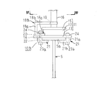
- the anti-vibration rubber 11 includes a cylindrical rubber member 12, a rectangular flat plate lower base plate 13 fixed to the lower surface of the rubber member 12, and a circular flat upper member fixed to the upper surface of the rubber member 12. And a plate 15. Mounting through holes 14 are formed at the four corners of the lower seat plate 13.
- the spacer 16 is formed in a columnar shape, and is fixed to the upper seat plate 15 by welding or the like, and is erected coaxially with the axis of the rubber material 12.
- the female screw portion 17 is formed at the axial center position of the spacer 16 with the screw hole direction as the axial direction.
- the movement restricting plate 18 is formed in a rectangular flat plate shape and has a notch 19 as a movement restricting hole.
- the notch 19 has a groove width larger than the diameter of the spacer 16 and is formed in a hole shape having one end opened at the center of the edge of one side of the movement restricting plate 18 and a semicircular bottom at the other end.
- the through-hole 20 for attachment is formed in the edge part of the edge
- the clip member 21 is formed in an L shape having a base portion 21a and a sandwiching portion 21b extending from one side in the thickness direction of the base portion 21a, and the through hole 22 is formed so as to penetrate the base portion 21a in the thickness direction. ing.
- the clip member 21, the mounting bolts 23a and 23b, and the nut 24 constitute fastening means.
- the shaft portion of the mounting bolt 23a is longer than the shaft portion of the mounting bolt 23b.
- the anti-vibration rubber 11 is placed on the flange 5a of the machine base 5, the base portion 21a of the clip member 21 is directed to the lower surfaces of the four corners of the lower seat plate 13, and the flange 5a is connected to the lower seat plate 13 and the sandwiching portion 21b.
- the mounting bolts 23a and 23b are inserted into the through hole 22 formed in the base 21a of the clip member 21 and the through hole 14 formed in the lower seat plate 13, and the mounting bolts 23a and 23b and the nut 24 are tightened. It is fixed to the machine base 5.
- the two mounting bolts 23 a extend in parallel so that the shaft portion passes through the outside of the upper seat plate 15 and faces the spacer 16.
- the movement restricting plate 18 is positioned so that the center of the semicircular bottom portion of the notch 19 is aligned with the axis of the vibration isolating rubber 11 through the mounting bolt 23a through the through hole 20, and sandwiches the movement restricting plate 18 therebetween.
- the pair of nuts 24 screwed to the shaft portion of the mounting bolt 23a are fastened and fixed to the two mounting bolts 23a.
- the spacer 16 is accommodated in the notch 19 such that its axis coincides with the center of the semicircular bottom of the notch 19.
- a mounting bolt (not shown) is passed through a through hole (not shown) formed in the hoisting machine base 3 and fastened to the female screw portion 17, and the hoisting machine base 3 is connected to the machine base via the support device 10. 5 is supported.
- the movement restricting plate 18 of the supporting device 10 that supports both ends of one side of the T-shape of the hoisting machine base 3 extends in the U-shaped groove depth direction of the notch 19 in the T-shape of the hoisting machine base 3. Is arranged in parallel with the extending direction of the other side extending from the center of one side, and the opening of the notch 19 is arranged toward the extending end side of the other side of the T-shape of the hoisting machine base 3. .
- the movement restricting plate 18 of the support device 10 that supports the extending portion of the other side of the T-shape of the hoisting machine base 3 extends in the U-shaped groove depth direction of the notch 19 in the T-shape of the hoisting machine base 3.
- the other side of the winding is parallel to the extending direction, and the opening of the notch 19 is disposed toward one side of the T-shape of the hoisting machine 3.
- the through hole 20 is formed as an elongated hole in which both ends of two parallel lines are connected by a semicircle, and the movement restricting plate 18 is positioned at the center of the semicircular bottom of the notch 19 with the axis of the spacer 16 being centered.
- the position is adjusted and fixed to the mounting bolt 23a.
- vibration generated in the hoisting machine 1 is transmitted to the anti-vibration rubber 11 through the hoisting machine base 3 and the spacer 16.
- the vibration is absorbed by the rubber material 12 of the anti-vibration rubber 11 and the vibration is prevented from propagating to the machine base 5.
- the hoisting machine 1 fixed to the hoisting machine base 3 is greatly shaken.
- the hoisting machine base 3 and the spacer 16 fixed to the hoisting machine base 3 move in the horizontal direction in synchronization with the hoisting machine 1.
- the moving force in the horizontal direction of the spacer 16 acts on the rubber material 12 via the upper seat plate 15 to deform the rubber material 12.
- the rotational force of the hoisting machine 1 acts on the rubber material 12 via the spacer 16 and the upper seat plate 15 to deform the rubber material 12.
- the spacer 16 is located at the bottom of the semicircular bottom of the notch 19 in any one of the supporting devices 10 that support the hoisting machine base 3 at three points. Contact the inner wall surface. Therefore, the rotational force of the hoisting machine 1 after the spacer 16 contacts the inner wall surface of the semicircular bottom of the notch 19 does not act so as to deform the rubber material 12.
- the moving force of the hoisting machine 1 acts on the rubber material 12 via the spacer 16 and the upper seat plate 15 to deform the rubber material 12.
- the hoisting machine base 3 or the upper seat plate 15 comes into contact with the movement restricting plate 18. Therefore, the moving force of the hoisting machine 1 after the hoisting machine base 3 or the upper seat plate 15 comes into contact with the movement restricting plate 18 does not act so as to deform the rubber material 12.
- the support device 10 can regulate the movement of the hoist 1 in the horizontal direction, the vertical direction, and the rotation direction. Therefore, even if an exciting force such as an earthquake is applied to the hoisting machine 1, even if the hoisting machine 1 moves in the horizontal direction, the vertical direction, or rotates, the support device 10 transmits a force that excessively deforms the rubber material 12. Therefore, the amount of deformation of the rubber material 12 is suppressed, and a situation where damage or breakage is prevented is prevented. As a result, a situation in which the rubber material 12 is greatly deformed, damaged or broken and the hoist 1 falls over can be avoided.
- the support device 10 does not need to have a special structure in which the spacer bolt mounting seat is embedded in the center of the vibration-proof rubber unlike the conventional support device, and the vibration-proof rubber 11 can be realized with a simple configuration. Miniaturization and cost reduction are achieved.
- the support device 10 is erected from the axial center position of the upper seat plate 15 of the anti-vibration rubber 11 and uses a spacer 16 that is fixed to the hoisting machine base 3, so that the hoisting machine 1 is horizontally, vertically, and rotated.
- a movement restricting mechanism for restricting the movement of the head Therefore, the vibration isolating mechanism and the movement restricting mechanism are coaxial, and an increase in the radial dimension of the support device 10 is suppressed, and the size can be reduced.
- the support device 10 is installed in place of the existing support device that does not include the movement restriction mechanism, a situation in which the support device 10 interferes with the wall 7 of the machine room is avoided.
- the support device 10 uses the spacer 16 fixed to the hoisting plate 15 and fixed to the hoisting machine base 3 for the movement restriction mechanism, the hoisting machine base 3 is attached to the hoisting machine base 3 in order to attach the supporting device 10 to the hoisting machine base 3.
- the bolt insertion holes formed in the above are only bolt insertion holes for fastening the spacer 16. Therefore, when the present support device 10 is installed in place of the existing support device that does not include the movement restriction mechanism, a bolt insertion hole formed in the hoisting machine base 3 for attaching the existing support device to the hoisting machine base 3 is provided. It is possible to simply install the support device 10. As a result, no additional drilling is required, and the installation workability of the support device 10 is improved.
- the groove width of the notch 19 that is, the diameter of the bottom of the semicircular shape
- setting of the horizontal moving force in which the spacer 16 contacts the wall surface of the bottom of the notch 19 and the rotational force in the horizontal plane is set.
- the value can be set arbitrarily.
- the gap between the movement restricting plate 18 and the upper seat plate 15 and the gap between the movement restricting plate 18 and the hoisting machine base 3 the upper and lower portions where the movement restricting plate 18 contacts the upper seat plate 15 or the hoisting machine base 3.
- the set value of the direction moving force can be set arbitrarily.
- the three points of the hoisting machine base 3 are supported by the machine base 5 via the support device 10, but the supporting devices 10 are arranged at all three points of the hoisting machine base 3. Even if the support device 10 is arranged at two points so that the groove direction of the notch 18 is reversed, and the support device without the movement restriction mechanism is arranged at the remaining one point, the horizontal direction, The movement in the rotational direction and the vertical direction can be restricted.
- the four corners of the hoisting machine base are supported by the machine base 5 via the supporting device, but it is not necessary to use the present supporting device 10 for all the supporting devices. .
- the support device 10 is arranged at two points so that the groove direction of the notch 18 is opposite, and the support device without the movement restriction mechanism is arranged at the remaining two points, the horizontal direction, the rotation direction, The movement in the vertical direction can be restricted.
- FIG. 4 is a side view showing a support device for an elevator hoist according to Embodiment 2 of the present invention
- FIG. 5 is a cross-sectional view taken along line VV in FIG.
- the anti-vibration rubber 11 clips the flange 5a of the machine base 5 between the lower seat plate 13 and the clip portion 21b of the clip base 21 at the four corners of the lower seat plate 13, and clips the mounting bolt 23a. It is inserted into the through hole 22 formed in the base portion 21 a of the member 21 and the through hole 14 formed in the lower seat plate 13, and the mounting bolt 23 a and the nut 24 are fastened and fixed to the machine base 5.
- the movement restricting plate 18A is formed in a rectangular flat plate shape, a circular movement restricting hole 25 having a diameter larger than that of the spacer 16 is formed at substantially the center of the movement restricting plate 18A, and the mounting through hole 20 is formed on the movement restricting plate 18A. It is formed at four corners.
- the movement restricting plate 18A passes the mounting bolt 23a through the through hole 20, is positioned so that the center of the movement restricting hole 25 coincides with the axis of the vibration isolating rubber 11, and the mounting bolt 23a is sandwiched between the movement restricting plate 18A.
- a pair of nuts 24 screwed to the shaft portion of the shaft are fastened and fixed to the mounting bolts 23a.
- Other configurations are the same as those in the first embodiment.
- the spacer 16 comes into contact with the inner wall surface of the movement restricting hole 25 of the movement restricting plate 18A.
- the spacer 16 is moved by the movement restricting plate 18A in any one of the supporting devices 10A of the supporting device 10A that supports the hoisting machine base 3 at three points. It contacts the inner wall surface of the movement restricting hole 25.
- the movement restricting plate 18A comes into contact with the upper seat plate 15 or the hoisting machine base 3.
- the support device 10A provided with the movement restricting mechanism can be realized with a simple structure, and the same effect as in the first embodiment can be obtained.
- the movement restricting plate 18A is supported by the four mounting bolts 23a, the rigidity of the movement restricting structure by the movement restricting plate 18A is increased, and the horizontal and vertical directions of the hoist 1 are increased. And movement in the rotational direction can be reliably regulated.
- FIG. 6 is a side view showing a support device for an elevator hoist according to Embodiment 3 of the present invention
- FIG. 7 is a cross-sectional view taken along arrow VII-VII in FIG.
- the movement restricting plate 18B is formed in a U-shape in which the movement restricting portion 18b and the attachment portion 18c extend in the same direction from both ends of the web 18a, and has a groove width larger than the diameter of the spacer 16.
- a U-shaped notch 19 is formed so as to open in the center in the length direction of the extension end of the movement restricting portion 18b, and a mounting through hole 20 is formed in the mounting portion 18c so as to be spaced apart in the length direction.
- the length direction is a direction orthogonal to both directions of the direction in which the movement restricting portion 18b and the mounting portion 18c face each other and the direction in which the movement restricting portion 18b and the attaching portion 18c extend from the web 18a.
- the movement restricting plate 18B is positioned so that the mounting portion 18c is directed to the lower seat plate 13, the center of the semicircular bottom portion of the notch 19 is aligned with the axis of the vibration isolating rubber 11, and the base portion 21a of the clip member 21 is located.
- the mounting bolt 23a and the nut 24 passed through the through hole 22 formed in the through hole 22, the through hole 14 formed in the lower seat plate 13, and the through hole 20 formed in the mounting portion 18c are tightened.
- the flange 5a is fastened together.
- Other configurations are the same as those in the first embodiment.
- the spacer 16 contacts the inner wall surface of the semicircular bottom of the notch 19 formed in the movement restricting portion 18b of the movement restricting plate 18B.
- the spacer 16 is moved by the movement restricting plate 18B in any one of the supporting devices 10B of the supporting device 10B that supports the hoisting machine base 3 at three points.
- the movement restricting portion 18b is in contact with the inner wall surface of the semicircular bottom portion of the notch 19. Further, when the moving force in the vertical direction of the hoisting machine 1 exceeds the set value, the movement restricting portion 18b of the movement restricting plate 18B comes into contact with the upper seat plate 15 or the hoisting machine base 3.
- the support device 10B provided with the movement restricting mechanism in addition to the vibration isolating mechanism can be realized with a simple structure, and the same effect as in the first embodiment can be obtained.
- the mounting portion 18c of the movement restricting plate 18B is fastened together with the lower seat plate 13 of the vibration isolating rubber 11 to the flange 5a of the machine base 5, the number of nuts 24 is reduced. Installation workability is improved.
- the machine base is fixed to the floor of the machine room.
- the machine base is installed so as to cross the hoistway. . That is, the machine base is fixed to the building so as to cross the hoistway.
Landscapes
- Engineering & Computer Science (AREA)
- Civil Engineering (AREA)
- Mechanical Engineering (AREA)
- Structural Engineering (AREA)
- Cage And Drive Apparatuses For Elevators (AREA)
- Lift-Guide Devices, And Elevator Ropes And Cables (AREA)
Abstract
この発明は、防振ゴムの上座板に固着されて、防振ゴムと巻き上げ機台とを連結するスペーサを用いて巻き上げ機の移動を規制できるようにし、防振ゴム構造の単純化および小型化を図るとともに、巻き上げ機台に対する取付用の穴加工を削減できるエレベータ用巻き上げ機の支持装置を得る。 この発明によるエレベータ用巻き上げ機の支持装置は、ゴム材を上座板と下座板とで挟持して構成され、下座板を機械台のフランジに載置して配設される防振ゴムと、下座板をフランジに締着固定する締着手段と、軸方向を防振ゴムの中心に一致させて一端が上座板に固着されて上座板に立設され、他端が巻き上げ機台に固定される円柱状のスペーサと、移動規制穴を有し、下座板に固定されて上座板と巻き上げ機台との間に延在し、スペーサが移動規制穴内に遊嵌状態に挿通される移動規制板と、を備えている。
Description
この発明は、エレベータ用巻き上げ機の支持装置に関し、特に地震の際に巻き上げ機の移動を規制する巻き上げ機の支持装置に関するものである。
従来のエレベータ用巻き上げ機の支持装置では、防振ゴムがベース受けとマシーンビームとの間に挿入され、防振ゴム上板とベース受けとがボルトにより固定され、防振ゴム下板とマシーンビームとがボルトにより固定され、ストッパーボルト取付用座が防振ゴムの中心に位置するように防振ゴム下板に溶接などより固定され、ストッパーボルトがベース受けに形成された穴を貫通してストッパーボルト取付用座に取り付けられている(例えば、特許文献1参照)。
従来のエレベータ用巻き上げ機の支持装置では、ストッパーボルトがベース受けに形成された穴に遊嵌状態に挿入されているので、巻き上げ機が水平方向、上下方向、あるいは回転方向に移動すると、ストッパーボルトの軸部がベース受けに形成された穴に当接し、あるいはストッパーボルトの頭部がベース受けに当接し、巻き上げ機の水平方向、上下方向、および回転方向の移動が規制される。そこで、防振ゴムに過大な変形が生じず、防振ゴムの損傷や破断の発生が防止され、防振ゴムの破断などによる巻き上げ機の転倒が防止される。
従来のエレベータ用巻き上げ機の支持装置では、ストッパーボルト取付用座が防振ゴムの中心に配設されており、防振ゴム構造が複雑となり、コスト増をもたらしていた。
また、ストッパーボルト取付用座を設置する穴が防振ゴムの中心に形成されているので、穴のない防振ゴムと同等の防振性を確保するには、防振ゴムの径が穴の分だけ大きくなる。さらに、防振ゴムが大きくなる分、防振ゴム上板および下板が大きくなり、支持装置が大型化してしまう。さらに、従来の支持装置では、移動規制用のストッパーボルトが防振ゴム上板をベース受けに固定するボルトと別部品であるので、ストッパーボルトを挿通する穴をベース受けに形成する必要がある。
そこで、巻き上げ機の水平方向、上下方向、および回転方向の移動を規制する機構を有しない既設の支持装置に代えて従来の支持装置を据え付けようとすると、建物の壁と干渉する事態が発生したり、追加の穴加工が必要となり、据え付け作業性が低下してしまう。
この発明は、このような課題を解決するためになされたものであって、防振ゴムの上座板に固着されて、防振ゴムと巻き上げ機台とを連結するスペーサを用いて巻き上げ機の移動を規制できるようにし、防振ゴム構造の単純化および小型化を図るとともに、巻き上げ機台に対する取付用の穴加工を削減できるエレベータ用巻き上げ機の支持装置を得ることを目的とする。
この発明に係るエレベータ用巻き上げ機の支持装置は、ゴム材を上座板と下座板とで挟持して構成され、該下座板を機械台のフランジに載置して配設される防振ゴムと、上記下座板を上記フランジに締着固定する締着手段と、軸方向を上記防振ゴムの中心に一致させて一端が上記上座板に固着されて該上座板に立設され、他端が上記巻き上げ機台に固定される円柱状のスペーサと、移動規制穴を有し、上記下座板に固定されて上記上座板と上記巻き上げ機台との間に延在し、上記スペーサが該移動規制穴内に遊嵌状態に挿通される移動規制板と、を備えている。
この発明によれば、下座板に固定されて上座板と巻き上げ機台との間に延在する移動規制板に移動規制穴を形成し、上座板と巻き上げ機台とを連結するスペーサを移動規制穴内に遊嵌状態に挿通させて、巻き上げ機の移動を規制している。そこで、防振ゴムが移動規制機構を構成していないので、防振ゴムの構造を単純化でき、低コスト化および小型化を図ることができる。
また、巻き上げ機の振動を防振ゴムに伝達するスペーサが移動規制穴の内壁面に当接して巻き上げ機の移動を規制する部材を兼ねているので、巻き上げ機台に形成される取付用の穴はスペーサを締着固定するボルト挿通用の穴のみとなる。これにより、巻き上げ機の移動を規制する機構を有しない既設の支持装置に代えて本支持装置を据え付ける場合、既設の支持装置を取り付けるために巻き上げ機台に形成されていた穴を流用できるので、追加の穴加工が不要となり、据え付け作業性が向上される。また、また、防振機構と移動規制機構とが同軸となり、支持装置の径方向の寸法の増大が抑えられ、小型化が図られるので、据え付けられる本支持装置が建物の壁と干渉することもない。
以下、本発明のエレベータ用巻き上げ機の支持装置の好適な実施の形態につき図面を用いて説明する。
実施の形態1.
図1はこの発明の実施の形態1に係るエレベータ用巻き上げ機の支持装置を示す側面図、図2は図1のII-II矢視断面図、図3は図1のA部拡大図である。
図1はこの発明の実施の形態1に係るエレベータ用巻き上げ機の支持装置を示す側面図、図2は図1のII-II矢視断面図、図3は図1のA部拡大図である。
図1乃至図3において、巻き上げ機1は、T字状の巻き上げ機台3に固定され、乗りかご(図示せず)およびつり合いおもり(図示せず)を懸架する主ロープ4が駆動綱車2に巻き掛けられている。
機械台5は、H形鋼で作製され、平行に並べられてアンカーボルト(図示せず)で昇降路8の上部の機械室の床6に固定されている。巻き上げ機台3は、T字状の一辺を一方の機械台5に載置され、一辺の中央から延出する他辺の延出端を他方の機械台5に載置されている。そして、巻き上げ機台3は、T字状の一辺の両端部および他辺の先端部の3箇所を支持装置10を介して機械台5に支持されている。
機械台5は、H形鋼で作製され、平行に並べられてアンカーボルト(図示せず)で昇降路8の上部の機械室の床6に固定されている。巻き上げ機台3は、T字状の一辺を一方の機械台5に載置され、一辺の中央から延出する他辺の延出端を他方の機械台5に載置されている。そして、巻き上げ機台3は、T字状の一辺の両端部および他辺の先端部の3箇所を支持装置10を介して機械台5に支持されている。
支持装置10は、機械台5のフランジ5aに取り付けられる防振ゴム11と、防振ゴム11をフランジ5aに締着固定する締着手段と、防振ゴム11と巻き上げ機台3とを連結するスペーサ16と、スペーサ16と係合し、地震などによる巻き上げ機1の移動を規制する移動規制板18と、を備えている。
防振ゴム11は、円柱状に作製されたゴム材12と、ゴム材12の下面に固着された矩形平板状の下座板13と、ゴム材12の上面に固着された円形平板状の上座板15と、を備えている。取付用の貫通穴14が、下座板13の4隅に形成されている。スペーサ16は、円柱状に作製され、上座板15に溶接などにより固着されてゴム材12の軸心と同軸に立設されている。雌ねじ部17が、ねじ穴方向を軸方向としてスペーサ16の軸心位置に形成されている。
移動規制板18は、矩形平板状に作製され、移動規制穴としての切り欠き19を有する。切り欠き19は、スペーサ16の直径より大きな溝幅を有し、一端を移動規制板18の一辺の縁部の中央に開口し、他端に半円形の底部を有する穴形状に形成されている。さらに、取付用の貫通穴20が移動規制板18の切り欠き19の底部に相対する辺の縁部に当該辺の長さ方向に離間して形成されている。
クリップ部材21は、基部21aと、基部21aの厚み方向の一側から延出する挟み部21bとを有するL字状に作製され、貫通穴22が基部21aを厚み方向に貫通するように形成されている。なお、クリップ部材21、取付ボルト23a,23b、およびナット24が締着手段を構成する。また、取付ボルト23aの軸部は取付ボルト23bの軸部より長くなっている。
防振ゴム11は、機械台5のフランジ5a上に載置され、クリップ部材21の基部21aを下座板13の4隅の下面に宛がい、フランジ5aを下座板13と挟み部21bとで挟み込み、取付ボルト23a,23bをクリップ部材21の基部21aに形成された貫通穴22と下座板13に形成された貫通穴14に挿入し、取付ボルト23a,23bとナット24を緊締して、機械台5に固定されている。そして、2本の取付ボルト23aは、軸部が上座板15の外側を通り、スペーサ16に相対するように、かつ平行に延在している。
そして、移動規制板18は、貫通穴20に取付ボルト23aを通し、切り欠き19の半円形の底部の中心を防振ゴム11の軸心に一致するように位置決めされ、移動規制板18を挟み込むように取付ボルト23aの軸部に螺着された一対のナット24を緊締して、2本の取付ボルト23aに固定されている。これにより、スペーサ16は、その軸心が切り欠き19の半円形の底部の中心に一致して、切り欠き19内に収容されている。さらに、取付ボルト(図示せず)を巻き上げ機台3に形成された貫通穴(図示せず)に通して、雌ねじ部17に締着し、巻き上げ機台3が支持装置10を介して機械台5に支持されている。
ここで、巻き上げ機台3のT字状の一辺の両端部を支持する支持装置10の移動規制板18は、切り欠き19のU字状の溝深さ方向を巻き上げ機台3のT字状の一辺の中央から延出する他辺の延出方向と平行とし、かつ切り欠き19の開口を巻き上げ機台3のT字状の他辺の延出端側に向けて、配設されている。また、巻き上げ機台3のT字状の他辺の延出部を支持する支持装置10の移動規制板18は、切り欠き19のU字状の溝深さ方向を巻き上げ機台3のT字状の他辺の延出方向と平行とし、かつ切り欠き19の開口を巻き上げ機台3のT字状の一辺側に向けて、配設されている。
さらに、貫通穴20は2本の平行線の両端を半円で連結した長穴に形成され、移動規制板18は、スペーサ16の軸心が切り欠き19の半円形の底部の中心に位置するように位置調整されて、取付ボルト23aに固定されている。
つぎに、支持装置10の動作について説明する。
まず、巻き上げ機1で発生する振動は、巻き上げ機台3およびスペーサ16を介して防振ゴム11に伝達される。そして、振動は、防振ゴム11のゴム材12により吸収され、振動が機械台5に伝播するのが防止される。
まず、巻き上げ機1で発生する振動は、巻き上げ機台3およびスペーサ16を介して防振ゴム11に伝達される。そして、振動は、防振ゴム11のゴム材12により吸収され、振動が機械台5に伝播するのが防止される。
例えば、地震などにより加振されると、支持装置10より上部の部材、すなわち巻き上げ機台3に固定された巻き上げ機1が大きく揺れる。
このとき、巻き上げ機1が水平方向に移動すると、巻き上げ機台3および巻き上げ機台3に固着されているスペーサ16が巻き上げ機1に同期して水平方向に移動する。そして、スペーサ16の水平方向の移動力が上座板15を介してゴム材12に作用し、ゴム材12を変形させる。
このとき、巻き上げ機1が水平方向に移動すると、巻き上げ機台3および巻き上げ機台3に固着されているスペーサ16が巻き上げ機1に同期して水平方向に移動する。そして、スペーサ16の水平方向の移動力が上座板15を介してゴム材12に作用し、ゴム材12を変形させる。
そして、巻き上げ機1の水平方向の移動力が設定値より大きくなると、スペーサ16が移動規制板18の切り欠き19の半円形の底部の内壁面に当接し、巻き上げ機1の水平方向の移動力は、スペーサ16、移動規制板18、取付ボルト23a、下座板13を介して機械台5に伝達される。そこで、ゴム材12は巻き上げ機1に同期して水平方向に移動するので、スペーサ16が切り欠き19の半円形の底部の内壁面に当接した後の巻き上げ機1の水平方向の移動力はゴム材12を変形させるように作用しない。
また、巻き上げ機1が水平面内で回転すると、巻き上げ機1の回転力は、スペーサ16および上座板15を介してゴム材12に作用し、ゴム材12を変形させる。そして、巻き上げ機1の回転力が設定値より大きくなると、巻き上げ機台3を3点支持している支持装置10のいずれかの支持装置10で、スペーサ16が切り欠き19の半円形の底部の内壁面に当接する。そこで、スペーサ16が切り欠き19の半円形の底部の内壁面に当接した後の巻き上げ機1の回転力はゴム材12を変形させるように作用しない。
また、巻き上げ機1が上下方向に移動すると、巻き上げ機1の移動力は、スペーサ16および上座板15を介してゴム材12に作用し、ゴム材12を変形させる。そして、巻き上げ機1の上下方向の移動力が設定値より大きくなると、巻き上げ機台3又は上座板15が移動規制板18に当接する。そこで、巻き上げ機台3又は上座板15が移動規制板18に当接した後の巻き上げ機1の移動力はゴム材12を変形させるように作用しない。
このように、支持装置10は、巻き上げ機1の水平方向、上下方向、および回転方向の移動を規制することができる。そこで、地震などの加振力が巻き上げ機1に加わり、巻き上げ機1が水平方向や上下方向に移動し、あるいは回転しても、支持装置10がゴム材12を過度に変形させる力の伝達を阻止するので、ゴム材12の変形量が抑えられ、損傷、あるいは破断に至るような事態が防止される。その結果、ゴム材12が大きく変形し、損傷し、あるいは破断し、巻き上げ機1が転倒するような事態が未然に回避される。
支持装置10は、従来の支持装置のように、スペーサボルト取付用座を防振ゴムの中心に埋設するような特殊な構造をとる必要がなく、防振ゴム11を簡易な構成で実現でき、小型化および低コスト化が図られる。
支持装置10は、防振ゴム11の上座板15の軸心位置から立設されて、巻き上げ機台3に固定されるスペーサ16を用いて、巻き上げ機1の水平方向、上下方向、および回転方向の移動を規制する移動規制機構を構成している。そこで、防振機構と移動規制機構とが同軸となり、支持装置10の径方向の寸法の増大が抑えられ、小型化が図られる。その結果、移動規制機構を備えていない既設の支持装置に代えて本支持装置10を据え付ける場合、支持装置10が機械室の壁7と干渉するような事態が未然に回避される。
また、支持装置10は、上座板15に固着されて巻き上げ機台3に固定されるスペーサ16を移動規制機構に用いているので、支持装置10を巻き上げ機台3に取り付けるために巻き上げ機台3に形成されるボルト挿通穴は、スペーサ16を締着するためのボルト挿通穴のみとなる。そこで、移動規制機構を備えていない既設の支持装置に代えて本支持装置10を据え付ける場合、既設の支持装置を巻き上げ機台3に取り付けるために巻き上げ機台3に形成されているボルト挿通穴を用いて、支持装置10を簡易に据え付けることができる。その結果、追加の穴加工も必要とならず、支持装置10の据え付け作業性が向上される。
ここで、切り欠き19の溝幅、すなわち半円形の底部の直径を調整することで、スペーサ16が切り欠き19の底部の壁面に当接する水平方向の移動力および水平面内での回転力の設定値を任意に設定できる。また、移動規制板18と上座板15との隙間、および移動規制板18と巻き上げ機台3との隙間を調整することで、移動規制板18が上座板15又は巻き上げ機台3に当接する上下方向の移動力の設定値を任意に設定できる。
なお、上記実施の形態1では、巻き上げ機台3の3点を支持装置10を介して機械台5で支持するものとしているが、巻き上げ機台3の3点の全てに支持装置10を配設する必要はなく、切り欠き18の溝方向が逆向きとなるように支持装置10を2点に配置し、残る1点に移動規制機構を備えていない支持装置を配置しても、水平方向、回転方向、上下方向の移動を規制することができる。
また、巻き上げ機台が矩形である場合には、巻き上げ機台の4隅を支持装置を介して機械台5で支持することになるが、全ての支持装置に本支持装置10を用いる必要はない。例えば、切り欠き18の溝方向が逆向きとなるように支持装置10を2点に配置し、残る2点に移動規制機構を備えていない支持装置を配置しても、水平方向、回転方向、上下方向の移動を規制することができる。
実施の形態2.
図4はこの発明の実施の形態2に係るエレベータ用巻き上げ機の支持装置を示す側面図、図5は図4のV-V矢視断面図である。
図4はこの発明の実施の形態2に係るエレベータ用巻き上げ機の支持装置を示す側面図、図5は図4のV-V矢視断面図である。
図4および図5において、防振ゴム11は、下座板13の4隅において、機械台5のフランジ5aを下座板13とクリップ部材21の挟み部21bとで挟み込み、取付ボルト23aをクリップ部材21の基部21aに形成された貫通穴22と下座板13に形成された貫通穴14に挿入し、取付ボルト23aとナット24を緊締して、機械台5に固定されている。
移動規制板18Aは、矩形平板状に作製され、スペーサ16より大径の円形の移動規制用穴25が移動規制板18Aの略中心に形成され、取付用の貫通穴20が移動規制板18Aの4隅に形成されている。移動規制板18Aは、貫通穴20に取付ボルト23aを通し、移動規制用穴25の中心を防振ゴム11の軸心に一致するように位置決めされ、移動規制板18Aを挟み込むように取付ボルト23aの軸部に螺着された一対のナット24を緊締して、各取付ボルト23aに固定されている。
なお、他の構成は上記実施の形態1と同様に構成されている。
なお、他の構成は上記実施の形態1と同様に構成されている。
このように構成された支持装置10Aにおいても、巻き上げ機1の水平方向の移動力が設定値を超えると、巻き上げ機台3を3点で支持している支持装置10Aのいずれかの支持装置10Aで、スペーサ16が移動規制板18Aの移動規制用穴25の内壁面に当接する。また、巻き上げ機1の水平面内での回転力が設定値を超えると、巻き上げ機台3を3点で支持している支持装置10Aのいずれかの支持装置10Aで、スペーサ16が移動規制板18Aの移動規制用穴25の内壁面に当接する。さらに、巻き上げ機1の上下方向の移動力が設定値を超えると、移動規制板18Aが上座板15又は巻き上げ機台3に当接する。
このように、この実施の形態2おいても、防振機構に加えて、移動規制機構を備えた支持装置10Aを簡易な構造で実現でき、上記実施の形態1と同様の効果が得られる。
この実施の形態2によれば、移動規制板18Aが4本の取付ボルト23aにより支持されているので、移動規制板18Aによる移動規制構造の剛性が高められ、巻き上げ機1の水平方向、上下方向、および回転方向の移動を確実に規制することができる。
この実施の形態2によれば、移動規制板18Aが4本の取付ボルト23aにより支持されているので、移動規制板18Aによる移動規制構造の剛性が高められ、巻き上げ機1の水平方向、上下方向、および回転方向の移動を確実に規制することができる。
実施の形態3.
図6はこの発明の実施の形態3に係るエレベータ用巻き上げ機の支持装置を示す側面図、図7は図6のVII-VII矢視断面図である。
図6はこの発明の実施の形態3に係るエレベータ用巻き上げ機の支持装置を示す側面図、図7は図6のVII-VII矢視断面図である。
図6および図7において、移動規制板18Bは、移動規制部18bおよび取付部18cがウェブ18aの両端から同一方向に延出したコ字状に作製され、スペーサ16の直径より大きな溝幅を有するU字状の切り欠き19が移動規制部18bの延出端の長さ方向の中央に開口するように形成され、取付用の貫通穴20が取付部18cに長さ方向に離間して形成されている。ここで、長さ方向とは、移動規制部18bと取付部18cとの相対する方向と、移動規制部18bおよび取付部18cのウェブ18aからの延出方向との両方向に直交する方向である。
移動規制板18Bは、取付部18cを下座板13に宛がい、切り欠き19の半円形の底部の中心を防振ゴム11の軸心に一致するように位置決めされ、クリップ部材21の基部21aに形成された貫通穴22、下座板13に形成された貫通穴14、および取付部18cに形成された貫通穴20に通された取付ボルト23aとナット24を緊締して、機械台5のフランジ5aに共締め固定されている。
なお、他の構成は上記実施の形態1と同様に構成されている。
なお、他の構成は上記実施の形態1と同様に構成されている。
このように構成された支持装置10Bにおいても、巻き上げ機1の水平方向の移動力が設定値を超えると、巻き上げ機台3を3点で支持している支持装置10Bのいずれかの支持装置10Bで、スペーサ16が移動規制板18Bの移動規制部18bに形成された切り欠き19の半円形の底部の内壁面に当接する。また、巻き上げ機1の水平面内での回転力が設定値を超えると、巻き上げ機台3を3点で支持している支持装置10Bのいずれかの支持装置10Bで、スペーサ16が移動規制板18Bの移動規制部18bに形成された切り欠き19の半円形の底部の内壁面に当接する。さらに、巻き上げ機1の上下方向の移動力が設定値を超えると、移動規制板18Bの移動規制部18bが上座板15又は巻き上げ機台3に当接する。
このように、この実施の形態3おいても、防振機構に加えて、移動規制機構を備えた支持装置10Bを簡易な構造で実現でき、上記実施の形態1と同様の効果が得られる。
この実施の形態3によれば、移動規制板18Bの取付部18cが防振ゴム11の下座板13とともに機械台5のフランジ5aに共締め固定されているので、ナット24の個数が削減され、据え付け作業性が向上する。
この実施の形態3によれば、移動規制板18Bの取付部18cが防振ゴム11の下座板13とともに機械台5のフランジ5aに共締め固定されているので、ナット24の個数が削減され、据え付け作業性が向上する。
なお、上記各実施の形態では、機械台が機械室の床に固定されているものとしているが、機械室レスのエレベータの場合には、機械台は昇降路を横断するように架設されている。つまり、機械台は、昇降路を横断するように建物に固定されている。
Claims (6)
- 巻き上げ機が固定された巻き上げ機台と昇降路を横断するように配設された機械台との間に介装されて上記巻き上げ機を支持するエレベータ用巻き上げ機の支持装置において、
ゴム材を上座板と下座板とで挟持して構成され、該下座板を上記機械台のフランジに載置して配設される防振ゴムと、
上記下座板を上記フランジに締着固定する締着手段と、
軸方向を上記防振ゴムの中心に一致させて一端が上記上座板に固着されて該上座板に立設され、他端が上記巻き上げ機台に固定される円柱状のスペーサと、
移動規制穴を有し、上記下座板に固定されて上記上座板と上記巻き上げ機台との間に延在し、上記スペーサが該移動規制穴内に遊嵌状態に挿通される移動規制板と、を備えたことを特徴とするエレベータ用巻き上げ機の支持装置。 - 上記締着手段は、
基部と該基部の厚み方向の一側から延出する挟み部とからなるL字状をなし、該挟み部を上記フランジを介して上記下座板に対向するように配設されるクリップ部材と、
上記基部と上記下座板を貫通するように装着される取付ボルトと、
上記取付ボルトに螺着され、上記下座板と上記フランジとを緊締するナットと、を備えていることを特徴とする請求項1記載のエレベータ用巻き上げ機の支持装置。 - 上記取付ボルトは、軸部が上記上座板の外側を通り上記スペーサと相対するように延在するように構成され、
上記移動規制板は、平板状に作製され、上記取付ボルトの軸部に締着固定されて上記上座板と上記巻き上げ機台との間に延在していることを特徴とする請求項2記載のエレベータ用巻き上げ機の支持装置。 - 上記移動規制板は、ウェブ部と、該ウェブ部の一端から該ウェブ部と直交する方向に延出する取付部と、該ウェブ部の他端から該取付部と同じ方向に延出し、上記移動規制穴が形成された移動規制部と、を備え、上記取付部が上記取付ボルトと上記ナットとの緊締により上記下座板に共締めされて、上記移動規制部が上記上座板と上記巻き上げ機台との間に延在していることを特徴とする請求項2記載のエレベータ用巻き上げ機の支持装置。
- 上記移動規制穴は、一端を上記移動規制板の縁部に開口し、他端に半円形の底部を有する穴形状に形成されていることを特徴とする請求項1乃至請求項4のいずれか1項に記載のエレベータ用巻き上げ機の支持装置。
- 上記移動規制穴は、円形の穴形状に形成されていることを特徴とする請求項1乃至請求項4のいずれか1項に記載のエレベータ用巻き上げ機の支持装置。
Priority Applications (5)
| Application Number | Priority Date | Filing Date | Title |
|---|---|---|---|
| JP2013521364A JP5599512B2 (ja) | 2011-06-22 | 2011-06-22 | エレベータ用巻き上げ機の支持装置 |
| PCT/JP2011/064233 WO2012176287A1 (ja) | 2011-06-22 | 2011-06-22 | エレベータ用巻き上げ機の支持装置 |
| CN201180071703.8A CN103635410B (zh) | 2011-06-22 | 2011-06-22 | 电梯用曳引机的支承装置 |
| KR1020147000884A KR101562483B1 (ko) | 2011-06-22 | 2011-06-22 | 엘리베이터용 권상기의 지지 장치 |
| EP11868136.0A EP2724971B1 (en) | 2011-06-22 | 2011-06-22 | Support apparatus for elevator hoisting machine |
Applications Claiming Priority (1)
| Application Number | Priority Date | Filing Date | Title |
|---|---|---|---|
| PCT/JP2011/064233 WO2012176287A1 (ja) | 2011-06-22 | 2011-06-22 | エレベータ用巻き上げ機の支持装置 |
Publications (1)
| Publication Number | Publication Date |
|---|---|
| WO2012176287A1 true WO2012176287A1 (ja) | 2012-12-27 |
Family
ID=47422169
Family Applications (1)
| Application Number | Title | Priority Date | Filing Date |
|---|---|---|---|
| PCT/JP2011/064233 WO2012176287A1 (ja) | 2011-06-22 | 2011-06-22 | エレベータ用巻き上げ機の支持装置 |
Country Status (5)
| Country | Link |
|---|---|
| EP (1) | EP2724971B1 (ja) |
| JP (1) | JP5599512B2 (ja) |
| KR (1) | KR101562483B1 (ja) |
| CN (1) | CN103635410B (ja) |
| WO (1) | WO2012176287A1 (ja) |
Cited By (3)
| Publication number | Priority date | Publication date | Assignee | Title |
|---|---|---|---|---|
| WO2014115089A1 (fr) * | 2013-01-25 | 2014-07-31 | Moteurs Leroy-Somer | Machine d'entrainement d'un ascenseur |
| WO2016030943A1 (ja) * | 2014-08-25 | 2016-03-03 | 三菱電機株式会社 | エレベータ用巻上機設置装置 |
| CN113636431A (zh) * | 2020-05-11 | 2021-11-12 | 株式会社日立制作所 | 载人载货用电梯的电梯轿厢 |
Families Citing this family (4)
| Publication number | Priority date | Publication date | Assignee | Title |
|---|---|---|---|---|
| JP6600259B2 (ja) * | 2016-02-01 | 2019-10-30 | 株式会社日立製作所 | エレベータ装置 |
| WO2018116448A1 (ja) * | 2016-12-22 | 2018-06-28 | 三菱電機株式会社 | エレベータ装置 |
| KR20180082245A (ko) * | 2017-01-10 | 2018-07-18 | 누리엔지 엔지니어링(주) | 엘리베이터의 전동기 지지장치 |
| JP6797100B2 (ja) * | 2017-11-16 | 2020-12-09 | 株式会社日立製作所 | 巻上機及びエレベーター |
Citations (3)
| Publication number | Priority date | Publication date | Assignee | Title |
|---|---|---|---|---|
| JPS50103046A (ja) * | 1974-01-26 | 1975-08-14 | ||
| JPS52154862U (ja) * | 1976-05-19 | 1977-11-24 | ||
| JPS5874485A (ja) | 1981-10-26 | 1983-05-04 | 株式会社日立製作所 | エレベ−タ−駆動機械の支持装置 |
Family Cites Families (5)
| Publication number | Priority date | Publication date | Assignee | Title |
|---|---|---|---|---|
| JPS5911506B2 (ja) * | 1977-06-27 | 1984-03-15 | 三菱電機株式会社 | エレベ−タ巻上機の支持装置 |
| JPH0920478A (ja) * | 1995-07-05 | 1997-01-21 | Mitsubishi Electric Corp | エレベーター機械室装置 |
| JP2002338176A (ja) * | 2001-05-17 | 2002-11-27 | Toshiba Elevator Co Ltd | 巻上機用防振体の保護機具及びその使用方法 |
| JP2007008693A (ja) * | 2005-07-01 | 2007-01-18 | Mitsubishi Electric Corp | エレベータの巻上機の支持装置 |
| CN201647772U (zh) * | 2010-01-22 | 2010-11-24 | 上海三菱电梯有限公司 | 电梯曳引机的支撑装置 |
-
2011
- 2011-06-22 WO PCT/JP2011/064233 patent/WO2012176287A1/ja unknown
- 2011-06-22 CN CN201180071703.8A patent/CN103635410B/zh not_active Expired - Fee Related
- 2011-06-22 JP JP2013521364A patent/JP5599512B2/ja not_active Expired - Fee Related
- 2011-06-22 EP EP11868136.0A patent/EP2724971B1/en not_active Not-in-force
- 2011-06-22 KR KR1020147000884A patent/KR101562483B1/ko active IP Right Grant
Patent Citations (3)
| Publication number | Priority date | Publication date | Assignee | Title |
|---|---|---|---|---|
| JPS50103046A (ja) * | 1974-01-26 | 1975-08-14 | ||
| JPS52154862U (ja) * | 1976-05-19 | 1977-11-24 | ||
| JPS5874485A (ja) | 1981-10-26 | 1983-05-04 | 株式会社日立製作所 | エレベ−タ−駆動機械の支持装置 |
Cited By (7)
| Publication number | Priority date | Publication date | Assignee | Title |
|---|---|---|---|---|
| WO2014115089A1 (fr) * | 2013-01-25 | 2014-07-31 | Moteurs Leroy-Somer | Machine d'entrainement d'un ascenseur |
| FR3001449A1 (fr) * | 2013-01-25 | 2014-08-01 | Leroy Somer Moteurs | Machine d'entrainement d'un ascenseur. |
| US10005644B2 (en) | 2013-01-25 | 2018-06-26 | Moteurs Leroy-Somer | Machine for driving a lift |
| WO2016030943A1 (ja) * | 2014-08-25 | 2016-03-03 | 三菱電機株式会社 | エレベータ用巻上機設置装置 |
| US10589962B2 (en) | 2014-08-25 | 2020-03-17 | Mitsubishi Electric Corporation | Elevator hoisting machine mounting device |
| CN113636431A (zh) * | 2020-05-11 | 2021-11-12 | 株式会社日立制作所 | 载人载货用电梯的电梯轿厢 |
| CN113636431B (zh) * | 2020-05-11 | 2023-03-28 | 株式会社日立制作所 | 载人载货用电梯的电梯轿厢 |
Also Published As
| Publication number | Publication date |
|---|---|
| CN103635410B (zh) | 2016-01-20 |
| CN103635410A (zh) | 2014-03-12 |
| KR101562483B1 (ko) | 2015-10-21 |
| JP5599512B2 (ja) | 2014-10-01 |
| JPWO2012176287A1 (ja) | 2015-02-23 |
| KR20140035496A (ko) | 2014-03-21 |
| EP2724971A4 (en) | 2014-11-12 |
| EP2724971A1 (en) | 2014-04-30 |
| EP2724971B1 (en) | 2018-06-13 |
Similar Documents
| Publication | Publication Date | Title |
|---|---|---|
| JP5599512B2 (ja) | エレベータ用巻き上げ機の支持装置 | |
| US9511979B2 (en) | Underslung elevator | |
| JP2015157668A (ja) | 巻上機組立体 | |
| JP5145404B2 (ja) | 吊下げ式防振具 | |
| JPH07144857A (ja) | エレベータ機械の建物への取付け方法 | |
| JP4887744B2 (ja) | エレベータ用主索外れ止め装置及びその据付・保守点検方法 | |
| JP2015229570A (ja) | エレベータの巻上機設置方法および装置 | |
| JP2006513950A (ja) | エレベータ機械、綱車及び終端部のための一体型支持体 | |
| JP6600259B2 (ja) | エレベータ装置 | |
| JPWO2008023406A1 (ja) | エレベータのレール保持装置 | |
| WO2010106641A1 (ja) | エレベーターのクリップ装置及びエレベーターの支持装置 | |
| JP2007186328A (ja) | エレベータ用ガイドレール固定装置 | |
| JP6704612B2 (ja) | エレベータ用ガイドレール保持装置及びこれを備えるエレベータ | |
| KR20140082735A (ko) | 엘리베이터용 권상기 및 엘리베이터용 권상기의 제조방법 | |
| CN108377647B (zh) | 电梯装置的对重和电梯装置 | |
| JP7217814B2 (ja) | 機械室レスエレベータの巻上機調整装置及び巻上機据付方法 | |
| JP5175454B2 (ja) | エレベータの防振装置 | |
| JPH0441385A (ja) | エレベータ用巻上機の耐震装置 | |
| JP2000086126A (ja) | トラクションエレベーター | |
| JP2010184763A (ja) | 巻上機の耐震構造 | |
| JP7105723B2 (ja) | エレベーター及びコンペンロープ支持機構 | |
| JP6738764B2 (ja) | 巻上機及びエレベーター装置並びに巻上機の防振機構部と転倒防止機構部の組立方法 | |
| KR20090093233A (ko) | 구조물용 감쇠장치 | |
| JP2018177494A5 (ja) | ||
| JP6669610B2 (ja) | エレベーター及びロープ支持機構 |
Legal Events
| Date | Code | Title | Description |
|---|---|---|---|
| 121 | Ep: the epo has been informed by wipo that ep was designated in this application |
Ref document number: 11868136 Country of ref document: EP Kind code of ref document: A1 |
|
| ENP | Entry into the national phase |
Ref document number: 2013521364 Country of ref document: JP Kind code of ref document: A |
|
| NENP | Non-entry into the national phase |
Ref country code: DE |
|
| ENP | Entry into the national phase |
Ref document number: 20147000884 Country of ref document: KR Kind code of ref document: A |