WO2012165165A1 - 燃料供給装置 - Google Patents
燃料供給装置 Download PDFInfo
- Publication number
- WO2012165165A1 WO2012165165A1 PCT/JP2012/062672 JP2012062672W WO2012165165A1 WO 2012165165 A1 WO2012165165 A1 WO 2012165165A1 JP 2012062672 W JP2012062672 W JP 2012062672W WO 2012165165 A1 WO2012165165 A1 WO 2012165165A1
- Authority
- WO
- WIPO (PCT)
- Prior art keywords
- fuel
- filter
- sandwiching
- supply device
- filter cloth
- Prior art date
- Legal status (The legal status is an assumption and is not a legal conclusion. Google has not performed a legal analysis and makes no representation as to the accuracy of the status listed.)
- Ceased
Links
Images

Classifications
-
- F—MECHANICAL ENGINEERING; LIGHTING; HEATING; WEAPONS; BLASTING
- F02—COMBUSTION ENGINES; HOT-GAS OR COMBUSTION-PRODUCT ENGINE PLANTS
- F02M—SUPPLYING COMBUSTION ENGINES IN GENERAL WITH COMBUSTIBLE MIXTURES OR CONSTITUENTS THEREOF
- F02M37/00—Apparatus or systems for feeding liquid fuel from storage containers to carburettors or fuel-injection apparatus; Arrangements for purifying liquid fuel specially adapted for, or arranged on, internal-combustion engines
- F02M37/22—Arrangements for purifying liquid fuel specially adapted for, or arranged on, internal-combustion engines, e.g. arrangements in the feeding system
-
- F—MECHANICAL ENGINEERING; LIGHTING; HEATING; WEAPONS; BLASTING
- F02—COMBUSTION ENGINES; HOT-GAS OR COMBUSTION-PRODUCT ENGINE PLANTS
- F02M—SUPPLYING COMBUSTION ENGINES IN GENERAL WITH COMBUSTIBLE MIXTURES OR CONSTITUENTS THEREOF
- F02M37/00—Apparatus or systems for feeding liquid fuel from storage containers to carburettors or fuel-injection apparatus; Arrangements for purifying liquid fuel specially adapted for, or arranged on, internal-combustion engines
- F02M37/04—Feeding by means of driven pumps
- F02M37/08—Feeding by means of driven pumps electrically driven
- F02M37/10—Feeding by means of driven pumps electrically driven submerged in fuel, e.g. in reservoir
- F02M37/103—Mounting pumps on fuel tanks
-
- B—PERFORMING OPERATIONS; TRANSPORTING
- B01—PHYSICAL OR CHEMICAL PROCESSES OR APPARATUS IN GENERAL
- B01D—SEPARATION
- B01D29/00—Filters with filtering elements stationary during filtration, e.g. pressure or suction filters, not covered by groups B01D24/00 - B01D27/00; Filtering elements therefor
- B01D29/11—Filters with filtering elements stationary during filtration, e.g. pressure or suction filters, not covered by groups B01D24/00 - B01D27/00; Filtering elements therefor with bag, cage, hose, tube, sleeve or like filtering elements
-
- B—PERFORMING OPERATIONS; TRANSPORTING
- B01—PHYSICAL OR CHEMICAL PROCESSES OR APPARATUS IN GENERAL
- B01D—SEPARATION
- B01D35/00—Filtering devices having features not specifically covered by groups B01D24/00 - B01D33/00, or for applications not specifically covered by groups B01D24/00 - B01D33/00; Auxiliary devices for filtration; Filter housing constructions
- B01D35/02—Filters adapted for location in special places, e.g. pipe-lines, pumps, stop-cocks
- B01D35/027—Filters adapted for location in special places, e.g. pipe-lines, pumps, stop-cocks rigidly mounted in or on tanks or reservoirs
- B01D35/0273—Filtering elements with a horizontal or inclined rotation or symmetry axis submerged in tanks or reservoirs
-
- F—MECHANICAL ENGINEERING; LIGHTING; HEATING; WEAPONS; BLASTING
- F02—COMBUSTION ENGINES; HOT-GAS OR COMBUSTION-PRODUCT ENGINE PLANTS
- F02M—SUPPLYING COMBUSTION ENGINES IN GENERAL WITH COMBUSTIBLE MIXTURES OR CONSTITUENTS THEREOF
- F02M37/00—Apparatus or systems for feeding liquid fuel from storage containers to carburettors or fuel-injection apparatus; Arrangements for purifying liquid fuel specially adapted for, or arranged on, internal-combustion engines
- F02M37/0076—Details of the fuel feeding system related to the fuel tank
-
- F—MECHANICAL ENGINEERING; LIGHTING; HEATING; WEAPONS; BLASTING
- F02—COMBUSTION ENGINES; HOT-GAS OR COMBUSTION-PRODUCT ENGINE PLANTS
- F02M—SUPPLYING COMBUSTION ENGINES IN GENERAL WITH COMBUSTIBLE MIXTURES OR CONSTITUENTS THEREOF
- F02M37/00—Apparatus or systems for feeding liquid fuel from storage containers to carburettors or fuel-injection apparatus; Arrangements for purifying liquid fuel specially adapted for, or arranged on, internal-combustion engines
- F02M37/22—Arrangements for purifying liquid fuel specially adapted for, or arranged on, internal-combustion engines, e.g. arrangements in the feeding system
- F02M37/32—Arrangements for purifying liquid fuel specially adapted for, or arranged on, internal-combustion engines, e.g. arrangements in the feeding system characterised by filters or filter arrangements
- F02M37/34—Arrangements for purifying liquid fuel specially adapted for, or arranged on, internal-combustion engines, e.g. arrangements in the feeding system characterised by filters or filter arrangements by the filter structure, e.g. honeycomb, mesh or fibrous
-
- F—MECHANICAL ENGINEERING; LIGHTING; HEATING; WEAPONS; BLASTING
- F02—COMBUSTION ENGINES; HOT-GAS OR COMBUSTION-PRODUCT ENGINE PLANTS
- F02M—SUPPLYING COMBUSTION ENGINES IN GENERAL WITH COMBUSTIBLE MIXTURES OR CONSTITUENTS THEREOF
- F02M37/00—Apparatus or systems for feeding liquid fuel from storage containers to carburettors or fuel-injection apparatus; Arrangements for purifying liquid fuel specially adapted for, or arranged on, internal-combustion engines
- F02M37/22—Arrangements for purifying liquid fuel specially adapted for, or arranged on, internal-combustion engines, e.g. arrangements in the feeding system
- F02M37/32—Arrangements for purifying liquid fuel specially adapted for, or arranged on, internal-combustion engines, e.g. arrangements in the feeding system characterised by filters or filter arrangements
- F02M37/44—Filters structurally associated with pumps
-
- F—MECHANICAL ENGINEERING; LIGHTING; HEATING; WEAPONS; BLASTING
- F02—COMBUSTION ENGINES; HOT-GAS OR COMBUSTION-PRODUCT ENGINE PLANTS
- F02M—SUPPLYING COMBUSTION ENGINES IN GENERAL WITH COMBUSTIBLE MIXTURES OR CONSTITUENTS THEREOF
- F02M37/00—Apparatus or systems for feeding liquid fuel from storage containers to carburettors or fuel-injection apparatus; Arrangements for purifying liquid fuel specially adapted for, or arranged on, internal-combustion engines
- F02M37/22—Arrangements for purifying liquid fuel specially adapted for, or arranged on, internal-combustion engines, e.g. arrangements in the feeding system
- F02M37/32—Arrangements for purifying liquid fuel specially adapted for, or arranged on, internal-combustion engines, e.g. arrangements in the feeding system characterised by filters or filter arrangements
- F02M37/50—Filters arranged in or on fuel tanks
-
- Y—GENERAL TAGGING OF NEW TECHNOLOGICAL DEVELOPMENTS; GENERAL TAGGING OF CROSS-SECTIONAL TECHNOLOGIES SPANNING OVER SEVERAL SECTIONS OF THE IPC; TECHNICAL SUBJECTS COVERED BY FORMER USPC CROSS-REFERENCE ART COLLECTIONS [XRACs] AND DIGESTS
- Y10—TECHNICAL SUBJECTS COVERED BY FORMER USPC
- Y10T—TECHNICAL SUBJECTS COVERED BY FORMER US CLASSIFICATION
- Y10T137/00—Fluid handling
- Y10T137/794—With means for separating solid material from the fluid
- Y10T137/7976—Plural separating elements
Definitions
- the present invention relates to a fuel supply device, and more particularly to a fuel supply device for supplying fuel in a fuel tank to an engine or the like.
- a fuel supply device that supplies fuel in a fuel tank to an external device such as an engine includes a fuel filter in the fuel tank body, and the fuel from which foreign matters have been removed by the fuel filter is sent out from the fuel tank body to the outside.
- a fuel supply device for example, Japanese Patent Laid-Open No. 6-317286 discloses a fuel filter device in which an internal space is formed between a first member and a second member, and a filter medium is interposed between the first member and the second member. Is described.
- an object of the present invention is to obtain a fuel supply device capable of maintaining the joint strength of the joints in a plurality of filter media constituting the fuel filter.
- a fuel supply device includes a fuel tank main body that contains fuel, and a plurality of sheets that are provided in the fuel tank main body and permit passage of the fuel and restrict passage of foreign matters in the fuel.
- the filter medium is overlapped and joined by a joint portion, and the fuel filter is formed in a bag shape as a whole, a sandwiching member that sandwiches the plurality of filter media at a sandwiching position different from the joint portion, and the plurality of filter media And an interval maintaining member that maintains the interval between the filter media, and a delivery means for delivering the fuel from the fuel filter to the outside of the fuel tank body.
- a bag-like fuel filter is configured by overlapping and joining a plurality of filter media at the joining portion. Since the plurality of filter media are in close contact with each other at the joint portion, even if the fuel is not in contact with any of the filter media, the oil film of the filter member is maintained as long as the fuel is in contact with the other filter media, and the fuel filter Inflow of gas into the inside is suppressed.
- An interval maintaining member is disposed between the filter media, and the interval of the filter media (the gap between the filter media) is maintained. Foreign matters in the fuel are removed when the fuel passes through the filter medium and flows into the fuel filter. Then, the fuel in the fuel filter is delivered to the outside by the delivery means.
- the plurality of filter media are sandwiched by the sandwiching member at the sandwiching position.
- this clamping member it becomes possible to maintain the shape of the filter medium (filter member), to ensure the strength, and to attach it to the fuel tank body.
- the pinching position by the pinching member is a position different from the joint portion. Therefore, even if an external force acts on the filter medium from the sandwiching member, this external force does not act on the joint. For this reason, the joint strength of a junction part can be maintained.
- a fuel supply device is the fuel supply device according to the first aspect, wherein the fuel filter uses a plurality of the filter media arranged above and below, and the joint portion is provided at an outer peripheral portion of the filter media. It is formed in a flat bag shape by being set and joined, and the sandwiching member sandwiches the plurality of filter media in the vertical direction at the sandwiching position.
- a bag-like fuel filter can be configured with a simple structure in which a plurality of filter media arranged at the top and bottom are joined and the outer peripheral portions of these filter media are joined. Since the filter member has a flat bag shape, it can be disposed along the bottom surface of the fuel tank body, for example.
- the sandwiching member sandwiches a plurality of filter media vertically at the sandwiching position. That is, a plurality of filter media can be reliably sandwiched in the overlapping direction.
- a fuel supply device is the fuel supply device according to the second aspect, wherein the interval maintaining member is arranged to maintain the interval in the vertical direction between the plurality of filter media. Yes.
- the interval maintaining member can reliably position the interval between a plurality of filter media in the vertical direction.
- the fuel supply device is the fuel supply device according to any one of the first to third aspects, wherein the joining portion and the sandwiching position are in the overlapping direction of the plurality of filter media. Adjacent to see.
- the fuel supply device is the fuel supply device according to any one of the first to fourth aspects, wherein the sandwiching position is located inside the joint.
- “Inside” as used herein refers to the inner side (the side relatively far from the outer periphery of the filter medium) when viewed in the stacking direction of the filter medium.
- the sandwiching position exists inside the joint. Therefore, even if a force in a direction of separating the plurality of filter media acts on the inner side of the sandwiching position, the force does not act on the joint portion. For this reason, the joint strength of a junction part can be maintained.
- the fuel supply device is the fuel supply device according to any one of the first to fourth aspects, wherein the joint portion is located inside the sandwiching position.
- the pinching position exists outside the joint. Therefore, even if an external force is applied from the outside of the sandwiching position, the external force does not act on the joint portion. For this reason, the joint strength of a junction part can be maintained.
- the fuel supply device is the fuel supply device according to any one of the first to sixth aspects, wherein the sandwiching member is rotatably connected to each other by a hinge portion. And a pinch maintaining member that maintains the two pinched pieces in a state of sandwiching the plurality of filter media.
- the two sandwich pieces are rotated to sandwich a plurality of filter media, and the sandwich state can be maintained by the sandwich maintaining member.
- the two sandwich pieces are connected by the hinge, the number of parts is reduced as compared with the configuration in which the two sandwich pieces are separated, and the sandwich pieces can be integrally formed. Furthermore, since the two sandwich pieces are partially integrated, the process of assembling the two sandwich pieces and the process of sandwiching the filter medium are facilitated.
- the present invention has the above-described configuration, it is possible to maintain the bonding strength of the bonding portion in the plurality of filter media constituting the fuel filter.
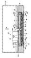
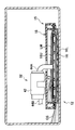
- FIG. 1 shows a schematic configuration of the fuel supply device 12 according to the first embodiment of the present invention.
- the fuel supply device 12 has a fuel tank body 14 in which fuel is accommodated.
- the fuel tank main body 14 is formed, for example, in a substantially box shape, and a sub tank 15 having a fuel filter 16 and a storage member 18 is disposed therein as shown in FIG.
- the fuel filter 16 has a plurality of filter cloths (two sheets of an upper filter cloth 16U and a lower filter cloth 16L in the present embodiment) arranged one above the other.
- the upper filter cloth 16U and In the lower filter cloth 16L, weld portions 16C, which are an example of the joint portion of the present invention, are set on the respective outer peripheral portions.
- the upper surface filter cloth 16U and the lower surface filter cloth 16L are partially overlapped and welded.
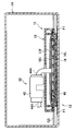
- a gap member 52 is disposed between the upper filter cloth 16U and the lower filter cloth 16L.
- the upper filter cloth 16U and the lower filter cloth 16L allow fuel to pass from the outside to the inside of the bag-like fuel filter 16. Further, by restricting the passage of foreign matters in the fuel during the passage of the fuel, a material (for example, woven cloth, etc.) having an action of removing the foreign matters from the fuel and preventing the foreign matters from flowing into the fuel filter 16. Nonwoven fabric, porous resin, mesh member, etc.). Further, the upper filter cloth 16U and the lower filter cloth 16L are formed in the same shape (for example, a polygonal shape such as a square shape, a circular shape, an elliptical shape, etc.) in plan view (viewed in the direction of arrow A). Has been.
- the fuel filter 16 can store the fuel that has passed through the upper filter cloth 16U and the lower filter cloth 16L. Further, in a state where at least a part of the fuel filter 16 is immersed in the fuel in the fuel tank main body 14, an oil film LM made of fuel is formed and maintained on the surface of the fuel filter 16.
- the fuel filter 16 (particularly the lower filter cloth 16L) is disposed so as to be substantially parallel to the bottom surface 14B of the fuel tank body 14, and a gap is formed between the fuel filter 16 and the bottom surface 14B. As shown by an arrow F1 in FIG. 1, the fuel can flow into the filter 16 through this gap.
- the upper filter cloth 16U and the lower filter cloth 16L are made of different materials.
- the material of these filter cloths is selected so that the pressure loss of the upper filter cloth 16U is larger than the pressure loss of the lower filter cloth 16L.
- the “pressure loss” here is the difference between the pressure before passing and the pressure after passing when the fuel passes through the upper filter cloth 16U or the lower filter cloth 16L (for example, when the fuel pump main body 42 described later is driven). is there. Therefore, the lower surface filter cloth 16L is relatively easier to pass fuel than the upper surface filter cloth 16U.
- the upper surface filter cloth 16U has a structure in which the total area of the voids of the nonwoven fabric is smaller than that of the lower surface filter cloth 16L.
- the gap member 52 is disposed between the upper surface filter cloth 16U and the lower surface filter cloth 16L in the horizontal direction so as to be parallel to the plurality of horizontal bone pieces 56A arranged in the horizontal direction and orthogonal to the horizontal bone pieces 56A. And a plurality of longitudinal bone pieces 56B parallel to each other. Since these bone fragments are positioned between the upper filter cloth 16U and the lower filter cloth 16L, the upper filter cloth 16U and the lower filter cloth 16L are not in contact with each other in the vertical direction in the portion where the bone fragments exist.
- the above-described space for containing fuel is configured.
- the sub tank 15 has a sub tank upper member 15U located above the fuel filter 16, and a sub tank lower member 15L located below the fuel filter 16.
- Each of the sub-tank upper member 15U and the sub-tank lower member 15L is an example of the “nip piece” in the present invention.
- the sub tank upper member 15U has a vertical wall portion 20 located around the fuel filter 16 in a plan view (viewed in the direction of arrow A in FIG. 1).
- the vertical wall portion 20 is formed in, for example, a flat cylindrical shape. From the upper end of the vertical wall portion 20, the cover plate portion 22 extends in a direction approaching a fuel suction pipe 44A described later (a direction toward the center in plan view).
- an upper sandwiching wall 30U is erected downward from the cover plate portion 22 inside the vertical wall portion 20 when viewed in plan.
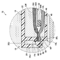
- the upper sandwiching wall 30U is located at a position adjacent to the welded portion 16C when viewed from above and inside the welded portion 16C.
- the upper sandwiching wall 30U sandwiches the upper and lower filter cloths 16U and 16L in the vertical direction between the upper sandwiching wall 30L and the lower sandwiching wall 30L.
- the storage member 18 is configured by the upper sandwiching wall 30U, the cover plate portion 22 inside thereof, and the upper filter cloth 16U of the fuel filter 16. In other words, at least a part (all in the example of FIG. 2) of the bottom of the storage member 18 is configured by the upper filter cloth 16U.
- the storage member 18 can store fuel above the fuel filter 16.
- An inflow hole 24 penetrating the lid plate portion 22 in the thickness direction is formed in the approximate center of the lid plate portion 22.
- a fuel suction pipe 44 ⁇ / b> A is inserted through the center of the inflow hole 24.
- the inner diameter of the inflow hole 24 is larger than the outer diameter of the fuel suction pipe 44A.
- the hole edge of the inflow hole 24 and the fuel suction pipe 44A are not in contact with each other, and fuel can flow into the storage member 18 through the gap 28 as indicated by an arrow F3. Since the inflow hole 24 also serves as an insertion hole for inserting the fuel suction pipe 44A, it is not necessary to form such an insertion hole again, and the structure is simplified.
- the sub tank lower member 15L has a bottom plate portion 46 positioned below the lower filter cloth 16L.
- the bottom plate portion 46 is formed with a plurality of insertion holes 48 penetrating in the thickness direction. As indicated by the arrow F ⁇ b> 1, the fuel GS in the fuel tank body 14 can flow into the fuel filter 16 through the insertion hole 48.
- a flat cylindrical lower sandwiching wall 30L is erected from the periphery of the bottom plate portion 46.
- the lower clamping wall 30L constitutes a clamping member of the present invention.
- the lower sandwiching wall 30L sandwiches the upper filter cloth 16U and the lower filter cloth 16L in the overlapping direction (vertical direction) with the upper sandwiching wall 30U.
- the sandwiching position NP is different from the welded portion 16C.
- the position is set to a position adjacent to the welded portion 16C in plan view (as viewed in the overlapping direction).
- the sandwiching position NP is located inside the welded portion 16C in plan view.
- the fuel tank main body 14 can be stably disposed at a predetermined position (position along the bottom surface 14B).
- an outer ring portion 50 is formed facing outward when viewed in plan.
- the outer ring portion 50 is formed in an annular shape and is shaped to enter the inside of the vertical wall portion 20 of the sub tank upper member 15U.
- a plurality of engaging cylinders 58 are erected upward from a predetermined position of the outer ring portion 50.
- An engagement piece 60 protrudes from the engagement cylinder 58.
- the outer peripheral portion of the fuel filter 16 (the outer portion of the welded portion 16C) is in contact with the inner peripheral surface of the engagement cylinder 58. Thereby, the fuel filter 16 is positioned with respect to the sub tank 15.
- a fuel pump module 32 is provided above the storage member 18.
- the fuel pump module 32 has a fuel pump main body 42.
- the fuel pump main body 42 is supported on the sub tank 15 by the bracket 42B.
- a fuel suction pipe 44 ⁇ / b> A extends downward from one side surface of the fuel pump main body 42.
- the lower end of the fuel suction pipe 44 ⁇ / b> A passes through the bottom wall 38 of the fuel holding member 36 and the upper filter cloth 16 ⁇ / b> U and is opened in the fuel filter 16.
- an upward fuel discharge pipe 44 ⁇ / b> B extends to the outside of the fuel tank main body 14 from the other side surface of the fuel pump main body 42.
- the gap 28 (the gap between the inflow hole 24 and the fuel suction pipe 44A).
- the fuel that has flowed in is stored in the storage member 18. In this state, fuel is also present in the fuel filter 16.
- the fuel in the fuel filter 16 is sent to the outside (engine or the like) through the fuel suction pipe 44A and the fuel discharge pipe 44B as indicated by an arrow F0.
- Fuel can flow into the fuel filter 16 through the upper filter cloth 16U (see arrow F2) and the lower filter cloth 16L (see arrow F1). Further, the fuel in the fuel tank main body 14 flows into the storage member 18 through the gap 28 as indicated by an arrow F3.
- an oil film LM made of fuel is formed on the surface of the fuel filter 16. Is formed and maintained.
- the fuel filter 16 since the fuel filter 16 is disposed along the bottom surface 14B of the fuel tank main body 14, it is more reliable that the fuel in the fuel tank main body 14 is in contact with the fuel filter 16 (lower filter cloth 16L). Can be maintained.
- the upper filter cloth 16U and the lower filter cloth 16L are welded by the welding portion 16C, and the two are in close contact with each other. Therefore, even if the fuel GS is not in contact with the upper surface filter cloth 16U, if the fuel is in contact with the lower surface filter cloth 16L, the fuel oil film LM is formed and maintained on the surface of the fuel filter 16. Yes.
- the liquid level of the fuel GS in the fuel tank body 14 may be inclined during acceleration / deceleration of the vehicle, turning, or the like.
- the upper part of the fuel filter 16 is exposed in the gas in the fuel tank main body 14, but the lower part of the liquid level is immersed in the fuel.
- the oil film LM on the surface is maintained.
- the fuel stored in the storage member 18 is the fuel filter 16 (upper filter cloth 16U). If it is in contact with a part of the fuel, an oil film LM made of fuel is formed and maintained on the surface of the fuel filter 16.
- the energy required for sending the fuel has a relationship of (gas suction from the gas phase)> (fuel suction from the liquid phase) due to the surface tension of the oil film, only the fuel is sucked into the fuel filter 16. Is done. In these states, the fuel in the fuel filter 16 can be sent to the outside by driving the fuel pump module 32.
- the sub tank 15 is configured to include a sub tank upper member 15U and a sub tank lower member 15L, and the upper filter cloth 16U and the lower filter cloth 16L are formed by the upper sandwich wall 30U and the lower sandwich wall 30L. It is sandwiched.
- the shape of the fuel filter 16 can be stably maintained and can be stably disposed at a predetermined position in the fuel tank body 14.
- the sandwiching position NP that sandwiches the upper filter cloth 16U and the lower filter cloth 16L between the upper sandwiching wall 30U and the lower sandwiching wall 30L is a position different from the welding portion 16C. ing.
- a load of the sub tank 15 or other external force acts on the sandwiching position NP due to disturbance caused by vehicle vibration or the like.
- the external force does not act on the welded portion 16C.
- the welding strength of the welding part 16C can be maintained.
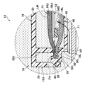
- the sandwiching position NP is located on the inner side of the welded portion 16C when viewed in plan. Even if the forces FA and FB in the direction of separating them from each other act on the upper surface filter cloth 16U and the lower surface filter cloth 16L, the forces FA and FB do not act on the welded portion 16C because there is the sandwiching position NP. That is, the welding strength of the welded portion 16C can be maintained against the force that separates the upper filter cloth 16U and the lower filter cloth 16L.
- the sandwiching position NP and the welded portion 16C are adjacent to each other when viewed in plan.
- an arrow F4 in FIG. 3 even if the fuel GS in the fuel filter 16 attempts to permeate between the upper filter cloth 16U and the lower filter cloth 16L, the upper filter cloth 16U and the lower filter cloth 16L at the sandwiching position NP.
- the air gap is small, and the fuel permeability is low. Therefore, permeation of the fuel GS is suppressed at the sandwiching position NP.
- the gap between the upper surface filter cloth 16U and the lower surface filter cloth 16L is small.
- FIG. 6 shows an enlarged view of the fuel supply device 72 according to a modification of the first embodiment of the present invention in the vicinity of the welded portion 16C and the sandwiching position NP.
- the sandwiching position NP where the upper sandwiching wall 30U and the lower sandwiching wall 30L sandwich the upper filter cloth 16U and the lower filter cloth 16L has the upper filter cloth 16U and the upper filter cloth 16U.
- the outer peripheral portion of the lower filter cloth 16L is used. And the welding part 16C is set in the inner side. Even in such a structure, since the sandwiching position NP and the welded portion 16C are adjacent to each other when seen in a plan view, the permeation of the fuel GS from within the fuel filter 16 is suppressed at the welded portion 16C. It is suppressed at the sandwiching position NP.
- the sandwiching position NP is located on the outer peripheral portion of the upper surface filter cloth 16U and the lower surface filter cloth 16L. Therefore, even when the vertical wall portion 20 of the sub-tank upper member 15U and the welded portion 16C are relatively close to each other due to disturbance or the like, the force acting on the welded portion 16C from the vertical wall portion 20 is relieved by the vertical wall portion 20. The For this reason, the welding strength of the welding part 16C can be maintained.
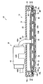
- FIG. 7 shows a sub tank 85 constituting the fuel supply device 82 of the second embodiment of the present invention.
- the overall configuration of the fuel supply device 82 is the same as that of the fuel supply device 12 of the first embodiment, and is not shown.
- the same components and members as those of the sub tank 15 of the first embodiment are denoted by the same reference numerals, and detailed description thereof is omitted.
- the sub tank 85 of the second embodiment includes the sub tank upper member 85U and the sub tank lower member 85L having substantially the same shape as the sub tank upper member 15U and the sub tank lower member 15L according to the first embodiment.
- 85U and the sub tank lower member 85L are connected by a hinge portion 85H provided on a part of the outer periphery thereof.
- the sub tank lower member 85L is rotated with respect to the sub tank upper member 85U by the hinge portion 85H as indicated by an arrow R1.
- the engagement piece 60 of the sub tank lower member 15L engages with the engagement hole 62 of the sub tank upper member 15U (so-called snap fit or the like).
- the hinge portion 85H is a thin-walled hinge.
- the sub tank upper member 15U and the sub tank lower member 15L are integrated by the hinge portion 85H.
- the fuel supply device 82 according to the second embodiment configured as described above also has the same operational effects as the fuel supply device 12 according to the first embodiment.
- the fuel supply device 82 of the second embodiment since the sub tank upper member 85U and the sub tank lower member 85L are integrated, the number of parts is reduced as compared with a separate structure. If the sub tank upper member 85U and the sub tank lower member 85L are integrally formed, the assembly process is reduced.
- the pressure loss of the upper filter cloth 16U and the pressure loss of the lower filter cloth 16L may be the same.
- the pressure loss of the lower filter cloth 16L is the upper filter cloth. It is set lower (smaller) than the pressure loss of 16U. Thereby, first, more fuel passes from the lower surface filter cloth 16L and flows into the fuel filter 16, so that the state in which the fuel is stored in the storage member 18 can be maintained.
- the “joining portion” of the present invention is not limited to the welded portion 16C described above.
- a plurality of filter media (the upper filter cloth 16U and the lower filter cloth 16L) may be joined so as to be continuous.
- a plurality of filter media are continuous by bonding, stitching, or the like to form a bag-like fuel filter as a whole is included.
- the bonding strength of the bonded portion and the stitched portion can be maintained if the sandwiching position NP is set to a position different from the bonded portion even for the bonded portion by bonding or stitching.
- the fuel filter of the present invention is composed of two filter cloths, the upper filter cloth 16U and the lower filter cloth 16L, but is composed of three or more filter cloths (filter media). May be. Even when three or more filter media are used, a bag-like fuel filter can be formed as a whole by joining the filter media at the joint. Then, a sandwiching position may be set at a position different from the joint, and the filter medium constituting the fuel filter may be sandwiched.
- the upper sandwiching wall 30U and the lower sandwiching wall provided in the above-described sub tank upper members 15U and 85U (sandwiching pieces) and the sub tank lower members 15L and 85L (sandwiching pieces). It is not limited to 30L.
- the fuel filter 16 a plurality of filter media
- it may be a member that exhibits the effects of maintaining the shape of the fuel filter 16 and ensuring the strength. Good.
- the upper sandwiching wall 30U and the lower sandwiching wall 30L are both formed in a cylindrical shape, and the sandwiching position NP is annular.
- the “clamping position” of the present invention does not need to be set in an annular shape with respect to the filter medium (upper surface filter cloth 16U and lower surface filter cloth 16L).
- the shape set discontinuously in the direction along the outer periphery of 16 may be used.
- the relationship between the storage member 18 and the fuel suction pipe 44A is not limited to the above-described relationship.
- the fuel suction pipe 44 ⁇ / b> A may be configured to penetrate the lid plate portion 22 at a position different from the inflow hole 24 of the lid plate portion 22.
- the storage member 18 may not cover a part of the fuel filter 16 (a part of the fuel filter 16 protrudes outward from the storage member 18 when viewed from above). In this case, if the fuel suction pipe 44 ⁇ / b> A is connected to the protruding portion of the fuel filter 16 (outside the storage member 18), a structure that does not penetrate the cover plate portion 22 can be achieved.
- the fuel pump module 32 having the fuel pump main body 42 is described above.
- the fuel pump main body 42 is not necessary.
Landscapes
- Engineering & Computer Science (AREA)
- Chemical & Material Sciences (AREA)
- Combustion & Propulsion (AREA)
- Mechanical Engineering (AREA)
- General Engineering & Computer Science (AREA)
- Chemical Kinetics & Catalysis (AREA)
- Cooling, Air Intake And Gas Exhaust, And Fuel Tank Arrangements In Propulsion Units (AREA)
Abstract
Description
Claims (7)
- 燃料を収容する燃料タンク本体と、
前記燃料タンク本体内に備えられ、前記燃料の通過を許容し該燃料中の異物の通過を制限する複数枚の濾材を接合部により重ね合わせて接合し、全体で袋状に形成された燃料フィルタと、
前記複数枚の濾材を前記接合部と異なる挟込位置で挟み込む挟込部材と、
前記複数枚の濾材の間に配置され該濾材の間隔を維持する間隔維持部材と、
前記燃料フィルタ内から燃料を前記燃料タンク本体の外部に送出するための送出手段と、
を有する燃料供給装置。 - 前記燃料フィルタが、上下に配置された複数枚の前記濾材を用いこれら濾材の外周部分に前記接合部を設定して接合されることで偏平な袋状に形成され、
前記挟込部材が、前記複数枚の濾材を前記挟込位置で上下方向に挟み込んでいる請求項1に記載の燃料供給装置。 - 前記間隔維持部材が、前記複数枚の濾材の間で上下方向の前記間隔を維持するように配置されている請求項2に記載の燃料供給装置。
- 前記接合部と前記挟込位置とが前記複数枚の濾材の重ね合わせ方向に見て隣接している請求項1~請求項3のいずれか1項に記載の燃料供給装置。
- 前記挟込位置が、前記接合部の内側に位置している請求項1~請求項4のいずれか1項に記載の燃料供給装置。
- 前記接合部が、前記挟込位置の内側に位置している請求項1~請求項4のいずれか1項に記載の燃料供給装置。
- 前記挟込部材が、
ヒンジ部によって互いに回転可能に連結された2つの挟込片と、
前記2つの挟込片を前記複数の濾材を挟み込んだ状態に維持する挟込維持部材と、
を有する請求項1~請求項6のいずれか1項に記載の燃料供給装置。
Priority Applications (4)
| Application Number | Priority Date | Filing Date | Title |
|---|---|---|---|
| US14/123,119 US9441586B2 (en) | 2011-06-02 | 2012-05-17 | Fuel supply device |
| DE112012002339.0T DE112012002339B4 (de) | 2011-06-02 | 2012-05-17 | Kraftstoffzufuhrvorrichtung |
| CN201280026770.2A CN103620206B (zh) | 2011-06-02 | 2012-05-17 | 燃料供给装置 |
| US14/979,036 US9567955B2 (en) | 2011-06-02 | 2015-12-22 | Fuel supply device |
Applications Claiming Priority (2)
| Application Number | Priority Date | Filing Date | Title |
|---|---|---|---|
| JP2011124460A JP5893854B2 (ja) | 2011-06-02 | 2011-06-02 | 燃料供給装置 |
| JP2011-124460 | 2011-06-02 |
Related Child Applications (2)
| Application Number | Title | Priority Date | Filing Date |
|---|---|---|---|
| US14/123,119 A-371-Of-International US9441586B2 (en) | 2011-06-02 | 2012-05-17 | Fuel supply device |
| US14/979,036 Continuation US9567955B2 (en) | 2011-06-02 | 2015-12-22 | Fuel supply device |
Publications (1)
| Publication Number | Publication Date |
|---|---|
| WO2012165165A1 true WO2012165165A1 (ja) | 2012-12-06 |
Family
ID=47259028
Family Applications (1)
| Application Number | Title | Priority Date | Filing Date |
|---|---|---|---|
| PCT/JP2012/062672 Ceased WO2012165165A1 (ja) | 2011-06-02 | 2012-05-17 | 燃料供給装置 |
Country Status (5)
| Country | Link |
|---|---|
| US (2) | US9441586B2 (ja) |
| JP (1) | JP5893854B2 (ja) |
| CN (2) | CN103620206B (ja) |
| DE (1) | DE112012002339B4 (ja) |
| WO (1) | WO2012165165A1 (ja) |
Cited By (2)
| Publication number | Priority date | Publication date | Assignee | Title |
|---|---|---|---|---|
| WO2015078894A1 (en) * | 2013-11-28 | 2015-06-04 | Emitec Gesellschaft Für Emissionstechnologie Mbh | Liquid purification element |
| JP2020063672A (ja) * | 2018-10-15 | 2020-04-23 | 愛三工業株式会社 | 燃料タンク用サブタンク |
Families Citing this family (12)
| Publication number | Priority date | Publication date | Assignee | Title |
|---|---|---|---|---|
| JP5571366B2 (ja) * | 2009-12-04 | 2014-08-13 | 愛三工業株式会社 | フィルタ装置 |
| DE102011112325A1 (de) * | 2011-09-02 | 2013-03-07 | Emitec Gesellschaft Für Emissionstechnologie Mbh | Vorrichtung zur Bereitstellung von flüssigem Reduktionsmittel |
| KR101340914B1 (ko) * | 2013-05-23 | 2013-12-13 | 주식회사 코아비스 | 스트레이너 및 이를 포함하는 연료펌프모듈 |
| JP2016160890A (ja) * | 2015-03-04 | 2016-09-05 | 愛三工業株式会社 | 燃料供給装置 |
| JP6265200B2 (ja) * | 2015-07-29 | 2018-01-24 | 株式会社デンソー | サクションフィルタ及び燃料供給装置 |
| JP6380364B2 (ja) * | 2015-12-17 | 2018-08-29 | 株式会社デンソー | 燃料ポンプ及び燃料ポンプモジュール |
| DE112017000895B4 (de) * | 2016-02-19 | 2022-03-10 | Aisan Kogyo Kabushiki Kaisha | Kraftstoffzufuhrvorrichtung mit Siebbauteil |
| CN109416006B (zh) * | 2016-07-05 | 2021-02-02 | 京三电机株式会社 | 水分凝集器、燃料过滤装置、以及水分凝集器的制造方法 |
| DE102017212768A1 (de) * | 2017-07-25 | 2019-01-31 | Robert Bosch Gmbh | Flüssigkeitsfilter und Tankfiltersystem mit einem Flüssigkeitsfilter |
| JP2020016158A (ja) * | 2018-07-23 | 2020-01-30 | 京三電機株式会社 | 燃料供給装置 |
| KR102178858B1 (ko) * | 2019-09-25 | 2020-11-13 | 주식회사 코아비스 | 연료펌프용 스트레이너 |
| US12320087B2 (en) * | 2021-07-14 | 2025-06-03 | The United States Of America As Represented By The Secretary Of Agriculture | Submerged liquid intake strainers |
Citations (3)
| Publication number | Priority date | Publication date | Assignee | Title |
|---|---|---|---|---|
| JPS59142016U (ja) * | 1983-03-12 | 1984-09-22 | 日産自動車株式会社 | 燃料ポンプのストレ−ナ |
| JPH06317286A (ja) * | 1993-05-06 | 1994-11-15 | Aisan Ind Co Ltd | 電動フューエルポンプ用フィルタ |
| JP2005030351A (ja) * | 2003-07-10 | 2005-02-03 | Nifco Inc | 燃料用フィルタ装置 |
Family Cites Families (22)
| Publication number | Priority date | Publication date | Assignee | Title |
|---|---|---|---|---|
| JPS59142016A (ja) * | 1983-01-28 | 1984-08-15 | Yoshida Shokai:Kk | 押圧盤 |
| JPH0420487Y2 (ja) * | 1987-03-12 | 1992-05-11 | ||
| US5607578A (en) | 1993-05-06 | 1997-03-04 | Aisan Kogyo Kabushiki Kaisha | Filter system for an in-tank fuel pump |
| JP2925907B2 (ja) | 1993-12-27 | 1999-07-28 | 本田技研工業株式会社 | フィルタ装置 |
| JP3453686B2 (ja) * | 1994-03-29 | 2003-10-06 | 株式会社パイオラックス | 燃料タンク用フィルター |
| US5558246A (en) * | 1995-06-12 | 1996-09-24 | Ross, Jr.; George S. | Bottled gas tank holder |
| US5647328A (en) * | 1995-06-30 | 1997-07-15 | Walbro Corporation | In-tank fuel pump and reservoir |
| EP0787519A2 (en) * | 1996-02-01 | 1997-08-06 | Toyo Roki Seizo Kabushikikaisha | Filter and filter medium unit for use therein |
| JPH10184345A (ja) | 1996-12-24 | 1998-07-14 | Nissan Motor Co Ltd | エンジンの排気浄化装置 |
| JP3387784B2 (ja) * | 1997-07-25 | 2003-03-17 | 京三電機株式会社 | 燃料フイルタにおける濾部の取り付け構造 |
| US6138686A (en) * | 1998-10-28 | 2000-10-31 | Yoshida Industry Co. Ltd. | Cosmetic case |
| JP2002028408A (ja) * | 2000-07-18 | 2002-01-29 | Kyosan Denki Co Ltd | 濾過器 |
| DE10136437A1 (de) * | 2001-07-26 | 2003-02-13 | Bosch Gmbh Robert | Kraftstoffversorgungseinrichtung für ein Kraftfahrzeug |
| JP3932551B2 (ja) * | 2002-10-03 | 2007-06-20 | 株式会社デンソー | 燃料供給装置 |
| JP4280601B2 (ja) | 2003-10-24 | 2009-06-17 | 株式会社ニフコ | フューエルフィルタ装置 |
| JP2005201214A (ja) * | 2004-01-19 | 2005-07-28 | Mitsubishi Electric Corp | 燃料供給装置 |
| JP2008174074A (ja) | 2007-01-18 | 2008-07-31 | Fts:Kk | 燃料タンク |
| JP4400679B2 (ja) * | 2007-07-23 | 2010-01-20 | 株式会社デンソー | 燃料供給装置 |
| JP5257130B2 (ja) | 2009-02-23 | 2013-08-07 | 京三電機株式会社 | サクションフィルタ |
| US8490682B2 (en) | 2009-05-20 | 2013-07-23 | Kuss Filtration Inc. | Suction filter design for fluid thawing |
| CN102052217B (zh) * | 2009-11-05 | 2013-03-06 | 三菱电机株式会社 | 燃料供给装置 |
| JP2011163198A (ja) * | 2010-02-09 | 2011-08-25 | Aisan Industry Co Ltd | 燃料フィルタ |
-
2011
- 2011-06-02 JP JP2011124460A patent/JP5893854B2/ja active Active
-
2012
- 2012-05-17 US US14/123,119 patent/US9441586B2/en active Active
- 2012-05-17 WO PCT/JP2012/062672 patent/WO2012165165A1/ja not_active Ceased
- 2012-05-17 CN CN201280026770.2A patent/CN103620206B/zh active Active
- 2012-05-17 DE DE112012002339.0T patent/DE112012002339B4/de active Active
- 2012-05-17 CN CN201510934921.XA patent/CN105402063B/zh active Active
-
2015
- 2015-12-22 US US14/979,036 patent/US9567955B2/en active Active
Patent Citations (3)
| Publication number | Priority date | Publication date | Assignee | Title |
|---|---|---|---|---|
| JPS59142016U (ja) * | 1983-03-12 | 1984-09-22 | 日産自動車株式会社 | 燃料ポンプのストレ−ナ |
| JPH06317286A (ja) * | 1993-05-06 | 1994-11-15 | Aisan Ind Co Ltd | 電動フューエルポンプ用フィルタ |
| JP2005030351A (ja) * | 2003-07-10 | 2005-02-03 | Nifco Inc | 燃料用フィルタ装置 |
Cited By (7)
| Publication number | Priority date | Publication date | Assignee | Title |
|---|---|---|---|---|
| WO2015078894A1 (en) * | 2013-11-28 | 2015-06-04 | Emitec Gesellschaft Für Emissionstechnologie Mbh | Liquid purification element |
| CN105792909A (zh) * | 2013-11-28 | 2016-07-20 | 大陆汽车有限责任公司 | 液体净化单元 |
| CN105792909B (zh) * | 2013-11-28 | 2018-03-02 | 大陆汽车有限责任公司 | 液体净化单元 |
| RU2674823C1 (ru) * | 2013-11-28 | 2018-12-14 | Континенталь Аутомотив ГмбХ | Элемент для очистки жидкостей |
| US10392995B2 (en) | 2013-11-28 | 2019-08-27 | Continental Automotive Gmbh | Liquid purification element |
| JP2020063672A (ja) * | 2018-10-15 | 2020-04-23 | 愛三工業株式会社 | 燃料タンク用サブタンク |
| JP7046778B2 (ja) | 2018-10-15 | 2022-04-04 | 愛三工業株式会社 | 燃料タンク用サブタンク |
Also Published As
| Publication number | Publication date |
|---|---|
| CN105402063B (zh) | 2018-04-10 |
| DE112012002339B4 (de) | 2017-11-23 |
| US20160108872A1 (en) | 2016-04-21 |
| US20140096849A1 (en) | 2014-04-10 |
| CN103620206A (zh) | 2014-03-05 |
| JP5893854B2 (ja) | 2016-03-23 |
| CN105402063A (zh) | 2016-03-16 |
| US9567955B2 (en) | 2017-02-14 |
| JP2012251481A (ja) | 2012-12-20 |
| CN103620206B (zh) | 2016-02-10 |
| US9441586B2 (en) | 2016-09-13 |
| DE112012002339T5 (de) | 2014-02-20 |
Similar Documents
| Publication | Publication Date | Title |
|---|---|---|
| JP5893854B2 (ja) | 燃料供給装置 | |
| US7901572B2 (en) | Fuel filter apparatus | |
| JP5768807B2 (ja) | フィルタ装置 | |
| US10794343B2 (en) | Suction filter and fuel supply device | |
| CN107850018B (zh) | 吸滤器及燃料供给装置 | |
| CN104081036B (zh) | 燃料供给装置 | |
| CN101980765A (zh) | 膜分离装置及膜盒 | |
| JP6067799B2 (ja) | サブタンク | |
| JP2012067736A (ja) | 燃料供給装置 | |
| JP5615159B2 (ja) | 燃料供給装置 | |
| JP6055046B2 (ja) | 燃料供給装置 | |
| US10646802B2 (en) | Suction filter and fuel supply device | |
| JP2012036792A (ja) | 燃料供給装置 | |
| JP2012087728A (ja) | 燃料フィルター用ケース及び燃料フィルター装置 | |
| JP5508635B2 (ja) | 燃料供給装置 | |
| JP2009165965A (ja) | 燃料用フィルタ装置 | |
| JP2013044269A (ja) | 燃料供給装置 | |
| JP5724784B2 (ja) | 燃料供給装置 | |
| JP2005075059A (ja) | 濾過器 | |
| WO2016114132A1 (ja) | サクションフィルタ及び燃料供給装置 | |
| KR20150076727A (ko) | 연료펌프모듈용 접이식 필터장치 | |
| JP2013050051A (ja) | 燃料供給装置 | |
| CN112049745A (zh) | 用于箱内燃料泵的燃料过滤器 |
Legal Events
| Date | Code | Title | Description |
|---|---|---|---|
| 121 | Ep: the epo has been informed by wipo that ep was designated in this application |
Ref document number: 12793038 Country of ref document: EP Kind code of ref document: A1 |
|
| WWE | Wipo information: entry into national phase |
Ref document number: 14123119 Country of ref document: US |
|
| WWE | Wipo information: entry into national phase |
Ref document number: 112012002339 Country of ref document: DE Ref document number: 1120120023390 Country of ref document: DE |
|
| 122 | Ep: pct application non-entry in european phase |
Ref document number: 12793038 Country of ref document: EP Kind code of ref document: A1 |