WO2012165150A1 - 熱線遮蔽フィルム、これを用いた熱線遮蔽ウィンドウ - Google Patents
熱線遮蔽フィルム、これを用いた熱線遮蔽ウィンドウ Download PDFInfo
- Publication number
- WO2012165150A1 WO2012165150A1 PCT/JP2012/062599 JP2012062599W WO2012165150A1 WO 2012165150 A1 WO2012165150 A1 WO 2012165150A1 JP 2012062599 W JP2012062599 W JP 2012062599W WO 2012165150 A1 WO2012165150 A1 WO 2012165150A1
- Authority
- WO
- WIPO (PCT)
- Prior art keywords
- heat ray
- ray shielding
- reflective layer
- shielding film
- ray reflective
- Prior art date
- Legal status (The legal status is an assumption and is not a legal conclusion. Google has not performed a legal analysis and makes no representation as to the accuracy of the status listed.)
- Ceased
Links
Images


Classifications
-
- G—PHYSICS
- G02—OPTICS
- G02B—OPTICAL ELEMENTS, SYSTEMS OR APPARATUS
- G02B5/00—Optical elements other than lenses
- G02B5/20—Filters
- G02B5/26—Reflecting filters
Definitions
- the present invention relates to a heat ray shielding film having heat ray shielding property or heat ray reflection property, and a heat ray shielding window using the heat ray shielding film.
- these windows have a function of shielding infrared rays (heat rays) in sunlight, The function to reflect and insulate the heat rays radiated from is required.
- a thin film of a transparent conductive film such as indium tin oxide (ITO) or tin oxide (ATO) is formed into a dry film, and a noble metal film / metal oxide film mainly composed of a metal oxide film / Ag film is laminated.
- ITO indium tin oxide
- ATO tin oxide
- a heat ray shielding glass Patent Document 1 on which a heat ray shielding film (also referred to as a Low-E film) is formed has been developed and put to practical use.
- the Low-E film has a function (heat insulating property) of transmitting near-infrared rays of sunlight having a relatively short wavelength and shielding mid-infrared rays and far-infrared rays.
- Such heat ray-shielding glass (particularly, the one having the Low-E film formed thereon) should be arranged so as to face another glass plate with a predetermined distance (air layer) to form a multi-layer glass. And what improved the heat insulation is also developed (patent document 2). Thereby, the energy consumption by air conditioning can be further reduced.
- the Low-E film is formed by a vacuum film formation method such as a sputtering method, a large-sized apparatus is required, and the manufacturing cost of the heat ray shielding glass using this becomes high. Further, the metal film is easily corroded, and there is a problem that the appearance characteristics are deteriorated by long-term use.
- a heat ray shielding glass having a heat ray reflective layer made of a conductive polymer has also been developed (Patent Document 3). Since the conductive polymer is an organic polymer, a layer can be formed by a coating method or the like, and can be manufactured at low cost. In the case of such a heat ray reflective layer made of a conductive polymer, it is necessary to increase the free electron density in order to obtain high heat ray reflectivity.
- an object of the present invention is to provide a heat ray shielding film that can be produced at low cost, has excellent heat ray reflectivity, and is excellent in visible light transmittance.
- an object of the present invention is to provide a heat ray shielding window using this heat ray shielding film.
- a layer containing metal nanofibers has an excellent heat ray reflecting function, and have led to the present invention. That is, the above object is achieved by a heat ray shielding film comprising a transparent film and a heat ray reflective layer provided on the surface thereof, wherein the heat ray reflective layer comprises metal nanofibers. .
- Metal nanofibers are submicron-level fine metal fibers also called metal nanowires or metal nanorods. Since the layer containing metal nanofibers has high transparency with high heat ray reflectivity (also referred to as low radiation), according to the present invention, a heat ray shielding film having excellent heat ray reflectivity and excellent visible light permeability is obtained. Can do.
- the heat ray shielding film of the present invention are as follows.
- the metal nanofiber is made of silver.
- the heat ray reflective layer is a coating layer containing a binder resin. It can be set as the heat ray shielding film which can be manufactured at low cost.
- the heat ray reflective layer further contains a conductive polymer. Thereby, it can be set as the heat ray shielding film which was further excellent in heat ray reflectivity, and excellent in the visible light transmittance.
- the heat ray reflective layer includes a first heat ray reflective layer containing metal nanofibers and a second heat ray reflective layer made of a conductive polymer. Usually, the second heat ray reflective layer does not contain metal nanofibers.
- the first heat ray reflective layer is formed on the outermost layer. Heat ray reflectivity can be exhibited more effectively.
- the conductive polymer is represented by the following formula (I): (Wherein R 1 and R 2 each independently represent a hydrogen atom or an alkyl group having 1 to 4 carbon atoms, or R 1 and R 2 may be bonded to each other and optionally substituted)
- a polythiophene derivative comprising a repeating unit represented by the formula (1): an alkylene group having 1 to 4 carbon atoms, and n represents an integer of 50 to 1000. Since the above polythiophene derivative has high conductivity, it is suitable as a conductive polymer to be contained in the heat ray reflective layer in the present invention.
- the total thickness of the heat ray reflective layer is 10 to 3000 nm.
- a heat ray shielding window in which the heat ray shielding film of the present invention is adhered to a transparent substrate on the surface opposite to the surface on which the heat ray reflective layer is provided.
- the heat ray shielding window which is excellent in heat insulation, is excellent in visible light permeability, and can be manufactured at low cost.
- the object is to provide a laminate in which the heat ray shielding film of the present invention is bonded to a transparent substrate on the surface opposite to the surface on which the heat ray reflective layer is provided, and another transparent substrate, with a gap.
- the heat ray reflective layer is disposed so as to face the another transparent substrate, and a hollow layer is formed by a gap between the heat ray reflective layer and the heat ray shielding window.
- a window having a hollow layer in the gap between two transparent substrates is generally called multi-layer glass.
- the heat ray reflective layer of the heat ray shielding film of the present invention can be protected from moisture such as rainwater, condensation, moisture, etc., and the heat insulation performance is maintained for a long time. can do.
- the said hollow layer is formed when the said laminated body and said another transparent substrate are arrange
- the heat ray reflective layer of the heat ray shielding film contains metal nanofibers, the heat ray such as heating that is radiated from the room is not reflected and escaped, and the heat from outside air is not taken into the room. It can be set as the heat ray shielding film excellent in visible-light transmittance. Moreover, since the heat ray reflective layer containing metal nanofibers can be formed with a binder resin by a low cost coating method, the heat ray shielding film of the present invention can be produced at a low cost.
- the heat ray shielding window of the present invention uses the heat ray shielding film of the present invention, it can be said that the heat ray shielding window is an inexpensive heat ray shielding window having excellent heat insulation and high visible light permeability.
- FIG. 1 is a schematic sectional view showing an example of the heat ray shielding film of the present invention.
- FIG. 2 is a schematic sectional view showing another example of the heat ray shielding film of the present invention.
- FIG. 3 is a schematic sectional view showing an example of the heat ray shielding window of the present invention.
- FIG. 4 is a schematic sectional view showing another example of the heat ray shielding window of the present invention.
- FIG. 1 is a schematic sectional view showing an example of the heat ray shielding film of the present invention.
- the heat ray reflective layer 14 only needs to contain metal nanofibers, and may be formed in any manner. Since a layer can be formed at low cost, a coating layer formed by coating a coating liquid containing metal nanofibers and a binder resin on the surface of the transparent film 13 is preferable.
- the heat ray shielding film 10 of the present invention has the heat ray reflective layer 14 containing metal nanofibers, thereby effectively reflecting the heat ray, that is, the effect of suppressing the emissivity by effectively reflecting infrared rays (low emissivity). Can be demonstrated. Moreover, since the metal nanofibers have high transparency with respect to wavelengths in the visible light region, the heat ray reflective layer 14 has high visible light transparency.
- Metal nanofibers can be prepared by a conventionally known technique.
- silver nanofibers can be synthesized by liquid phase reduction of silver salts such as silver nitrate in the presence of polyols such as ethylene glycol and poly (vinyl pyrrolidone).
- the heat ray reflective layer 14 may contain the above-described binder resin and other materials as long as the radiation suppressing effect of the metal nanofibers is not hindered.
- conductive polymers are particularly preferable. This is because the conductive polymer also effectively blocks infrared rays and exhibits heat insulation. This is thought to be because the plasma absorption wavelength due to free electrons of the conductive polymer is shorter than the radiation of an object near the ground temperature, and reflects electromagnetic waves having a wavelength higher than the plasma absorption wavelength.
- the low radiation property of the heat ray reflective layer 14 can be further enhanced without reducing the visible light transmittance. Details of the conductive polymer will be described later.
- the layer thickness of the heat ray reflective layer 14 is preferably 10 to 3000 nm, more preferably 20 to 1000 nm, and particularly preferably 30 to 500 nm.
- the heat ray shielding film 10 of the present invention may have another layer other than the heat ray reflective layer 14.
- the heat ray reflective layer 14 is preferably formed on the outermost layer of the heat ray shielding film 10 as shown in FIG. 1, but is conductive within a range that does not hinder the radiation suppressing effect of the metal nanofibers ( A metal) thin film or a thin film of an organic resin having no conductivity may be formed on the heat ray reflective layer 14.
- another heat ray reflective layer made of the above-described conductive polymer may be formed.
- FIG. 2 is a schematic cross-sectional view showing another example of the heat ray shielding film of the present invention.
- the heat ray shielding film 20 shown in FIG. 2 includes a transparent film 23 (transparent plastic film), a second heat ray reflective layer 25 made of a conductive polymer formed on the surface thereof, and metal nanofibers formed on the surface thereof. It is comprised from the 1st heat ray reflective layer 24 containing.
- the second heat ray reflective layer 25 made of a conductive polymer usually does not contain metal nanofibers.
- the heat ray reflective layer is composed of the first heat ray reflective layer 24 and the second heat ray reflective layer 25, the radiation suppressing effect can be more effectively exhibited.
- the first heat ray reflective layer 24 is formed as the outermost layer, but the first heat ray reflective layer 24 containing metal nanofibers is formed on the surface of the transparent film 23, and the surface has high conductivity.
- a second heat ray reflective layer 25 made of molecules may be formed. It is preferable that the 1st heat ray reflective layer containing metal nanofiber is formed in the outermost layer as shown in FIG. 2 at the point from which a radiation suppression effect is acquired more efficiently.
- the layer thickness of the first heat ray reflective layer is preferably 10 to 3000 nm, more preferably 20 to 500 nm, and particularly preferably 50 to 300 nm.
- the layer thickness of the second heat ray reflective layer is preferably 10 to 3000 nm, more preferably 50 to 2000 nm, and particularly preferably 100 to 1000 nm.
- the total thickness of the heat ray reflective layer is preferably 10 to 3000 nm, more preferably 70 to 2500 nm, and particularly preferably 150 to 1300 nm.
- the conductive polymer that can be included in the heat ray reflective layer is generally an organic polymer having a conjugated double bond in the basic skeleton, specifically, polythiophene, polypyrrole, polyaniline, polyacetylene, polyparaphenylene, Preferable examples include any one kind or a mixture of two or more kinds of conductive polymers selected from polyfuran, polyfluorene, polyphenylene vinylene, derivatives thereof, and copolymers of monomers constituting them. Among these, polythiophene derivatives that are soluble or dispersible in water or other solvents and exhibit high conductivity and transparency are preferable.
- R 1 and R 2 each independently represent a hydrogen atom or an alkyl group having 1 to 4 carbon atoms, or R 1 and R 2 may be bonded to each other and optionally substituted
- a polythiophene derivative containing a repeating unit represented by (forms an alkylene group having 1 to 4 carbon atoms, and n represents an integer of 50 to 1000) is preferable.
- the optionally substituted alkylene group having 1 to 4 carbon atoms formed by bonding R 1 and R 2 to each other is specifically methylene substituted with an alkyl group.
- Groups, groups that form ethylene-1,2 groups, propylene-1,3 groups, butene-1,4 groups optionally substituted with alkyl groups having 1 to 12 carbon atoms or phenyl groups.
- methylene group R 1 and R 2 form by combining to each other, an ethylene-1,2 radical or propylene-1,3 radical It is.
- Particularly preferred polythiophene derivatives include the following formula (II): (Wherein p represents an integer of 50 to 1000), that is, a polythiophene derivative having a poly (3,4-ethylenedioxythiophene) unit.
- the conductive polymer preferably further contains a dopant (electron donor).
- a dopant electron donor
- Preferred examples of the dopant include polystyrene sulfonic acid, polyacrylic acid, polymethacrylic acid, polymaleic acid, and polyvinyl sulfonic acid.
- polystyrene sulfonic acid is preferable.
- the number average molecular weight Mn of the dopant is preferably 1,000 to 2,000,000, particularly preferably 2,000 to 500,000.
- the content of the dopant is usually 20 to 2000 parts by mass, preferably 40 to 200 parts by mass with respect to 100 parts by mass of the conductive polymer.
- a polythiophene derivative of the formula (II) is used as a conductive polymer and polystyrene sulfonic acid is used as a dopant
- 100 to 200 parts by mass of polystyrene sulfonic acid is preferable with respect to 100 parts by mass of polythiophene, and particularly 120 to 180 parts by mass. Part is preferred.
- the heat ray reflective layer of the heat ray shielding film of the present invention can be formed by a conventionally known method.
- an appropriate method such as a bar coater method, a roll coater method, a curtain flow method, a spray method, etc., on the surface of a transparent film (or another layer) with a coating liquid in which metal nanofibers are dispersed in a solvent together with a binder resin can be formed by coating, drying, and curing as required.
- This wet coating method has the advantage that the film can be uniformly formed at high speed at low cost.
- any binder resin can be used as long as the shape of the coating layer can be maintained.
- an ultraviolet curable resin composition or a thermosetting resin composition can be used.
- the ultraviolet curable resin or thermosetting resin include phenol resin, resorcinol resin, urea resin, melamine resin, epoxy resin, acrylic resin, urethane resin, furan resin, silicone resin, polyester resin, and polyvinyl alcohol resin.
- the ultraviolet curable resin can be used as an ultraviolet curable resin composition together with a photopolymerization initiator and the like
- the thermosetting resin can be used as a thermosetting resin composition together with a thermal polymerization initiator and the like.
- Examples of the ultraviolet curable resin (monomer, oligomer) include (meth) acrylate monomers, polyurethane (meth) acrylate, which is a reaction product of a polyol compound, an organic polyisocyanate, and a hydroxyl group-containing (meth) acrylate, and a bisphenol type epoxy resin.
- (Meth) acrylate oligomers such as bisphenol-type epoxy (meth) acrylate, which is a reaction product of (meth) acrylic acid, can be mentioned. These compounds can be used alone or in combination.
- hard polyfunctional monomers such as pentaerythritol tri (meth) acrylate, pentaerythritol penta (meth) acrylate, dipentaerythritol hexa (meth) acrylate, trimethylolpropane tri (meth) acrylate, and the like.
- These ultraviolet curable resins may be used as a thermosetting resin together with a thermal polymerization initiator.
- any compound suitable for the properties of the ultraviolet curable resin can be used.
- acetophenone series such as 1-hydroxycyclohexyl phenyl ketone
- benzoin series such as benzyldimethyl ketal
- benzophenone series such as benzophenone, thioxanthone series, etc.
- 1-hydroxycyclohexyl phenyl ketone manufactured by BASF Japan, Irgacure 184
- the amount of the photopolymerization initiator is generally 0.1 to 10% by mass, preferably 0.1 to 5% by mass, based on the resin composition.
- thermosetting resin examples include organic peroxides and cationic polymerization initiators that are compounds containing a functional group that initiates polymerization by heating. Among them, organic peroxides are preferable. *
- the thermal polymerization initiator can be used alone or in combination of two or more.
- the amount of the thermal polymerization initiator is generally 0.01 to 10% by mass, preferably 0.1 to 5% by mass, based on the resin composition.
- Examples of the solvent for dispersing the metal nanofibers together with the binder resin include water, alcohol, ketones, hydrocarbons such as tetrahydrofuran and cyclohexane, and aromatic solvents such as benzene and toluene.
- the heat ray reflective layer may contain a small amount of an ultraviolet absorber, an infrared absorber, an anti-aging agent, a paint processing aid, a colorant, and the like, if necessary.
- the amount thereof is generally 0.1 to 10% by mass, preferably 0.1 to 5% by mass, based on the resin composition.
- heat rays of the heat ray shielding film of the present invention contains a conductive polymer
- heat rays can be formed by a conventionally known method.
- a coating solution in which a conductive polymer is dissolved or dispersed is applied to the surface of the transparent film (or another layer) using an appropriate method such as a bar coater method, a roll coater method, a curtain flow method, or a spray method. Apply and dry to form.
- Solvents used in the coating liquid include water; alcohols such as methanol, ethanol and propanol; ketones such as acetophenone and methyl ethyl ketone; halogenated hydrocarbons such as carbon tetrachloride and fluorinated hydrocarbons; ethyl acetate and butyl acetate.
- Preferred examples include esters such as tetrahydrofuran, dioxane and diethyl ether; and amides such as N, N-dimethylacetamide, N, N-dimethylformamide and N-methylpyrrolidone.
- water and alcohols are preferable.
- a heat ray reflective layer contains a metal nanofiber and a conductive polymer (when the heat ray reflective layer 14 of FIG. 1 contains a conductive polymer), the layer is formed with a coating solution to which the above-described binder resin is further added. It may be formed, or a layer may be formed by a coating liquid using a conductive polymer as a binder resin.
- the surface of the transparent plastic film may be subjected to adhesion treatment such as corona treatment, plasma treatment, flame treatment, primer layer coating treatment, etc. in order to improve adhesion, such as copolymer polyester resin and polyurethane resin.
- adhesion treatment such as corona treatment, plasma treatment, flame treatment, primer layer coating treatment, etc.
- An easily adhesive layer such as a thermosetting resin may be provided.
- the thickness of the transparent plastic film is generally 1 ⁇ m to 10 mm, preferably 10 to 400 ⁇ m, and particularly preferably 20 to 200 ⁇ m.
- the heat ray shielding film of the present invention may be used in the form of a film, but in general, an adhesive layer is provided and adhered to a transparent substrate such as a glass plate.
- the heat ray shielding window of the present invention is obtained by bonding the heat ray shielding film of the present invention to a transparent substrate such as a glass plate.
- the heat ray shielding window of the present invention will be described below with reference to the drawings.
- FIG. 3 is a schematic sectional view showing an example of the heat ray shielding window of the present invention.
- the heat ray shielding window 30 shown in FIG. 3 is the same as the heat ray shielding film 10 of the present invention described in FIG. 1 (the heat ray reflecting layer 14 containing metal nanofibers is formed on the surface of the transparent film 13). It is the surface opposite to the surface on which is formed, and is bonded to the transparent substrate 31 via the adhesive layer 32.
- the heat ray shielding window of the present invention is a heat ray shielding window that is excellent in heat insulation and visible light transmittance and can be manufactured at low cost.
- the transparent substrate 31 in the present invention is, for example, a glass plate such as green glass, silicate glass, inorganic glass plate, non-colored transparent glass plate, polyethylene terephthalate (PET), polyethylene naphthalate (PEN), polyethylene butyrate, A plastic substrate such as polymethyl methacrylate (PMMA) or polycarbonate may be used.
- a glass plate is preferable in terms of heat resistance, weather resistance, impact resistance, and the like, and the thickness of the glass plate is generally about 2 to 20 mm.
- Copolymer ethylene-methyl (meth) acrylate copolymer, metal ion crosslinked ethylene- (meth) acrylic acid copolymer, partially saponified ethylene-vinyl acetate copolymer, carboxylated ethylene-vinyl acetate copolymer, ethylene- Ethylene copolymers such as (meth) acrylic-maleic anhydride copolymer and ethylene-vinyl acetate- (meth) acrylate copolymer can be used (in addition, “(meth) acryl” means “acrylic or Methacryl ").
- polyvinyl butyral (PVB) resin epoxy resin, phenol resin, silicone resin, polyester resin, urethane resin, rubber adhesive, thermoplastic elastomer such as SEBS and SBS, and the like can also be used.
- PVB polyvinyl butyral
- EVA is preferably used because it exhibits excellent adhesiveness and high transparency.
- an ethylene copolymer When an ethylene copolymer is used for the adhesive layer, it is preferable to further contain an organic peroxide.
- an organic peroxide By crosslinking and curing with an organic peroxide, adjacent layers and a glass plate can be further joined and integrated. Any organic peroxide may be used in combination as long as it decomposes at a temperature of 100 ° C. or higher and generates radicals.
- the organic peroxide is generally selected in consideration of the film formation temperature, the adjustment conditions of the composition, the curing (bonding) temperature, the heat resistance of the adherend, and the storage stability. In particular, those having a decomposition temperature of 70 hours or more with a half-life of 10 hours are preferred.
- organic peroxide examples include 2,5-dimethylhexane-2,5-dihydroperoxide, 2,5-dimethyl-2,5-di (t-butylperoxy) hexane-3-di- t-butyl peroxide, t-butylcumyl peroxide, 2,5-dimethyl-2,5-di (t-butylperoxy) hexane, dicumyl peroxide, ⁇ , ⁇ '-bis (t-butylperoxy) Isopropyl) benzene, n-butyl-4,4-bis (t-butylperoxy) valerate, 1,1-bis (t-butylperoxy) cyclohexane, 1,1-bis (t-butylperoxy) -3 , 3,5-trimethylcyclohexane, t-butyl peroxybenzoate, benzoyl peroxide, t-butyl peroxyacetate, methyl
- the adhesive layer further contains a silane coupling agent as a crosslinking aid or an adhesion improver.
- crosslinking aid examples include polyfunctional compounds such as esters obtained by esterifying a plurality of acrylic acid or methacrylic acid with glycerin, trimethylolpropane, pentaerythritol and the like, triallyl cyanurate, and triallyl isocyanurate.
- silane coupling agents include ⁇ -chloropropylmethoxysilane, vinylethoxysilane, vinyltris ( ⁇ -methoxyethoxy) silane, ⁇ -methacryloxypropyltrimethoxysilane, vinyltriacetoxysilane, ⁇ -glycidoxypropyltrimethoxy Silane, ⁇ -glycidoxypropyltriethoxysilane, ⁇ - (3,4-epoxycyclohexyl) ethyltrimethoxysilane, vinyltrichlorosilane, ⁇ -mercaptopropyltrimethoxysilane, ⁇ -aminopropyltriethoxysilane, N- ⁇ Mention may be made of-(aminoethyl) - ⁇ -aminopropyltrimethoxysilane. These silane coupling agents may be used alone or in combination of two or more. Moreover, it is preferable that content of the said compound is 5 mass parts
- the adhesive resin layer is used to improve or adjust various physical properties (optical properties such as mechanical strength, adhesiveness, and transparency, heat resistance, light resistance, crosslinking speed, etc.), especially to improve mechanical strength and light resistance.
- It preferably contains an acryloxy group-containing compound, a methacryloxy group-containing compound, an epoxy group-containing compound, a plasticizer, and an ultraviolet absorber.
- the ultraviolet absorber include benzophenone compounds, triazine compounds, benzoate compounds, and hindered amine compounds. From the viewpoint of suppressing yellowing, benzophenone compounds are preferred.
- the ultraviolet absorber is preferably used in an amount of 0.01 to 1.5 parts by mass (particularly 0.5 to 1.0 part by mass) with respect to 100 parts by mass of the ethylene copolymer.
- the thickness of the adhesive layer is preferably 100 to 2000 ⁇ m, particularly 400 to 1000 ⁇ m.
- a composition containing an ethylene copolymer and an organic peroxide is formed by ordinary extrusion molding, calendar molding (calendering), or the like.
- a method for obtaining a layered product can be used.
- the composition is preferably mixed by heating and kneading at a temperature of 40 to 90 ° C., particularly 60 to 80 ° C.
- the heating temperature during film formation is preferably a temperature at which the crosslinking agent does not react or hardly reacts.
- the temperature is preferably 40 to 90 ° C, particularly 50 to 80 ° C.
- the adhesive layer may be formed directly on the surface of the transparent plastic film or transparent substrate, or may be formed separately using a film-like adhesive sheet.
- the heat ray shielding film 10 of the present invention and the transparent substrate 31 shown in FIG. 1 are prepared, and the adhesive layer 32 (the heat ray shielding film of the heat ray shielding film described above) is prepared.
- a laminate in which the heat ray shielding film 10 and the transparent substrate 31 are laminated via an adhesive layer formed on the surface opposite to the surface on which the heat ray reflective layer is formed or an adhesive sheet is laminated on the glass plate.
- EVA when used for the adhesive layer 32, it is generally crosslinked at 100 to 150 ° C. (especially around 130 ° C.) for 10 minutes to 1 hour. This is carried out by degassing the laminate, pre-pressing at a temperature of, for example, 80 to 120 ° C., and heat-treating at 100 to 150 ° C. (especially around 130 ° C.) for 10 minutes to 1 hour. Cooling after crosslinking is generally performed at room temperature, and in particular, the faster the cooling, the better.
- FIG. 4 is a schematic sectional view showing another example of the heat ray shielding window of the present invention.
- the heat ray shielding window 50 shown in FIG. 4 has the heat ray shielding film 10 of the present invention (the heat ray reflective layer 14 containing metal nanofibers is formed on the surface of the transparent film 13) on one surface of the transparent substrate 41.
- the laminated body 40 bonded via the adhesive layer 42, another transparent substrate 47 disposed so as to face the laminated body 40 with a gap, Spacers 49 arranged on the outer peripheral portions and joined to each other by an adhesive (not shown), and a hollow layer 48 formed between the laminate 40 and another transparent substrate 47 by the spacers 49.
- the heat ray shielding window 50 has a structure generally referred to as double-glazed glass (also referred to as a double-glazed heat ray shielding window).
- the laminated body 40 has the same configuration as that of the heat ray shielding window 30 described above. And the heat ray shielding window 50 is further provided with heat insulation by forming the hollow layer 48. *
- the laminated body 30 is disposed so that the heat ray reflective layer 14 faces another transparent substrate 47.
- the heat ray reflective layer 14 can be protected from moisture such as rain water, dew condensation, moisture and the like, and can be protected from physical damage such as scratches and scratches, and heat insulation and visible light permeability can be maintained for a long time. Can do.
- the double-glazed glass of the present invention can be said to be a double-glazed heat ray shielding window that has excellent heat insulation and excellent visible light transmittance and can be manufactured at low cost.
- ground glass having a light diffusing function by surface treatment netted glass, lined glass, tempered glass, double tempered glass, low reflection glass, high reflection glass
- Various kinds of glass such as transmission plate glass, ceramic printing glass, special glass having a heat ray or ultraviolet ray absorbing function can be appropriately selected and used.
- the air layer may use dry air by putting a desiccant in the spacer 39.
- the inert gas layer includes an inert gas such as krypton gas, argon gas, and xenon gas.
- the thickness of the hollow layer is preferably 6 to 12 mm.
- the shape of the heat ray shielding window of the present invention can be various shapes such as a rectangular shape, a round shape, and a rhombus shape depending on applications.
- window elements for buildings and vehicles automobiles, railway vehicles, ships
- equipment elements such as plasma displays, doors and walls of various devices such as refrigerators and heat insulation devices, etc. It can be used for various purposes.
- Example 1 A silver nanofiber dispersion (silver nanofiber (diameter 40 nm, length 40 ⁇ m), binder resin (polyvinyl alcohol), solvent (water) (solid content 2 mass%))) is placed on the surface of a PET film (thickness 100 ⁇ m). The film was coated by a coater and dried at 120 ° C. for 1 minute to form a heat ray reflective layer having a thickness of 50 nm to produce a heat ray shielding film.
- Example 3 An aqueous dispersion of a mixture of poly (3,4-ethylenedioxythiophene) and polystyrene sulfonic acid as a conductive polymer (Baytron P HC V4 (manufactured by HC Starck)) solid content on the surface of a PET film (thickness 100 ⁇ m) 1.3 mass%) with a bar coater, dried at 120 ° C. for 1 minute to form a second heat ray reflective layer having a thickness of 400 nm, and a silver nanofiber similar to that of Example 1 was formed on the surface. The dispersion was applied with a bar coater and dried at 120 ° C. for 1 minute to form a first heat ray reflective layer having a thickness of 50 nm, thereby producing a heat ray shielding film (see FIG. 2).
- Example 4 The coating liquid was the same silver nanofiber dispersion coating liquid as in Example 1, and an aqueous dispersion of a mixture of poly (3,4-ethylenedioxythiophene) and polystyrenesulfonic acid (Baytron P HC V4 (HC Starck) A heat ray shielding film was prepared in the same manner as in Example 1 except that a coating liquid in which a solid content of 1.3% by mass) was mixed at a mass ratio of 1: 1 and the thickness of the heat ray reflective layer was 500 nm.
- a coating liquid in which a solid content of 1.3% by mass was mixed at a mass ratio of 1: 1 and the thickness of the heat ray reflective layer was 500 nm.
- Evaluation results Table 1 shows the evaluation results of each heat ray shielding film.
- the heat ray shielding films of Examples 1 to 4 having a heat ray reflective layer containing silver nanofibers as metal nanofibers are compared to Comparative Examples 2 and 3 having a heat ray reflective layer made of a conductive polymer.
- the emissivity was low, an excellent radiation suppressing effect was exhibited, and a high visible light transmittance was exhibited.
- Examples 3 and 4 in which the heat ray reflective layer contains silver nanofibers and a conductive polymer showed a further excellent radiation suppressing effect.
- the radiation suppression effect was not recognized by the layer containing silver fine particles.
Landscapes
- Physics & Mathematics (AREA)
- General Physics & Mathematics (AREA)
- Optics & Photonics (AREA)
- Optical Filters (AREA)
- Laminated Bodies (AREA)
Abstract
低コストで製造可能であり、熱線反射性に優れ、且つ可視光透過性に優れる熱線遮蔽フィルム、及び熱線遮蔽ウィンドウを提供する。 透明プラスチックフィルム13、及びその表面に設けられた熱線反射層14を含む熱線遮蔽フィルム10であって、熱線反射層14が、金属ナノ繊維を含むことを特徴とする熱線遮蔽フィルム10、及びその熱線遮蔽フィルム10を用いた熱線遮蔽ウィンドウ。
Description
本発明は、熱線遮蔽性又は熱線反射性を有する熱線遮蔽フィルム、及びその熱線遮蔽フィルムを用いた熱線遮蔽ウィンドウに関する。
従来から、オフィスビル等の建築物及びバス、乗用車、電車等の車両・鉄道等の空調負荷を低減するために、これらの窓に、太陽光中の赤外線(熱線)を遮蔽する機能や、室内から放射される熱線を反射して断熱する機能が求められている。
熱線を遮蔽又は反射するガラスとして、ガラス自体にFe、Cr、Tiなどのイオンを導入して熱線吸収性を持たせた練り込み型の熱線吸収ガラス、金属酸化物膜を蒸着させた熱線反射ガラス、インジウム錫酸化物(ITO)や酸化錫(ATO)などの透明導電膜の薄膜を乾式成膜したもの、金属酸化物膜/Ag膜等を主成分とする貴金属膜/金属酸化物膜を積層した熱線遮蔽膜(Low-E膜ともいう)が形成された熱線遮蔽ガラス(特許文献1)等が開発され、実用化されている。この内、Low-E膜は比較的短波長の太陽光の近赤外線は透過し、中赤外線や遠赤外線を遮蔽する機能(断熱性)を有する。
このような熱線遮蔽ガラス(特に、Low-E膜が形成されたもの)は、他のガラス板と所定の間隔(空気層)を介して対向するように配置させて、複層ガラスとすることで、更に断熱性を向上されたものも開発されている(特許文献2)。これにより、冷暖房による消費エネルギーを、更に軽減することができる。
但し、Low-E膜はスパッタリング法等の真空成膜方式により形成されるため大型装置が必要となり、これを用いた熱線遮蔽ガラスの製造コストは高くなる。また、金属膜は腐食され易く、長期間の使用により外観特性が低下するとの問題がある。
一方、導電性高分子からなる熱線反射層を有する熱線遮蔽ガラスも開発されている(特許文献3)。導電性高分子は有機高分子であるため、塗工法等による層形成が可能であり、低コストで製造可能である。このような導電性高分子からなる熱線反射層の場合、高い熱線反射性を得るためには、自由電子密度を上げることが必要である。
しかしながら、特許文献3において、熱線反射性を高めるために自由電子密度を上げ過ぎると、熱線反射層の可視光透過率が低下する場合がある。従って、本発明の目的は、低コストで製造可能であり、熱線反射性に優れ、且つ可視光透過性に優れる熱線遮蔽フィルムを提供することにある。
また、本発明の目的は、この熱線遮蔽フィルムを用いた熱線遮蔽ウィンドウを提供することにある。
本発明者らは、低コストで層形成が可能な種々の材料を検討した結果、金属ナノ繊維を含む層が優れた熱線反射機能を有することを見出し、本発明に至った。即ち、上記目的は、透明フィルム、及びその表面に設けられた熱線反射層を含む熱線遮蔽フィルムであって、熱線反射層が、金属ナノ繊維を含むことを特徴とする熱線遮蔽フィルムによって達成される。
金属ナノ繊維は、金属ナノワイヤー又は金属ナノロッドとも称されるサブミクロンレベルの微細な金属繊維である。金属ナノ繊維を含む層は、高い熱線反射性(低放射性ともいう)とともに高い透明性を有するので、本発明により、熱線反射性に優れ、且つ可視光透過性に優れた熱線遮蔽フィルムとすることができる。
本発明の熱線遮蔽フィルムの好ましい態様は以下の通りである。
(1)前記金属ナノ繊維が、銀からなる。
(2)前記熱線反射層が、バインダ樹脂を含む塗工層である。低コストで製造可能な熱線遮蔽フィルムとすることができる。
(3)前記熱線反射層が、更に導電性高分子を含む。これにより、更に熱線反射性に優れ、且つ可視光透過率に優れた熱線遮蔽フィルムとすることができる。
(4)(3)において、前記熱線反射層が、金属ナノ繊維を含む第1の熱線反射層と、導電性高分子からなる第2の熱線反射層とからなる。通常、第2の熱線反射層は金属ナノ繊維を含まない。
(5)(4)において、前記第1の熱線反射層が最表層に形成されている。より効果的に熱線反射性を発揮させることができる。
(6)(3)~(5)において、前記導電性高分子が、下記式(I):
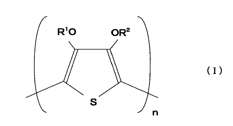
(式中、R1及びR2は、それぞれ独立して水素原子若しくは炭素原子数1~4のアルキル基を表し、又はR1及びR2が相互に結合して任意に置換されていても良い炭素原子数1~4のアルキレン基を形成し、nは50~1000の整数を表す)で表される繰り返し単位を含むポリチオフェン誘導体である。上記のポリチオフェン誘導体は導電性が高いので本発明における熱線反射層に含有させる導電性高分子として好適である。
(7)前記熱線反射層の総層厚が、10~3000nmである。
(1)前記金属ナノ繊維が、銀からなる。
(2)前記熱線反射層が、バインダ樹脂を含む塗工層である。低コストで製造可能な熱線遮蔽フィルムとすることができる。
(3)前記熱線反射層が、更に導電性高分子を含む。これにより、更に熱線反射性に優れ、且つ可視光透過率に優れた熱線遮蔽フィルムとすることができる。
(4)(3)において、前記熱線反射層が、金属ナノ繊維を含む第1の熱線反射層と、導電性高分子からなる第2の熱線反射層とからなる。通常、第2の熱線反射層は金属ナノ繊維を含まない。
(5)(4)において、前記第1の熱線反射層が最表層に形成されている。より効果的に熱線反射性を発揮させることができる。
(6)(3)~(5)において、前記導電性高分子が、下記式(I):
(7)前記熱線反射層の総層厚が、10~3000nmである。
また、上記目的は、本発明の熱線遮蔽フィルムが、前記熱線反射層が設けられた面と反対側の面で透明基板に接着されたことを特徴とする熱線遮蔽ウィンドウによって達成される。これにより、断熱性に優れ、且つ可視光透過性に優れ、低コストで製造可能な熱線遮蔽ウィンドウとすることができる。
更に、上記目的は、本発明の熱線遮蔽フィルムが、前記熱線反射層が設けられた面と反対側の面で透明基板に接着された積層体と、別の透明基板とが、間隙をおいて、前記熱線反射層が前記別の透明基板と対向するように配置され、その間隙により中空層が形成されていることを特徴とする熱線遮蔽ウィンドウによって達成される。2枚の透明基板の間隙に中空層を有するウィンドウは、一般に、複層ガラスといわれるものである。これにより、中空層による断熱性を付与することができるとともに、本発明の熱線遮蔽フィルムの熱線反射層を、雨水、結露、湿気等の水分から保護することができ、長期間、断熱性能を維持することができる。なお、前記中空層は、前記積層体と前記別の透明基板とがスペーサーを介して配置されることで形成されていることが好ましい。更にスペーサー内には乾燥剤を入れておくのが好ましい。
本発明によれば、熱線遮蔽フィルムの熱線反射層が金属ナノ繊維を含んでいるので、室内から放射される暖房等の熱線を反射して逃がさず、外気の熱を室内に取り込まない断熱性に優れ、且つ可視光透過性に優れた熱線遮蔽フィルムとすることができる。また、金属ナノ繊維を含む熱線反射層は、バインダ樹脂とともに低コストな塗工法で形成できるので、本発明の熱線遮蔽フィルムは低コストで製造可能である。
また、本発明の熱線遮蔽ウィンドウは、本発明の熱線遮蔽フィルムを使用しているので、断熱性に優れ、可視光透過性の高い安価な熱線遮蔽ウィンドウであるといえる。
以下に図面を参照しながら本発明の実施の形態を詳細に説明する。図1は本発明の熱線遮蔽フィルムの一例を示す概略断面図である。
図1に示した熱線遮蔽フィルム10は、透明フィルム13(透明プラスチックフィルム)、及びその表面に形成された金属ナノ繊維を含む熱線反射層14から構成されている。熱線反射層14は金属ナノ繊維を含んでいれば良く、どのように形成されたものでも良い。低コストで層形成できることから、金属ナノ繊維及びバインダ樹脂を含む塗工液を透明フィルム13の表面に塗工することで形成された塗工層であることが好ましい。
本発明の熱線遮蔽フィルム10は、金属ナノ繊維を含む熱線反射層14を有していることにより熱線反射性、即ち、赤外線を効果的に反射して、放射率を抑制する効果(低放射性)を発揮することができる。また、金属ナノ繊維は可視光域の波長に対して透過性が高いため、熱線反射層14は高い可視光透過性を有する。
金属ナノ繊維は、金属ナノワイヤー又は金属ナノロッドとも称されるサブミクロンレベルの微細な金属繊維である。金属ナノ繊維の短軸の長さは500nm未満が好ましく、200nm未満がより好ましく、100nm未満が更に好ましい。アスペクト比(長軸の長さ/短軸の長さ)は、一般に、10~100000の範囲であり、50~100000が好ましく、100~100000が更に好ましい。
金属ナノ繊維を構成する金属としては、金属元素、金属合金、金属酸化物等の金属化合物を含む。金属としては銀、金、銅、ニッケル、金めっきの銀が好ましく、特に銀が好ましい。
金属ナノ繊維は、従来公知の技術で調製できる。例えば、銀ナノ繊維は、エチレングリコール等のポリオール及びポリ(ビニルピロリドン)の存在下で硝酸銀等の銀塩の液相還元により合成できる。
熱線反射層14は金属ナノ繊維の放射抑制効果を妨げない範囲で、上述のバインダ樹脂やその他の材料を含んでいても良い。その他の材料としては、特に、導電性高分子が好ましく挙げられる。導電性高分子も赤外線を効果的に遮断し、断熱性を発揮するからである。これは導電性高分子の自由電子によるプラズマ吸収波長が、地上気温付近の物体の放射よりも短波長側にあり、そのプラズマ吸収波長より高波長の電磁波を反射するためと考えられる。導電性高分子を含むことにより、可視光透過性を低下させることなく熱線反射層14の低放射性を更に高めることができる。導電性高分子についての詳細は後述する。
熱線反射層14の層厚は、好ましくは10~3000nm、更に好ましくは20~1000nm、特に好ましくは30~500nmである。
なお、本発明の熱線遮蔽フィルム10には、熱線反射層14以外の別の層を有していても良い。この場合、熱線反射層14は、図1に示すように熱線遮蔽フィルム10の最表層に形成されていることが好ましいが、金属ナノ繊維の放射抑制効果を妨げない範囲で、導電性がある(金属)薄膜や、導電性がない有機樹脂の薄膜が、熱線反射層14の上に形成されていても良い。また、図2に示すように、上述の導電性高分子からなる別の熱線反射層が形成されていても良い。
図2は本発明の熱線遮蔽フィルムの別の一例を示す概略断面図である。図2に示した熱線遮蔽フィルム20は、透明フィルム23(透明プラスチックフィルム)、その表面に形成された導電性高分子からなる第2の熱線反射層25、及びその表面に形成された金属ナノ繊維を含む第1の熱線反射層24から構成されている。
第1の熱線反射層24は、図1における熱線反射層14と同様であり、金属ナノ繊維及びバインダ樹脂を含む塗工層であることが好ましい。
導電性高分子からなる第2の熱線反射層25は、通常、金属ナノ繊維を含まない。本発明の熱線遮蔽フィルムにおいて、熱線反射層が第1の熱線反射層24及び第2の熱線反射層25からなることで、更に効果的に放射抑制効果を発揮することができる。
図2においては、第1の熱線反射層24が最表層に形成されているが、金属ナノ繊維を含む第1の熱線反射層24が透明フィルム23の表面に形成され、その表面に導電性高分子からなる第2の熱線反射層25が形成されていても良い。より効率的に放射抑制効果が得られる点で、図2に示すように金属ナノ繊維を含む第1の熱線反射層が最表層に形成されていることが好ましい。
第1の熱線反射層の層厚は、好ましくは10~3000nm、更に好ましくは20~500nm、特に好ましくは50~300nmである。
第2の熱線反射層の層厚は、好ましくは10~3000nm、更に好ましくは50~2000nm、特に好ましくは100~1000nmである。
この場合、熱線反射層の総層厚として、10~3000nmが好ましく、更に70~2500nmが好ましく、特に150~1300nmが好ましい。
本発明において、熱線反射層に含まれ得る導電性高分子は、一般に共役型の二重結合を基本骨格に有する有機高分子で、具体的にはポリチオフェン、ポリピロール、ポリアニリン、ポリアセチレン、ポリパラフェニレン、ポリフラン、ポリフルオレン、ポリフェニレンビニレン、これらの誘導体、及びこれらを構成する単量体の共重合物から選ばれた導電性高分子のいずれか1種又は2種以上の混合物が好ましく挙げられる。中でも、水又はその他の溶媒に対して可溶性、又は分散性を有し、高い導電性及び透明性を示す、ポリチオフェン誘導体が好ましい。特に、下記式(I):
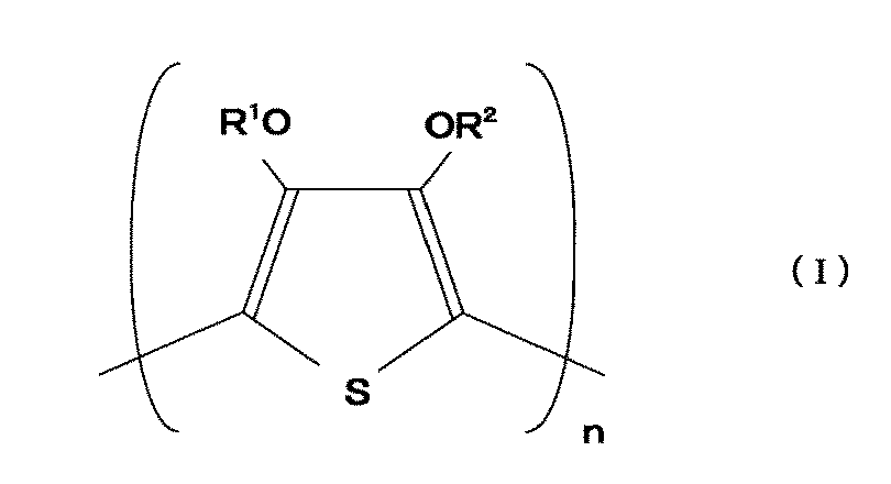
(式中、R1及びR2は、それぞれ独立して水素原子若しくは炭素原子数1~4のアルキル基を表し、又はR1及びR2が相互に結合して任意に置換されていても良い炭素原子数1~4のアルキレン基を形成し、nは50~1000の整数を表す)で表される繰り返し単位を含むポリチオフェン誘導体が好ましい。
式(I)において、R1及びR2が相互に結合して形成される、置換されていても良い炭素原子数1~4のアルキレン基としては、具体的にはアルキル基で置換されたメチレン基、任意に炭素原子数1~12のアルキル基又はフェニル基で置換されたエチレン-1,2基、プロピレン-1,3基、ブテン-1,4基を形成する基等が挙げられる。
式(I)におけるR1及びR2として、好ましくはメチル基又はエチル基であるか、R1及びR2が相互に結合して形成するメチレン基、エチレン-1,2基又はプロピレン-1,3基である。特に好ましいポリチオフェン誘導体としては、下記式(II):
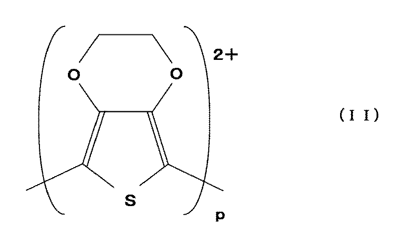
(式中、pは50~1000の整数を表す)で示される繰り返し単位、即ち、ポリ(3,4-エチレンジオキシチオフェン)単位を有するポリチオフェン誘導体である。
導電性高分子は、更にドーパント(電子供与剤)を含むことが好ましい。ドーパントとしては、例えば、ポリスチレンスルホン酸、ポリアクリル酸、ポリメタクリル酸、ポリマレイン酸、ポリビニルスルホン酸が好ましく挙げられる。特に、ポリスチレンスルホン酸が好ましい。これらにより導電性高分子の導電性を向上することができ、熱線反射層14の近赤外線遮蔽効果を高めることができる。ドーパントの数平均分子量Mnは、好ましくは1,000~2,000,000であり、特に好ましくは2,000~500,000である。
ドーパントの含有量は導電性高分子100質量部に対して、通常20~2000質量部であり、好ましくは、40~200質量部である。例えば、式(II)のポリチオフェン誘導体を導電性高分子とし、ポリスチレンスルホン酸をドーパントとして使用する場合はポリチオフェン100質量部に対して、ポリスチレンスルホン酸100~200質量部が好ましく、特に120~180質量部が好ましい。
本発明の熱線遮蔽フィルムの熱線反射層は、従来公知の方法で形成できる。例えば、金属ナノ繊維をバインダ樹脂等とともに溶媒に分散させた塗工液を、透明フィルム(又は別の層)の表面に、バーコーター法、ロールコーター法、カーテンフロー法、スプレー法など適当な方法を用いて塗工し、乾燥し、必要に応じて硬化して形成することができる。このウェットコーティング法であれば、高速で均一に且つ安価に成膜できるという利点がある。
バインダ樹脂としては、塗工層の形状を維持できればどのようなものでも良い。例えば紫外線硬化性樹脂組成物又は熱硬化性樹脂組成物を使用できる。紫外線硬化性樹脂又は熱硬化性樹脂としては、フェノール樹脂、レゾルシノール樹脂、尿素樹脂、メラミン樹脂、エポキシ樹脂、アクリル樹脂、ウレタン樹脂、フラン樹脂、シリコン樹脂、ポリエステル樹脂、ポリビニルアルコール樹脂などを挙げることができ、紫外線硬化性樹脂は光重合開始剤等とともに紫外線硬化性樹脂組成物とし、熱硬化性樹脂は熱重合開始剤等とともに熱硬化性樹脂組成物として使用する。
紫外線硬化性樹脂(モノマー、オリゴマー)としては、例えば、(メタ)アクリレートモノマー類、ポリオール化合物と有機ポリイソシアネートと水酸基含有(メタ)アクリレートの反応物であるポリウレタン(メタ)アクリレート、ビスフェノール型エポキシ樹脂と(メタ)アクリル酸の反応物であるビスフェノール型エポキシ(メタ)アクリレート等の(メタ)アクリレートオリゴマー類等を挙げることができる。これら化合物は1種又は2種以上、混合して使用することができる。特に、ペンタエリスリトールトリ(メタ)アクリレート、ペンタエリスリトールペンタ(メタ)アクリレート、ジペンタエリスリトールヘキサ(メタ)アクリレート、トリメチロールプロパントリ(メタ)アクリレート等の硬質の多官能モノマーを主に使用することが好ましい。
これらの紫外線硬化性樹脂を、熱重合開始剤とともに用いて熱硬化性樹脂として使用してもよい。
紫外線硬化性樹脂の光重合開始剤として、紫外線硬化性樹脂の性質に適した任意の化合物を使用することができる。例えば、1-ヒドロキシシクロヘキシルフェニルケトン等のアセトフェノン系、ベンジルジメチルケタール等のベンゾイン系、ベンゾフェノン等のベンゾフェノン系、チオキサントン系等が使用できる。特に、特に1-ヒドロキシシクロヘキシルフェニルケトン(BASFジャパン社製、イルガキュア184)が好ましい。光重合開始剤の量は、樹脂組成物に対して一般に0.1~10質量%、好ましくは0.1~5質量%である。
熱硬化性樹脂の熱重合開始剤として、加熱により重合を開始させる官能基を含む化合物である有機過酸化物やカチオン重合開始剤が挙げられ、中でも有機過酸化物が好ましい。
熱重合開始剤は、1種又は2種以上の混合で使用することができる。熱重合開始剤の量は、樹脂組成物に対して、一般に0.01~10質量%、好ましくは0.1~5質量%である。
金属ナノ繊維をバインダ樹脂とともに分散させる溶媒としては、水、アルコール、ケトン類、テトラヒドロフラン、シクロヘキサン等の炭化水素、ベンゼン、トルエン等の芳香族溶剤が挙げられる。
熱線反射層は、必要に応じて、紫外線吸収剤、赤外線吸収剤、老化防止剤、塗料加工助剤、着色剤等を少量含んでいても良い。その量は、樹脂組成物に対して一般に0.1~10質量%、好ましくは0.1~5質量%である。
バインダ樹脂として紫外線硬化性樹脂を用いる場合、紫外線硬化の光源として紫外~可視領域に発光する多くのものが採用でき、例えば超高圧、高圧、低圧水銀灯、ケミカルランプ、キセノンランプ、ハロゲンランプ、マーキュリーハロゲンランプ、カーボンアーク灯、白熱灯、レーザ光等を挙げることができる。照射時間は、ランプの種類、光源の強さによって一概には決められないが、数秒~数分程度である。また、硬化促進のために、予め積層体を40~120℃に加熱し、これに紫外線を照射してもよい。
本発明の熱線遮蔽フィルムの熱線反射層が導電性高分子を含む場合(図1の熱線反射層14に導電性高分子を含む場合、又は図2の第2の熱線反射層の場合)、熱線反射層は、従来公知の方法で形成できる。例えば、導電性高分子が溶解又は分散した塗工液を、透明フィルムの表面(又は別の層)の表面に、バーコーター法、ロールコーター法、カーテンフロー法、スプレー法など適当な方法を用いて塗工し、乾燥して形成する。塗工液に用いる溶媒としては、水;メタノール、エタノール、プロパノール等のアルコール類;アセトフェノン、メチルエチルケトン等のケトン類;四塩化炭素及びフッ化炭化水素等のハロゲン化炭化水素;酢酸エチル、酢酸ブチル等のエステル類;テトラヒドロフラン、ジオキサン、ジエチルエーテル等のエーテル類;N,N-ジメチルアセトアミド、N,N-ジメチルホルムアミド、N-メチルピロリドン等のアミド類が好ましく挙げられる。特に、水、アルコール類が好ましい。
なお、熱線反射層が金属ナノ繊維と導電性高分子とを含む場合(図1の熱線反射層14に導電性高分子を含む場合)は、更に上述のバインダ樹脂を加えた塗工液により層形成しても良く、導電性高分子をバインダ樹脂として用いた塗工液により層形成しても良い。
[透明フィルム]
本発明における透明フィルムは、通常、透明プラスチックフィルムである。透明プラスチックフィルムは、透明(「可視光に対して透明」を意味する。)なプラスチックフィルムであれば特に制限はない。プラスチックフィルムの例としては、ポリエチレンテレフタレート(PET)フィルム、ポリエチレンナフタレート(PEN)フィルム、ポリエチレンブチレートフィルム、トリアセチルセルロース(TAC)フィルム、ポリメチルメタクリレート(PMMA)フィルム、ポリカーボネート(PC)フィルム等を挙げることができ、特に加工時の熱、溶剤、折り曲げ等の負荷に対する耐性が高く、透明性が高い点で、PETフィルムが好ましい。
本発明における透明フィルムは、通常、透明プラスチックフィルムである。透明プラスチックフィルムは、透明(「可視光に対して透明」を意味する。)なプラスチックフィルムであれば特に制限はない。プラスチックフィルムの例としては、ポリエチレンテレフタレート(PET)フィルム、ポリエチレンナフタレート(PEN)フィルム、ポリエチレンブチレートフィルム、トリアセチルセルロース(TAC)フィルム、ポリメチルメタクリレート(PMMA)フィルム、ポリカーボネート(PC)フィルム等を挙げることができ、特に加工時の熱、溶剤、折り曲げ等の負荷に対する耐性が高く、透明性が高い点で、PETフィルムが好ましい。
なお、透明プラスチックフィルム表面には、接着性を向上させるために、予めコロナ処理、プラズマ処理、火炎処理、プライマー層コート処理などの接着処理を施してもよく、共重合ポリエステル樹脂やポリウレタン樹脂等の熱硬化性樹脂等の易接着層を設けてもよい。透明プラスチックフィルムの厚さは、一般に、1μm~10mm、好ましくは10~400μmであり、特に20~200μmが好ましい。
本発明の熱線遮蔽フィルムは、フィルム状のまま用いても良いが、一般に、接着剤層を設け、ガラス板等の透明基板に接着して用いる。
[熱線遮蔽ウィンドウ]
本発明の熱線遮蔽ウィンドウは、本発明の熱線遮蔽フィルムをガラス板等の透明基板に接着したものである。以下に、本発明の熱線遮蔽ウィンドウについて図面を参照しながら説明する。
本発明の熱線遮蔽ウィンドウは、本発明の熱線遮蔽フィルムをガラス板等の透明基板に接着したものである。以下に、本発明の熱線遮蔽ウィンドウについて図面を参照しながら説明する。
図3は、本発明の熱線遮蔽ウィンドウの一例を示す概略断面図である。図3に示す熱線遮蔽ウィンドウ30は、図1で説明した本発明の熱線遮蔽フィルム10(透明フィルム13の表面に金属ナノ繊維を含む熱線反射層14が形成されている)を、熱線反射層14が形成された面の反対側の面で、接着剤層32を介して、透明基板31に接着したものである。
熱線遮蔽ウィンドウ30は、熱線遮蔽フィルム10が、熱線反射層14が設けられている面と反対側の面で貼着されていることにより、熱線反射層14の放射抑制効果が十分に機能される。従って、本発明の熱線遮蔽ウィンドウは、断熱性に優れ、且つ可視光透過性に優れ、低コストで製造可能な熱線遮蔽ウィンドウということができる。
以下に、本発明の熱線遮蔽ウィンドウを構成する要素について説明する。
[透明基板]
本発明における透明基板31は、例えば、グリーンガラス、珪酸塩ガラス、無機ガラス板、無着色透明ガラス板などのガラス板の他、ポリエチレンテレフタレート(PET)、ポリエチレンナフタレート(PEN)、ポリエチレンブチレート、ポリメチルメタクリレート(PMMA)、ポリカーボネート等のプラスチック製の基板を用いてもよい。耐熱性、耐候性、耐衝撃性等の点でガラス板が好ましく、ガラス板の厚さは、2~20mm程度が一般的である。
本発明における透明基板31は、例えば、グリーンガラス、珪酸塩ガラス、無機ガラス板、無着色透明ガラス板などのガラス板の他、ポリエチレンテレフタレート(PET)、ポリエチレンナフタレート(PEN)、ポリエチレンブチレート、ポリメチルメタクリレート(PMMA)、ポリカーボネート等のプラスチック製の基板を用いてもよい。耐熱性、耐候性、耐衝撃性等の点でガラス板が好ましく、ガラス板の厚さは、2~20mm程度が一般的である。
[接着剤層]
本発明における接着剤層32は、エチレン-酢酸ビニル共重合体(EVA)、エチレン-アクリル酸メチル共重合体、エチレン-(メタ)アクリル酸共重合体、エチレン-(メタ)アクリル酸エチル共重合体、エチレン-(メタ)アクリル酸メチル共重合体、金属イオン架橋エチレン-(メタ)アクリル酸共重合体、部分鹸化エチレン-酢酸ビニル共重合体、カルボキシル化エチレン-酢酸ビニル共重合体、エチレン-(メタ)アクリル-無水マレイン酸共重合体、エチレン-酢酸ビニル-(メタ)アクリレート共重合体などのエチレン系共重合体を使用することができる(なお、「(メタ)アクリル」は「アクリル又はメタクリル」を示す。)。また、接着剤層には、ポリビニルブチラール(PVB)樹脂、エポキシ樹脂、フェノール樹脂、シリコーン樹脂、ポリエステル樹脂、ウレタン樹脂、ゴム系粘着剤、SEBS及びSBS等の熱可塑性エラストマー等も用いることができる。なかでも、優れた接着性を示し、高い透明性を有することからEVAを用いるのが好ましい。
本発明における接着剤層32は、エチレン-酢酸ビニル共重合体(EVA)、エチレン-アクリル酸メチル共重合体、エチレン-(メタ)アクリル酸共重合体、エチレン-(メタ)アクリル酸エチル共重合体、エチレン-(メタ)アクリル酸メチル共重合体、金属イオン架橋エチレン-(メタ)アクリル酸共重合体、部分鹸化エチレン-酢酸ビニル共重合体、カルボキシル化エチレン-酢酸ビニル共重合体、エチレン-(メタ)アクリル-無水マレイン酸共重合体、エチレン-酢酸ビニル-(メタ)アクリレート共重合体などのエチレン系共重合体を使用することができる(なお、「(メタ)アクリル」は「アクリル又はメタクリル」を示す。)。また、接着剤層には、ポリビニルブチラール(PVB)樹脂、エポキシ樹脂、フェノール樹脂、シリコーン樹脂、ポリエステル樹脂、ウレタン樹脂、ゴム系粘着剤、SEBS及びSBS等の熱可塑性エラストマー等も用いることができる。なかでも、優れた接着性を示し、高い透明性を有することからEVAを用いるのが好ましい。
接着剤層に用いられるEVAは、酢酸ビニル含有率が、EVA100質量部に対して、23~38質量部であり、特に23~28質量部であることが好ましい。これにより接着性及び透明性に優れる接着剤層を得ることができる。またEVAのメルト・フロー・インデックス(MFR)が、4.0~30.0g/10分、特に8.0~18.0g/10分であることが好ましい。予備圧着が容易になる。
接着剤層にエチレン系共重合体を用いる場合、更に有機過酸化物を含むのが好ましい。有機過酸化物により架橋硬化させることにより、隣接する層とガラス板等を更に接合一体化することができる。有機過酸化物としては、100℃以上の温度で分解してラジカルを発生するものであれば、どのようなものでも併用することもできる。有機過酸化物は、一般に、成膜温度、組成物の調整条件、硬化(貼り合わせ)温度、被着体の耐熱性、貯蔵安定性を考慮して選択される。特に、半減期10時間の分解温度が70℃以上のものが好ましい。
この有機過酸化物の例としては、2,5-ジメチルヘキサン-2,5-ジハイドロパーオキサイド、2,5-ジメチル-2,5-ジ(t-ブチルパーオキシ)ヘキサン-3-ジ-t-ブチルパーオキサイド、t-ブチルクミルパーオキサイド、2,5-ジメチル-2,5-ジ(t-ブチルパーオキシ)ヘキサン、ジクミルパーオキサイド、α,α’-ビス(t-ブチルパーオキシイソプロピル)ベンゼン、n-ブチル-4,4-ビス(t-ブチルパーオキシ)バレレート、1,1-ビス(t-ブチルパーオキシ)シクロヘキサン、1,1-ビス(t-ブチルパーオキシ)-3,3,5-トリメチルシクロヘキサン、t-ブチルパーオキシベンゾエート、ベンゾイルパーオキサイド、t-ブチルパーオキシアセテート、メチルエチルケトンパーオキサイド、2,5-ジメチルヘキシル-2,5-ビスパーオキシベンゾエート、ブチルハイドロパーオキサイド、p-メンタンハイドロパーオキサイド、p-クロロベンゾイルパーオキサイド、ヒドロキシヘプチルパーオキサイド、クロロヘキサノンパーオキサイド、オクタノイルパーオキサイド、デカノイルパーオキサイド、ラウロイルパーオキサイド、クミルパーオキシオクトエート、コハク酸パーオキサイド、アセチルパーオキサイド、m-トルオイルパーオキサイド、t-ブチルパーオキシイソブチレーオ及び2,4-ジクロロベンゾイルパーオキサイドを挙げることができる。
また、接着剤層は、更に架橋助剤や接着向上剤としてシランカップリング剤を含むのが好ましい。
架橋助剤としては、グリセリン、トリメチロールプロパン、ペンタエリスリトール等に複数のアクリル酸あるいはメタクリル酸をエステル化したエステル、トリアリルシアヌレート、トリアリルイソシアヌレートなどの多官能化合物を挙げることができる。
シランカップリング剤の例として、γ-クロロプロピルメトキシシラン、ビニルエトキシシラン、ビニルトリス(β-メトキシエトキシ)シラン、γ-メタクリロキシプロピルトリメトキシシラン、ビニルトリアセトキシシラン、γ-グリシドキシプロピルトリメトキシシラン、γ-グリシドキシプロピルトリエトキシシラン、β-(3,4-エポキシシクロヘキシル)エチルトリメトキシシラン、ビニルトリクロロシラン、γ-メルカプトプロピルトリメトキシシラン、γ-アミノプロピルトリエトキシシラン、N-β-(アミノエチル)-γ-アミノプロピルトリメトキシシランを挙げることができる。これらシランカップリング剤は、単独で使用しても、又は2種以上組み合わせて使用しても良い。また上記化合物の含有量は、エチレン系共重合体100質量部に対して5質量部以下であるこ
とが好ましい。
とが好ましい。
接着樹脂層は、種々の物性(機械的強度、接着性、透明性等の光学的特性、耐熱性、耐光性、架橋速度等)の改良あるいは調整、特に機械的強度、耐光性の改良のため、アクリロキシ基含有化合物、メタクリロキシ基含有化合物、エポキシ基含有化合物、可塑剤、紫外線吸収剤を含んでいることが好ましい。紫外線吸収剤としては、ベンゾフェノン系化合物、トリアジン系化合物、ベンゾエート系化合物及び、ヒンダードアミン系化合物を挙げることができる。黄変を抑制する観点から、ベンゾフェノン系化合物が好ましい。上記紫外線吸収剤は、エチレン系共重合体100質量部に対して0.01~1.5質量部(特に0.5~1.0質量部)使用することが好ましい。
接着剤層の厚さは、100~2000μm、特に400~1000μmであるのが好ましい。
エチレン系共重合体を含む接着剤層を作製するには、例えば、エチレン系共重合体及び有機過酸化物等を含む組成物を、通常の押出成形、カレンダ成形(カレンダリング)等により成形して層状物を得る方法などを用いることができる。組成物の混合は、40~90℃、特に60~80℃の温度で加熱混練することにより行うのが好ましい。また、製膜時の加熱温度は、架橋剤が反応しない或いはほとんど反応しない温度とすることが好ましい。例えば、40~90℃、特に50~80℃とするのが好ましい。接着剤層は透明プラスチックフィルムや透明基板の表面に直接形成しても良く、別途、フィルム状の接着剤シートを使用して形成しても良い。
図3に示す熱線遮蔽ウィンドウ30を製造するには、例えば、図1に示した本発明の熱線遮蔽フィルム10、及び透明基板31を用意し、上記のような接着剤層32(熱線遮蔽フィルムの熱線反射層を形成した面と反対側の面に接着剤層を形成するか、接着剤シートをガラス板上に積層する)を介して、上記の熱線遮蔽フィルム10と透明基板31を積層した積層体を脱気した後、加熱下(好ましくは40~200℃で1~120分間、特に60~150℃で1~20分間)に押圧(好ましくは1.0×10³Pa~5.0×10⁷Paの圧力)して接着一体化すれば良い。これらの工程は例えば、真空袋方式、ニップロール方式等で行うことができる。
例えば、接着剤層32にEVAを使用した場合、一般に100~150℃(特に130℃付近)で、10分~1時間架橋させる。これは、積層体を脱気したのち、例えば80~120℃の温度で予備圧着し、100~150℃(特に130℃付近)で、10分~1時間加熱処理することにより行われる。架橋後の冷却は一般に室温で行われるが、特に、冷却は速いほど好ましい。
また、図4は、本発明の熱線遮蔽ウィンドウの別の一例を示す概略断面図である。図4に示す熱線遮蔽ウィンドウ50は、透明基板41の一方の表面に、本発明の熱線遮蔽フィルム10(透明フィルム13の表面に金属ナノ繊維を含む熱線反射層14が形成されている)を、熱線反射層14が形成された面の反対側の面で、接着剤層42を介して接着した積層体40、積層体40と間隙をおいて対向するように配置された別の透明基板47、これらの外周部に配置され、接着剤(図示していない)によりこれらを接合しているスペーサー49、及びスペーサー49によって積層体40と別の透明基板47との間に形成された中空層48から構成されている。即ち、熱線遮蔽ウィンドウ50は、一般に複層ガラスといわれる構成を備えている(複層ガラス型の熱線遮蔽ウィンドウともいう)。
積層体40は、上述の熱線遮蔽ウィンドウ30と同様な構成である。そして、熱線遮蔽ウィンドウ50は、中空層48が形成されていることにより、更に断熱性を付与される。
また、熱線遮蔽ウィンドウ50において、積層体30は、熱線反射層14が別の透明基板47に対向するように配置されている。これにより、熱線反射層14を雨水、結露、湿気等の水分から保護するとともに擦り傷、掻き傷等の物理的損傷からも保護することができ、断熱性及び可視光透過性を長期間維持することができる。
従って、本発明の複層ガラスは、断熱性に優れ、且つ可視光透過性に優れ、低コストで製造可能な複層ガラス型の熱線遮蔽ウィンドウということができる。
別の透明基板47としては、上述の透明基板31と同様なものの他、表面処理により光拡散機能を備えたすりガラス、網入りガラス、線入板ガラス、強化ガラス、倍強化ガラス、低反射ガラス、高透過板ガラス、セラミック印刷ガラス、熱線や紫外線吸収機能を備えた特殊ガラス等、種々のガラスを適宜選択して用いることができる。
中空層としては、空気層、不活性ガス層などが用いられる。これらの中空層によれば、複層ガラス型の熱線遮蔽ウィンドウに求められる断熱性を向上するとともに、熱線反射層24の経時的劣化を抑制することができる。空気層は、スペーサー39内に乾燥剤を入れることにより乾燥空気を用いてもよい。不活性ガス層は、例えばクリプトンガス、アルゴンガス、及びキセノンガスなどの不活性ガスを含む。中空層の厚さは、6~12mmであるのが好ましい。
本発明の熱線遮蔽ウィンドウの形状は、用途に応じて、矩形状、丸状、菱形状など、種々の形状とすることができる。用途についても、建築物や乗り物(自動車、鉄道車両、船舶)用の窓ガラス、あるいは、プラズマディスプレイなどの機器要素をはじめとして、冷蔵庫や保温装置などのような各種装置の扉や壁部など、種々の用途に使用することができる。
以下に、実施例を示し、本発明についてさらに詳述する。
1.熱線遮蔽フィルムの作製
1.熱線遮蔽フィルムの作製
[実施例1]
PETフィルム(厚さ100μm)の表面に、銀ナノ繊維分散液(銀ナノ繊維(直径40nm、長さ40μm)、バインダ樹脂(ポリビニルアルコール)、溶媒(水)(固形分2質量%))をバーコーターにより塗工し、120℃、1分間乾燥して、厚さ50nmの熱線反射層を形成し、熱線遮蔽フィルムを作製した。
PETフィルム(厚さ100μm)の表面に、銀ナノ繊維分散液(銀ナノ繊維(直径40nm、長さ40μm)、バインダ樹脂(ポリビニルアルコール)、溶媒(水)(固形分2質量%))をバーコーターにより塗工し、120℃、1分間乾燥して、厚さ50nmの熱線反射層を形成し、熱線遮蔽フィルムを作製した。
[実施例2]
熱線反射層の厚さを100nmとした以外は、実施例1と同様に熱線遮蔽フィルムを作製した。
熱線反射層の厚さを100nmとした以外は、実施例1と同様に熱線遮蔽フィルムを作製した。
[実施例3]
PETフィルム(厚さ100μm)の表面に、導電性高分子としてポリ(3,4-エチレンジオキシチオフェン)及びポリスチレンスルホン酸の混合物の水分散液(Baytron P HC V4(HC スタルク社製)固形分1.3質量%)をバーコーターにより塗工し、120℃、1分間乾燥して、厚さ400nmの第2の熱線反射層を形成し、その表面に、実施例1と同様な銀ナノ繊維分散液をバーコーターにより塗工し、120℃、1分間乾燥し、厚さ50nmの第1の熱線反射層を形成し、熱線遮蔽フィルムを作成した(図2参照)。
PETフィルム(厚さ100μm)の表面に、導電性高分子としてポリ(3,4-エチレンジオキシチオフェン)及びポリスチレンスルホン酸の混合物の水分散液(Baytron P HC V4(HC スタルク社製)固形分1.3質量%)をバーコーターにより塗工し、120℃、1分間乾燥して、厚さ400nmの第2の熱線反射層を形成し、その表面に、実施例1と同様な銀ナノ繊維分散液をバーコーターにより塗工し、120℃、1分間乾燥し、厚さ50nmの第1の熱線反射層を形成し、熱線遮蔽フィルムを作成した(図2参照)。
[実施例4]
塗工液を、実施例1と同様な銀ナノ繊維分散塗工液、及びポリ(3,4-エチレンジオキシチオフェン)及びポリスチレンスルホン酸の混合物の水分散液(Baytron P HC V4(HC スタルク社製)固形分1.3質量%)を質量比1:1で混合した塗工液とし、熱線反射層の厚さを500nmとした以外は実施例1と同様に熱線遮蔽フィルムを作製した。
塗工液を、実施例1と同様な銀ナノ繊維分散塗工液、及びポリ(3,4-エチレンジオキシチオフェン)及びポリスチレンスルホン酸の混合物の水分散液(Baytron P HC V4(HC スタルク社製)固形分1.3質量%)を質量比1:1で混合した塗工液とし、熱線反射層の厚さを500nmとした以外は実施例1と同様に熱線遮蔽フィルムを作製した。
[比較例1]
PETフィルム(厚さ100μm)を用いた。
PETフィルム(厚さ100μm)を用いた。
[比較例2]
PETフィルム(厚さ100μm)の表面に、ポリ(3,4-エチレンジオキシチオフェン)及びポリスチレンスルホン酸の混合物の水分散液(Baytron P HC V4(HC スタルク社製)固形分1.3質量%)をバーコーターにより塗工し、120℃、1分間乾燥して、厚さ50nmの熱線反射層を形成し、熱線遮蔽フィルムを作製した。
PETフィルム(厚さ100μm)の表面に、ポリ(3,4-エチレンジオキシチオフェン)及びポリスチレンスルホン酸の混合物の水分散液(Baytron P HC V4(HC スタルク社製)固形分1.3質量%)をバーコーターにより塗工し、120℃、1分間乾燥して、厚さ50nmの熱線反射層を形成し、熱線遮蔽フィルムを作製した。
[比較例3]
熱線反射層の厚さを500nmとした以外は、比較例2と同様に熱線遮蔽フィルムを作製した。
熱線反射層の厚さを500nmとした以外は、比較例2と同様に熱線遮蔽フィルムを作製した。
[比較例4]
PETフィルム(厚さ100μm)の表面に、下記配合の銀微粒子分散液をバーコーターにより塗工し、120℃、1分間乾燥して、厚さ50nmの熱線反射層を形成し、熱線遮蔽フィルムを作製した。
PETフィルム(厚さ100μm)の表面に、下記配合の銀微粒子分散液をバーコーターにより塗工し、120℃、1分間乾燥して、厚さ50nmの熱線反射層を形成し、熱線遮蔽フィルムを作製した。
(配合)
銀微粒子(ELCOM BS-5001AGV(触媒化成工業製)固形分3%)100質量部
ケイ素樹脂(固形分3%)50質量部
銀微粒子(ELCOM BS-5001AGV(触媒化成工業製)固形分3%)100質量部
ケイ素樹脂(固形分3%)50質量部
2.評価方法
(1)放射率
JISR3106に準拠して測定した。
(2)可視光透過率
分光光度計UV3100PC(島津製作所(株)製)により測定した透過スペクトルを用い、XYZ表色系の三刺激値のYを計算し、視感透過率(Y)を得た。計算方法は、C光源2°(JIS Z8722-2000)にて計算した。
(1)放射率
JISR3106に準拠して測定した。
(2)可視光透過率
分光光度計UV3100PC(島津製作所(株)製)により測定した透過スペクトルを用い、XYZ表色系の三刺激値のYを計算し、視感透過率(Y)を得た。計算方法は、C光源2°(JIS Z8722-2000)にて計算した。
3.評価結果
各熱線遮蔽フィルムの評価結果を表1に示す。
各熱線遮蔽フィルムの評価結果を表1に示す。
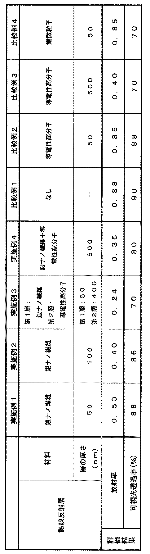
表1に示す通り、金属ナノ繊維として銀ナノ繊維を含む熱線反射層を有する実施例1~4の熱線遮蔽フィルムは、導電性高分子かなる熱線反射層を有する比較例2及び3に比べて、放射率が低く、優れた放射抑制効果を示すとともに、高い可視光透過率を示した。また、熱線反射層が銀ナノ繊維と導電性高分子とを含む実施例3及び4は更に優れた放射抑制効果を示した。なお、比較例4の結果から、銀微粒子を含む層には放射抑制効果は認められなかった。
なお、本発明は上記の実施の形態及び実施例に限定されるものではなく、発明の要旨の範囲内で種々変形が可能である。
オフィスビル等の建築物及びバス、乗用車、電車等の車両・鉄道等の空調負荷を効率的に低減できる熱線遮蔽ウィンドウを低コストで提供することができる。
10、20:熱線遮蔽フィルム
13、23:透明フィルム
14:熱線反射層
24:第1の熱線反射層
25:第2の熱線反射層
30:熱線遮蔽ウィンドウ
31、41、47:透明基板
32、42: 接着剤層
40:積層体
48:中空層
49:スペーサー
50:熱線遮蔽ウィンドウ(複層ガラス型)
13、23:透明フィルム
14:熱線反射層
24:第1の熱線反射層
25:第2の熱線反射層
30:熱線遮蔽ウィンドウ
31、41、47:透明基板
32、42: 接着剤層
40:積層体
48:中空層
49:スペーサー
50:熱線遮蔽ウィンドウ(複層ガラス型)
Claims (10)
- 透明フィルム、及びその表面に設けられた熱線反射層を含む熱線遮蔽フィルムであって、
熱線反射層が、金属ナノ繊維を含むことを特徴とする熱線遮蔽フィルム。 - 前記金属ナノ繊維が、銀からなる請求項1に記載の熱線遮蔽フィルム。
- 前記熱線反射層が、バインダ樹脂を含む塗工層である請求項1又は2に記載の熱線遮蔽フィルム。
- 前記熱線反射層が、更に導電性高分子を含む請求項1~3のいずれか1項に記載の熱線遮蔽フィルム。
- 前記熱線反射層が、金属ナノ繊維を含む第1の熱線反射層と、
導電性高分子からなる第2の熱線反射層とからなる請求項4に記載の熱線遮蔽フィルム。 - 前記第1の熱線反射層が最表層に形成されている請求項5に記載の熱線遮蔽フィルム。
- 前記導電性高分子が、下記式(I):

- 前記熱線反射層の総層厚が、10~3000nmである請求項1~7のいずれか1項に記載の熱線遮蔽フィルム。
- 請求項1~8のいずれか1項に記載の熱線遮蔽フィルムが、前記熱線反射層が設けられた面と反対側の面で透明基板に接着されたことを特徴とする熱線遮蔽ウィンドウ。
- 請求項1~8のいずれか1項に記載の熱線遮蔽フィルムが、前記熱線反射層が設けられた面と反対側の面で透明基板に接着された積層体と、別の透明基板とが、間隙をおいて、 前記熱線反射層が前記別の透明基板と対向するように配置され、その間隙により中空層が形成されていることを特徴とする熱線遮蔽ウィンドウ。
Applications Claiming Priority (2)
| Application Number | Priority Date | Filing Date | Title |
|---|---|---|---|
| JP2011-124840 | 2011-06-03 | ||
| JP2011124840A JP5798804B2 (ja) | 2011-06-03 | 2011-06-03 | 熱線遮蔽フィルム、これを用いた熱線遮蔽ウィンドウ |
Publications (1)
| Publication Number | Publication Date |
|---|---|
| WO2012165150A1 true WO2012165150A1 (ja) | 2012-12-06 |
Family
ID=47259013
Family Applications (1)
| Application Number | Title | Priority Date | Filing Date |
|---|---|---|---|
| PCT/JP2012/062599 Ceased WO2012165150A1 (ja) | 2011-06-03 | 2012-05-17 | 熱線遮蔽フィルム、これを用いた熱線遮蔽ウィンドウ |
Country Status (2)
| Country | Link |
|---|---|
| JP (1) | JP5798804B2 (ja) |
| WO (1) | WO2012165150A1 (ja) |
Cited By (7)
| Publication number | Priority date | Publication date | Assignee | Title |
|---|---|---|---|---|
| WO2015182745A1 (ja) * | 2014-05-30 | 2015-12-03 | 富士フイルム株式会社 | 窓用断熱フィルム、窓用断熱材および窓 |
| WO2016031489A1 (ja) * | 2014-08-27 | 2016-03-03 | 富士フイルム株式会社 | 断熱フィルム、断熱フィルムの製造方法、断熱ガラスおよび窓 |
| WO2016152595A1 (ja) * | 2015-03-25 | 2016-09-29 | 富士フイルム株式会社 | 遠赤外線反射フィルム、遠赤外線反射フィルム形成用の分散液、遠赤外線反射フィルムの製造方法、遠赤外線反射ガラスおよび窓 |
| CN106273951A (zh) * | 2016-10-20 | 2017-01-04 | 东莞市纳利光学材料有限公司 | 一种抗冲击隔热膜 |
| CN106457747A (zh) * | 2014-05-30 | 2017-02-22 | 富士胶片株式会社 | 窗户用隔热薄膜、窗户用隔热材料及窗户 |
| CN107835952A (zh) * | 2015-07-31 | 2018-03-23 | 富士胶片株式会社 | 热射线反射材料及窗、以及热射线反射材料的制造方法 |
| CN111527423A (zh) * | 2017-12-29 | 2020-08-11 | 3M创新有限公司 | 具有含氟聚合物的无源冷却制品 |
Families Citing this family (17)
| Publication number | Priority date | Publication date | Assignee | Title |
|---|---|---|---|---|
| FR2996358B1 (fr) * | 2012-10-03 | 2016-01-08 | Hutchinson | Electrode transparente et procede de fabrication associe |
| JP6243813B2 (ja) * | 2014-07-31 | 2017-12-06 | 富士フイルム株式会社 | 窓用断熱フィルム、窓用断熱フィルムの製造方法、窓用断熱ガラスおよび窓 |
| WO2016017658A1 (ja) * | 2014-07-31 | 2016-02-04 | 富士フイルム株式会社 | 窓用断熱フィルム、窓用断熱ガラスおよび窓 |
| JP6308469B2 (ja) * | 2014-09-29 | 2018-04-11 | タキロンシーアイ株式会社 | 難燃性積層体 |
| JP2016140989A (ja) * | 2015-01-30 | 2016-08-08 | 富士フイルム株式会社 | 断熱フィルム、断熱ガラスおよび窓 |
| JP2016140988A (ja) * | 2015-01-30 | 2016-08-08 | 富士フイルム株式会社 | 断熱フィルム、断熱ガラスおよび窓 |
| JP2016173499A (ja) * | 2015-03-17 | 2016-09-29 | 富士フイルム株式会社 | 断熱フィルム、断熱ガラスおよび窓 |
| JP2017031322A (ja) * | 2015-07-31 | 2017-02-09 | 富士フイルム株式会社 | 断熱塗料 |
| JP6559005B2 (ja) * | 2015-07-31 | 2019-08-14 | 富士フイルム株式会社 | 熱線反射材料及び窓 |
| JP2017044807A (ja) * | 2015-08-25 | 2017-03-02 | 富士フイルム株式会社 | 熱線反射材料及び窓 |
| CN106166883B (zh) * | 2016-06-17 | 2018-07-31 | 东莞市纳利光学材料有限公司 | 一种隔热膜及制备方法 |
| WO2017221633A1 (ja) * | 2016-06-21 | 2017-12-28 | コニカミノルタ株式会社 | サーモクロミックフィルム |
| CN106183276B (zh) * | 2016-07-15 | 2019-01-22 | 东莞市纳利光学材料有限公司 | 一种抗冲击隔热膜及其制备方法 |
| CN106313832B (zh) * | 2016-08-15 | 2019-01-25 | 东莞市纳利光学材料有限公司 | 一种隔热膜及其制备方法 |
| KR101884525B1 (ko) * | 2016-09-29 | 2018-08-29 | 연세대학교 산학협력단 | 공액계 고분자를 포함하는 농업용 열차단 필름 및 이의 제조방법 |
| LU100018B1 (en) * | 2017-01-11 | 2018-08-14 | Luxembourg Inst Science & Tech List | Infrared reflective and electrical conductive composite film and manufacturing method thereof |
| JP7434759B2 (ja) * | 2018-09-05 | 2024-02-21 | 大日本印刷株式会社 | 表示装置 |
Citations (4)
| Publication number | Priority date | Publication date | Assignee | Title |
|---|---|---|---|---|
| JP2003315531A (ja) * | 2002-02-25 | 2003-11-06 | Mitsubishi Materials Corp | 金属ナノロッド含有高分子フィルムと光学フィルター |
| JP2004238503A (ja) * | 2003-02-06 | 2004-08-26 | Mitsubishi Materials Corp | 金属ナノ繊維含有組成物およびその用途 |
| JP2010044409A (ja) * | 2009-10-29 | 2010-02-25 | Toyobo Co Ltd | 近赤外線吸収フィルム |
| WO2010150839A1 (ja) * | 2009-06-24 | 2010-12-29 | 株式会社ブリヂストン | 熱線遮蔽ガラス、及び熱線遮蔽複層ガラス |
Family Cites Families (1)
| Publication number | Priority date | Publication date | Assignee | Title |
|---|---|---|---|---|
| JP2007206260A (ja) * | 2006-01-31 | 2007-08-16 | Toyobo Co Ltd | 近赤外線吸収フィルムおよび製造方法 |
-
2011
- 2011-06-03 JP JP2011124840A patent/JP5798804B2/ja not_active Expired - Fee Related
-
2012
- 2012-05-17 WO PCT/JP2012/062599 patent/WO2012165150A1/ja not_active Ceased
Patent Citations (4)
| Publication number | Priority date | Publication date | Assignee | Title |
|---|---|---|---|---|
| JP2003315531A (ja) * | 2002-02-25 | 2003-11-06 | Mitsubishi Materials Corp | 金属ナノロッド含有高分子フィルムと光学フィルター |
| JP2004238503A (ja) * | 2003-02-06 | 2004-08-26 | Mitsubishi Materials Corp | 金属ナノ繊維含有組成物およびその用途 |
| WO2010150839A1 (ja) * | 2009-06-24 | 2010-12-29 | 株式会社ブリヂストン | 熱線遮蔽ガラス、及び熱線遮蔽複層ガラス |
| JP2010044409A (ja) * | 2009-10-29 | 2010-02-25 | Toyobo Co Ltd | 近赤外線吸収フィルム |
Cited By (12)
| Publication number | Priority date | Publication date | Assignee | Title |
|---|---|---|---|---|
| WO2015182745A1 (ja) * | 2014-05-30 | 2015-12-03 | 富士フイルム株式会社 | 窓用断熱フィルム、窓用断熱材および窓 |
| CN106457747A (zh) * | 2014-05-30 | 2017-02-22 | 富士胶片株式会社 | 窗户用隔热薄膜、窗户用隔热材料及窗户 |
| JPWO2015182745A1 (ja) * | 2014-05-30 | 2017-05-25 | 富士フイルム株式会社 | 窓用断熱フィルム、窓用断熱材および窓 |
| WO2016031489A1 (ja) * | 2014-08-27 | 2016-03-03 | 富士フイルム株式会社 | 断熱フィルム、断熱フィルムの製造方法、断熱ガラスおよび窓 |
| JPWO2016031489A1 (ja) * | 2014-08-27 | 2017-06-15 | 富士フイルム株式会社 | 断熱フィルム、断熱フィルムの製造方法、断熱ガラスおよび窓 |
| WO2016152595A1 (ja) * | 2015-03-25 | 2016-09-29 | 富士フイルム株式会社 | 遠赤外線反射フィルム、遠赤外線反射フィルム形成用の分散液、遠赤外線反射フィルムの製造方法、遠赤外線反射ガラスおよび窓 |
| JP2016180932A (ja) * | 2015-03-25 | 2016-10-13 | 富士フイルム株式会社 | 遠赤外線反射フィルム、遠赤外線反射フィルム形成用の分散液、遠赤外線反射フィルムの製造方法、遠赤外線反射ガラスおよび窓 |
| CN107209303A (zh) * | 2015-03-25 | 2017-09-26 | 富士胶片株式会社 | 远红外线反射薄膜、远红外线反射薄膜形成用分散液、远红外线反射薄膜的制造方法、远红外线反射玻璃及窗户 |
| CN107209303B (zh) * | 2015-03-25 | 2020-07-14 | 富士胶片株式会社 | 远红外线反射薄膜、远红外线反射薄膜形成用分散液、远红外线反射薄膜的制造方法、远红外线反射玻璃及窗户 |
| CN107835952A (zh) * | 2015-07-31 | 2018-03-23 | 富士胶片株式会社 | 热射线反射材料及窗、以及热射线反射材料的制造方法 |
| CN106273951A (zh) * | 2016-10-20 | 2017-01-04 | 东莞市纳利光学材料有限公司 | 一种抗冲击隔热膜 |
| CN111527423A (zh) * | 2017-12-29 | 2020-08-11 | 3M创新有限公司 | 具有含氟聚合物的无源冷却制品 |
Also Published As
| Publication number | Publication date |
|---|---|
| JP5798804B2 (ja) | 2015-10-21 |
| JP2012252172A (ja) | 2012-12-20 |
Similar Documents
| Publication | Publication Date | Title |
|---|---|---|
| JP5798804B2 (ja) | 熱線遮蔽フィルム、これを用いた熱線遮蔽ウィンドウ | |
| JP5778488B2 (ja) | 熱線遮蔽ガラス、及びこれを用いた複層ガラス | |
| WO2010150839A1 (ja) | 熱線遮蔽ガラス、及び熱線遮蔽複層ガラス | |
| CN102781868B (zh) | 热射线屏蔽多层玻璃 | |
| JP5559483B2 (ja) | 熱線遮蔽ガラス、及びこれを用いた複層ガラス | |
| JP5840830B2 (ja) | 熱線遮蔽複層ガラス | |
| JP5537845B2 (ja) | 熱線遮蔽ガラス、及びこれを用いた複層ガラス | |
| JP2009062411A (ja) | 近赤外線遮蔽体、これを用いた積層体及びディスプレイ用光学フィルタ、並びにディスプレイ | |
| JP5675312B2 (ja) | 熱線遮蔽ガラス、及びこれを用いた複層ガラス | |
| JP2010222160A (ja) | 熱線遮蔽ガラス、及びこれを用いた複層ガラス | |
| JP5368881B2 (ja) | 熱線遮蔽合わせガラス用中間膜、及び熱線遮蔽合わせガラス | |
| JP5674446B2 (ja) | 熱線遮蔽フィルム、これを用いた熱線遮蔽ガラス、及び複層ガラス | |
| JP5683841B2 (ja) | 熱線遮蔽フィルム、これを用いた熱線遮蔽ガラス、及び複層ガラス | |
| JPWO2005090504A1 (ja) | シート状接着剤及びそれを用いた積層体 | |
| JP5674293B2 (ja) | 熱線遮蔽ガラス、及びこれを用いた複層ガラス | |
| JP5680952B2 (ja) | 熱線遮蔽ガラス、及びこれを用いた複層ガラス | |
| JP2006293239A (ja) | 光学フィルタ、これを備えたディスプレイ及びプラズマディスプレイパネル | |
| JP5697900B2 (ja) | 熱線遮蔽複層ガラス | |
| JP5840831B2 (ja) | 熱線遮蔽複層ガラス | |
| JP2016140989A (ja) | 断熱フィルム、断熱ガラスおよび窓 | |
| JP5952528B2 (ja) | ウィンドウフィルム及びその製造方法、並びにそのウィンドウフィルムを用いたウィンドウ及びその製造方法 | |
| WO2006046726A1 (ja) | シート状接着剤及びその製造方法、並びにそれを用いた積層体 | |
| JP2008108877A (ja) | ディスプレイ用光学フィルタの製造方法、ディスプレイ用光学フィルタ、これを備えたディスプレイ及びプラズマディスプレイパネル | |
| JP2001278639A (ja) | フィルム強化ガラス |
Legal Events
| Date | Code | Title | Description |
|---|---|---|---|
| 121 | Ep: the epo has been informed by wipo that ep was designated in this application |
Ref document number: 12793222 Country of ref document: EP Kind code of ref document: A1 |
|
| NENP | Non-entry into the national phase |
Ref country code: DE |
|
| 122 | Ep: pct application non-entry in european phase |
Ref document number: 12793222 Country of ref document: EP Kind code of ref document: A1 |