WO2012157467A1 - 検査領域設定方法およびx線検査システム - Google Patents
検査領域設定方法およびx線検査システム Download PDFInfo
- Publication number
- WO2012157467A1 WO2012157467A1 PCT/JP2012/061741 JP2012061741W WO2012157467A1 WO 2012157467 A1 WO2012157467 A1 WO 2012157467A1 JP 2012061741 W JP2012061741 W JP 2012061741W WO 2012157467 A1 WO2012157467 A1 WO 2012157467A1
- Authority
- WO
- WIPO (PCT)
- Prior art keywords
- inspection
- image
- ray
- substrate
- inspection object
- Prior art date
- Legal status (The legal status is an assumption and is not a legal conclusion. Google has not performed a legal analysis and makes no representation as to the accuracy of the status listed.)
- Ceased
Links
Images


Classifications
-
- G—PHYSICS
- G01—MEASURING; TESTING
- G01N—INVESTIGATING OR ANALYSING MATERIALS BY DETERMINING THEIR CHEMICAL OR PHYSICAL PROPERTIES
- G01N23/00—Investigating or analysing materials by the use of wave or particle radiation, e.g. X-rays or neutrons, not covered by groups G01N3/00 – G01N17/00, G01N21/00 or G01N22/00
- G01N23/02—Investigating or analysing materials by the use of wave or particle radiation, e.g. X-rays or neutrons, not covered by groups G01N3/00 – G01N17/00, G01N21/00 or G01N22/00 by transmitting the radiation through the material
- G01N23/04—Investigating or analysing materials by the use of wave or particle radiation, e.g. X-rays or neutrons, not covered by groups G01N3/00 – G01N17/00, G01N21/00 or G01N22/00 by transmitting the radiation through the material and forming images of the material
- G01N23/046—Investigating or analysing materials by the use of wave or particle radiation, e.g. X-rays or neutrons, not covered by groups G01N3/00 – G01N17/00, G01N21/00 or G01N22/00 by transmitting the radiation through the material and forming images of the material using tomography, e.g. computed tomography [CT]
-
- G—PHYSICS
- G01—MEASURING; TESTING
- G01N—INVESTIGATING OR ANALYSING MATERIALS BY DETERMINING THEIR CHEMICAL OR PHYSICAL PROPERTIES
- G01N2223/00—Investigating materials by wave or particle radiation
- G01N2223/40—Imaging
- G01N2223/419—Imaging computed tomograph
Definitions
- the present invention relates to an inspection region setting method and an X-ray inspection system, and more specifically, an inspection region setting method and an X-ray inspection system used for inspecting the quality of a bond between a printed circuit board and a circuit component. About.
- X-ray CT Computer Tomography
- substrate a printed circuit board
- X-ray CT an object is imaged with X-rays from a plurality of directions, and a plurality of fluoroscopic images showing the distribution of the degree of X-ray absorption (attenuation) are acquired.
- reconstruction processing based on a plurality of fluoroscopic images is performed to obtain two-dimensional data or three-dimensional data of the distribution of the X-ray absorption coefficient to be inspected.
- the same position may be inspected one after another for a large number of identically shaped substrates.
- teaching (teaching) to the inspection device of the inspection position is performed using the object to be measured as a positioning reference.
- X-ray fluoroscopic images of the same type of object to be measured are successively generated at the taught position of the inspection, and each object under test is inspected based on the fluoroscopic image.
- Patent Document 1 Japanese Patent Laid-Open No. 2007-218784
- Patent Document 2 Japanese Patent Laid-Open No. 2007-127490
- Patent Document 3 Japanese Patent Laid-Open No. 2010-160071 discloses that when a user teaches the outline and position of a component, CT reconstruction is performed and the position of a ball (electrode position) electrode is extracted. ing.
- Patent Document 4 Japanese Patent Laid-Open No. 2006-220640
- an object holding mechanism that can rotate with respect to an X-ray source and a detector, and a CCD camera that picks up an image from the same direction as the X-ray source are used.
- a technique that can be accurately detected without positional alignment with respect to the X-ray source.
- Patent Document 1 Japanese Patent Laid-Open No. 2010-160071
- Patent Document 1 Japanese Patent Laid-Open No. 2010-160071
- the board inspection there is a case where not only the front surface of the substrate but also the back surface is inspected. In this case, after the positioning of the front surface and the back surface is accurately performed, the user is inspected. If the position is not confirmed, an erroneous area may be set as the inspection area.
- Patent Document 4 Japanese Patent Application Laid-Open No. 2006-220640
- a transmission image and a CCD image are captured coaxially, and a surface image and an internal image are displayed together. This is based on the assumption that it is used analytically, and is not an inspection position setting for performing automatic inspection. Further, for example, when the object is larger than the field of view of the camera and the field of view of the X-ray inspection machine, such as a printed circuit board, the inspection area cannot be set.
- the present invention has been conceived in view of such circumstances, and its purpose is to inspect an inspection area in the inspection object with high accuracy when inspecting the inspection object using an X-ray image.
- An area setting method and an X-ray inspection system are provided.
- Another object of the present invention is an inspection region setting method in which information about connection wiring between a mounted component and a substrate is accurately and easily input when the object to be inspected is a substrate on which an electronic component is mounted, X A line inspection apparatus and an X-ray inspection program are provided.
- an inspection region setting method for setting an inspection region on an inspection object in an X-ray inspection apparatus that performs inspection of the inspection object using X-rays A step of capturing a visible image of a first region including the inspection target of the inspection object, a step of capturing an X-ray image of the second region including the inspection target of the inspection object, and A step of simultaneously displaying a visible image for the first region and an X-ray image for the second region together with a mark indicating the position of the inspection object with the same position and magnification; Receiving a confirmation input for the position of the inspection target in the X-ray image and determining the inspection region.
- the object to be inspected is a substrate on which a plurality of electronic components are mounted, and the step of capturing a visible image captures a first visible image on the front side and a second visible image on the back side of the substrate.
- the step of displaying at the same time includes the step of displaying the same position and magnification of one of the first or second visible images and the X-ray image, and the step of determining includes the step of determining each of the front side and the back side Including a step of determining an inspection area.
- the X-ray image is a reconstructed image of an area including an inspection object of an inspection object reconstructed based on a plurality of X-ray images taken from a plurality of fluoroscopic directions.
- the reconstructed image is a tomographic image in a cross section parallel to the substrate in a portion including the inspection target that becomes a blind spot in the first and second visible images.
- the X-ray image is an X-ray transmission image of the inspection object.
- an X-ray inspection system for inspecting an object to be inspected using X-rays, a storage unit for storing information for designating a position of an inspection object in the object to be inspected, An X-ray image capturing unit that captures an X-ray image of a visible light image capturing unit that captures a visible image of a first region including an inspection target of the inspection object and a second region including an inspection target of the inspection object.
- a visible image for the first region and an X-ray image for the second region are displayed with the same position and magnification, and a mark indicating the position of the inspection object based on the information stored in the storage unit
- a control unit for storing for storing.
- the inspection object is a substrate on which a plurality of electronic components are mounted
- the visible light image capturing unit captures a first visible image on the front surface side and a second visible image on the back surface side of the substrate
- the output unit displays the position and magnification of one of the first or second visible images and the X-ray image
- the control unit displays setting information for specifying the inspection areas on the front side and the back side.
- the X-ray image is a reconstructed image of an area including an inspection object of an inspection object reconstructed based on a plurality of X-ray images taken from a plurality of fluoroscopic directions.
- the reconstructed image is a tomographic image in a cross section parallel to the substrate in a portion including the inspection target that becomes a blind spot in the first and second visible images.
- the X-ray image is an X-ray transmission image of the inspection object.
- the user can grasp the relationship between the inspection object and the inspection position, and the user can easily see the effect. is there.
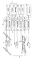
- FIG. 1 is a schematic block diagram of an X-ray inspection apparatus according to an embodiment of the present invention. It is a figure for demonstrating the structure of the X-ray inspection apparatus of FIG. It is a flowchart for demonstrating the flow of the teaching process in the X-ray inspection apparatus of FIG.
- FIG. 4 is a flowchart for explaining “image registration processing (S114)” and “image expansion / contraction / superposition processing (S116)” shown in FIG. 3; It is a conceptual diagram for demonstrating alignment with the visible light image of the front side of a board
- FIG. 1 It is a figure which shows the example of a display which superimposed and displayed the visible light image (back side) and the X-ray transmissive image. It is a figure which shows the flow of the X-ray inspection in the X-ray inspection apparatus of FIG. 1 in a flowchart format. It is a figure for demonstrating the quality determination based on the solder area in a binarized image. It is a conceptual diagram for demonstrating the other structural example of a X-ray inspection apparatus.
- the same parts are denoted by the same reference numerals. Their names and functions are also the same. Therefore, detailed description thereof will not be repeated. Further, in this specification, the X axis, the Y axis, and the Z axis are axes that are orthogonal to each other.
- FIG. 1 is a schematic block diagram of an X-ray inspection apparatus 100 according to the present embodiment.
- the X-ray inspection apparatus 100 includes an X-ray source 10 that outputs X-rays 18, an X-ray detector 23, an image acquisition control mechanism 30, and an inspection target drive mechanism 110 that moves the position of the inspection target 1. Furthermore, the X-ray inspection apparatus 100 includes an input unit 40, an output unit 50, an X-ray source control mechanism 60, a displacement meter 114, an optical camera 116 (not shown), an inspection target position control mechanism 120, an arithmetic operation. Unit 70 and storage unit 90.
- the X-ray inspection apparatus 100 is based on CAD (Computer Aided Design) data and the like, the model number of the electronic component mounted on the board to be inspected, the placement position of the part itself on the board, the placement direction, the size of the part, And an inspection object database (hereinafter referred to as “inspection object DB”) 200 for storing information related to the arrangement of electrode pads for soldering in the substrate (that is, the arrangement of soldered positions).
- CAD Computer Aided Design
- the inspection object 1 is disposed between the X-ray source 10 and the X-ray detector 23.
- the inspection object 1 is a circuit board on which components are mounted.
- the X-ray source 10, the inspection object 1, and the X-ray detector 23 are installed in order from the bottom, but from the viewpoint of maintainability of the X-ray source, the X-ray detector 23, These may be arranged in a line with the inspection object 1 and the X-ray source 10.
- the X-ray source 10 is controlled by the X-ray source control mechanism 60 and irradiates the inspection object 1 with the X-ray 18.
- the inspection target 1 is a board on which circuit components are mounted.
- the X-ray source 10 can be a scanning X-ray source capable of moving the focal position on the target in accordance with external control.
- the inspection object 1 is moved by the inspection object driving mechanism 110.
- a specific configuration of the inspection target drive mechanism 110 will be described later.
- the inspection target position control mechanism 120 controls the operation of the inspection target drive mechanism 110 based on an instruction from the calculation unit 70.
- the X-ray detector 23 is a two-dimensional X-ray detector that detects and images the X-ray output from the X-ray source 10 and transmitted through the inspection object 1.
- I.I. I. An (Image Intensifier) tube or an FPD (Flat Panel Detector) can be used. From the viewpoint of installation space, it is desirable to use FPD for the X-ray detector 23.
- the X-ray detector 23 is preferably highly sensitive so that it can be used for in-line inspection, and is particularly preferably a direct conversion FPD using CdTe.
- the image acquisition control mechanism 30 includes a detector drive control mechanism 32 and an image data acquisition unit 34.
- the detector drive control mechanism 32 controls the operation of the X-ray detector drive unit 22 and moves the X-ray detector 23 based on an instruction from the calculation unit 70.
- the image data acquisition unit 34 acquires the image data of the X-ray detector 23 specified from the calculation unit 70.
- the input unit 40 is an operation input device for receiving an instruction input from the user.
- the output unit 50 is a device that outputs measurement results and the like to the outside.
- the output unit 50 is a display for displaying an X-ray image or the like configured by the calculation unit 70.
- the user can execute various inputs via the input unit 40, and various calculation results obtained by the processing of the calculation unit 70 are displayed on the output unit 50.
- the image displayed on the output unit 50 is used for teaching processing described later, may be output for visual judgment by the user, or may be output by a quality judgment unit 78 described later. It may be output as a pass / fail judgment result.
- the X-ray source control mechanism 60 includes an electron beam control unit 62 that controls the output of the electron beam.
- the electron beam control unit 62 receives an X-ray focal position and X-ray energy (tube voltage, tube current) designation from the calculation unit 70.
- the designated X-ray energy varies depending on the configuration of the inspection object.
- the calculation unit 70 executes a program 96 stored in the storage unit 90 to control each unit, and performs predetermined calculation processing.
- the calculation unit 70 includes an X-ray source control unit 72, an image acquisition control unit 74, a reconstruction unit 76, a quality determination unit 78, an inspection target position control unit 80, an X-ray focal position calculation unit 82, and an imaging.
- a condition setting unit 84 and an inspection information generation unit 86 are included.
- the X-ray source control unit 72 determines the X-ray focal position and X-ray energy, and sends a command to the X-ray source control mechanism 60.
- the image acquisition control unit 74 sends a command to the image acquisition control mechanism 30 so that the X-ray detector 23 acquires an image. Further, the image acquisition control unit 74 acquires image data from the image acquisition control mechanism 30.
- the reconstruction unit 76 reconstructs three-dimensional data from a plurality of image data acquired by the image acquisition control unit 74.
- the pass / fail judgment unit 78 obtains the height of the board surface (board height) on which the component is mounted, and judges pass / fail of the inspection object based on the tomographic image of the board height. In addition, since the algorithm for determining pass / fail or the input information to the algorithm varies depending on the inspection target, the pass / fail determination unit 78 obtains them from the imaging condition information 94.
- the inspection target position control unit 80 controls the inspection target drive mechanism 110 via the inspection target position control mechanism 120.
- the X-ray focal position calculation unit 82 calculates an X-ray focal position, an irradiation angle, and the like for the inspection area when inspecting an inspection area where the inspection object 1 is present.
- the imaging condition setting unit 84 sets conditions (for example, applied voltage to the X-ray source, imaging time, etc.) when outputting X-rays from the X-ray source 10 according to the inspection object 1.
- the storage unit 90 includes X-ray focal position information 92, imaging condition information 94, a program 96 for realizing each function executed by the arithmetic unit 70, and image data 98 captured by the X-ray detector 23. including.
- the X-ray focal position information 92 includes the X-ray focal position calculated by the X-ray focal position calculator 82.
- the imaging condition information 94 includes information regarding the imaging conditions set by the imaging condition setting unit 84 and an algorithm for determining pass / fail.
- the storage unit 90 and the inspection target DB 200 may be anything that can accumulate data.
- the storage unit 90 includes, for example, a storage device such as a RAM (Random Access Memory), an EEPROM (Electrically Erasable and Programmable Read-Only Memory), and an HDD (Hard Disc Drive).
- the inspection target DB 200 may be an HDD or a storage device provided in another computer connected via a network.
- FIG. 2 is a diagram for explaining the configuration of the X-ray inspection apparatus 100 according to the present embodiment.
- FIG. 2 the same parts as those in FIG. Also, in FIG. 2, among the parts shown in FIG. 1, the parts necessary for explanation are extracted and directly related to the control of the X-ray focal point position, the control of the X-ray detector position, the control of the inspection target position, etc. is doing.
- the X-ray source 10 is assumed to be a cone beam type radiation source.
- the X-ray source 10 may be a scanning X-ray source capable of scanning a position (X-ray focal position) where X-rays are generated in a specified direction.
- the X-ray source 10 generates X-rays according to a command from the calculation unit 70 that has passed through the X-ray source control mechanism 60.
- the X-ray source 10 is a sealed X-ray source, and is installed on the top or bottom of the X-ray inspection apparatus 100.
- the target of the X-ray source 10 may be a transmissive type or a reflective type.
- the X-ray source 10 is attached to an operating part (not shown) and is movable in the vertical direction.
- the X-ray detector 23 is disposed at a position facing the X-ray source 10 so as to sandwich the inspection object 1 (substrate).
- the X-ray detector 23 images the X-rays emitted from the X-ray source 10.
- the X-ray detector 23 is attached to the X-ray detector driving unit 22.
- the X-ray detector driving unit 22 is a three-dimensional stage, and can move the X-ray detector 23 in the horizontal direction and the vertical direction.
- the inspection target drive mechanism 110 is installed between the X-ray source 10 and the X-ray detector 23.
- the inspection object driving mechanism 110 includes stages 111a and 111b and substrate rails 112a and 112b attached to the stages 111a and 111b.
- the stages 111a and 111b are capable of translating the inspection object 1 in the horizontal direction.
- the board rails 112a and 112b each fix the board by sandwiching the inspection object 1 from above and below.
- the operations of the stages 111a and 111b and the substrate rails 112a and 112b are controlled by the substrate drive control mechanism 126.
- the X-ray inspection apparatus 100 includes a displacement meter 114 and an optical camera 116 (this is not shown in FIG. 1).
- the displacement meter 114 measures the distance to the substrate. Therefore, the displacement meter 114 can measure the warpage of the substrate, which will be described in detail later.
- the optical camera 116 images the substrate with visible light.
- the optical camera 116 is used for photographing a fiducial mark for setting a position to be inspected.
- the displacement meter 114 and the optical camera 116 are retracted to an area where X-rays are not irradiated by a retracting mechanism (not shown) so as not to be exposed to X-rays during imaging with X-rays.
- the illumination device 115 is attached to the optical camera 116 by an attachment mechanism (not shown).
- the illumination device 115 uniformly lights the entire field of view (imaging area) of the optical camera 116.
- the illumination device 115 is a ring-shaped LED (Light Emitting Diode) light source that emits white light, but is not limited thereto, and may be another light source.
- the optical camera 116 is not necessarily provided integrally, and may be provided independently of the optical camera 116.
- the illumination device 115 is also retracted to an area where X-rays are not irradiated by a retracting mechanism (not shown) so as not to be exposed to X-rays when imaging with X-rays.
- the X-ray inspection apparatus 100 can change the ratio (magnification ratio) of the distance between the source-substrate and the distance between the source-detector. As a result, the X-ray inspection apparatus 100 can change the size (and therefore the resolution) of the inspection object 1 imaged by the X-ray detector 23.
- the X-ray inspection apparatus 100 can operate the substrate and the X-ray detector 23 so that the substrate can be imaged from various directions.
- three-dimensional data of the inspection object 1 is generated using a three-dimensional data generation technique called CT (Computed Tomography) based on the imaging results from various directions.
- the X-ray inspection apparatus 100 is used for in-line inspection.
- the inspection object driving mechanism 110 further includes a mechanism for carrying in and out the substrate.
- a substrate carrying / unloading mechanism is not shown in FIG.
- a substrate carry-in / out mechanism a belt conveyor disposed on a substrate rail is generally used.
- a rod called a pusher may be used as the carry-in / out mechanism.
- substrate can be moved by sliding a board
- the calculation unit 70 a general central processing unit (CPU) can be used.
- the storage unit 90 includes a main storage unit 90a and an auxiliary storage unit 90b.
- a memory can be used as the main storage unit 90a
- an HDD hard disk drive
- a general computer can be used as the calculation unit 70 and the storage unit 90.
- the X-ray inspection apparatus 100 can input information for teaching (teaching) the inspection position or the like in the inspection object 1 in advance regarding the inspection of the inspection object 1.
- the contents of the process of inputting such information (teaching process) will be described with reference to FIG. 3 which is a flowchart of the process.
- the teaching process is realized by the inspection information generation unit 86 in the X-ray inspection apparatus 100.
- Information relating to the teaching of the inspection generated in the teaching process is stored in the storage unit 90 as, for example, imaging condition information 94.
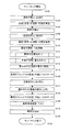
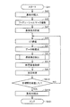
- FIG. 3 is a flowchart for explaining the flow of teaching processing in the present embodiment.
- the X-ray inspection apparatus 100 captures a visible light image with the optical camera 116 with the substrate facing down (S104). Thereafter, the substrate is once taken out of the driving range in which a visible light image can be taken (S106), the direction is reversed by a predetermined reversing mechanism (not shown in FIGS. 1 and 2), and the substrate is again mounted. It is carried in a face-up state (S108), and a visible light image is taken by the optical camera 116 in a state on the front side of the substrate (S112).
- an X-ray image is taken with the substrate facing up (S112).
- the control of the arithmetic unit 70 of the X-ray inspection apparatus 100 controls these three images.
- Position alignment is executed (S114), and further image expansion / contraction (magnification change) and overlay processing are executed (S116).
- the superimposed image is displayed on the output unit 50 under the control of the calculation unit 70 (S118).
- the display is performed from an image in which a visible light image on the front side and an X-ray image are superimposed.
- the position of the inspection object (here, solder ball) of the component mounted on the front side is further superimposed on the superimposed image as described above.
- a mark to be displayed for example, a rectangular mark is also displayed.
- the user determines whether the position of such a mark is appropriate as an inspection area (referred to as “inspection window”) based on the display, and if it is appropriate, a confirmation input for confirming the inspection window. To do. On the other hand, if it is not appropriate, for example, the position and direction of the inspection window are manually moved to a position / direction determined to be appropriate, and then confirmation input is performed.
- the arithmetic unit 70 stores, as setting information, the relative position of the inspection window with respect to the inspection target component on the front side as the imaging condition information in the storage unit 90.
- an inspection window is set in the storage unit 90 as a relative position with respect to a predetermined reference point of the component (such as a predetermined corner portion of the external shape of the component) (S120).
- the output from the output unit 50 is switched to display on the back side (S122), and a superimposed image is displayed on the back side (S124) in the same manner as the front side (S124).
- a mark inspection window
- the position of the inspection target here, solder ball
- the user determines whether or not the position of such a mark is appropriate as the inspection window based on the display, and if it is appropriate, performs a confirmation input for confirming the inspection window.
- the arithmetic unit 70 stores, as setting information, the relative position of the inspection window with respect to the back inspection target component as the imaging condition information in the storage unit 90. Also in this case, for example, although not particularly limited, an inspection window is set in the storage unit 90 as a relative position with respect to a predetermined reference point of the component (such as a predetermined corner portion of the external shape of the component) (S126). .
- the inspection standard as described later is set by the user, and a test for confirming the operation by obtaining the inspection result on a trial basis is executed (S128). Further, the substrate is unloaded (S130), and the teaching process is completed (S130).
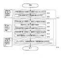
- FIG. 4 is a flowchart for explaining the “image alignment processing (S114)” and “image expansion / contraction / superposition processing (S116)” shown in FIG.
- the optical magnification of the optical camera and the X-ray camera (the configuration for taking an X-ray image by the X-ray detector 23 is referred to as “X-ray camera” for the sake of convenience) is assembling and assembling. Sometimes it is set to a specified value. As performance of the optical camera and the X-ray camera, for example, the following values are assumed.
- Optical camera Resolution: 22 ⁇ m
- X-ray camera Resolution: Variable 10, 15, 20, 25, 30 ⁇ m
- the resolution of the X-ray camera used for setting the teaching window is 20 ⁇ m. That is, the resolutions of the optical camera and the X-ray camera do not necessarily match.
- the position on the front image taken by the optical camera and the position on the image taken by the corresponding X-ray camera are calibrated so that they match. To do.
- the image of the optical camera is enlarged to match the resolution of the X-ray camera of 20 ⁇ m. Note that it may be necessary to reduce the image of the optical camera because of the resolution between the two.
- the following magnification enlargement is executed based on the image center of the visible light image (front side) (S200).
- a fiducial mark can be used as a reference for such an overlay position.
- the fiducial mark is formed of a copper wiring pattern at the diagonal end of the substrate. Therefore, the device position can be uniquely defined for the copper wiring pattern on the printed circuit board without being affected by the shape of the board or the offset of the wiring forming position with respect to the board.
- the position of a predetermined fiducial mark (for example, the corner of the upper left substrate on the front side of the substrate) is detected from the image of the visible light image (front side) (S204).
- the position A on the image of “the corner of the substrate” is stored in the storage unit 90 (S206).
- the image enlargement process is executed in the same manner as the front side with reference to the image center of the visible light image (back side) (S210).
- the position of a predetermined fiducial mark (for example, the corner of the substrate on the upper left side of the substrate back side) is detected from the image of the visible light image (the back side) (S212).
- the difference ( ⁇ (x, y)) from the position A on the image of “the corner of the substrate” is stored in the storage unit 90 (S212).
- the visible light image (back side) and the X-ray image are shifted by ⁇ (x, y), and the two are superimposed (S214).
- the position of the inspection window is specified by aligning the visible light image and the X-ray image with reference to the corner of the substrate in the visible light image on the surface. Since the specified position is registered as a coordinate relative to the part, even if registered in this way, this is a reference coordinate for the part (coordinate based on the fiducial mark). It will be registered.
- the part number, the coordinates (X, Y) of the part center, and the rotation angle ⁇ of the part are registered for each part mounted on the printed circuit board.
- the inspection window is an area of the solder to be inspected, and is registered for each part number (for each type of part).
- the fiducial mark is photographed and the substrate height is measured after the substrate is loaded. Since the substrate height is measured, when the X-ray image is a CT image (reconstructed image), a cross section of a predetermined height is displayed from the measured substrate height, so that the solder portion of the surface is displayed. An image can be displayed. If the X-ray image is a reconstructed image (CT image) based on information on the substrate height and the substrate thickness, [(measured substrate height) ⁇ (substrate thickness) ⁇ (predetermined height)] By displaying the cross section, the image of the solder portion on the back surface can be displayed.
- CT image reconstructed image
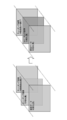
- FIG. 5 is a conceptual diagram for explaining the alignment of the visible light image on the front side, the visible light image on the back side, and the X-ray image as described above.
- the relative position of the optical camera and the X-ray camera is determined by measuring and setting the offset value at the time of manufacturing and assembly. It is assumed that the position on the image photographed by the corresponding X-ray camera has been calibrated so that both coincide with each other.
- the visible light image (front side) is used as a reference, the position of the visible light image (back side) is aligned, and the visible light image (front side) and the X-ray image are replaced with each other. Because there is no, there will be a natural position.
- the X-ray image may be a single X-ray transmission image or a reconstructed image (CT image) reconstructed from a plurality of X-ray transmission images obtained by imaging the same portion from a plurality of directions.
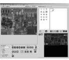
- FIG. 6 shows the transmittance of the optical image (percentage of transmission when displaying the superimposed X-ray image so that it can be seen through the visible light image) when the visible light image and the X-ray image are superimposed and displayed. It is an example of the screen to set.
- the inspection target when the visible light image and the X-ray image are superimposed and displayed is displayed.
- the visibility of the area is improved.
- buttons and the like in FIG. 6 are as follows.
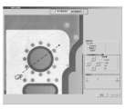
- FIG. 7 is a diagram showing a display example in which a visible light image (front side) and an X-ray reconstructed image are superimposed and displayed.
- a visible light image (front side) photographed from the upper surface on the front side and a planar image of an X-ray reconstruction image in a direction parallel to the substrate and at a specified height from the substrate surface are superimposed.
- a reconstructed image showing a designated cross section in the planar image of the X-ray reconstructed image is also displayed.
- the image displayed by superimposing the visible light image (front side) photographed from the upper surface on the front side and the planar image of the X-ray reconstructed image it is used for soldering on the substrate (front side) based on the CAD data.
- the position of the electrode pad (land) is displayed in a rectangular shape. Note that a rectangular window (inspection window) is automatically displayed on the “camera image” screen for preset parts. If there is no setting in advance, it may be set manually by the user.
- the user performs confirmation input (for example, click of the save button) after adjusting the position of the rectangular shape as necessary.
- the same image display and position adjustment are performed in advance on the visible light image (back side) and the X-ray reconstructed image. It should be noted that the display of the X-ray reconstructed image is also switched to match the display direction in accordance with the switching between the front and back display.
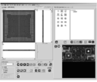
- FIG. 8 is a diagram showing a display example for further reducing the image shown in FIG. 7 and confirming the soldering position of the entire semiconductor chip.
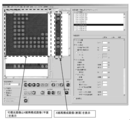
- FIG. 9 is a diagram showing a display example in which a visible light image (back side) and a part number are displayed in an overlapping manner.
- FIG. 10 is a diagram showing a display example in which a visible light image (back side) and an X-ray transmission image are superimposed and displayed.
- the display of the X-ray transmission image is switched to match the display direction according to the switching of the front and back display.
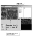
- FIG. 11 is a diagram showing a display example in which a visible light image (back side) and an X-ray transmission image are superimposed and displayed as in FIG.
- FIG. 11 a visible light image (front side) photographed from the upper surface on the front side and an X-ray transmission image are superimposed and displayed in the electrode pad for soldering on the substrate (front side) based on CAD data.
- the position of (land) is displayed in a rectangular shape.
- the user performs confirmation input (for example, click of the save button) after adjusting the position of the rectangular shape as necessary.
- the visible light image and the X-ray image can be overlaid and the display position can be confirmed with respect to the image.
- the presence of the X-ray image makes the soldered region visible to the user and confirms the coincidence with the position of the soldering electrode pad (land) on the substrate based on the CAD data.
- FIG. 12 is a flowchart showing the flow of X-ray inspection according to the present embodiment. With reference to FIG. 12, the flow of the whole X-ray inspection according to the present embodiment will be described.
- X-ray inspection apparatus 100 carries the substrate into a prescribed position inside X-ray inspection apparatus 100 by means of inspection target drive mechanism 110 (step S1). SA3).
- the specified position is usually preferably set at the center of the X-ray inspection apparatus 100, that is, at the center of the X-ray irradiation range.
- the specified position may be a position where the X-ray detector 23 can capture an X-ray fluoroscopic image of the substrate.
- step SA5 the X-ray inspection apparatus 100 images a fiducial mark with the optical camera 116. Further, the X-ray inspection apparatus 100 corrects the substrate position, if necessary, based on the position of the fiducial mark. Specifically, the X-ray inspection apparatus 100 moves the substrate position in the same manner as when carrying in. Through these processes, the X-ray inspection apparatus 100 can recognize the deviation of the substrate position and the inclination of the substrate that occur when the substrate is carried in, and can correct the deviation and the inclination.
- step SA7 the X-ray inspection apparatus 100 uses the displacement meter 114 to measure the height of the substrate in the reconstruction area (hereinafter also referred to as the field of view).
- the X-ray inspection apparatus 100 stores the measured substrate height in the main storage unit 90a. The stored height of the substrate is used at the time of CT imaging described later.
- the X-ray inspection apparatus 100 measures the substrate height for all fields of view before performing CT imaging. Keep it. This is because the displacement meter 114 needs to be retracted so as not to be exposed during CT imaging. Thus, measuring all the substrate heights in advance can reduce the entire inspection time compared to measuring the substrate height each time CT imaging of each field of view is performed.
- the X-ray inspection apparatus 100 images one field of view from a plurality of directions within the inspection object 1.
- the X-ray inspection apparatus 100 moves the substrate and the X-ray detector 23 so as to draw a circular orbit in the horizontal direction, and images the visual field from a plurality of directions.
- the positions of the substrate and the X-ray detector 23 at the time of imaging are determined by the irradiation angle ⁇ R, the source-substrate distance (FOD), and the source-detector distance (FID).
- the substrate and the X-ray detector 23 are arranged so that the center of the visual field is imaged at the center of the X-ray detector 23.
- the trajectory of the substrate and the X-ray detector 23 may not be a circle, but may be a rectangle or a straight line.
- the number of images can be set by the user. It is preferable that the user determines the number of images to be captured based on the required accuracy of reconstruction data.
- the number of images is usually about 4 to 256. However, the number of captured images is not limited to this. For example, the X-ray inspection apparatus 100 may of course capture more than 256 images.
- step SA11 the X-ray inspection apparatus 100 generates reconstruction data from captured images in a plurality of directions.
- Various methods have been proposed for the reconstruction process. For example, the Feldkamp method can be used.
- step SA13 the X-ray inspection apparatus 100 extracts the board height, that is, the height of the board surface on which the components are arranged. Details of the processing performed in step SA13 will be described later.
- step SA15 the X-ray inspection apparatus 100 acquires a tomographic image having a height away from the substrate height by a predetermined distance as an inspection image used for the inspection.
- the distance between the height of the inspection image and the substrate height is set by the user. This distance is preferably set according to the design data of the inspection object 1 and the inspection method.
- a tomographic image having a height slightly apart from the surface of the substrate on which the component is arranged to the side on which the component is arranged is set as the inspection image.
- step SA17 the X-ray inspection apparatus 100 performs visual field pass / fail determination using the inspection image. That is, the X-ray inspection apparatus 100 inspects the wettability of solder after heating, the presence or absence of solder voids and bridges, the presence or absence of foreign matter, and the like. Various quality determination methods are well known, and the X-ray inspection apparatus 100 may use a quality determination method suitable for the inspection item.
- the quality determination unit 78 determines the quality of the mounting board based on the solder area in the binarized image.
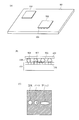
- FIG. 13 is a diagram for explaining quality determination based on the solder area in the binarized image.
- FIG. 13A is a perspective view of a substrate on which electronic components are mounted.
- a first component 502 and a second component 503 are mounted on the substrate 501.
- the second component 503 is physically and electrically connected to the substrate 501 by a BGA (Ball Grid Array) 504 or the like.
- BGA All Grid Array
- FIG. 13B is a cross-sectional view in which a connection portion between the substrate 501 and the second component 503 is cut by a cross section perpendicular to the surface of the substrate 501.
- the BGA 504 connects the second component 503 and the surface layer 505 of the substrate 501.
- the BGA 504 is heated and deforms into a state 506 after heating.
- a void 507 may occur in the state 506 after heating.
- a plurality of solder balls hereinafter also referred to as “ball terminals” may be combined to form a bridge 508.
- the X-ray inspection apparatus 100 generates three-dimensional data of an area expected to include a solder ball, and creates a tomographic image by cutting out the three-dimensional data.
- the X-ray inspection apparatus 100 binarizes the created tomographic image, and acquires a binarized image obtained by separating the image into solder and other parts.
- a general binarization process such as a discriminant analysis method can be used.
- the inspection apparatus labels the white (or 1) portion from the binarized image, and acquires a labeling image in which solder is distinguished.
- FIG. 13C is a cross-sectional view of a connection portion cut by a cross section indicated by a broken line in FIG.
- the solder is indicated by white and the parts other than the solder are indicated by oblique lines.
- three types of states, normal, void, and bridge are shown. Referring to FIG. 13C, when there is a void 507, a portion without solder is generated in the solder. When the bridge 508 is present, solder is observed in a wider area than in the normal state.
- the inspection device counts the area of each solder (the number of white or one pixel) from the labeling image to obtain the solder area.
- the inspection apparatus determines whether the solder joint surface is good or not by determining that the area is within a certain range and is non-defective, and otherwise. In general, the predetermined range of threshold values is set in advance by the user.
- step SA ⁇ b> 18 the X-ray inspection apparatus 100 determines whether or not all the visual fields have been determined to be acceptable. If there is a field of view for which pass / fail judgment has not been made (NO in step SA18), X-ray inspection apparatus 100 repeats the processing from CT imaging (step SA9). On the other hand, when the pass / fail determination is made for all the visual fields (YES in step SA18), the process proceeds to step SA19.
- step SA19 the X-ray inspection apparatus 100 carries the substrate out of the X-ray inspection apparatus 100. Specifically, the X-ray inspection apparatus 100 moves the substrate out of the X-ray inspection apparatus 100 by the inspection target drive mechanism 110.
- the X-ray inspection apparatus 100 ends the inspection for one inspection object 1 (step SA21).
- the X-ray inspection apparatus 100 repeats a series of processes from Step SA1 to Step SA21 described so far when performing inline inspection on a plurality of inspection objects 1.
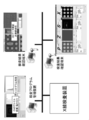
- FIG. 14 is a conceptual diagram for explaining another configuration of the X-ray inspection apparatus 100.
- the inspection target DB 200 is a configuration provided inside the X-ray inspection apparatus 100.
- the CAD data or the like does not necessarily need to be stored in the X-ray inspection apparatus 100, and is connected via a network as shown in FIG.
- the inspection object DB 200 may be stored in an external data creation device arranged outside the storage area.
- the user can inspect the inspection object (eg, solder ball) and the inspection position in order to display the inspection position by superimposing the X-ray image and the visible light image. It is possible to grasp the relationship between and the user, and there is an effect that the user can easily see.
- the inspection object eg, solder ball
- the inspection position can be determined by aligning the back surface and the back surface, and the front and back surfaces can be accurately aligned.
- inspection object 10 X-ray source, 12 substrate, 18 X-ray, 22 X-ray detector drive unit, 23 X-ray detector, 30 image acquisition control mechanism, 32 detector drive control mechanism, 34 image data acquisition unit, 40 Input unit, 50 output unit, 60 X-ray source control mechanism, 62 electron beam control unit, 70 arithmetic unit, 72 X-ray source control unit, 74 image acquisition control unit, 76 reconstruction unit, 78 pass / fail judgment unit, 80 inspection object Position control unit, 82 X-ray focal position calculation unit, 84 imaging condition setting unit, 86 inspection information generation unit, 90 storage unit, 92 X-ray focal position information, 94 imaging condition information, 96 program, 98 image data, 100 X-ray Inspection device, 110 inspection target position drive mechanism, 111a, 111b stage, 112a, 112b substrate rail, 114 displacement meter, 116 optics Mela, 120 inspection target position control mechanism.
Landscapes
- Health & Medical Sciences (AREA)
- Engineering & Computer Science (AREA)
- Nuclear Medicine, Radiotherapy & Molecular Imaging (AREA)
- Pulmonology (AREA)
- Radiology & Medical Imaging (AREA)
- Theoretical Computer Science (AREA)
- Physics & Mathematics (AREA)
- Life Sciences & Earth Sciences (AREA)
- Chemical & Material Sciences (AREA)
- Analytical Chemistry (AREA)
- Biochemistry (AREA)
- General Health & Medical Sciences (AREA)
- General Physics & Mathematics (AREA)
- Immunology (AREA)
- Pathology (AREA)
- Analysing Materials By The Use Of Radiation (AREA)
Applications Claiming Priority (2)
| Application Number | Priority Date | Filing Date | Title |
|---|---|---|---|
| JP2011-108608 | 2011-05-13 | ||
| JP2011108608A JP5830928B2 (ja) | 2011-05-13 | 2011-05-13 | 検査領域設定方法およびx線検査システム |
Publications (1)
| Publication Number | Publication Date |
|---|---|
| WO2012157467A1 true WO2012157467A1 (ja) | 2012-11-22 |
Family
ID=47176800
Family Applications (1)
| Application Number | Title | Priority Date | Filing Date |
|---|---|---|---|
| PCT/JP2012/061741 Ceased WO2012157467A1 (ja) | 2011-05-13 | 2012-05-08 | 検査領域設定方法およびx線検査システム |
Country Status (3)
| Country | Link |
|---|---|
| JP (1) | JP5830928B2 (enExample) |
| TW (1) | TW201300768A (enExample) |
| WO (1) | WO2012157467A1 (enExample) |
Cited By (2)
| Publication number | Priority date | Publication date | Assignee | Title |
|---|---|---|---|---|
| CN111094953A (zh) * | 2017-09-19 | 2020-05-01 | 柯尼卡美能达株式会社 | 非破坏检查方法 |
| US20250305971A1 (en) * | 2024-03-28 | 2025-10-02 | Tokyo Electron Limited | X-ray methods and systems for semiconductor substrate alignment |
Families Citing this family (9)
| Publication number | Priority date | Publication date | Assignee | Title |
|---|---|---|---|---|
| JP6025768B2 (ja) * | 2014-02-27 | 2016-11-16 | 三菱電機株式会社 | 貴金属量算出装置および貴金属量算出方法 |
| WO2016063380A1 (ja) * | 2014-10-22 | 2016-04-28 | 株式会社システムスクエア | 包装体の検査装置 |
| WO2016063381A1 (ja) * | 2014-10-22 | 2016-04-28 | 株式会社システムスクエア | 電磁波検知部と光学検知部を使用した検査装置 |
| JP7466362B2 (ja) * | 2020-04-13 | 2024-04-12 | 東芝Itコントロールシステム株式会社 | 非破壊検査装置 |
| JP6976613B1 (ja) * | 2020-09-24 | 2021-12-08 | 昭立電気工業株式会社 | はんだ付け作業プログラム作成システム、はんだ付け作業プログラム作成装置及びはんだ付ロボット |
| JP7753638B2 (ja) * | 2021-01-20 | 2025-10-15 | オムロン株式会社 | 計測システム、検査システム、計測装置、計測方法、検査方法、及びプログラム |
| JP2023067031A (ja) * | 2021-10-29 | 2023-05-16 | オムロン株式会社 | X線検査装置、x線検査システム、画像管理方法及びプログラム |
| JPWO2024117099A1 (enExample) * | 2022-12-01 | 2024-06-06 | ||
| WO2025177416A1 (ja) * | 2024-02-20 | 2025-08-28 | 三菱電機株式会社 | 半導体装置の製造方法および半導体検査装置 |
Citations (8)
| Publication number | Priority date | Publication date | Assignee | Title |
|---|---|---|---|---|
| JPH0252246A (ja) * | 1988-08-15 | 1990-02-21 | Tokyo Electron Ltd | X線検査装置 |
| JPH05322803A (ja) * | 1992-05-15 | 1993-12-07 | Sony Corp | X線位置合わせ確認方法、x線位置合わせ確認・位置合わせ方法、及びx線検査装置 |
| JPH11295242A (ja) * | 1998-04-10 | 1999-10-29 | Matsushita Electric Ind Co Ltd | X線基板検査装置とx線用可視光反射膜 |
| JP2002310954A (ja) * | 2001-04-18 | 2002-10-23 | Shimadzu Corp | 試料解析装置 |
| JP2004233262A (ja) * | 2003-01-31 | 2004-08-19 | Horiba Ltd | 計測結果表示方法、x線装置、及びコンピュータプログラム |
| JP2007101391A (ja) * | 2005-10-05 | 2007-04-19 | Shimadzu Corp | X線検査装置 |
| JP2009097934A (ja) * | 2007-10-15 | 2009-05-07 | Sony Corp | 断面試料作成システム及び断面試料作成方法 |
| JP2010160071A (ja) * | 2009-01-08 | 2010-07-22 | Omron Corp | X線検査方法、x線検査装置およびx線検査プログラム |
-
2011
- 2011-05-13 JP JP2011108608A patent/JP5830928B2/ja active Active
-
2012
- 2012-05-08 WO PCT/JP2012/061741 patent/WO2012157467A1/ja not_active Ceased
- 2012-05-11 TW TW101116754A patent/TW201300768A/zh unknown
Patent Citations (8)
| Publication number | Priority date | Publication date | Assignee | Title |
|---|---|---|---|---|
| JPH0252246A (ja) * | 1988-08-15 | 1990-02-21 | Tokyo Electron Ltd | X線検査装置 |
| JPH05322803A (ja) * | 1992-05-15 | 1993-12-07 | Sony Corp | X線位置合わせ確認方法、x線位置合わせ確認・位置合わせ方法、及びx線検査装置 |
| JPH11295242A (ja) * | 1998-04-10 | 1999-10-29 | Matsushita Electric Ind Co Ltd | X線基板検査装置とx線用可視光反射膜 |
| JP2002310954A (ja) * | 2001-04-18 | 2002-10-23 | Shimadzu Corp | 試料解析装置 |
| JP2004233262A (ja) * | 2003-01-31 | 2004-08-19 | Horiba Ltd | 計測結果表示方法、x線装置、及びコンピュータプログラム |
| JP2007101391A (ja) * | 2005-10-05 | 2007-04-19 | Shimadzu Corp | X線検査装置 |
| JP2009097934A (ja) * | 2007-10-15 | 2009-05-07 | Sony Corp | 断面試料作成システム及び断面試料作成方法 |
| JP2010160071A (ja) * | 2009-01-08 | 2010-07-22 | Omron Corp | X線検査方法、x線検査装置およびx線検査プログラム |
Cited By (2)
| Publication number | Priority date | Publication date | Assignee | Title |
|---|---|---|---|---|
| CN111094953A (zh) * | 2017-09-19 | 2020-05-01 | 柯尼卡美能达株式会社 | 非破坏检查方法 |
| US20250305971A1 (en) * | 2024-03-28 | 2025-10-02 | Tokyo Electron Limited | X-ray methods and systems for semiconductor substrate alignment |
Also Published As
| Publication number | Publication date |
|---|---|
| JP5830928B2 (ja) | 2015-12-09 |
| JP2012237729A (ja) | 2012-12-06 |
| TW201300768A (zh) | 2013-01-01 |
Similar Documents
| Publication | Publication Date | Title |
|---|---|---|
| JP5830928B2 (ja) | 検査領域設定方法およびx線検査システム | |
| JP5493360B2 (ja) | X線検査方法、x線検査装置およびx線検査プログラム | |
| JP5444718B2 (ja) | 検査方法、検査装置および検査用プログラム | |
| US9442080B2 (en) | Method and apparatus for generating a three-dimensional model of a region of interest using an imaging system | |
| CN107533018B (zh) | X射线检查装置、x射线检查方法及构造物的制造方法 | |
| JP5246187B2 (ja) | X線検査装置、x線検査方法およびプログラム | |
| US10054432B2 (en) | X-ray inspection apparatus and control method | |
| JP5104962B2 (ja) | X線検査方法およびx線検査装置 | |
| CN101839871B (zh) | 一种x射线分层摄影检测方法与系统 | |
| US20110081070A1 (en) | Process and Apparatus for Image Processing and Computer-readable Medium Storing Image Processing Program | |
| KR102786722B1 (ko) | 엑스레이에 기초하여 집적회로를 검색하기 위한 시스템 및 방법 | |
| JP2010145359A (ja) | X線検査装置、x線検査方法およびx線検査プログラム | |
| JP4228773B2 (ja) | 基板検査装置 | |
| JP5569061B2 (ja) | X線検査方法、x線検査装置およびx線検査プログラム | |
| JP6676023B2 (ja) | 検査位置の特定方法及び検査装置 | |
| JP4449596B2 (ja) | 実装基板検査装置 | |
| JP3902017B2 (ja) | 半田高さ計測装置およびその方法 | |
| KR0171690B1 (ko) | 단층 및 투시 검사장치 및 검사방법 | |
| KR100300586B1 (ko) | X-ray를이용한인쇄회로기판의단층검사장치및검사방법 | |
| JPS6361155A (ja) | 内部欠陥検査方法及びその装置 | |
| KR101447968B1 (ko) | 기판 검사를 위한 기준평면 설정방법 및 기준평면을 이용한 기판 검사방법 |
Legal Events
| Date | Code | Title | Description |
|---|---|---|---|
| 121 | Ep: the epo has been informed by wipo that ep was designated in this application |
Ref document number: 12785873 Country of ref document: EP Kind code of ref document: A1 |
|
| NENP | Non-entry into the national phase |
Ref country code: DE |
|
| 122 | Ep: pct application non-entry in european phase |
Ref document number: 12785873 Country of ref document: EP Kind code of ref document: A1 |