WO2012144280A1 - 車両用駆動装置 - Google Patents
車両用駆動装置 Download PDFInfo
- Publication number
- WO2012144280A1 WO2012144280A1 PCT/JP2012/056558 JP2012056558W WO2012144280A1 WO 2012144280 A1 WO2012144280 A1 WO 2012144280A1 JP 2012056558 W JP2012056558 W JP 2012056558W WO 2012144280 A1 WO2012144280 A1 WO 2012144280A1
- Authority
- WO
- WIPO (PCT)
- Prior art keywords
- rotation
- electrical machine
- output
- rotating electrical
- input
- Prior art date
- Legal status (The legal status is an assumption and is not a legal conclusion. Google has not performed a legal analysis and makes no representation as to the accuracy of the status listed.)
- Ceased
Links
Images






Classifications
-
- B—PERFORMING OPERATIONS; TRANSPORTING
- B60—VEHICLES IN GENERAL
- B60K—ARRANGEMENT OR MOUNTING OF PROPULSION UNITS OR OF TRANSMISSIONS IN VEHICLES; ARRANGEMENT OR MOUNTING OF PLURAL DIVERSE PRIME-MOVERS IN VEHICLES; AUXILIARY DRIVES FOR VEHICLES; INSTRUMENTATION OR DASHBOARDS FOR VEHICLES; ARRANGEMENTS IN CONNECTION WITH COOLING, AIR INTAKE, GAS EXHAUST OR FUEL SUPPLY OF PROPULSION UNITS IN VEHICLES
- B60K6/00—Arrangement or mounting of plural diverse prime-movers for mutual or common propulsion, e.g. hybrid propulsion systems comprising electric motors and internal combustion engines
- B60K6/20—Arrangement or mounting of plural diverse prime-movers for mutual or common propulsion, e.g. hybrid propulsion systems comprising electric motors and internal combustion engines the prime-movers consisting of electric motors and internal combustion engines, e.g. HEVs
- B60K6/22—Arrangement or mounting of plural diverse prime-movers for mutual or common propulsion, e.g. hybrid propulsion systems comprising electric motors and internal combustion engines the prime-movers consisting of electric motors and internal combustion engines, e.g. HEVs characterised by apparatus, components or means specially adapted for HEVs
- B60K6/38—Arrangement or mounting of plural diverse prime-movers for mutual or common propulsion, e.g. hybrid propulsion systems comprising electric motors and internal combustion engines the prime-movers consisting of electric motors and internal combustion engines, e.g. HEVs characterised by apparatus, components or means specially adapted for HEVs characterised by the driveline clutches
- B60K6/383—One-way clutches or freewheel devices
-
- B—PERFORMING OPERATIONS; TRANSPORTING
- B60—VEHICLES IN GENERAL
- B60W—CONJOINT CONTROL OF VEHICLE SUB-UNITS OF DIFFERENT TYPE OR DIFFERENT FUNCTION; CONTROL SYSTEMS SPECIALLY ADAPTED FOR HYBRID VEHICLES; ROAD VEHICLE DRIVE CONTROL SYSTEMS FOR PURPOSES NOT RELATED TO THE CONTROL OF A PARTICULAR SUB-UNIT
- B60W20/00—Control systems specially adapted for hybrid vehicles
- B60W20/50—Control strategies for responding to system failures, e.g. for fault diagnosis, failsafe operation or limp mode
-
- B—PERFORMING OPERATIONS; TRANSPORTING
- B60—VEHICLES IN GENERAL
- B60K—ARRANGEMENT OR MOUNTING OF PROPULSION UNITS OR OF TRANSMISSIONS IN VEHICLES; ARRANGEMENT OR MOUNTING OF PLURAL DIVERSE PRIME-MOVERS IN VEHICLES; AUXILIARY DRIVES FOR VEHICLES; INSTRUMENTATION OR DASHBOARDS FOR VEHICLES; ARRANGEMENTS IN CONNECTION WITH COOLING, AIR INTAKE, GAS EXHAUST OR FUEL SUPPLY OF PROPULSION UNITS IN VEHICLES
- B60K6/00—Arrangement or mounting of plural diverse prime-movers for mutual or common propulsion, e.g. hybrid propulsion systems comprising electric motors and internal combustion engines
- B60K6/20—Arrangement or mounting of plural diverse prime-movers for mutual or common propulsion, e.g. hybrid propulsion systems comprising electric motors and internal combustion engines the prime-movers consisting of electric motors and internal combustion engines, e.g. HEVs
- B60K6/22—Arrangement or mounting of plural diverse prime-movers for mutual or common propulsion, e.g. hybrid propulsion systems comprising electric motors and internal combustion engines the prime-movers consisting of electric motors and internal combustion engines, e.g. HEVs characterised by apparatus, components or means specially adapted for HEVs
- B60K6/38—Arrangement or mounting of plural diverse prime-movers for mutual or common propulsion, e.g. hybrid propulsion systems comprising electric motors and internal combustion engines the prime-movers consisting of electric motors and internal combustion engines, e.g. HEVs characterised by apparatus, components or means specially adapted for HEVs characterised by the driveline clutches
- B60K6/387—Actuated clutches, i.e. clutches engaged or disengaged by electric, hydraulic or mechanical actuating means
-
- B—PERFORMING OPERATIONS; TRANSPORTING
- B60—VEHICLES IN GENERAL
- B60K—ARRANGEMENT OR MOUNTING OF PROPULSION UNITS OR OF TRANSMISSIONS IN VEHICLES; ARRANGEMENT OR MOUNTING OF PLURAL DIVERSE PRIME-MOVERS IN VEHICLES; AUXILIARY DRIVES FOR VEHICLES; INSTRUMENTATION OR DASHBOARDS FOR VEHICLES; ARRANGEMENTS IN CONNECTION WITH COOLING, AIR INTAKE, GAS EXHAUST OR FUEL SUPPLY OF PROPULSION UNITS IN VEHICLES
- B60K6/00—Arrangement or mounting of plural diverse prime-movers for mutual or common propulsion, e.g. hybrid propulsion systems comprising electric motors and internal combustion engines
- B60K6/20—Arrangement or mounting of plural diverse prime-movers for mutual or common propulsion, e.g. hybrid propulsion systems comprising electric motors and internal combustion engines the prime-movers consisting of electric motors and internal combustion engines, e.g. HEVs
- B60K6/42—Arrangement or mounting of plural diverse prime-movers for mutual or common propulsion, e.g. hybrid propulsion systems comprising electric motors and internal combustion engines the prime-movers consisting of electric motors and internal combustion engines, e.g. HEVs characterised by the architecture of the hybrid electric vehicle
- B60K6/44—Series-parallel type
- B60K6/445—Differential gearing distribution type
-
- B—PERFORMING OPERATIONS; TRANSPORTING
- B60—VEHICLES IN GENERAL
- B60L—PROPULSION OF ELECTRICALLY-PROPELLED VEHICLES; SUPPLYING ELECTRIC POWER FOR AUXILIARY EQUIPMENT OF ELECTRICALLY-PROPELLED VEHICLES; ELECTRODYNAMIC BRAKE SYSTEMS FOR VEHICLES IN GENERAL; MAGNETIC SUSPENSION OR LEVITATION FOR VEHICLES; MONITORING OPERATING VARIABLES OF ELECTRICALLY-PROPELLED VEHICLES; ELECTRIC SAFETY DEVICES FOR ELECTRICALLY-PROPELLED VEHICLES
- B60L15/00—Methods, circuits, or devices for controlling the traction-motor speed of electrically-propelled vehicles
- B60L15/20—Methods, circuits, or devices for controlling the traction-motor speed of electrically-propelled vehicles for control of the vehicle or its driving motor to achieve a desired performance, e.g. speed, torque, programmed variation of speed
-
- B—PERFORMING OPERATIONS; TRANSPORTING
- B60—VEHICLES IN GENERAL
- B60L—PROPULSION OF ELECTRICALLY-PROPELLED VEHICLES; SUPPLYING ELECTRIC POWER FOR AUXILIARY EQUIPMENT OF ELECTRICALLY-PROPELLED VEHICLES; ELECTRODYNAMIC BRAKE SYSTEMS FOR VEHICLES IN GENERAL; MAGNETIC SUSPENSION OR LEVITATION FOR VEHICLES; MONITORING OPERATING VARIABLES OF ELECTRICALLY-PROPELLED VEHICLES; ELECTRIC SAFETY DEVICES FOR ELECTRICALLY-PROPELLED VEHICLES
- B60L3/00—Electric devices on electrically-propelled vehicles for safety purposes; Monitoring operating variables, e.g. speed, deceleration or energy consumption
- B60L3/0023—Detecting, eliminating, remedying or compensating for drive train abnormalities, e.g. failures within the drive train
-
- B—PERFORMING OPERATIONS; TRANSPORTING
- B60—VEHICLES IN GENERAL
- B60L—PROPULSION OF ELECTRICALLY-PROPELLED VEHICLES; SUPPLYING ELECTRIC POWER FOR AUXILIARY EQUIPMENT OF ELECTRICALLY-PROPELLED VEHICLES; ELECTRODYNAMIC BRAKE SYSTEMS FOR VEHICLES IN GENERAL; MAGNETIC SUSPENSION OR LEVITATION FOR VEHICLES; MONITORING OPERATING VARIABLES OF ELECTRICALLY-PROPELLED VEHICLES; ELECTRIC SAFETY DEVICES FOR ELECTRICALLY-PROPELLED VEHICLES
- B60L50/00—Electric propulsion with power supplied within the vehicle
- B60L50/10—Electric propulsion with power supplied within the vehicle using propulsion power supplied by engine-driven generators, e.g. generators driven by combustion engines
- B60L50/16—Electric propulsion with power supplied within the vehicle using propulsion power supplied by engine-driven generators, e.g. generators driven by combustion engines with provision for separate direct mechanical propulsion
-
- B—PERFORMING OPERATIONS; TRANSPORTING
- B60—VEHICLES IN GENERAL
- B60L—PROPULSION OF ELECTRICALLY-PROPELLED VEHICLES; SUPPLYING ELECTRIC POWER FOR AUXILIARY EQUIPMENT OF ELECTRICALLY-PROPELLED VEHICLES; ELECTRODYNAMIC BRAKE SYSTEMS FOR VEHICLES IN GENERAL; MAGNETIC SUSPENSION OR LEVITATION FOR VEHICLES; MONITORING OPERATING VARIABLES OF ELECTRICALLY-PROPELLED VEHICLES; ELECTRIC SAFETY DEVICES FOR ELECTRICALLY-PROPELLED VEHICLES
- B60L50/00—Electric propulsion with power supplied within the vehicle
- B60L50/40—Electric propulsion with power supplied within the vehicle using propulsion power supplied by capacitors
-
- B—PERFORMING OPERATIONS; TRANSPORTING
- B60—VEHICLES IN GENERAL
- B60L—PROPULSION OF ELECTRICALLY-PROPELLED VEHICLES; SUPPLYING ELECTRIC POWER FOR AUXILIARY EQUIPMENT OF ELECTRICALLY-PROPELLED VEHICLES; ELECTRODYNAMIC BRAKE SYSTEMS FOR VEHICLES IN GENERAL; MAGNETIC SUSPENSION OR LEVITATION FOR VEHICLES; MONITORING OPERATING VARIABLES OF ELECTRICALLY-PROPELLED VEHICLES; ELECTRIC SAFETY DEVICES FOR ELECTRICALLY-PROPELLED VEHICLES
- B60L50/00—Electric propulsion with power supplied within the vehicle
- B60L50/50—Electric propulsion with power supplied within the vehicle using propulsion power supplied by batteries or fuel cells
- B60L50/60—Electric propulsion with power supplied within the vehicle using propulsion power supplied by batteries or fuel cells using power supplied by batteries
- B60L50/61—Electric propulsion with power supplied within the vehicle using propulsion power supplied by batteries or fuel cells using power supplied by batteries by batteries charged by engine-driven generators, e.g. series hybrid electric vehicles
-
- B—PERFORMING OPERATIONS; TRANSPORTING
- B60—VEHICLES IN GENERAL
- B60W—CONJOINT CONTROL OF VEHICLE SUB-UNITS OF DIFFERENT TYPE OR DIFFERENT FUNCTION; CONTROL SYSTEMS SPECIALLY ADAPTED FOR HYBRID VEHICLES; ROAD VEHICLE DRIVE CONTROL SYSTEMS FOR PURPOSES NOT RELATED TO THE CONTROL OF A PARTICULAR SUB-UNIT
- B60W10/00—Conjoint control of vehicle sub-units of different type or different function
- B60W10/04—Conjoint control of vehicle sub-units of different type or different function including control of propulsion units
- B60W10/06—Conjoint control of vehicle sub-units of different type or different function including control of propulsion units including control of combustion engines
-
- B—PERFORMING OPERATIONS; TRANSPORTING
- B60—VEHICLES IN GENERAL
- B60W—CONJOINT CONTROL OF VEHICLE SUB-UNITS OF DIFFERENT TYPE OR DIFFERENT FUNCTION; CONTROL SYSTEMS SPECIALLY ADAPTED FOR HYBRID VEHICLES; ROAD VEHICLE DRIVE CONTROL SYSTEMS FOR PURPOSES NOT RELATED TO THE CONTROL OF A PARTICULAR SUB-UNIT
- B60W10/00—Conjoint control of vehicle sub-units of different type or different function
- B60W10/04—Conjoint control of vehicle sub-units of different type or different function including control of propulsion units
- B60W10/08—Conjoint control of vehicle sub-units of different type or different function including control of propulsion units including control of electric propulsion units, e.g. motors or generators
-
- B—PERFORMING OPERATIONS; TRANSPORTING
- B60—VEHICLES IN GENERAL
- B60W—CONJOINT CONTROL OF VEHICLE SUB-UNITS OF DIFFERENT TYPE OR DIFFERENT FUNCTION; CONTROL SYSTEMS SPECIALLY ADAPTED FOR HYBRID VEHICLES; ROAD VEHICLE DRIVE CONTROL SYSTEMS FOR PURPOSES NOT RELATED TO THE CONTROL OF A PARTICULAR SUB-UNIT
- B60W20/00—Control systems specially adapted for hybrid vehicles
-
- B—PERFORMING OPERATIONS; TRANSPORTING
- B60—VEHICLES IN GENERAL
- B60W—CONJOINT CONTROL OF VEHICLE SUB-UNITS OF DIFFERENT TYPE OR DIFFERENT FUNCTION; CONTROL SYSTEMS SPECIALLY ADAPTED FOR HYBRID VEHICLES; ROAD VEHICLE DRIVE CONTROL SYSTEMS FOR PURPOSES NOT RELATED TO THE CONTROL OF A PARTICULAR SUB-UNIT
- B60W30/00—Purposes of road vehicle drive control systems not related to the control of a particular sub-unit, e.g. of systems using conjoint control of vehicle sub-units
- B60W30/18—Propelling the vehicle
- B60W30/184—Preventing damage resulting from overload or excessive wear of the driveline
- B60W30/1846—Preventing of breakage of drive line components, e.g. parts of the gearing
-
- B—PERFORMING OPERATIONS; TRANSPORTING
- B60—VEHICLES IN GENERAL
- B60L—PROPULSION OF ELECTRICALLY-PROPELLED VEHICLES; SUPPLYING ELECTRIC POWER FOR AUXILIARY EQUIPMENT OF ELECTRICALLY-PROPELLED VEHICLES; ELECTRODYNAMIC BRAKE SYSTEMS FOR VEHICLES IN GENERAL; MAGNETIC SUSPENSION OR LEVITATION FOR VEHICLES; MONITORING OPERATING VARIABLES OF ELECTRICALLY-PROPELLED VEHICLES; ELECTRIC SAFETY DEVICES FOR ELECTRICALLY-PROPELLED VEHICLES
- B60L2210/00—Converter types
- B60L2210/40—DC to AC converters
-
- B—PERFORMING OPERATIONS; TRANSPORTING
- B60—VEHICLES IN GENERAL
- B60L—PROPULSION OF ELECTRICALLY-PROPELLED VEHICLES; SUPPLYING ELECTRIC POWER FOR AUXILIARY EQUIPMENT OF ELECTRICALLY-PROPELLED VEHICLES; ELECTRODYNAMIC BRAKE SYSTEMS FOR VEHICLES IN GENERAL; MAGNETIC SUSPENSION OR LEVITATION FOR VEHICLES; MONITORING OPERATING VARIABLES OF ELECTRICALLY-PROPELLED VEHICLES; ELECTRIC SAFETY DEVICES FOR ELECTRICALLY-PROPELLED VEHICLES
- B60L2240/00—Control parameters of input or output; Target parameters
- B60L2240/40—Drive Train control parameters
- B60L2240/42—Drive Train control parameters related to electric machines
- B60L2240/421—Speed
-
- B—PERFORMING OPERATIONS; TRANSPORTING
- B60—VEHICLES IN GENERAL
- B60L—PROPULSION OF ELECTRICALLY-PROPELLED VEHICLES; SUPPLYING ELECTRIC POWER FOR AUXILIARY EQUIPMENT OF ELECTRICALLY-PROPELLED VEHICLES; ELECTRODYNAMIC BRAKE SYSTEMS FOR VEHICLES IN GENERAL; MAGNETIC SUSPENSION OR LEVITATION FOR VEHICLES; MONITORING OPERATING VARIABLES OF ELECTRICALLY-PROPELLED VEHICLES; ELECTRIC SAFETY DEVICES FOR ELECTRICALLY-PROPELLED VEHICLES
- B60L2240/00—Control parameters of input or output; Target parameters
- B60L2240/40—Drive Train control parameters
- B60L2240/42—Drive Train control parameters related to electric machines
- B60L2240/423—Torque
-
- B—PERFORMING OPERATIONS; TRANSPORTING
- B60—VEHICLES IN GENERAL
- B60L—PROPULSION OF ELECTRICALLY-PROPELLED VEHICLES; SUPPLYING ELECTRIC POWER FOR AUXILIARY EQUIPMENT OF ELECTRICALLY-PROPELLED VEHICLES; ELECTRODYNAMIC BRAKE SYSTEMS FOR VEHICLES IN GENERAL; MAGNETIC SUSPENSION OR LEVITATION FOR VEHICLES; MONITORING OPERATING VARIABLES OF ELECTRICALLY-PROPELLED VEHICLES; ELECTRIC SAFETY DEVICES FOR ELECTRICALLY-PROPELLED VEHICLES
- B60L2240/00—Control parameters of input or output; Target parameters
- B60L2240/40—Drive Train control parameters
- B60L2240/50—Drive Train control parameters related to clutches
- B60L2240/507—Operating parameters
-
- B—PERFORMING OPERATIONS; TRANSPORTING
- B60—VEHICLES IN GENERAL
- B60W—CONJOINT CONTROL OF VEHICLE SUB-UNITS OF DIFFERENT TYPE OR DIFFERENT FUNCTION; CONTROL SYSTEMS SPECIALLY ADAPTED FOR HYBRID VEHICLES; ROAD VEHICLE DRIVE CONTROL SYSTEMS FOR PURPOSES NOT RELATED TO THE CONTROL OF A PARTICULAR SUB-UNIT
- B60W2510/00—Input parameters relating to a particular sub-units
- B60W2510/10—Change speed gearings
- B60W2510/104—Output speed
- B60W2510/1045—Output speed change rate
-
- B—PERFORMING OPERATIONS; TRANSPORTING
- B60—VEHICLES IN GENERAL
- B60W—CONJOINT CONTROL OF VEHICLE SUB-UNITS OF DIFFERENT TYPE OR DIFFERENT FUNCTION; CONTROL SYSTEMS SPECIALLY ADAPTED FOR HYBRID VEHICLES; ROAD VEHICLE DRIVE CONTROL SYSTEMS FOR PURPOSES NOT RELATED TO THE CONTROL OF A PARTICULAR SUB-UNIT
- B60W2710/00—Output or target parameters relating to a particular sub-units
- B60W2710/06—Combustion engines, Gas turbines
- B60W2710/0644—Engine speed
-
- B—PERFORMING OPERATIONS; TRANSPORTING
- B60—VEHICLES IN GENERAL
- B60W—CONJOINT CONTROL OF VEHICLE SUB-UNITS OF DIFFERENT TYPE OR DIFFERENT FUNCTION; CONTROL SYSTEMS SPECIALLY ADAPTED FOR HYBRID VEHICLES; ROAD VEHICLE DRIVE CONTROL SYSTEMS FOR PURPOSES NOT RELATED TO THE CONTROL OF A PARTICULAR SUB-UNIT
- B60W2710/00—Output or target parameters relating to a particular sub-units
- B60W2710/08—Electric propulsion units
- B60W2710/081—Speed
-
- Y—GENERAL TAGGING OF NEW TECHNOLOGICAL DEVELOPMENTS; GENERAL TAGGING OF CROSS-SECTIONAL TECHNOLOGIES SPANNING OVER SEVERAL SECTIONS OF THE IPC; TECHNICAL SUBJECTS COVERED BY FORMER USPC CROSS-REFERENCE ART COLLECTIONS [XRACs] AND DIGESTS
- Y02—TECHNOLOGIES OR APPLICATIONS FOR MITIGATION OR ADAPTATION AGAINST CLIMATE CHANGE
- Y02T—CLIMATE CHANGE MITIGATION TECHNOLOGIES RELATED TO TRANSPORTATION
- Y02T10/00—Road transport of goods or passengers
- Y02T10/60—Other road transportation technologies with climate change mitigation effect
- Y02T10/62—Hybrid vehicles
-
- Y—GENERAL TAGGING OF NEW TECHNOLOGICAL DEVELOPMENTS; GENERAL TAGGING OF CROSS-SECTIONAL TECHNOLOGIES SPANNING OVER SEVERAL SECTIONS OF THE IPC; TECHNICAL SUBJECTS COVERED BY FORMER USPC CROSS-REFERENCE ART COLLECTIONS [XRACs] AND DIGESTS
- Y02—TECHNOLOGIES OR APPLICATIONS FOR MITIGATION OR ADAPTATION AGAINST CLIMATE CHANGE
- Y02T—CLIMATE CHANGE MITIGATION TECHNOLOGIES RELATED TO TRANSPORTATION
- Y02T10/00—Road transport of goods or passengers
- Y02T10/60—Other road transportation technologies with climate change mitigation effect
- Y02T10/64—Electric machine technologies in electromobility
-
- Y—GENERAL TAGGING OF NEW TECHNOLOGICAL DEVELOPMENTS; GENERAL TAGGING OF CROSS-SECTIONAL TECHNOLOGIES SPANNING OVER SEVERAL SECTIONS OF THE IPC; TECHNICAL SUBJECTS COVERED BY FORMER USPC CROSS-REFERENCE ART COLLECTIONS [XRACs] AND DIGESTS
- Y02—TECHNOLOGIES OR APPLICATIONS FOR MITIGATION OR ADAPTATION AGAINST CLIMATE CHANGE
- Y02T—CLIMATE CHANGE MITIGATION TECHNOLOGIES RELATED TO TRANSPORTATION
- Y02T10/00—Road transport of goods or passengers
- Y02T10/60—Other road transportation technologies with climate change mitigation effect
- Y02T10/70—Energy storage systems for electromobility, e.g. batteries
-
- Y—GENERAL TAGGING OF NEW TECHNOLOGICAL DEVELOPMENTS; GENERAL TAGGING OF CROSS-SECTIONAL TECHNOLOGIES SPANNING OVER SEVERAL SECTIONS OF THE IPC; TECHNICAL SUBJECTS COVERED BY FORMER USPC CROSS-REFERENCE ART COLLECTIONS [XRACs] AND DIGESTS
- Y02—TECHNOLOGIES OR APPLICATIONS FOR MITIGATION OR ADAPTATION AGAINST CLIMATE CHANGE
- Y02T—CLIMATE CHANGE MITIGATION TECHNOLOGIES RELATED TO TRANSPORTATION
- Y02T10/00—Road transport of goods or passengers
- Y02T10/60—Other road transportation technologies with climate change mitigation effect
- Y02T10/7072—Electromobility specific charging systems or methods for batteries, ultracapacitors, supercapacitors or double-layer capacitors
-
- Y—GENERAL TAGGING OF NEW TECHNOLOGICAL DEVELOPMENTS; GENERAL TAGGING OF CROSS-SECTIONAL TECHNOLOGIES SPANNING OVER SEVERAL SECTIONS OF THE IPC; TECHNICAL SUBJECTS COVERED BY FORMER USPC CROSS-REFERENCE ART COLLECTIONS [XRACs] AND DIGESTS
- Y02—TECHNOLOGIES OR APPLICATIONS FOR MITIGATION OR ADAPTATION AGAINST CLIMATE CHANGE
- Y02T—CLIMATE CHANGE MITIGATION TECHNOLOGIES RELATED TO TRANSPORTATION
- Y02T10/00—Road transport of goods or passengers
- Y02T10/60—Other road transportation technologies with climate change mitigation effect
- Y02T10/72—Electric energy management in electromobility
Definitions
- the present invention includes an input member drivingly connected to an internal combustion engine, an output member drivingly connected to a wheel, a first rotating electrical machine, a second rotating electrical machine, and a differential gear device having at least three rotating elements, And a vehicle drive device including the control device.
- Patent Document 1 a differential gear device is configured by a planetary gear mechanism having three rotating elements, a first rotating electrical machine is drivingly connected to a sun gear, an input member is drivingly connected to a carrier, and a second rotating electrical machine is connected to a ring gear. And the structure by which the output member was drive-connected was described.
- the vehicle drive device includes a one-way clutch that restricts negative rotation of the carrier and the input member that are drivingly connected so as to rotate integrally, and the one-way clutch in a state where negative rotation of the carrier and the input member is restricted.
- Has a travel mode in which the vehicle travels by receiving the reaction force of the torque of the first rotating electrical machine and transmitting the torque of the first rotating electrical machine to the output member.
- the control device is configured to perform failure determination of the one-way clutch based on the detected value of the rotational speed of the internal combustion engine.
- Patent Document 1 is only for determining a failure of the one-way clutch, and does not prevent a possible failure.
- a shock absorbing mechanism such as a damper or a torque limiter separately.
- such measures increase the manufacturing cost of the device and increase the weight.
- a control device wherein the first rotating electrical machine, the input member, and the output member are respectively connected to different rotating elements of the differential gear device.
- the differential gear is driven and connected without any other rotating element
- the second rotating electric machine is a rotating element to which the first rotating electric machine is drivingly connected and the input rotating element other than the input rotating element to which the input member is drivingly connected.
- a one-way clutch that is connected to the rotating element of the device without any other rotating element of the differential gear device and restricts negative rotation of the input rotating element, and the control device includes the output member Rotation A rotation change detector that detects an output rotation sudden change state in which the absolute value of the speed is equal to or greater than a predetermined value, and the output rotation sudden change state in a low rotation state in which the rotation speed of the input rotation element is less than a predetermined control threshold value.
- a restriction avoidance control unit that executes restriction avoidance control for controlling the rotation speed of the first rotating electrical machine so that the rotation speed of the input rotation element is equal to or higher than the control threshold when the rotation is detected.
- driving connection refers to a state where two rotating elements are connected so as to be able to transmit a driving force, and the two rotating elements are connected so as to rotate integrally, or the two
- the rotating element is used as a concept including a state in which the driving force is connected to be transmitted through one or more transmission members.
- a transmission member include various members that transmit rotation at the same speed or a variable speed, and include, for example, a shaft, a gear mechanism, a belt, a chain, and the like.
- an engagement element that selectively transmits rotation and driving force for example, a friction engagement element, a meshing engagement element, or the like may be included.
- driving force is used synonymously with “torque”.
- a differential gear mechanism having three rotating elements such as a planetary gear mechanism having a sun gear, a carrier, and a ring gear is used, and the differential gear mechanism alone or a plurality of differential gear mechanisms are used.
- a device obtained by combining them is called a “differential gear device”.
- the “rotary electric machine” is used as a concept including a motor (electric motor), a generator (generator), and a motor / generator functioning as both a motor and a generator as necessary.
- the regulation avoidance control when the vehicle is traveling in a low rotation state in which the rotation speed of the input rotation element is less than a predetermined control threshold value, the rotation acceleration that is the time change rate of the rotation speed of the output member When it is detected that the output suddenly changes in the positive direction or the negative direction by a predetermined value or more and the output rotation suddenly changes, the regulation avoidance control is executed.
- the regulation avoidance control by controlling the rotational speed of the first rotating electrical machine, the rotational speed of the input rotational element of the differential gear device is set to be equal to or higher than the control threshold value. A rotating state can be reliably realized.
- the rotation speed of the input rotation element can be suppressed to zero and negative rotation restriction by the one-way clutch can be suppressed, and the one-way clutch It can suppress that big load is applied to. Therefore, the occurrence of the one-way clutch failure can be effectively suppressed beforehand. Further, in the above characteristic configuration, the occurrence of the one-way clutch failure can be effectively suppressed by executing the regulation avoidance control, so that the strength of the one-way clutch itself is designed high, the damper, the torque limiter, etc. There is no need to provide a separate shock absorbing mechanism. Therefore, an increase in manufacturing cost and an increase in weight can be suppressed. Therefore, it is possible to realize a vehicle drive device that can effectively suppress the occurrence of a one-way clutch failure while suppressing an increase in manufacturing cost and an increase in weight.
- control threshold value is a value equal to or greater than the amount of fluctuation in the negative direction of the rotation speed of the input rotation element in the output rotation sudden change state.
- target rotational speed data prescribing a relationship between the rotational speed of the output member and the target rotational speed of the first rotating electrical machine for setting the rotational speed of the input rotational element to be equal to or higher than the control threshold value is provided in advance
- the restriction avoidance control unit determines a target rotational speed of the first rotating electrical machine based on the target rotational speed data and an actual rotational speed of the output member, and performs the first rotation so as to match the target rotational speed. It is preferable that the rotation speed of the electric machine be controlled.
- the target rotational speed of the first rotating electrical machine can be simply set according to the vehicle speed based on the target rotational speed data that preliminarily defines the relationship between the rotational speed of the output member and the target rotational speed of the first rotating electrical machine. Can be determined appropriately. Then, by controlling the rotation speed of the first rotating electrical machine so as to coincide with the determined target rotation speed, the rotation speed of the input rotation element can be reliably set to be equal to or higher than the control threshold value. Therefore, it can suppress more reliably that a big load is applied to a one-way clutch.
- the restriction avoidance control unit determines a target rotation speed of the first rotating electrical machine based on an actual rotation speed of the output member, the control threshold value, and a gear ratio of the differential gear device. And it is suitable if it is set as the structure which controls the rotational speed of said 1st rotary electric machine so that it may correspond to the said target rotational speed.
- the target rotational speed of the first rotating electrical machine can be appropriately determined by calculation according to the vehicle speed based on the relationship between the control threshold value and the gear ratio of the differential gear device. Then, by controlling the rotation speed of the first rotating electrical machine so as to coincide with the determined target rotation speed, the rotation speed of the input rotation element can be reliably set to be equal to or higher than the control threshold value. Therefore, it can suppress more reliably that a big load is applied to a one-way clutch.
- the rotation change detection unit has a predetermined sudden change threshold value in which the rotation acceleration of the output member is set to a value larger in the negative direction than the rotation acceleration of the output member according to the vehicle deceleration acceleration during vehicle braking. It is preferable that the output rotation sudden change state is detected by detecting the above.
- the rotation change detection unit is configured to detect the output rotation sudden change state by detecting the activation of the antilock brake system of the vehicle.
- the regulation avoidance control unit It is preferable that the restriction avoidance control is terminated.
- the vehicle state is stable and a new output rotation sudden change occurs.
- the possibility of becoming a state is considered low. According to the above configuration, it is possible to prevent the regulation avoidance control from being continued more than necessary, and to appropriately control the first rotating electrical machine and the like according to the situation.
- the order of the rotational speeds of at least three rotating elements of the differential gear device is the order of the rotating element to which the first rotating electrical machine is drivingly connected, the input rotating element, and the rotating element to which the output member is drivingly connected. It is preferable that the configuration is as follows.
- the “rotation speed order” is either the order from the high speed side to the low speed side or the order from the low speed side to the high speed side, and can be either depending on the rotation state of each differential gear mechanism.
- the order of the rotating elements does not change. That is, “in order of rotational speed” means “in order of increasing or decreasing rotational speed in the rotational state of each rotating element”.
- the “order of rotational speed” is the same as the order of arrangement in the speed diagram (collinear diagram) of each rotating element.
- “arrangement order of speed elements in the speed diagram (collinear diagram)” is the order in which the axes corresponding to the respective speed elements are arranged in the speed diagram.
- the rotation speed of the input rotation element is zero, and the low rotation state is always less than the control threshold value. For this reason, if the rotational acceleration of the output member suddenly decreases during traveling in the second electric traveling mode, there is a risk that a load is immediately applied to the input rotating element.
- the application object of the present invention includes the above-described configuration.
- a vehicle drive device that can realize the second electric travel mode is particularly suitable.
- a friction engagement device capable of releasing the drive connection between the input member and the input rotation element connected to the one-way clutch.
- the input rotation element and the input member drivingly connected to the internal combustion engine can be separated. Therefore, when the regulation avoidance control is executed, the rotational speed of the first rotating electrical machine can be controlled in a state where there is no frictional resistance inside the internal combustion engine, and the rotational speed of the input rotational element becomes higher than the control threshold value. Time can be shortened. Therefore, it can suppress more reliably that a big load is applied to a one-way clutch. Further, in this configuration, when it is possible to realize an electric travel mode in which the vehicle is driven by using the driving force of the second rotating electrical machine in a state where the combustion of the internal combustion engine is stopped, friction is caused when the vehicle travels in the electric travel mode. The internal combustion engine can be disconnected from the wheel by releasing the engagement device. Therefore, energy efficiency in the electric travel mode can be improved.
- the vehicle drive device 1 drives a vehicle (hybrid vehicle) that includes both the internal combustion engine E and the rotating electrical machines MG1 and MG2 as driving force sources for the wheels W.
- a driving device (a driving device for a hybrid vehicle) is used.
- the vehicle drive device 1 which concerns on this embodiment is provided with the control apparatus 70 (refer FIG. 2), and this control apparatus 70 controls operation
- a broken line indicates a power transmission path
- a solid arrow indicates a transmission path for various information.
- the differential gear device DG provided in the vehicle drive device 1 is constituted by a planetary gear mechanism PG having a sun gear s, a carrier ca, and a ring gear r as rotating elements.
- the first rotating electrical machine MG1 is drivingly connected to the sun gear s
- the input member I is drivingly connected to the carrier ca
- the second rotating electrical machine MG2 and the ring gear r are not connected to the other rotating elements of the planetary gear mechanism PG.
- the output member O is drivingly connected.
- the input member I is drivingly connected to the internal combustion engine E
- the output member O is drivingly connected to the wheels W.
- the vehicle drive device 1 includes a friction engagement device CL that can release the drive connection between the input member I and the carrier ca, and a one-way clutch F that restricts negative rotation of the carrier ca. Yes.
- the internal combustion engine E can be disconnected when executing the electric travel mode in which the output torque of the second rotating electrical machine MG2 is transmitted to the output member O and the wheels W are driven while the internal combustion engine E is stopped. It is possible to improve the energy efficiency by avoiding idling (dragging) of the first rotating electrical machine MG1. Further, when the torque for driving the wheel W is insufficient with only the output torque of the second rotating electrical machine MG2, the output torque of the first rotating electrical machine MG1 is output to the output member O in the negative rotation restricted state of the one-way clutch F. It is possible to realize a traveling mode (second electric traveling mode which is a kind of electric traveling mode) that transmits and assists driving of the wheels W.
- the vehicle drive device 1 according to the present embodiment is configured to be able to execute restriction avoidance control so as to suppress a failure of the one-way clutch F that may occur under a specific situation. It is characterized by a point.
- restriction avoidance control so as to suppress a failure of the one-way clutch F that may occur under a specific situation. It is characterized by a point.
- the vehicle drive device 1 includes an input member I that is drivingly connected to the internal combustion engine E, an output member O that is drivingly connected to the wheels W, a first rotating electrical machine MG1, a second rotating electrical machine MG2, and at least three rotations.
- a differential gear device DG having elements and a control device 70 are provided.
- the vehicle drive device 1 according to the present embodiment distributes the output torque of the internal combustion engine E to the first rotating electrical machine MG1 side and the wheels W and the second rotating electrical machine MG2 side. It is configured as a drive device for a so-called two-motor split type hybrid vehicle including the device DG.
- the differential gear device DG is constituted by a single pinion type planetary gear mechanism PG. That is, the differential gear device DG has three rotating elements, specifically, a sun gear s, a carrier ca, and a ring gear r in this example. Then, as described below, the input member I, the output member O, and the first rotating electrical machine MG1 are respectively connected to different rotating elements of the differential gear device DG via other rotating elements of the differential gear device DG. It is connected without driving. In this example, the first rotating electrical machine MG1 is drivingly connected to the sun gear s, the input member I is drivingly connected to the carrier ca, and the output member O is drivingly connected to the ring gear r.
- the rotation element to which the input member I is drivingly connected is “input rotation element Ei”
- the rotation element to which the output member O is drivingly connected is “output rotation element Eo”
- the rotation to which the first rotating electrical machine MG1 is drivingly connected is “first rotating electrical machine connecting element Em”
- the sun gear s is the first rotating electrical machine connecting element Em
- the carrier ca is the input rotating element Ei
- the ring gear r is the output rotating element Eo.
- the rotational speeds of the three rotating elements of the differential gear device DG are in the order of the sun gear s, the carrier ca, and the ring gear r (see FIG. 3 and the like).
- the rotational speeds of the three rotating elements of the differential gear device DG are in the order of the first rotating electrical machine connecting element Em, the input rotating element Ei, and the output rotating element Eo.
- the second rotating electrical machine MG2 is a rotating element of the differential gear device DG other than the input rotating element Ei (carrier ca) and the first rotating electrical machine connecting element Em (sun gear s) (in this example, the ring gear r that is the output rotating element Eo). )
- the vehicle drive device 1 includes a friction engagement device CL capable of releasing the drive connection between the input member I and the input rotation element Ei (carrier ca).
- the vehicle drive device 1 includes a one-way clutch F that restricts negative rotation of the input rotation element Ei (carrier ca).
- a connecting member that rotates integrally with the rotating element is connected to each rotating element of the differential gear device DG.
- a first connecting member 41 is connected to the sun gear s
- a second connecting member 42 is connected to the carrier ca
- a third connecting member 43 is connected to the ring gear r.
- Each of the input member I, the output member O, the first rotating electrical machine MG1 and the second rotating electrical machine MG2 is drivingly connected to any one of these connecting members 41, 42, and 43, so that the differential gear device.
- the input member I is drivingly connected to the internal combustion engine E.
- the input member I is a shaft member (input shaft).
- the internal combustion engine E is a prime mover that outputs power by combustion of fuel.
- a spark ignition engine such as a gasoline engine or a compression ignition engine such as a diesel engine can be used.
- the input member I is drivingly connected to an output shaft of an internal combustion engine such as a crankshaft of the internal combustion engine E.
- the input member I is drivingly connected so as to rotate integrally with the output shaft of the internal combustion engine, and the rotational speed of the input member I becomes equal to the rotational speed of the internal combustion engine E.
- the internal combustion engine E is drivingly connected to the input member I via another device such as a damper or a flywheel.
- the output member O is drivingly connected to the wheel W.
- the output member O is a gear member, and specifically, a differential input gear provided in the output differential gear device D.
- the output differential gear device D is configured by a differential gear mechanism using a plurality of bevel gears that mesh with each other, and the torque transmitted to the output member O is applied to the left and right wheels W that serve as drive wheels.
- a vehicle wheel W on which the vehicle drive device 1 is mounted is provided with a brake device 8 (for example, a disc brake or the like) that operates in conjunction with a brake operation. Braking is performed.
- the first rotating electrical machine MG1 includes a first stator St1 fixed to the case CS, and a first rotor Ro1 that is rotatably supported on the radially inner side of the first stator St1.
- the first rotor Ro1 rotates integrally with the first rotating electrical machine connecting element Em (in this example, the sun gear s) via the first connecting member 41 as the first rotor shaft to which the first rotor Ro1 is fixed.
- the second rotating electrical machine MG2 includes a second stator St2 fixed to the case CS, and a second rotor Ro2 that is rotatably supported on the radially inner side of the second stator St2.
- the second rotor Ro2 is drivingly connected to rotate integrally with the second rotating electrical machine output gear 55 via a second rotor shaft to which the second rotor Ro2 is fixed.
- the first rotating electrical machine MG1 is electrically connected to the power storage device B via the first inverter 4, and the second rotating electrical machine MG2 is connected to the power storage device B via the second inverter 5. Is electrically connected.
- the power storage device B a battery, a capacitor, or the like can be used.
- each of the first rotating electrical machine MG1 and the second rotating electrical machine MG2 has a function as a motor (electric motor) that receives power supplied from the power storage device B and generates power (torque), It is possible to function as a generator (generator) that receives the supply to generate electric power and supplies the generated electric power to the power storage device B.
- the friction engagement device CL is provided so as to selectively drive and connect the input member I and the second connecting member 42. That is, the friction engagement device CL is provided on a power transmission path between the input member I and the input rotation element Ei (in this example, the carrier ca) of the differential gear device DG, and the input member I and the input rotation element Ei. It is possible to release the drive connection. In other words, the input member I is selectively drivingly connected to the input rotation element Ei via the friction engagement device CL.
- the friction engagement device CL is in the direct coupling engagement state, the rotation speed of the second connecting member 42 that rotates integrally with the input rotation element Ei is equal to the rotation speed of the input member I (internal combustion engine E).
- the friction engagement device CL when the friction engagement device CL is in the released state, the input rotation element Ei and the second connecting member 42 and the input member I are in a relative rotation state.
- the friction engagement device CL is configured as a wet multi-plate clutch that operates by hydraulic pressure.
- the one-way clutch F is provided between the case CS and the second connecting member 42 so as to allow relative rotation of the input rotation element Ei (carrier ca in this example) with respect to the case CS only in the positive direction.
- the case CS is a non-rotating member fixed to the vehicle body of the vehicle on which the vehicle drive device 1 is mounted, and its rotation speed is always zero. Therefore, in the present embodiment, the one-way clutch F allows the input rotation element Ei of the differential gear device DG to rotate positively (rotate in the positive direction) and negatively rotate (rotate in the negative direction). It is provided to regulate this.
- a state where the negative rotation of the input rotation element Ei is actually restricted is referred to as a “negative rotation restriction state”.
- a state where the rotation of the input rotation element Ei is rotating in the forward direction without being restricted is referred to as a “relative rotation state”.
- the input rotation element Ei and the second connecting member 42 that rotate integrally are fixed to the case CS and the rotation speed becomes zero.
- the second rotating electrical machine MG2 and the output member O are drivingly connected to the output rotating element Eo (ring gear r in this example) via the counter gear mechanism C.
- the counter gear mechanism C includes a first counter gear 53, a second counter gear 54, and a counter shaft that is coupled so as to rotate integrally.
- the third connecting member 43 has a counter drive gear 52 that meshes with the first counter gear 53.
- the second rotating electrical machine output gear 55 is arranged so as to mesh with the first counter gear 53 at a position different from the counter drive gear 52 in the circumferential direction (the circumferential direction of the first counter gear 53).
- the electric machine MG2 is drivingly connected to the output rotation element Eo.
- the output member O is disposed so as to mesh with the second counter gear 54, and is drivingly connected to the output rotation element Eo. That is, in the present embodiment, the rotational speed relationships among the output rotating element Eo, the second rotating electrical machine MG2 and the output member O are proportional to each other, and the proportionality coefficient (that is, the rotational speed ratio) is It becomes a value according to the number of teeth of the gear intervening.
- the vehicle drive device 1 includes a hybrid travel mode (split travel mode) in which the vehicle travels by the output torques of both the internal combustion engine E and the rotating electrical machines MG1 and MG2, and the rotating electrical machine.
- An electric travel mode (including a first electric travel mode and a second electric travel mode described later) in which the vehicle is driven only by the output torque of MG1 and MG2 is provided. These travel modes will be described later.
- the control device 70 includes a rotating electrical machine control unit 75, an engagement control unit 76, a travel mode determination unit 77, a rotation change detection unit 71, and a regulation avoidance control unit 73. Yes.
- the control device 70 includes an arithmetic processing device such as a CPU as a core, and includes a storage device such as a RAM and a ROM. Each functional unit of the control device 70 is configured by software (program) stored in a ROM or the like, hardware such as a separately provided arithmetic circuit, or both. Each of these functional units is configured to exchange information with each other.
- the control device 70 is configured to be able to acquire information from a sensor or the like provided in each part of the vehicle in order to acquire information of each part of the vehicle on which the vehicle drive device 1 is mounted. Specifically, as shown in FIG. 2, the control device 70 obtains information from the input rotation element sensor Se1, the first rotor shaft sensor Se2, the output member sensor Se3, the power storage state sensor Se10, and the accelerator opening degree sensor Se11. It is configured to be obtainable.
- the input rotation element sensor Se1 is a sensor that detects the rotation speed of the input rotation element Ei of the differential gear device DG. In this example, the rotation speed of the input rotation element Ei detected by the input rotation element sensor Se1 is equal to the rotation speed of the second connecting member 42.
- the first rotor shaft sensor Se2 is a sensor that detects the rotational speed of the first rotating electrical machine MG1 (first rotor shaft). In this example, the rotational speed of the first rotating electrical machine MG1 detected by the first rotor shaft sensor Se2 is equal to the rotational speed of the first connecting member 41 (sun gear s).
- the first rotor shaft sensor Se2 can be, for example, a rotation sensor (such as a resolver) provided in the first rotating electrical machine MG1.
- the output member sensor Se3 is a sensor that detects the rotation speed of the output member O.
- the control device 70 can derive the vehicle speed based on the rotation speed of the output member O detected by the output member sensor Se3.
- the accelerator opening sensor Se11 is a sensor that detects the accelerator opening by detecting an operation amount of an accelerator pedal (not shown).
- the power storage state sensor Se10 is a sensor that detects the state of the power storage device B (such as the amount of power storage). In the present embodiment, the power storage state sensor Se10 includes a voltage sensor, a current sensor, and the like, and detects the amount of power stored by detecting SOC (state of charge).
- the vehicle includes an internal combustion engine control unit 3 and a vehicle control unit 80.
- the internal combustion engine control unit 3 controls the operation of the internal combustion engine E by controlling each part of the internal combustion engine E.
- the internal combustion engine control unit 3 also controls the internal combustion engine start control for changing the internal combustion engine E in the combustion stop state to the start state in accordance with a command from the control device 70, or the internal combustion engine E in the start state to the combustion stop state. It is possible to perform internal combustion engine stop control that changes.
- These internal combustion engine start control and internal combustion engine stop control are appropriately executed when the travel mode is switched.
- the vehicle control unit 80 compensates for each part of the vehicle other than the drive system (for example, a braking system including the brake device 8 and the like, a steering system including a steering wheel (not shown), and a compressor and lights of an in-vehicle air conditioner.
- the vehicle running state is integratedly controlled by controlling the machinery and the like.
- the vehicle control unit 80 includes an antilock brake system (AntilocktiBrake System).
- the vehicle control unit 80 is configured to be able to acquire information from the wheel speed sensor Se12, and outputs an ABS operation command (an activation command for the antilock brake system) when the lock of the wheel W is detected. Then, the braking force of the brake device 8 is controlled so that the wheels W are not locked according to the ABS operation command.
- the rotating electric machine control unit 75 is a functional unit that performs operation control of the first rotating electric machine MG1 and the second rotating electric machine MG2. Specifically, the rotating electrical machine control unit 75 sets a target torque and a target rotational speed as control targets for the output torque and rotational speed of the first rotating electrical machine MG1, and the first rotating electrical machine MG1 is set according to the control target. The first inverter 4 is controlled so as to operate. In this example, the rotating electrical machine control unit 75 controls the operation of the first rotating electrical machine MG1 by torque control or rotational speed control.
- torque control is control which sets the target torque with respect to the 1st rotary electric machine MG1, and matches the output torque of the 1st rotary electric machine MG1 with the said target torque.
- the rotational speed control is a control for setting a target rotational speed for the first rotating electrical machine MG1 and adjusting the rotational speed of the first rotating electrical machine MG1 to the target rotational speed.
- the control for the second rotating electrical machine MG2 is the same as that for the first rotating electrical machine MG1 except that the first inverter 4 is replaced with the second inverter 5.
- the engagement control unit 76 is a functional unit that controls the state of the friction engagement device CL.
- the engagement control unit 76 controls the oil pressure supplied to the friction engagement device CL, thereby controlling the friction engagement device CL mainly in the direct engagement state or the release state.
- the “directly engaged state” is a state in which the input member I and the second connecting member 42 on both sides of the frictional engagement device CL are directly connected and rotate integrally.
- the “released state” is a state in which rotation and torque are not transmitted between the input member I and the second connecting member 42 on both sides of the friction engagement device CL.
- the engagement control unit 76 controls the state of the friction engagement device CL according to the travel mode determined by the travel mode determination unit 77.
- the engagement control unit 76 sets the friction engagement device CL in the direct engagement state when the hybrid travel mode is selected, and sets the friction engagement device CL in the released state when the electric travel mode is selected.
- the engagement control unit 76 performs “slip” in which torque is transmitted between the input member I and the second connecting member 42 in a state in which the input member I and the second connecting member 42 rotate relative to each other.
- the friction engagement device CL is controlled so as to be in the “engaged state”.
- the travel mode determination unit 77 is a functional unit that determines the travel mode of the vehicle.
- the traveling mode determination unit 77 for example, the vehicle speed derived based on the detection result of the output member sensor Se3, the accelerator opening detected by the accelerator opening sensor Se11, and the storage state detected by the storage state sensor Se10.
- the driving mode to be realized by the vehicle drive device 1 is determined based on the above.
- the travel modes that can be determined by the travel mode determination unit 77 include a hybrid travel mode and an electric travel mode.
- the electric driving mode includes a first electric driving mode and a second electric driving mode.
- the travel mode determination unit 77 is a mode that preliminarily stores the storage device 6 configured by a memory or the like and defines the relationship between the vehicle speed, the accelerator opening, and the storage state (storage amount) and the travel mode.
- a travel mode is determined with reference to a selection map (not shown).
- the hybrid travel mode is a travel mode in which the vehicle travels by the output torque of both the internal combustion engine E and the rotating electrical machines MG1, MG2.
- the hybrid travel mode according to the present embodiment is a split travel mode, in which the friction engagement device CL is in the direct engagement state, and the output torque of the internal combustion engine E transmitted via the input member I and the friction engagement device CL is It is transmitted to the output member O while being distributed to the first rotating electrical machine MG1.
- the one-way clutch F is in a relative rotation state.
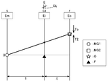
- FIG. 3 is a velocity diagram showing the operating state of the differential gear device DG in the hybrid travel mode. In each speed diagram referred to in the following description, the vertical axis corresponds to the rotational speed of each rotating element.
- each of the plurality of vertical lines arranged in parallel corresponds to each rotation element of the differential gear device DG.
- “Em”, “Ei”, and “Eo” surrounded by a rectangle described above each vertical line indicate the first rotating electrical machine connecting element Em, the input rotating element Ei, and the output rotating element Eo, respectively. ing.
- the rotational speed of the first rotating electrical machine MG1, the rotational speed of the second rotating electrical machine MG2, the rotational speed of the internal combustion engine E (input member I), and the rotational speed of the output member O are mutually different. Shown with different symbols.
- the rotational speeds of the second rotating electrical machine MG2 and the output member O are the rotational speeds after the shift by the power transmission system between them and the output rotating element Eo.
- the state where the one-way clutch F allows only the positive rotation of the input rotation element Ei (in this example, the carrier ca) and restricts the negative rotation is indicated by using a black upward triangle symbol. This is shown schematically.
- T1 indicates the output torque of the first rotating electrical machine MG1 transmitted to the first rotating electrical machine connecting element Em (sun gear s in this example), and “T2” indicates the output rotating element Eo (ring gear r in this example). 2 shows the output torque of the second rotating electrical machine MG2 transmitted to.
- Te indicates the output torque of the internal combustion engine E transmitted to the input rotation element Ei via the friction engagement device CL in the direct engagement state
- To indicates the output rotation element Eo from the output member O (wheel W).
- the running torque (running resistance) transmitted to is shown. In the arrows arranged adjacent to these torques, an upward arrow indicates a positive torque, and a downward arrow indicates a negative torque.
- the output torque of the internal combustion engine E is transmitted to the input rotation element Ei in the direct engagement state of the friction engagement device CL.
- the internal combustion engine E outputs a positive torque corresponding to the required driving force for running the vehicle while being controlled so as to be maintained in a state where the efficiency is high and the amount of exhaust gas is low (a state in accordance with the optimum fuel consumption characteristics).
- This torque is transmitted to the input rotation element Ei via the input member I.
- the torque of the internal combustion engine E is input to the input rotational element Ei that is intermediate in the order of rotational speed, and the first rotating electrical machine connection that is on the one side in the order of rotational speed with respect to the input rotational element Ei.
- the torque in the negative direction of the first rotating electrical machine MG1 is input to the element Em.
- the output member O is drivably coupled to the output rotation element Eo on the other side in the order of the rotation speed with respect to the input rotation element Ei.
- the first rotating electrical machine MG1 functions as a reaction force receiver for the torque of the internal combustion engine E, and the differential gear device DG uses a part of the torque of the internal combustion engine E transmitted to the input rotating element Ei to the first rotating electrical machine connecting element Em. Is distributed to the first rotating electrical machine MG1 that is drivingly connected to the output rotating element E0, and the torque attenuated with respect to the torque of the internal combustion engine E is transmitted to the output member O that is drivingly connected to the output rotating element Eo. As a result, the vehicle is caused to travel.
- the first rotating electrical machine MG1 basically generates power by rotating in the positive direction while outputting a torque in the negative direction.
- the second rotating electrical machine MG2 assists the torque transmitted to the output member O by outputting a positive torque as necessary.
- the first rotating electrical machine MG1 may rotate negatively while outputting torque in the negative direction, and the second rotating electrical machine MG2 may generate electric power for driving the first rotating electrical machine MG1. is there.
- the vehicle can travel while generating power using the large torque of the internal combustion engine E while driving the internal combustion engine E efficiently. Therefore, according to the mode selection map referred to by the travel mode determination unit 77, the hybrid travel mode is selected, for example, in a low power storage state where the power storage amount of the power storage device B is a predetermined value or less.
- the electric travel mode is a travel mode in which travel is performed only by the output torque of the rotating electrical machines MG1, MG2.
- the friction engagement device CL is released, and the output torque of one or both of the first rotating electrical machine MG1 and the second rotating electrical machine MG2 is transmitted to the output member O when the combustion of the internal combustion engine E is stopped.
- the electric travel mode includes two modes, a first electric travel mode and a second electric travel mode.
- the first electric travel mode is a travel mode in which travel is performed only by the output torque of the second rotating electrical machine MG2 in the released state of the friction engagement device CL and the relative rotation state of the one-way clutch F.
- the internal combustion engine E is in a combustion stopped state.
- torque transmission via the first rotating electrical machine connecting element Em and the input rotating element Ei is not performed and the driving rotation is connected to the output rotating element Eo.
- Only the torque of the second rotating electrical machine MG2 is transmitted to the output member O that is also drive-coupled to the output rotating element Eo.
- Second rotating electrical machine MG2 outputs a torque corresponding to the required driving force to drive the vehicle.
- the rotation speed of the first rotating electrical machine MG1 is substantially zero, and the idling of the first rotating electrical machine MG1 is avoided.
- the mode selection map for example, the first electric travel mode is selected in a low load state in which the power storage amount of the power storage device B is relatively large and the required driving force is a predetermined value or less.
- the second electric travel mode is a travel mode in which the vehicle is driven by at least the output torque of the first rotating electrical machine MG1 in the released state of the friction engagement device CL and the negative rotation restricted state of the one-way clutch F.
- the vehicle in the second electric traveling mode, the vehicle travels by the output torque of both the first rotating electrical machine MG1 and the second rotating electrical machine MG2.
- the internal combustion engine E is in a combustion stopped state.
- the torque of the second rotating electrical machine MG2 that is drivingly connected to the output rotating element Eo is applied to the output member O that is also drivingly connected to the output rotating element Eo. Communicated.
- the first rotating electrical machine MG1 rotates negatively while outputting a torque in the negative direction, and the rotational speed of the first rotating electrical machine connecting element Em that is drivingly connected to the first rotating electrical machine MG1 decreases while negatively rotating.
- the rotational speed of the first rotating electrical machine connecting element Em decreases, the rotational speed of the input rotating element Ei also decreases, and when it eventually becomes zero, the one-way clutch F enters the negative rotation restricting state, and the second connecting member 42
- the input rotation element Ei is fixed to the case CS.
- the one-way clutch F in the negative rotation restricted state functions as a reaction force receiver for the torque of the first rotating electrical machine MG1, and the torque in the negative direction of the first rotating electrical machine MG1 transmitted to the first rotating electrical machine connecting element Em is torque Is reversed and transmitted to the output member O that is drivingly connected to the output rotation element Eo.
- the first rotating electrical machine MG1 and the second rotating electrical machine MG2 cooperate to output a torque corresponding to the required driving force, and cause the vehicle to travel.
- the second electric travel mode since the torque of the first rotating electrical machine MG1 can be used in addition to the torque of the second rotating electrical machine MG2, a relatively large torque can be transmitted to the wheels W to travel the vehicle.
- the mode selection map for example, the second electric travel mode is selected in a high load state where the storage amount of the power storage device B is relatively large and the required driving force is a predetermined value or more.
- the input rotation element Ei is fixed to the case CS, and the torque of the first rotating electrical machine MG1 can be transmitted to the output member O.
- the friction engagement device CL may be in a direct engagement state.
- the control device 70 includes a rotation change detection unit 71 and a regulation avoidance control unit 73. In the following description, it is assumed that the vehicle is traveling in the second electric travel mode.
- the rotation change detection unit 71 is a functional unit that detects an output rotation sudden change state in which the rotation speed of the output member O is suddenly changing.
- the rotation change detection unit 71 detects an output rotation sudden change state based on one or both of the rotation acceleration of the output member O and the ABS operation command from the vehicle control unit 80.
- the rotation change detection unit 71 is configured to detect an output rotation sudden change state based on both the rotation acceleration of the output member O and the ABS operation command.
- the rotation change detection unit 71 includes a rotation acceleration calculation unit 72 in order to acquire information on the rotation acceleration of the output member O.
- the rotational acceleration calculation unit 72 sequentially acquires information on the rotational speed of the output member O detected by the output member sensor Se3 at a predetermined period, and calculates the rotational acceleration of the output member O based on the acquired information.
- the rotation acceleration of the output member O is a change amount (time change rate) per unit time of the rotation speed of the output member O.
- the rotational acceleration calculator 72 calculates the amount of change in the rotational speed of the output member O before and after a period of N (N is an integer equal to or greater than 1) period, and divides the amount of change by the time of N periods. Thus, the rotational acceleration of the output member O is calculated.
- the rotation change detection unit 71 detects an output rotation sudden change state based at least on the information of the rotation acceleration calculated by the rotation acceleration calculation unit 72.
- the rotation change detection unit 71 detects an output rotation sudden change state on condition that the rotation acceleration of the output member O is detected to be equal to or greater than a predetermined sudden change threshold value At in the negative direction.
- the rotational acceleration is greater than or equal to the sudden change threshold value At in the negative direction means that the absolute value of the rotational acceleration changes suddenly in relation to the relationship between the rotational acceleration that takes a negative value and the sudden change threshold value At. It means that it is equal to or larger than the absolute value of the threshold value At.
- the output rotation is detected on the condition that the rotation change detection unit 71 detects that the rotation acceleration of the output member O is equal to or less than the sudden change threshold value At (see FIG. 8) set to a negative value, the output rotation is detected. Detect sudden changes.
- the sudden change threshold value At serving as a detection reference for the output rotation sudden change state by the rotational change detection unit 71 is set based on the rotational acceleration of the output member O corresponding to the deceleration acceleration of the vehicle during braking of the vehicle.
- the “deceleration acceleration of the vehicle” is a deceleration acceleration (vehicle acceleration ( ⁇ 0)) of the vehicle body accompanying braking of the vehicle.
- the “rotational acceleration of the output member O in accordance with the deceleration acceleration of the vehicle” refers to the output member O when the vehicle body decelerates without the wheels W locking (while the tire maintains the gripping force) during braking of the vehicle. , Which is proportional to the vehicle acceleration.
- the rotational acceleration of the output member O corresponding to the vehicle body acceleration in the case where the vehicle is braked with a relatively large braking force close to the braking force immediately before the wheels W are locked and the tire loses the gripping force here, This is referred to as “maximum grip rotation acceleration”
- the abrupt change threshold value At is set so as to be larger in the negative direction than that. That is, the sudden change threshold value At is set to a value less than the maximum grip rotation acceleration that takes a negative value, and the absolute value of the sudden change threshold value At is larger than the absolute value of the maximum grip rotation acceleration.
- the rotation change detection unit 71 basically detects the output rotation sudden change state by detecting that the rotation acceleration of the output member O is not more than the sudden change threshold value At.
- the rotation change detection unit 71 further detects an output rotation sudden change state by detecting the issuing of the ABS operation command based on the ABS operation command from the vehicle control unit 80.
- the rotation change detection unit 71 detects the output rotation by detecting which one of the rotation acceleration of the output member O becomes the abrupt change threshold value At or less and the ABS operation command is issued, whichever comes first. Detect sudden changes.
- the rotation change detection unit 71 detects an output rotation sudden change state, the rotation change detection unit 71 outputs information on the detection result to the regulation avoidance control unit 73.
- the wheel W alternately repeats a locked state and an unlocked state, and the rotational acceleration of the output member O is a state where the rotational acceleration is not more than the sudden change threshold value At and a state where it is greater than the sudden change threshold value At. May be alternately repeated (see FIG. 8).
- the detection of the output rotation sudden change state based on the ABS operation command is limited to one time, whereas the detection of the output rotation sudden change state based on the rotational acceleration of the output member O is performed a plurality of times. Become.
- the rotation change detection unit 71 detects the output rotation sudden change state based on the rotation acceleration of the output member O after detecting the first output rotation sudden change state in a series of vehicle braking operations. The resulting information is output to the regulation avoidance control unit 73.
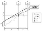
- the restriction avoidance control unit 73 has a low rotation speed at which the rotation speed of the input rotation element Ei is less than a predetermined control threshold value Nt (see FIGS. 7 and 8) set to a value greater than zero.
- Nt a predetermined control threshold value
- This is a functional unit that executes regulation avoidance control when the rotation change detection unit 71 detects an output rotation sudden change state while the vehicle is traveling in a state.
- the regulation avoidance control is control for controlling the rotation speed of the first rotating electrical machine MG1 so that the rotation speed of the input rotation element Ei is equal to or higher than the control threshold value Nt.
- the rotational speed of the first rotating electrical machine MG1 by controlling the rotational speed of the first rotating electrical machine MG1, the rotational speed of the input rotational element Ei that has been rotated at a rotational speed less than the control threshold value Nt is increased to control the threshold value.
- This control is Nt or more.
- the control threshold value Nt that is a criterion for determining the low rotation state, which is one of the starting conditions for executing the regulation avoidance control, varies in the negative direction of the rotation speed of the input rotation element Ei in the output rotation sudden change state. It is set considering the amount. More specifically, based on the predicted change amount of the rotation speed of the output member O assumed when the output rotation sudden change state occurs, the speed ratio ⁇ and the differential by the power transmission system from the output member O to the output rotation element Eo Considering also the gear ratio ⁇ of the gear unit DG (see FIGS. 3 to 7), the predicted fluctuation amount ⁇ N in the negative direction of the rotational speed of the input rotation element Ei is calculated in advance.
- the gear ratio ⁇ of the differential gear device DG is a ratio of the number of teeth of the sun gear s to the number of teeth of the ring gear r.
- the gear ratio ⁇ by the power transmission system from the output member O to the output rotation element Eo is the counter drive gear 52, the first counter gear 53, the second counter gear 54, and the output member O as a differential input gear. Determined based on the number of teeth.
- the control threshold value Nt is set by adding a predetermined margin to the predicted fluctuation amount ⁇ N. That is, the control threshold value Nt is set to a value larger than the predicted fluctuation amount ⁇ N by a predetermined amount.
- the one-way clutch F is in a negative rotation restricted state, and the rotational speed of the input rotation element Ei is zero. Therefore, during traveling in the second electric traveling mode, the rotational speed of the input rotation element Ei is always less than the control threshold value Nt, and is always in a low rotational state. In this state, when the restriction avoidance control unit 73 receives information on the detection result of the output rotation sudden change state from the rotation change detection unit 71, the restriction avoidance control is started.
- the restriction avoidance control unit 73 includes a target rotation speed determination unit 74 in order to set the target rotation speed of the first rotating electrical machine MG1 during the restriction avoidance control.
- the target rotational speed determination unit 74 refers to the target rotational speed data 6a stored and provided in advance in the storage device 6, and determines the target rotational speed of the first rotating electrical machine MG1.
- the target rotation speed data 6a defines the relationship between the rotation speed of the output member O and the target rotation speed of the first rotating electrical machine MG1 for setting the rotation speed of the input rotation element Ei to be equal to or higher than the control threshold value Nt. Data. If the gear ratio ⁇ of the differential gear unit DG and the speed ratio ⁇ by the power transmission system from the output member O to the output rotation element Eo are known, the rotation speed of the input rotation element Ei matches the control threshold value Nt. The relationship between the rotation speed of the output member O and the rotation speed of the first rotating electrical machine MG1 is determined. That is, the rotation speed of the first rotating electrical machine MG1 is determined according to the rotation speed of the output member O.
- the target rotational speed data 6a of the present embodiment a target rotational speed equal to or higher than the rotational speed of the first rotating electrical machine MG1 determined as described above is associated with each rotational speed of the output member O. Accordingly, the target rotational speed data 6a includes the rotational speed of the output member O, the speed ratio ⁇ by the power transmission system from the output member O to the output rotational element Eo, the gear ratio ⁇ of the differential gear device DG, and the control. It can be said that the target rotational speed of the first rotating electrical machine MG1 set based on the threshold value Nt is stored.
- Such target rotational speed data 6a is provided in the form of a two-dimensional map or a table.
- the target rotational speed determination unit 74 determines the target rotational speed of the first rotating electrical machine MG1 based on the target rotational speed data 6a and the rotational speed of the output member O. That is, the target rotational speed determination unit 74 acquires the rotational speed (actual rotational speed) of the output member O actually detected by the output member sensor Se3, and refers to the target rotational speed data 6a. The target rotational speed of the first rotating electrical machine MG1 associated with the actual rotational speed of the output member O is read and acquired. The target rotational speed determination unit 74 determines the target rotational speed acquired in this way as the target rotational speed of the first rotating electrical machine MG1 in the restriction avoidance control.
- the rotational speed of the output member O sequentially changes in a predetermined manner with time as the vehicle is braked (see FIG. 8). Therefore, the target rotational speed of the first rotating electrical machine MG1 is also sequentially corrected accordingly.
- the regulation avoidance control unit 73 controls the rotation speed of the first rotating electrical machine MG1 so as to match the determined target rotation speed.
- the target rotational speed determination unit 74 outputs the determined target rotational speed to the rotating electrical machine control unit 75, and the rotating electrical machine control unit 75 uses the received target rotational speed as a target value to rotate the first rotational electrical machine MG1.
- the regulation avoidance control unit 73 cooperates with the rotating electrical machine control unit 75 to control the rotational speed of the first rotating electrical machine MG1 so as to coincide with the target rotational speed determined by the target rotational speed determination unit 74.
- the regulation avoidance control unit 73 executes the rotational speed control of the first rotating electrical machine MG1 to increase the rotational speed, and as shown in FIG. 7, the rotational speed (in this example, less than the control threshold value Nt).
- the rotational speed of the input rotational element Ei that was rotating at zero rotational speed is increased to a control threshold value Nt or higher.
- the one-way clutch F enters a relative rotation state in which the second connecting member 42 rotates at a rotation speed equal to or higher than the control threshold value Nt.
- the speed diagram of the differential gear device DG immediately before the output change sudden change state is detected by the rotation change detection unit 71 is indicated by a broken line.
- the first rotating electrical machine MG1 is immediately detected by detecting the occurrence of an output rotation sudden change state before the rotational speed of the output member O is greatly reduced and executing the regulation avoidance control.
- the speed diagram of the differential gear device DG in the case where it is assumed that the rotational speed of the second gear coincides with the target rotational speed is indicated by a solid line.
- the rotation speed of the input rotation element Ei becomes equal to or higher than the control threshold value Nt by executing the regulation avoidance control.
- the friction engagement device CL is released and the input rotation element Ei is disconnected from the input member I and the internal combustion engine E.
- the rotational speed of the first rotating electrical machine MG can be increased without a load due to resistance or the like. Therefore, the state where the rotation speed of the input rotation element Ei is equal to or higher than the control threshold value Nt can be realized at an early stage.
- the strength of the one-way clutch F itself is designed to be high, or a shock absorbing mechanism such as a damper or a torque limiter is provided separately. There is no need to Therefore, an increase in manufacturing cost and weight of the vehicle drive device 1 can be suppressed.
- the restriction avoidance control unit 73 determines the end of restriction avoidance control based on a predetermined end determination time Tt (see FIG. 8) set in advance. In the present embodiment, the regulation avoidance control unit 73 does not detect a new output rotation sudden change state until a predetermined end determination time Tt elapses after the rotation change detection unit 71 detects the output rotation sudden change state. Then, the end of the regulation avoidance control is determined. Specifically, when the regulation avoidance control unit 73 receives the information of the detection result of the output rotation sudden change state from the rotation change detection unit 71, the regulation avoidance control unit 73 measures the elapsed time from that time by a timer or the like.
- the restriction avoidance control unit 73 determines the end of the restriction avoidance control.
- the rotating electrical machine control unit 75 controls the first rotating electrical machine MG1 and the second rotating electrical machine MG2 according to the control target in the normal second electric travel mode.
- FIG. 9 is a flowchart showing the entire processing procedure of the specific traveling control
- FIG. 10 is a flowchart showing the processing procedure of the regulation avoidance control in step # 05.
- the restriction avoidance control unit 73 determines whether or not the rotation speed of the input rotation element Ei is a low rotation state that is less than a predetermined control threshold value Nt (step # 01).
- the one-way clutch F is in the negative rotation restriction state, and the rotation speed of the input rotation element Ei is zero, so it is determined that it is in the low rotation state (step # 01: Yes)
- the rotational acceleration calculation unit 72 acquires information on the rotational speed of the output member O from the output member sensor Se3 (step # 02).
- the rotational acceleration calculation unit 72 sequentially acquires information on the rotational speed of the output member O at a predetermined period, and calculates the rotational acceleration of the output member O (step # 03).
- the rotation change detection unit 71 receives information on the rotation acceleration of the output member O, and compares the received rotation acceleration with a predetermined sudden change threshold value At to determine whether or not an output rotation sudden change state has occurred. judge. At that time, the rotation change detection unit 71 determines whether or not the output rotation sudden change state has occurred based on the ABS operation command from the vehicle control unit 80 (step # 04). If the output rotation sudden change state is not detected (step # 04: No), the specific travel control is terminated as it is. On the other hand, at time T01 in FIG.
- the rotational speed of the output member O suddenly decreases due to, for example, the locking of the wheels W, and the rotational acceleration becomes less than the sudden change threshold value At (the absolute value of the rotational acceleration of the output member O is When it is detected that the sudden change threshold value At has become larger than the absolute value of the sudden change threshold value At and an output rotation sudden change state is detected (step # 04: Yes), restriction avoidance control is executed (step # 05). .
- the output rotation sudden change state as can be well understood from FIG. 8, the actual rotation speed of the output member O and the conversion speed corresponding to the traveling speed of the vehicle body (vehicle speed) are greatly deviated.
- the regulation avoidance control unit 73 starts measuring the elapsed time from the time T01 when the latest output rotation sudden change state is detected (step # 11). Further, the target rotational speed determination unit 74 acquires information on the rotational speed of the output member O, and determines the target rotational speed of the first rotating electrical machine MG1 based on this and the target rotational speed data 6a stored in the storage device 6. (Step # 12). The regulation avoidance control unit 73 controls the rotational speed of the first rotating electrical machine MG1 so as to coincide with the determined target rotational speed in cooperation with the rotating electrical machine control unit 75 (step # 13). Thereby, at the time T02, the rotation speed of the input rotation element Ei becomes equal to or higher than the control threshold value Nt. In this example, after the lock of the wheel W is detected, the ABS operation command is issued at time T02. However, since the output rotation sudden change state is already detected at time T01, the ABS operation command is It is not referred to by the change detection unit 71.
- the locked state of the wheels W is released by the operation of the anti-lock brake system, and the rotation speed of the output member O increases toward the conversion speed corresponding to the vehicle body speed. Then, after the time T03 when they match, the rotation speed of the output member O decreases while maintaining the matching state. At this time, the rotational acceleration of the output member O is larger than the sudden change threshold value At (the absolute value of the rotational acceleration of the output member O is smaller than the absolute value of the sudden change threshold value At).
- the restriction avoidance control unit 73 monitors whether or not the output change sudden change state is newly detected by the rotation change detection unit 71 before the end determination time Tt has elapsed with reference to the time T01 (step # 14). ). In the example of FIG.
- step # 14 the wheel W is locked again at time T04 before the end determination time Tt elapses from time T01, and the output rotation sudden change state again based on the rotational acceleration of the output member O. Is detected (step # 14: Yes).
- the regulation avoidance control unit 73 resets the elapsed time during measurement, and starts measuring the elapsed time from the time T04 when the latest output rotation sudden change state is detected (step # 11). Then, after time T04, the processing from step # 11 to step # 14 is repeatedly executed. In this example, these processes are repeated four times during the period from time T04 to time T05.
- the operation of each part of the vehicle in each repeating unit is the same as the operation in the period from time T01 to time T04.
- the restriction avoidance control unit 73 determines the end of the restriction avoidance control and ends the restriction avoidance control. Then, specific traveling control is also complete
- the differential gear device DG has only three rotating elements, and the second rotating electrical machine MG2 is drivingly connected to the output rotating element Eo of the differential gear device DG. Described as an example. However, the embodiment of the present invention is not limited to this. That is, it is one of the preferred embodiments of the present invention that the differential gear device DG includes four or more rotating elements. For example, as shown in FIG. 11, the differential gear device DG can be configured to have four rotating elements.
- the second rotating electrical machine MG2 includes an input rotating element Ei, a first rotating electrical machine connecting element Em1 (same as Em in the above embodiment), and an output among the four rotating elements of the differential gear device DG.
- the four rotating elements of the differential gear device DG are arranged in the order of the rotation speeds in the first rotating electrical machine connecting element Em1, the input rotating element Ei, the output rotating element Eo, and the second rotating electrical machine connecting element. Em2.
- the order of the rotational speeds of at least the first rotating electrical machine connecting element Em1, the input rotating element Ei, and the output rotating element Eo is in the order described, and the second rotating electrical machine connecting element Em2
- the position of the rotational speed is arbitrary. That is, the order of the rotational speeds of the four rotating elements of the differential gear device DG is (Em1, Ei, Em2, Eo), (Em1, Em2, Ei, Eo), (Em2, Em1, Ei, Eo).
- the order of the rotational speeds of the three rotating elements of the differential gear device DG is the first rotating electrical machine connecting element Em, the input rotating element Ei, and the output rotating element Eo.
- the embodiment of the present invention is not limited to this. That is, as shown in FIG. 12, it is also possible to adopt a configuration in which the order of these rotational speeds is the first rotating electrical machine connecting element Em, the output rotating element Eo, and the input rotating element Ei. one of.
- the hybrid travel mode in which the vehicle travels by the output torques of both the internal combustion engine E and the rotating electrical machines MG1, MG2 is basically amplified with respect to the output torque of the internal combustion engine E.
- a torque converter mode in which torque is transmitted to the output member O is set. Even in such a configuration, the failure of the one-way clutch F is effectively suppressed in advance by executing the regulation avoidance control when the output rotation sudden change state is detected at the low vehicle speed state as in the above embodiment. be able to.
- the differential gear device DG has only three rotating elements, and the second rotating electrical machine MG2 is drivingly connected to the output rotating element Eo of the differential gear device DG.
- the differential gear device DG is also preferable as a configuration having four or more rotating elements.
- the order of the rotational speeds of the four rotating elements of the differential gear unit DG is such that the first rotating electrical machine connecting element Em1 and the second rotating electrical machine MG2 are drive connected to the rotating element to which the first rotating electrical machine MG1 is drive connected.
- the second rotating electrical machine connecting element Em2 can be (Em1, Em2, Eo, Ei), (Em2, Em1, Eo, Ei).
- the rotation change detection unit 71 detects an output rotation sudden change state based on both the rotation acceleration of the output member O and the ABS operation command from the vehicle control unit 80.
- the rotation change detection unit 71 detects the earlier one of the rotation acceleration of the output member O being equal to or less than the sudden change threshold value At and the ABS operation command being issued.
- the case where the output rotation sudden change state is detected has been described as an example.
- the embodiment of the present invention is not limited to this. That is, for example, the rotation change detection unit 71 detects the output rotation sudden change state by detecting both that the rotation acceleration of the output member O is not more than the sudden change threshold value At and that the ABS operation command is issued.
- the rotation change detection unit 71 detects an output rotation sudden change state based only on the rotation acceleration of the output member O without considering the ABS operation command, or the vehicle control unit without considering the rotation acceleration of the output member O.
- One of the preferred embodiments of the present invention is a configuration in which the output rotation sudden change state is detected based only on the ABS operation command from 80.
- the case where the regulation avoidance control is executed in a scene where the antilock brake system is activated during traveling in the second electric traveling mode has been described as an example.
- the application scene of the present invention is not limited to this. That is, for example, even in a situation where the wheel W slips during traveling in the electric traveling mode and then the gripping force is recovered and the rotational speed suddenly decreases, it is restricted when the output rotational sudden change state is detected at a low vehicle speed state.
- the avoidance control By executing the avoidance control, the failure of the one-way clutch F can be effectively suppressed beforehand.
- the rotation change detection unit 71 detects an output rotation sudden change state on condition that the rotation acceleration of the output member O is detected to be equal to or greater than a sudden change threshold value At set to a positive value.
- the rotation change detection unit 71 detects that the absolute value of the rotation acceleration of the output member O is greater than or equal to the absolute value of the sudden change threshold value At set to a predetermined value. It can be set as the structure which detects.
- the control threshold value Nt is set by adding a predetermined margin to the predicted fluctuation amount ⁇ N in the negative direction of the rotation speed of the input rotation element Ei in the output rotation sudden change state.
- the case has been described as an example.
- the embodiment of the present invention is not limited to this. That is, for example, the control threshold value Nt is set as the predicted fluctuation amount ⁇ N in the negative direction of the rotational speed of the input rotation element Ei in the output rotation sudden change state without taking into account such a margin. Is also one preferred embodiment of the present invention.
- the driving mode determination unit 77 selects the electric driving mode (including both the first electric driving mode and the second electric driving mode). It is possible to adopt a configuration in which this has been set.
- the target rotational speed determination unit 74 determines the target rotational speed of the first rotating electrical machine MG1 with reference to the target rotational speed data 6a provided in advance has been described as an example.
- the embodiment of the present invention is not limited to this. That is, the target rotation speed determination unit 74 calculates the target rotation of the first rotating electrical machine MG1 based on the actual rotation speed of the output member O and the predetermined relational expression without referring to such target rotation speed data 6a.
- a configuration for determining the speed is also one of the preferred embodiments of the present invention.
- the predetermined relational expression controls the rotation speed of the output member O, the speed ratio ⁇ by the power transmission system from the output member O to the output rotation element Eo, and the gear ratio ⁇ of the differential gear device DG.
- it be an equation representing the relationship between the threshold value Nt and the target rotational speed of the first rotating electrical machine MG1.
- the target rotation speed of the first rotating electrical machine MG1 is sequentially corrected according to the change in the rotation speed of the output member O during the regulation avoidance control.
- the embodiment of the present invention is not limited to this. That is, for example, the target rotation speed of the first rotating electrical machine MG1 is determined based on the rotation speed of the output member O at the time when the output rotation sudden change state is first detected by the rotation change detector 71, and the target rotation speed is regulated. It is one of the preferred embodiments of the present invention that the structure is maintained constant during avoidance control.
- the target rotation speed of the first rotating electrical machine MG1 is determined based on the rotation speed of the output member O at each time point every time the rotation change detection unit 71 detects the output rotation sudden change state, and during the regulation avoidance control, It is also one of the preferred embodiments of the present invention to have a configuration that is automatically modified.
- the rotation change detection unit 71 detects the output rotation sudden change state based only on the ABS operation command, when the ABS operation command is canceled or when a predetermined time has elapsed since the ABS operation command was canceled.
- a configuration in which the regulation avoidance control is terminated is also a preferred embodiment of the present invention.
- the differential gear device DG is configured by the single pinion type planetary gear mechanism PG has been described as an example.
- the embodiment of the present invention is not limited to this. That is, the differential gear device DG may be configured by a double pinion type planetary gear mechanism or a Ravigneaux type planetary gear mechanism. Further, when the differential gear device DG has four or more rotating elements, a configuration in which some rotating elements of two or more sets of planetary gear mechanisms are connected to each other can be employed.
- the configuration in which the friction engagement device CL is a friction engagement device that operates by hydraulic pressure has been described as an example.
- the embodiment of the present invention is not limited to this. That is, as the friction engagement device CL, an electromagnetic friction engagement device in which the engagement pressure is controlled according to the electromagnetic force can be employed.
- the present invention includes an input member drivingly connected to an internal combustion engine, an output member drivingly connected to a wheel, a first rotating electrical machine, a second rotating electrical machine, and a differential gear device having at least three rotating elements, It can utilize suitably for the drive device for vehicles provided with the control apparatus.
Landscapes
- Engineering & Computer Science (AREA)
- Mechanical Engineering (AREA)
- Transportation (AREA)
- Combustion & Propulsion (AREA)
- Chemical & Material Sciences (AREA)
- Power Engineering (AREA)
- Life Sciences & Earth Sciences (AREA)
- Automation & Control Theory (AREA)
- Sustainable Development (AREA)
- Sustainable Energy (AREA)
- General Health & Medical Sciences (AREA)
- Health & Medical Sciences (AREA)
- Biomedical Technology (AREA)
- Electric Propulsion And Braking For Vehicles (AREA)
- Hybrid Electric Vehicles (AREA)
Abstract
Description
また、本願では、サンギヤ、キャリヤ、リングギヤを備えた遊星歯車機構等のような3つの回転要素を備えた差動歯車機構を用い、当該差動歯車機構単独で、若しくは複数の差動歯車機構を組み合わせて得られる装置を「差動歯車装置」と呼ぶ。
また、本願において「回転電機」は、モータ(電動機)、ジェネレータ(発電機)、及び必要に応じてモータ及びジェネレータの双方の機能を果たすモータ・ジェネレータのいずれをも含む概念として用いている。
また、上記の特徴構成では、規制回避制御を実行することで一方向クラッチの故障の発生を有効に抑制することができるので、一方向クラッチ自体の強度を高く設計したり、ダンパやトルクリミッタ等の衝撃吸収機構を別途設けたりする必要がない。よって、製造コストの上昇や重量の増大を抑えることができる。
従って、製造コストの上昇や重量の増大を抑えつつ、一方向クラッチの故障の発生を有効に抑制することができる車両用駆動装置を実現することができる。
例えば上記第二電動走行モードでは、入力回転要素の回転速度がゼロであり、常に制御しきい値未満の低回転状態となる。そのため、第二電動走行モードでの走行中に出力部材の回転加速度が急低下すると、直ちに入力回転要素に負荷がかかるおそれがある。この点、これまで説明してきたように、本発明によれば一方向クラッチに大きな負荷がかかるのを未然に有効に抑制することができるので、本発明の適用対象としては、上記の構成を備えて第二電動走行モードを実現可能な車両用駆動装置が特に適している。
また、この構成では、内燃機関の燃焼停止状態で第二回転電機の駆動力を利用して車両を駆動する電動走行モードを実現可能な場合には、当該電動走行モードでの車両走行時に、摩擦係合装置を解放状態として車輪から内燃機関を切り離すことができる。よって、電動走行モード時のエネルギ効率を向上させることができる。
まず、本実施形態に係る車両用駆動装置1の機械的構成について説明する。車両用駆動装置1は、内燃機関Eに駆動連結される入力部材Iと、車輪Wに駆動連結される出力部材Oと、第一回転電機MG1と、第二回転電機MG2と、少なくとも3つの回転要素を有する差動歯車装置DGと、制御装置70と、を備えている。そして、本実施形態に係る車両用駆動装置1は、内燃機関Eの出力トルクを、第一回転電機MG1側と、車輪W及び第二回転電機MG2側とに分配する動力分配用の差動歯車装置DGを備えた、いわゆる2モータスプリット方式のハイブリッド車両用の駆動装置として構成されている。
2-1.システムの全体構成
本実施形態に係る車両用駆動装置1のシステム構成について説明する。図2に示すように、本実施形態に係る制御装置70は、回転電機制御部75、係合制御部76、走行モード決定部77、回転変化検知部71、及び規制回避制御部73を備えている。
回転電機制御部75は、第一回転電機MG1や第二回転電機MG2の動作制御を行う機能部である。具体的には、回転電機制御部75は、第一回転電機MG1の出力トルク及び回転速度の制御目標としての目標トルク及び目標回転速度を設定し、この制御目標に応じて第一回転電機MG1が動作するように、第一インバータ4を制御する。本例では、回転電機制御部75は、トルク制御或いは回転速度制御により第一回転電機MG1の動作制御を行う。ここで、トルク制御は、第一回転電機MG1に対する目標トルクを設定して、第一回転電機MG1の出力トルクを当該目標トルクに合わせる制御である。また、回転速度制御は、第一回転電機MG1に対する目標回転速度を設定して、第一回転電機MG1の回転速度を当該目標回転速度に合わせる制御である。また、第二回転電機MG2についての制御は、第一インバータ4が第二インバータ5に置き換わる点を除いて第一回転電機MG1と同様である。
係合制御部76は、摩擦係合装置CLの状態を制御する機能部である。本実施形態では、係合制御部76は、摩擦係合装置CLに供給される油圧を制御することにより、摩擦係合装置CLを主に直結係合状態又は解放状態に制御する。ここで、「直結係合状態」は、摩擦係合装置CLの両側の入力部材Iと第二連結部材42とが直結し、これらが一体回転する状態である。「解放状態」は、摩擦係合装置CLの両側の入力部材Iと第二連結部材42との間で回転及びトルクが伝達されない状態である。係合制御部76は、走行モード決定部77により決定される走行モードに従い、摩擦係合装置CLの状態を制御する。例えば係合制御部76は、ハイブリッド走行モードの選択時には摩擦係合装置CLを直結係合状態とし、電動走行モードの選択時には摩擦係合装置CLを解放状態とする。なお、ハイブリッド走行モードと電動走行モードとの遷移過程では、係合制御部76は、入力部材Iと第二連結部材42とが互いに相対回転する状態でこれらの間でトルクが伝達される「スリップ係合状態」となるように摩擦係合装置CLを制御する場合もある。
走行モード決定部77は、車両の走行モードを決定する機能部である。走行モード決定部77は、例えば、出力部材センサSe3の検出結果に基づいて導出される車速と、アクセル開度センサSe11により検出されるアクセル開度と、蓄電状態センサSe10により検出される蓄電状態とに基づいて、車両用駆動装置1が実現すべき走行モードを決定する。本実施形態では、走行モード決定部77が決定可能な走行モードには、ハイブリッド走行モードと電動走行モードとが含まれる。また、電動走行モードには、第一電動走行モードと第二電動走行モードとが含まれる。なお、走行モード決定部77は、メモリ等で構成される記憶装置6に予め記憶して備えられた、車速、アクセル開度、及び蓄電状態(蓄電量)と走行モードとの関係を規定したモード選択マップ(図示せず)を参照して、走行モードを決定する。
回転変化検知部71は、出力部材Oの回転速度が急変している状態である出力回転急変状態を検知する機能部である。回転変化検知部71は、出力部材Oの回転加速度及び車両制御ユニット80からのABS作動指令の一方又は双方に基づいて出力回転急変状態を検知する。本実施形態では、回転変化検知部71は、出力部材Oの回転加速度及びABS作動指令の双方に基づいて出力回転急変状態を検知する構成となっている。
規制回避制御部73は、入力回転要素Eiの回転速度がゼロより大きい値に設定された所定の制御しきい値Nt(図7及び図8を参照)未満となる低回転状態での車両の走行中に、回転変化検知部71により出力回転急変状態が検知された場合に規制回避制御を実行する機能部である。ここで、規制回避制御は、入力回転要素Eiの回転速度が制御しきい値Nt以上となるように第一回転電機MG1の回転速度を制御する制御である。すなわち、規制回避制御は、第一回転電機MG1の回転速度を制御することにより、制御しきい値Nt未満の回転速度で回転していた入力回転要素Eiの回転速度を上昇させて制御しきい値Nt以上とする制御である。
次に、本実施形態に係る規制回避制御を含む特定走行制御の具体的内容及び処理手順について、図8のタイムチャート並びに図9及び図10のフローチャートを参照して説明する。なお、図8では、これまでも一具体例として説明してきたように、第二電動走行モードでの走行中にアンチロックブレーキシステムが発動される場合を想定している。また、図9は、特定走行制御の全体の処理手順を示すフローチャートであり、図10はステップ#05における規制回避制御の処理手順を示すフローチャートである。
最後に、本発明に係る車両用駆動装置の、その他の実施形態について説明する。なお、以下のそれぞれの実施形態で開示される構成は、矛盾が生じない限り、他の実施形態で開示される構成と組み合わせて適用することも可能である。
6a 目標回転速度データ
70 制御装置
71 回転変化検知部
73 規制回避制御部
E 内燃機関
MG1 第一回転電機
MG2 第二回転電機
I 入力部材
O 出力部材
DG 差動歯車装置
Ei 入力回転要素
W 車輪
F 一方向クラッチ
CL 摩擦係合装置
Nt 制御しきい値
At 急変しきい値
Tt 終了判定時間
Claims (9)
- 内燃機関に駆動連結される入力部材と、車輪に駆動連結される出力部材と、第一回転電機と、第二回転電機と、少なくとも3つの回転要素を有する差動歯車装置と、制御装置と、を備えた車両用駆動装置であって、
前記第一回転電機、前記入力部材、及び前記出力部材が、それぞれ前記差動歯車装置の異なる回転要素に、当該差動歯車装置の他の回転要素を介することなく駆動連結され、
前記第二回転電機が、前記第一回転電機が駆動連結された回転要素及び前記入力部材が駆動連結された入力回転要素以外の前記差動歯車装置の回転要素に、当該差動歯車装置の他の回転要素を介することなく駆動連結され、
前記入力回転要素が負回転することを規制する一方向クラッチを備え、
前記制御装置は、
前記出力部材の回転加速度の絶対値が所定値以上となる出力回転急変状態を検知する回転変化検知部と、
前記入力回転要素の回転速度が所定の制御しきい値未満となる低回転状態で、前記出力回転急変状態が検知された場合に、前記入力回転要素の回転速度が前記制御しきい値以上となるように前記第一回転電機の回転速度を制御する規制回避制御を実行する規制回避制御部と、
を備える車両用駆動装置。 - 前記制御しきい値は、前記出力回転急変状態における前記入力回転要素の回転速度の負方向への変動量以上の値である請求項1に記載の車両用駆動装置。
- 前記出力部材の回転速度と前記入力回転要素の回転速度を前記制御しきい値以上とするための前記第一回転電機の目標回転速度との関係を規定した目標回転速度データを予め備え、
前記規制回避制御部は、前記目標回転速度データと前記出力部材の実回転速度とに基づいて前記第一回転電機の目標回転速度を決定し、当該目標回転速度に一致させるように前記第一回転電機の回転速度を制御する請求項1又は2に記載の車両用駆動装置。 - 前記規制回避制御部は、前記出力部材の実回転速度と、前記制御しきい値と、前記差動歯車装置の歯数比と、に基づいて前記第一回転電機の目標回転速度を決定し、当該目標回転速度に一致させるように前記第一回転電機の回転速度を制御する請求項1又は2に記載の車両用駆動装置。
- 前記回転変化検知部は、前記出力部材の回転加速度が、車両制動時の車両減速加速度に応じた前記出力部材の回転加速度よりも負方向に大きい値に設定された所定の急変しきい値以上であることを検知することにより、前記出力回転急変状態を検知する請求項1から4のいずれか一項に記載の車両用駆動装置。
- 前記回転変化検知部は、車両のアンチロックブレーキシステムの発動を検知することにより、前記出力回転急変状態を検知する請求項1から5のいずれか一項に記載の車両用駆動装置。
- 前記回転変化検知部が前記出力回転急変状態を検知した後、所定の終了判定時間が経過するまでに新たな前記出力回転急変状態を検知しなかった場合に、前記規制回避制御部は前記規制回避制御を終了する請求項1から6のいずれか一項に記載の車両用駆動装置。
- 前記差動歯車装置の少なくとも3つの回転要素の回転速度の順が、前記第一回転電機が駆動連結された回転要素、前記入力回転要素、前記出力部材が駆動連結された回転要素の順である請求項1から7のいずれか一項に記載の車両用駆動装置。
- 前記入力部材と前記一方向クラッチに連結された前記入力回転要素との駆動連結を解除可能な摩擦係合装置を更に備える請求項1から8のいずれか一項に記載の車両用駆動装置。
Priority Applications (2)
| Application Number | Priority Date | Filing Date | Title |
|---|---|---|---|
| DE112012000486T DE112012000486T5 (de) | 2011-04-18 | 2012-03-14 | Fahrzeugantriebsvorrichtung |
| CN201280013574.1A CN103442959B (zh) | 2011-04-18 | 2012-03-14 | 车辆用驱动装置 |
Applications Claiming Priority (2)
| Application Number | Priority Date | Filing Date | Title |
|---|---|---|---|
| JP2011091953A JP5622050B2 (ja) | 2011-04-18 | 2011-04-18 | 車両用駆動装置 |
| JP2011-091953 | 2011-04-18 |
Publications (1)
| Publication Number | Publication Date |
|---|---|
| WO2012144280A1 true WO2012144280A1 (ja) | 2012-10-26 |
Family
ID=47007041
Family Applications (1)
| Application Number | Title | Priority Date | Filing Date |
|---|---|---|---|
| PCT/JP2012/056558 Ceased WO2012144280A1 (ja) | 2011-04-18 | 2012-03-14 | 車両用駆動装置 |
Country Status (5)
| Country | Link |
|---|---|
| US (1) | US8423222B2 (ja) |
| JP (1) | JP5622050B2 (ja) |
| CN (1) | CN103442959B (ja) |
| DE (1) | DE112012000486T5 (ja) |
| WO (1) | WO2012144280A1 (ja) |
Cited By (1)
| Publication number | Priority date | Publication date | Assignee | Title |
|---|---|---|---|---|
| WO2023090420A1 (ja) * | 2021-11-19 | 2023-05-25 | 株式会社アイシン | 車両用駆動装置 |
Families Citing this family (24)
| Publication number | Priority date | Publication date | Assignee | Title |
|---|---|---|---|---|
| US20140025242A1 (en) * | 2011-01-31 | 2014-01-23 | Hiroaki Kuramoto | Hybrid vehicle |
| US9028362B2 (en) * | 2011-02-01 | 2015-05-12 | Jing He | Powertrain and method for a kinetic hybrid vehicle |
| JP5382467B2 (ja) * | 2011-04-20 | 2014-01-08 | アイシン・エィ・ダブリュ株式会社 | 車両用駆動装置 |
| CN103748379B (zh) * | 2011-08-24 | 2016-06-22 | 丰田自动车株式会社 | 车辆用行驶控制装置 |
| WO2013051158A1 (ja) * | 2011-10-07 | 2013-04-11 | トヨタ自動車株式会社 | ハイブリッド車両用駆動装置 |
| US9186976B2 (en) * | 2012-03-19 | 2015-11-17 | Toyota Jidosha Kabushiki Kaisha | Vehicular transmission |
| JP5924417B2 (ja) * | 2012-11-26 | 2016-05-25 | トヨタ自動車株式会社 | ハイブリッド車両用駆動装置 |
| JPWO2014087515A1 (ja) * | 2012-12-06 | 2017-01-05 | トヨタ自動車株式会社 | ハイブリッド車両用駆動装置 |
| KR20150142052A (ko) * | 2013-05-13 | 2015-12-21 | 도요타 지도샤(주) | 하이브리드 차량의 구동 장치 |
| DE112014002573T5 (de) * | 2013-05-30 | 2016-03-17 | Lockheed Martin Corporation | Mechanismen zum Herleiten eines genauen Taktsignals aus einer verrauschten Wellenform |
| JP6155917B2 (ja) * | 2013-07-11 | 2017-07-05 | トヨタ自動車株式会社 | ハイブリッド車両の制御装置 |
| JP6060839B2 (ja) * | 2013-07-17 | 2017-01-18 | トヨタ自動車株式会社 | ハイブリッド車両の制御装置 |
| JP5794260B2 (ja) * | 2013-08-05 | 2015-10-14 | トヨタ自動車株式会社 | ハイブリッド車両の制御装置 |
| JP6197469B2 (ja) * | 2013-08-12 | 2017-09-20 | アイシン・エィ・ダブリュ株式会社 | 車両用駆動装置 |
| DE102014114889A1 (de) | 2013-10-15 | 2015-04-16 | Toyota Jidosha Kabushiki Kaisha | Antriebseinheit für Fahrzeuge |
| JP2015110395A (ja) * | 2013-12-06 | 2015-06-18 | トヨタ自動車株式会社 | ハイブリッド車両の制御装置 |
| JP6011560B2 (ja) | 2014-02-24 | 2016-10-19 | トヨタ自動車株式会社 | ハイブリッド車両用駆動装置の制御装置 |
| US9212741B1 (en) * | 2014-07-22 | 2015-12-15 | GM Global Technology Operations LLC | Control of speed-ratio selection in an automatic transmission |
| FR3029155B1 (fr) * | 2014-12-02 | 2016-12-02 | Renault Sa | Procede de controle des changements etat d'une chaine cinematique |
| JP6375976B2 (ja) * | 2015-02-04 | 2018-08-22 | 株式会社デンソー | 車載用電動機制御装置 |
| JP6206443B2 (ja) | 2015-05-15 | 2017-10-04 | トヨタ自動車株式会社 | ハイブリッド自動車 |
| US20180208041A1 (en) * | 2015-09-18 | 2018-07-26 | Aisin Aw Co., Ltd. | Vehicle drive device |
| FR3077037B1 (fr) * | 2018-01-25 | 2021-02-19 | Renault Sas | Transmission infiniment variable a train diviseur de puissance sur roue libre et procede de fonctionnement de celle-ci |
| JP7234913B2 (ja) * | 2019-12-09 | 2023-03-08 | トヨタ自動車株式会社 | 車両の制御装置 |
Citations (1)
| Publication number | Priority date | Publication date | Assignee | Title |
|---|---|---|---|---|
| JP2002012046A (ja) * | 2000-06-28 | 2002-01-15 | Aisin Aw Co Ltd | ハイブリッド型車両 |
Family Cites Families (18)
| Publication number | Priority date | Publication date | Assignee | Title |
|---|---|---|---|---|
| ES2142955T3 (es) * | 1993-09-07 | 2000-05-01 | Motorola Inc | Sistema para determinar el fallo de encendido de un motor. |
| DE19527412A1 (de) * | 1995-07-27 | 1997-01-30 | Zahnradfabrik Friedrichshafen | Vorrichtung zur Regelung des Übersetzungsverhältnisses eines stufenlosen Getriebes |
| EP1106815A4 (en) * | 1998-08-10 | 2010-03-10 | Toyota Motor Co Ltd | DEVICE FOR TREATING THE EVAPORATED FUEL OF AN INTERNAL COMBUSTION ENGINE |
| JP2002195070A (ja) * | 2000-12-27 | 2002-07-10 | Aisin Aw Co Ltd | ハイブリッド型車両及びその制御方法 |
| EP1470325B1 (de) * | 2002-01-24 | 2007-10-24 | Fraunhofer-Gesellschaft zur Förderung der angewandten Forschung e.V. | Verfahren zur bestimmung und kompenstion von geometriefehlern eines drehgeberrades |
| US6847882B2 (en) * | 2003-05-15 | 2005-01-25 | Visteon Global Technologies, Inc. | Misfire detection system and method of median filtering |
| JP2007032381A (ja) * | 2005-07-26 | 2007-02-08 | Nissan Motor Co Ltd | 車両用エンジンの制御装置 |
| DE102005035408A1 (de) * | 2005-07-28 | 2007-02-01 | Robert Bosch Gmbh | Verfahren zur Ermittlung zylinderindividueller Drehkenngrößen einer Welle eines Verbrennungsmotors |
| ITBO20050635A1 (it) * | 2005-10-21 | 2007-04-22 | Ferrari Spa | Metodo per l'esecuzione di un cambio di marcia in un cambio manuale servocomandato |
| JP4702169B2 (ja) * | 2006-05-09 | 2011-06-15 | トヨタ自動車株式会社 | 内燃機関装置およびこれを搭載する車両並びに内燃機関の失火判定方法 |
| JP2008081099A (ja) * | 2006-08-29 | 2008-04-10 | Nissan Motor Co Ltd | ハイブリッド車両の制御装置 |
| DE102006044273A1 (de) * | 2006-09-20 | 2008-04-03 | Dr.Ing.H.C. F. Porsche Ag | Steuerung einer Reibungskupplung zwischen einem Verbrennungsmotor und einem Wechselgetriebe |
| JP4151735B2 (ja) * | 2007-09-03 | 2008-09-17 | トヨタ自動車株式会社 | 車両用駆動装置の制御装置 |
| US8224544B2 (en) * | 2007-11-07 | 2012-07-17 | GM Global Technology Operations LLC | Method and apparatus to control launch of a vehicle having an electro-mechanical transmission |
| EP2428701B1 (en) * | 2008-05-28 | 2018-11-07 | C.R.F. Società Consortile per Azioni | Method for monitoring a gear-change operation in a motor vehicle provided with a dual-clutch transmission |
| JP5120644B2 (ja) | 2008-09-26 | 2013-01-16 | アイシン・エィ・ダブリュ株式会社 | ハイブリッド駆動装置 |
| JP5051476B2 (ja) * | 2009-08-10 | 2012-10-17 | アイシン・エィ・ダブリュ株式会社 | 車両用駆動装置 |
| JP5077709B2 (ja) * | 2009-08-10 | 2012-11-21 | アイシン・エィ・ダブリュ株式会社 | 車両用駆動装置 |
-
2011
- 2011-04-18 JP JP2011091953A patent/JP5622050B2/ja not_active Expired - Fee Related
-
2012
- 2012-03-14 WO PCT/JP2012/056558 patent/WO2012144280A1/ja not_active Ceased
- 2012-03-14 DE DE112012000486T patent/DE112012000486T5/de not_active Withdrawn
- 2012-03-14 CN CN201280013574.1A patent/CN103442959B/zh not_active Expired - Fee Related
- 2012-04-17 US US13/448,889 patent/US8423222B2/en not_active Expired - Fee Related
Patent Citations (1)
| Publication number | Priority date | Publication date | Assignee | Title |
|---|---|---|---|---|
| JP2002012046A (ja) * | 2000-06-28 | 2002-01-15 | Aisin Aw Co Ltd | ハイブリッド型車両 |
Cited By (1)
| Publication number | Priority date | Publication date | Assignee | Title |
|---|---|---|---|---|
| WO2023090420A1 (ja) * | 2021-11-19 | 2023-05-25 | 株式会社アイシン | 車両用駆動装置 |
Also Published As
| Publication number | Publication date |
|---|---|
| US20120265387A1 (en) | 2012-10-18 |
| JP5622050B2 (ja) | 2014-11-12 |
| CN103442959B (zh) | 2016-03-16 |
| DE112012000486T5 (de) | 2013-10-24 |
| JP2012224148A (ja) | 2012-11-15 |
| CN103442959A (zh) | 2013-12-11 |
| US8423222B2 (en) | 2013-04-16 |
Similar Documents
| Publication | Publication Date | Title |
|---|---|---|
| JP5622050B2 (ja) | 車両用駆動装置 | |
| US7650956B2 (en) | Vehicle drive control apparatus and method | |
| US9815454B2 (en) | Control system for hybrid vehicle | |
| CN103079923B (zh) | 车辆用驱动装置 | |
| JP6264273B2 (ja) | 車両用動力伝達装置の制御装置 | |
| JP5708826B2 (ja) | 車両の制御システム | |
| US20120123621A1 (en) | Hybrid vehicle | |
| WO2014006717A1 (ja) | ハイブリッド車両の制御装置 | |
| CN110254419B (zh) | 混合动力车辆的控制装置 | |
| CN103153664A (zh) | 检测动力分配式混合动力车辆中行星齿轮的锁定的方法和策略 | |
| CN105121239B (zh) | 混合动力车辆的控制装置 | |
| JP5834927B2 (ja) | 車両用駆動装置 | |
| US9199636B2 (en) | Control device | |
| CN106985656A (zh) | 混合动力车辆 | |
| US9254839B2 (en) | Control device | |
| CN103204071B (zh) | 用于车辆的驱动力输出装置 | |
| CN107804313A (zh) | 混合动力车辆的控制装置 | |
| JP2014133529A (ja) | ハイブリッド車両の動力伝達装置及びハイブリッドシステム | |
| JP2004182034A (ja) | 車両用動力伝達装置 | |
| JP2013123991A (ja) | 車両用動力伝達装置の制御装置 | |
| US20190299976A1 (en) | Control system for vehicle | |
| JP2017030594A (ja) | ハイブリッド車両及びその制御方法 | |
| CN112092799A (zh) | 混合动力车辆的控制装置 | |
| JP5987350B2 (ja) | 制御装置 | |
| JP5104368B2 (ja) | 動力出力装置および車両 |
Legal Events
| Date | Code | Title | Description |
|---|---|---|---|
| WWE | Wipo information: entry into national phase |
Ref document number: 201280013574.1 Country of ref document: CN |
|
| 121 | Ep: the epo has been informed by wipo that ep was designated in this application |
Ref document number: 12774702 Country of ref document: EP Kind code of ref document: A1 |
|
| WWE | Wipo information: entry into national phase |
Ref document number: 1120120004868 Country of ref document: DE Ref document number: 112012000486 Country of ref document: DE |
|
| 122 | Ep: pct application non-entry in european phase |
Ref document number: 12774702 Country of ref document: EP Kind code of ref document: A1 |