WO2012137901A1 - はんだ合金 - Google Patents
はんだ合金 Download PDFInfo
- Publication number
- WO2012137901A1 WO2012137901A1 PCT/JP2012/059465 JP2012059465W WO2012137901A1 WO 2012137901 A1 WO2012137901 A1 WO 2012137901A1 JP 2012059465 W JP2012059465 W JP 2012059465W WO 2012137901 A1 WO2012137901 A1 WO 2012137901A1
- Authority
- WO
- WIPO (PCT)
- Prior art keywords
- added
- intermetallic compound
- solder alloy
- amount
- alloy
- Prior art date
Links
Images


Classifications
-
- B—PERFORMING OPERATIONS; TRANSPORTING
- B23—MACHINE TOOLS; METAL-WORKING NOT OTHERWISE PROVIDED FOR
- B23K—SOLDERING OR UNSOLDERING; WELDING; CLADDING OR PLATING BY SOLDERING OR WELDING; CUTTING BY APPLYING HEAT LOCALLY, e.g. FLAME CUTTING; WORKING BY LASER BEAM
- B23K35/00—Rods, electrodes, materials, or media, for use in soldering, welding, or cutting
- B23K35/22—Rods, electrodes, materials, or media, for use in soldering, welding, or cutting characterised by the composition or nature of the material
- B23K35/24—Selection of soldering or welding materials proper
- B23K35/26—Selection of soldering or welding materials proper with the principal constituent melting at less than 400 degrees C
- B23K35/262—Sn as the principal constituent
-
- C—CHEMISTRY; METALLURGY
- C22—METALLURGY; FERROUS OR NON-FERROUS ALLOYS; TREATMENT OF ALLOYS OR NON-FERROUS METALS
- C22C—ALLOYS
- C22C13/00—Alloys based on tin
Definitions
- the present invention relates to a solder alloy composition capable of improving the tensile strength and the crack strength of a solder joint in a tin-copper solder alloy.
- solder alloys Since lead has an adverse effect on the human body, compositions containing no lead are becoming common in solder alloys. Since Sn has a low melting point and can be produced at a relatively low cost, Sn is widely used as a basic composition, and a Sn—Cu binary eutectic composition tin-copper solder alloy to which Cu is added at around 0.7 wt% In order to secure further strength, a solder alloy to which Ag is added has been developed.
- the technological improvement improves circuit design technology such as IC, downsizing of electronic equipment, the pitch between the lead wires of the IC becomes very narrow, and the size of the solder joint is correspondingly A very small one is required.
- a ball solder having a diameter of 20 microns which is widely used at present, is used for mounting.
- Patent Document 1 as a prior art suppresses the generation of eutectic Cu 6 Sn 5 intermetallic compounds by adding Ni to Sn—Cu as described above.
- the presence of Ni is an essential invention.
- Patent Document 2 refines the structure of a coarse primary crystal ⁇ -Sn phase in a hypoeutectic composition using Sn as a base material, increases the hardness of the phase, and makes it substantially the same as the eutectic phase. In order to realize this, a small amount of Al is added.
- Patent Document 3 fine particles containing an element that does not substantially dissolve are added to a eutectic Sn—Cu—Ag-based lead-free solder material to further refine the metal structure of the joint. Al is adopted.
- Patent Documents 2 and 3 contain a very small amount of Al.
- the former is intended to increase the hardness of the primary ⁇ -Sn phase in the hypoeutectic composition, and the latter is a joint.
- Al is added for the purpose of refining the eutectic structure.
- these patent documents do not focus on the fact that the primary phase Cu 6 Sn 5 intermetallic compound inevitably generated in the hypereutectic Sn—Cu alloy is dendritic and easily grows relatively large.
- An object of the present invention is to avoid the adverse effect of the initial phase Cu 6 Sn 5 intermetallic compound of a hypereutectic Sn—Cu alloy on the physical properties of a solder joint. It is an object to disclose a solder alloy composition that can be prevented.
- the present invention comprises Cu eutectic point of tin copper exceeding 0.7 wt%, up to 7.6 wt%, Al 0.006 to 0.15 wt%, and the balance Sn.
- Composition of solder alloy In addition, a Sn—Cu—Ni—Al solder alloy in which 0.03 to 0.1 wt% of Ni was partially substituted with the remaining Sn was further added to this composition. Further, 0.1 to 3.5% by weight of Ag with respect to the composition of claim 1 was partially substituted with the remaining Sn to form a Sn—Cu—Ag—Al solder alloy. Alternatively, Al 2 O 3 was added as a means instead of Al.
- a more preferable lower limit of the amount of Cu added is 2.0% by weight or more.
- Al is a light metal having a melting point of 660.2 ° C. and a density of 2.7 g / cm 3 , and is easily oxidized into Al 2 O 3 .
- the target of addition is either Al or Al 2 O 3 .
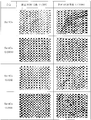
- the initial phase Cu 6 Sn 5 intermetallic compound does not grow and is in the form of particles. This phenomenon is somewhat different depending on the amount of Al added, but all three samples were confirmed to be particulate.
- the mechanism by which the growth of the primary phase Cu 6 Sn 5 intermetallic compound when Al is added has not been deduced so far, each of the dispersed Al fine particles has a primary phase Cu 6 Sn. Since it becomes a nucleus of a pentametallic compound, the nucleation frequency is increased, which is considered to be caused by a slow growth rate.
- the addition of Al is not a factor in reducing the total amount of Cu 6 Sn 5 intermetallic compound originally has become a factor of the Cu 6 Sn 5 intermetallic compound exhibiting a dendritic structure does not grow into dendritic.
- the addition amount of Al in each sample shown in FIG. 1 is an actual measurement value. Al is smaller in density than Sn, and there are some that diffuse uniformly and those that float on the surface of the molten metal. In the present invention, in order to precisely specify the amount of Al that works effectively, the amount of Al in the solidified body was measured for the amount of Al added.
- the initial phase Cu 6 Sn 5 intermetallic compound can run over the entire length of the solder joint in the state where Al of FIG. 1 is not added. High nature. That is, in such a state, not only partial cracks are generated, but also the entire solder joint is cracked and the substrates bonded by BGA are peeled off.
- the uniform Sn—Cu phase is continuous in the three types of samples to which Al is added, it is possible to avoid the occurrence of cracks caused by the Cu 6 Sn 5 intermetallic compound.
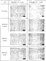
- Fig. 2 compares SEM photographs of a sample with no Al added to Sn-4% Cu-0.05% Ni-0.007% Ge and three samples with Al added as in Fig. 1. Shows what In this sample, Ge is added. However, since Ge itself does not react with Sn and Cu, it is presumed that the same phenomenon can be obtained even in a sample to which Ge is not added. As is apparent from the photographs shown in FIG. 2, the initial phase Cu 6 Sn 5 intermetallic compound is longer in the sample in which Al is added at 60 ppm, 400 ppm, and 1000 ppm, respectively, as compared with the sample to which Al is not added. It was confirmed that the growth stopped at a large number of grains. That is, even in a solder alloy containing Ni as shown in FIG. 2, the addition of Al does not cause the Cu 6 Sn 5 intermetallic compound to grow greatly in the length direction, and the Sn—Cu—Ni phase is continuously formed. Appear.
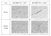
- FIG. 4 a state in which the Cu 6 Sn 5 intermetallic compound is produced when it is contained 7.6 wt% of Cu in Sn as a benchmark, which between Cu 6 Sn 5 metal in the case of adding Al
- the state of compound growth was compared.
- the Cu content in FIG. 4 is not a calculated value but an actually measured value.
- an alloy in which 0.051% by weight Al is added to Sn-7.5Cu an alloy in which 0.143% by weight Al is added to Sn-7.3Cu, and 0.0 to Sn-6.9Cu.
- the Cu 6 Sn 5 intermetallic compound exhibited a large number of grains.
- the Cu content is set to 0.7 to 7.6% by weight, more preferably 2.0 to 7.6% by weight.
- the present invention focuses on the fact that Cu 6 Sn 5 intermetallic compound grows inside the solder joint due to Sn—Cu hypereutectic and cracks occur at the intermetallic compound as a boundary. About the value, it became the lowest limit which becomes a hypereutectic with Sn and the first phase Cu 6 Sn 5 intermetallic compound is generated. In other words, what is important is not the exact value of 0.7% by weight, but the amount exceeding the amount of Cu that causes Sn—Cu hypereutectic in the alloy, that is, the hypereutectic region.
- the more preferable lower limit of Cu is that when 2.0% by weight or more of Cu is contained, the formation of Cu 6 Sn 5 intermetallic compound is remarkable, and the object of the present invention is to appropriately suppress this by adding Al. Because it contributes to.
- the upper limit if it exceeds 7.6% by weight, Cu 3 Sn having a melting point of 415 ° C. is formed in the intermetallic compound, so that this is considered to be avoided.
- the lower limit of the Al or Al 2 O 3 results of the experiment, due to the fact that it was found that the length direction of the growth of the primary phase Cu 6 Sn 5 intermetallic compound is suppressed when it exceeds 0.006 wt%.
- the upper limit if it exceeds 0.15% by weight, in the case of Al, a large amount of oxide film is formed at the time of addition, and the surface becomes black, so a step to avoid this is necessary, and the production efficiency is reduced. In addition, since a large amount of dross containing Al and Al is generated and floats on the surface of the molten solder, it is considered that the production efficiency is similarly reduced.
- Al in the present invention is not intended to react with other elements, but suppresses the growth of the primary phase Cu 6 Sn 5 intermetallic compound, and the primary phase Cu 6 Sn 5 metal is granular with Al as the core.
- the main purpose is to grow intermetallic compounds, and Al 2 O 3 , which is an oxide of Al, can be used as a core composition.
- the addition of Al suppresses the growth of the dendritic structure of the primary phase Cu 6 Sn 5 intermetallic compound, so that only binary alloys having Sn—Cu as the main metal can be used.
- an alloy is obtained by adding a further metal to Sn—Cu, such as a ternary alloy to which Ni is added or a ternary alloy to which Ag is added, the object of the present invention is not impaired. .
- the present invention by adding a small amount of Al to an alloy containing Sn—Cu as a main element and an alloy containing Ni or Ag added thereto, the length direction of the primary phase Cu 6 Sn 5 intermetallic compound Growth is suppressed, and a Cu 6 Sn 5 intermetallic compound is produced in a granular form with Al as a nucleus. Accordingly, since the Sn—Cu phase and the like appear in a continuous state in the solidified alloy, cracks due to impact are reduced, and a solder alloy having excellent tensile properties can be obtained.
- An SEM cross-sectional photograph when a small amount of Al is added to the Sn—Cu composition is shown.
- the SEM cross-sectional photograph at the time of adding a trace amount of Al to the Sn—Cu—Ni composition is shown.
- the SEM cross-sectional photograph at the time of adding trace amount Al to Sn-2.0Cu composition is shown.
- the SEM cross-sectional photograph when a small amount of Al is added to the Sn-6.9 to 7.6Cu composition is shown.
- a tensile test was performed on the composition of the present invention and a test specimen to which Al was not added.
- the purpose of the test is as shown in FIG. 1 or FIG. 2.
- the initial phase Cu 6 Sn 5 intermetallic compound grows long, so that the structure becomes non-uniform and the tensile test is performed.
- the reason is to confirm the inference that the structure to which the Al is added will be stronger than the structure to which Al does not be added because it breaks with a relatively small force while the structure to which Al is added exhibits a uniform state.
- the test piece was precisely weighed in a graphite crucible made by Nippon Crucible Co., Ltd.
- the total weight of the alloy was 600 g for each sample, and heated to 450 ° C. in an electric furnace made by Shinyo Rika in the atmosphere. The sample was dissolved uniformly. Thereafter, the sample was poured into a stainless steel mold left at room temperature, allowed to cool at room temperature for 15 minutes, and then a sample was taken out to obtain a test specimen for measurement.
- the weight of the test piece was about 170 g, the dimensions were 170 mm in length, 10 mm in width, and 10 mm in thickness.
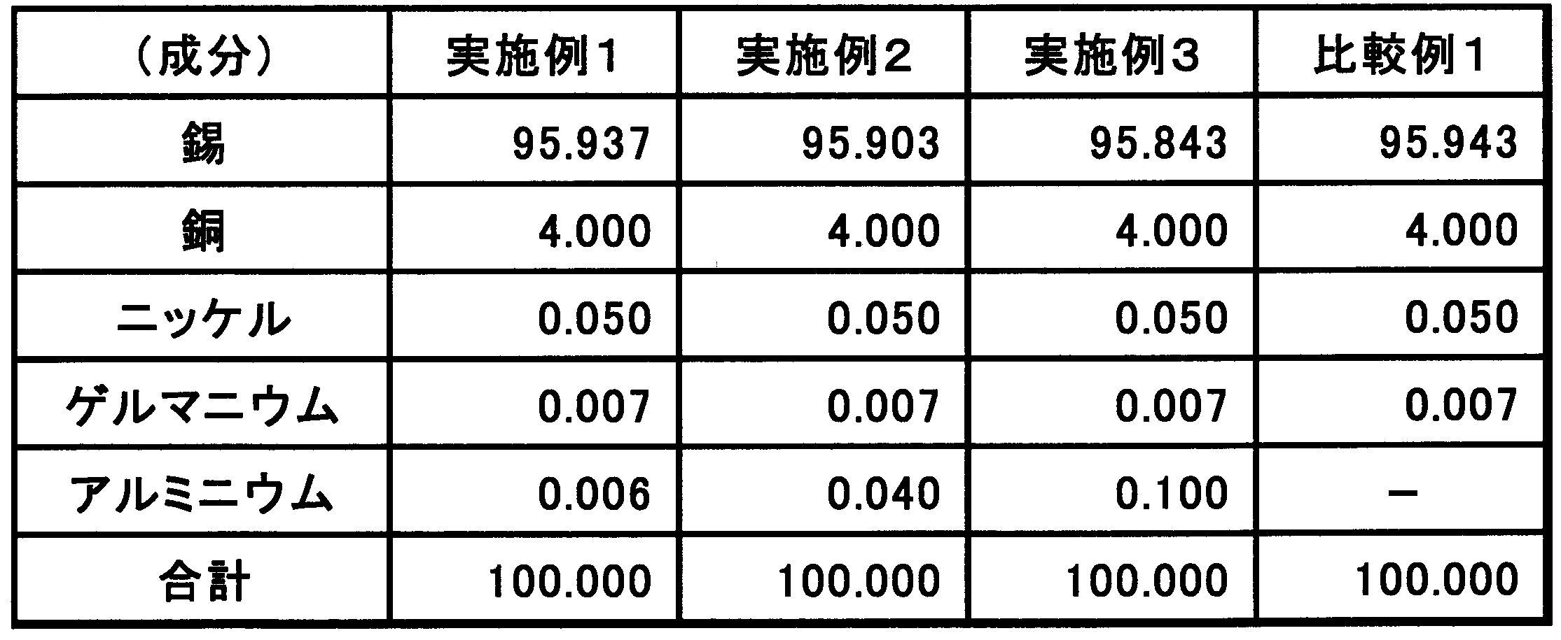
- the test was conducted on four types: a comparative example in which Al was not added and Examples 1 to 3 in which Al was added. Table 1 shows the composition of each sample.
- a test piece was attached to a universal testing machine AG-10kIS manufactured by Shimadzu Corporation, and measurement was performed under the condition of a tensile speed of 10 mm / min.
- FIG. 5 is a graph showing the results of the tensile test, with the left side showing the composition with no added Al and the right three showing the result with the added Al. It is clear from this result that all the samples to which Al was added were excellent in tensile resistance as compared with the samples to which Al was not added. In other words, all the samples to which Al is added are superior in fracture resistance compared to the samples to which Al is not added.
- the growth in the longitudinal direction of the primary phase Cu 6 Sn 5 is suppressed in the hypereutectic composition. Will be reduced.
Abstract
Description
Claims (5)
- Sn-Cu過共晶域で、Cuの含有量が7.6重量%以下に対して、Al又は/及びAl2O30.006~0.15重量%を含むはんだ合金。
- Cu0.7~7.6重量%、Al又は/及びAl2O30.006~0.15重量%、及び残部Snからなるはんだ合金。
- Cuの含有量は、より好ましくは2.0重量%以上である請求項1又は2記載のはんだ合金。
- 請求項1~3のいずれかにおいて、0.03~0.1重量%のSnをNiに置換したはんだ合金。
- 請求項1~4のいずれかにおいて、0.1~3.5重量%のSnをAgに置換したはんだ合金。
Priority Applications (4)
| Application Number | Priority Date | Filing Date | Title |
|---|---|---|---|
| JP2013508941A JP5973992B2 (ja) | 2011-04-08 | 2012-04-06 | はんだ合金 |
| US14/110,458 US9999945B2 (en) | 2011-04-08 | 2012-04-06 | Solder alloy |
| CN201280017273.6A CN103547407A (zh) | 2011-04-08 | 2012-04-06 | 焊锡合金 |
| EP12768679.8A EP2695701A4 (en) | 2011-04-08 | 2012-04-06 | solder alloy |
Applications Claiming Priority (2)
| Application Number | Priority Date | Filing Date | Title |
|---|---|---|---|
| JP2011086183 | 2011-04-08 | ||
| JP2011-086183 | 2011-04-08 |
Publications (1)
| Publication Number | Publication Date |
|---|---|
| WO2012137901A1 true WO2012137901A1 (ja) | 2012-10-11 |
Family
ID=46969289
Family Applications (1)
| Application Number | Title | Priority Date | Filing Date |
|---|---|---|---|
| PCT/JP2012/059465 WO2012137901A1 (ja) | 2011-04-08 | 2012-04-06 | はんだ合金 |
Country Status (5)
| Country | Link |
|---|---|
| US (1) | US9999945B2 (ja) |
| EP (1) | EP2695701A4 (ja) |
| JP (1) | JP5973992B2 (ja) |
| CN (1) | CN103547407A (ja) |
| WO (1) | WO2012137901A1 (ja) |
Cited By (2)
| Publication number | Priority date | Publication date | Assignee | Title |
|---|---|---|---|---|
| WO2014084242A1 (ja) * | 2012-11-30 | 2014-06-05 | 株式会社日本スペリア社 | 低融点ろう材 |
| JP2017213602A (ja) * | 2016-05-31 | 2017-12-07 | 株式会社日本スペリア社 | はんだ付け方法及びはんだ継手 |
Families Citing this family (4)
| Publication number | Priority date | Publication date | Assignee | Title |
|---|---|---|---|---|
| CN104245203B (zh) * | 2012-03-05 | 2016-10-12 | 株式会社村田制作所 | 接合方法、电子装置的制造方法和电子部件 |
| US10329642B2 (en) * | 2013-03-13 | 2019-06-25 | Nihon Superior Co., Ltd. | Solder alloy and joint thereof |
| JP6369620B1 (ja) * | 2017-12-31 | 2018-08-08 | 千住金属工業株式会社 | はんだ合金 |
| CN109014652A (zh) * | 2018-09-26 | 2018-12-18 | 深圳市安臣焊锡制品有限公司 | 一种环保型焊锡材料及其制备工艺 |
Citations (8)
| Publication number | Priority date | Publication date | Assignee | Title |
|---|---|---|---|---|
| WO1999048639A1 (fr) | 1998-03-26 | 1999-09-30 | Nihon Superior Sha Co., Ltd. | Soudure sans plomb |
| JP2003211283A (ja) * | 2002-01-22 | 2003-07-29 | Japan Science & Technology Corp | 鉛フリーはんだ材料 |
| JP2005125360A (ja) * | 2003-10-23 | 2005-05-19 | Matsushita Electric Ind Co Ltd | 高温はんだ材料,高温はんだ材料評価方法および電気/電子機器ならびにはんだ接合構造体 |
| JP2005238328A (ja) | 2004-01-30 | 2005-09-08 | Japan Science & Technology Agency | 鉛フリーはんだ合金、鉛フリーはんだ合金の製造方法、実装構造体、実装方法、鉛フリーヒューズ合金、鉛フリーヒューズ合金の製造方法、板状ヒューズ、鉛フリー合金および鉛フリー合金の製造方法 |
| JP2005296983A (ja) * | 2004-04-09 | 2005-10-27 | Hitachi Metals Ltd | はんだ合金およびはんだボール |
| JP2005319470A (ja) | 2004-05-06 | 2005-11-17 | Katsuaki Suganuma | 鉛フリーはんだ材料、電子回路基板およびそれらの製造方法 |
| JP2007190603A (ja) * | 2006-01-23 | 2007-08-02 | Nippon Alum Co Ltd | はんだ接合方法及びはんだ接合体 |
| JP2008030047A (ja) * | 2006-07-26 | 2008-02-14 | Eishin Kogyo Kk | 無鉛ハンダ |
Family Cites Families (12)
| Publication number | Priority date | Publication date | Assignee | Title |
|---|---|---|---|---|
| JP2000197988A (ja) * | 1998-03-26 | 2000-07-18 | Nihon Superior Co Ltd | 無鉛はんだ合金 |
| KR100374173B1 (ko) * | 1999-06-29 | 2003-03-03 | 김성진 | 아연의 산화가 방지되는 주석-아연계 무연 땜납 |
| JP2002120086A (ja) * | 2000-10-12 | 2002-04-23 | Sanyo Electric Co Ltd | 無鉛はんだ及びその製造方法 |
| JP2006289434A (ja) * | 2005-04-11 | 2006-10-26 | Nihon Superior Co Ltd | はんだ合金 |
| CN1313631C (zh) * | 2005-08-02 | 2007-05-02 | 马莒生 | 一种锡银铜镍铝系无铅焊料合金 |
| US8641964B2 (en) * | 2005-08-24 | 2014-02-04 | Fry's Metals, Inc. | Solder alloy |
| US20080159904A1 (en) * | 2005-08-24 | 2008-07-03 | Fry's Metals, Inc. | Solder alloy |
| EP1924394A2 (en) * | 2005-08-24 | 2008-05-28 | FRY'S METALS, INC. d/b/a ALPHA METALS, INC. | Solder alloy |
| CN100396426C (zh) * | 2005-12-12 | 2008-06-25 | 黄德欢 | 一种Al-Cu-Sn系无铅焊锡 |
| EP2647467A3 (en) * | 2006-07-05 | 2014-04-02 | Fuji Electric Holdings Co., Ltd. | Solder cream and method of soldering electronic parts |
| CN1974110A (zh) * | 2006-12-12 | 2007-06-06 | 黄德欢 | 一种多元无铅焊锡 |
| WO2009009877A1 (en) * | 2007-07-13 | 2009-01-22 | Nichol Scott E | Metal matrix composite solders |
-
2012
- 2012-04-06 JP JP2013508941A patent/JP5973992B2/ja not_active Expired - Fee Related
- 2012-04-06 WO PCT/JP2012/059465 patent/WO2012137901A1/ja active Application Filing
- 2012-04-06 EP EP12768679.8A patent/EP2695701A4/en not_active Withdrawn
- 2012-04-06 CN CN201280017273.6A patent/CN103547407A/zh active Pending
- 2012-04-06 US US14/110,458 patent/US9999945B2/en not_active Expired - Fee Related
Patent Citations (8)
| Publication number | Priority date | Publication date | Assignee | Title |
|---|---|---|---|---|
| WO1999048639A1 (fr) | 1998-03-26 | 1999-09-30 | Nihon Superior Sha Co., Ltd. | Soudure sans plomb |
| JP2003211283A (ja) * | 2002-01-22 | 2003-07-29 | Japan Science & Technology Corp | 鉛フリーはんだ材料 |
| JP2005125360A (ja) * | 2003-10-23 | 2005-05-19 | Matsushita Electric Ind Co Ltd | 高温はんだ材料,高温はんだ材料評価方法および電気/電子機器ならびにはんだ接合構造体 |
| JP2005238328A (ja) | 2004-01-30 | 2005-09-08 | Japan Science & Technology Agency | 鉛フリーはんだ合金、鉛フリーはんだ合金の製造方法、実装構造体、実装方法、鉛フリーヒューズ合金、鉛フリーヒューズ合金の製造方法、板状ヒューズ、鉛フリー合金および鉛フリー合金の製造方法 |
| JP2005296983A (ja) * | 2004-04-09 | 2005-10-27 | Hitachi Metals Ltd | はんだ合金およびはんだボール |
| JP2005319470A (ja) | 2004-05-06 | 2005-11-17 | Katsuaki Suganuma | 鉛フリーはんだ材料、電子回路基板およびそれらの製造方法 |
| JP2007190603A (ja) * | 2006-01-23 | 2007-08-02 | Nippon Alum Co Ltd | はんだ接合方法及びはんだ接合体 |
| JP2008030047A (ja) * | 2006-07-26 | 2008-02-14 | Eishin Kogyo Kk | 無鉛ハンダ |
Non-Patent Citations (1)
| Title |
|---|
| See also references of EP2695701A4 * |
Cited By (3)
| Publication number | Priority date | Publication date | Assignee | Title |
|---|---|---|---|---|
| WO2014084242A1 (ja) * | 2012-11-30 | 2014-06-05 | 株式会社日本スペリア社 | 低融点ろう材 |
| JPWO2014084242A1 (ja) * | 2012-11-30 | 2017-01-05 | 株式会社日本スペリア社 | 低融点ろう材 |
| JP2017213602A (ja) * | 2016-05-31 | 2017-12-07 | 株式会社日本スペリア社 | はんだ付け方法及びはんだ継手 |
Also Published As
| Publication number | Publication date |
|---|---|
| EP2695701A1 (en) | 2014-02-12 |
| US20140030140A1 (en) | 2014-01-30 |
| JP5973992B2 (ja) | 2016-08-23 |
| JPWO2012137901A1 (ja) | 2014-07-28 |
| US9999945B2 (en) | 2018-06-19 |
| EP2695701A4 (en) | 2014-09-24 |
| CN103547407A (zh) | 2014-01-29 |
Similar Documents
| Publication | Publication Date | Title |
|---|---|---|
| KR101561894B1 (ko) | 고온 납 프리 땜납 합금 | |
| CN110612175B (zh) | 软钎料合金 | |
| JP5973992B2 (ja) | はんだ合金 | |
| KR101671062B1 (ko) | 무연 솔더 합금 조성물 및 무연 솔더 합금의 제조 방법 | |
| JP5715399B2 (ja) | 電気・電子部品用銅合金材 | |
| WO2007102588A1 (ja) | 鉛フリーハンダ合金、ハンダボール及び電子部材と、自動車搭載電子部材用鉛フリーハンダ合金、ハンダボール及び電子部材 | |
| JPWO2009051255A1 (ja) | はんだ継手 | |
| JP2006255784A (ja) | 無鉛ハンダ合金 | |
| JP6804126B1 (ja) | 鉛フリーはんだ合金及びはんだ接合部 | |
| JP5019764B2 (ja) | 鉛フリーハンダ合金、ハンダボール及び電子部材 | |
| JP2007237249A (ja) | 鉛フリーハンダ合金、ハンダボール及び電子部材 | |
| JP5379402B2 (ja) | 鉛フリーSn−Ag系半田合金及び半田合金粉末 | |
| TW202138576A (zh) | 無鉛且無銻之焊料合金、焊球,及焊料接頭 | |
| JP2007237251A (ja) | 鉛フリーハンダ合金、ハンダボール及び電子部材 | |
| JP2009082986A (ja) | マニュアルソルダリング用無鉛はんだ合金 | |
| CN111542624A (zh) | 用于高可靠性应用的标准sac合金的低银锡基替代焊料合金 | |
| JP5240938B2 (ja) | Sn−Sb系半田合金 | |
| JP4425738B2 (ja) | 鉛フリーはんだ合金、鉛フリーはんだ合金の製造方法、実装構造体、実装方法、鉛フリーヒューズ合金、鉛フリーヒューズ合金の製造方法、板状ヒューズ、鉛フリー合金および鉛フリー合金の製造方法 | |
| JP2008188672A (ja) | マニュアルソルダリング用無鉛はんだ合金 | |
| JP2016093831A (ja) | Pbを含まないMg−Cu系はんだ合金 | |
| JP5861526B2 (ja) | Pbを含まないGe−Al系はんだ合金 | |
| JP7273049B2 (ja) | 電子用途のコスト効率の良い鉛フリーはんだ合金 | |
| JP2015020189A (ja) | Auを主成分とするPbフリーAu−Ge−Sn系はんだ合金 | |
| JP5903626B2 (ja) | 鉛フリーはんだ合金 | |
| JP2017047439A (ja) | PbフリーSn系はんだ合金及びこれを用いた電子部品実装基板並びに該実装基板を搭載した電子機器 |
Legal Events
| Date | Code | Title | Description |
|---|---|---|---|
| 121 | Ep: the epo has been informed by wipo that ep was designated in this application |
Ref document number: 12768679 Country of ref document: EP Kind code of ref document: A1 |
|
| WWE | Wipo information: entry into national phase |
Ref document number: 2012768679 Country of ref document: EP |
|
| ENP | Entry into the national phase |
Ref document number: 2013508941 Country of ref document: JP Kind code of ref document: A |
|
| NENP | Non-entry into the national phase |
Ref country code: DE |
|
| WWE | Wipo information: entry into national phase |
Ref document number: 14110458 Country of ref document: US |