WO2012132059A1 - 二次電池および電解液 - Google Patents
二次電池および電解液 Download PDFInfo
- Publication number
- WO2012132059A1 WO2012132059A1 PCT/JP2011/072034 JP2011072034W WO2012132059A1 WO 2012132059 A1 WO2012132059 A1 WO 2012132059A1 JP 2011072034 W JP2011072034 W JP 2011072034W WO 2012132059 A1 WO2012132059 A1 WO 2012132059A1
- Authority
- WO
- WIPO (PCT)
- Prior art keywords
- secondary battery
- chain fluorinated
- alkyl group
- battery according
- fluorine
- Prior art date
Links
Images
Classifications
-
- H—ELECTRICITY
- H01—ELECTRIC ELEMENTS
- H01M—PROCESSES OR MEANS, e.g. BATTERIES, FOR THE DIRECT CONVERSION OF CHEMICAL ENERGY INTO ELECTRICAL ENERGY
- H01M10/00—Secondary cells; Manufacture thereof
- H01M10/05—Accumulators with non-aqueous electrolyte
- H01M10/056—Accumulators with non-aqueous electrolyte characterised by the materials used as electrolytes, e.g. mixed inorganic/organic electrolytes
- H01M10/0564—Accumulators with non-aqueous electrolyte characterised by the materials used as electrolytes, e.g. mixed inorganic/organic electrolytes the electrolyte being constituted of organic materials only
- H01M10/0566—Liquid materials
-
- H—ELECTRICITY
- H01—ELECTRIC ELEMENTS
- H01M—PROCESSES OR MEANS, e.g. BATTERIES, FOR THE DIRECT CONVERSION OF CHEMICAL ENERGY INTO ELECTRICAL ENERGY
- H01M4/00—Electrodes
- H01M4/02—Electrodes composed of, or comprising, active material
- H01M4/36—Selection of substances as active materials, active masses, active liquids
- H01M4/362—Composites
- H01M4/364—Composites as mixtures
-
- H—ELECTRICITY
- H01—ELECTRIC ELEMENTS
- H01M—PROCESSES OR MEANS, e.g. BATTERIES, FOR THE DIRECT CONVERSION OF CHEMICAL ENERGY INTO ELECTRICAL ENERGY
- H01M10/00—Secondary cells; Manufacture thereof
- H01M10/05—Accumulators with non-aqueous electrolyte
- H01M10/052—Li-accumulators
-
- H—ELECTRICITY
- H01—ELECTRIC ELEMENTS
- H01M—PROCESSES OR MEANS, e.g. BATTERIES, FOR THE DIRECT CONVERSION OF CHEMICAL ENERGY INTO ELECTRICAL ENERGY
- H01M10/00—Secondary cells; Manufacture thereof
- H01M10/05—Accumulators with non-aqueous electrolyte
- H01M10/056—Accumulators with non-aqueous electrolyte characterised by the materials used as electrolytes, e.g. mixed inorganic/organic electrolytes
- H01M10/0564—Accumulators with non-aqueous electrolyte characterised by the materials used as electrolytes, e.g. mixed inorganic/organic electrolytes the electrolyte being constituted of organic materials only
- H01M10/0566—Liquid materials
- H01M10/0567—Liquid materials characterised by the additives
-
- H—ELECTRICITY
- H01—ELECTRIC ELEMENTS
- H01M—PROCESSES OR MEANS, e.g. BATTERIES, FOR THE DIRECT CONVERSION OF CHEMICAL ENERGY INTO ELECTRICAL ENERGY
- H01M10/00—Secondary cells; Manufacture thereof
- H01M10/05—Accumulators with non-aqueous electrolyte
- H01M10/056—Accumulators with non-aqueous electrolyte characterised by the materials used as electrolytes, e.g. mixed inorganic/organic electrolytes
- H01M10/0564—Accumulators with non-aqueous electrolyte characterised by the materials used as electrolytes, e.g. mixed inorganic/organic electrolytes the electrolyte being constituted of organic materials only
- H01M10/0566—Liquid materials
- H01M10/0569—Liquid materials characterised by the solvents
-
- H—ELECTRICITY
- H01—ELECTRIC ELEMENTS
- H01M—PROCESSES OR MEANS, e.g. BATTERIES, FOR THE DIRECT CONVERSION OF CHEMICAL ENERGY INTO ELECTRICAL ENERGY
- H01M4/00—Electrodes
- H01M4/02—Electrodes composed of, or comprising, active material
- H01M4/36—Selection of substances as active materials, active masses, active liquids
- H01M4/38—Selection of substances as active materials, active masses, active liquids of elements or alloys
- H01M4/386—Silicon or alloys based on silicon
-
- H—ELECTRICITY
- H01—ELECTRIC ELEMENTS
- H01M—PROCESSES OR MEANS, e.g. BATTERIES, FOR THE DIRECT CONVERSION OF CHEMICAL ENERGY INTO ELECTRICAL ENERGY
- H01M4/00—Electrodes
- H01M4/02—Electrodes composed of, or comprising, active material
- H01M4/36—Selection of substances as active materials, active masses, active liquids
- H01M4/48—Selection of substances as active materials, active masses, active liquids of inorganic oxides or hydroxides
- H01M4/485—Selection of substances as active materials, active masses, active liquids of inorganic oxides or hydroxides of mixed oxides or hydroxides for inserting or intercalating light metals, e.g. LiTi2O4 or LiTi2OxFy
-
- H—ELECTRICITY
- H01—ELECTRIC ELEMENTS
- H01M—PROCESSES OR MEANS, e.g. BATTERIES, FOR THE DIRECT CONVERSION OF CHEMICAL ENERGY INTO ELECTRICAL ENERGY
- H01M4/00—Electrodes
- H01M4/02—Electrodes composed of, or comprising, active material
- H01M4/36—Selection of substances as active materials, active masses, active liquids
- H01M4/58—Selection of substances as active materials, active masses, active liquids of inorganic compounds other than oxides or hydroxides, e.g. sulfides, selenides, tellurides, halogenides or LiCoFy; of polyanionic structures, e.g. phosphates, silicates or borates
- H01M4/583—Carbonaceous material, e.g. graphite-intercalation compounds or CFx
- H01M4/587—Carbonaceous material, e.g. graphite-intercalation compounds or CFx for inserting or intercalating light metals
-
- H—ELECTRICITY
- H01—ELECTRIC ELEMENTS
- H01M—PROCESSES OR MEANS, e.g. BATTERIES, FOR THE DIRECT CONVERSION OF CHEMICAL ENERGY INTO ELECTRICAL ENERGY
- H01M2300/00—Electrolytes
- H01M2300/0017—Non-aqueous electrolytes
- H01M2300/0025—Organic electrolyte
- H01M2300/0028—Organic electrolyte characterised by the solvent
- H01M2300/0034—Fluorinated solvents
-
- H—ELECTRICITY
- H01—ELECTRIC ELEMENTS
- H01M—PROCESSES OR MEANS, e.g. BATTERIES, FOR THE DIRECT CONVERSION OF CHEMICAL ENERGY INTO ELECTRICAL ENERGY
- H01M2300/00—Electrolytes
- H01M2300/0017—Non-aqueous electrolytes
- H01M2300/0025—Organic electrolyte
- H01M2300/0028—Organic electrolyte characterised by the solvent
- H01M2300/0037—Mixture of solvents
- H01M2300/004—Three solvents
-
- H—ELECTRICITY
- H01—ELECTRIC ELEMENTS
- H01M—PROCESSES OR MEANS, e.g. BATTERIES, FOR THE DIRECT CONVERSION OF CHEMICAL ENERGY INTO ELECTRICAL ENERGY
- H01M4/00—Electrodes
- H01M4/02—Electrodes composed of, or comprising, active material
- H01M4/62—Selection of inactive substances as ingredients for active masses, e.g. binders, fillers
- H01M4/621—Binders
- H01M4/622—Binders being polymers
-
- Y—GENERAL TAGGING OF NEW TECHNOLOGICAL DEVELOPMENTS; GENERAL TAGGING OF CROSS-SECTIONAL TECHNOLOGIES SPANNING OVER SEVERAL SECTIONS OF THE IPC; TECHNICAL SUBJECTS COVERED BY FORMER USPC CROSS-REFERENCE ART COLLECTIONS [XRACs] AND DIGESTS
- Y02—TECHNOLOGIES OR APPLICATIONS FOR MITIGATION OR ADAPTATION AGAINST CLIMATE CHANGE
- Y02E—REDUCTION OF GREENHOUSE GAS [GHG] EMISSIONS, RELATED TO ENERGY GENERATION, TRANSMISSION OR DISTRIBUTION
- Y02E60/00—Enabling technologies; Technologies with a potential or indirect contribution to GHG emissions mitigation
- Y02E60/10—Energy storage using batteries
-
- Y—GENERAL TAGGING OF NEW TECHNOLOGICAL DEVELOPMENTS; GENERAL TAGGING OF CROSS-SECTIONAL TECHNOLOGIES SPANNING OVER SEVERAL SECTIONS OF THE IPC; TECHNICAL SUBJECTS COVERED BY FORMER USPC CROSS-REFERENCE ART COLLECTIONS [XRACs] AND DIGESTS
- Y02—TECHNOLOGIES OR APPLICATIONS FOR MITIGATION OR ADAPTATION AGAINST CLIMATE CHANGE
- Y02P—CLIMATE CHANGE MITIGATION TECHNOLOGIES IN THE PRODUCTION OR PROCESSING OF GOODS
- Y02P70/00—Climate change mitigation technologies in the production process for final industrial or consumer products
- Y02P70/50—Manufacturing or production processes characterised by the final manufactured product
-
- Y—GENERAL TAGGING OF NEW TECHNOLOGICAL DEVELOPMENTS; GENERAL TAGGING OF CROSS-SECTIONAL TECHNOLOGIES SPANNING OVER SEVERAL SECTIONS OF THE IPC; TECHNICAL SUBJECTS COVERED BY FORMER USPC CROSS-REFERENCE ART COLLECTIONS [XRACs] AND DIGESTS
- Y02—TECHNOLOGIES OR APPLICATIONS FOR MITIGATION OR ADAPTATION AGAINST CLIMATE CHANGE
- Y02T—CLIMATE CHANGE MITIGATION TECHNOLOGIES RELATED TO TRANSPORTATION
- Y02T10/00—Road transport of goods or passengers
- Y02T10/60—Other road transportation technologies with climate change mitigation effect
- Y02T10/70—Energy storage systems for electromobility, e.g. batteries
Definitions
- Embodiments according to the present invention relate to a secondary battery and an electrolyte for a secondary battery used therein, and more particularly, to a lithium ion secondary battery and an electrolyte for a secondary battery used therefor.
- Examples of means for obtaining a secondary battery having a high energy density include a method using a negative electrode material having a large capacity, a method using an electrolyte solution having excellent stability, and the like.
- Patent Document 1 discloses that silicon oxide or silicate is used as a negative electrode active material of a secondary battery.
- Patent Document 2 discloses a negative electrode for a secondary battery including an active material layer including carbon material particles capable of inserting and extracting lithium ions, metal particles capable of being alloyed with lithium, and oxide particles capable of inserting and extracting lithium ions. Is disclosed.
- Patent Document 3 discloses a negative electrode material for a secondary battery in which the surface of particles having a structure in which silicon microcrystals are dispersed in a silicon compound is coated with carbon. The negative electrode active material described in Patent Documents 2 and 3 has an effect of relaxing the volume change as a whole of the negative electrode.
- an electrolytic solution for example, as disclosed in Patent Documents 4 to 6, an electrolytic solution containing other compounds in addition to a commonly used nonaqueous electrolytic solution has been tried.
- Patent Document 4 discloses using an electrolyte containing an asymmetric acyclic sulfone and a chain ester compound.
- Patent Documents 5 and 6 describe using a nonaqueous electrolytic solution containing a fluorinated ether.
- Patent Document 7 an electrolytic solution containing any one compound of fluorine-containing ether, fluorine-containing ester, and fluorine-containing carbonate is described.
- the secondary battery is required to have a small volume increase when repeatedly charged and discharged.
- an object of the embodiment according to the present invention is to provide a secondary battery that is excellent in cycle characteristics even in a high temperature environment, has a small increase in resistance even when used in a high temperature environment, and suppresses an increase in volume.
- a secondary battery comprising a positive electrode, a negative electrode, and an electrolyte solution
- the electrolytic solution includes a chain fluorinated sulfone compound represented by the following formula (1).
- R 1 and R 2 each independently represent a substituted or unsubstituted alkyl group or a substituted or unsubstituted aryl group, and at least one of R 1 and R 2 represents a fluorine atom. Included.
- One of the embodiments according to the present invention is as follows. It is the electrolyte solution for secondary batteries characterized by including the chain
- the embodiment of the present invention it is possible to provide a secondary battery that is excellent in cycle characteristics even in a high temperature environment and has a small increase in resistance even when used in a high temperature environment.
- FIG. 3 is a schematic cross-sectional view showing a structure of an electrode element included in a laminated laminate type secondary battery.
- the electrolytic solution in the present embodiment includes a chain fluorinated sulfone compound represented by the following formula (1).
- a chain fluorinated sulfone compound represented by the following formula (1).
- SEI coating solid liquid interface coating
- R 1 and R 2 each independently represent a substituted or unsubstituted alkyl group or a substituted or unsubstituted aryl group, and at least one of R 1 and R 2 contains a fluorine atom. .
- the alkyl group preferably has 1 to 12 carbon atoms, more preferably 1 to 8 carbon atoms, still more preferably 1 to 6 carbon atoms. It is particularly preferable that the number is 4.
- the aryl group preferably has 6 to 18 carbon atoms, more preferably 6 to 12 carbon atoms, and still more preferably 6 to 10 carbon atoms.
- At least one of R 1 and R 2 contains a fluorine atom. Accordingly, at least one of R 1 and R 2 preferably has a fluorine atom as a substituent, and at least one of R 1 and R 2 is preferably a fluorine-substituted alkyl group.
- the fluorine-substituted alkyl group represents a substituted alkyl group having a structure in which at least one hydrogen atom of the unsubstituted alkyl group is substituted with a fluorine atom.
- the alkyl group includes a linear, branched or cyclic group, but the fluorine-substituted alkyl group is preferably linear.
- R 1 and R 2 other substituents include, for example, an alkyl group having 1 to 6 carbon atoms (for example, methyl group, ethyl group, propyl group, isopropyl group, butyl group), aryl having 6 to 10 carbon atoms Group (for example, phenyl group, naphthyl group), halogen atom (for example, chlorine atom, bromine atom) and the like.
- an alkyl group having 1 to 6 carbon atoms for example, methyl group, ethyl group, propyl group, isopropyl group, butyl group
- aryl having 6 to 10 carbon atoms Group for example, phenyl group, naphthyl group
- halogen atom for example, chlorine atom, bromine atom
- R 1 and R 2 are preferably each independently a fluorine-substituted alkyl group.
- R 1 and R 2 are each independently preferably a fluorine-substituted alkyl group having 1 to 6 carbon atoms, and more preferably a fluorine-substituted alkyl group having 1 to 4 carbon atoms.
- one of R 1 and R 2 is a fluorine-substituted alkyl group having 1 to 6 carbon atoms, and the other is an alkyl group having 1 to 6 carbon atoms that may be substituted with an aryl group, or An aryl group having 6 to 10 carbon atoms which may be substituted with an alkyl group is preferable.
- the chain fluorinated sulfone compound can be used alone or in combination of two or more.
- the content of the chain fluorinated sulfone compound in the electrolytic solution is not particularly limited, but is preferably 0.01 to 30% by mass, and more preferably 0.1 to 20% by mass. More preferably, it is 1 to 10% by mass.
- the content of the chain fluorinated sulfone compound is not particularly limited, but is preferably 0.01 to 30% by mass, and more preferably 0.1 to 20% by mass. More preferably, it is 1 to 10% by mass.
- the electrolytic solution preferably further contains a chain fluorinated ether compound represented by the following formula (2).
- a chain fluorinated ether compound represented by the following formula (2).
- R a and R b each independently represent an alkyl group or a fluorine-substituted alkyl group, and at least one of R a and R b is a fluorine-substituted alkyl group.
- the alkyl group preferably has 1 to 12 carbon atoms, more preferably 1 to 8, more preferably 1 to 6, and more preferably 1 to 4. Particularly preferred. Further, in the formula (2), the alkyl group includes a linear, branched or cyclic group, but is preferably a linear group.
- At least one of R a and R b is a fluorine-substituted alkyl group.
- the fluorine-substituted alkyl group represents a substituted alkyl group having a structure in which at least one hydrogen atom of the unsubstituted alkyl group is substituted with a fluorine atom.
- the fluorine-substituted alkyl group is preferably linear.
- R a and R b are each independently preferably a fluorine-substituted alkyl group having 1 to 6 carbon atoms, and more preferably a fluorine-substituted alkyl group having 1 to 4 carbon atoms.
- the chain fluorinated ether is preferably a compound represented by the following formula (3) from the viewpoint of voltage resistance and compatibility with other electrolytes.
- n is 1 to 8
- Y 1 to Y 8 are each independently a fluorine atom or a hydrogen atom, provided that at least one of Y 1 to Y 3 is a fluorine atom.
- At least one of Y 4 to Y 8 is a fluorine atom).
- Y 2 and Y 3 may be independent for each n.
- the chain fluorinated ether compound is more preferably represented by the following formula (4) from the viewpoint of the viscosity of the electrolytic solution and compatibility with other electrolytes typified by chain fluorinated sulfone. .
- n is 1, 2, 3 or 4.
- X 1 to X 8 are each independently a fluorine atom or a hydrogen atom. However, at least one of X 1 to X 4 is a fluorine atom, and at least one of X 5 to X 8 is a fluorine atom.
- X 1 to X 4 may be independent for each n.
- n is preferably 1 or 2, and n is more preferably 1.
- the atomic ratio of fluorine atoms to hydrogen atoms is preferably 1 or more.
- chain fluorinated ether compound examples include CF 3 OCH 3 , CF 3 OC 2 H 6 , F (CF 2 ) 2 OCH 3 , F (CF 2 ) 2 OC 2 H 5 , and F (CF 2 ) 3 OCH.
- the content of the chain fluorinated ether compound in the electrolytic solution is, for example, 1 to 70% by mass.
- the content of the chain fluorinated ether compound in the electrolytic solution is preferably 5 to 60% by mass, more preferably 7 to 50% by mass, and further preferably 10 to 40% by mass. preferable.
- the content of the chain fluorinated ether compound is 60% by mass or less, Li ions dissociate easily in the supporting salt, and the conductivity of the electrolytic solution is improved.
- strand-shaped fluorinated ether compound is 5 mass% or more, it is thought that it becomes easy to suppress reductive decomposition on the negative electrode of electrolyte solution.
- Solvents that can be used for the electrolyte include cyclic carbonates such as propylene carbonate (PC), ethylene carbonate (EC), butylene carbonate (BC), and vinylene carbonate (VC); dimethyl carbonate (DMC), diethyl carbonate ( Aprotic such as chain carbonates such as DEC), ethyl methyl carbonate (EMC), dipropyl carbonate (DPC); propylene carbonate derivatives; aliphatic carboxylic acid esters such as methyl formate, methyl acetate, ethyl propionate; A solvent is mentioned. These aprotic solvents can be used individually by 1 type or in combination of 2 or more types.
- PC propylene carbonate
- EC ethylene carbonate
- BC butylene carbonate
- VVC vinylene carbonate
- DMC dimethyl carbonate
- Aprotic such as chain carbonates such as DEC
- EMC ethyl methyl carbonate
- DPC dipropyl carbonate
- the electrolytic solution preferably contains a carbonate compound (non-fluorinated) as a solvent.
- a carbonate compound By using a carbonate compound, the ion dissociation property of the electrolytic solution is improved, and the viscosity of the electrolytic solution is lowered. Therefore, ion mobility can be improved.
- the carbonate compound include cyclic carbonates and chain carbonates as described above.
- the carbonate compound include ethylene carbonate (EC), propylene carbonate (PC), butylene carbonate (BC), vinylene carbonate (VC), dimethyl carbonate (DMC), diethyl carbonate (DEC), and ethyl methyl as described above. Examples include carbonate (MEC) and dipropyl carbonate (DPC).
- the electrolytic solution preferably contains a carbonate compound as a main solvent.
- the content of the carbonate compound in the solvent is preferably 60% by volume or more, more preferably 70% by volume or more, further preferably 80% by volume or more, and 90% by volume or more. Particularly preferred.
- ⁇ -lactones such as ⁇ -butyrolactone
- chain ethers such as 1,2-ethoxyethane (DEE), ethoxymethoxyethane (EME), tetrahydrofuran, 2-methyltetrahydrofuran
- Cyclic ethers such as dimethyl sulfoxide, 1,3-dioxolane, formamide, acetamide, dimethylformamide, dioxolane, acetonitrile, propylnitrile, nitromethane, ethyl monoglyme, phosphoric acid triester, trimethoxymethane, dioxolane derivatives, sulfolane, methyl Sulfolane, 1,3-dimethyl-2-imidazolidinone, 3-methyl-2-oxazolidinone, propylene carbonate derivative, tetrahydrofuran derivative, ethyl ether, 1,3-propane sultone
- the electrolytic solution in the present embodiment includes a chain fluorinated sulfone compound, a chain fluorinated ether compound, and a carbonate compound. Since the carbonate compound has a large relative dielectric constant, the ion dissociation property of the electrolytic solution is improved. Further, since the viscosity of the electrolytic solution is lowered, the ion mobility is improved. However, when a carbonate compound having a carbonate structure is used as the electrolytic solution, the carbonate compound tends to decompose and a gas composed of CO 2 tends to be generated.
- the content of the chain fluorinated sulfone compound is 1 to 15% by volume based on the total amount of the chain fluorinated sulfone compound, the chain fluorinated ether compound and the solvent, The amount is 10 to 35% by volume based on the total amount of the chain fluorinated sulfone compound, the chain fluorinated ether compound and the solvent, and the content of the carbonate compound is the chain fluorinated sulfone compound and the chain fluorinated ether compound. 30 to 89% by volume based on the total amount of the solvent and the solvent. Further, the content of the chain fluorinated sulfone compound is more preferably 2 to 12% by volume.
- the content of the chain fluorinated ether compound is more preferably 15 to 30% by volume with respect to the total amount of the chain fluorinated sulfone compound, the chain fluorinated ether compound and the solvent.
- the content of the carbonate compound is more preferably 50 to 80% by volume, and 55 to 75% by volume based on the total amount of the chain fluorinated sulfone compound, the chain fluorinated ether compound and the solvent. Further preferred.
- the electrolytic solution can further contain a supporting salt.
- the supporting salt include LiPF 6 , LiAsF 6 , LiAlCl 4 , LiClO 4 , LiBF 4 , LiSbF 6 , LiCF 3 SO 3 , LiC 4 F 9 SO 3 , Li (CF 3 SO 2 ) 2 , LiN (CF 3 And a lithium salt such as SO 2 ) 2 .
- a supporting salt can be used individually by 1 type or in combination of 2 or more types.
- the concentration of the supporting salt in the electrolytic solution is preferably 0.5 to 1.5 mol / l. By setting the concentration of the supporting salt within this range, it is easy to adjust the density, viscosity, electrical conductivity, and the like to an appropriate range.
- the lithium secondary battery of the present embodiment includes a negative electrode having a negative electrode active material.
- the negative electrode active material can be bound on the negative electrode current collector by a negative electrode binder.
- the negative electrode active material in the present embodiment is not particularly limited, and for example, a metal (a) that can be alloyed with lithium, a metal oxide (b) that can occlude and release lithium ions, or occlude lithium ions. And carbon material (c) that can be released.
- Examples of the metal (a) include Al, Si, Pb, Sn, In, Bi, Ag, Ba, Ca, Hg, Pd, Pt, Te, Zn, La, or alloys of two or more thereof. It is done. Moreover, you may use these metals or alloys in mixture of 2 or more types. These metals or alloys may contain one or more non-metallic elements. In this embodiment, it is preferable to use silicon as the negative electrode active material. Silicon is an element with the second largest number of Clarkes following oxygen, and is rich in resources. Moreover, it shows a higher charge capacity than other metals of about 4200 mAh / g.
- the negative electrode active material it is possible to provide a lithium ion battery that is excellent in weight energy density and volume energy density and has few resource restrictions.
- tin can be used as the negative electrode active material, and tin and silicon are preferably used, and an alloy of tin and silicon is more preferably used.
- the content of the metal (a) in the negative electrode active material may be 0% by mass or 100% by mass, but is preferably 5% by mass to 95% by mass, and is preferably 10% by mass to 90% by mass. More preferably, it is more preferably 20% by mass or more and 50% by mass or less.
- the negative electrode containing silicon has a problem that the volume increase due to repeated charge and discharge is large, but by using an electrolytic solution containing a chain fluorinated sulfone compound and a chain fluorinated ether compound, the volume increase due to charge and discharge can be reduced. It turned out that it can suppress.
- the mechanism of the present embodiment is that, as described above, the chain fluorinated ether compound is coordinated or adsorbed on the film formed by the chain fluorinated sulfone compound, thereby suppressing the decomposition of the electrolyte further. As estimated, such a phenomenon is considered to be particularly remarkable in the negative electrode containing silicon. Therefore, in this embodiment, a particularly advantageous effect can be obtained by using a negative electrode containing silicon.
- the metal oxide (b) examples include silicon oxide, aluminum oxide, tin oxide, indium oxide, zinc oxide, lithium oxide, and composites thereof.
- silicon oxide it is preferable to use silicon oxide as the negative electrode active material. This is because silicon oxide is relatively stable and hardly causes a reaction with other compounds.
- one or more elements selected from nitrogen, boron and sulfur may be added to the metal oxide (b), for example, 0.1 to 5% by mass. By carrying out like this, the electrical conductivity of a metal oxide (b) can be improved.
- the content of the metal oxide (b) in the negative electrode active material may be 0% by mass or 100% by mass, but is preferably 5% by mass or more and 90% by mass or less, and 40% by mass or more and 80% by mass or less. It is more preferable to set it as 50 mass% or more and 70 mass% or less.
- Examples of the carbon material (c) include carbon, amorphous carbon, diamond-like carbon, carbon nanotube, or a composite thereof.
- carbon with high crystallinity has high electrical conductivity, and is excellent in adhesiveness and voltage flatness with a negative electrode current collector made of a metal such as copper.
- amorphous carbon having low crystallinity has a relatively small volume expansion, it has a high effect of relaxing the volume expansion of the entire negative electrode, and deterioration due to non-uniformity such as crystal grain boundaries and defects hardly occurs.
- the content of the carbon material (c) in the negative electrode active material may be 0% by mass or 100% by mass, but is preferably 2% by mass or more and 50% by mass or less, and 2% by mass or more and 30% by mass or less. More preferably.
- the negative electrode active material in this embodiment includes a metal (a) that can be alloyed with lithium, a metal oxide (b) that can occlude and release lithium ions, and a carbon material (c) that can occlude and release lithium ions. It is preferable to contain.
- the metal (a) is preferably silicon and the metal oxide (b) is preferably silicon oxide. That is, the negative electrode active material is preferably composed of a composite of silicon, silicon oxide, and a carbon material (hereinafter also referred to as Si / SiO / C composite). Furthermore, it is preferable that the metal oxide (b) has an amorphous structure in whole or in part.
- the metal oxide (b) having an amorphous structure can suppress volume expansion of the carbon material (c) and the metal (a) which are other negative electrode active materials. Although this mechanism is not clear, it is presumed that the metal oxide (b) has some influence on the formation of a film on the interface between the carbon material (c) and the electrolytic solution due to the amorphous structure.
- the amorphous structure is considered to have relatively few elements due to non-uniformity such as crystal grain boundaries and defects. It can be confirmed by X-ray diffraction measurement (general XRD measurement) that all or part of the metal oxide (b) has an amorphous structure.
- the metal oxide (b) does not have an amorphous structure, a peak specific to the metal oxide (b) is observed, but all or part of the metal oxide (b) is amorphous. In the case of having a structure, the intrinsic peak is observed broad in the metal oxide (b).
- the Si / SiO / C composite it is preferable that all or part of silicon is dispersed in silicon oxide.
- silicon oxide By dispersing at least a part of silicon in silicon oxide, volume expansion as a whole of the negative electrode can be further suppressed, and decomposition of the electrolytic solution can also be suppressed.
- all or part of silicon is dispersed in silicon oxide because transmission electron microscope observation (general TEM observation) and energy dispersive X-ray spectroscopy measurement (general EDX measurement) are used in combination. This can be confirmed. Specifically, the cross section of a sample containing silicon particles can be observed, and the oxygen concentration of silicon particles dispersed in silicon oxide can be measured to confirm that it is not an oxide.
- the negative electrode active material containing silicon is particularly preferably a Si / SiO / C composite.
- the negative electrode active material composed of a Si / SiO / C composite and an electrolytic solution containing a chain fluorinated sulfone compound and a chain fluorinated ether compound cycle characteristics, resistance change rate, and A secondary battery having a further excellent volume increase rate can be obtained.
- the Si / SiO / C composite for example, all or part of silicon oxide has an amorphous structure, and all or part of silicon is dispersed in silicon oxide.
- a Si / SiO / C composite can be produced, for example, by a method disclosed in Patent Document 3 (Japanese Patent Laid-Open No. 2004-47404). That is, the Si / SiO / C composite can be obtained, for example, by performing CVD treatment of silicon oxide in an atmosphere containing an organic gas such as methane gas.
- the Si / SiO / C composite obtained by such a method has a form in which the surface of particles made of silicon oxide containing silicon is coated with carbon. Silicon is nanoclustered in silicon oxide.
- the ratio of silicon, silicon oxide and carbon material is not particularly limited.
- Silicon is preferably 5% by mass or more and 90% by mass or less, and more preferably 20% by mass or more and 50% by mass or less with respect to the Si / SiO / C composite.
- Silicon oxide is preferably 5% by mass or more and 90% by mass or less, and more preferably 40% by mass or more and 70% by mass or less with respect to the Si / SiO / C composite.
- the carbon material is preferably 2% by mass or more and 50% by mass or less, and more preferably 2% by mass or more and 30% by mass or less with respect to the Si / SiO / C composite.
- the Si / SiO / C composite can be made of a mixture of silicon, silicon oxide and carbon material, and the metal (a), metal oxide (b) and carbon material (c) are mixed by mechanical milling. Can also be produced.
- the Si / SiO / C composite can be obtained by mixing particles of silicon, silicon oxide and carbon materials.
- the average particle diameter of silicon can be configured to be smaller than the average particle diameter of the carbon material and the average particle diameter of silicon oxide. In this way, silicon with a small volume change during charge and discharge has a relatively small particle size, and carbon materials and silicon oxide with a large volume change have a relatively large particle size. Is more effectively suppressed.
- the average particle diameter of silicon can be, for example, 20 ⁇ m or less, and is preferably 15 ⁇ m or less.
- the average particle diameter of a metal oxide (b) is 1/2 or less of the average particle diameter of a carbon material (c), and the average particle diameter of a metal (a) is an average of a metal oxide (b). It is preferable that it is 1/2 or less of a particle diameter.
- the average particle diameter of the metal oxide (b) is 1 ⁇ 2 or less of the average particle diameter of the carbon material (c), and the average particle diameter of the metal (a) is the average particle diameter of the metal oxide (b). It is more preferable that it is 1/2 or less.
- the average particle diameter of silicon oxide (c) is set to be 1/2 or less of the average particle diameter of graphite (a), and the average particle diameter of silicon (b) is equal to the average particle diameter of silicon oxide (c). It is preferable to make it 1/2 or less.
- the average particle diameter of silicon (b) can be, for example, 20 ⁇ m or less, and is preferably 15 ⁇ m or less.
- the binder for the negative electrode is not particularly limited.
- polyvinylidene fluoride, vinylidene fluoride-hexafluoropropylene copolymer, vinylidene fluoride-tetrafluoroethylene copolymer, styrene-butadiene copolymer Rubber, polytetrafluoroethylene, polypropylene, polyethylene, polyimide, polyamideimide, polyacrylic acid, or the like can be used.
- polyimide or polyamideimide is preferred because of its high binding properties.
- the amount of the binder for the negative electrode to be used is preferably 5 to 25 parts by mass with respect to 100 parts by mass of the negative electrode active material from the viewpoints of “sufficient binding force” and “high energy” which are in a trade-off relationship. .
- the negative electrode current collector aluminum, nickel, stainless steel, chromium, copper, silver, and alloys thereof are preferable in view of electrochemical stability.
- the shape include foil, flat plate, and mesh.
- the negative electrode can be produced by forming a negative electrode active material layer containing a negative electrode active material and a negative electrode binder on a negative electrode current collector.
- Examples of the method for forming the negative electrode active material layer include a doctor blade method, a die coater method, a CVD method, and a sputtering method.
- a thin film of aluminum, nickel, or an alloy thereof may be formed by a method such as vapor deposition or sputtering to form a negative electrode.
- the positive electrode is formed by, for example, binding a positive electrode active material so as to cover the positive electrode current collector with a positive electrode binder.
- lithium manganate having a layered structure such as LiMnO 2 , Li x Mn 2 O 4 (0 ⁇ x ⁇ 2) or lithium manganate having a spinel structure; LiCoO 2 , LiNiO 2 or a transition metal thereof Lithium transition metal oxides in which a specific transition metal such as LiNi 1/3 Co 1/3 Mn 1/3 O 2 does not exceed half the lithium transition metal oxides; In which Li is made excessive in comparison with the stoichiometric composition.
- a positive electrode active material can be used individually by 1 type or in combination of 2 or more types.
- the positive electrode binder the same as the negative electrode binder can be used.
- polyvinylidene fluoride is preferable from the viewpoint of versatility and low cost.
- the amount of the positive electrode binder used is preferably 2 to 10 parts by mass with respect to 100 parts by mass of the positive electrode active material from the viewpoints of “sufficient binding force” and “higher energy” which are in a trade-off relationship. .
- the positive electrode current collector the same as the negative electrode current collector can be used.
- a conductive auxiliary material may be added to the positive electrode active material layer containing the positive electrode active material for the purpose of reducing impedance.
- the conductive auxiliary material include carbonaceous fine particles such as graphite, carbon black, and acetylene black.
- separator a porous film such as polypropylene or polyethylene or a nonwoven fabric can be used. Moreover, what laminated
- Exterior Body can be appropriately selected as long as it is stable to the electrolytic solution and has a sufficient water vapor barrier property.
- a laminated laminate type secondary battery a laminate film made of aluminum, silica-coated polypropylene, polyethylene, or the like can be used as the outer package.
- an aluminum laminate film from the viewpoint of suppressing volume expansion.
- the distortion of the electrode element becomes very large when gas is generated, compared to a secondary battery using a metal can as the exterior body. This is because the laminate film is more easily deformed by the internal pressure of the secondary battery than the metal can. Furthermore, when sealing a secondary battery using a laminate film as an exterior body, the internal pressure of the battery is usually lower than the atmospheric pressure, so there is no extra space inside, and if gas is generated, it is immediately It tends to lead to battery volume changes and electrode element deformation.
- the secondary battery according to the present embodiment can overcome the above problem. As a result, it is possible to provide a laminate-type lithium ion secondary battery that is inexpensive and has excellent flexibility in designing the cell capacity by changing the number of layers.
- the configuration of the secondary battery according to the present embodiment is not particularly limited.
- an electrode element in which a positive electrode and a negative electrode are opposed to each other and an electrolytic solution are included in an exterior body. It can be set as a structure.
- the shape of the secondary battery is not particularly limited, and examples thereof include a cylindrical shape, a flat wound rectangular shape, a laminated rectangular shape, a coin shape, a flat wound laminated shape, and a laminated laminated shape.
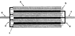
- FIG. 1 is a schematic cross-sectional view showing a structure of an electrode element included in a laminated laminate type secondary battery.
- This electrode element is formed by alternately stacking a plurality of positive electrodes c and a plurality of negative electrodes a with a separator b interposed therebetween.
- the positive electrode current collector e of each positive electrode c is welded to and electrically connected to each other at an end portion not covered with the positive electrode active material, and a positive electrode terminal f is welded to the welded portion.
- the negative electrode current collector d of each negative electrode a is welded and electrically connected to each other at an end portion not covered with the negative electrode active material, and a negative electrode terminal g is welded to the welded portion.
- the electrode element having such a planar laminated structure does not have a portion with a small R (a region close to the winding core of the wound structure), the electrode element associated with charge / discharge is compared with an electrode element having a wound structure.
- the generated gas may easily stay between the electrodes.
- Example 1 ⁇ Negative electrode>
- the negative electrode active material single silicon having an average particle diameter D50 measured by a laser diffraction / scattering method of 5 ⁇ m was used. A mass of 75: 20: 5 of this negative electrode active material, polyamideimide (trade name: Viromax (registered trademark) manufactured by Toyobo Co., Ltd.) as a binder for negative electrode, and acetylene black as a conductive auxiliary material Weighed ratios and mixed them with n-methylpyrrolidone to prepare a negative electrode slurry. The negative electrode slurry was applied to a copper foil having a thickness of 10 ⁇ m, dried, and further subjected to a heat treatment in a nitrogen atmosphere at 300 ° C. to produce a negative electrode.
- polyamideimide trade name: Viromax (registered trademark) manufactured by Toyobo Co., Ltd.
- acetylene black as a conductive auxiliary material
- ⁇ Positive electrode> A mass ratio of lithium nickelate (LiNi 0.80 Co 0.15 Al 0.05 O 2 ) as a positive electrode active material, carbon black as a conductive auxiliary material, and polyvinylidene fluoride as a positive electrode binder is 90: 5: 5 Weighed with. These materials were mixed with n-methylpyrrolidone to prepare a positive electrode slurry. The positive electrode slurry was applied to an aluminum foil having a thickness of 20 ⁇ m, dried, and further pressed to produce a positive electrode.
- Electrode element> The obtained positive electrode 3 layers and negative electrode 4 layers were alternately stacked while sandwiching a polypropylene porous film as a separator. The ends of the positive electrode current collector not covered with the positive electrode active material and the negative electrode current collector not covered with the negative electrode active material were welded. Furthermore, the positive electrode terminal made from aluminum and the negative electrode terminal made from nickel were each welded to the welding location, and the electrode element which has a planar laminated structure was obtained.
- a mixed solvent LiPF 6 as a supporting salt was mixed with the mixed solvent so as to be 1 mol / l to obtain an electrolytic solution.
- the content of the chain fluorinated sulfone compound is 10% by volume.
- ⁇ Secondary battery> The electrode element was wrapped with an aluminum laminate film as an outer package, an electrolyte solution was poured therein, and then sealed while reducing the pressure to 0.1 atm. Thus, a secondary battery was produced.
- “Cycle maintenance rate (%)” was calculated by (discharge capacity after 125 cycles) / (discharge capacity after 5 cycles) ⁇ 100 (unit:%).
- the “resistance change rate (%)” was calculated by (resistance value after 125 cycles) / (initial resistance value) ⁇ 100 (unit:%).
- the initial resistance value is the resistance value in the discharge state before the cycle.
- the resistance value was measured with an AC milliohm HiTester 3560 manufactured by HIOKI.
- volume increase (%) was calculated by ⁇ (volume capacity after 125 cycles) / (volume capacity before cycles) ⁇ 1 ⁇ ⁇ 100 (unit:%).
- Example 2 to 13 A secondary battery was prepared and evaluated in the same manner as in Example 1 except that the compounds listed in Table 1 were used as the chain fluorinated sulfone compound. The results are shown in Table 1.
- Example 1 the initial resistance value was 17.8 m ⁇ , and the resistance value after 125 cycles was 55.2 m ⁇ . In Example 4, the initial resistance value was 16.6 m ⁇ , and the resistance value after 125 cycles was 52.1 m ⁇ . In Comparative Example 1, the initial resistance value was 22.7 m ⁇ , and the resistance value after 125 cycles was 80.1 m ⁇ .
- Example 14 A secondary battery was prepared and evaluated in the same manner as in Example 1 except that a Si / SiO / C composite (CVD method) was used as the negative electrode active material instead of single silicon. The results are shown in Table 1.
- the Si / SiO / C composite (CVD method) was obtained by performing a CVD process at 1150 ° C. for 6 hours in an atmosphere containing methane gas.
- the Si / SiO / C composite had a form in which the surface of particles composed of silicon and silicon oxide was coated with carbon. Silicon was nanoclustered in silicon oxide.
- the mass ratio of Si / SiO / C was adjusted to be approximately 29/61/10.
- the average particle diameter D 50 of the Si / SiO / C composite was about 5 [mu] m.
- Example 15 to 26 A secondary battery was prepared and evaluated in the same manner as in Example 14 except that the compounds listed in Table 2 were used as the chain fluorinated sulfone compound. The results are shown in Table 2.
- Example 27 to 30 A secondary battery was prepared and evaluated in the same manner as in Example 17 except that the content (volume%) of the chain fluorinated sulfone compound in the mixed solvent was changed to the value shown in Table 3. The results are shown in Table 3.
- Example 31 A secondary battery was prepared and evaluated in the same manner as in Example 1 except that a SiSn alloy was used in place of elemental silicon as the negative electrode active material. The results are shown in Table 4.
- the average particle diameter D 50 of SiSn alloy was about 5 [mu] m.
- the SiSn alloy was obtained by mixing metal Si particles having an average particle diameter D50 of about 7 ⁇ m and metal Sn particles having an average particle diameter D50 of about 7 ⁇ m by a so-called mechanical milling method for 8 hours.
- Example 32 and 33 A secondary battery was prepared and evaluated in the same manner as in Example 31 except that the compounds listed in Table 4 were used as the chain fluorinated sulfone compound. The results are shown in Table 4.
- Example 34 A secondary battery was prepared and evaluated in the same manner as in Example 1 except that a Si / SiO / C composite (mechanical method) was used in place of elemental silicon as the negative electrode active material. The results are shown in Table 1.
- the Si / SiO / C composite (mechanical method) was produced by the following method. First, a mass ratio of 29:61:10 of silicon having an average particle diameter of 5 ⁇ m, amorphous silicon oxide (SiO x , 0 ⁇ x ⁇ 2) having an average particle diameter of 13 ⁇ m, and graphite having an average particle diameter of 30 ⁇ m. Weighed with. These materials were mixed for 24 hours by so-called mechanical milling to obtain a Si / SiO / C composite (mechanical method). In this negative electrode active material, silicon was dispersed in silicon oxide (SiO x , 0 ⁇ x ⁇ 2).
- Example 35 A secondary battery was produced and evaluated in the same manner as in Example 17 except that polyimide (manufactured by Ube Industries, trade name: U Varnish A) was used as the binder resin. The results are shown in Table 4.
- Example 36 A secondary battery was produced and evaluated in the same manner as in Example 14 except that the electrolytic solution prepared as follows was used. The results are shown in Table 5.
- LiPF 6 as a supporting salt was mixed with the mixed solvent so as to be 1 mol / l to obtain an electrolytic solution.
- Examples 37 to 48 A secondary battery was prepared and evaluated in the same manner as in Example 36 except that the compounds shown in Table 5 were used as the chain fluorinated sulfone compound. The results are shown in Table 5.
- Example 36 the initial resistance value was 40.4 m ⁇ , and the resistance value after 125 cycles was 58.5 m ⁇ .
- the initial resistance value was 41.8 m ⁇ , and the resistance value after 125 cycles was 48.5 m ⁇ .
- Example 49 A secondary battery was made and evaluated in the same manner as in Example 39 except that the content (volume%) of the chain fluorinated ether in the mixed solvent was changed to the value shown in Table 6. The results are shown in Table 6.
- Example 54 A secondary battery was prepared and evaluated in the same manner as in Example 39 except that the compounds shown in Table 7 were used as the chain fluorinated ether. The results are shown in Table 7.
- This embodiment can be used in all industrial fields that require a power source and in industrial fields related to the transport, storage, and supply of electrical energy.
- power supplies for mobile devices such as mobile phones and notebook computers
- power supplies for transportation and transportation media such as trains, satellites, and submarines, including electric vehicles such as electric cars, hybrid cars, electric bikes, and electric assist bicycles
- a backup power source such as a UPS
- a power storage facility for storing power generated by solar power generation, wind power generation, etc .
Abstract
Description
正極と、負極と、電解液と、を備える二次電池であって、
前記電解液が、下記式(1)で表される鎖状フッ素化スルホン化合物を含むことを特徴とする二次電池である。

上記式(1)で表される鎖状フッ素化スルホン化合物を含むことを特徴とする二次電池用電解液である。
本実施形態における電解液は、下記式(1)で表される鎖状フッ素化スルホン化合物を含む。鎖状フッ素化スルホン化合物を含む電解液を用いることにより、負極表面に安定な被膜(いわゆる、固体液体界面被膜、SEI被膜)を形成し、電池特性の劣化を抑制することが出来ると推測される。すなわち、反応性の高い鎖状フッ素化スルホン化合物が選択的に負極表面と反応して安定な皮膜を形成することで、負極における電解液の分解に伴うガスの発生が有効に抑制され、高温環境下での電池特性の劣化を抑制しているものと推測される。

(式(3)中、nは1~8であり、Y1~Y8は、それぞれ独立に、フッ素原子または水素原子である。ただし、Y1~Y3の少なくとも1つはフッ素原子であり、Y4~Y8の少なくとも一つはフッ素原子である。)。
式(4)において、nは1、2、3または4である。X1~X8は、それぞれ独立に、フッ素原子または水素原子である。ただし、X1~X4の少なくとも1つはフッ素原子であり、X5~X8の少なくとも1つはフッ素原子である。X1~X4は、n毎にそれぞれ独立していてもよい。
本実施形態のリチウム二次電池は、負極活物質を有する負極を備える。負極活物質は負極用結着材によって負極集電体上に結着されることができる。
正極は、例えば、正極活物質が正極用結着剤によって正極集電体を覆うように結着されてなる。
セパレータとしては、ポリプロピレン、ポリエチレン等の多孔質フィルムや不織布を用いることができる。また、セパレータとしては、それらを積層したものを用いることもできる。
外装体としては、電解液に安定で、かつ十分な水蒸気バリア性を持つものであれば、適宜選択することができる。例えば、積層ラミネート型の二次電池の場合、外装体としては、アルミニウム、シリカをコーティングしたポリプロピレン、ポリエチレン等のラミネートフィルムを用いることができる。特に、体積膨張を抑制する観点から、アルミニウムラミネートフィルムを用いることが好ましい。
本実施形態に係る二次電池の構成は、特に制限されるものではなく、例えば、正極および負極が対向配置された電極素子と、電解液とが外装体に内包されている構成とすることができる。二次電池の形状は、特に制限されるものではないが、例えば、円筒型、扁平捲回角型、積層角型、コイン型、扁平捲回ラミネート型、又は積層ラミネート型が挙げられる。
以下、本実施形態を実施例により具体的に説明する。
<負極>
負極活物質として、レーザ回折・散乱法により測定される平均粒径D50が5μmとなるように調整された単体ケイ素を用いた。この負極活物質と、負極用結着剤としてのポリアミドイミド(東洋紡績株式会社製、商品名:バイロマックス(登録商標))と、導電補助材としてのアセチレンブラックを、75:20:5の質量比で計量し、それらをn-メチルピロリドンと混合して、負極スラリーを調製した。負極スラリーを厚さ10μmの銅箔に塗布した後に乾燥し、さらに窒素雰囲気300℃の熱処理を行うことで、負極を作製した。
正極活物質としてのニッケル酸リチウム(LiNi0.80Co0.15Al0.05O2)と、導電補助材としてのカーボンブラックと、正極用結着剤としてのポリフッ化ビニリデンとを、90:5:5の質量比で計量した。そして、これら材料をn-メチルピロリドンと混合して、正極スラリーを調製した。正極スラリーを厚さ20μmのアルミ箔に塗布した後に乾燥し、さらにプレスすることで、正極を作製した。
得られた正極の3層と負極の4層を、セパレータとしてのポリプロピレン多孔質フィルムを挟みつつ交互に重ねた。正極活物質に覆われていない正極集電体および負極活物質に覆われていない負極集電体の端部をそれぞれ溶接した。さらに、その溶接箇所に、アルミニウム製の正極端子およびニッケル製の負極端子をそれぞれ溶接して、平面的な積層構造を有する電極素子を得た。
カーボネート系非水溶媒と、式(1)で表される鎖状フッ素化スルホン化合物(R1=CH2F-、R2=CH3-)と、を90:10(体積比)で混合して混合溶媒を調製した。該混合溶媒に、支持塩としてのLiPF6を1モル/lとなるように混合して電解液を得た。なお、カーボネート系非水溶媒としてEC/PC/DMC/EMC/DEC=20/20/20/20/20(体積比)の溶媒を用いた。なお、調製した混合溶媒において、鎖状フッ素化スルホン化合物の含有量は10体積%である。
上記電極素子を外装体としてのアルミニウムラミネートフィルムで包み、内部に電解液を注液した後、0.1気圧まで減圧しつつ封止することで、二次電池を作製した。
(55℃におけるサイクル特性、抵抗変化率、体積増加)
作製した二次電池に対し、55℃に保った恒温槽中で、2.5Vから4.1Vの電圧範囲で充放電を繰り返す試験を行い、サイクル維持率(%)、抵抗変化率(%)及び体積増加(%)について評価した。充電は、1Cで4.1Vまで充電した後、合計で2.5時間定電圧充電を行った。放電は、1Cで2.5Vまで定電流放電した。結果を表1に示す。
鎖状フッ素化スルホン化合物として表1に記載の化合物を用いた以外は、実施例1と同様に二次電池を作製し、評価した。結果を表1に示す。
鎖状フッ素化スルホン化合物を用いなかった以外、は実施例1と同様に二次電池を作製し、評価した。結果を表1に示す。
鎖状フッ素化スルホン化合物を用いず、代わりに表1に記載の鎖状スルホン化合物を用いた以外は、実施例1と同様に二次電池を作製し、評価した。結果を表1に示す。

負極活物質として、単体ケイ素の代わりにSi/SiO/C複合体(CVD法)を用いた以外は、実施例1と同様に二次電池を作製し、評価した。結果を表1に示す。
鎖状フッ素化スルホン化合物として表2に記載の化合物を用いた以外は、実施例14と同様に二次電池を作製し、評価した。結果を表2に示す。

鎖状フッ素化スルホン化合物の混合溶媒中の含有量(体積%)を表3に示した値とした以外は、実施例17と同様に二次電池を作製し、評価した。結果を表3に示す。

負極活物質として、単体ケイ素の代わりにSiSn合金を用いた以外は、実施例1と同様に二次電池を作製し、評価した。結果を表4に示す。SiSn合金の平均粒径D50は約5μmであった。SiSn合金は、平均粒径D50は約7μmの金属Si粒子と、平均粒径D50は約7μmの金属Sn粒子を、いわゆるメカニカルミリング法にて8h混合することによって得た。
鎖状フッ素化スルホン化合物として表4に記載の化合物を用いた以外は、実施例31と同様に二次電池を作製し、評価した。結果を表4に示す。
負極活物質として、単体ケイ素の代わりにSi/SiO/C複合体(メカニカル法)を用いた以外は、実施例1と同様に二次電池を作製し、評価した。結果を表1に示す。
バインダ樹脂としてポリイミド(宇部興産株式会社製、商品名:UワニスA)を用いた以外は、実施例17と同様にして二次電池を作製し、評価した。結果を表4に示す。

以下のように調製した電解液を用いた以外は、実施例14と同様にして二次電池を作製し、評価した。結果を表5に示す。
鎖状フッ素化スルホン化合物として表5に記載の化合物を用いた以外は、実施例36と同様に二次電池を作製し、評価した。結果を表5に示す。

鎖状フッ素化エーテルの混合溶媒中の含有量(体積%)を表6に示す値とした以外は、実施例39と同様にして二次電池を作製し、評価した。結果を表6に示す。

鎖状フッ素化エーテルとして表7に示す化合物を用いた以外は、実施例39と同様にして二次電池を作製し、評価した。結果を表7に示す。

b セパレータ
c 正極
d 負極集電体
e 正極集電体
f 正極端子
g 負極端子
Claims (24)
- 正極と、負極活物質を含む負極と、電解液と、を備える二次電池であって、
前記電解液が、下記式(1)で表される鎖状フッ素化スルホン化合物を含むことを特徴とする二次電池;

- R1及びR2の少なくとも一つがフッ素置換アルキル基である請求項1に記載の二次電池。
- R1及びR2は、それぞれ独立に、フッ素置換アルキル基である請求項2に記載の二次電池。
- R1及びR2の一方が炭素数1~6のフッ素置換アルキル基であり、他方がアリール基で置換されていてもよい炭素数1~6のアルキル基、又はアルキル基で置換されていてもよい炭素数6~10のアリール基である請求項2に記載の二次電池。
- 前記電解液が、さらに、下記式(2)で表される鎖状フッ素化エーテル化合物を含有する請求項1乃至4のいずれかに記載の二次電池;

- 前記鎖状フッ素化エーテル化合物は、下記式(3)で表される請求項5に記載の二次電池;
H-(CX1X2-CX3X4)n-CH2O-CX5X6-CX7X8-H (3)
(式(3)において、nは1、2、3または4であり、X1~X8は、それぞれ独立に、フッ素原子または水素原子である。ただし、X1~X4の少なくとも1つはフッ素原子であり、X5~X8の少なくとも1つはフッ素原子である。)。 - 前記電解液は、さらに、カーボネート化合物を含む請求項5又は6に記載の二次電池。
- 前記鎖状フッ素化スルホン化合物の含有量が前記鎖状フッ素化スルホン化合物と前記鎖状フッ素化エーテル化合物と溶媒との総量に対して1~15体積%であり、
前記鎖状フッ素化エーテル化合物の含有量が前記鎖状フッ素化スルホン化合物と前記鎖状フッ素化エーテル化合物と溶媒との総量に対して10~35体積%であり、
前記カーボネート化合物の含有量が前記鎖状フッ素化スルホン化合物と前記鎖状フッ素化エーテル化合物と溶媒との総量に対して30~89体積%である請求項8に記載の二次電池。 - 前記負極活物質がリチウムと合金可能な金属(a)を含む請求項1乃至8のいずれかに記載の二次電池。
- 前記金属(a)がシリコンである請求項9に記載の二次電池。
- 前記負極活物質が、さらに、リチウムイオンを吸蔵、放出し得る金属酸化物(b)、及びリチウムイオンを吸蔵、放出し得る炭素材料(c)を含む請求項9又は10に記載の二次電池。
- 前記金属(a)がシリコンであり、前記金属酸化物(b)がシリコン酸化物である請求項11に記載の二次電池。
- 前記シリコン酸化物の少なくとも一部がアモルファス構造を有し、前記シリコンの少なくとも一部が前記シリコン酸化物中に分散している請求項12に記載の二次電池。
- 前記負極は結着剤を含み、該結着剤が、ポリイミドまたはポリアミドイミドである請求項1乃至13のいずれかに記載の二次電池。
- 積層ラミネート構造を有する請求項1乃至14のいずれかに記載の二次電池。
- 前記外装体がアルミニウムラミネートフィルムである請求項15に記載の二次電池。
- 下記式(1)で表される鎖状フッ素化スルホン化合物を含むことを特徴とする二次電池用電解液;

- R1及びR2の少なくとも一つがフッ素置換アルキル基である請求項17に記載の二次電池用電解液。
- R1及びR2は、それぞれ独立に、フッ素置換アルキル基である請求項18に記載の二次電池用電解液。
- R1及びR2の一方が炭素数1~6のフッ素置換アルキル基であり、他方がアリール基で置換されていてもよい炭素数1~6のアルキル基、又はアルキル基で置換されていてもよい炭素数6~10のアリール基である請求項18に記載の二次電池用電解液。
- 前記電解液が、さらに、下記式(2)で表される鎖状フッ素化エーテル化合物を含有する請求項17乃至20のいずれかに記載の二次電池用電解液;

- 前記鎖状フッ素化エーテルは、下記式(3)で表される請求項21に記載の二次電池用電解液;
H-(CX1X2-CX3X4)n-CH2O-CX5X6-CX7X8-H (3)
(式(3)において、nは1、2、3または4であり、X1~X8は、それぞれ独立に、フッ素原子または水素原子である。ただし、X1~X4の少なくとも1つはフッ素原子であり、X5~X8の少なくとも1つはフッ素原子である。)。 - 前記電解液は、さらに、カーボネート化合物を含む請求項21又は22に記載の二次電池用電解液。
- 前記鎖状フッ素化スルホン化合物の含有量が前記鎖状フッ素化スルホン化合物と前記鎖状フッ素化エーテル化合物と溶媒との総量に対して1~15体積%であり、
前記鎖状フッ素化エーテル化合物の含有量が前記鎖状フッ素化スルホン化合物と前記鎖状フッ素化エーテル化合物と溶媒との総量に対して10~35体積%であり、
前記カーボネート化合物の含有量が前記鎖状フッ素化スルホン化合物と前記鎖状フッ素化エーテル化合物と溶媒との総量に対して30~89体積%である請求項23に記載の二次電池用電解液。
Priority Applications (3)
| Application Number | Priority Date | Filing Date | Title |
|---|---|---|---|
| US14/004,347 US9373867B2 (en) | 2011-03-28 | 2011-09-27 | Secondary battery and electrolyte liquid |
| JP2013507035A JP6070540B2 (ja) | 2011-03-28 | 2011-09-27 | 二次電池および電解液 |
| CN201180069587.6A CN103443991B (zh) | 2011-03-28 | 2011-09-27 | 二次电池和电解液 |
Applications Claiming Priority (2)
| Application Number | Priority Date | Filing Date | Title |
|---|---|---|---|
| JP2011070108 | 2011-03-28 | ||
| JP2011-070108 | 2011-03-28 |
Publications (1)
| Publication Number | Publication Date |
|---|---|
| WO2012132059A1 true WO2012132059A1 (ja) | 2012-10-04 |
Family
ID=46929867
Family Applications (1)
| Application Number | Title | Priority Date | Filing Date |
|---|---|---|---|
| PCT/JP2011/072034 WO2012132059A1 (ja) | 2011-03-28 | 2011-09-27 | 二次電池および電解液 |
Country Status (4)
| Country | Link |
|---|---|
| US (1) | US9373867B2 (ja) |
| JP (1) | JP6070540B2 (ja) |
| CN (1) | CN103443991B (ja) |
| WO (1) | WO2012132059A1 (ja) |
Cited By (11)
| Publication number | Priority date | Publication date | Assignee | Title |
|---|---|---|---|---|
| WO2015003725A1 (en) | 2013-07-09 | 2015-01-15 | Friedrich-Schiller-Universität Jena | Electroactive polymers, manufacturing process thereof, electrode and use thereof |
| WO2015051141A1 (en) * | 2013-10-04 | 2015-04-09 | E. I. Du Pont De Nemours And Company | Methods for preparation of fluorinated sulfur-containing compounds |
| US9673450B2 (en) | 2011-09-02 | 2017-06-06 | Solvay Sa | Lithium ion battery |
| KR20170111745A (ko) * | 2016-03-29 | 2017-10-12 | 주식회사 엘지화학 | 비수성 전해액, 이를 포함하는 리튬 이차전지 및 이의 제조방법 |
| US9979050B2 (en) | 2011-09-02 | 2018-05-22 | Solvay Sa | Fluorinated electrolyte compositions |
| US10044066B2 (en) | 2012-06-01 | 2018-08-07 | Solvary SA | Fluorinated electrolyte compositions |
| US10074874B2 (en) | 2012-06-01 | 2018-09-11 | Solvay Sa | Additives to improve electrolyte performance in lithium ion batteries |
| US10243234B2 (en) * | 2014-10-24 | 2019-03-26 | Nec Corporation | Secondary battery |
| JP2019523521A (ja) * | 2016-06-03 | 2019-08-22 | ソルヴェイ(ソシエテ アノニム) | フッ素化スルホンを含む非水電解質組成物 |
| US10587008B2 (en) | 2013-11-28 | 2020-03-10 | Nec Corporation | Electrolyte solution for secondary battery and secondary battery using same |
| US10686220B2 (en) | 2013-04-04 | 2020-06-16 | Solvay Sa | Nonaqueous electrolyte compositions |
Families Citing this family (28)
| Publication number | Priority date | Publication date | Assignee | Title |
|---|---|---|---|---|
| JP2010133696A (ja) * | 2008-11-06 | 2010-06-17 | Kobe Steel Ltd | 蒸気圧縮装置 |
| US10957898B2 (en) | 2018-12-21 | 2021-03-23 | Enevate Corporation | Silicon-based energy storage devices with anhydride containing electrolyte additives |
| DE102012105377B4 (de) * | 2012-06-20 | 2018-11-15 | Jacobs University Bremen Ggmbh | 1,2,4-thiadiazinan-3,5-dion-1,1-dioxid-derivate, deren herstellung und verwendung |
| CN104953177A (zh) * | 2014-03-26 | 2015-09-30 | 中国科学院福建物质结构研究所 | 一种高温型锂电池电解液 |
| EP3353844B1 (en) | 2015-03-27 | 2022-05-11 | Mason K. Harrup | All-inorganic solvents for electrolytes |
| DE102015208197B3 (de) * | 2015-05-04 | 2016-08-11 | Fraunhofer-Gesellschaft zur Förderung der angewandten Forschung e.V. | Elektrolyt für eine Alkali-Schwefel-Batterie, Alkali-Schwefel-Batterie enthaltend den Elektrolyten und Verwendungen ihrer Bestandteile |
| CN105895958A (zh) * | 2016-06-29 | 2016-08-24 | 宁德时代新能源科技股份有限公司 | 一种电解液及锂离子电池 |
| US10707531B1 (en) | 2016-09-27 | 2020-07-07 | New Dominion Enterprises Inc. | All-inorganic solvents for electrolytes |
| JP6593305B2 (ja) * | 2016-11-09 | 2019-10-23 | 株式会社村田製作所 | 二次電池用電解液、二次電池、電池パック、電動車両、電力貯蔵システム、電動工具および電子機器 |
| WO2018101391A1 (ja) * | 2016-12-02 | 2018-06-07 | 日本電気株式会社 | リチウムイオン二次電池 |
| US10811727B2 (en) | 2017-12-07 | 2020-10-20 | Enevate Corporation | Silicon-based energy storage devices with ether containing electrolyte additives |
| US11075408B2 (en) | 2017-12-07 | 2021-07-27 | Enevate Corporation | Silicon-based energy storage devices with fluorinated polymer containing electrolyte additives |
| WO2019113518A1 (en) | 2017-12-07 | 2019-06-13 | Enevate Corporation | Silicon-based energy storage devices with linear carbonate containing electrolyte additives |
| US10978739B2 (en) | 2017-12-07 | 2021-04-13 | Enevate Corporation | Silicon-based energy storage devices with carboxylic ether, carboxylic acid based salt, or acrylate electrolyte containing electrolyte additives |
| US11283069B2 (en) | 2017-12-07 | 2022-03-22 | Enevate Corporation | Silicon-based energy storage devices with fluorinated cyclic compound containing electrolyte additives |
| US10847839B2 (en) | 2018-08-01 | 2020-11-24 | Uchicago Argonne, Llc | Non-aqueous electrolytes for lithium batteries |
| CN110970659B (zh) | 2018-09-28 | 2021-03-09 | 宁德时代新能源科技股份有限公司 | 非水电解液及锂离子电池 |
| CN110970652A (zh) * | 2018-09-28 | 2020-04-07 | 宁德时代新能源科技股份有限公司 | 非水电解液及锂离子电池 |
| CN110970658B (zh) * | 2018-09-28 | 2021-08-06 | 宁德时代新能源科技股份有限公司 | 锂离子电池 |
| CN110970660A (zh) * | 2018-09-28 | 2020-04-07 | 宁德时代新能源科技股份有限公司 | 非水电解液及锂离子电池 |
| CN110970663A (zh) * | 2018-09-28 | 2020-04-07 | 宁德时代新能源科技股份有限公司 | 非水电解液及锂离子电池 |
| CN110970661A (zh) * | 2018-09-28 | 2020-04-07 | 宁德时代新能源科技股份有限公司 | 非水电解液及锂离子电池 |
| US11165099B2 (en) | 2018-12-21 | 2021-11-02 | Enevate Corporation | Silicon-based energy storage devices with cyclic organosilicon containing electrolyte additives |
| US10964975B2 (en) | 2019-01-17 | 2021-03-30 | Uchicago Argonne, Llc | Electrolytes for lithium-ion batteries |
| US10978741B2 (en) | 2019-02-04 | 2021-04-13 | Uchicago Argonne, Llc | Non-aqueous electrolytes for electrochemical cells |
| US11398641B2 (en) | 2019-06-05 | 2022-07-26 | Enevate Corporation | Silicon-based energy storage devices with silicon containing electrolyte additives |
| CN110854432B (zh) * | 2019-11-05 | 2021-06-29 | 宁德新能源科技有限公司 | 电解液以及使用其的电化学装置和电子装置 |
| CN114256508A (zh) * | 2022-01-14 | 2022-03-29 | 南方科技大学 | 一种非水电解液以及二次电池 |
Citations (5)
| Publication number | Priority date | Publication date | Assignee | Title |
|---|---|---|---|---|
| JPH1126015A (ja) * | 1997-06-30 | 1999-01-29 | Daikin Ind Ltd | 非水電解液電池用電解液およびこれを用いた非水電解液電池 |
| JPH11126632A (ja) * | 1997-08-29 | 1999-05-11 | Alcatel Cit | 有機電解質と炭素アノードを備えるリチウム蓄電池 |
| JP2001223024A (ja) * | 2000-01-21 | 2001-08-17 | Samsung Sdi Co Ltd | リチウム二次電池用電解液 |
| JP2006114285A (ja) * | 2004-10-13 | 2006-04-27 | Samsung Sdi Co Ltd | リチウム二次電池用の非水電解液およびリチウム二次電池および二次電池システム |
| JP2010123287A (ja) * | 2008-11-17 | 2010-06-03 | Panasonic Corp | 非水電解液および非水電解液二次電池 |
Family Cites Families (16)
| Publication number | Priority date | Publication date | Assignee | Title |
|---|---|---|---|---|
| JP2997741B2 (ja) | 1992-07-29 | 2000-01-11 | セイコーインスツルメンツ株式会社 | 非水電解質二次電池及びその製造方法 |
| US6245465B1 (en) * | 1997-10-15 | 2001-06-12 | Moltech Corporation | Non-aqueous electrolyte solvents for secondary cells |
| JP2000021447A (ja) | 1998-07-03 | 2000-01-21 | Japan Storage Battery Co Ltd | 非水電解質電池 |
| DE19858924A1 (de) * | 1998-12-19 | 2000-06-21 | Aventis Res & Tech Gmbh & Co | Elektrolytsystem für Lithiumbatterien und dessen Verwendung sowie Verfahren zur Erhöhung |
| JP3982230B2 (ja) | 2001-10-18 | 2007-09-26 | 日本電気株式会社 | 二次電池用負極およびそれを用いた二次電池 |
| JP3952180B2 (ja) | 2002-05-17 | 2007-08-01 | 信越化学工業株式会社 | 導電性珪素複合体及びその製造方法並びに非水電解質二次電池用負極材 |
| US7229718B2 (en) * | 2002-08-22 | 2007-06-12 | Samsung Sdi Co., Ltd. | Electrolyte for rechargeable lithium battery and rechargeable lithium battery comprising same |
| JP4519592B2 (ja) * | 2004-09-24 | 2010-08-04 | 株式会社東芝 | 非水電解質二次電池用負極活物質及び非水電解質二次電池 |
| JP4284541B2 (ja) * | 2004-12-14 | 2009-06-24 | ソニー株式会社 | 二次電池 |
| JP4942319B2 (ja) * | 2005-09-07 | 2012-05-30 | 三洋電機株式会社 | リチウム二次電池 |
| KR100948970B1 (ko) * | 2006-03-13 | 2010-03-23 | 주식회사 엘지화학 | 완충부재가 설치되어 있는 중대형 전지모듈 |
| JP2007273320A (ja) * | 2006-03-31 | 2007-10-18 | Sanyo Electric Co Ltd | リチウム二次電池 |
| KR100895202B1 (ko) * | 2006-04-17 | 2009-05-06 | 주식회사 엘지화학 | 파우치형 전지 |
| JP2008066047A (ja) * | 2006-09-06 | 2008-03-21 | Matsushita Electric Ind Co Ltd | 非水電解質電池およびそのセパレータ |
| JP2008192504A (ja) | 2007-02-06 | 2008-08-21 | Daikin Ind Ltd | 非水系電解液 |
| CN101752547B (zh) * | 2008-12-18 | 2012-05-30 | 中国电子科技集团公司第十八研究所 | 具有核壳结构的锂离子二次电池负极材料制备方法 |
-
2011
- 2011-09-27 US US14/004,347 patent/US9373867B2/en active Active
- 2011-09-27 JP JP2013507035A patent/JP6070540B2/ja not_active Expired - Fee Related
- 2011-09-27 CN CN201180069587.6A patent/CN103443991B/zh active Active
- 2011-09-27 WO PCT/JP2011/072034 patent/WO2012132059A1/ja active Application Filing
Patent Citations (5)
| Publication number | Priority date | Publication date | Assignee | Title |
|---|---|---|---|---|
| JPH1126015A (ja) * | 1997-06-30 | 1999-01-29 | Daikin Ind Ltd | 非水電解液電池用電解液およびこれを用いた非水電解液電池 |
| JPH11126632A (ja) * | 1997-08-29 | 1999-05-11 | Alcatel Cit | 有機電解質と炭素アノードを備えるリチウム蓄電池 |
| JP2001223024A (ja) * | 2000-01-21 | 2001-08-17 | Samsung Sdi Co Ltd | リチウム二次電池用電解液 |
| JP2006114285A (ja) * | 2004-10-13 | 2006-04-27 | Samsung Sdi Co Ltd | リチウム二次電池用の非水電解液およびリチウム二次電池および二次電池システム |
| JP2010123287A (ja) * | 2008-11-17 | 2010-06-03 | Panasonic Corp | 非水電解液および非水電解液二次電池 |
Cited By (14)
| Publication number | Priority date | Publication date | Assignee | Title |
|---|---|---|---|---|
| US9673450B2 (en) | 2011-09-02 | 2017-06-06 | Solvay Sa | Lithium ion battery |
| US9979050B2 (en) | 2011-09-02 | 2018-05-22 | Solvay Sa | Fluorinated electrolyte compositions |
| US10044066B2 (en) | 2012-06-01 | 2018-08-07 | Solvary SA | Fluorinated electrolyte compositions |
| US10074874B2 (en) | 2012-06-01 | 2018-09-11 | Solvay Sa | Additives to improve electrolyte performance in lithium ion batteries |
| US10686220B2 (en) | 2013-04-04 | 2020-06-16 | Solvay Sa | Nonaqueous electrolyte compositions |
| US10916805B2 (en) | 2013-04-04 | 2021-02-09 | Solvay Sa | Nonaqueous electrolyte compositions |
| WO2015003725A1 (en) | 2013-07-09 | 2015-01-15 | Friedrich-Schiller-Universität Jena | Electroactive polymers, manufacturing process thereof, electrode and use thereof |
| US10103384B2 (en) | 2013-07-09 | 2018-10-16 | Evonik Degussa Gmbh | Electroactive polymers, manufacturing process thereof, electrode and use thereof |
| WO2015051141A1 (en) * | 2013-10-04 | 2015-04-09 | E. I. Du Pont De Nemours And Company | Methods for preparation of fluorinated sulfur-containing compounds |
| US10587008B2 (en) | 2013-11-28 | 2020-03-10 | Nec Corporation | Electrolyte solution for secondary battery and secondary battery using same |
| US10243234B2 (en) * | 2014-10-24 | 2019-03-26 | Nec Corporation | Secondary battery |
| KR20170111745A (ko) * | 2016-03-29 | 2017-10-12 | 주식회사 엘지화학 | 비수성 전해액, 이를 포함하는 리튬 이차전지 및 이의 제조방법 |
| KR102143100B1 (ko) * | 2016-03-29 | 2020-08-10 | 주식회사 엘지화학 | 비수성 전해액, 이를 포함하는 리튬 이차전지 및 이의 제조방법 |
| JP2019523521A (ja) * | 2016-06-03 | 2019-08-22 | ソルヴェイ(ソシエテ アノニム) | フッ素化スルホンを含む非水電解質組成物 |
Also Published As
| Publication number | Publication date |
|---|---|
| US20140017559A1 (en) | 2014-01-16 |
| JP6070540B2 (ja) | 2017-02-01 |
| US9373867B2 (en) | 2016-06-21 |
| CN103443991B (zh) | 2015-12-16 |
| CN103443991A (zh) | 2013-12-11 |
| JPWO2012132059A1 (ja) | 2014-07-24 |
Similar Documents
| Publication | Publication Date | Title |
|---|---|---|
| JP6070540B2 (ja) | 二次電池および電解液 | |
| JP6191454B2 (ja) | 二次電池および電解液 | |
| JP5748193B2 (ja) | 二次電池 | |
| JP5704633B2 (ja) | 二次電池 | |
| JP5419188B2 (ja) | 非水電解液二次電池 | |
| WO2012056765A1 (ja) | 二次電池及びその製造方法 | |
| WO2013183522A1 (ja) | リチウムイオン二次電池 | |
| JP5867395B2 (ja) | 二次電池 | |
| JP5867399B2 (ja) | 二次電池 | |
| WO2012029551A1 (ja) | 二次電池およびそれに用いる二次電池用電解液 | |
| JP5867396B2 (ja) | 二次電池 | |
| JP5867397B2 (ja) | 二次電池 | |
| JP5920217B2 (ja) | 二次電池 | |
| WO2013038842A1 (ja) | 二次電池 | |
| WO2012029625A1 (ja) | 二次電池 | |
| JP5867398B2 (ja) | 二次電池 | |
| WO2012049889A1 (ja) | 二次電池およびそれに用いる二次電池用電解液 | |
| JP2012033346A (ja) | 非プロトン性電解液二次電池 | |
| WO2012029645A1 (ja) | 二次電池およびそれに用いる二次電池用電解液 | |
| WO2018096889A1 (ja) | 非水電解液、及びリチウムイオン二次電池 |
Legal Events
| Date | Code | Title | Description |
|---|---|---|---|
| 121 | Ep: the epo has been informed by wipo that ep was designated in this application |
Ref document number: 11862403 Country of ref document: EP Kind code of ref document: A1 |
|
| WWE | Wipo information: entry into national phase |
Ref document number: 14004347 Country of ref document: US |
|
| ENP | Entry into the national phase |
Ref document number: 2013507035 Country of ref document: JP Kind code of ref document: A |
|
| NENP | Non-entry into the national phase |
Ref country code: DE |
|
| 122 | Ep: pct application non-entry in european phase |
Ref document number: 11862403 Country of ref document: EP Kind code of ref document: A1 |