WO2012111776A1 - 自動二輪車用空気入りタイヤ - Google Patents
自動二輪車用空気入りタイヤ Download PDFInfo
- Publication number
- WO2012111776A1 WO2012111776A1 PCT/JP2012/053721 JP2012053721W WO2012111776A1 WO 2012111776 A1 WO2012111776 A1 WO 2012111776A1 JP 2012053721 W JP2012053721 W JP 2012053721W WO 2012111776 A1 WO2012111776 A1 WO 2012111776A1
- Authority
- WO
- WIPO (PCT)
- Prior art keywords
- rubber
- rubber layer
- cap
- base
- tire
- Prior art date
Links
Images

Classifications
-
- B—PERFORMING OPERATIONS; TRANSPORTING
- B60—VEHICLES IN GENERAL
- B60C—VEHICLE TYRES; TYRE INFLATION; TYRE CHANGING; CONNECTING VALVES TO INFLATABLE ELASTIC BODIES IN GENERAL; DEVICES OR ARRANGEMENTS RELATED TO TYRES
- B60C11/00—Tyre tread bands; Tread patterns; Anti-skid inserts
- B60C11/0041—Tyre tread bands; Tread patterns; Anti-skid inserts comprising different tread rubber layers
- B60C11/005—Tyre tread bands; Tread patterns; Anti-skid inserts comprising different tread rubber layers with cap and base layers
- B60C11/0058—Tyre tread bands; Tread patterns; Anti-skid inserts comprising different tread rubber layers with cap and base layers with different cap rubber layers in the axial direction
-
- B—PERFORMING OPERATIONS; TRANSPORTING
- B60—VEHICLES IN GENERAL
- B60C—VEHICLE TYRES; TYRE INFLATION; TYRE CHANGING; CONNECTING VALVES TO INFLATABLE ELASTIC BODIES IN GENERAL; DEVICES OR ARRANGEMENTS RELATED TO TYRES
- B60C11/00—Tyre tread bands; Tread patterns; Anti-skid inserts
- B60C11/0008—Tyre tread bands; Tread patterns; Anti-skid inserts characterised by the tread rubber
- B60C2011/0016—Physical properties or dimensions
- B60C2011/0025—Modulus or tan delta
-
- B—PERFORMING OPERATIONS; TRANSPORTING
- B60—VEHICLES IN GENERAL
- B60C—VEHICLE TYRES; TYRE INFLATION; TYRE CHANGING; CONNECTING VALVES TO INFLATABLE ELASTIC BODIES IN GENERAL; DEVICES OR ARRANGEMENTS RELATED TO TYRES
- B60C11/00—Tyre tread bands; Tread patterns; Anti-skid inserts
- B60C11/0008—Tyre tread bands; Tread patterns; Anti-skid inserts characterised by the tread rubber
- B60C2011/0016—Physical properties or dimensions
- B60C2011/0033—Thickness of the tread
-
- B—PERFORMING OPERATIONS; TRANSPORTING
- B60—VEHICLES IN GENERAL
- B60C—VEHICLE TYRES; TYRE INFLATION; TYRE CHANGING; CONNECTING VALVES TO INFLATABLE ELASTIC BODIES IN GENERAL; DEVICES OR ARRANGEMENTS RELATED TO TYRES
- B60C2200/00—Tyres specially adapted for particular applications
- B60C2200/10—Tyres specially adapted for particular applications for motorcycles, scooters or the like
Definitions
- the present invention relates to a pneumatic tire for a motorcycle (hereinafter, also simply referred to as “tire”), and more specifically, a groove in a shoulder portion while achieving a straight running stability, wear resistance, turning grip performance and turning stability in a well-balanced manner.
- the present invention relates to a pneumatic tire for a motorcycle that suppresses occurrence of bottom cracks.
- the tread part of a pneumatic tire for motorcycles has been provided with a highly stable compound with high stability in the crown center part in order to achieve both running stability and grip force when traveling straight, and the shoulder part.
- a structure in which a soft compound having a high grip force is arranged is adopted, and various studies have been made on such a structure.
- Patent Document 1 discloses that the center rubber is exposed on the tread surface for the purpose of improving straight running stability and wear resistance, and grip performance and turning stability when turning on a wet road surface.
- a tire has been proposed in which only the shoulder portion has a cap rubber (so-called cap / base structure), a hard rubber is used as the base rubber, and a soft rubber is used as the cap rubber.
- Patent Document 2 discloses a two-wheeled vehicle in which rubber having good wear resistance is disposed in the center portion, and a shoulder portion serving as a ground contact surface at the time of turning has a cap base structure to achieve both grip performance and turning stability at the time of turning. Auto tires have been proposed.
- Patent Document 3 a low loss tangent (tan ⁇ ) tread rubber is disposed continuously from the center portion through the carcass side of the shoulder portion or discontinuously excluding the shoulder portion, and the shoulder portion has a high loss.
- a tire for a two-wheeled vehicle in which a tangent (tan ⁇ ) tread rubber is arranged has been proposed.
- a shoulder portion of a pneumatic tire for a motorcycle is provided with a groove from the viewpoint of drainage.
- the gauge of the cap rubber at the groove bottom portion is 0. This results in a thin skin state of about 5 mm, and the rigidity of the rubber changes abruptly at the thin skin portion, so that the cap rubber portion at the bottom of the groove tends to crack.
- an object of the present invention is to provide a pneumatic tire for a motorcycle that suppresses the occurrence of groove bottom cracks in the shoulder portion while achieving a straight running stability, wear resistance, turning grip performance and turning stability in a well-balanced manner. There is.
- the present inventor has determined that the cap rubber layer thickness in the shoulder portion is within a predetermined range in a specific cap / base structure, so that straight running stability, wear resistance, swiveling It has been found that the occurrence of groove bottom cracks in the shoulder portion can be suppressed while achieving good grip performance and turning stability in a balanced manner, and the present invention has been completed.
- the pneumatic tire for a motorcycle of the present invention is a pneumatic tire for a motorcycle including a tread portion formed in an annular shape.
- the tread portion includes a center portion formed of a single base rubber layer, and a shoulder portion in which a base rubber layer and a cap rubber layer are sequentially laminated.
- the rubber of the cap rubber layer is more than the rubber of the base rubber layer.
- the cap rubber layer has a low hardness and a thickness of the cap rubber layer at the groove bottom of the shoulder portion is 1.0 mm or more.
- the hardness means Shore A hardness at 25 ° C., and can be measured using a commercially available hardness meter.
- the rubber of the cap rubber layer preferably has a lower hardness of 2 ° or more and less than 6 ° than the rubber of the base rubber layer, and the rubber of the cap rubber layer has a hardness of 6 ° or more lower than that of the rubber of the base rubber layer.
- the thickness of the cap rubber layer at the groove bottom of the shoulder portion is preferably 1.5 mm or more.
- the loss tangent tan ⁇ at 60 ° C. of the rubber of the cap rubber layer is 0.20 to 0.45, and tan ⁇ at 60 ° C. of the rubber of the base rubber layer is 0.05 to 0.00. 36 is preferred.
- FIG. 1 is a left half sectional view of a pneumatic tire for a motorcycle according to a preferred embodiment of the present invention.
- FIG. 1 is a left half sectional view of a motorcycle pneumatic tire according to a preferred embodiment of the present invention.
- the tire of the present invention includes a pair of bead portions 11, a pair of sidewall portions 12 connected thereto, and a tread portion 13 connected between both sidewall portions.
- a carcass made up of at least one layer, in the illustrated example, of two carcass plies 1 and a belt layer 2 that is disposed on the outer side in the tire radial direction and in which a reinforcing cord is spirally wound in the circumferential direction. is doing.
- the tread portion 13 is provided with a groove, and the broken line in the figure indicates the groove bottom 3.
- the tire of the present invention includes a center portion composed of a single layer of the base rubber layer 4 and a shoulder portion in which the base rubber layer 4 and the cap rubber layer 5 are sequentially laminated. That is, the base rubber layer 4 is exposed on the tread surface at the center portion.
- the rubber of the cap rubber layer 5 has a lower hardness than the rubber of the base rubber layer 4.
- the thickness of the cap rubber layer 5 is set to a predetermined thickness or more.
- the rubber of the cap rubber layer 5 has a lower hardness than the rubber of the base rubber layer 4, and the thickness d of the cap rubber layer 5 at the groove bottom of the shoulder portion is 1.0 mm or more.
- the rubber of the cap rubber layer 5 is made to have a hardness that is 2 ° or more and less than 6 ° lower than that of the rubber of the base rubber layer 4, and the thickness d of the cap rubber layer 5 at the groove bottom 3 of the shoulder portion is 1. 0.0 mm or more.
- the thickness d of the cap rubber layer 5 at the groove bottom of the shoulder portion is 1.5 mm.
- the hardness is preferably 6 to 14 ° low, and d is 1.5 to 2.5 mm.
- the hardness of the cap rubber and the base rubber can be realized by appropriately selecting a rubber composition and its filler according to a conventional method.
- the tan ⁇ at 60 ° C. of the rubber of the cap rubber layer 5 is 0.20 to 0.45, and the tan ⁇ at 60 ° C. of the rubber of the base rubber layer 4 is 0.05 to 0.36. It is preferable.
- the straight running stability, the wear resistance, the grip performance during turning, and the turning stability will be further improved. .
- the rubber thickness of the cap rubber layer 5 in the shoulder portion is preferably in the range of 10 to 30% with respect to the rubber thickness of the tread rubber.
- the cap rubber layer 5 can be made of silica-containing rubber when it is necessary to further improve the grip force on a wet road surface.
- the creepage length of the tread surface is preferably in the range of 20 to 50% with respect to the creepage length of the tread surface. That is, if the ratio is less than 20%, the straight running stability may be deteriorated. On the other hand, if the ratio exceeds 50%, the grip force during turning may be reduced.
- the belt layer 2 is formed by spirally winding a long rubber-coated cord (not shown) in which one cord is covered with rubber or a belt-like ply (not shown) in which a plurality of cords are covered with rubber.
- a so-called spiral belt which is formed by turning and the cord direction is substantially the tire circumferential direction can be suitably used.
- aromatic polyamide (aramid, for example, manufactured by DuPont) : Trade name Kevlar
- PEN polyethylene naphthalate
- PET polyethylene terephthalate
- rayon rayon
- Zylon registered trademark
- PBO polyparaphenylene benzobisoxazole
- materials such as glass fiber and carbon fiber can be appropriately selected and used.
- a steel cord capable of rigidity to high stabilizing the movement of the tread surface as the reinforcing cord.
- a bead core is embedded in each of the pair of bead portions 11 of the tire of the present invention, and the carcass 1 is folded and locked around the bead core from the inside to the outside of the tire.
- a tread pattern is appropriately formed on the surface of the tread portion 13, and an inner liner (not shown) is formed in the innermost layer.
- the tire of the present invention can be applied as both a front tire and a rear tire of a motorcycle, and is particularly suitable as a rear tire.
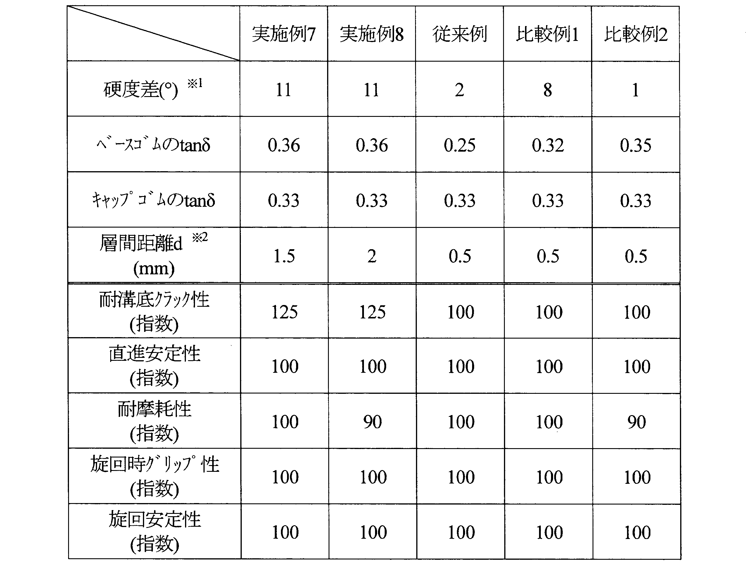
- Example 1 to 8 Conventional Example and Comparative Examples 1 and 2> A pneumatic tire for a motorcycle having the cross-sectional structure shown in FIG. 1 was produced with a tire size of 160 / 60ZR17M / C.
- the physical properties of the base rubber layer 4 and the cap rubber layer 5, and the distance between the groove bottom of the shoulder portion and the base rubber are as shown in Tables 1 and 2 below.
- the carcass 1 has two layers, nylon is used as the reinforcing cord, and the carcass 1 is disposed at 90 ° with respect to the tire circumferential direction.
- the belt layer 2 a monospiral belt formed by spirally winding a rubber-coated steel cord was used.
- the cap rubber gauge / tread gauge ratio of the shoulder portion was 30%.
- the boundary between the cap rubber layer and the base rubber layer on the tread surface was 25% of the tread edge from the tread center.
- the loss tangent tan ⁇ of the cap rubber layer and the base rubber layer was measured under the conditions of a temperature of 60 ° C., a frequency of 15 Hz, and a strain of 5% using a viscoelasticity measuring device manufactured by Rheometrics.
- the pneumatic tire for motorcycles of the present invention suppresses the occurrence of cracks at the groove bottom in the shoulder portion while achieving a well-balanced straight running stability, wear resistance, turning grip performance and turning stability. You can see that it is made.
Abstract
Description
前記トレッド部が、ベースゴム層の単層からなるセンター部と、ベースゴム層とキャップゴム層とが順に積層されたショルダー部とからなり、前記キャップゴム層のゴムが前記ベースゴム層のゴムより低硬度であり、かつ、前記ショルダー部の溝底におけるキャップゴム層の厚みが1.0mm以上であることを特徴とするものである。ここで硬度とは、25℃におけるショアA硬度を意味し、市販の硬度計を用いて計測することができる。
図1は、本発明の一好適実施形態に係る自動二輪車用空気入りタイヤの左半分断面図である。図示するように、本発明のタイヤは、一対のビード部11と、それに連なる一対のサイドウォール部12と、両サイドウォール部間に連なるトレッド部13とを備え、これら各部をビード部11相互間にわたり補強する少なくとも1層、図示例では2層のカーカスプライ1からなるカーカスと、そのタイヤ半径方向外側に配置され、補強コードが周方向に螺旋状に巻回されてなるベルト層2とを有している。また、トレッド部13には溝が設けられており、図中の破線は溝底3を示している。
<実施例1~8、従来例および比較例1、2>
図1に示す断面構造を有する自動二輪車用空気入りタイヤを、タイヤサイズ160/60ZR17M/Cにて作製した。ベースゴム層4およびキャップゴム層5の物性およびショルダー部の溝底とベースゴム間距離は下記表1および2に示すとおりである。カーカス1は2層とし、補強コードにはナイロンを用い、タイヤ周方向に対して90°となるように配置した。また、ベルト層2には、ゴム被覆スチールコードを螺旋状に巻回してなるモノスパイラルベルトを用いた。ショルダー部のキャップゴムゲージ/トレッドゲージ比は30%とした。キャップゴム層とベースゴム層のトレッド表面での境界はトレッドセンターからトレッド端の25%とした。得られたタイヤにつき、下記項目について試験を行い評価した。なお、キャップゴム層およびベースゴム層の損失正接tanδは、レオメトリックス社製の粘弾性測定装置を用いて、温度60℃、周波数15Hz、歪5%の条件で測定した。
各タイヤをMT4.50-17M/Cのリムに装着し、ドラム試験を行った。溝底にクラックが発生した走行距離を求め、指数表示した。この数値が大きいほど耐溝底クラック性は優れている。ドラム試験の条件は下記のとおりである。
内圧:290kPa
荷重:3.19kN
速度:50km/h
各タイヤを、標準リムに装着してタイヤ車輪とし、このタイヤ車輪二輪車の後輪に装着し、所定のテスト路で実車走行し、直進安定性、旋回時グリップ性および旋回安定性について、ドライバーによるフィーリング評価を行った。得られた結果を従来例を100とした指数にて評価した。この値が大きいほど、結果が優れていることを意味する。得られた結果を表1および2に示す。
上記実車テストを行う前に、タイヤの重量を測定しておき、実車走行後にタイヤに付着したゴムかすや小石などの付着物を綺麗に取り除いてタイヤの重量を測定し、新品時からの重量差を摩耗量として評価した。従来例のタイヤの摩耗重量を100として、各供試タイヤの摩耗量を指数で比較した。この値が小さいほど摩耗が少ないことを意味する。結果を表1および2に併記する。

※2:ショルダー部の溝底とベースゴム間距離
※2:ショルダー部の溝底とベースゴム間距離
2 ベルト層
3 溝底
4 ベースゴム層
5 キャップゴム層
11 ビード部
12 サイドウォール部
13 トレッド部
Claims (4)
- 環状に形成されたトレッド部を備える自動二輪車用空気入りタイヤにおいて、
前記トレッド部が、ベースゴム層の単層からなるセンター部と、ベースゴム層とキャップゴム層とが順に積層されたショルダー部とからなり、前記キャップゴム層のゴムが前記ベースゴム層のゴムより低硬度であり、かつ、前記ショルダー部の溝底におけるキャップゴム層の厚みが1.0mm以上であることを特徴とする自動二輪車用空気入りタイヤ。 - 前記キャップゴム層のゴムが前記ベースゴム層のゴムより2°以上6°未満低硬度である請求項1記載の自動二輪車用空気入りタイヤ。
- 前記キャップゴム層のゴムが前記ベースゴム層のゴムより6°以上低硬度であり、かつ、前記ショルダー部の溝底におけるキャップゴム層の厚みが1.5mm以上である請求項1記載の自動二輪車用空気入りタイヤ。
- 前記キャップゴム層のゴムの60℃における損失正接tanδが0.20~0.45であり、かつ前記ベースゴム層のゴムの60℃におけるtanδが0.05~0.36である請求項1記載の自動二輪車用空気入りタイヤ。
Priority Applications (4)
| Application Number | Priority Date | Filing Date | Title |
|---|---|---|---|
| CN2012800090878A CN103370210A (zh) | 2011-02-17 | 2012-02-16 | 机动两轮车用充气轮胎 |
| EP12747443.5A EP2676811A4 (en) | 2011-02-17 | 2012-02-16 | Pneumatic tire for motorcycle |
| US13/980,411 US20130299054A1 (en) | 2011-02-17 | 2012-02-16 | Pneumatic tire for motorcycle |
| JP2012558025A JPWO2012111776A1 (ja) | 2011-02-17 | 2012-02-16 | 自動二輪車用空気入りタイヤ |
Applications Claiming Priority (2)
| Application Number | Priority Date | Filing Date | Title |
|---|---|---|---|
| JP2011-031923 | 2011-02-17 | ||
| JP2011031923 | 2011-02-17 |
Publications (1)
| Publication Number | Publication Date |
|---|---|
| WO2012111776A1 true WO2012111776A1 (ja) | 2012-08-23 |
Family
ID=46672688
Family Applications (1)
| Application Number | Title | Priority Date | Filing Date |
|---|---|---|---|
| PCT/JP2012/053721 WO2012111776A1 (ja) | 2011-02-17 | 2012-02-16 | 自動二輪車用空気入りタイヤ |
Country Status (5)
| Country | Link |
|---|---|
| US (1) | US20130299054A1 (ja) |
| EP (1) | EP2676811A4 (ja) |
| JP (1) | JPWO2012111776A1 (ja) |
| CN (1) | CN103370210A (ja) |
| WO (1) | WO2012111776A1 (ja) |
Cited By (3)
| Publication number | Priority date | Publication date | Assignee | Title |
|---|---|---|---|---|
| JP2014162367A (ja) * | 2013-02-26 | 2014-09-08 | Sumitomo Rubber Ind Ltd | 自動二輪車用タイヤ |
| JP2018076002A (ja) * | 2016-11-10 | 2018-05-17 | 住友ゴム工業株式会社 | 自動二輪車用空気入りタイヤ |
| WO2019012965A1 (ja) * | 2017-07-14 | 2019-01-17 | 株式会社ブリヂストン | 自動二輪車用空気入りタイヤ |
Families Citing this family (4)
| Publication number | Priority date | Publication date | Assignee | Title |
|---|---|---|---|---|
| BR112016013730B1 (pt) * | 2013-12-23 | 2021-04-13 | Pirelli Tyre S.P.A. | Pneu para motocicletas |
| JP6253147B2 (ja) * | 2014-03-17 | 2017-12-27 | 住友ゴム工業株式会社 | 空気入りタイヤ |
| FR3062343A1 (fr) * | 2017-01-27 | 2018-08-03 | Compagnie Generale Des Etablissements Michelin | Pneumatique a bande de roulement optimisee |
| JP7000886B2 (ja) | 2018-02-01 | 2022-01-19 | 住友ゴム工業株式会社 | 自動二輪車用タイヤ |
Citations (4)
| Publication number | Priority date | Publication date | Assignee | Title |
|---|---|---|---|---|
| JPS6094804A (ja) | 1983-10-31 | 1985-05-28 | Yokohama Rubber Co Ltd:The | 二輪自動車用タイヤ |
| JPH11189010A (ja) | 1997-12-25 | 1999-07-13 | Bridgestone Corp | 二輪自動車用空気入りタイヤ |
| JP2005271760A (ja) | 2004-03-25 | 2005-10-06 | Sumitomo Rubber Ind Ltd | 自動二輪車用タイヤ |
| JP2007223569A (ja) * | 2006-02-27 | 2007-09-06 | Bridgestone Corp | 自動二輪車用空気入りラジアルタイヤ |
Family Cites Families (7)
| Publication number | Priority date | Publication date | Assignee | Title |
|---|---|---|---|---|
| JP3391568B2 (ja) * | 1994-07-29 | 2003-03-31 | 住友ゴム工業株式会社 | 自動二輪車用ラジアルタイヤ |
| JP4350622B2 (ja) * | 2004-09-07 | 2009-10-21 | 住友ゴム工業株式会社 | 空気入りタイヤ |
| JP4630096B2 (ja) * | 2005-03-15 | 2011-02-09 | 住友ゴム工業株式会社 | 自動二輪車用タイヤ |
| JP2007283803A (ja) * | 2006-04-12 | 2007-11-01 | Bridgestone Corp | 二輪車用空気入りタイヤ |
| JP5160835B2 (ja) * | 2007-08-08 | 2013-03-13 | 株式会社ブリヂストン | 更生タイヤ用プレキュアトレッド及び更生タイヤ |
| JP5179802B2 (ja) * | 2007-08-24 | 2013-04-10 | 株式会社ブリヂストン | 二輪車用タイヤ |
| EP2307207B1 (en) * | 2008-06-20 | 2012-02-08 | Pirelli Tyre S.P.A. | Motorcycle tyre |
-
2012
- 2012-02-16 EP EP12747443.5A patent/EP2676811A4/en not_active Withdrawn
- 2012-02-16 US US13/980,411 patent/US20130299054A1/en not_active Abandoned
- 2012-02-16 JP JP2012558025A patent/JPWO2012111776A1/ja active Pending
- 2012-02-16 WO PCT/JP2012/053721 patent/WO2012111776A1/ja active Application Filing
- 2012-02-16 CN CN2012800090878A patent/CN103370210A/zh active Pending
Patent Citations (4)
| Publication number | Priority date | Publication date | Assignee | Title |
|---|---|---|---|---|
| JPS6094804A (ja) | 1983-10-31 | 1985-05-28 | Yokohama Rubber Co Ltd:The | 二輪自動車用タイヤ |
| JPH11189010A (ja) | 1997-12-25 | 1999-07-13 | Bridgestone Corp | 二輪自動車用空気入りタイヤ |
| JP2005271760A (ja) | 2004-03-25 | 2005-10-06 | Sumitomo Rubber Ind Ltd | 自動二輪車用タイヤ |
| JP2007223569A (ja) * | 2006-02-27 | 2007-09-06 | Bridgestone Corp | 自動二輪車用空気入りラジアルタイヤ |
Non-Patent Citations (1)
| Title |
|---|
| See also references of EP2676811A4 |
Cited By (5)
| Publication number | Priority date | Publication date | Assignee | Title |
|---|---|---|---|---|
| JP2014162367A (ja) * | 2013-02-26 | 2014-09-08 | Sumitomo Rubber Ind Ltd | 自動二輪車用タイヤ |
| JP2018076002A (ja) * | 2016-11-10 | 2018-05-17 | 住友ゴム工業株式会社 | 自動二輪車用空気入りタイヤ |
| WO2019012965A1 (ja) * | 2017-07-14 | 2019-01-17 | 株式会社ブリヂストン | 自動二輪車用空気入りタイヤ |
| JP2019018675A (ja) * | 2017-07-14 | 2019-02-07 | 株式会社ブリヂストン | 自動二輪車用空気入りタイヤ |
| US11787236B2 (en) | 2017-07-14 | 2023-10-17 | Bridgestone Corporation | Pneumatic tire for motorcycle |
Also Published As
| Publication number | Publication date |
|---|---|
| US20130299054A1 (en) | 2013-11-14 |
| EP2676811A4 (en) | 2017-01-11 |
| CN103370210A (zh) | 2013-10-23 |
| JPWO2012111776A1 (ja) | 2014-07-07 |
| EP2676811A1 (en) | 2013-12-25 |
Similar Documents
| Publication | Publication Date | Title |
|---|---|---|
| WO2012111776A1 (ja) | 自動二輪車用空気入りタイヤ | |
| JP5756486B2 (ja) | 空気入りタイヤ | |
| JP5007740B2 (ja) | 空気入りタイヤ | |
| JP4744392B2 (ja) | 自動二輪車用空気入りラジアルタイヤ | |
| US9290063B2 (en) | Motorcycle tire for uneven terrain | |
| JP6320764B2 (ja) | 自動二輪車用タイヤ | |
| JP5353275B2 (ja) | 空気入りラジアルタイヤ | |
| JP2015157547A (ja) | 空気入りタイヤ | |
| JP2010221820A (ja) | 空気入りタイヤ | |
| JP5868040B2 (ja) | 二輪自動車用タイヤ | |
| JP2008222155A (ja) | 二輪車用空気入りタイヤ | |
| JP5788217B2 (ja) | 自動二輪車用空気入りタイヤ | |
| JP7081207B2 (ja) | 二輪車用タイヤ | |
| JP2012140068A (ja) | 空気入りタイヤ | |
| JP6523138B2 (ja) | 自動二輪車用空気入りラジアルタイヤ | |
| JP4842047B2 (ja) | 自動二輪車用空気入りラジアルタイヤ | |
| JP6013938B2 (ja) | 自動二輪車用タイヤ | |
| WO2019012965A1 (ja) | 自動二輪車用空気入りタイヤ | |
| JP6141178B2 (ja) | 空気入りタイヤ | |
| JP6192491B2 (ja) | 空気入りタイヤ | |
| JP5680906B2 (ja) | 自動二輪車用空気入りタイヤ | |
| JP7056227B2 (ja) | 二輪車用タイヤ | |
| JP6030946B2 (ja) | 空気入りタイヤ | |
| JP6457758B2 (ja) | 二輪自動車用タイヤ | |
| JP5980581B2 (ja) | 空気入りタイヤ |
Legal Events
| Date | Code | Title | Description |
|---|---|---|---|
| 121 | Ep: the epo has been informed by wipo that ep was designated in this application |
Ref document number: 12747443 Country of ref document: EP Kind code of ref document: A1 |
|
| ENP | Entry into the national phase |
Ref document number: 2012558025 Country of ref document: JP Kind code of ref document: A |
|
| WWE | Wipo information: entry into national phase |
Ref document number: 13980411 Country of ref document: US Ref document number: 2012747443 Country of ref document: EP |
|
| NENP | Non-entry into the national phase |
Ref country code: DE |