WO2012108391A1 - ガラス板の切断方法及びガラス板の切断装置 - Google Patents
ガラス板の切断方法及びガラス板の切断装置 Download PDFInfo
- Publication number
- WO2012108391A1 WO2012108391A1 PCT/JP2012/052644 JP2012052644W WO2012108391A1 WO 2012108391 A1 WO2012108391 A1 WO 2012108391A1 JP 2012052644 W JP2012052644 W JP 2012052644W WO 2012108391 A1 WO2012108391 A1 WO 2012108391A1
- Authority
- WO
- WIPO (PCT)
- Prior art keywords
- glass plate
- cutting
- cut line
- cut
- line
- Prior art date
- Legal status (The legal status is an assumption and is not a legal conclusion. Google has not performed a legal analysis and makes no representation as to the accuracy of the status listed.)
- Ceased
Links
Images






Classifications
-
- C—CHEMISTRY; METALLURGY
- C03—GLASS; MINERAL OR SLAG WOOL
- C03B—MANUFACTURE, SHAPING, OR SUPPLEMENTARY PROCESSES
- C03B33/00—Severing cooled glass
- C03B33/02—Cutting or splitting sheet glass or ribbons; Apparatus or machines therefor
-
- C—CHEMISTRY; METALLURGY
- C03—GLASS; MINERAL OR SLAG WOOL
- C03B—MANUFACTURE, SHAPING, OR SUPPLEMENTARY PROCESSES
- C03B33/00—Severing cooled glass
- C03B33/02—Cutting or splitting sheet glass or ribbons; Apparatus or machines therefor
- C03B33/023—Cutting or splitting sheet glass or ribbons; Apparatus or machines therefor the sheet or ribbon being in a horizontal position
- C03B33/033—Apparatus for opening score lines in glass sheets
-
- B—PERFORMING OPERATIONS; TRANSPORTING
- B28—WORKING CEMENT, CLAY, OR STONE
- B28D—WORKING STONE OR STONE-LIKE MATERIALS
- B28D5/00—Fine working of gems, jewels, crystals, e.g. of semiconductor material; apparatus or devices therefor
-
- B—PERFORMING OPERATIONS; TRANSPORTING
- B65—CONVEYING; PACKING; STORING; HANDLING THIN OR FILAMENTARY MATERIAL
- B65G—TRANSPORT OR STORAGE DEVICES, e.g. CONVEYORS FOR LOADING OR TIPPING, SHOP CONVEYOR SYSTEMS OR PNEUMATIC TUBE CONVEYORS
- B65G2249/00—Aspects relating to conveying systems for the manufacture of fragile sheets
- B65G2249/04—Arrangements of vacuum systems or suction cups
Definitions
- the present invention relates to a glass plate cutting method and a glass plate cutting device.
- Patent Document 1 discloses a cutting device that cuts a glass plate whose cut line has been processed by a cutter along the cut line.
- the cutting device of Patent Document 1 includes a first clamping member including a pressing portion and a receiving portion on the upstream side in the conveyance direction of the glass plate, and includes a pressing portion and a receiving portion on the downstream side in the conveyance direction of the glass plate.
- a second clamping member is provided.
- the glass surface on the upstream side with respect to the cutting line is clamped by the first clamping member, and the glass surface on the downstream side with respect to the cutting line is clamped by the second clamping member.
- the second holding member on the downstream side is rotated around an axis installed at a position below the cutting line. By this operation, the glass plates are cut along the cutting line, and the cut surfaces of the cut glass plates are separated from each other.
- This invention is made
- the present invention provides a glass plate cutting method for cutting a cut glass sheet along the cut line, the width of one glass plate facing each other across the cut line of the glass plate.
- the lower surface and the upper surface in the direction are held by a pair of holding members, and the lower surface in the width direction of the other glass plate facing each other across the cutting line of the glass plate is supported by the support member, and the folding member has a predetermined gap with respect to the upper surface
- the cutting member made of the support member and the folding member is rotated about the lower position of the cutting line by the rotation drive unit as the rotation center, so that the lowermost edge part of the folding member is farthest from the cutting line.
- the edge portion pressed against the upper surface of the other glass plate, the glass plate is folded along the cut line, and the cut glass It provides a method for cutting a glass plate separating the cut faces of the scan plate.
- the present invention provides a glass plate cutting device for cutting a cut glass sheet along the cut line, wherein one of the glass plates facing each other across the cut line of the glass plate.
- a pair of holding members that hold the lower surface and the upper surface in the width direction, a support member that supports the lower surface in the width direction of the other glass plate facing each other across the cut line of the glass plate, and a predetermined gap with respect to the upper surface
- a glass plate cutting apparatus comprising: a cutting member having a folded member; and a rotation driving unit that rotates the cutting member about a position below the cutting line as a rotation center.
- the folding member since the gap is provided between the folding member and the glass plate, when the folding member rotates during the cutting of the glass plate, the folding member has an edge portion that is farthest from the cut line at the glass portion. Abuts the plate first. As the folding member rotates, the folding member is pressed against the glass plate while gradually increasing the area in contact with the glass plate from the edge portion toward the edge portion closest to the cut line. The glass plate is cut along the cutting line by the operation of this folding member, but at the time of cutting, the cutting line is not subjected to excessive force from the folding member, so that the cut surface of the glass plate is not cracked, and thus the cutting is performed. The surface is good.
- the cut surfaces of the glass plates are separated from each other when the glass plates are cut, so that contact between the cut surfaces can be prevented and a good cut surface can be obtained.
- the cut glass plate passes between the support member and the folded member by its own weight and falls.
- the present invention provides a glass plate cutting method for cutting a cut glass sheet along the cut line, the width of one glass plate facing each other across the cut line of the glass plate
- the lower surface and the upper surface in the direction are held by a pair of holding members, and the lower surface in the width direction of the other glass plate facing each other across the cutting line of the glass plate is supported by the support member, and the folding member has a predetermined gap with respect to the upper surface
- the glass plate is generated in the tangent line by arranging the folding member as a long member in parallel with the tangent line and inclining the lower surface of the foldable member with respect to the upper surface of the other glass plate.
- the folding start point is one place, the folding member is moved downward toward the glass plate, and the glass plate is moved from one end in the tangential direction by the folding member.
- the glass plate is folded along the cut line, and the cutting member composed of the support member and the folding member is rotated at a position below the cut line by a rotation drive unit.
- the cutting method of the glass plate which separates the cut surfaces of the cut glass plate is provided.
- the present invention provides a glass plate cutting device for cutting a cut glass sheet along the cut line, wherein one of the glass plates facing each other across the cut line of the glass plate.
- a pair of holding members that hold the lower surface and the upper surface in the width direction, a support member that supports the lower surface in the width direction of the other glass plate facing each other across the cut line of the glass plate, and a predetermined gap with respect to the upper surface
- a cutting member having a folding member, a vertical movement drive unit that moves the folding member up and down with respect to the upper surface of the other glass plate, and a rotation drive unit that rotates the cutting member around a position below the cutting line.
- the folding member is disposed as a long member parallel to the cutting line, and cuts the glass plate that inclines the lower surface of the folding member with respect to the upper surface of the other glass plate.
- the glass plate when the folding member is moved downward toward the glass plate, the glass plate is gradually pressed from the one end portion of the glass plate to the other end portion by the folding member, and the contact between the folding member and the glass plate is achieved.
- the cut line is cracked from one end to the other end. For this reason, since a plurality of cracks do not occur at the same time in the cut line, it is possible to reliably prevent cracking.
- the support member is lowered by the downward movement of the folding member by the vertical movement drive unit and the rotation operation by the rotation drive unit. Along with this, a gap is formed between the cut glass plate and the support member, so that the cut glass plate passes between the support member and the folding member by its own weight and falls.
- the glass plate can be gradually pressed from one end portion to the other end portion by the folding member, the cut line is cracked from the one end portion toward the other end portion. For this reason, since a plurality of cracks do not occur at the same time in the cut line, it is possible to reliably prevent cracking.
- the cut surface of the glass plate is not chipped, so that a good cut surface can be obtained.
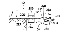
- FIG. 1 is a main part configuration diagram of a glass sheet cutting device according to a first embodiment.
- FIG. 2 is an operation explanatory diagram of the cutting apparatus shown in FIG.
- FIG. 3 is an explanatory view showing another form of the support member and the folding member.
- FIG. 4 is an operation explanatory diagram of the cutting device shown in FIG.
- FIG. 5 is an operation explanatory diagram of the cutting apparatus shown in FIG.
- FIG. 6 is an operation explanatory diagram of the cutting apparatus shown in FIG.
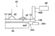
- FIG. 7 is a side view of an essential part of the glass sheet cutting device according to the second embodiment.
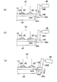
- 8 (a) to 8 (c) are operation explanatory views of the cutting device shown in FIG. 9 (a) to 9 (c) are operation explanatory views of the glass sheet cutting device according to the third embodiment.
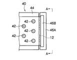
- FIG. 10 is a plan view of the cutting device shown in FIG.
- FIG. 11 is an arrow view of the cutting device shown in FIG. 10 as seen from the line AA.
- FIG. 12 is an overall perspective view showing an example of a cutting device.
- FIG. 13 is an overall perspective view showing an example of a cutting device.
- FIG. 1 is a side view of an essential part of a glass sheet cutting device 10 according to a first embodiment.
- a cutting apparatus 10 shown in FIG. 1 includes a table 16 on which a glass plate 14 with a cut line 12 is processed.
- the glass plate 14 is arranged so that the cut line 12 is positioned outward from an edge 18 of the table 16. Placed on.
- the cutting device 10 includes a pair of holding members 20A and 20B that hold the lower surface and the upper surface in the width direction of one glass plate 14A facing each other across the cutting line 12 of the glass plate 14. These holding members 20A and 20B are arranged to face each other in the vertical direction.
- Rubber, resin, or plastic dampers 22A and 22B are attached to the glass contact surfaces of the holding members 20A and 20B, respectively. As shown in FIG. 2, the damper 22A does not touch the lower surface of the glass plate 14A without a gap. The damper 22B is in contact with the upper surface of the glass plate 14A without any gap.
- the holding member 20A is fixed in advance to a position where it abuts on the lower surface of the glass plate 14A, and the holding member 20B is attached to the upper surface of the glass plate 14A so as to be movable forward and backward. It is moved up and down by the vertical movement drive unit 24 shown in FIG.
- the cutting device 10 includes a support member 26A that supports the lower surface in the width direction of the other glass plate 14B facing each other across the cutting line 12 of the glass plate 14. Moreover, the folding member 26B arrange
- Rubber, resin, or plastic dampers 30A and 30B are attached to the glass contact surfaces of the support member 26A and the folding member 26B, and the damper 30A is attached to the lower surface of the glass plate 14B as shown in FIG.
- the damper 30B is abutted with no gap, and the damper 30B is disposed apart from the upper surface of the glass plate 14B with the gap 28.
- the folding member 26B is attached to the upper surface of the glass plate 14B so as to be movable back and forth in the vertical direction, and is moved up and down by the vertical movement drive unit 32 shown in FIG. Further, the support member 26A and the folding member 26B constitute a cutting member that cuts the glass plate 14B along the cutting line 12 with respect to the glass plate 14A, and the shaft 34 set at a position below the cutting line 12 is the center. It is configured to be freely rotatable, and is integrally rotated by a rotation driving unit 36 shown in FIG.
- the operations of the vertical movement drive unit 24, the vertical movement drive unit 32, and the rotation drive unit 36 described above are controlled by a CPU 38 that controls the entire apparatus.
- the glass contact surfaces of the dampers 30A and 30B are flat and parallel to the surface of the glass plate 14B, but the present invention is not limited to this.
- the dampers 31 ⁇ / b> A and 31 ⁇ / b> B may be inclined surfaces inclined downward to the right.
- the glass plate 14A cut along the cutting line 12 is handled as a glass plate of the product, and thereafter, the process proceeds to a chamfering process.
- the cut glass plate 14 ⁇ / b> B is a so-called ear glass piece, which is crushed and reused after cutting.
- the holding member 20B is moved downward by the vertical movement drive unit 24 from the initial position shown in FIG. 1, and the lower surface and the upper surface in the width direction of the glass plate 14A are moved by the pair of holding members 20A and 20B as shown in FIG. Hold.
- the folding member 26B is moved downward from the initial position shown in FIG. 1 by the vertical movement drive unit 32, and the folding member 26B is arranged with a predetermined gap 28 as shown in FIG. 2 with respect to the upper surface of the glass plate 14B. . That is, the position in FIG. 2 is a position immediately before the start of cutting the glass plate 14.
- the glass plate 14B is cut along the cutting line 12 by the rotation of the folding member 26B, but the cutting line 12 is not subjected to excessive force from the folding member 26B by the above-described contact area increasing operation of the folding member 26B.
- the cut surfaces of each of the plate 14A and the glass plate 14 are not chipped, so that the cut surfaces are good.
- the cut glass plate 14B since the gap 28 shown in FIG. 2 originally exists between the cut glass plate 14B and the folding member 26B, the cut glass plate 14B has its own weight between the support member 26A and the folding member 26B. It slips through and falls. Therefore, in order to drop the cut glass plate 14B, the operation of widening the interval between the support member 26A and the folding member 26B can be omitted.
- FIG. 7 is a side view of an essential part of the glass sheet cutting device 40 according to the second embodiment, and FIGS. 8A to 8C are operation explanatory views of the cutting device shown in FIG. is there. *
- the glass plate 14 to be cut is held by suction on the upper surface of the glass plate 14A by a plurality of suction pads 42, 42...
- the lower surface of the glass plate 14 ⁇ / b> A is pressed against the table 44 by the pads 42, 42. Therefore, the glass plate 14 ⁇ / b> B is disposed outward from the edge 44 ⁇ / b> A of the table 44.
- the suction pads 42, 42... And the table 44 constitute a pair of holding members.
- a supporting member 46A is disposed below the glass plate 14B, and a folding member 46B is disposed above.
- the folding member 46B is installed so as to be movable up and down, and is moved up and down by a vertical movement drive unit 48.
- a glass plate cutting method by the glass plate cutting device 40 according to the second embodiment configured as shown in FIG. 7 will be described.
- the folding member 46B is moved downward by the vertical movement drive unit 48, and the folding member 46B is arranged with a predetermined gap 28 on the upper surface of the glass plate 14B. That is, the position in FIG. 8A is the position immediately before the start of cutting the glass plate 14.
- the cutting member composed of the support member 46A and the folding member 46B is rotated clockwise as shown in FIG. 8B around the shaft 34A set at the lower position of the cutting line 12 by a rotation drive unit (not shown). Rotate.
- the folding member 46B rotates, the folding member 46B is pressed against the upper surface of the glass plate 14B while gradually increasing the area in contact with the glass plate 14B as shown in FIGS. 8 (b) and 8 (c). To go.
- the glass plate 14B is cut along the cutting line 12 by the rotation operation of the folding member 46B.
- the cutting line 12 is not subjected to excessive force from the folding member 46B by the above-described contact area increasing operation of the folding member 46B.
- the cut surfaces of each of the plate 14A and the glass plate 14 are not chipped, so that the cut surfaces are good.
- the cut surfaces of the glass plate 14A and the glass plate 14B are separated from each other, so that contact between the cut surfaces can be prevented and a good cut surface can be obtained.
- the cut glass plate 14B is separated from the support member 46A and the folding member 46B. It falls through its own weight and falls. Therefore, in order to drop the cut glass plate 14B, the operation of widening the gap between the support member 46A and the folding member 46B can be omitted.
- FIG. 9 (a) to 9 (c) are operation explanatory views of the glass sheet cutting device 40 according to the third embodiment
- FIG. 10 is a plan view of the cutting device shown in FIG. 9 (a). It is.
- FIG. 11 is an arrow view of the cutting device 40 shown in FIG. 10 viewed from the line AA.
- the structure of the glass plate cutting device 40 according to the third embodiment is the same as that of the glass plate cutting device 40 according to the second embodiment except for the configuration of the folding member 46B. Description is omitted.
- the support member 46 ⁇ / b> A is also installed so as to be movable up and down, and is moved up and down by the vertical movement drive unit 48.
- the folding member 46B is a long member, and is arranged in parallel with the cutting line 12.
- the lower surface of the folding member 46B is inclined with respect to the upper surface of the glass plate 14B as shown in FIG. Thereby, when the folding member 46B comes into contact with the upper surface of the glass plate 14B, the folding start point of the glass plate 14B generated at the severing line 12 can be made one place.
- the glass plate cutting method by the glass plate cutting device 40 according to the third embodiment will be described.
- the folding member 46B is moved downward by the vertical movement drive unit 48, and the folding member 46B is arranged with a predetermined gap 28 on the upper surface of the glass plate 14B. That is, the position in FIG. 9A is the position immediately before the start of cutting the glass plate 14.
- the glass plate 14B is gradually moved from the one end a to the other end b as shown in FIG. 11 by the folding member 46B.
- the area where the folding member 46B and the glass plate 14B come into contact with each other gradually increases.
- the cut line 12 is cracked from one end a toward the other end b. For this reason, since a plurality of cracks do not occur at the same time in the cut line, it is possible to reliably prevent cracking.
- the glass plate 14B is sandwiched between cutting members made of the supporting member 46A and the folding member 46B.
- the cutting member is rotated clockwise around a shaft 34A set at a position below the cutting line 12 by a rotation driving unit (not shown) as shown in FIG. Is folded along the cutting line 12.
- the support member 46A is lowered in the direction of the arrow shown in FIG. 9C by the downward movement of the support member 46A by the vertical movement drive unit 48 and the rotation operation by the rotation drive unit (not shown).
- a gap is formed between the cut glass plate 14B and the support member 46A as shown in FIG. 9C, so that the cut glass plate 14B has its own weight between the support member 46A and the folding member 46B. It slips through and falls.
- FIGS. 12 and 13 are overall perspective views showing an example of the cutting device 10 shown in FIGS. 1 to 6.
- FIG. 12 and 13 are overall perspective views showing an example of the cutting device 10 shown in FIGS. 1 to 6.
- FIG. 12 and 13 are overall perspective views showing an example of the cutting device 10 shown in FIGS. 1 to 6.
- the glass plate 14 to be cut is sucked and held by suction pads 52, 52...
- the glass plate 14 is pressed and fixed to the table 16 by the downward movement of the transfer machine 50, and in this state, the glass plate 14B is cut from the glass plate 14A by the cutting device 10 shown in FIGS.
- the cut glass plate 14A is sucked and held by the suction pads 56, 56... Of the carry-out transfer machine 54 and is transported from the table 16 to a chamfering device (not shown).
Landscapes
- Chemical & Material Sciences (AREA)
- Engineering & Computer Science (AREA)
- Materials Engineering (AREA)
- Organic Chemistry (AREA)
- Mechanical Engineering (AREA)
- Re-Forming, After-Treatment, Cutting And Transporting Of Glass Products (AREA)
- Processing Of Stones Or Stones Resemblance Materials (AREA)
Abstract
Description
本出願は、2011年2月9日出願の日本特許出願2011-026200に基づくものであり、その内容はここに参照として取り込まれる。
Claims (4)
- 切線が加工されたガラス板を前記切線に沿って切断するガラス板の切断方法において、
前記ガラス板の切線を挟んで対峙する一方のガラス板の幅方向における下面及び上面を一対の保持部材によって保持し、
前記ガラス板の切線を挟んで対峙する他方のガラス板の幅方向における下面を支持部材によって支持するとともに、上面に対し所定の隙間をもって折り部材を配置し、
前記支持部材及び前記折り部材からなる切断部材を、回転駆動部によって前記切線の下方位置を回転中心として回転させることにより、前記折り部材の下面エッジ部のうち、前記切線から最も離れたエッジ部を前記他方のガラス板の上面に押圧当接させて、前記ガラス板を前記切線に沿って折り割りするとともに切断されたガラス板の切断面同士を引き離すガラス板の切断方法。 - 切線が加工されたガラス板を前記切線に沿って切断するガラス板の切断方法において、
前記ガラス板の切線を挟んで対峙する一方のガラス板の幅方向における下面及び上面を一対の保持部材によって保持し、
前記ガラス板の切線を挟んで対峙する他方のガラス板の幅方向における下面を支持部材によって支持するとともに、上面に対し所定の隙間をもって折り部材を配置し、
前記折り部材を長尺状部材として、前記切線と平行に配置し、前記折り部材の下面を前記他方のガラス板の上面に対し傾斜させることにより、前記切線に発生する前記ガラス板の折り割り開始点を一箇所とし、
前記折り部材を前記ガラス板に向けて下降移動させて、前記ガラス板を前記折り部材によって切線方向の一端部から他端部に向けて徐々に押圧することにより、前記ガラス板を前記切線に沿って折り割りするとともに、
前記支持部材及び前記折り部材からなる切断部材を、回転駆動部によって前記切線の下方位置を回転中心として回転させることにより、切断されたガラス板の切断面同士を引き離すガラス板の切断方法。 - 切線が加工されたガラス板を前記切線に沿って切断するガラス板の切断装置において、
前記ガラス板の切線を挟んで対峙する一方のガラス板の幅方向における下面及び上面を保持する一対の保持部材と、
前記ガラス板の切線を挟んで対峙する他方のガラス板の幅方向における下面を支持する支持部材、及び上面に対し所定の隙間をもって配置された折り部材を有する切断部材と、
前記切断部材を前記切線の下方位置を回転中心として回転させる回転駆動部と、
を備えたガラス板の切断装置。 - 切線が加工されたガラス板を前記切線に沿って切断するガラス板の切断装置において、
前記ガラス板の切線を挟んで対峙する一方のガラス板の幅方向における下面及び上面を保持する一対の保持部材と、
前記ガラス板の切線を挟んで対峙する他方のガラス板の幅方向における下面を支持する支持部材、及び上面に対し所定の隙間をもって配置された折り部材を有する切断部材と、
前記折り部材を前記他方のガラス板の上面に対して上下移動させる上下動駆動部と、
前記切断部材を前記切線の下方位置を回転中心として回転させる回転駆動部と、
を備え
前記折り部材は長尺状部材として、前記切線と平行に配置され、前記折り部材の下面を前記他方のガラス板の上面に対し傾斜させるガラス板の切断装置。
Priority Applications (3)
| Application Number | Priority Date | Filing Date | Title |
|---|---|---|---|
| JP2012556882A JP5935698B2 (ja) | 2011-02-09 | 2012-02-06 | ガラス板の切断方法及びガラス板の切断装置 |
| KR1020137021049A KR101832020B1 (ko) | 2011-02-09 | 2012-02-06 | 유리판의 절단 방법 및 유리판의 절단 장치 |
| CN201280008456.1A CN103347828B (zh) | 2011-02-09 | 2012-02-06 | 玻璃板的切断方法及玻璃板的切断装置 |
Applications Claiming Priority (2)
| Application Number | Priority Date | Filing Date | Title |
|---|---|---|---|
| JP2011026200 | 2011-02-09 | ||
| JP2011-026200 | 2011-02-09 |
Publications (1)
| Publication Number | Publication Date |
|---|---|
| WO2012108391A1 true WO2012108391A1 (ja) | 2012-08-16 |
Family
ID=46638606
Family Applications (1)
| Application Number | Title | Priority Date | Filing Date |
|---|---|---|---|
| PCT/JP2012/052644 Ceased WO2012108391A1 (ja) | 2011-02-09 | 2012-02-06 | ガラス板の切断方法及びガラス板の切断装置 |
Country Status (5)
| Country | Link |
|---|---|
| JP (1) | JP5935698B2 (ja) |
| KR (1) | KR101832020B1 (ja) |
| CN (1) | CN103347828B (ja) |
| TW (1) | TWI525053B (ja) |
| WO (1) | WO2012108391A1 (ja) |
Cited By (8)
| Publication number | Priority date | Publication date | Assignee | Title |
|---|---|---|---|---|
| JP2014528892A (ja) * | 2011-08-12 | 2014-10-30 | コーニング インコーポレイテッド | ガラスシートの周縁領域を切除するための方法及び装置 |
| JP2015502907A (ja) * | 2011-11-30 | 2015-01-29 | コーニング インコーポレイテッド | ガラスシートの周縁部分を除去するための方法及び装置 |
| JP2015044722A (ja) * | 2013-08-29 | 2015-03-12 | 三星ダイヤモンド工業株式会社 | 分断機構 |
| WO2015098598A1 (ja) * | 2013-12-27 | 2015-07-02 | 旭硝子株式会社 | 脆性板の加工方法、および脆性板の加工装置 |
| KR20170039143A (ko) | 2014-08-04 | 2017-04-10 | 아사히 가라스 가부시키가이샤 | 무알칼리 유리판의 절단 방법, 디스플레이 패널의 절단 방법, 무알칼리 유리판의 제조 방법, 및 디스플레이 패널의 제조 방법 |
| CN110682450A (zh) * | 2019-10-17 | 2020-01-14 | 黄沄沄 | 一种玻璃加工装置及加工方法 |
| JP2021523086A (ja) * | 2018-05-14 | 2021-09-02 | コーニング インコーポレイテッド | ガラスシートを処理するための装置及び方法 |
| WO2023195189A1 (ja) * | 2022-04-08 | 2023-10-12 | 坂東機工株式会社 | 折割システム及び折割加工方法 |
Families Citing this family (11)
| Publication number | Priority date | Publication date | Assignee | Title |
|---|---|---|---|---|
| JP3160767B2 (ja) | 1991-05-01 | 2001-04-25 | 武内プレス工業株式会社 | 密封容器の製造方法 |
| KR101495872B1 (ko) * | 2014-12-01 | 2015-02-26 | 주식회사 삼일지앤드엠 | 판유리 절단장치 |
| JP6716900B2 (ja) * | 2015-12-04 | 2020-07-01 | 三星ダイヤモンド工業株式会社 | 分断装置 |
| CN105837021B (zh) * | 2016-05-27 | 2019-09-06 | 杨聪 | 条形光学玻璃逐步裂解装置 |
| FR3066488B1 (fr) * | 2017-05-19 | 2022-03-04 | Saint Gobain | Procede de rompage d'une feuille de verre |
| TWI753183B (zh) | 2017-07-12 | 2022-01-21 | 美商康寧公司 | 製造玻璃基板的設備及方法 |
| CN108503209B (zh) * | 2018-07-03 | 2020-12-01 | 常州大学 | 一种玻璃快速折断机 |
| CN109093857B (zh) * | 2018-07-03 | 2020-05-26 | 常州大学 | 基于双面应力集中的切割机 |
| CN110590147B (zh) * | 2019-09-18 | 2022-08-02 | 彩虹(合肥)液晶玻璃有限公司 | 分离方法、装置、设备和切割设备 |
| JP7098173B2 (ja) * | 2020-02-12 | 2022-07-11 | 三星ダイヤモンド工業株式会社 | 脆性材料基板の分断機構 |
| CN117428943B (zh) * | 2023-12-19 | 2024-03-01 | 南京中江新材料科技有限公司 | 一种dbc陶瓷基板的成型铣切装置及成型铣方法 |
Citations (5)
| Publication number | Priority date | Publication date | Assignee | Title |
|---|---|---|---|---|
| JPH02155610A (ja) * | 1988-12-07 | 1990-06-14 | Matsushita Electric Ind Co Ltd | 基板分割装置 |
| JPH04240130A (ja) * | 1991-01-16 | 1992-08-27 | Asahi Glass Co Ltd | 板硝子の切断方法及びその装置 |
| JPH0545033U (ja) * | 1991-11-07 | 1993-06-18 | 鐘淵化学工業株式会社 | ガラス基板の折割り治具 |
| JP2006321695A (ja) * | 2005-05-20 | 2006-11-30 | Central Glass Co Ltd | 板ガラスの折割装置 |
| JP2009227550A (ja) * | 2008-03-25 | 2009-10-08 | Nippon Electric Glass Co Ltd | ガラス板折割方法及びガラス板折割装置 |
Family Cites Families (4)
| Publication number | Priority date | Publication date | Assignee | Title |
|---|---|---|---|---|
| JP3031384B2 (ja) * | 1991-03-08 | 2000-04-10 | 旭硝子株式会社 | 硝子板の切断方法及びその装置 |
| JPH0674153B2 (ja) * | 1991-11-07 | 1994-09-21 | 旭硝子株式会社 | ガラス板の切断方法及びその装置 |
| US7131562B2 (en) * | 2001-01-17 | 2006-11-07 | Mitsuboshi Diamond Industrial Co., Ltd. | Scribing and breaking apparatus, system therefor, and scribing and breaking method |
| JP2006137170A (ja) * | 2004-11-12 | 2006-06-01 | Lemi Ltd | 脆性材料の割断方法及び装置 |
-
2012
- 2012-02-06 JP JP2012556882A patent/JP5935698B2/ja active Active
- 2012-02-06 KR KR1020137021049A patent/KR101832020B1/ko active Active
- 2012-02-06 CN CN201280008456.1A patent/CN103347828B/zh active Active
- 2012-02-06 WO PCT/JP2012/052644 patent/WO2012108391A1/ja not_active Ceased
- 2012-02-09 TW TW101104220A patent/TWI525053B/zh active
Patent Citations (5)
| Publication number | Priority date | Publication date | Assignee | Title |
|---|---|---|---|---|
| JPH02155610A (ja) * | 1988-12-07 | 1990-06-14 | Matsushita Electric Ind Co Ltd | 基板分割装置 |
| JPH04240130A (ja) * | 1991-01-16 | 1992-08-27 | Asahi Glass Co Ltd | 板硝子の切断方法及びその装置 |
| JPH0545033U (ja) * | 1991-11-07 | 1993-06-18 | 鐘淵化学工業株式会社 | ガラス基板の折割り治具 |
| JP2006321695A (ja) * | 2005-05-20 | 2006-11-30 | Central Glass Co Ltd | 板ガラスの折割装置 |
| JP2009227550A (ja) * | 2008-03-25 | 2009-10-08 | Nippon Electric Glass Co Ltd | ガラス板折割方法及びガラス板折割装置 |
Cited By (15)
| Publication number | Priority date | Publication date | Assignee | Title |
|---|---|---|---|---|
| JP2014528892A (ja) * | 2011-08-12 | 2014-10-30 | コーニング インコーポレイテッド | ガラスシートの周縁領域を切除するための方法及び装置 |
| JP2015502907A (ja) * | 2011-11-30 | 2015-01-29 | コーニング インコーポレイテッド | ガラスシートの周縁部分を除去するための方法及び装置 |
| CN104418493B (zh) * | 2013-08-29 | 2019-07-05 | 三星钻石工业股份有限公司 | 切断机构 |
| JP2015044722A (ja) * | 2013-08-29 | 2015-03-12 | 三星ダイヤモンド工業株式会社 | 分断機構 |
| CN104418493A (zh) * | 2013-08-29 | 2015-03-18 | 三星钻石工业股份有限公司 | 切断机构 |
| WO2015098598A1 (ja) * | 2013-12-27 | 2015-07-02 | 旭硝子株式会社 | 脆性板の加工方法、および脆性板の加工装置 |
| JPWO2015098598A1 (ja) * | 2013-12-27 | 2017-03-23 | 旭硝子株式会社 | 脆性板の加工方法、および脆性板の加工装置 |
| US9822029B2 (en) | 2013-12-27 | 2017-11-21 | Asahi Glass Company, Limited | Method for processing brittle plate, and device for processing brittle plate |
| KR20170039143A (ko) | 2014-08-04 | 2017-04-10 | 아사히 가라스 가부시키가이샤 | 무알칼리 유리판의 절단 방법, 디스플레이 패널의 절단 방법, 무알칼리 유리판의 제조 방법, 및 디스플레이 패널의 제조 방법 |
| JP2021523086A (ja) * | 2018-05-14 | 2021-09-02 | コーニング インコーポレイテッド | ガラスシートを処理するための装置及び方法 |
| JP7320534B2 (ja) | 2018-05-14 | 2023-08-03 | コーニング インコーポレイテッド | ガラスシートを処理するための装置及び方法 |
| US11795096B2 (en) | 2018-05-14 | 2023-10-24 | Corning Incorporated | Apparatus and method for processing a glass sheet |
| CN110682450A (zh) * | 2019-10-17 | 2020-01-14 | 黄沄沄 | 一种玻璃加工装置及加工方法 |
| CN110682450B (zh) * | 2019-10-17 | 2021-04-09 | 江门市江海区金颖钢化玻璃有限公司 | 一种玻璃加工装置及加工方法 |
| WO2023195189A1 (ja) * | 2022-04-08 | 2023-10-12 | 坂東機工株式会社 | 折割システム及び折割加工方法 |
Also Published As
| Publication number | Publication date |
|---|---|
| JP5935698B2 (ja) | 2016-06-15 |
| TWI525053B (zh) | 2016-03-11 |
| CN103347828B (zh) | 2016-06-01 |
| JPWO2012108391A1 (ja) | 2014-07-03 |
| CN103347828A (zh) | 2013-10-09 |
| KR20140043324A (ko) | 2014-04-09 |
| KR101832020B1 (ko) | 2018-02-23 |
| TW201235319A (en) | 2012-09-01 |
Similar Documents
| Publication | Publication Date | Title |
|---|---|---|
| JP5935698B2 (ja) | ガラス板の切断方法及びガラス板の切断装置 | |
| KR101105631B1 (ko) | 기판 가공 시스템 | |
| JP5981791B2 (ja) | 脆性材料基板のブレイク装置 | |
| JPH10167774A (ja) | 板ガラス間に挟持された中間膜端部の切断方法およびその装置 | |
| KR101855065B1 (ko) | 분단 장치 | |
| CN107235623A (zh) | 边料去除装置以及边料去除方法 | |
| CN102950657B (zh) | 脆性材料基板断裂装置 | |
| KR20150048024A (ko) | 취성 재료 기판의 분단방법 및 분단장치 | |
| JP6217245B2 (ja) | 分断機構 | |
| JP6085384B2 (ja) | 脆性材料基板のブレイク装置 | |
| TW200927684A (en) | Machining method of fragile material substrate and scribing device | |
| TW201947644A (zh) | 基板分斷裝置 | |
| JP4379807B2 (ja) | ガラス板の切断分離方法及びその装置 | |
| JP5309107B2 (ja) | 脆性材料基板の分断装置 | |
| JP2017039266A (ja) | ブレイク装置 | |
| JP2006321695A (ja) | 板ガラスの折割装置 | |
| CN205313390U (zh) | 掰片装置 | |
| CN103120972A (zh) | 一种碎纸机构 | |
| WO2014079250A1 (zh) | 单切式碎纸刀具、碎纸机构及碎纸的方法 | |
| JP2004051394A (ja) | ガラス板の切断方法及び切断装置 | |
| CN111747639A (zh) | 脆性材料基板的截断装置以及切断系统 | |
| CN113955932A (zh) | 一种超薄玻璃裂片装置及裂片方法 | |
| WO2020022068A1 (ja) | ガラス板の切断装置及びガラス板の切断方法 | |
| CN106181076B (zh) | 用于激光机的弧面可调式输料方法及设备 | |
| CN206783530U (zh) | 玻璃分离装置 |
Legal Events
| Date | Code | Title | Description |
|---|---|---|---|
| 121 | Ep: the epo has been informed by wipo that ep was designated in this application |
Ref document number: 12744688 Country of ref document: EP Kind code of ref document: A1 |
|
| ENP | Entry into the national phase |
Ref document number: 2012556882 Country of ref document: JP Kind code of ref document: A |
|
| ENP | Entry into the national phase |
Ref document number: 20137021049 Country of ref document: KR Kind code of ref document: A |
|
| NENP | Non-entry into the national phase |
Ref country code: DE |
|
| 122 | Ep: pct application non-entry in european phase |
Ref document number: 12744688 Country of ref document: EP Kind code of ref document: A1 |