WO2012105009A1 - 複合活物質、複合活物質の製造方法および電池 - Google Patents
複合活物質、複合活物質の製造方法および電池 Download PDFInfo
- Publication number
- WO2012105009A1 WO2012105009A1 PCT/JP2011/052139 JP2011052139W WO2012105009A1 WO 2012105009 A1 WO2012105009 A1 WO 2012105009A1 JP 2011052139 W JP2011052139 W JP 2011052139W WO 2012105009 A1 WO2012105009 A1 WO 2012105009A1
- Authority
- WO
- WIPO (PCT)
- Prior art keywords
- active material
- layer
- coating
- coat layer
- composite
- Prior art date
- Legal status (The legal status is an assumption and is not a legal conclusion. Google has not performed a legal analysis and makes no representation as to the accuracy of the status listed.)
- Ceased
Links
Images





Classifications
-
- H—ELECTRICITY
- H01—ELECTRIC ELEMENTS
- H01M—PROCESSES OR MEANS, e.g. BATTERIES, FOR THE DIRECT CONVERSION OF CHEMICAL ENERGY INTO ELECTRICAL ENERGY
- H01M4/00—Electrodes
- H01M4/02—Electrodes composed of, or comprising, active material
- H01M4/36—Selection of substances as active materials, active masses, active liquids
- H01M4/362—Composites
- H01M4/366—Composites as layered products
-
- H—ELECTRICITY
- H01—ELECTRIC ELEMENTS
- H01M—PROCESSES OR MEANS, e.g. BATTERIES, FOR THE DIRECT CONVERSION OF CHEMICAL ENERGY INTO ELECTRICAL ENERGY
- H01M4/00—Electrodes
- H01M4/02—Electrodes composed of, or comprising, active material
- H01M4/04—Processes of manufacture in general
- H01M4/0402—Methods of deposition of the material
-
- H—ELECTRICITY
- H01—ELECTRIC ELEMENTS
- H01M—PROCESSES OR MEANS, e.g. BATTERIES, FOR THE DIRECT CONVERSION OF CHEMICAL ENERGY INTO ELECTRICAL ENERGY
- H01M4/00—Electrodes
- H01M4/02—Electrodes composed of, or comprising, active material
- H01M4/36—Selection of substances as active materials, active masses, active liquids
- H01M4/362—Composites
- H01M4/364—Composites as mixtures
-
- H—ELECTRICITY
- H01—ELECTRIC ELEMENTS
- H01M—PROCESSES OR MEANS, e.g. BATTERIES, FOR THE DIRECT CONVERSION OF CHEMICAL ENERGY INTO ELECTRICAL ENERGY
- H01M4/00—Electrodes
- H01M4/02—Electrodes composed of, or comprising, active material
- H01M4/36—Selection of substances as active materials, active masses, active liquids
- H01M4/48—Selection of substances as active materials, active masses, active liquids of inorganic oxides or hydroxides
- H01M4/50—Selection of substances as active materials, active masses, active liquids of inorganic oxides or hydroxides of manganese
- H01M4/505—Selection of substances as active materials, active masses, active liquids of inorganic oxides or hydroxides of manganese of mixed oxides or hydroxides containing manganese for inserting or intercalating light metals, e.g. LiMn2O4 or LiMn2OxFy
-
- H—ELECTRICITY
- H01—ELECTRIC ELEMENTS
- H01M—PROCESSES OR MEANS, e.g. BATTERIES, FOR THE DIRECT CONVERSION OF CHEMICAL ENERGY INTO ELECTRICAL ENERGY
- H01M4/00—Electrodes
- H01M4/02—Electrodes composed of, or comprising, active material
- H01M4/36—Selection of substances as active materials, active masses, active liquids
- H01M4/48—Selection of substances as active materials, active masses, active liquids of inorganic oxides or hydroxides
- H01M4/52—Selection of substances as active materials, active masses, active liquids of inorganic oxides or hydroxides of nickel, cobalt or iron
- H01M4/525—Selection of substances as active materials, active masses, active liquids of inorganic oxides or hydroxides of nickel, cobalt or iron of mixed oxides or hydroxides containing iron, cobalt or nickel for inserting or intercalating light metals, e.g. LiNiO2, LiCoO2 or LiCoOxFy
-
- Y—GENERAL TAGGING OF NEW TECHNOLOGICAL DEVELOPMENTS; GENERAL TAGGING OF CROSS-SECTIONAL TECHNOLOGIES SPANNING OVER SEVERAL SECTIONS OF THE IPC; TECHNICAL SUBJECTS COVERED BY FORMER USPC CROSS-REFERENCE ART COLLECTIONS [XRACs] AND DIGESTS
- Y02—TECHNOLOGIES OR APPLICATIONS FOR MITIGATION OR ADAPTATION AGAINST CLIMATE CHANGE
- Y02E—REDUCTION OF GREENHOUSE GAS [GHG] EMISSIONS, RELATED TO ENERGY GENERATION, TRANSMISSION OR DISTRIBUTION
- Y02E60/00—Enabling technologies; Technologies with a potential or indirect contribution to GHG emissions mitigation
- Y02E60/10—Energy storage using batteries
-
- Y—GENERAL TAGGING OF NEW TECHNOLOGICAL DEVELOPMENTS; GENERAL TAGGING OF CROSS-SECTIONAL TECHNOLOGIES SPANNING OVER SEVERAL SECTIONS OF THE IPC; TECHNICAL SUBJECTS COVERED BY FORMER USPC CROSS-REFERENCE ART COLLECTIONS [XRACs] AND DIGESTS
- Y02—TECHNOLOGIES OR APPLICATIONS FOR MITIGATION OR ADAPTATION AGAINST CLIMATE CHANGE
- Y02P—CLIMATE CHANGE MITIGATION TECHNOLOGIES IN THE PRODUCTION OR PROCESSING OF GOODS
- Y02P70/00—Climate change mitigation technologies in the production process for final industrial or consumer products
- Y02P70/50—Manufacturing or production processes characterised by the final manufactured product
Definitions
- the present invention relates to a composite active material having an active material and a coat layer covering the surface thereof, and more particularly to a composite active material capable of suppressing cracking and peeling of the coat layer when the composite active material is kneaded.
- Patent Document 1 the surface of the positive electrode active material of an all-solid lithium battery is covered with a lithium ion conductive oxide to suppress the formation of a high resistance layer at the interface between the positive electrode active material and the sulfide solid electrolyte. It is disclosed.
- Patent Document 2 discloses that an active material and carbon are mixed by a mechano-fusion method and subjected to current sintering to produce a highly conductive composite powder for an electrode. Discloses a method for producing composite particles having an average particle size of 5 to 200 ⁇ m and containing fine particles having an average particle size of 500 nm or less.
- the reaction between the active material and the electrolyte material can be suppressed by forming a coat layer on the surface of the active material, for example, using such an active material
- a shearing force is applied to the surface of the active material when it is mixed with other materials, and the coat layer is cracked or peeled off from the active material.
- the present invention has been made in view of the above circumstances, and is a composite active that can suppress cracking and peeling of the coating layer when kneading the active material and a composite active material having a coating layer covering the surface thereof.
- the main purpose is to provide substances.
- the composite active material since the fine particles having a particle size smaller than that of the active material are disposed on the surface of the coat layer that covers the surface of the active material, for example, at the time of kneading the composite material, the composite active material The contact when they collide becomes a point contact, and the contact area can be reduced. Thereby, the shearing force applied to the coating layer can be reduced, and the coating layer can be prevented from being broken or peeled off from the active material.
- the coat layer covers the surface of the active material and contains an Si-containing base coat layer, and a fine particle fixing layer that is continuously formed on the base coat layer and fixes the fine particles. You may have.
- the coat layer may be a single layer in which the fine particles are in contact with the active material.
- the active material has a coat layer that covers the surface of the active material and fine particles are disposed on the surface, and the fine particles have a particle size smaller than the particle size of the active material.
- a method for producing a composite active material comprising Si, wherein a coating layer forming step of forming the coat layer by applying a coating liquid for forming a coat layer containing Si to the active material is performed.
- a method for producing a composite active material comprising:
- the coating layer forming step coats the surface of the active material by applying the coating layer forming coating liquid after completion of hydrolysis and before the start of polymerization to the surface of the active material,
- the undercoat layer forming process for forming the undercoat layer containing Si and the undercoat layer forming process are continuously performed, and the coating layer forming coating liquid after the start of polymerization is applied onto the undercoat layer.
- a fine particle fixed layer forming treatment for forming a fine particle fixed layer for fixing the fine particles on the undercoat layer is a fine particle fixed layer for fixing the fine particles on the undercoat layer.
- the coating layer forming step is performed simultaneously with or after the start of the polymerization of the coating layer forming coating solution, and the coating layer forming coating solution is applied to the surface of the active material, You may have the coating layer formation process which forms the said coating layer of the single layer which the said microparticles
- at least one of the positive electrode active material layer and the negative electrode active material layer contains the composite active material described above.
- the present invention by using the above-described composite active material, it is possible to prevent the coat layer from being cracked or peeled off from the active material during battery production. As a result, the reaction between the active material and the electrolyte material can be effectively suppressed by the coat layer, and a battery having excellent output characteristics can be obtained.
- the composite active material of the present invention is a composite active material having an active material and a coat layer that covers the surface of the active material and fine particles are disposed on the surface, wherein the fine particles have a particle size of the active material. It has a smaller particle size and contains Si.
- the fine particles having a particle size smaller than that of the active material are disposed on the surface of the coat layer covering the surface of the active material, for example, when the composite active material is kneaded with another material, etc. Furthermore, the contact when the composite active materials collide becomes a point contact, and the contact area can be reduced. Thereby, the shearing force applied to the coating layer can be reduced, and the coating layer can be prevented from being broken or peeled off from the active material.
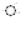
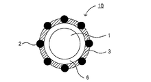
- FIG. 1 is a schematic cross-sectional view showing an example of the composite active material of the present invention.
- a composite active material 10 shown in FIG. 1 has an active material 1 and a coat layer 3 that covers the surface of the active material 1 and fine particles 2 are arranged on the surface.
- the fine particles 2 have a particle size smaller than that of the active material 1 and contain Si.
- a coat layer 3 covers the surface of the active material 1 and contains an undercoat layer 4 containing Si, and a fine particle fixing layer 5 that is formed on the undercoat layer 4 and fixes the fine particles 2.
- the composite active material of the present invention will be described for each configuration.
- the coat layer in the present invention covers the surface of the active material, and fine particles are arranged on the surface.
- the contact between the composite active materials or between the composite active material and the wall of the apparatus can be point contact, and the contact area can be reduced. Can be small.
- the coating layer covers the surface of the active material, so that the reaction between the active material and the electrolyte material can be suppressed.
- a high resistance layer can be formed at the interface between the active material and the sulfide solid electrolyte material. Can be suppressed.
- the coat layer in the present invention covers the surface of the active material and includes an undercoat layer containing Si, and a fine particle fixing layer that is formed on the undercoat layer and fixes fine particles (first aspect), It can be divided into two modes: a mode in which fine particles are in contact with the active material (second mode).
- first aspect a mode in which fine particles are in contact with the active material (second mode).
- the 1st aspect of the coat layer in this invention is the base coat layer which coat
- the coat layer 3 covers the surface of the active material 1 and is formed on the base coat layer 4 containing Si and the base coat layer 4 to fix the fine particles 2.
- Layer 5 covers the surface of the active material 1 and is formed on the base coat layer 4 containing Si and the base coat layer 4 to fix the fine particles 2.
- the undercoat layer in this embodiment covers the surface of the active material and contains Si.
- the undercoat layer is not particularly limited as long as it contains Si and can suppress the reaction between the active material and the electrolyte material, but it preferably has ion conductivity. This is because the resistance at the surface of the active material can be lowered by the conduction of ions inside the undercoat layer.
- Examples of the material for such an undercoat layer include Si-containing ion conductive oxides, Si-containing ion conductive sulfides, Si-containing ion conductive polymers, and the like. Things are preferred.
- the Si-containing ion conductive oxide examples include Li 4 SiO 4 and Li 2 SiO 3 .
- the undercoat layer may be composed of a composite compound of an Si-containing ion conductive oxide and an Si-free ion conductive oxide.
- examples of the ion conductive oxide not containing Si include Li 3 PO 4 , Li 3 BO 3 , Li 2 SO 4 , LiBO 2 , Examples include LiPO 3 , LiWO 4 , Li 2 MoO 4 , Li 2 ZrO 3 , Li 2 AlO 3 , Li 2 TiO 3 , Li 4 Ti 5 O 12 , LATP, LAGP, LiPON, and the like.
- Specific examples of such a composite compound include Li 4 SiO 4 —Li 3 BO 3 , Li 4 SiO 4 —Li 3 PO 4, and the like.
- Li 4 SiO 4 for example, can be synthesized using a raw material composition containing a Si alkoxide and Li ion source compound will be described later.
- the thickness of the undercoat layer is preferably a thickness that does not cause a reaction between the active material and the electrolyte material, and is preferably in the range of 1 nm to 500 nm, for example, in the range of 2 nm to 100 nm. More preferably. This is because the reaction between the active material and an electrolyte material such as a sulfide solid electrolyte material can be effectively suppressed within the above range.
- the undercoat layer preferably covers a larger area on the surface of the active material, and more preferably covers the entire surface of the active material. Specifically, the coverage is preferably 40% or more, more preferably 70% or more, and further preferably 90% or more.
- TEM etc. can be mentioned, for example, As a measuring method of the coverage of a base coat layer, TEM, XPS, etc. can be mentioned, for example.
- the fine particle fixing layer in this embodiment is formed on the undercoat layer and fixes fine particles.
- the contact of the composite active material becomes point contact at the fine particle apex, so that, for example, the contact area with the wall of the device and other active materials can be reduced, and during the mixing / dispersing process For example, the shearing force applied to the active material can be reduced, and cracking and peeling of the undercoat layer can be suppressed.
- the fine particle fixing layer can suppress the reaction between the active material and the electrolyte material, similarly to the base coat layer.
- the fine particles in this embodiment are fixed to the fine particle fixed layer, have a particle size smaller than the particle size of the active material, and contain Si.
- the fine particles since the fine particles are embedded in the fine particle fixed layer, they do not fall out of the fine particle fixed layer even when a force such as compression or shear is applied.
- the fine particles may be arranged so that at least a part thereof protrudes from the surface of the fine particle fixed layer, and may be included in the fine particle fixed layer.
- the fine particles are preferably arranged so that a part of the fine particles protrudes from the surface of the fine particle fixed layer and is in contact with the base coat layer.
- the fine particles in this embodiment contain Si, but usually further contain O, and specifically, a polymer obtained by the following reaction formula (1) and reaction formula (2). is there.
- R represents an organic functional group. Since this polymer uses Si alkoxide as a starting material and undergoes a hydrolysis reaction (reaction formula (1)) and a polymerization reaction (reaction formula (2)), and finally becomes SiO 2 . Although made of SiO 2, it may contain the R from the generation process thereof. Examples of R include -C 2 H 5 , -CH 3 , -C 3 H 7 and the like.
- the particle size of the fine particles is not particularly limited as long as it is smaller than the particle size of the active material.
- it is preferably in the range of 2 nm to 500 nm, more preferably in the range of 5 nm to 100 nm. preferable.
- the fine particle fixed layer usually has the same constituent elements as the undercoat layer. However, with the formation of the fine particles, the composition of the fine particle fixed layer is considered to deviate from the composition of the undercoat layer. In this embodiment, since the constituent elements of the fine particle fixing layer and the undercoat layer are the same, the affinity between the fine particle fixing layer and the undercoat layer can be improved.
- the fine particle fixing layer may be formed on the entire surface of the active material coated with the base coat layer, or may be formed on a part thereof.
- a virtual plane passing through the apex of the fine particle 2 (the side farthest from the active material 1) is A, and the center of gravity of the fine particle 2
- the virtual plane passing through B is B
- the virtual plane C including the tangent line (tangent circle) between the fine particles 2 and the fine particle fixed layer 5 exists between the virtual plane A and the virtual plane B.
- FIG. 2 is an explanatory diagram for explaining an example of the fine particle fixing layer in the composite active material having the coating layer of the first aspect.
- the reference numerals not described in FIG. 2 are the same as those in FIG.
- the thickness of the fine particle fixing layer is, for example, preferably in the range of 1 nm to 250 nm, and more preferably in the range of 3 nm to 50 nm.
- Examples of the method for measuring the thickness of the fine particle fixed layer include TEM.
- Examples of the method for forming the fine particle fixed layer include a method for performing the fine particle fixed layer forming process described in “B. Production method of composite active material 1. Coat layer forming step (1) First aspect” described later. Can do.
- the base coat layer is formed by the base coat layer forming process described in “B. Manufacturing method of composite active material 1.
- the composite active material having the coating layer of this embodiment may be such that an auxiliary coating layer, which will be described later, is formed in advance so as to cover the surface of the active material, and the coating layer is formed on the auxiliary coating layer. good.
- the auxiliary coating layer By having the auxiliary coating layer, the reaction between the active material and the electrolyte material can be further suppressed.
- the 2nd aspect of the coat layer in this invention is an aspect which is a single layer which microparticles
- the coat layer 3 is a single layer in which the fine particles 2 are in contact with the active material 1.
- FIG. 3 is a schematic cross-sectional view showing an example of the composite active material having the coat layer of the second embodiment, and the reference numerals not described are the same as those in FIG.
- the fine particles in this embodiment are in contact with the active material, have a particle size smaller than the particle size of the active material, and contain Si.
- the fine particles since the fine particles are embedded in the coat layer, they do not fall out of the coat layer even when a force such as compression or shear is applied.
- the fine particles may be disposed so that at least a part thereof protrudes from the surface of the coat layer, and may be included in the coat layer. Since the other points of the fine particles are the same as those of the fine particles in the first aspect described above, description thereof is omitted here.
- the coat layer of this embodiment is usually the same as the fine particle fixed layer in the first embodiment described above. Further, the coat layer may be formed on the entire surface of the active material, or may be formed on a part thereof, but is preferably formed on the entire surface. This is because the reaction between the active material and the electrolyte material can be further suppressed. Moreover, when the said coating layer is formed in a part of active material surface, it is preferable that the auxiliary
- the thickness of the coating layer of this embodiment is preferably in the range of 1 nm to 250 nm, for example, and more preferably in the range of 3 nm to 50 nm.
- TEM etc. can be mentioned, for example.
- Examples of the method for forming the coat layer according to this aspect include a method for performing a coat layer forming process described in “B. Production method of composite active material 1. Coat layer forming step (2) Second aspect” described later. be able to.
- the composite active material having the coating layer of this embodiment is formed such that the auxiliary coating layer 6 covers the surface of the active material 1 inside the coating layer 3. preferable. This is because the reaction between the active material and the electrolyte material can be further suppressed by having the auxiliary coating layer. Moreover, there is an advantage that the range of material selection for the coating material is widened.
- the auxiliary coat layer is not particularly limited as long as it can suppress the reaction between the active material and the electrolyte material, but preferably has an ionic conductivity. It is because the resistance on the surface of the active material can be lowered by the conduction of ions inside the auxiliary coating layer. Examples of the material for such an auxiliary coat layer include an ion conductive oxide.
- the ion conductive oxide preferably has a Li element, an A element, and an O element.
- the A is not particularly limited, and examples thereof include P, B, S, W, Mo, Zr, Al, and Ti.
- specific examples of such ion conductive oxide include Li 3 PO 4 , Li 3 BO 3 , Li 2 SO 4 , LiBO 2 , LiPO 3 , LiWO 4 , Li 2 MoO 4 , Li 2 ZrO 3 , Examples include Li 2 AlO 3 , Li 2 TiO 3 , Li 4 Ti 5 O 12 , LATP, LAGP, LiPON, and the like.
- FIG. 4 is a schematic cross-sectional view showing another example of the composite active material having the coat layer of the second embodiment, and the reference numerals not described are the same as those in FIG.
- the thickness of the auxiliary coat layer is preferably in the range of 1 nm to 10 nm, for example. Further, the auxiliary coating layer preferably covers a larger area of the surface of the active material, and more preferably covers the entire surface of the active material. Examples of the method for forming the auxiliary coating layer on the surface of the active material include a rolling fluidized coating method, a mechanofusion method, a CVD method, and a PVD method.
- the active material in the present invention usually reacts with an electrolyte material. Moreover, the said active material changes with kinds of the conductive ion of the battery in which the target composite active material is used. For example, when the composite active material of the present invention is used in a lithium secondary battery, the active material occludes / releases lithium ions.
- the active material in the present invention may be a positive electrode active material or a negative electrode active material.
- the positive electrode active material used in the present invention is not particularly limited as long as it reacts with an electrolyte material such as a sulfide solid electrolyte material.
- M is preferably at least one selected from the group consisting of Co, Mn, Ni, V and Fe, and preferably at least one selected from the group consisting of Co, Ni and Mn. More preferred.
- an oxide positive electrode active material specifically, a rock salt layered active material such as LiCoO 2 , LiMnO 2 , LiNiO 2 , LiVO 2 , LiNi 1/3 Co 1/3 Mn 1/3 O 2 , Examples thereof include spinel active materials such as LiMn 2 O 4 and Li (Ni 0.5 Mn 1.5 ) O 4 .
- the oxide positive electrode active material other than the above general formula Li x M y O z include olivine type active materials such as LiFePO 4 and LiMnPO 4 .
- Si-containing oxides such as Li 2 FeSiO 4 and Li 2 MnSiO 4 may be used as the positive electrode active material.
- the shape of the positive electrode active material examples include a particle shape, and among them, a true spherical shape or an elliptical spherical shape is preferable.
- the positive electrode active material has a particle shape, the average particle diameter is preferably in the range of 0.1 ⁇ m to 50 ⁇ m, for example.
- examples of the negative electrode active material used in the present invention include Nb 2 O 5 , Li 4 Ti 5 O 12 , SiO 2 , and SnO 2 .
- the shape of the negative electrode active material examples include a particle shape, and among them, a true spherical shape or an elliptical spherical shape is preferable.
- the average particle diameter is preferably in the range of 0.1 ⁇ m to 50 ⁇ m, for example.
- the composite active material of the present invention is usually used for a battery, and preferably used for an all-solid battery. Since the coating layer covering the surface of the active material is not easily cracked or peeled off at the time of battery production, the formation of a high resistance layer at the interface between the active material and a solid electrolyte material such as a sulfide solid electrolyte material, This is because an all-solid battery that can be sufficiently suppressed by the coating layer and has excellent output characteristics can be obtained.
- the method for producing the composite active material of the present invention is not particularly limited as long as it is a method capable of obtaining the above-described composite active material.
- “B. Production method of composite active material” described later is used. Can be mentioned.
- the method for producing a composite active material of the present invention includes an active material and a coating layer that covers the surface of the active material and fine particles are arranged on the surface, and the fine particles are larger than the particle size of the active material.
- a method for producing a composite active material having a small particle diameter and containing Si, wherein a coating layer forming coating solution containing Si is applied to the active material to form the coat layer It has a layer forming step.
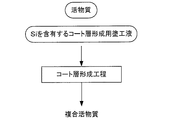
- FIG. 5 is a flowchart showing an example of the method for producing a composite active material of the present invention.
- an active material and a coating liquid for forming a coat layer containing Si are prepared.
- a coating layer forming coating solution containing Si is applied to the active material, and particles having a particle size smaller than the particle size of the active material are disposed on the surface.
- a coating layer covering the surface of the material is formed (coating layer forming step) to obtain a composite active material.
- the coat layer forming step in the present invention is a step of coating the active material with a coating layer forming coating solution containing Si to form a coat layer.
- a coating solution for forming a coating layer is applied to the surface of the active material to cover the surface of the active material, and an undercoat layer containing Si is formed.
- the undercoat layer forming process to be formed and the undercoat layer forming process are continuously performed, and the coating layer forming coating liquid after the start of polymerization is applied onto the undercoat layer, and fine particles are formed on the undercoat layer.
- the coating layer forming coating solution is formed at the same time as or after the start of the polymerization of the coating layer forming coating solution. It can be divided into two modes, that is, a mode (second mode) in which a coating layer forming process is performed in which the active material is coated on the surface to form a single-layered coating layer in which the fine particles are in contact with the active material.
- a mode second mode in which a coating layer forming process is performed in which the active material is coated on the surface to form a single-layered coating layer in which the fine particles are in contact with the active material.
- the surface of the active material is coated with a coating layer forming coating liquid after completion of hydrolysis and before the start of polymerization.
- the coating solution for forming the coating layer after the start of polymerization is applied on the underlying coating layer continuously from the underlying coating layer forming treatment and the underlying coating layer forming treatment for forming the underlying coating layer containing Si.
- a coat layer is formed which covers the surface of the active material and has a base coat layer containing Si and a fine particle fixing layer formed on the base coat layer and fixing fine particles. Can do.
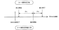
- FIG. 6 is an explanatory diagram for explaining an example of the coating layer forming step of the first aspect.
- a coating layer forming coating solution (sol-gel solution) is prepared.
- spraying and drying of the coating layer forming coating solution onto the surface of the active material 1 is started, and the coating layer forming coating solution is started.
- the surface of the active material 1 is coated to form the base coat layer 4 containing Si (base coat layer forming process).
- the coating solution for forming the coating layer is continuously sprayed and dried. After a predetermined time has elapsed, the coating solution for forming the coating layer is sprayed and dried.
- the fine particle fixing layer 5 that is formed on the base coat layer 4 and fixes the fine particles 2 is the time from the start of the polymerization of the coating liquid for forming the coating layer to the end of spraying and drying of the coating liquid for forming the coating layer. Forming (fine particle fixed layer forming process), the coat layer 3 having the base coat layer 4 and the fine particle fixed layer 5 is formed.
- the coating layer forming coating solution (sol-gel solution) used in this embodiment usually starts polymerization after completion of hydrolysis.
- the process time ⁇ t 1 from the start of coating of the coating solution for forming a coat layer to the start of polymerization and the process from the start of polymerization of the coating solution for forming a coat layer to the end of coating By adjusting the time ⁇ t 2 , a desired coat layer can be easily formed using a coating apparatus. For example, if ⁇ t 1 is made sufficiently large, an undercoat layer is formed. On the other hand, if ⁇ t 1 is made sufficiently small or the coating start of the coating solution for forming a coat layer is made later than the start of polymerization, the undercoat layer is formed.
- a coat layer is not formed. Further, if ⁇ t 2 is sufficiently large, a fine particle fixed layer is formed. On the other hand, if ⁇ t 2 is sufficiently small or if the application of the coating layer forming coating liquid is made earlier than the start of polymerization, the fine particles are formed. A fixed layer is not formed. By forming the fine particle fixing layer without forming the base coat layer, the same coating layer as that of the second aspect described later can be formed.
- Examples of the method for determining the completion of hydrolysis of the coating liquid for forming the coating layer include chemical analysis such as gas chromatography and infrared spectroscopic analysis, viscoelasticity measurement, and evaluation of film forming properties on a substrate such as glass. Mention may be made of physical methods. If the hydrolysis of the coating layer forming coating solution is completed, it is considered that the Si alkoxide and the conductive ion source compound are not present in the solvent and have a uniform composition.
- examples of the method for determining the start of polymerization of the coating layer forming coating solution include a method of forming a coating layer forming coating solution on a glass substrate and observing the film with an optical microscope or an electron microscope. be able to.
- the stage at which the fine particles are observed can be determined as the time of starting the polymerization.
- the concentration of the Si alkoxide and conductive ion source compound in the coating layer forming coating solution, the amount of water added during hydrolysis, or the temperature of the coating layer forming coating solution is adjusted. And so on.
- measure the timing of hydrolysis completion and polymerization start at several temperatures in advance, and draw a calibration curve according to the Arrhenius equation. Completion of hydrolysis at temperature and timing of initiation of polymerization can be predicted.
- the coating layer forming coating solution used in this embodiment contains Si, and is usually a sol-gel solution obtained by dissolving or uniformly dispersing a Si alkoxide and a conductive ion source compound in a solvent.
- Si alkoxide include tetraethoxysilane, tetramethoxysilane, and tetrapropoxysilane.
- the conductive ion source compound include Li alkoxides such as lithium ethoxide and lithium methoxide, lithium acetate, and lithium hydroxide when the conductive ions are Li ions.
- examples of the solvent include ethanol.
- composite active material can be mentioned.
- tetraethoxysilane as the Si alkoxide and lithium acetate as the conductive ion source compound from the viewpoint of controllability of hydrolysis completion time and polymerization start time of the coating layer forming coating solution.
- the coating liquid for forming the coat layer is applied to the surface of the active material, and the formation of the coat layer after the start of polymerization in the fine particle fixed layer formation treatment
- the coating liquid for coating is applied on the undercoat layer.
- a coating method of the coating layer forming coating solution a fluidized bed coating method is usually used.
- the fluidized bed coating method is a film coating technique using a fluidized bed granulation / coating apparatus, and a uniform coating can be applied by repeating spraying and drying of liquid on particles. Examples of such an apparatus include a multiplex manufactured by Paulek and a flow coater manufactured by Freund Corporation.
- the coating layer forming coating liquid after completion of hydrolysis and before the start of polymerization is applied to the surface of the active material by using a fluidized bed coating method, so that fine particles are not generated.
- a coat layer is formed, and a fine particle fixed layer is formed while fine particles are generated by applying a coating solution for forming a coat layer after the start of polymerization onto the base coat layer.
- the fine particle fixing layer is formed on the entire surface or partially formed on the active material coated with the coat layer is considered to depend on the polymerization rate of the coating liquid for forming the coat layer. In a system with a high polymerization rate, there is no time for polymer formation and the entire surface cannot be covered, so that the fine particle fixed layer is partially formed. On the other hand, in a system with a low polymerization rate, there is a time allowance for polymer formation and the entire surface can be coated, so that the fine particle fixed layer is formed on the entire surface.
- the coating layer forming coating solution is applied to the surface of the active material simultaneously with or after the start of the polymerization of the coating layer forming coating solution.
- This is an embodiment having a coating layer forming process for forming a single layer of coating layer in which fine particles are in contact with the active material.
- a single layer coat layer in which fine particles are in contact with the active material can be formed.
- FIG. 8 is an explanatory diagram for explaining an example of the coating layer forming process of the second embodiment.
- a coating layer forming coating solution (sol-gel solution) is prepared.
- spraying and drying of the coating liquid for forming the coating layer on the surface of the active material 1 is started.
- the coating liquid for forming the coating layer is formed as a single layer in which the fine particles 2 are in contact with the active material 1 in the time from the start of spraying / drying of the coating liquid for coating layer formation to the end of spraying / drying (coating). Layer formation process).
- the coating layer forming coating solution and the active material used in this embodiment are the same as those in the first embodiment described above, description thereof is omitted here.
- the coating layer forming coating solution is applied to the surface of the active material at the same time as or after the start of polymerization of the coating layer forming coating solution.
- the method for determining the start of polymerization and the method for applying the coating liquid for forming a coat layer are the same as in the first aspect described above.
- the coating layer forming coating solution is applied to the surface of the active material at the same time as or after the start of polymerization of the coating layer forming coating solution by using a fluidized bed coating method. As a result, a coat layer is formed.
- Composite active material The use and the like of the composite active material obtained by the method for producing a composite active material of the present invention are the same as those described in “A. Composite active material” above, so description thereof is omitted here.
- the battery of the present invention includes a positive electrode active material layer containing a positive electrode active material, a negative electrode active material layer containing a negative electrode active material, an electrolyte layer formed between the positive electrode active material layer and the negative electrode active material layer, In the battery, at least one of the positive electrode active material layer and the negative electrode active material layer contains the composite active material described above.
- the present invention by using the above-described composite active material, it is possible to prevent the coat layer from being cracked or peeled off from the active material during battery production. As a result, the reaction between the active material and the electrolyte material can be suppressed by the coat layer, and a battery having excellent output characteristics can be obtained.
- FIG. 9 is a schematic cross-sectional view showing an example of the battery of the present invention.
- a battery 20 shown in FIG. 9 includes a positive electrode active material layer 11, a negative electrode active material layer 12, an electrolyte layer 13 formed between the positive electrode active material layer 11 and the negative electrode active material layer 12, and a positive electrode active material layer 11.
- the present invention is greatly characterized in that at least one of the positive electrode active material layer 11 and the negative electrode active material layer 12 contains the composite active material described above.
- the battery of this invention is demonstrated for every structure.
- the positive electrode active material layer in the present invention is a layer containing at least a positive electrode active material.
- the positive electrode active material layer may contain at least one of a conductive material, a binder, and a solid electrolyte material in addition to the positive electrode active material.
- the positive electrode active material layer preferably contains a solid electrolyte material. This is because the solid electrolyte layer is less likely to penetrate into the positive electrode active material layer than the liquid electrolyte layer (electrolytic solution), and the ion conductivity inside the positive electrode active material layer may be lowered. By adding the solid electrolyte material, the ion conductivity of the positive electrode active material layer can be easily improved.
- the positive electrode active material is preferably the composite active material described above.
- the positive electrode active material layer in the present invention contains a sulfide solid electrolyte material, the effects of the present invention can be sufficiently exhibited.
- the content of the positive electrode active material in the positive electrode active material layer is, for example, preferably in the range of 10% by mass to 99% by mass, and more preferably in the range of 20% by mass to 90% by mass.
- the conductive material is not particularly limited as long as it has desired electronic conductivity, and examples thereof include a carbon material.
- specific examples of the carbon material include acetylene black, ketjen black, carbon black, coke, carbon fiber, and graphite.
- the binder is not particularly limited as long as it is chemically and electrically stable.
- fluorine-based binders such as polyvinylidene fluoride (PVDF) and polytetrafluoroethylene (PTFE) are usable.
- PVDF polyvinylidene fluoride
- PTFE polytetrafluoroethylene
- examples thereof include an adhesive and a rubber-based binder such as styrene butadiene rubber.
- the solid electrolyte material is not particularly limited as long as it has desired ionic conductivity, and examples thereof include oxide solid electrolyte materials and sulfide solid electrolyte materials.
- the solid electrolyte material will be described later in “3. Electrolyte layer”.
- the thickness of the positive electrode active material layer varies greatly depending on the battery configuration, but is preferably in the range of 0.1 ⁇ m to 1000 ⁇ m, for example.
- the negative electrode active material layer in the present invention is a layer containing at least a negative electrode active material.
- the negative electrode active material layer may contain at least one of a conductive material, a binder, and a solid electrolyte material in addition to the negative electrode active material.
- the negative electrode active material layer preferably contains a solid electrolyte material. This is because the solid electrolyte layer is less likely to penetrate into the negative electrode active material layer than the liquid electrolyte layer (electrolytic solution), and the ionic conductivity inside the negative electrode active material layer may be lowered. By adding the solid electrolyte material, the ion conductivity of the negative electrode active material layer can be easily improved.
- the composite active material described above can be used as the negative electrode active material used in the present invention.
- a metal active material and a carbon active material can be used as a negative electrode active material, for example.
- the metal active material include In, Al, Si, and Sn.
- examples of the carbon active material include mesocarbon microbeads (MCMB), highly oriented graphite (HOPG), hard carbon, and soft carbon.
- the content of the negative electrode active material in the negative electrode active material layer is, for example, preferably in the range of 10% by mass to 99% by mass, and more preferably in the range of 20% by mass to 90% by mass.
- the conductive material, the binder, and the solid electrolyte material used for the negative electrode active material layer are the same as those in the positive electrode active material layer described above.
- the thickness of the negative electrode active material layer varies greatly depending on the configuration of the battery, but is preferably in the range of 0.1 ⁇ m to 1000 ⁇ m, for example.
- the electrolyte layer in the present invention is a layer formed between the positive electrode active material layer and the negative electrode active material layer and containing at least an electrolyte material. Ion conduction between the positive electrode active material and the negative electrode active material is performed through the electrolyte material included in the electrolyte layer.
- the form of the electrolyte layer is not particularly limited, and examples thereof include a liquid electrolyte layer, a gel electrolyte layer, a solid electrolyte layer, and the like. Among these, a solid electrolyte layer is preferable. It is because it can be set as the battery excellent in safety
- the solid electrolyte layer is a layer made of a solid electrolyte material.
- the solid electrolyte material include an oxide solid electrolyte material and a sulfide solid electrolyte material.
- the solid electrolyte material is preferably a sulfide solid electrolyte material. This is because a high output battery with high Li ion conductivity can be obtained.
- the sulfide solid electrolyte material having Li ion conductivity include those having Li, S, and the third component A.
- the third component A include at least one selected from the group consisting of P, Ge, B, Si, I, Al, Ga, and As.
- the sulfide solid electrolyte material is preferably a compound using Li 2 S and sulfide MS other than Li 2 S.
- Specific examples include a Li 2 S—P 2 S 5 compound, a Li 2 S—SiS 2 compound, a Li 2 S—GeS 2 compound, etc.
- a Li 2 S—P 2 S 5 compound is preferable. This is because the Li ion conductivity is high.
- the “Li 2 S—P 2 S 5 compound” means a sulfide solid electrolyte material using a raw material composition containing Li 2 S and P 2 S 5, and the same applies to other compounds.
- the content of the solid electrolyte material in the solid electrolyte layer is not particularly limited as long as a desired insulating property can be obtained.
- the content is in the range of 10% by mass to 100% by mass, and especially 50% by mass. It is preferably in the range of ⁇ 100% by mass.
- the solid electrolyte layer may contain a binder.
- the binder used for a solid electrolyte layer it is the same as that of the case in the positive electrode active material layer mentioned above.
- the liquid electrolyte layer is usually a layer using a non-aqueous electrolyte.
- the type of the non-aqueous electrolyte varies depending on the type of battery.
- the non-aqueous electrolyte of a lithium battery usually contains a lithium salt and a non-aqueous solvent.
- the lithium salt include inorganic lithium salts such as LiPF 6 , LiBF 4 , LiClO 4 and LiAsF 6 ; and LiCF 3 SO 3 , LiN (CF 3 SO 2 ) 2 , LiN (C 2 F 5 SO 2 ) 2 , An organic lithium salt such as LiC (CF 3 SO 2 ) 3 can be used.
- non-aqueous solvent examples include ethylene carbonate (EC), propylene carbonate (PC), dimethyl carbonate (DMC), diethyl carbonate (DEC), ethyl methyl carbonate (EMC), butylene carbonate (BC), ⁇ -butyrolactone, and sulfolane. , Acetonitrile, 1,2-dimethoxymethane, 1,3-dimethoxypropane, diethyl ether, tetrahydrofuran, 2-methyltetrahydrofuran, and mixtures thereof.
- concentration of the lithium salt in the non-aqueous electrolyte is, for example, in the range of 0.5 mol / L to 3 mol / L.
- a low-volatile liquid such as an ionic liquid may be used as the non-aqueous electrolyte.
- the gel electrolyte layer can be obtained, for example, by adding a polymer to a non-aqueous electrolyte and gelling. Specifically, gelation can be performed by adding a polymer such as polyethylene oxide (PEO), polyacrylonitrile (PAN), or polymethyl methacrylate (PMMA) to the nonaqueous electrolytic solution.
- a polymer such as polyethylene oxide (PEO), polyacrylonitrile (PAN), or polymethyl methacrylate (PMMA)
- the thickness of the electrolyte layer varies greatly depending on the type of electrolyte and the configuration of the battery.
- the thickness is preferably in the range of 0.1 ⁇ m to 1000 ⁇ m, and preferably in the range of 0.1 ⁇ m to 300 ⁇ m. More preferred.
- the battery of the present invention has at least the positive electrode active material layer, the negative electrode active material layer, and the solid electrolyte layer described above. Furthermore, it usually has a positive electrode current collector for collecting current of the positive electrode active material layer and a negative electrode current collector for collecting current of the negative electrode active material layer.
- Examples of the material for the positive electrode current collector include SUS, aluminum, nickel, iron, titanium, and carbon. Among them, SUS is preferable.
- examples of the material for the negative electrode current collector include SUS, copper, nickel, and carbon. Among them, SUS is preferable.
- the thickness and shape of the positive electrode current collector and the negative electrode current collector are preferably appropriately selected according to the use of the battery.
- the battery of the present invention may have a separator between the positive electrode active material layer and the negative electrode active material layer. This is because a battery with higher safety can be obtained.
- the material for the separator include porous films such as polyethylene, polypropylene, cellulose, and polyvinylidene fluoride; and nonwoven fabrics such as a resin nonwoven fabric and a glass fiber nonwoven fabric.
- the battery case of a general battery can be used for the battery case used for this invention. Examples of the battery case include a SUS battery case.
- Battery Examples of the battery of the present invention include a lithium battery, a sodium battery, a magnesium battery, and a calcium battery. Among these, a lithium battery and a sodium battery are preferable, and a lithium battery is particularly preferable.
- the battery of the present invention may be a primary battery or a secondary battery, but among them, a secondary battery is preferable. This is because it can be repeatedly charged and discharged and is useful, for example, as a vehicle-mounted battery.
- Examples of the shape of the battery of the present invention include a coin type, a laminate type, a cylindrical type, and a square type.
- the manufacturing method of the battery of this invention will not be specifically limited if it is a method which can obtain the battery mentioned above, The method similar to the manufacturing method of a general battery can be used.
- the battery of the present invention is an all-solid battery, for example, by sequentially pressing the material constituting the positive electrode active material layer, the material constituting the electrolyte layer (solid electrolyte layer), and the material constituting the negative electrode active material layer
- a method of producing a power generation element, housing the power generation element inside the battery case, and caulking the battery case can be exemplified.
- the present invention is not limited to the above embodiment.
- the above-described embodiment is an exemplification, and the present invention has substantially the same configuration as the technical idea described in the claims of the present invention, and any device that exhibits the same function and effect is the present invention. It is included in the technical scope of the invention.
- a coating solution for forming a coat layer was prepared using boric acid, TEOS (tetraethoxysilane), lithium acetate, and ethanol.
- boric acid and TEOS are dissolved and uniformly decomposed in ethanol, and then the two solutions are mixed so that B and Si are in an element ratio (molar ratio) of 1: 1, and stirred until they are uniformly mixed.
- an ethanol solution of lithium acetate was prepared and mixed with the above mixed solution containing B and Si so that the weight ratio of boric acid and lithium acetate was 2:23.
- the amount of ethanol was adjusted so that the solid content ratio of the solution was 6.4 wt%, and a coating layer forming coating solution was obtained.
- the composition of the coating layer forming coating solution is capable of forming Li 4 SiO 4 —Li 3 BO 3 .
- boric acid for example, side reactions can be suppressed and the hydrolysis of TEOS can be easily controlled as compared with the case where B alkoxide is used.
- the active material LiNi 1/3 Co 1/3 Mn 1/3 O 2 , Nichia after 10 hours passed, based on the time when the ethanol solution of lithium acetate and the ethanol solution of boric acid and TEOS were mixed.
- Spraying and drying of the coating layer forming coating solution on the surface of Chemical were started. After 9 hours from the start of spraying of the coating layer forming coating solution, spraying / drying was terminated to obtain a composite active material.
- MP-01 manufactured by POWREC
- 1610 g of coating layer forming coating solution was sprayed on 1 kg of the active material.
- hydrolysis of the coating layer forming coating solution was completed after 10 hours on the basis of the time when the ethanol solution of lithium acetate and the ethanol solution of boric acid and TEOS were mixed. After 13 hours, the coating was completed. Polymerization of the layer forming coating solution started.
- Example 1 The composite active material obtained in Example 1 was observed with a scanning electron microscope (SEM). The obtained SEM image is shown in FIG. As shown in FIG. 10, it was confirmed that fine particles having a particle size smaller than that of the active material are arranged on the surface of the active material.
- SEM scanning electron microscope
- Example 2 Based on the mixing time of the ethanol solution of lithium acetate and the ethanol solution of boric acid and TEOS, the active material (LiNi 1/3 Co 1/3 Mn 1/3 O 2 , manufactured by Nichia) after 15 hours A composite active material was obtained in the same manner as in Example 1 except that spraying / drying of the coating layer forming coating solution on the surface of the coating was started. When the composite active material obtained in Example 2 was observed by SEM, it was confirmed that fine particles having a particle size smaller than that of the active material were arranged on the surface of the active material, as in Example 1.
Landscapes
- Chemical & Material Sciences (AREA)
- Chemical Kinetics & Catalysis (AREA)
- Electrochemistry (AREA)
- General Chemical & Material Sciences (AREA)
- Composite Materials (AREA)
- Inorganic Chemistry (AREA)
- Engineering & Computer Science (AREA)
- Manufacturing & Machinery (AREA)
- Battery Electrode And Active Subsutance (AREA)
- Secondary Cells (AREA)
Abstract
Description
まず、本発明の複合活物質について説明する。本発明の複合活物質は、活物質と、上記活物質の表面を被覆し、微粒子が表面に配置されたコート層とを有する複合活物質であって、上記微粒子が、上記活物質の粒径よりも小さい粒径を有し、Siを含有することを特徴とするものである。
以下、本発明の複合活物質について、構成ごとに説明する。
まず、本発明におけるコート層について説明する。本発明におけるコート層は、活物質の表面を被覆し、微粒子が表面に配置されたものである。本発明においては、コート層の表面に微粒子が配置されていることにより、例えば、複合活物質同士、または複合活物質と装置の壁等との接触を点接触とすることができ、接触面積を小さくすることができる。また、コート層が活物質の表面を被覆することで、活物質と電解質材料との反応を抑制することができ、例えば、活物質と硫化物固体電解質材料との界面における高抵抗層の形成を抑制することができる。
本発明におけるコート層の第1態様は、活物質の表面を被覆し、Siを含有する下地コート層と、下地コート層上に形成され、微粒子を固定する微粒子固定層とを有する態様である。上述した図1に示されるように、コート層3は、活物質1の表面を被覆し、Siを含有する下地コート層4と、下地コート層4上に形成され、微粒子2を固定する微粒子固定層5とを有する。

本発明におけるコート層の第2態様は、活物質に微粒子が接する単一層である態様である。図3に示されるように、コート層3は、活物質1に微粒子2が接する単一層である。なお、図3は第2態様のコート層を有する複合活物質の一例を示す概略断面図であり、説明していない符号については、図1と同様である。
次に、本発明における活物質について説明する。本発明における活物質は、通常、電解質材料と反応するものである。また、上記活物質は、目的とする複合活物質が用いられる電池の伝導イオンの種類により異なるものである。例えば、本発明の複合活物質がリチウム二次電池に用いられる場合、活物質は、リチウムイオンを吸蔵・放出する。また、本発明における活物質は、正極活物質であっても良く、負極活物質であっても良い。
本発明の複合活物質は、通常、電池に用いられるものであり、中でも、全固体電池に用いられることが好ましい。電池作製時において、活物質の表面を被覆するコート層の割れや剥離が生じにくいため、活物質と、例えば、硫化物固体電解質材料等の固体電解質材料との界面における高抵抗層の形成を、コート層によって充分に抑制することができ、出力特性に優れた全固体電池を得ることができるからである。
次に、本発明の複合活物質の製造方法について説明する。本発明の複合活物質の製造方法は、活物質と、上記活物質の表面を被覆し、微粒子が表面に配置されたコート層とを有し、上記微粒子が、上記活物質の粒径よりも小さい粒径を有し、Siを含有する複合活物質の製造方法であって、上記活物質に、Siを含有するコート層形成用塗工液を塗工して、上記コート層を形成するコート層形成工程を有することを特徴とするものである。
本発明におけるコート層形成工程は、活物質に、Siを含有するコート層形成用塗工液を塗工して、コート層を形成する工程である。上記コート層形成工程は、加水分解完了後かつ重合開始前のコート層形成用塗工液を活物質の表面に塗工して、活物質の表面を被覆し、Siを含有する下地コート層を形成する下地コート層形成処理と、下地コート層形成処理から連続的に行われ、重合開始後のコート層形成用塗工液を下地コート層上に塗工して、下地コート層上に、微粒子を固定する微粒子固定層を形成する微粒子固定層形成処理とを有する態様(第1態様)と、コート層形成用塗工液の重合開始と同時またはそれ以降に、コート層形成用塗工液を活物質の表面に塗工して、活物質に微粒子が接する単一層のコート層を形成するコート層形成処理を有する態様(第2態様)との2つの態様に分けることができる。以下、各態様について説明する。
本発明におけるコート層形成工程の第1態様は、加水分解完了後かつ重合開始前のコート層形成用塗工液を活物質の表面に塗工して、活物質の表面を被覆し、Siを含有する下地コート層を形成する下地コート層形成処理と、下地コート層形成処理から連続的に行われ、重合開始後のコート層形成用塗工液を下地コート層上に塗工して、下地コート層上に、微粒子を固定する微粒子固定層を形成する微粒子固定層形成処理とを有する態様である。本態様のコート層形成工程により、活物質の表面を被覆し、Siを含有する下地コート層と、下地コート層上に形成され、微粒子を固定する微粒子固定層とを有するコート層を形成することができる。
本発明におけるコート層形成工程の第2態様は、コート層形成用塗工液の重合開始と同時またはそれ以降に、コート層形成用塗工液を活物質の表面に塗工して、活物質に微粒子が接する単一層のコート層を形成するコート層形成処理を有する態様である。本態様のコート層形成工程により、活物質に微粒子が接する単一層のコート層を形成することができる。
本発明の複合活物質の製造方法により得られる複合活物質の用途等については、上記「A.複合活物質」に記載した内容と同様であるので、ここでの記載は省略する。
次に、本発明の電池について説明する。本発明の電池は、正極活物質を含有する正極活物質層と、負極活物質を含有する負極活物質層と、上記正極活物質層および上記負極活物質層の間に形成された電解質層とを有する電池であって、上記正極活物質層および上記負極活物質層の少なくとも一方が、上述した複合活物質を含有することを特徴とするものである。
以下、本発明の電池について、構成ごとに説明する。
まず、本発明における正極活物質層について説明する。本発明における正極活物質層は、少なくとも正極活物質を含有する層である。また、正極活物質層は、正極活物質の他に、導電化材、結着材および固体電解質材料の少なくとも一つを含有していても良い。特に、本発明の電池が固体電解質層を有する全固体電池である場合は、正極活物質層が固体電解質材料を含有することが好ましい。固体電解質層は液体電解質層(電解液)に比べて、正極活物質層の内部に浸透しにくく、正極活物質層の内部のイオン伝導性が低くなる可能性があるからである。固体電解質材料を添加することで、正極活物質層のイオン伝導性を容易に向上させることができる。
次に、本発明における負極活物質層について説明する。本発明における負極活物質層は、少なくとも負極活物質を含有する層である。また、負極活物質層は、負極活物質の他に、導電化材、結着材および固体電解質材料の少なくとも一つを含有していても良い。特に、本発明の電池が固体電解質層を有する全固体電池である場合は、負極活物質層が固体電解質材料を含有することが好ましい。固体電解質層は液体電解質層(電解液)に比べて、負極活物質層の内部に浸透しにくく、負極活物質層の内部のイオン伝導性が低くなる可能性があるからである。固体電解質材料を添加することで、負極活物質層のイオン伝導性を容易に向上させることができる。
次に、本発明における電解質層について説明する。本発明における電解質層は、正極活物質層および負極活物質層の間に形成され、少なくとも電解質材料を含有する層である。電解質層に含まれる電解質材料を介して、正極活物質と負極活物質との間のイオン伝導を行う。電解質層の形態は、特に限定されるものではなく、液体電解質層、ゲル電解質層、固体電解質層等を挙げることができ、中でも、固体電解質層が好ましい。安全性に優れた電池とすることができるからである。
本発明の電池は、上述した正極活物質層、負極活物質層および固体電解質層を少なくとも有するものである。さらに通常は、正極活物質層の集電を行う正極集電体、および負極活物質層の集電を行う負極集電体を有する。正極集電体の材料としては、例えば、SUS、アルミニウム、ニッケル、鉄、チタンおよびカーボン等を挙げることができ、中でも、SUSが好ましい。一方、負極集電体の材料としては、例えば、SUS、銅、ニッケルおよびカーボン等を挙げることができ、中でも、SUSが好ましい。また、正極集電体および負極集電体の厚さや形状等については、電池の用途等に応じて適宜選択することが好ましい。
本発明の電池の種類としては、リチウム電池、ナトリウム電池、マグネシウム電池およびカルシウム電池等を挙げることができ、中でも、リチウム電池およびナトリウム電池が好ましく、特に、リチウム電池が好ましい。また、本発明の電池は、一次電池であっても良く、二次電池であっても良いが、中でも、二次電池であることが好ましい。繰り返し充放電でき、例えば、車載用電池として有用だからである。本発明の電池の形状としては、例えば、コイン型、ラミネート型、円筒型および角型等を挙げることができる。また、本発明の電池の製造方法は、上述した電池を得ることができる方法であれば特に限定されるものではなく、一般的な電池の製造方法と同様の方法を用いることができる。本発明の電池が全固体電池である場合、例えば、正極活物質層を構成する材料、電解質層(固体電解質層)を構成する材料、および負極活物質層を構成する材料を順次プレスすることにより、発電要素を作製し、この発電要素を電池ケースの内部に収納し、電池ケースをかしめる方法等を挙げることができる。
ホウ酸、TEOS(テトラエトキシシラン)、酢酸リチウム、エタノールを用いて、コート層形成用塗工液を調製した。まず、ホウ酸と、TEOSとをそれぞれエタノールに溶解・均一分解させた後に、BおよびSiが元素比(モル比)で1:1となるように2つの溶液を混合し、均一混合するまで撹拌を続けた。次に、酢酸リチウムのエタノール溶液を調製し、上記のBおよびSiを含む混合溶液と、ホウ酸および酢酸リチウムの重量比が2:23となるように混合した。さらに、溶液の固形分比率が6.4wt%になるようにエタノールの量を調整し、コート層形成用塗工液を得た。なお、上記コート層形成用塗工液の組成は、Li4SiO4-Li3BO3を形成可能なものである。なお、ホウ酸を用いることで、例えば、Bアルコキシドを用いた場合に比べて、副次反応を抑制することができ、TEOSの加水分解を制御しやすい。
続いて、酢酸リチウムのエタノール溶液と、ホウ酸およびTEOSのエタノール溶液とを混合した時間を基準に、10時間経過後に活物質(LiNi1/3Co1/3Mn1/3O2、日亜化学製)の表面への上記コート層形成用塗工液の噴霧・乾燥を開始した。コート層形成用塗工液の噴霧開始から9時間経過後に噴霧・乾燥を終了し、複合活物質を得た。この際、コーティング装置にはMP-01(パウレック製)を用いて、活物質1kgに対してコート層形成用塗工液1610gを噴霧した。なお、酢酸リチウムのエタノール溶液と、ホウ酸およびTEOSのエタノール溶液とを混合した時間を基準に、10時間経過後に上記コート層形成用塗工液の加水分解が完了し、13時間経過後に上記コート層形成用塗工液の重合が開始した。
酢酸リチウムのエタノール溶液と、ホウ酸およびTEOSのエタノール溶液とを混合した時間を基準に、15時間経過後に活物質(LiNi1/3Co1/3Mn1/3O2、日亜化学製)の表面への上記コート層形成用塗工液の噴霧・乾燥を開始したこと以外は、実施例1と同様にして、複合活物質を得た。実施例2で得られた複合活物質をSEMで観察したところ、実施例1と同様に、活物質の表面に活物質よりも粒径が小さい微粒子が配置されていることが確認された。
2 … 微粒子
3 … コート層
4 … 下地コート層
5 … 微粒子固定層
6 … 補助コート層
10 … 複合活物質
11 … 正極活物質層
12 … 負極活物質層
13 … 電解質層
14 … 正極集電体
15 … 負極集電体
16 … 電池ケース
20 … 電池
Claims (7)
- 活物質と、前記活物質の表面を被覆し、微粒子が表面に配置されたコート層とを有する複合活物質であって、
前記微粒子が、前記活物質の粒径よりも小さい粒径を有し、Siを含有することを特徴とする複合活物質。 - 前記コート層が、前記活物質の表面を被覆し、Siを含有する下地コート層と、前記下地コート層上に連続的に形成され、前記微粒子を固定する微粒子固定層とを有することを特徴とする請求の範囲第1項に記載の複合活物質。
- 前記コート層が、前記活物質に前記微粒子が接する単一層であることを特徴とする請求の範囲第1項に記載の複合活物質。
- 活物質と、前記活物質の表面を被覆し、微粒子が表面に配置されたコート層とを有し、前記微粒子が、前記活物質の粒径よりも小さい粒径を有し、Siを含有する複合活物質の製造方法であって、
前記活物質に、Siを含有するコート層形成用塗工液を塗工して、前記コート層を形成するコート層形成工程を有することを特徴とする複合活物質の製造方法。 - 前記コート層形成工程が、加水分解完了後かつ重合開始前の前記コート層形成用塗工液を前記活物質の表面に塗工して、前記活物質の表面を被覆し、Siを含有する下地コート層を形成する下地コート層形成処理と、前記下地コート層形成処理から連続的に行われ、重合開始後の前記コート層形成用塗工液を前記下地コート層上に塗工して、前記下地コート層上に、前記微粒子を固定する微粒子固定層を形成する微粒子固定層形成処理とを有することを特徴とする請求の範囲第4項に記載の複合活物質の製造方法。
- 前記コート層形成工程が、前記コート層形成用塗工液の重合開始と同時またはそれ以降に、前記コート層形成用塗工液を前記活物質の表面に塗工して、前記活物質に前記微粒子が接する単一層の前記コート層を形成するコート層形成処理を有することを特徴とする請求の範囲第4項に記載の複合活物質の製造方法。
- 正極活物質を含有する正極活物質層と、負極活物質を含有する負極活物質層と、前記正極活物質層および前記負極活物質層の間に形成された電解質層とを有する電池であって、
前記正極活物質層および前記負極活物質層のうち少なくとも一方が、請求の範囲第1項から第3項のいずれかに記載の複合活物質を含有することを特徴とする電池。
Priority Applications (4)
| Application Number | Priority Date | Filing Date | Title |
|---|---|---|---|
| JP2012555636A JP5821857B2 (ja) | 2011-02-02 | 2011-02-02 | 複合活物質、複合活物質の製造方法および電池 |
| US13/981,990 US9325001B2 (en) | 2011-02-02 | 2011-02-02 | Composite active material, method for producing composite active material, and battery |
| PCT/JP2011/052139 WO2012105009A1 (ja) | 2011-02-02 | 2011-02-02 | 複合活物質、複合活物質の製造方法および電池 |
| CN201180066277.9A CN103339767B (zh) | 2011-02-02 | 2011-02-02 | 复合活性物质、复合活性物质的制造方法及电池 |
Applications Claiming Priority (1)
| Application Number | Priority Date | Filing Date | Title |
|---|---|---|---|
| PCT/JP2011/052139 WO2012105009A1 (ja) | 2011-02-02 | 2011-02-02 | 複合活物質、複合活物質の製造方法および電池 |
Publications (1)
| Publication Number | Publication Date |
|---|---|
| WO2012105009A1 true WO2012105009A1 (ja) | 2012-08-09 |
Family
ID=46602250
Family Applications (1)
| Application Number | Title | Priority Date | Filing Date |
|---|---|---|---|
| PCT/JP2011/052139 Ceased WO2012105009A1 (ja) | 2011-02-02 | 2011-02-02 | 複合活物質、複合活物質の製造方法および電池 |
Country Status (4)
| Country | Link |
|---|---|
| US (1) | US9325001B2 (ja) |
| JP (1) | JP5821857B2 (ja) |
| CN (1) | CN103339767B (ja) |
| WO (1) | WO2012105009A1 (ja) |
Cited By (7)
| Publication number | Priority date | Publication date | Assignee | Title |
|---|---|---|---|---|
| WO2014003036A1 (ja) * | 2012-06-29 | 2014-01-03 | トヨタ自動車株式会社 | 複合活物質、固体電池および複合活物質の製造方法 |
| KR20150063955A (ko) * | 2013-12-02 | 2015-06-10 | 주식회사 엘앤에프신소재 | 리튬 이차 전지용 양극 활물질, 이의 제조방법 및 이를 포함하는 리튬 이차 전지 |
| US9882211B2 (en) | 2014-05-09 | 2018-01-30 | Semiconductor Energy Laboratory Co., Ltd. | Lithium-ion secondary battery and electronic device |
| JPWO2017169616A1 (ja) * | 2016-03-31 | 2019-02-07 | パナソニックIpマネジメント株式会社 | 非水電解質二次電池用負極活物質 |
| JP2019075372A (ja) * | 2017-10-13 | 2019-05-16 | フオルクスワーゲン・アクチエンゲゼルシヤフトVolkswagen Aktiengesellschaft | 酸化ケイ素−及びLiPONコーティングを有する粒子によりケイ素ベースの負極の寿命を延長する方法 |
| KR20200014299A (ko) * | 2017-05-31 | 2020-02-10 | 스미토모 긴조쿠 고잔 가부시키가이샤 | 비수계 전해질 이차 전지용 정극 활물질과 그의 제조 방법, 비수계 전해질 이차 전지용 정극 합재 페이스트 및 비수계 전해질 이차 전지 |
| JPWO2021075440A1 (ja) * | 2019-10-15 | 2021-04-22 |
Families Citing this family (23)
| Publication number | Priority date | Publication date | Assignee | Title |
|---|---|---|---|---|
| US20170200941A1 (en) * | 2014-06-06 | 2017-07-13 | Nec Corporation | Nano-carbon composite and method for producing the same |
| US10256470B2 (en) | 2014-12-26 | 2019-04-09 | Semiconductor Energy Laboratory Co., Ltd. | Electrode, power storage device, electronic device, and manufacturing method of electrode |
| CN116565296A (zh) | 2016-07-05 | 2023-08-08 | 株式会社半导体能源研究所 | 锂离子二次电池 |
| US12308421B2 (en) | 2016-09-12 | 2025-05-20 | Semiconductor Energy Laboratory Co., Ltd. | Electrode and power storage device comprising graphene compound |
| CN106252638B (zh) * | 2016-10-11 | 2019-02-05 | 大连海事大学 | 一种具有硅酸锂界面层的硅/氧化物复合负极材料及制备方法 |
| CN115188931A (zh) | 2016-10-12 | 2022-10-14 | 株式会社半导体能源研究所 | 正极活性物质粒子以及正极活性物质粒子的制造方法 |
| KR102685436B1 (ko) * | 2017-05-03 | 2024-07-15 | 가부시키가이샤 한도오따이 에네루기 켄큐쇼 | 양극 활물질 입자의 제작 방법 및 이차 전지 |
| CN110546794A (zh) | 2017-05-12 | 2019-12-06 | 株式会社半导体能源研究所 | 正极活性物质粒子 |
| KR20240023214A (ko) | 2017-05-19 | 2024-02-20 | 가부시키가이샤 한도오따이 에네루기 켄큐쇼 | 양극 활물질, 양극 활물질의 제작 방법, 및 이차 전지 |
| CN112201844A (zh) | 2017-06-26 | 2021-01-08 | 株式会社半导体能源研究所 | 正极活性物质的制造方法及二次电池 |
| US11522189B2 (en) | 2017-12-04 | 2022-12-06 | Samsung Sdi Co., Ltd. | Positive electrode for rechargeable lithium battery, preparing method thereof, and rechargeable lithium battery comprising positive electrode |
| KR102853967B1 (ko) | 2021-05-28 | 2025-09-01 | 삼성에스디아이 주식회사 | 리튬 이차 전지용 양극 활물질, 이의 제조 방법 및 이를 포함하는 리튬 이차 전지 |
| US11777075B2 (en) | 2017-12-04 | 2023-10-03 | Samsung Sdi Co., Ltd. | Positive active material for rechargeable lithium battery, preparing method thereof and rechargeable lithium battery comprising positive electrode including positive active material |
| US11670754B2 (en) * | 2017-12-04 | 2023-06-06 | Samsung Sdi Co., Ltd. | Positive active material for rechargeable lithium battery, preparing method thereof and rechargeable lithium battery comprising positive electrode including positive active material |
| KR102424398B1 (ko) | 2020-09-24 | 2022-07-21 | 삼성에스디아이 주식회사 | 리튬 이차 전지용 양극, 그 제조 방법, 및 이를 포함한 리튬 이차 전지 |
| US10847781B2 (en) | 2017-12-04 | 2020-11-24 | Samsung Sdi Co., Ltd. | Positive active material for rechargeable lithium battery, preparing method thereof and rechargeable lithium battery comprising positive electrode including positive active material |
| TWI645601B (zh) * | 2018-02-14 | 2018-12-21 | 輝能科技股份有限公司 | 極層複合材料 |
| JP7397792B2 (ja) | 2018-06-22 | 2023-12-13 | 株式会社半導体エネルギー研究所 | 正極活物質、正極、および二次電池、ならびに正極の作製方法 |
| DE102019102021A1 (de) | 2019-01-28 | 2020-07-30 | Volkswagen Aktiengesellschaft | Verfahren zur Herstellung einer Kathode für eine Feststoffbatterie |
| CN109888217B (zh) | 2019-02-20 | 2021-08-03 | 宁德新能源科技有限公司 | 负极活性材料和使用其的负极极片以及电化学和电子装置 |
| US11532813B2 (en) * | 2020-02-20 | 2022-12-20 | Samsung Electronics Co., Ltd. | Composite cathode active material, preparation method thereof, cathode layer including the same, and all-solid secondary battery including the cathode layer |
| CN114079043A (zh) * | 2020-08-11 | 2022-02-22 | 厦门厦钨新能源材料股份有限公司 | 一种高镍正极材料和锂离子电池及其制备方法 |
| CN119890293B (zh) * | 2025-01-15 | 2025-11-21 | 苏州埃米特材料科技有限公司 | 一种镍锰酸锂正极材料及其制备方法 |
Citations (10)
| Publication number | Priority date | Publication date | Assignee | Title |
|---|---|---|---|---|
| JP2001210375A (ja) * | 2000-01-26 | 2001-08-03 | Kyocera Corp | 固体電解質電池 |
| JP2002008652A (ja) * | 2000-06-16 | 2002-01-11 | Samsung Yokohama Research Institute Co Ltd | リチウム二次電池用の負極材料及びリチウム二次電池用の電極及びリチウム二次電池並びにリチウム二次電池用の負極材料の製造方法 |
| JP2002260658A (ja) * | 2001-03-02 | 2002-09-13 | Samsung Sdi Co Ltd | 炭素質材料及びリチウム二次電池 |
| JP2005063953A (ja) * | 2003-07-29 | 2005-03-10 | Matsushita Electric Ind Co Ltd | 非水電解液二次電池とその製造方法及び電解液二次電池用電極材料 |
| JP2005108774A (ja) * | 2003-10-01 | 2005-04-21 | Samsung Sdi Co Ltd | リチウム二次電池用負極活物質及びリチウム二次電池及びリチウム二次電池用負極活物質の製造方法 |
| JP2006049266A (ja) * | 2004-07-09 | 2006-02-16 | Samsung Sdi Co Ltd | リチウム二次電池 |
| JP2006173121A (ja) * | 2004-12-18 | 2006-06-29 | Samsung Sdi Co Ltd | 陰極活物質、その製造方法及びそれを用いた陰極とリチウム電池 |
| JP2007109549A (ja) * | 2005-10-14 | 2007-04-26 | Toyota Central Res & Dev Lab Inc | 水系リチウム二次電池 |
| JP2008186732A (ja) * | 2007-01-30 | 2008-08-14 | Nippon Carbon Co Ltd | リチウム二次電池用負極活物質、それを使用した負極及び製造方法 |
| JP2009164104A (ja) * | 2007-09-06 | 2009-07-23 | Canon Inc | 負極用電極材料、その製造方法ならびに該材料を用いた電極構造体及び蓄電デバイス |
Family Cites Families (24)
| Publication number | Priority date | Publication date | Assignee | Title |
|---|---|---|---|---|
| US6881520B1 (en) * | 1996-06-14 | 2005-04-19 | N.V. Umicore S.A. | Electrode material for rechargeable batteries and process for the preparation thereof |
| JP3736045B2 (ja) * | 1997-06-19 | 2006-01-18 | 松下電器産業株式会社 | 全固体リチウム電池 |
| CN1050940C (zh) * | 1998-01-09 | 2000-03-29 | 浙江大学 | 用于锂离子二次电池负极的碳基复合材料及其制备方法 |
| JP3949303B2 (ja) * | 1998-03-20 | 2007-07-25 | 三星エスディアイ株式会社 | リチウム二次電池負極用炭素材及びこれを用いたリチウム二次電池 |
| JP2000212455A (ja) | 1999-01-27 | 2000-08-02 | Dainippon Ink & Chem Inc | 複合体粒子及びその製造方法 |
| JP2001015115A (ja) * | 1999-06-29 | 2001-01-19 | Kyocera Corp | リチウム二次電池 |
| US6733922B2 (en) | 2001-03-02 | 2004-05-11 | Samsung Sdi Co., Ltd. | Carbonaceous material and lithium secondary batteries comprising same |
| JP2002334695A (ja) * | 2001-03-09 | 2002-11-22 | Canon Inc | 二次電池および二次電池の製造方法 |
| JP2003059492A (ja) * | 2001-08-17 | 2003-02-28 | Matsushita Electric Ind Co Ltd | リチウム二次電池およびその製造方法 |
| EP1313158A3 (en) * | 2001-11-20 | 2004-09-08 | Canon Kabushiki Kaisha | Electrode material for rechargeable lithium battery, electrode comprising said electrode material, rechargeable lithium battery having said electrode , and process for the production thereof |
| US20050048367A1 (en) | 2003-07-29 | 2005-03-03 | Matsushita Electric Industrial Co., Ltd. | Non-aqueous electrolyte secondary battery, method for producing the same, and electrode material for electrolyte secondary battery |
| US20050074672A1 (en) | 2003-10-01 | 2005-04-07 | Keiko Matsubara | Negative active material for rechargeable lithium battery, method of preparing same and rechargeable lithium battery using same |
| US20060008706A1 (en) | 2004-07-09 | 2006-01-12 | Takitaro Yamaguchi | Rechargeable lithium battery |
| JP4923397B2 (ja) * | 2004-09-06 | 2012-04-25 | 日産自動車株式会社 | 非水電解質リチウムイオン二次電池用正極材料およびその製造方法 |
| JP2006120437A (ja) * | 2004-10-21 | 2006-05-11 | Matsushita Electric Ind Co Ltd | 固体電解質電池 |
| US7993782B2 (en) * | 2005-07-01 | 2011-08-09 | National Institute For Materials Science | All-solid lithium battery |
| US8110307B2 (en) * | 2006-01-25 | 2012-02-07 | Panasonic Corporation | Negative electrode for lithium secondary battery, method for producing same, and lithium secondary battery comprising such negative electrode for lithium secondary battery |
| JP4208034B2 (ja) * | 2006-02-17 | 2009-01-14 | パナソニック株式会社 | 導電性複合粒子の製造方法 |
| US8197719B2 (en) * | 2006-11-17 | 2012-06-12 | American Lithium Energy Corp. | Electroactive agglomerated particles |
| JP5190916B2 (ja) | 2007-03-15 | 2013-04-24 | 独立行政法人産業技術総合研究所 | 電極用複合粉末及びその製造方法 |
| US10312518B2 (en) * | 2007-10-26 | 2019-06-04 | Murata Manufacturing Co., Ltd. | Anode and method of manufacturing the same, and secondary battery |
| JP4725585B2 (ja) * | 2008-02-01 | 2011-07-13 | トヨタ自動車株式会社 | 負極活物質、リチウム二次電池、および負極活物質の製造方法 |
| JP4849093B2 (ja) * | 2008-04-28 | 2011-12-28 | トヨタ自動車株式会社 | 抵抗層形成抑制コート層被覆正極活物質およびそれを用いた全固体リチウム二次電池 |
| US20160111715A9 (en) * | 2008-06-20 | 2016-04-21 | Toyota Motor Engineering & Manufacturing North America, Inc. | Electrode material with core-shell structure |
-
2011
- 2011-02-02 US US13/981,990 patent/US9325001B2/en active Active
- 2011-02-02 WO PCT/JP2011/052139 patent/WO2012105009A1/ja not_active Ceased
- 2011-02-02 CN CN201180066277.9A patent/CN103339767B/zh active Active
- 2011-02-02 JP JP2012555636A patent/JP5821857B2/ja active Active
Patent Citations (10)
| Publication number | Priority date | Publication date | Assignee | Title |
|---|---|---|---|---|
| JP2001210375A (ja) * | 2000-01-26 | 2001-08-03 | Kyocera Corp | 固体電解質電池 |
| JP2002008652A (ja) * | 2000-06-16 | 2002-01-11 | Samsung Yokohama Research Institute Co Ltd | リチウム二次電池用の負極材料及びリチウム二次電池用の電極及びリチウム二次電池並びにリチウム二次電池用の負極材料の製造方法 |
| JP2002260658A (ja) * | 2001-03-02 | 2002-09-13 | Samsung Sdi Co Ltd | 炭素質材料及びリチウム二次電池 |
| JP2005063953A (ja) * | 2003-07-29 | 2005-03-10 | Matsushita Electric Ind Co Ltd | 非水電解液二次電池とその製造方法及び電解液二次電池用電極材料 |
| JP2005108774A (ja) * | 2003-10-01 | 2005-04-21 | Samsung Sdi Co Ltd | リチウム二次電池用負極活物質及びリチウム二次電池及びリチウム二次電池用負極活物質の製造方法 |
| JP2006049266A (ja) * | 2004-07-09 | 2006-02-16 | Samsung Sdi Co Ltd | リチウム二次電池 |
| JP2006173121A (ja) * | 2004-12-18 | 2006-06-29 | Samsung Sdi Co Ltd | 陰極活物質、その製造方法及びそれを用いた陰極とリチウム電池 |
| JP2007109549A (ja) * | 2005-10-14 | 2007-04-26 | Toyota Central Res & Dev Lab Inc | 水系リチウム二次電池 |
| JP2008186732A (ja) * | 2007-01-30 | 2008-08-14 | Nippon Carbon Co Ltd | リチウム二次電池用負極活物質、それを使用した負極及び製造方法 |
| JP2009164104A (ja) * | 2007-09-06 | 2009-07-23 | Canon Inc | 負極用電極材料、その製造方法ならびに該材料を用いた電極構造体及び蓄電デバイス |
Cited By (14)
| Publication number | Priority date | Publication date | Assignee | Title |
|---|---|---|---|---|
| WO2014003036A1 (ja) * | 2012-06-29 | 2014-01-03 | トヨタ自動車株式会社 | 複合活物質、固体電池および複合活物質の製造方法 |
| US10141567B2 (en) | 2013-12-02 | 2018-11-27 | L&F Co., Ltd. | Cathode active material for lithium secondary battery, method of preparing the same, and lithium secondary battery containing the same |
| KR20150063955A (ko) * | 2013-12-02 | 2015-06-10 | 주식회사 엘앤에프신소재 | 리튬 이차 전지용 양극 활물질, 이의 제조방법 및 이를 포함하는 리튬 이차 전지 |
| KR101646911B1 (ko) | 2013-12-02 | 2016-08-09 | 주식회사 엘 앤 에프 | 리튬 이차 전지용 양극 활물질, 이의 제조방법 및 이를 포함하는 리튬 이차 전지 |
| US10249876B2 (en) | 2014-05-09 | 2019-04-02 | Semiconductor Energy Laboratory Co., Ltd. | Lithium-ion secondary battery and electronic device |
| US9882211B2 (en) | 2014-05-09 | 2018-01-30 | Semiconductor Energy Laboratory Co., Ltd. | Lithium-ion secondary battery and electronic device |
| JPWO2017169616A1 (ja) * | 2016-03-31 | 2019-02-07 | パナソニックIpマネジメント株式会社 | 非水電解質二次電池用負極活物質 |
| KR20200014299A (ko) * | 2017-05-31 | 2020-02-10 | 스미토모 긴조쿠 고잔 가부시키가이샤 | 비수계 전해질 이차 전지용 정극 활물질과 그의 제조 방법, 비수계 전해질 이차 전지용 정극 합재 페이스트 및 비수계 전해질 이차 전지 |
| KR102657433B1 (ko) * | 2017-05-31 | 2024-04-16 | 스미토모 긴조쿠 고잔 가부시키가이샤 | 비수계 전해질 이차 전지용 정극 활물질과 그의 제조 방법, 비수계 전해질 이차 전지용 정극 합재 페이스트 및 비수계 전해질 이차 전지 |
| JP2019075372A (ja) * | 2017-10-13 | 2019-05-16 | フオルクスワーゲン・アクチエンゲゼルシヤフトVolkswagen Aktiengesellschaft | 酸化ケイ素−及びLiPONコーティングを有する粒子によりケイ素ベースの負極の寿命を延長する方法 |
| US11233232B2 (en) | 2017-10-13 | 2022-01-25 | Volkswagen Aktiengesellschaft | Increasing the service life of silicon-based negative electrodes by particles with a silicon oxide and lipon coating |
| JPWO2021075440A1 (ja) * | 2019-10-15 | 2021-04-22 | ||
| WO2021075440A1 (ja) * | 2019-10-15 | 2021-04-22 | Attaccato合同会社 | 非水電解質蓄電デバイス用の電極並びに非水電解質蓄電デバイス及びその製造方法 |
| JP7812069B2 (ja) | 2019-10-15 | 2026-02-09 | Attaccato合同会社 | 非水電解質蓄電デバイス用の電極並びに非水電解質蓄電デバイス及びその製造方法 |
Also Published As
| Publication number | Publication date |
|---|---|
| JP5821857B2 (ja) | 2015-11-24 |
| CN103339767A (zh) | 2013-10-02 |
| US9325001B2 (en) | 2016-04-26 |
| CN103339767B (zh) | 2016-01-06 |
| JPWO2012105009A1 (ja) | 2014-07-03 |
| US20130316237A1 (en) | 2013-11-28 |
Similar Documents
| Publication | Publication Date | Title |
|---|---|---|
| JP5821857B2 (ja) | 複合活物質、複合活物質の製造方法および電池 | |
| JP5725054B2 (ja) | 複合活物質及びその製造方法 | |
| JP5472492B2 (ja) | 固体電池 | |
| JP5459198B2 (ja) | 硫化物固体電解質材料、全固体電池、硫化物固体電解質材料の製造方法、固体電解質層の製造方法 | |
| JP7134948B2 (ja) | 固体電解質、電極、蓄電素子及び固体電解質の製造方法 | |
| JP5375975B2 (ja) | 電池用電極、当該電池用電極を備えた電池、及び、当該電池用電極の製造方法 | |
| CN105261745A (zh) | 复合活性物质及其制造方法 | |
| WO2013046443A1 (ja) | 全固体電池およびその製造方法 | |
| JP5862956B2 (ja) | 正極活物質およびその利用 | |
| JP5151329B2 (ja) | 正極体およびそれを用いたリチウム二次電池 | |
| JP2015162356A (ja) | 被覆正極活物質、被覆正極活物質の製造方法およびリチウム電池 | |
| JP2017054614A (ja) | 被覆負極活物質 | |
| KR20210126569A (ko) | 전해질용 조성물, 비수 전해질 및 비수 전해질 이차 전지 | |
| JP2018063756A (ja) | リチウムイオン二次電池用負極活物質、リチウムイオン二次電池用負極およびこれを用いたリチウムイオン二次電池 | |
| JP7177044B2 (ja) | 固体電解質、電極、及び蓄電素子 | |
| JP2014154406A (ja) | 複合活物質及びその製造方法 | |
| JP2012199234A (ja) | リチウムイオン電池及びその負極材料 | |
| JP2017162693A (ja) | リチウムイオン二次電池用負極およびこれを用いたリチウムイオン二次電池 | |
| WO2014002561A1 (ja) | 非水電解質二次電池 | |
| JPWO2018221668A1 (ja) | 電解質組成物及び二次電池 | |
| JP2018060611A (ja) | リチウムイオン二次電池用正極活物質、リチウムイオン二次電池用正極およびリチウムイオン二次電池 | |
| CN114388784B (zh) | 正极活性物质 | |
| JP2019160613A (ja) | リチウムイオン二次電池用負極活物質、リチウムイオン二次電池用負極およびこれを用いたリチウムイオン二次電池 | |
| JP2021153010A (ja) | リチウム二次電池 | |
| JP2017103020A (ja) | 活物質複合粒子 |
Legal Events
| Date | Code | Title | Description |
|---|---|---|---|
| 121 | Ep: the epo has been informed by wipo that ep was designated in this application |
Ref document number: 11857941 Country of ref document: EP Kind code of ref document: A1 |
|
| ENP | Entry into the national phase |
Ref document number: 2012555636 Country of ref document: JP Kind code of ref document: A |
|
| WWE | Wipo information: entry into national phase |
Ref document number: 13981990 Country of ref document: US |
|
| NENP | Non-entry into the national phase |
Ref country code: DE |
|
| 122 | Ep: pct application non-entry in european phase |
Ref document number: 11857941 Country of ref document: EP Kind code of ref document: A1 |