WO2012102067A1 - 車体前部構造 - Google Patents
車体前部構造 Download PDFInfo
- Publication number
- WO2012102067A1 WO2012102067A1 PCT/JP2012/050231 JP2012050231W WO2012102067A1 WO 2012102067 A1 WO2012102067 A1 WO 2012102067A1 JP 2012050231 W JP2012050231 W JP 2012050231W WO 2012102067 A1 WO2012102067 A1 WO 2012102067A1
- Authority
- WO
- WIPO (PCT)
- Prior art keywords
- vehicle body
- tunnel
- frame
- stiffener
- bent
- Prior art date
Links
Images


Classifications
-
- B—PERFORMING OPERATIONS; TRANSPORTING
- B62—LAND VEHICLES FOR TRAVELLING OTHERWISE THAN ON RAILS
- B62D—MOTOR VEHICLES; TRAILERS
- B62D25/00—Superstructure or monocoque structure sub-units; Parts or details thereof not otherwise provided for
- B62D25/08—Front or rear portions
-
- B—PERFORMING OPERATIONS; TRANSPORTING
- B62—LAND VEHICLES FOR TRAVELLING OTHERWISE THAN ON RAILS
- B62D—MOTOR VEHICLES; TRAILERS
- B62D21/00—Understructures, i.e. chassis frame on which a vehicle body may be mounted
- B62D21/11—Understructures, i.e. chassis frame on which a vehicle body may be mounted with resilient means for suspension, e.g. of wheels or engine; sub-frames for mounting engine or suspensions
-
- B—PERFORMING OPERATIONS; TRANSPORTING
- B62—LAND VEHICLES FOR TRAVELLING OTHERWISE THAN ON RAILS
- B62D—MOTOR VEHICLES; TRAILERS
- B62D25/00—Superstructure or monocoque structure sub-units; Parts or details thereof not otherwise provided for
- B62D25/08—Front or rear portions
- B62D25/082—Engine compartments
-
- B—PERFORMING OPERATIONS; TRANSPORTING
- B62—LAND VEHICLES FOR TRAVELLING OTHERWISE THAN ON RAILS
- B62D—MOTOR VEHICLES; TRAILERS
- B62D25/00—Superstructure or monocoque structure sub-units; Parts or details thereof not otherwise provided for
- B62D25/20—Floors or bottom sub-units
- B62D25/2009—Floors or bottom sub-units in connection with other superstructure subunits
- B62D25/2018—Floors or bottom sub-units in connection with other superstructure subunits the subunits being front structures
Definitions
- the present invention includes a front side frame extending in the longitudinal direction of the vehicle body, a dashboard lower panel provided to partition the engine room and the vehicle compartment, and a side sill extending in the longitudinal direction of the vehicle body behind the dashboard lower panel. It relates to the vehicle body front structure.
- This type of vehicle front structure is known, for example, as disclosed in Patent Document 1.
- a bent portion (inclined portion) bent along the dashboard lower panel is formed on the front side frame, and a subframe mount bracket and a plate member are provided in the bent portion.
- a nut member for attaching a subframe (chassis frame) is supported by the frame mount bracket and the plate member.
- the nut member when a predetermined load is input to the subframe, the nut member can be detached from the front side frame, and the subframe can be dropped from the front side frame. It is.
- the vehicle body front structure includes a sub-frame mounting bracket and a plate member that support a nut member for mounting the sub-frame, and the sub-frame drops off from the front side frame when a predetermined load is input to the sub-frame. . For this reason, when a front collision load is applied to the front side frame from the front of the vehicle body, a reaction force against the front collision load is generated in the sub frame, and the front side frame cannot be buckled. Accordingly, the impact energy absorption due to the front impact load becomes insufficient.
- An object of the present invention is to provide a vehicle body front structure capable of sufficiently buckling and deforming a front side frame to increase an energy absorption amount of the front side frame. Furthermore, a vehicle body front structure that can distribute the load from the front side frame to the side sill and the tunnel part, and can improve the load transmission efficiency from the front side frame to the side sill and the tunnel part. The issue is to provide.
- a front body structure which is a front side frame extending in the longitudinal direction of the vehicle body, and a dashboard lower panel provided at a rear portion of the front side frame and partitioning the engine room and the vehicle compartment.
- a sub-frame supported by the front side frame a side sill extending in the longitudinal direction of the vehicle body on the side of the floor panel provided behind the dashboard lower panel, and a vehicle mounted on the floor panel from the dashboard lower panel.
- a tunnel portion extending in the longitudinal direction of the vehicle body at the center in the width direction, and the front side frame extends at a rear portion thereof so as to incline downward along the dashboard lower panel toward the rear of the vehicle body.
- the bent portion has a bent portion, and the rear portion of the bent portion has the side sill A side sill side extension portion bent toward the tunnel portion and a tunnel side extension portion bent toward the tunnel portion at substantially the same angle, and the side sill side extension portion behind the branch portion. And a triangular load support portion is formed between the tunnel side extension portions, and a rear end support portion for supporting the rear end of the subframe is provided in front of the load support portion and in the bent portion.
- a featured vehicle front structure is provided.
- the branch portion includes a sub-frame mounting bracket that supports the sub-frame, and when a frontal impact load is applied to the front side frame from the front of the vehicle body, A stiffener that transmits the side impact load to the tunnel-side extension when the side impact load acts on the front side frame from the side of the vehicle body is provided from the bent portion to the branch portion.
- the upper and lower sides of the collar nut to which the fastening member on the subframe side is coupled are supported by the subframe mounting bracket and the stiffener.
- the stiffener is connected to the front portion coupled to the bottom portion of the bent portion and the rear portion coupled to the flange of the tunnel side extension portion via the flange of the side sill side extension portion. And have.
- the stiffener has a longitudinal bead in the center of the stiffener.
- the side sill is coupled to an outrigger extending outward in the vehicle width direction from the branch portion.
- the branch portion is formed around a periphery of the branch portion set larger than a cross-sectional area of the bent portion of the front side frame, the side sill side extension portion, and the tunnel side extension portion. Has a cross-sectional area.
- the front side frame includes a curved portion curved from the outside to the inside in the vehicle width direction, and the curved portion is provided from the front to the rear of the curved portion.
- the stiffener is disposed to face the reinforcing member.
- the branch portion includes an outrigger provided so as to extend outward in the vehicle width direction, and the bent when the front collision load acts on the front side frame from the front of the vehicle body.
- a stiffener that suppresses bending of the portion and transmits the side collision load to the outrigger and the tunnel side extension when a side collision load is applied to the front side frame from the side of the vehicle body is provided from the bent portion. It is provided over the branch part.
- the branch portion has the triangular load support portion (49) formed between the side sill side extension portion and the tunnel side extension portion behind the branch portion.
- the stiffener has a step portion connected to a rear wall of the outrigger and a rear wall of the load support portion.
- the tunnel portion includes a center tunnel in which a center portion of the floor panel is raised toward the passenger compartment side, and a tunnel frame extending in the vehicle longitudinal direction on the left and right of the center tunnel. And a tunnel cross member passed between the front ends of the tunnel frame or the rear ends of the tunnel side extension.
- the stiffener has a front part coupled to a bottom part of the bent part and a rear part coupled to a flange of the tunnel side extension part via a flange of the side sill side extension part.
- the stiffener has a longitudinal bead at the center of the stiffener.
- the side sill is coupled to an outrigger extending outward in the vehicle width direction from the branch portion.
- the branch portion is a section around the branch portion set to be larger than the cross-sectional areas of the bent portion of the front side frame, the side sill side extension portion, and the tunnel side extension portion. Has an area.
- the front side frame includes a curved portion that curves from the outside toward the inside in the vehicle width direction, and the curved portion is provided from the front to the rear of the curved portion.
- the stiffener is disposed to face the reinforcing member.
- the rear portion of the front side frame includes a bent portion that extends downward along the dashboard lower panel toward the rear of the vehicle body, and the rear end of the bent portion has a closed cross section. Since the side sill side extension portion that continuously bends to the side sill side and the tunnel side extension portion that bends from the inner wall of the closed cross section toward the tunnel portion constitute a branching portion, The load from the front side frame at the time of the front collision is preferentially transmitted to a high side sill using, for example, a high-strength steel plate to reduce reinforcement below the floor panel, and the load can be distributed to the tunnel portion.
- a triangular load support formed between the side sill-side extension and the tunnel-side extension is provided at the rear of the bifurcation, and the rear end of the subframe is supported at the front and bent portions of the load support. Since the rear end support part is provided, the front impact load is received by the load support part of the branch part, and the direction change to the side sill side extension part and the tunnel side extension part is promoted and the load is transmitted in the respective axial directions. The Since the rear end support portion that supports the rear end of the subframe is provided in front of the load support portion, the subframe can be firmly supported.
- the front part of the stiffener is coupled to the bottom part of the bent part and the rear part is coupled to the flange of the tunnel side extension part via the flange of the side sill side extension part. Can be easily distributed to the side sill side extension and the tunnel side extension.
- the bent portion of the front side frame can be prevented from being bent and the load can be distributed in the front-rear direction of the front side frame.
- the outrigger extending outward in the vehicle width direction from the branch portion is coupled to the side sill, when the side collision load acts from the side of the vehicle body, the side collision load is reduced from the side sill. Can be distributed to the branching section. Furthermore, since the outrigger extending outward in the vehicle width direction from the branch portion is coupled to the side sill, the support strength of the subframe can be increased.
- the cross-sectional area around the branch portion is set to be larger than the cross-sectional areas of the bent portion, the side sill side extension portion, and the tunnel side extension portion of the front side frame.
- Strength can be increased.
- a front collision load from the front of the vehicle body acts on the front side frame, it is also possible to suppress the bending of the rear bent portion (kick down portion) of the front side frame.
- the front side frame is provided with a curved portion that curves from the front to the rear in the plan view and from the outside to the inside, and a reinforcing member is provided from the front to the rear of the curved portion, and the stiffener is reinforced. Since it is arranged so as to oppose the member, when a front collision load acts from the front of the vehicle body, the front collision load can be transmitted to the side sill while suppressing bending of the curved portion due to the front collision load. Thereby, the load transmission efficiency of the front side frame can be improved.
- the tunnel portion constitutes a tunnel frame or a tunnel cross member. In this case, it can be distributed and transmitted to a tunnel frame or a tunnel cross member.
- the tunnel is interposed via the triangular load support portion. Can be distributed and transmitted to a part (tunnel frame or tunnel cross member).
- the stiffener has a step portion connected to the rear wall of the outrigger and the rear wall of the load supporting portion. Therefore, further distributed transmission to the tunnel portion (tunnel frame or tunnel cross member) becomes possible by the step portion connected to the rear wall of the outrigger and the rear wall of the load support portion.
- the tunnel portion includes a center tunnel in which the center portion of the floor panel is raised toward the passenger compartment side, a tunnel frame extending in the longitudinal direction of the vehicle body on the left and right sides of the center tunnel, and the front end of the tunnel frame Or a tunnel cross member passed between the rear ends of each other or the tunnel side extension. Since the tunnel cross member is provided between the front ends of the tunnel frame or the rear ends of the tunnel side extension, the load from the tunnel side extension can be distributed and transmitted from one side of the vehicle body to the other side of the vehicle body. it can.
- the front part of the stiffener is coupled to the bottom part of the bent part, and the rear part is coupled to the flange of the tunnel side extension part via the flange of the side sill side extension part. Furthermore, it can be easily dispersed in the side sill side extension and the tunnel side extension.
- the outrigger extending outward in the vehicle width direction from the branch portion is coupled to the side sill, when the side collision load acts from the side of the vehicle body, the side collision load is reduced from the side sill. Can be distributed to the branching section.
- the outrigger extending from the branch portion to the outside in the vehicle width direction is coupled to the side sill, the support strength of the front side frame can be increased.
- the front side frame is provided with a curved portion that curves from the front to the rear in the plan view and from the outside to the inside, and the reinforcing portion is provided in the curved portion from the front to the rear of the curved portion, Since the stiffener is arranged to face the reinforcing member, when a front impact load acts from the front of the vehicle body, the front impact load can be transmitted to the side sill while suppressing bending of the curved portion due to the front impact load. . Thereby, the load transmission efficiency of the front side frame can be improved.
- FIG. 3 is a plan view of the front side frame shown in FIG. 2. It is the bottom view which showed the whole vehicle body front part structure shown by FIG. It is a perspective view of the vehicle body front part structure shown by FIG. It is the bottom view which showed the state attached to the sub-frame shown by FIG. 1, and the front side frame. It is the bottom view which showed the state which removed the sub-frame shown in FIG. It is the bottom view which expanded and showed the right side part of the vehicle body front part structure shown by FIG.
- FIG. 3 is a perspective view showing a stiffener and a reinforcing member shown in FIG.
- FIG. 3 is a plan view showing a stiffener and a reinforcing member shown in FIG. 2.
- FIG. 10 is a perspective view showing a reinforcing member shown in FIG. 9. It is the perspective view which looked at the branch part shown by FIG. 8 from the vehicle body back. It is the perspective view which looked at the branch part shown by FIG. 12 from the vehicle body side. It is the perspective view which looked at the branch part shown by FIG. 13 from the vehicle body downward direction. It is a side view of the branch part shown by FIG.
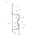
- FIG. 13 is a cross-sectional view taken along line 16-16 in FIG.
- FIG. 19 is a cross-sectional view taken along line 17-17 in FIG.
- FIG. 19 is a cross-sectional view taken along line 18-18 in FIG.
- FIG. 13 is a cross-sectional view taken along line 16-16 in FIG.
- FIG. 19 is a cross-sectional view taken along line 17-17 in FIG.
- FIG. 19 is a cross-sectional view taken along line 18-18
- FIG. 12 is a perspective view of a front side frame and a reinforcing member shown in FIG. 11.
- FIG. 20 is a side view showing an easily deformable portion of the front side frame as seen from the vehicle body center shown in FIG. 19.
- FIG. 21 is a cross-sectional view taken along line 21-21 in FIG.
- FIG. 22 is a cross-sectional view taken along line 22-22 of FIG.
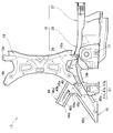
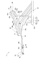
- the vehicle body front structure includes a front bulkhead 15 provided in front of the vehicle body 11, and a front side frame extending from the front bulkhead 15 in the rearward direction of the vehicle body.
- a damper house 17 provided in the middle of the front side frame 16 and outside the vehicle width
- a sub frame (front sub frame) 18 supported by the front side frame 16
- a rear portion of the front side frame 16 Dashboard lower panel 21 (FIG. 4) that partitions engine room 13 and vehicle compartment 12, floor panel 22 (FIG. 4) provided behind dashboard lower panel 21, and rear panel and floor panel of dashboard lower panel 21.
- Side sill 23 extending in the longitudinal direction of the vehicle body on the side of 22
- a tunnel portion 24 extending in the longitudinal direction of the vehicle body at the rear and the vehicle width direction central Gerhard board lower panel 21.
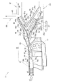
- the front side frame 16 includes a straight portion 27 whose front portion extends linearly in the vehicle longitudinal direction, a curved portion 28 whose middle portion is curved in the vehicle width direction, and a rear portion linearly downward toward the rear of the vehicle body. And an inclined bent portion (kick-down portion) 29 (see FIG. 15).
- the front side frame 16 is a member having a rectangular closed section including a bottom portion 16 a, an inner wall 16 b, an outer wall 16 c, and a ceiling portion 16 d.
- a front frame side bead 74 is formed along the bead 65 of the reinforcing member 35 on the inner wall 16 b of the front side frame 16.
- the subframe 18 is coupled by a load path member 25 that transmits a load to the front bulkhead 15. Thereby, smooth load transmission is possible when a front collision load is applied from the front of the vehicle body.
- the curved portion 28 has three recesses (which allow the front side frame 16 to be bent when the front side load is applied to the front side frame 16 from the front of the vehicle body and to allow the front side frame 16 to be bent.
- First to third recesses) 31 to 33 are formed.
- the first recess 31 is a recess that allows the inner bending of the front side frame 16.
- the second recess (easy-to-deform portion) 32 (FIG. 22) is a recess that allows the outer bending of the front side frame 16 as will be described later.
- the third recess 33 is a recess that allows the inner bending of the front side frame 16.
- a reinforcing member (internal stiffener) 35 which will be described later, is provided between the first to third recesses 31-33. Between the first recess 31 and the second recess 32, a first nut member 38 and a second nut member 39 for supporting the power component 19 (FIG. 1) are provided.
- the power component 19 is an engine, a mission, or the like.
- the first nut member 38 is connected to the outer wall 16c (FIG. 2) of the front side frame 16 via the first bulkhead 41 and the front side frame 16 via the reinforcing member 35. It is supported by the inner wall 16b (FIG. 2).
- the second nut member 39 is supported by the inner wall 16b via the outer wall 16c and the reinforcing member 35 via the second bulkhead 42.
- the support portions of the first and second nut members 38 and 39 are reinforced by the reinforcing member 35, and the first and second bulkheads 41 and 42 are respectively passed into the front side frame 16 to be Since the inside of the frame 16 is partitioned, the support strength of the first and second nut members 38 and 39 can be improved. As a result, it is possible to firmly support a heavy power component (engine or transmission) 19 (FIG. 1).
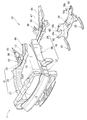
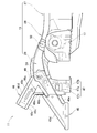
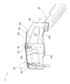
- a bent portion 29 is provided at the rear portion of the front side frame 16.
- the side sill side extension 45 that bends toward the side sill 23 from the rear end 29 a (FIG. 8) of the bent portion 29, and the tunnel portion 24 (FIG. 4) from the rear end 29 a of the bent portion 29.
- the tunnel side extension 46 that bends is branched.
- the bent portion 29 is inclined downward toward the rear of the vehicle body along the dashboard lower panel 21 (FIG. 4), and the rear end 29a is extended horizontally.
- the bent portion 29, which is the rear portion of the front side frame 16, is provided with a side sill side extension 45 (FIG. 4) bent toward the side sill 23, and is branched at substantially the same angle as the side sill side extension 45.
- a tunnel-side extension 46 (FIG. 4) is provided that is directed to the (FIG. 4) side.
- an extension line extending in the longitudinal direction of the vehicle body passing through a rear end support portion 59 of a branching portion 48 to be described later is extended along the longitudinal direction of the side sill side extension portion 45.
- the extension line along the longitudinal direction of the tunnel side extension 46 is C3
- the angle between the extension line C1 and the extension line C2 is ⁇ 1
- the angle between the extension line C1 and the extension line C3 is ⁇ 2.
- the angle ⁇ 1 and the angle ⁇ 2 are formed at substantially the same angle.
- the angles ⁇ 1 and ⁇ 2 are preferably 30 ° ⁇ 10 ° in consideration of load transmission efficiency.
- the branch part 48 is a part where the side sill side extension part 45 begins to bend, and is a bent part.
- a stiffener (reinforcing member) 36 is provided from the bent portion 29 to the branch portion 48.
- the stiffener 36 suppresses bending of the bent portion 29 when a frontal impact load is applied to the front side frame 16 from the front of the vehicle body 11, and a side impact load is applied to the front side frame 16 from the side of the vehicle body 11.
- the side impact load is transmitted to the outrigger 47 and the tunnel side extension 46.
- the stiffener 36 is disposed so as to face a reinforcing member 35 described later.
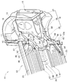
- the stiffener 36 has a bottom surface 36a (FIGS. 2 and 9) facing the bottom portion 16a of the bent portion 29 (front side frame 16), and a stiffener inner wall 36b raised from the bottom surface 36a.
- the stiffener outer wall 36c and flanges 36d and 36e provided on the inner wall 36b and the outer wall 36c, respectively.
- the stiffener 36 extends on the bottom surface 36a (FIG. 12) in the vehicle width direction and is connected to a rear wall 47c of an outrigger 47 described later and a rear wall 49a (FIG. 12) of a load support portion 49 (FIG. 14). And a bead (raised bead) 52 extending in the longitudinal direction in the center of the bottom surface 36a, and a support hole 53 for supporting a collar nut 63 described later. As shown in FIGS. 12, 13, and 16, the step portion 51 is formed with an upper ridge line 54 and a lower ridge line 55 that contribute to the transmission of the side collision load.
- the stiffener 36 is coupled (spot welded) to the bottom portion 16a of the bent portion 29 (front side frame 16), the inner wall 16b (FIG. 2), and the outer wall 16c at the front portion 71 (FIG. 9) of the stiffener 36.
- the flanges 36d and 36e of the stiffener 36 are coupled to the flanges 46d and 46e of the tunnel side extension 46 via the flanges 45d and 45e of the side sill side extension 45.
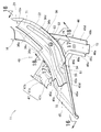
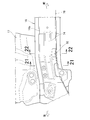
- a portion where the bent portion 29, the side sill side extension 45 and the tunnel side extension 46 intersect is a branching portion 48 where the side sill side extension 45 and the tunnel side extension 46 are branched. is there. From the branch portion 48, the outrigger 47 extends outward in the vehicle width direction, and the outrigger 47 is coupled to the side sill 23 (FIG. 4).
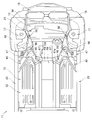
- the bent part 29, the side sill side extension part 45, the tunnel side extension part 46, and the branch part 48 of the front side frame 16 are formed to have substantially the same width in the rear view.
- the total depth of the side sill side extension 45 and the subframe mount bracket 61 is formed as d1, and the depth of the tunnel side extension 46 is formed as d2, and the outriggers are formed.
- the depth 47 is formed as d3.
- the total depth of the side sill side extension 45 and the subframe mount bracket 61 is expressed as e1
- the depth of the tunnel side extension 46 is expressed as e2.
- branch portion 48 is formed with a deeper (higher) cross section than the bent portion 29, the outrigger 47, the side sill side extension portion 45, and the tunnel side extension portion 46 of the front side frame 16.
- the cross-sectional area around the branch portion 48 is set larger than the cross-sectional areas of the bent portion 29, the side sill side extension portion 45, and the tunnel side extension portion 46 of the front side frame 16.
- the cross-sectional depth of each frame is increased to improve strength and rigidity.
- the side sill side extension 45 is provided integrally with the bent portion 29 of the front side frame 16, and from the rear end 29 a (FIG. 8) of the bent portion 29.
- the side sill 23 extends obliquely and is coupled to the side sill 23 behind the outrigger 47 (see FIG. 5).
- the side sill-side extension 45 is a U-shaped member in cross-section, and includes a bottom 45a, an inner wall 45b raised from the bottom 45a, an outer wall 45c raised from the bottom 45a, and an inner wall 45b.
- the inner flange 45d is provided, and the outer flange 45e is provided on the outer wall 45c.
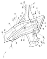
- a site where the tunnel side extension 46 is coupled to the side sill side extension 45 is referred to as an inner wall side coupling portion 75.
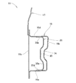
- the tunnel-side extension 46 includes a bottom 46a, an inner wall 46b raised from the bottom 46a, a rear wall 49a provided continuously in the vehicle width direction with the inner wall 46b, and an outer wall 46c raised from the bottom 46a.
- the inner flange 46d is provided on the inner wall 46b
- the flange 49b is continuously provided on the outer flange 46e
- the outer flange 46e is provided on the outer wall 46c.
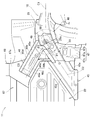
- a triangular load support portion (load receiving portion) 49 is provided at the rear side of the branching portion 48, and extends to the side sill side extension portion 45 and the tunnel side extension portion 46.
- the load support portion 49 is formed integrally with the tunnel side extension portion 46, and is a portion constituted by a part of the bottom portion 46a of the tunnel side extension portion 46, a rear wall 49a, and a rear flange 49b.
- the rear wall 49a extends in the vehicle width direction and is formed substantially perpendicular to the vehicle body height direction.
- the part of the bottom 46 a of the tunnel side extension 46 refers to a triangular region in which the bottom 46 a of the tunnel side extension 46 is extended to the side sill side extension 45.
- the front impact load acting from the front of the vehicle body as indicated by the arrow a1 is linearly applied from the inner wall 16b of the front side frame 16 to the outer wall 16c of the front side frame 16 via the reinforcing member 35 as indicated by the arrow a2. Is transmitted to.
- This linearly transmitted load is branched at the branching portion 48 and transmitted to the side sill 23 via the side sill side extension 45 and the stiffener 36 as indicated by an arrow a3, and the stiffener 36 and the tunnel side extension as indicated by an arrow a4. It is transmitted to the tunnel frame 67 via the portion 46 and also transmitted to the side sill 23 and the tunnel frame 67 on the other side via the tunnel cross member 68 as indicated by an arrow a5.
- the reinforcing member 35 extends from the inner wall 16b of the front side frame 16 as indicated by an arrow a2. Is easily transmitted linearly to the outer wall 16c of the front side frame 16 (FIGS. 9 to 11).
- the side impact load acting from the side of the vehicle body as indicated by the arrow b1 is transmitted from the side sill 23 to the rear wall 47c of the outrigger 47 as indicated by the arrow b2, and the load support portion 49 (FIG. 6). It is transmitted to the tunnel side extension 46 through the rear wall 49a as shown by the arrow b3, and through the tunnel cross member 68 as shown by the arrow b4, and then through the other load support part 49, the outrigger 47 and the side sill 23 as shown by the arrow b5. And the transmission load can be distributed to the other side sill side extension 45 as shown by the arrow b6.
- the side sill side extension portion 45 is reinforced by a stiffener 36 and can transmit a large load to the side sill 23 having high strength, and the tunnel side extension portion 46 is a frame having a lower strength than the side sill side extension portion 45.
- the front impact load can be transmitted mainly to the high-strength side sill 23, thereby making it possible to reduce the weight of the vehicle body 11 by reducing or eliminating the tunnel frame 67 of the tunnel portion 24. is there.
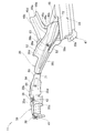
- a subframe mount bracket 61 that supports the subframe 18 is provided at the branch portion 48.
- the sub-frame mount bracket 61 and the stiffener 36 support the top and bottom of the collar nut 63 (FIG. 18) to which the sub-frame 18 side fastening member 62 (FIG. 1) is coupled.
- the subframe mount bracket 61 supports the bottom of the collar nut 63
- the stiffener 36 supports the top of the collar nut 63.
- a rear end support portion 59 (FIG. 8) for supporting the rear end 18b of the subframe 18 is formed by the subframe mount bracket 61, the stiffener 36, and the collar nut 63.
- the front side frame 16 is formed with a front end support 58 (FIG. 5) that supports the front end 18 a of the subframe 18 in front of the rear end support 59. That is, the rear end support portion 59 that supports the rear end 18b (FIG. 1) of the subframe 18 is provided at the front and bent portion 29 of the load support portion 49 (FIGS. 6 and 8).
- the bending portion 28 is provided with a reinforcing member 35 extending from the front to the rear of the bending portion 28.
- the reinforcing member 35 is coupled to the inner wall 16b of the curved portion 28 (front side frame 16) from the front to the middle of the curved portion 28, and coupled to the outer wall 16c of the curved portion 28 behind the curved portion 28.
- Bulkheads (first and second bulkheads) 41 and 42 for fixing nut members (first and second nut members) 38 and 39 for supporting the power component 19 (FIG. 1) are coupled to each other. .
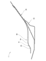
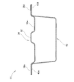
- the reinforcing member 35 has a U-shaped cross section, a bottom wall 64 extending in the longitudinal direction of the vehicle body, and a first upper flange bent substantially horizontally from the top of the bottom wall 64. 35a and a second upper flange 35b, and a first lower flange 35c and a second lower flange 35d bent substantially horizontally from the lower part of the bottom wall 64.
- a bead 65 is formed on the bottom wall 64 having a U-shaped cross section along the longitudinal direction of the vehicle body.
- the energy absorption amount is improved by allowing the front side frame 16 to be bent behind the bulkhead 42 and on the inner wall 16 b of the curved portion 28 (front side frame 16).
- An easily deformable portion 32 (FIG. 3) is provided. In a portion corresponding to the easily deformable portion 32, a flange is not formed on the reinforcing member 35 having a U-shaped cross section. Therefore, the first and second upper flanges 35a and 35b are divided and formed, and the first and second lower flanges 35c and 35d are divided and formed.
- the easily deformable portion 32 is recessed by a dimension t1 at the maximum from the cross section of the easily deformable portion 32 on the rear side of the vehicle body.
- the easily deformable portion 32 is more likely to concentrate the load than the front and rear portions of the easily deformable portion 32.
- the ridge line 76 is locally bent, and stress is concentrated on the recess (easy deformable portion) 32. be able to. Further, since only the shape of one ridge line 76 is deformed, the change in the cross-sectional area of the front side frame 16 is small. Accordingly, there is no decrease in the overall strength of the front side frame 16.
- the easy-to-deform portion 32 is a portion that allows the front side frame 16 to be mountain-folded outside the vehicle width on the side away from the power component 19 (see FIG. 1).
- the easily deformable portion 32 is a recess (second recess 32) provided on the inner wall 16b where the cross-sectional width of the front side frame 16 is reduced in plan view.
- the easily deformable portion 32 is formed at a position where the reinforcing member 35 having a U-shaped cross section is interrupted.
- the outrigger 47 is a member extending along the vehicle width direction.
- the outrigger 47 includes an outrigger bottom portion 47a along the floor panel 22, and a front wall 47b and a rear wall 47c raised from the bottom portion 47a in the vehicle body height direction.
- the outrigger 47 extends in the vehicle width direction from the vicinity of the rear portion (bent portion 29) of the front side frame 16 and is coupled to the front end 23 a of the side sill 23.
- the tunnel portion 24 includes a center tunnel 66 in which the center portion of the floor panel 22 is raised toward the vehicle compartment 12 side, and 2 extending in the longitudinal direction of the vehicle body on the left and right sides of the center tunnel 66.
- a tunnel frame 67 and a tunnel cross member 68 spanned between the front ends 67 a of the tunnel frame 67 or the rear ends 73 (FIG. 10) of the tunnel side extension 46.
- the tunnel cross member 68 is formed along the convex shape of the raised center tunnel 66.
- a front side frame 16 extending in the longitudinal direction of the vehicle body and a rear portion of the front side frame 16 are provided.
- the dashboard lower panel 21 that divides the vehicle body 12, the subframe 18 supported by the front side frame 16, the side sill 23 that extends in the vehicle longitudinal direction on the side of the floor panel 22, and the vehicle body from the dashboard lower panel 21 to the floor panel 22.
- a tunnel portion 24 extending in the front-rear direction of the vehicle body at the center, and the rear portion of the front side frame 16 is inclined downwardly toward the rear of the vehicle body along the dashboard lower panel 21 and is extended horizontally.
- a bent portion 29, and a rear end 29a of the bent portion 29 has a side cross-section with a continuous closed cross section.
- a side sill side extension 45 bent to the side 23 and a tunnel side extension 46 bent from the inner wall 45b of the closed cross section toward the tunnel part 24 are branched at substantially the same angle so as to constitute the branch part 48. Therefore, the load from the front side frame 16 at the time of the front collision can be transmitted preferentially to the high side sill 23 using, for example, a high-strength steel plate, and the reinforcement below the floor panel 22 can be reduced. It becomes possible.
- a triangular load support portion 49 is formed at the rear side of the branch portion 48 and extends to the side sill side extension portion 45 and the tunnel side extension portion 46. Since the rear end support portion 59 for supporting the rear end 18b of the subframe 18 is provided at the front and bent portion 29 of the portion 49, the front support load is received by the load support portion 49 of the branch portion 48, and the side sill side extension portion 45 and The direction change to the tunnel side extension 46 can be promoted and the load can be transmitted in the respective axial directions.
- the subframe 18 can be firmly supported.
- the front impact load is applied to the front side frame 16 from the front of the vehicle body, the front impact load is received by the branching portion 48 and the load support portion 49, and a reaction force is generated on the sub frame 18 so that the sub frame 18 is sufficiently
- the amount of energy absorption of the front side frame 16 can be increased by buckling.
- the reaction force is concentrated on the rear end support portion 59, the fastening member (fastening bolt) 62 is broken or pulled out from the vehicle body 11, and the subframe 18 is dropped to remove the front side frame 16.
- a subframe mounting bracket 61 that supports the subframe 18 is provided at the branching portion 48, and extends from the bent portion 29 to the branching portion 48.
- a front impact load is applied to the front side frame 16 from the front of the vehicle body 11
- the bending of the bent portion 29 is suppressed
- a side impact load is applied to the front side frame 16 from the side of the vehicle body 11.
- a stiffener 36 for transmitting the side impact load to the tunnel side extension 46 is provided.
- the sub-frame mounting bracket 61 and the stiffener 36 support the upper and lower sides of the collar nut 63 to which the fastening member 62 on the sub-frame 18 side is coupled. It is possible to evenly distribute the load from the front side frame 16 to the side sill 23 and the tunnel portion 24 through the stiffener 36.
- the front portion 71 of the stiffener 36 is coupled to the bottom portion 16a of the bent portion 29 (front side frame 16), and the rear portion 72 is interposed via flanges 45d and 45e of the side sill side extension portion 45.
- the load from the front side frame 16 and the sub frame 18 can be easily distributed to the side sill side extension 45 and the tunnel side extension 46.
- the longitudinal bead 52 is provided at the center of the stiffener 36, it is possible to prevent the bent portion 29 of the front side frame 16 from being bent and the front side frame 16.
- the load can be distributed in the front-rear direction.
- the outrigger 47 extending outward in the vehicle width direction from the branch portion 48 is coupled to the side sill 23, so that when a side impact load is applied from the side of the vehicle body 11, the side impact The load can be distributed from the side sill 23 to the branch portion 48 via the outrigger 47. Furthermore, since the outrigger 47 extending outward in the vehicle width direction from the branch portion 48 is coupled to the side sill 23, the support strength of the subframe 18 can be increased.
- the cross-sectional area around the branch portion 48 is set to be larger than the cross-sectional areas of the bent portion 29, the side sill side extension portion 45, and the tunnel side extension portion 46 of the front side frame 16. Therefore, the load support strength of the branch part 48 can be increased. As a result, when a front collision load from the front of the vehicle body acts on the front side frame 16, it is possible to suppress the bending of the rear bent portion (kick down portion) 29 of the front side frame 16.
- the front side frame 16 has a curved portion 28 that is curved from the front to the rear in the vehicle body front-rear direction and from the outside to the inside in the vehicle width direction. Since the reinforcing member 35 is provided from the rear to the rear and the stiffener 36 is disposed so as to face the reinforcing member 35, the bending portion 28 is bent by the front impact load when the front impact load is applied from the front of the vehicle body. The front collision load can be transmitted to the side sill 23 while being suppressed. Thereby, the load transmission efficiency of the front side frame 16 can be improved.
- the present embodiment an example is shown in which the rear portion of the reinforcing member 35 is disposed so as to face the front portion 71 of the stiffener 36, but the present invention is not limited thereto, and the reinforcing member 35 and the stiffener are not limited thereto. 36 may be directly coupled.
- a front side frame 16 extending in the longitudinal direction of the vehicle body and a rear portion of the front side frame 16 are provided.
- a dashboard lower panel 21 that divides the chamber 12 a floor panel 22 provided behind the dashboard lower panel 21, a side sill 23 that extends laterally of the vehicle body at the side of the floor panel 22, and a floor panel from the dashboard lower panel 21. 22 is provided with a tunnel portion 24 extending in the longitudinal direction of the vehicle body at the center of the vehicle body.
- the rear portion of the front side frame 16 is inclined downwardly toward the rear of the vehicle body along the dashboard lower panel 21, and the rear end 29a (FIG. 7) is horizontal.
- An extended bent portion (kick down portion) 29 is provided.
- a side sill side extension portion 45 bent toward the side sill 23 and a tunnel side extension portion 46 bent from the bent portion toward the tunnel portion 24 have substantially the same angle.
- a branching portion 48 (FIG. 8) branched off at is provided.
- a stiffener 36 is provided that transmits the side impact load to the outrigger 47 and the tunnel side extension 46 when a side impact load is applied. Thereby, it is possible to suppress the bending of the rear portion of the front side frame 16 due to the front impact load, and to transmit the side impact load to the outrigger 47 and the tunnel side extension portion 46, and for example, to the tunnel portion 24, the tunnel frame 67 (FIG. 4). ) And the tunnel cross member 68 (FIG. 4) can be distributed and transmitted to the tunnel frame 67 and the tunnel cross member 68.
- the vehicle body front part structure has a triangular load support portion 49 that extends to the side sill side extension portion 45 and the tunnel side extension portion 46 behind the branch portion 48.
- the front impact load can be distributed and transmitted to the tunnel portion 24 (tunnel frame 67 and tunnel cross member 68) via the load support portion 49 of
- the stiffener 36 has a step portion 51 connected to the rear wall 47c of the outrigger 47 and the rear wall 49a of the load support portion 49. Therefore, the stepped portion 51 connected to the rear wall 47c of the outrigger 47 and the rear wall 49a of the load support portion 49 enables further distributed transmission to the tunnel portion 24 (tunnel frame 67 and tunnel cross member 68) shown in FIG. Become.
- the tunnel portion 24 includes a center tunnel 66 in which the center portion of the floor panel 22 (FIG. 4) rises toward the passenger compartment 12, and the vehicle body longitudinally on the left and right sides of the center tunnel 66.
- the tunnel frame 67 is extended, and the tunnel cross member 68 is passed between the front ends 67a of the tunnel frame 67 or between the rear ends 73 of the tunnel side extensions 46.
- the tunnel cross member 68 is provided between the front ends 67a of the tunnel frame 67 or between the rear ends 73 of the tunnel side extensions 46, the load from the tunnel side extension 46 is applied to the vehicle body 11 from one side of the vehicle body 11. Distributed transmission can also be performed on the other side.
- the front portion 71 of the stiffener 36 is coupled to the bottom portion 16a of the bent portion 29 (front side frame 16), and the rear portion 72 is tunneled through flanges 45d and 45e of the side sill side extension portion 45. Since it is connected to the flanges 46 d and 46 e of the side extension 46, the load from the front side frame 16 is easily dispersed to the side sill side extension 45 and the tunnel side extension 46.
- the vehicle body front structure has a bead 52 in the longitudinal direction at the center of the stiffener 36, so that the bent portion 29 of the front side frame 16 can be prevented from being bent and the front side frame 16 can be prevented from bending.
- the load can be distributed in the front-rear direction.
- the outrigger 47 extending outward in the vehicle width direction from the branch portion 48 is coupled to the side sill 23, so that a side impact load acts from the side of the vehicle body 11.
- the side impact load can be distributed from the side sill 23 to the branch portion 48 via the outrigger 47.
- the outrigger 47 extending outward in the vehicle width direction from the branch portion 48 is coupled to the side sill 23, the support strength of the front side frame 16 can be increased.
- the cross-sectional area around the branch portion 48 is set to be larger than the cross-sectional areas of the bent portion 29, the side sill side extension portion 45, and the tunnel side extension portion 46 of the front side frame 16. Therefore, the load support strength of the branch part 48 can be increased. Therefore, when a frontal collision load from the front of the vehicle body acts on the front side frame 16, it is possible to suppress the bending of the rear bent portion (kick down portion) 29 of the front side frame 16.
- the front side frame 16 has a curved portion 28 that is curved inward from the outside in the vehicle width direction from the front to the rear, and the curved portion 28 is the curved portion 28. Since the stiffener 36 is disposed so as to face the reinforcing member 35, when the front impact load is applied from the front of the vehicle body, the bending due to the front impact load is provided. The front collision load can be transmitted to the side sill 23 while suppressing the bending of the portion 28. Thereby, the load transmission efficiency of the front side frame 16 can be improved.
- the vehicle body front structure according to the present invention is suitable for use in passenger cars such as sedans and wagons, particularly small cars.
- SYMBOLS 11 Vehicle body, 12 ... Car compartment, 13 ... Engine room, 16 ... Front side frame, 16a ... Bottom part, 16b ... Inner wall, 16c ... Outer wall, 18 ... Sub-frame, 18b ... Rear end, 21 ... Dashboard lower panel, 22 ... Floor panel, 23 ... side sill, 24 ... tunnel part, 28 ... curved part, 29 ... bent part, 29a ... rear end of bent part, 35 ... reinforcing member, 36 ... stiffener, 45 ... side sill side extension part, 45d, 45e ... Side sill side extension, 46 ... Tunnel side extension, 46d, 46e ... Tunnel side extension (inside and outside) flange, 47 ...
Abstract
Description
Claims (16)
- 車体前部構造であって、
車体前後方向に延びるフロントサイドフレームと、
前記フロントサイドフレームの後部に設けられ、エンジンルームと車室とを仕切るダッシュボードロアパネルと、
前記フロントサイドフレームに支持されるサブフレームと、
前記ダッシュボードロアパネルの後方に設けられたフロアパネルの側方にて車体前後方向に延びているサイドシルと、
前記ダッシュボードロアパネルから前記フロアパネルに車幅方向中央にて車体前後方向に延びるトンネル部と、
を具備しており、
前記フロントサイドフレームは、その後部に、前記ダッシュボードロアパネルに沿って車体後方に向かうに連れて下方に傾斜するよう延びている折れ曲がり部を有し、
前記折れ曲がり部の後部は、前記サイドシル側に屈曲するサイドシル側延長部と、前記トンネル部に向けて屈曲するトンネル側延長部と、を実質上同一角度で分岐された分岐部を有し、
前記分岐部の後方にて前記サイドシル側延長部および前記トンネル側延長部間に三角形状の荷重支持部が形成され、前記荷重支持部の前方且つ前記折れ曲がり部に、前記サブフレームの後端を支持する後端支持部が設けられていることを特徴とする車体前部構造。 - 前記分岐部は、前記サブフレームを支持するサブフレームマウントブラケットを備え、
前記フロントサイドフレームに車体の前方から前突荷重が作用したときには、前記折れ曲がり部の折れ曲がりを抑制し、前記フロントサイドフレームに車体の側方から側突荷重が作用したときには、前記側突荷重を前記トンネル側延長部に伝達するスチフナが、前記折れ曲がり部から前記分岐部に亘って設けられており、
前記サブフレーム側の締結部材が結合されるカラーナットの上下が、前記サブフレームマウントブラケットと前記スチフナとで支持される、請求項1に記載の車体前部構造。 - 前記スチフナは、前記折れ曲がり部の底部に結合される前部と、前記サイドシル側延長部のフランジを介して前記トンネル側延長部のフランジに結合される後部とを有する、請求項2に記載の車体前部構造。
- 前記スチフナは、該スチフナの中央に長手方向のビードを有する、請求項2に記載の車体前部構造。
- 前記サイドシルは、前記分岐部から車幅方向外側に延びたアウトリガに結合されている、請求項1に記載の車体前部構造。
- 前記分岐部は、前記フロントサイドフレームの折れ曲がり部、前記サイドシル側延長部および前記トンネル側延長部の断面積よりも大きく設定された前記分岐部の周辺の断面積を有する、請求項1に記載の車体前部構造。
- 前記フロントサイドフレームは、車幅方向の外側から内側に向けて湾曲した湾曲部を備え、前記湾曲部は、該湾曲部の前方から後方に亘り設けられた補強部材を備え、前記スチフナは、前記補強部材に対峙して配置されている、請求項2に記載の車体前部構造。
- 前記分岐部は、車幅方向外側に延びるよう設けられたアウトリガを備え、前記フロントサイドフレームに車体の前方から前突荷重が作用したときに、前記折れ曲がり部の折れ曲がりを抑制し、前記フロントサイドフレームに車体の側方から側突荷重が作用したときに、該側突荷重を前記アウトリガ及び前記トンネル側延長部に伝達するスチフナが、前記折れ曲がり部から前記分岐部に亘って設けられている、請求項1に記載の車体前部構造。
- 前記分岐部は、その後方に、前記サイドシル側延長部及び前記トンネル側延長部に間に形成された三角形状の前記荷重支持部を有する、請求項8に記載の車体前部構造。
- 前記スチフナは、前記アウトリガの後壁と前記荷重支持部の後壁とに繋がる段部を有する、請求項8に記載の車体前部構造。
- 前記トンネル部は、前記フロアパネルの中央部が前記車室側に隆起されるセンタトンネルと、前記センタトンネルの左右にて車体前後方向に延びたトンネルフレームと、トンネルフレームの前端同士若しくは前記トンネル側延長部の後端同士に渡されたトンネルクロスメンバとからなる、請求項8に記載の車体前部構造。
- 前記スチフナは、前部が前記折れ曲がり部の底部に結合され、後部が前記サイドシル側延長部のフランジを介して前記トンネル側延長部のフランジに結合されている、請求項8に記載の車体前部構造。
- 前記スチフナは、前記スチフナの中央に長手方向のビードを有する、請求項8に記載の車体前部構造。
- 前記サイドシルは、前記分岐部から車幅方向外側に延びたアウトリガに結合されている、請求項8に記載の車体前部構造。
- 前記分岐部は、前記フロントサイドフレームの折れ曲がり部、前記サイドシル側延長部およびトンネル側延長部の断面積よりも大きく設定された前記分岐部の周辺の断面積を有する、請求項8に記載の車体前部構造。
- 前記フロントサイドフレームは、車幅方向の外側から内側に向けて湾曲した湾曲部を備え、前記湾曲部は、該湾曲部の前方から後方に亘り設けられた補強部材を備え、前記スチフナは、前記補強部材に対峙して配置されている、請求項8に記載の車体前部構造。
Priority Applications (6)
| Application Number | Priority Date | Filing Date | Title |
|---|---|---|---|
| US13/981,399 US8794696B2 (en) | 2011-01-26 | 2012-01-10 | Structure for front of vehicle body |
| MX2013008240A MX357922B (es) | 2011-01-26 | 2012-01-10 | Estructura para el frente de carroceria de vehiculo. |
| BR112013018424A BR112013018424A2 (pt) | 2011-01-26 | 2012-01-10 | estrutura para frente de carroceria de veículo |
| EP12738751.2A EP2669151B1 (en) | 2011-01-26 | 2012-01-10 | Structure for front of vehicle body |
| JP2012554707A JP5557929B2 (ja) | 2011-01-26 | 2012-01-10 | 車体前部構造 |
| CN201280006546.7A CN103339019B (zh) | 2011-01-26 | 2012-01-10 | 车身前部结构 |
Applications Claiming Priority (4)
| Application Number | Priority Date | Filing Date | Title |
|---|---|---|---|
| JP2011014047 | 2011-01-26 | ||
| JP2011-014071 | 2011-01-26 | ||
| JP2011014071 | 2011-01-26 | ||
| JP2011-014047 | 2011-06-21 |
Publications (1)
| Publication Number | Publication Date |
|---|---|
| WO2012102067A1 true WO2012102067A1 (ja) | 2012-08-02 |
Family
ID=46580640
Family Applications (1)
| Application Number | Title | Priority Date | Filing Date |
|---|---|---|---|
| PCT/JP2012/050231 WO2012102067A1 (ja) | 2011-01-26 | 2012-01-10 | 車体前部構造 |
Country Status (7)
| Country | Link |
|---|---|
| US (1) | US8794696B2 (ja) |
| EP (1) | EP2669151B1 (ja) |
| JP (1) | JP5557929B2 (ja) |
| CN (1) | CN103339019B (ja) |
| BR (1) | BR112013018424A2 (ja) |
| MX (1) | MX357922B (ja) |
| WO (1) | WO2012102067A1 (ja) |
Cited By (6)
| Publication number | Priority date | Publication date | Assignee | Title |
|---|---|---|---|---|
| KR101620694B1 (ko) * | 2013-07-09 | 2016-05-12 | 도요타 지도샤(주) | 차체 전부 구조 |
| JP2017074877A (ja) * | 2015-10-15 | 2017-04-20 | 本田技研工業株式会社 | 衝撃吸収部材付き車体構造 |
| EP3018041A4 (en) * | 2013-07-02 | 2017-06-07 | Nissan Motor Co., Ltd | Vehicle body front section structure |
| JP2019023052A (ja) * | 2017-07-25 | 2019-02-14 | トヨタ自動車株式会社 | 車体前部構造 |
| JP2019127163A (ja) * | 2018-01-25 | 2019-08-01 | 本田技研工業株式会社 | 車体構造 |
| JP2020111243A (ja) * | 2019-01-15 | 2020-07-27 | スズキ株式会社 | 車体下部構造 |
Families Citing this family (12)
| Publication number | Priority date | Publication date | Assignee | Title |
|---|---|---|---|---|
| JP6057171B2 (ja) | 2013-03-01 | 2017-01-11 | スズキ株式会社 | サスペンションフレームの構造 |
| KR101637287B1 (ko) * | 2014-09-02 | 2016-07-07 | 현대자동차 주식회사 | 서브 프레임용 마운팅 유닛 |
| DE102015106272A1 (de) * | 2015-04-23 | 2016-10-27 | Dr. Ing. H.C. F. Porsche Aktiengesellschaft | Bodenstruktur eines Kraftfahrzeugs |
| DE102016203673A1 (de) * | 2016-03-07 | 2017-09-21 | Volkswagen Aktiengesellschaft | Karosserie-Bodenstruktur für ein Fahrzeug |
| US9889892B2 (en) * | 2016-07-18 | 2018-02-13 | GM Global Technology Operations LLC | Attachment bulkhead for body structures |
| KR101855781B1 (ko) * | 2016-11-02 | 2018-05-09 | 현대자동차 주식회사 | 전방 차체 보강구조 |
| JP6819476B2 (ja) * | 2017-06-16 | 2021-01-27 | トヨタ自動車株式会社 | 車両前部構造 |
| CN107600194B (zh) * | 2017-08-25 | 2019-09-17 | 吉利汽车研究院(宁波)有限公司 | 一种汽车地板加强结构及汽车 |
| US10807650B2 (en) * | 2017-10-11 | 2020-10-20 | Ford Global Technologies, Llc | Hood latch support beam |
| JP6763902B2 (ja) * | 2018-03-27 | 2020-09-30 | 株式会社豊田自動織機 | ワイパー用マウントブラケット |
| JP7238004B2 (ja) * | 2021-03-17 | 2023-03-13 | 本田技研工業株式会社 | 車体前部構造 |
| CN115158463B (zh) * | 2022-07-26 | 2023-09-22 | 东风柳州汽车有限公司 | 一种汽车底盘 |
Citations (5)
| Publication number | Priority date | Publication date | Assignee | Title |
|---|---|---|---|---|
| JPH05270435A (ja) * | 1992-03-27 | 1993-10-19 | Nissan Shatai Co Ltd | 車体フロアメンバ構造 |
| JPH06219333A (ja) * | 1993-01-26 | 1994-08-09 | Nissan Motor Co Ltd | 車両のサスペンション取付部構造 |
| JP2001219873A (ja) * | 2000-02-10 | 2001-08-14 | Toyota Auto Body Co Ltd | 車両の車体下部構造 |
| JP2009018724A (ja) * | 2007-07-12 | 2009-01-29 | Honda Motor Co Ltd | 車体フレーム構造 |
| JP4325351B2 (ja) | 2003-10-08 | 2009-09-02 | 三菱自動車工業株式会社 | 車両のシャシ取付構造 |
Family Cites Families (15)
| Publication number | Priority date | Publication date | Assignee | Title |
|---|---|---|---|---|
| KR930003119B1 (ko) | 1991-03-12 | 1993-04-19 | 정태근 | 자동차의 안전벨트 자동착용장치 |
| JP3995315B2 (ja) * | 1997-09-16 | 2007-10-24 | 富士重工業株式会社 | 車両の前部車体構造 |
| DE60207015T2 (de) * | 2001-07-31 | 2006-08-03 | Nissan Motor Co., Ltd., Yokohama | Vorbaustruktur für ein Kraftfahrzeug |
| DE10309002A1 (de) * | 2003-03-01 | 2004-09-09 | Adam Opel Ag | Karosserie |
| JP4680784B2 (ja) * | 2006-01-17 | 2011-05-11 | 本田技研工業株式会社 | 自動車の前部車体構造 |
| JP4302151B2 (ja) * | 2007-04-20 | 2009-07-22 | 本田技研工業株式会社 | 車両用フロアパネル |
| JP4286884B2 (ja) * | 2007-06-28 | 2009-07-01 | 本田技研工業株式会社 | 自動車の車体構造 |
| TWI361766B (en) * | 2007-07-12 | 2012-04-11 | Honda Motor Co Ltd | Vehicle body frame structure |
| JP5063287B2 (ja) * | 2007-10-10 | 2012-10-31 | 本田技研工業株式会社 | 車体前部構造 |
| DE602008000209D1 (de) * | 2007-10-10 | 2009-11-26 | Honda Motor Co Ltd | Vorderteilkonstruktion einer Fahrzeugkarosserie |
| US7469957B1 (en) * | 2007-12-07 | 2008-12-30 | Honda Motor Co., Ltd. | Front floor frame |
| JP4653210B2 (ja) * | 2008-11-12 | 2011-03-16 | 本田技研工業株式会社 | 車体前部構造 |
| US8668248B2 (en) * | 2009-11-05 | 2014-03-11 | Honda Motor Co., Ltd. | Vehicle body structure |
| EP2514655A4 (en) * | 2009-12-16 | 2013-08-21 | Honda Motor Co Ltd | ASSEMBLY STRUCTURE OF VEHICLE BODY PANELS |
| GB2490392A (en) * | 2011-04-29 | 2012-10-31 | Gm Global Tech Operations Inc | Diagonally reinforced motor vehicle floor structure |
-
2012
- 2012-01-10 WO PCT/JP2012/050231 patent/WO2012102067A1/ja active Application Filing
- 2012-01-10 EP EP12738751.2A patent/EP2669151B1/en not_active Not-in-force
- 2012-01-10 JP JP2012554707A patent/JP5557929B2/ja active Active
- 2012-01-10 BR BR112013018424A patent/BR112013018424A2/pt not_active IP Right Cessation
- 2012-01-10 MX MX2013008240A patent/MX357922B/es active IP Right Grant
- 2012-01-10 CN CN201280006546.7A patent/CN103339019B/zh active Active
- 2012-01-10 US US13/981,399 patent/US8794696B2/en active Active
Patent Citations (5)
| Publication number | Priority date | Publication date | Assignee | Title |
|---|---|---|---|---|
| JPH05270435A (ja) * | 1992-03-27 | 1993-10-19 | Nissan Shatai Co Ltd | 車体フロアメンバ構造 |
| JPH06219333A (ja) * | 1993-01-26 | 1994-08-09 | Nissan Motor Co Ltd | 車両のサスペンション取付部構造 |
| JP2001219873A (ja) * | 2000-02-10 | 2001-08-14 | Toyota Auto Body Co Ltd | 車両の車体下部構造 |
| JP4325351B2 (ja) | 2003-10-08 | 2009-09-02 | 三菱自動車工業株式会社 | 車両のシャシ取付構造 |
| JP2009018724A (ja) * | 2007-07-12 | 2009-01-29 | Honda Motor Co Ltd | 車体フレーム構造 |
Non-Patent Citations (1)
| Title |
|---|
| See also references of EP2669151A4 |
Cited By (11)
| Publication number | Priority date | Publication date | Assignee | Title |
|---|---|---|---|---|
| EP3018041A4 (en) * | 2013-07-02 | 2017-06-07 | Nissan Motor Co., Ltd | Vehicle body front section structure |
| KR101620694B1 (ko) * | 2013-07-09 | 2016-05-12 | 도요타 지도샤(주) | 차체 전부 구조 |
| JP2017074877A (ja) * | 2015-10-15 | 2017-04-20 | 本田技研工業株式会社 | 衝撃吸収部材付き車体構造 |
| CN106585542A (zh) * | 2015-10-15 | 2017-04-26 | 本田技研工业株式会社 | 带冲击吸收部件的车身构造 |
| US9855971B2 (en) | 2015-10-15 | 2018-01-02 | Honda Motor Co., Ltd. | Vehicle body structure with impact absorbing part |
| CN106585542B (zh) * | 2015-10-15 | 2019-04-09 | 本田技研工业株式会社 | 带冲击吸收部件的车身构造 |
| JP2019023052A (ja) * | 2017-07-25 | 2019-02-14 | トヨタ自動車株式会社 | 車体前部構造 |
| JP2019127163A (ja) * | 2018-01-25 | 2019-08-01 | 本田技研工業株式会社 | 車体構造 |
| US10843733B2 (en) | 2018-01-25 | 2020-11-24 | Honda Motor Co., Ltd. | Vehicle body structure |
| JP2020111243A (ja) * | 2019-01-15 | 2020-07-27 | スズキ株式会社 | 車体下部構造 |
| JP7206931B2 (ja) | 2019-01-15 | 2023-01-18 | スズキ株式会社 | 車体下部構造 |
Also Published As
| Publication number | Publication date |
|---|---|
| MX2013008240A (es) | 2013-12-06 |
| BR112013018424A2 (pt) | 2016-10-11 |
| US8794696B2 (en) | 2014-08-05 |
| CN103339019A (zh) | 2013-10-02 |
| EP2669151A4 (en) | 2014-10-22 |
| MX357922B (es) | 2018-07-30 |
| JPWO2012102067A1 (ja) | 2014-06-30 |
| US20130334842A1 (en) | 2013-12-19 |
| CN103339019B (zh) | 2015-11-25 |
| JP5557929B2 (ja) | 2014-07-23 |
| EP2669151A1 (en) | 2013-12-04 |
| EP2669151B1 (en) | 2016-01-06 |
Similar Documents
| Publication | Publication Date | Title |
|---|---|---|
| JP5557929B2 (ja) | 車体前部構造 | |
| CN110352157B (zh) | 车辆的下部车身结构 | |
| JP5698340B2 (ja) | 車体後部構造 | |
| EP1808362B1 (en) | vehicle body | |
| JP6511078B2 (ja) | 電気自動車のフロア構造 | |
| JP6235628B2 (ja) | 自動車の車体構造 | |
| US8708390B2 (en) | Vehicle-body structure of vehicle and manufacturing method of the same | |
| JP4486996B2 (ja) | 車体構造 | |
| US20130249245A1 (en) | Front vehicle body structure | |
| JP5963060B2 (ja) | 車体後部のフロア構造 | |
| JP2009029244A (ja) | 車体構造 | |
| JP2013212757A (ja) | 車両の車体前部構造 | |
| JP2008230460A (ja) | 車両の下部車体構造 | |
| JP2018199471A (ja) | 車体前部構造 | |
| JP5320371B2 (ja) | 自動車の後部車体構造 | |
| JP4509533B2 (ja) | 車両用サスペンションメンバの補強構造 | |
| JP4966812B2 (ja) | 車体の前部構造 | |
| JP6103085B2 (ja) | 車両の車体前部構造 | |
| JP2008230459A (ja) | 車両の下部車体構造 | |
| JP4186125B2 (ja) | 車両の前部構造 | |
| JP5974418B2 (ja) | 自動車の車体構造 | |
| JP5723562B2 (ja) | 自動車の車体前部構造 | |
| JP5496727B2 (ja) | 自動車の前部車体構造 | |
| JP2009107387A (ja) | 自動車の車体構造 | |
| JP5145376B2 (ja) | 車体前部構造 |
Legal Events
| Date | Code | Title | Description |
|---|---|---|---|
| 121 | Ep: the epo has been informed by wipo that ep was designated in this application |
Ref document number: 12738751 Country of ref document: EP Kind code of ref document: A1 |
|
| ENP | Entry into the national phase |
Ref document number: 2012554707 Country of ref document: JP Kind code of ref document: A |
|
| WWE | Wipo information: entry into national phase |
Ref document number: MX/A/2013/008240 Country of ref document: MX |
|
| WWE | Wipo information: entry into national phase |
Ref document number: 2012738751 Country of ref document: EP |
|
| NENP | Non-entry into the national phase |
Ref country code: DE |
|
| WWE | Wipo information: entry into national phase |
Ref document number: 1301004070 Country of ref document: TH |
|
| WWE | Wipo information: entry into national phase |
Ref document number: 13981399 Country of ref document: US |
|
| REG | Reference to national code |
Ref country code: BR Ref legal event code: B01A Ref document number: 112013018424 Country of ref document: BR |
|
| ENP | Entry into the national phase |
Ref document number: 112013018424 Country of ref document: BR Kind code of ref document: A2 Effective date: 20130718 |