WO2012101831A1 - 空気調和システム及び空気調和方法 - Google Patents
空気調和システム及び空気調和方法 Download PDFInfo
- Publication number
- WO2012101831A1 WO2012101831A1 PCT/JP2011/051828 JP2011051828W WO2012101831A1 WO 2012101831 A1 WO2012101831 A1 WO 2012101831A1 JP 2011051828 W JP2011051828 W JP 2011051828W WO 2012101831 A1 WO2012101831 A1 WO 2012101831A1
- Authority
- WO
- WIPO (PCT)
- Prior art keywords
- unit
- indoor unit
- detection
- light
- intensity
- Prior art date
Links
Images


Classifications
-
- F—MECHANICAL ENGINEERING; LIGHTING; HEATING; WEAPONS; BLASTING
- F24—HEATING; RANGES; VENTILATING
- F24F—AIR-CONDITIONING; AIR-HUMIDIFICATION; VENTILATION; USE OF AIR CURRENTS FOR SCREENING
- F24F11/00—Control or safety arrangements
- F24F11/30—Control or safety arrangements for purposes related to the operation of the system, e.g. for safety or monitoring
-
- G—PHYSICS
- G05—CONTROLLING; REGULATING
- G05D—SYSTEMS FOR CONTROLLING OR REGULATING NON-ELECTRIC VARIABLES
- G05D23/00—Control of temperature
- G05D23/19—Control of temperature characterised by the use of electric means
-
- F—MECHANICAL ENGINEERING; LIGHTING; HEATING; WEAPONS; BLASTING
- F24—HEATING; RANGES; VENTILATING
- F24F—AIR-CONDITIONING; AIR-HUMIDIFICATION; VENTILATION; USE OF AIR CURRENTS FOR SCREENING
- F24F11/00—Control or safety arrangements
- F24F11/50—Control or safety arrangements characterised by user interfaces or communication
- F24F11/56—Remote control
-
- F—MECHANICAL ENGINEERING; LIGHTING; HEATING; WEAPONS; BLASTING
- F24—HEATING; RANGES; VENTILATING
- F24F—AIR-CONDITIONING; AIR-HUMIDIFICATION; VENTILATION; USE OF AIR CURRENTS FOR SCREENING
- F24F11/00—Control or safety arrangements
- F24F11/62—Control or safety arrangements characterised by the type of control or by internal processing, e.g. using fuzzy logic, adaptive control or estimation of values
- F24F11/63—Electronic processing
- F24F11/64—Electronic processing using pre-stored data
-
- F—MECHANICAL ENGINEERING; LIGHTING; HEATING; WEAPONS; BLASTING
- F24—HEATING; RANGES; VENTILATING
- F24F—AIR-CONDITIONING; AIR-HUMIDIFICATION; VENTILATION; USE OF AIR CURRENTS FOR SCREENING
- F24F2110/00—Control inputs relating to air properties
- F24F2110/10—Temperature
Definitions
- the present invention relates to an air conditioning system and an air conditioning method.
- Patent Document 1 a set temperature of an air conditioner having a sensor for detecting a room temperature and a sensor for detecting the temperature of a floor heating radiating panel that performs floor heating is detected. And a technique for changing the temperature based on the temperature of the floor heating and radiating panel and data representing the comfort characteristics of the user determined by the room temperature and the floor surface temperature.
- Patent Document 1 has a problem that the room temperature at the position cannot be accurately adjusted because the set temperature is changed regardless of the position where the sensor is installed.
- the present invention has been made under the above-described circumstances, and an object thereof is to provide an air conditioning system and an air conditioning method capable of more accurately adjusting the temperature or humidity at a specific position.
- the air conditioning system of the present invention includes: An apparatus having a measuring unit for measuring temperature or humidity; A transmission unit mounted on an indoor unit that transmits light or electromagnetic waves to the device; A receiving unit mounted on the indoor unit that receives detection intensity information representing detection intensity of the transmitted light or electromagnetic wave by the device; A detection unit for detecting a distance from the indoor unit to the device based on a detection intensity represented by the received detection intensity information; A control unit that controls a blowing state of the indoor unit based on the detected distance and the measured temperature or humidity.
- the temperature or humidity at a specific position can be adjusted more accurately.
- FIG. 2B is a hardware configuration diagram illustrating a configuration example of a portable device. It is a flowchart showing an example of the position detection process which a position detector performs.
- (A) is a flowchart showing an example of the detection intensity information reception process which a position detector performs.
- (B) is a flowchart showing an example of the detection intensity information transmission process which a portable apparatus performs. It is a figure showing the example of a relationship between the transmission / reception timing of a position detector, and the transmission / reception timing of a portable apparatus. It is a figure for demonstrating an example of the calculation method which calculates the direction where a portable apparatus is located based on the measured detection strength.
- (A) is a flowchart showing an example of the measurement temperature information reception process which a position detector performs.
- (B) is a flowchart showing an example of measured temperature information transmission processing executed by the portable device.
- (A) is a flowchart showing the other example of the detection intensity information reception process which a position detector performs.
- (B) is a flowchart showing the other example of the detection intensity information transmission process which a portable apparatus performs. It is a section view showing other examples of a position detector which an indoor unit has.
- an air conditioning system 1 includes a remote controller (hereinafter referred to as a remote controller) 10, air conditioning apparatuses 110 to 140, and portable apparatuses 201 to 208. .
- a remote controller hereinafter referred to as a remote controller
- air conditioning apparatuses 110 to 140 air conditioning apparatuses 110 to 140
- portable apparatuses 201 to 208 portable apparatuses 201 to 208.
- the remote controller 10 is installed on a wall of a room, for example, and is connected to the air conditioners 110 to 140 via signal lines.
- the remote controller 10 is, for example, an air conditioner such as a set temperature, set humidity, room temperature, room humidity, air volume, direction, temperature, humidity (hereinafter referred to as a blowing state) and operation mode.
- the state quantity set to 110 to 140 is controlled.
- the remote controller 10 may control one air conditioner.
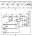
- the remote controller 10 includes a CPU (Central Processing Unit) 10a, a ROM (Read Only Memory) 10b, a RAM (Random Access Memory) 10c, a hard disk 10d, a communication circuit 10f, a 7 SEG (SEGment) display component 10i, as shown in FIG. It consists of operation buttons 10j.
- a CPU Central Processing Unit
- ROM Read Only Memory
- RAM Random Access Memory
- hard disk 10d a hard disk
- a communication circuit 10f a 7 SEG (SEGment) display component 10i, as shown in FIG. It consists of operation buttons 10j.
- the CPU 10a performs overall control of the remote controller 10 by executing software processing according to a program stored in the ROM 10b or the hard disk 10d.
- the RAM 10c temporarily stores information (that is, data) to be processed when the CPU 10a executes the program.
- the hard disk 10d stores a table (that is, a table) in which various information (that is, data) is stored.
- the remote controller 10 may include a flash memory instead of the hard disk 10d.
- the communication circuit 10f serially communicates data with the air conditioners 110 to 140 connected via a serial line.
- the 7SEG display component 10i displays various codes such as an error code, for example, in accordance with a signal output from the CPU 10a.
- the operation button 10j inputs a signal corresponding to a user operation.
- the air conditioner 110 includes, for example, an indoor unit (that is, an air conditioner) 110i installed on the ceiling of the room and an outdoor unit.
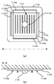
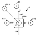
- An air inlet 111 and air outlets 112o to 115o as shown in FIG. 3A are formed on the lower surface of the indoor unit 110i, and a position detector 119 is installed at the center.
- the indoor unit 110i sucks indoor air from the air intake port 111, adjusts the intake air to the temperature and humidity specified by the remote controller 10, and then the air blowing port 112o in the specified direction by the specified amount.
- blades 112b to 115b for controlling the blowing direction as shown in FIGS. 3A and 3B are provided at the blowing ports 112o to 115o.
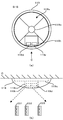
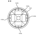
- the position detector 119 installed on the lower surface of the indoor unit 110i is covered with a semitransparent hemispherical cover as shown in FIG. 3B which is a side view of the indoor unit 110i. Inside the position detector 119, there is a rotating shaft 119x, a rotating stage 119s, and one transmitting / receiving unit 119t as shown in FIG. 4A, which is a cross-sectional view along the BB plane in FIG. 3B. Built in.
- the rotation axis 119x is a rotation axis of the rotation stage 119s and is an axis substantially perpendicular to the lower surface of the indoor unit 110i.
- the rotating shaft 119x is connected to a stepping motor (not shown) and rotated by 90 ° by the stepping motor according to the control of an infrared receiving IC (Integrated Circuit) constituting the receiving unit 119r. For this reason, the rotation stage 119s fixed to the rotation shaft 119x rotates by 90 ° with the rotation of the rotation shaft 119x.
- the transmission / reception unit 119t is fixed to the lower surface of the rotary stage 119s as shown in FIG. 4 (b) illustrating the position detector 119 from the C direction shown in FIG. 4 (a).
- the transmission / reception unit 119t is installed in one of the four areas obtained by dividing the lower surface of the rotary stage 119s as shown in FIG. 4A by a half line extending from the rotary shaft 119x to the cover of the position detector 119. Yes.
- the transmission / reception unit 119t transmits the infrared signal by transmitting the cover of the position detector 119 from the rotation shaft 119x, and the cover from the direction substantially matching the direction in which the transmission unit 119d transmits the infrared signal.
- a receiving unit 119r that receives the transmitted infrared signal. For this reason, when the rotary stage 119s rotates 90 ° around the rotation axis 119x, the transmission / reception direction of the infrared signal by the transmission / reception unit 119t rotates 90 ° around the rotation axis 119x.
- the transmission unit 119d is configured to include an infrared transmission LED (Light Emitting Diode), and emits infrared rays by being turned on according to the control of the infrared reception IC configuring the reception unit 119r.
- the receiving unit 119r configured to include the infrared receiving IC receives the infrared signal transmitted from the portable device 201 to 208.
- the receiving unit 119r configured by an infrared receiving IC includes a CPU 119a, a ROM 119b, a RAM 119c, a communication circuit 119f, an I / O port 119io, and a light receiving unit 119p as shown in FIG.
- the CPU 119a, ROM 119b, and RAM 119c are the same as the CPU 10a, ROM 10b, and RAM 10c of FIG.
- the communication circuit 119f performs serial communication with the remote controller 20.
- the I / O port 119io outputs a signal output from the CPU 119a to the transmission unit 119d and the stepping motor.
- the light receiving unit 119p inputs a signal transmitted from the portable devices 201 to 208 to the CPU 119a.
- the portable devices 201 to 208 have identification information (hereinafter referred to as device ID) for identifying each device.
- the device IDs of the portable devices 201 to 208 are different numbers “1” to “8”, respectively. Since the portable devices 201 to 208 have the same configuration, the portable device 201 will be mainly described below.
- the portable device 201 is a portable device, and includes a light detection unit 201r, an amplification unit 201p, an adjustment unit 201f, a transmission unit 201s, a measurement unit 201m, an input unit 201t, and an infrared reception IC 210 as illustrated in FIG. It is comprised including.
- the light detection unit 201r includes, for example, a photodiode. When detecting the infrared ray emitted from the transmission unit 119d of the position detector 119, the light detection unit 201r generates a voltage corresponding to the intensity of the detected infrared ray.
- the amplification unit 201p is configured to include, for example, an operational amplifier (hereinafter referred to as an operational amplifier), and amplifies the voltage generated in the light detection unit 201r.
- the adjustment unit 201f is controlled by the infrared receiving IC 210 to increase or decrease the degree to which the amplification unit 201p amplifies the voltage. For example, assuming that the ratio of the value after amplification to the voltage value before amplification is the amplification factor, the adjustment unit 201f adjusts the amplification factor of the amplification unit 201p to the rate specified by the infrared receiving IC 210.
- the transmission unit 201s includes an infrared transmission LED and is controlled by the infrared reception IC 210 to transmit various signals by infrared.
- the measurement unit 201m includes a temperature sensor, and inputs a signal representing the temperature measured by the temperature sensor to the infrared receiving IC 210.
- the input unit 201t is configured to include an operation button, and inputs set temperature information representing a set temperature to the infrared receiving IC 210 in accordance with a user operation.
- the infrared receiving IC 210 includes a CPU 210a, a ROM 210b, a RAM 210c, an ADC (Analog-to-Digital Converter) 210v, and an I / O (Input- / Output) port 210io.
- the CPU 210a, ROM 210b, and RAM 210c are the same as the CPU 10a, ROM 10b, and RAM 10c in FIG.
- the ADC 210v inputs digital data representing the value of the voltage amplified by the amplifier 201p to the CPU 210a.
- the I / O port 210io inputs a digital signal representing the room temperature measured by the measurement unit and set temperature information input by the input unit 201t to the CPU 210a.
- the I / O port 210io outputs a control signal output from the CPU 210a to the transmission unit 201s.
- the reception unit 119r that constitutes the position detection unit 119 illustrated in FIG. 5A detects the positions of the portable devices 201 to 208 using the hardware illustrated in FIG. Perform detection processing.
- the CPU 119a of the reception unit 119r functions as a reception unit 191, a detection unit 192, a correction unit 194, and a control unit 195 as illustrated in FIG.
- the CPU 119a functions as the storage unit 193 in cooperation with the ROM 119b and the RAM 119c.
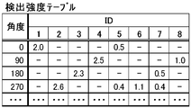
- the storage unit 193 stores a detection intensity table as shown in FIG. Each detection intensity table is detected by rotation angle information indicating the rotation angle of the rotation stage 119s, a device ID for identifying the portable device, and the infrared device transmitted when the rotation stage 119s is at the rotation angle. And a plurality of records stored in association with detected intensity information representing the detected intensity (hereinafter referred to as detected intensity).
- the rotation angle of the rotation stage 119s passes through the rotation axis 119x of the rotation stage 119s (that is, the approximate center of the indoor unit 110i), and is a predetermined coordinate axis substantially parallel to the rotation surface of the rotation stage 119s. Expressed as an angle with X. Similarly, a direction from the indoor unit 110i to a certain position (hereinafter referred to as a direction based on the indoor unit 110i) is also expressed by an angle with the coordinate axis X.
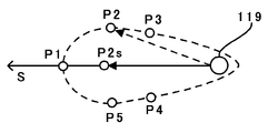
- the infrared rays transmitted from the position detector 119 of the indoor unit 110i shown in FIGS. 4A and 4B have directivity. For this reason, although the distances from the position detector 119 mounted on the indoor unit 111i are different at points P1 to P5 as shown in FIG. become. That is, when infrared rays are transmitted in the direction S as shown in FIG. 10, the point P1 in the direction S with respect to the indoor unit 110i is the farthest from the indoor unit 110i among the points P1 to P5. First, infrared rays having the same intensity as the other points P2 to P5 are detected.
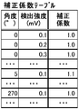
- the storage unit 193 stores a correction coefficient table as shown in FIG.
- This correction coefficient table is obtained when the direction information indicating the direction from the indoor unit 110i toward a certain point (for example, P2) and the infrared ray is transmitted from the indoor unit 110i in the direction S (for example, the point P2).
- the detected detection intensity is associated with correction coefficient information representing a correction coefficient for correcting the detected intensity to a detected intensity detected at a point in the direction S (for example, the point P2s) that is away from the indoor unit 110i by the same distance as the point. Saved.
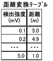
- the storage unit 193 stores a distance conversion table as shown in FIG.
- This distance conversion table shows distance information indicating a distance from the indoor unit 110i (hereinafter referred to as a distance with the indoor unit 110i as a reference) and the intensity of infrared rays detected at a point away from the position detector 119 by the distance. It has a plurality of records stored in association with the detected detection intensity information.
- the storage unit 193 stores a result table as shown in FIG.
- This result table includes the device ID of the portable device, information indicating the position of the portable device with respect to the indoor unit 110i (that is, the distance and direction with reference to the indoor unit), and the room temperature measured by the portable device. And a plurality of records stored in association with the set temperature information input to the portable device.
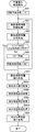
- the position detector 119 executes the position detection process of FIG. 6 at a predetermined cycle, for example, once a day.
- the control unit 195 in FIG. 7 performs a variable (hereinafter referred to as a rotation angle variable) that stores a value indicating the rotation angle of the rotation stage 119s in FIG. Then, the initial value “0 °” is substituted (step S01). Next, detection intensity information reception processing for receiving detection intensity information as shown in FIG. 14A is executed (step S02).
- a rotation angle variable a variable that stores a value indicating the rotation angle of the rotation stage 119s in FIG.
- the control unit 195 in FIG. 7 starts transmission of an infrared signal representing the value “1” (hereinafter referred to as infrared “1”).
- infrared “1” an infrared signal representing the value “1”
- the transmitter 119d in FIG. 4A is controlled (step S11).
- transmitting the infrared signal representing the value “1” means turning on the infrared transmission LED constituting the transmission unit 119d.
- the control unit 195 waits for a predetermined time F while the infrared transmission LED is lit (that is, the infrared output is continued) (step S12).
- Information representing the predetermined time F is stored in the storage unit 193 in advance.
- the predetermined time F when the portable device 201 is installed within a predetermined range, after the infrared transmission LED is turned on, the photodiode constituting the light detection unit 201r in FIG. 5B detects light. And a time sufficient for generating a predetermined voltage and a time longer than a time sufficient for the amplifier 201p to amplify the voltage by a predetermined ratio.
- the predetermined time F is set in advance to a time sufficient for the portable devices 201 to 208 to detect the lighting of the infrared transmission LED, based on the response speed of the photodiode and the response speed of the amplification unit 201p. ing.
- the control unit 195 controls the transmission unit 119d to end the transmission of the infrared signal representing the value “1” (that is, infrared “1”) (step S13).
- the control unit 195 causes the transmission unit 119d to transmit a signal indicating a request for transmitting the detection intensity information (hereinafter, referred to as a detection intensity information transmission request signal) (step S14).
- the position detector 119 does not transmit infrared rays while receiving detection intensity information from one portable device over a period of time T. This is to prevent the infrared rays transmitted by the position detector 119 from interfering with the infrared rays received by the position detector 119.
- the portable devices 201 to 208 that transmit the detected intensity information transmit the detected intensity information over the time T after waiting in the standby period calculated using the following equation (1).
- the device IDs of the portable devices 201 to 208 are different, two or more of the portable devices 201 to 208 do not transmit infrared rays at the same time. This is to prevent interference.
- the total reception time required for the position detector 119 to receive the detection intensity information from all of the portable devices 201 to 208 is calculated as a value “8T” using the following equation (2).
- Information representing the total number n of portable devices constituting the air conditioning system 1 and information representing the time length T for receiving detected intensity information from the portable devices are stored in the storage unit 193, respectively.
- Standby time (device ID-1) ⁇ time T (1)
- Total reception time total number of portable devices n ⁇ time T (2)
- step S15 the receiving unit 191 in FIG. 7 determines whether or not the total reception time (8T in this embodiment) has elapsed (step S15). At this time, if the receiving unit 191 determines that the total reception time has not elapsed (step S15; No), the device ID and the detected intensity information from any of the portable devices 201 to 208 are passed over the time T. Receive (step S16).
- the control unit 195 determines whether or not the detected intensity represented by the acquired detected intensity information exceeds a predetermined value V (step S17).
- Information representing the predetermined value V is stored in the storage unit 193.
- the predetermined value V is a threshold value used to determine whether or not the intensity of light detected by the light detection unit 201r of the portable device 201 illustrated in FIG. 5B is at a saturation level. That is, for example, when the intensity of light detected by the light detection unit 201r is greater than the predetermined value V because the distance from the indoor unit 110i is shorter than the predetermined distance L, the voltage generated by the light detection unit 201r is It does not become larger than the predetermined voltage v or becomes difficult to increase. For this reason, when the light intensity detected by the light detection unit 201r exceeds the predetermined value V (that is, step S17; Yes), the light intensity has reached the saturation level of the light detection unit 201r. Determined.
- step S17 When it is determined in step S17 that the detected intensity exceeds the predetermined value V (step S17; Yes), the control unit 195 decreases the amplification factor of the amplification unit 201p shown in FIG.
- the transmission unit 119d is controlled so as to transmit a signal representing an amplification factor adjustment request for performing adjustment to be performed (step S18).
- the control unit 195 associates the device ID acquired in step S16 with the adjusted information indicating that the amplification factor of the device identified by the device ID has already been adjusted, and saves it in the storage unit 193.
- the adjusted information storing process is executed (step S19). Thereafter, when the total reception time elapses after the acquired detection intensity information is discarded, the above processing is repeated from step S11. This is because it is sufficient to acquire information representing a more accurate detection intensity in the next execution.
- control unit 195 obtains an amplification factor to be adjusted to increase the amplification factor of the amplification unit 201p by a predetermined rate R in step S18. You may control to transmit the signal showing an adjustment request.
- step S17 If it is determined in step S17 that the detected intensity does not exceed the predetermined value V (that is, the detected intensity is equal to or lower than the predetermined value V) (step S17; No), the above process is repeated from step S15.
- step S15 when determining that the total reception time has elapsed (step S15; Yes), the reception unit 191 ends the detection intensity information reception process.
- step S21 When the portable device 201 detects infrared rays with the light detection unit 201r in FIG. 5, the portable device 201 starts detection intensity information transmission processing as shown in FIG. 14B, and detects the received infrared detection intensity (that is, in FIG. 5). The maximum value of the voltage amplified by the amplification unit 201p is held (step S21). The process of step S21 is repeated until the detected intensity information transmission request signal transmitted in step S14 of FIG. 14A is received from the indoor unit 110i (step S22; No).
- step S21 When the portable device 201 receives the detected intensity information transmission request signal (step S22; Yes), after waiting for a waiting period determined by the device ID of the portable device 201 (step S23), the portable device 201 and the device ID of the portable device 201, step S21 The detection intensity information representing the maximum value of the detection intensity held in (2) is transmitted by infrared from the transmission unit 201s in FIG. 5B (step S24). Thereafter, if the portable device 201 does not receive the signal indicating the amplification factor adjustment request within the predetermined time (step S25; No), the detection intensity information transmission process is terminated.
- step S25 when a signal representing an amplification factor adjustment request is received within a predetermined time (step S25; Yes), the amplification factor of the amplification unit 201p in FIG. 5 is decreased by a predetermined factor R in response to the request.
- step S26 After the adjustment by the adjustment unit 201f (step S26), the detection intensity information transmission process is terminated.
- the correction unit 194 of FIG. 7 After receiving the detected intensity information and the device ID in step S02 of FIG. 6, the correction unit 194 of FIG. 7 searches for the device ID stored in the storage unit 193 in association with the adjusted information. Thereafter, the correction unit 194 corrects the detection intensity information of the device identified by the searched device ID to information indicating the intensity increased by a predetermined rate R with respect to the detection intensity indicated by the detection intensity information. Information representing the rate R is stored in the storage unit 193.
- control unit 195 associates the information indicating the rotation angle stored in the rotation angle coefficient in step S01 or step S06 with the detected intensity information and the device ID and stores them in the detected intensity table of FIG. (Hereinafter, referred to as detection intensity information storage processing) is performed (step S03).
- the detection unit 192 performs the detection intensity information reception process of step S02 in all angles (that is, 0 °, 90 °, 180 °, and 270 °) that the rotation angle of the rotation stage 119s in FIG. It is discriminated whether or not it has been executed (step S04).
- the control unit 195 rotates the rotary stage 119s of FIG. 4 by 90 degrees (step S05).
- step S06 the control unit 195 repeats the above processing from step S02.
- step S04 when the detection unit 192 determines that the detection intensity information reception process has been performed for all angles (step S04; Yes), the detection intensity information and the rotation angle information stored in the detection intensity table illustrated in FIG. The detected intensity information reading process for reading out and the like is executed (step S07).
- the detecting unit 192 moves each direction from the indoor unit 110i to the portable device 201 to 208. That is, a relative direction detection process for detecting (relative directions of the portable devices 201 to 208 with respect to the indoor unit 110i) is executed (step S08a).
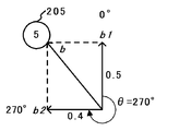
- the portable device 205 identified by the device ID “5” detects light with an intensity “0.5” when the rotation angle is “0 °”, and the rotation angle Information indicating that light having an intensity of “0.4” is detected at “270 °” is stored.
- the detection unit 192 has a vector b1 having a length of “0.5” toward the direction of the angle “0 °” as illustrated in FIG. 16 and “0.4 toward the direction of the angle“ 270 ° ”.
- the detection unit 192 detects the direction of the calculated vector b as the relative direction of the portable device 205 with respect to the indoor unit 110i.
- the correction unit 194 is represented by the direction information indicating the relative direction represented by the calculated direction of the vector b and the length of the vector b for each of the mobile devices 201 to 208.
- a correction coefficient reading process for reading the correction coefficient information associated with the detection intensity information indicating the detection intensity from the correction coefficient table of FIG. 11 is executed (step S08b).
- the correction unit 194 multiplies the detection intensity represented by the magnitude of the calculated vector b by the correction coefficient represented by the read correction coefficient information for each of the portable devices 201 to 208.
- a detection intensity correction process for correcting the detection intensity is executed (step S08c).
- the detection unit 192 performs a relative position detection process for detecting the relative position with respect to the indoor unit 110i based on the corrected detection intensity for each of the portable devices 201 to 208 (step S08d). Specifically, the detection unit 192 reads distance information associated with detection intensity information indicating the corrected detection intensity from the distance conversion table of FIG. Next, the detection unit 192 detects a position represented by the relative distance represented by the read distance information and the relative direction detected in step S08a as a relative position.
- control unit 195 associates the device ID with the position information indicating the relative position (that is, the relative direction and the relative distance) of the device identified by the device ID, and stores it in the result table shown in FIG. After executing the detected position information storing process (step S09), the position detecting process is terminated.
- the position detector 119 transmits, by infrared transmission, a signal indicating a request for shifting to the power saving mode for requesting the portable devices 201 to 208 to shift to the power saving mode when the position detection processing for the air conditioning apparatus 110 is completed.
- the mobile devices 201 to 208 mainly consume the power by stopping the operations of the light detection unit 201r and the infrared reception IC 210 including the photodiodes in FIG. Reduce. Thereafter, the portable devices 201 to 208 power on the light detection unit 201r and the infrared reception IC 210 intermittently at a predetermined interval such as an interval of 10 minutes.
- the position detector 119 receives the portable devices 201 to 208 at the timing when the portable devices 201 to 208 turn on the power (hereinafter referred to as the power-on timing).
- the measured temperature information receiving process as shown in FIG. 17A is executed to receive the measured temperature information indicating the temperature measured by.
- the position detector 119 substitutes a value representing “0 °” for the rotation angle variable, similarly to step S01 in FIG. 6 (step S31).
- the position detector 119 repeats the process of step S32 after sleeping for a predetermined time.
- a signal indicating a request for transmission of measured temperature information indicating the measured temperature (hereinafter referred to as a measured temperature information transmission request).
- a signal (step S33).
- the position detector 119 like steps S15 and S16 of FIG. 14A, measures the device ID of the portable devices 201 to 208 and the temperature measured by the portable devices 201 to 208 during the total reception period.
- the information and the set temperature information respectively input to the portable devices 201 to 208 are received in association with each other (steps S34 and S35).
- the position detector 119 executes a measured temperature information storage process for storing the received device ID, the measured temperature information, and the set temperature information in the result table of FIG. 13 (step S36). Thereafter, similarly to steps S05 and S06 in FIG. 6, the rotation stage 119s in FIG. 4 is rotated by 90 °, and the value of the rotation angle variable is incremented by “90 °” (steps S37 and S38). Repeat the process.
- the portable devices 201 to 208 each start the measured temperature information transmission process of FIG.
- the measured temperature information transmission process executed by the portable device 201 will be described, and the description of the measured temperature information transmission process executed by the portable devices 202 to 208 will be omitted.
- the portable device 201 When the portable device 201 receives the information indicating the measurement temperature information transmission request transmitted in step S33 in FIG. 17A after starting the measurement temperature information transmission process (step S41), the portable device 201 in FIG.
- the room temperature (that is, room temperature) is measured by the measuring unit 201m (step S42).
- the device ID, the measured temperature information, and the set temperature information are transmitted by infrared (step S44). Then, the execution of the measured temperature information transmission process is terminated.
- the position detector 119 refers to the measured temperature information and the set temperature information stored in association with the same device ID in the detection result table of FIG. 13 at the predetermined interval such as 10 minutes.
- the difference between the room temperature represented by the referenced measured temperature information and the set temperature represented by the referenced set temperature information is calculated.
- the position detector 119 may calculate the difference between the room temperature represented by the measured temperature information referred to and the set temperature set in the remote controller 20 by the user.
- the set temperature is stored in the RAM 10c or the hard disk 10d of the remote controller 20 in FIG. 2.
- the position detector 119 receives the set temperature from the remote controller 20, it stores it in the storage unit 193.
- the position detector 119 specifies a position where the calculated difference is larger than the predetermined temperature among the detected positions of the portable devices 201 to 208. Thereafter, the position detector 119 controls the air volume, direction, temperature, and humidity (that is, the blowing state) of the air blown from the air conditioner 110 based on the calculated difference and the specified position. Specifically, when the difference between the room temperature and the set temperature at a position farther than a predetermined distance from the indoor unit 110i of the air conditioner 110 exceeds the predetermined temperature, the position detector 119 winds in the direction of the position.
- 3 (a) and 3 (b) are controlled so as to be sent, or the amount of air blown from the blowing ports 112o to 115o in FIG. 3 (a) is increased.
- the position detector 119 controls the air temperature to be blown from the air blowing ports 112o to 115o and the air to be blown when the calculated difference exceeds the predetermined temperature and the room temperature is higher than the set temperature. Control is performed to lower the humidity. If the room temperature is lower than the set temperature, control is performed to increase the air temperature. This control process may be executed by the remote controller 20 using the hardware shown in FIG.
- the portable devices 201 to 208 measure the room temperature with the measuring unit 201m in FIG. 5B, and the position detector 119 blows air from the air conditioner 110 based on the measured room temperature.
- the portable devices 201 to 208 measure the humidity of the room in which the air conditioner 110 is installed by the measuring unit 201m in FIG. 5B, and the position detector 119 uses the air conditioner based on the measured humidity.
- or 140 is employable.
- the portable device 201 inputs set temperature information according to the user's operation at the input unit 201t in FIG. 5B, and the position detector 119 is the setting input by the portable device 201. It demonstrated as controlling the ventilation state of the air conditioning apparatus 110 based on the difference of the preset temperature represented by temperature information, and the room temperature measured with the portable apparatus 201.
- FIG. the present invention is not limited to this, and the portable device 201 inputs the set humidity information according to the user's operation at the input unit 201t, and the position detector 119 receives the set humidity information input by the portable device 201.
- the structure which controls the ventilation state of the air conditioning apparatus 110 based on the difference between the set humidity represented by the humidity measured by the portable device 201 can be employed. Moreover, you may combine the said structure and the structure of this embodiment.
- the position detector 119 transmits infrared rays, and the portable devices 201 to 209 detect the intensity of infrared rays transmitted from the position detector 119.
- the present invention is not limited to this. is not.
- the position detector 119 may transmit visible light, ultraviolet light, or electromagnetic waves, and the portable devices 201 to 209 may detect the intensity of visible light, ultraviolet light, or electromagnetic waves transmitted from the position detector 119.
- the air blowing state of the indoor unit 110i and the like is controlled based on the distance detected based on the detected intensity of light or electromagnetic waves by the portable devices 201 to 208 and the measured room temperature or humidity, For example, even when the installation positions of the portable devices 201 to 208 change, the room temperature or humidity at the installation positions of the portable devices 201 to 208 can be adjusted more accurately than before.
- the direction from the indoor unit 110i or the like to the portable devices 201 to 208 is determined based on the direction in which the light or electromagnetic wave is transmitted and the intensity at which the light or electromagnetic wave is detected in the direction. For detection, for example, even when the installation position of the portable devices 201 to 208 changes, the installation positions of the portable devices 201 to 208 can be detected more accurately than before.
- the transmission / reception unit 119t of the position detector 119 that transmits light or electromagnetic waves is rotated, it is possible to detect the installation positions of the portable devices 201 to 209 in a wider range than when the position detector 119 is not rotated.
- the detected intensities detected by the portable devices 201 to 208 are After correcting to the detection intensity detected by the portable device located in the predetermined direction S, the distance from the indoor unit 110i or the like to the portable devices 201 to 208 is detected based on the corrected detection intensity. For this reason, the distance from the indoor unit 110i or the like can be detected more accurately with respect to a plurality of portable devices with fewer light or electromagnetic wave transmission directions.
- the difference between the set temperature represented by the information input from each of the portable devices 201 to 208 carried by the user and the room temperature observed from each of the portable devices 201 to 208, or the input Since the humidity of the indoor unit is controlled based on the difference between the set humidity represented by the information and the humidity observed by each of the portable devices 201 to 208 and the distance from the indoor unit to the portable devices 201 to 208 Even if the user moves, the room temperature or humidity set by the user can be realized more reliably than before.
- the light intensity detected by the light detection unit 201r is higher than the predetermined intensity.
- the position detector 119 mounted on the indoor unit 110i transmits a signal representing an amplification factor adjustment request for reducing the degree to which the amplification unit 201p amplifies the voltage. For this reason, if the degree to which the portable device 201 amplifies the voltage according to the signal is lowered, the distance from the indoor unit 110i to the portable device 201 can be detected more accurately than before. The same applies to the portable devices 202 to 208.
- the light intensity detected by the light detection unit 201r that is the light detection unit is higher than the predetermined intensity. If it becomes smaller, the position detector 119 mounted on the indoor unit 110i transmits a signal representing an amplification factor adjustment request for increasing the degree of amplification of the voltage by the amplifying unit 201p. For this reason, if the level which the portable apparatus 201 amplifies a voltage according to the said signal is raised, the distance from the indoor unit 110i to the portable apparatus 201 can be detected more correctly than before.
- the module used for infrared communication and the module for measuring the intensity of infrared rays often have a slower response speed than the module for measuring the intensity of infrared rays.
- the module that measures the intensity of infrared rays tends to increase the manufacturing cost of the module due to the characteristic that the voltage generated by the light detection needs to be further amplified, so the increase in manufacturing cost is suppressed by reducing the response speed It is because there are many things to do. For this reason, in order to measure the infrared intensity more accurately than before, the LED is transmitted over a longer time than the continuous lighting time during infrared communication by transmitting a signal representing a continuous value “1” by infrared transmission. It needs to be lit.
- the transmission unit 119d of the position detector 119 shown in FIG. 4 is lit for a longer time than when transmitting signals when the portable devices 201 to 208 detect infrared intensity. Moreover, the figure transmission part 119d light-emits over the predetermined time F longer than the response time of the optical detection part 201r shown in 5 (b), and the response time of the amplification part 201p. Furthermore, the portable device 201 does not measure the reception intensity during communication with the position detector 119 mounted on the indoor unit 110i.
- the light receiving intensity of the light emitted from the position detector 119 is more accurately determined than before, regardless of the response speeds of the light detection unit 201r and the amplification unit 201p (that is, the light detection speed and the voltage amplification speed). It can be measured.
- the position detector 119 receives the device ID and the detected intensity information after transmitting the detected intensity information transmission request signal in steps S14 to S16 in FIG. Further, in steps S22 to S24 in FIG. 14B, the portable device 201 has been described as transmitting the device ID and the detected strength information after receiving the detected strength information transmission request signal.
- the present invention is not limited to this, and the position detector 119 transmits the detected intensity information after transmitting the infrared signal representing the value “1” (steps S51 to S53), as shown in FIG.
- a configuration can be adopted in which the device IDs and the detected intensity information of the portable devices 201 to 208 are acquired over the total reception time without transmitting the request signal (steps S54 and S55).
- the portable device 201 holds the maximum value of the received infrared detection intensity (step S61), and the held value (hereinafter referred to as the detection level) is not yet determined.
- the process of step S61 is repeated until the detection level changes by a predetermined value or more.
- the portable device 201 waits for a standby period determined by the device ID of the portable device 201 and then transmits the device ID and the detected intensity information (step S63).
- S64 configuration can be adopted.
- the undetected level refers to a value held by the portable device 201 when infrared rays are not detected, and is a value measured in advance to confirm the background noise level in advance. This undetected level is stored in the RAM 201c of the portable device 201.
- the portable device 201 since the portable device 201 transmits detection intensity information when the detection level changes from the undetected level by a predetermined value or more, the portable device 201 performs a simple operation compared to the detection intensity information transmission process of FIG. As a result, it is possible to transmit the detected intensity information to the position detector 119 of the indoor unit 110i by infrared transmission while preventing interference caused by infrared transmission from the other portable devices 202 to 208. For this reason, since the operation can be realized using hardware such as an electronic circuit without the infrared receiving IC 210 of FIG. 5B, the manufacturing cost of the portable device 201 can be reduced.
- the position detector 119 has one transmission / reception unit 119t that transmits and receives infrared rays.
- the rotation stage 119s to which the transmission / reception unit 119t is fixed is connected to the rotation shaft 119x.
- the direction in which the position detector 119 transmits and receives infrared rays is changed to four directions of 0 °, 90 °, 180 °, and 270 ° with reference to the X axis in FIG.
- the position detector 119 can employ a configuration having four transmission / reception units 119t that transmit and receive infrared rays in four directions of 0 °, 90 °, 180 °, and 270 °, respectively.
- the position detection device 119 can employ a configuration in which infrared communication is performed using all of the four transmission / reception units 119t.
- the directivity of the infrared rays transmitted from the position detector 119 is substantially the same even in almost all angles from 0 ° to 360 ° (that is, the directivity is hemispherical).
- the intensity of the detected infrared rays changes substantially in accordance with the distance from the position detector 119.
- the position detection unit 119 selects one of the four transmission / reception units 119t as necessary, and uses the selected transmission / reception unit 119t to perform infrared rays.
- a communication configuration can be employed. According to this configuration, since the position detector 119 can change the infrared transmission / reception direction without rotating the rotary stage 119s, the communication direction can be changed in a short time.
- the portable device 201 has been described as transmitting detection intensity information representing the maximum value of the detection intensity held in step S21 in step S24 of FIG. 14B, but the present invention is not limited to this. Absent.
- the maximum value of the detected intensity that is, before receiving the infrared signal having the value “1” that is a predetermined time L or more before the time when the detected intensity information transmission request signal is received (that is, A configuration for transmitting detection intensity information representing the level of background noise) and detection intensity information representing the maximum value of the detection intensity held in step S21, or the difference between the maximum values of these two detection intensities is used as the position detector 119. It is possible to adopt a configuration for detecting the received intensity of the infrared rays transmitted from. According to this configuration, it is possible to reduce the influence of background noise and accurately detect the received intensity of infrared rays transmitted from the position detector 119.
- the detection unit 192 is represented by the angle represented by the plurality of rotation angle information read from the detection intensity table of FIG. 8 and the detection intensity information.
- the relative direction of each of the portable devices 201 to 208 based on the indoor unit 110i is detected based on the detected intensity.
- the detection unit 192 detects the relative distance (that is, the angle represented by the plurality of rotation angle information read from the detection intensity table of FIG. 8 and the detection intensity represented by the detection intensity information (that is, It is possible to adopt a configuration in which the relative directions of the portable devices 201 to 208 are detected based on the distance based on the indoor unit 110i.
- the portable device 205 identified by the device ID “5” detects light of intensity “0.5” when the rotation angle is “0 °”, and rotates. Information indicating that light having an intensity of “0.4” is detected at an angle of “270 °” is stored. For this reason, in this configuration, the detection unit 192 uses the distance conversion table of FIG. 12 to calculate the distances L1 and L2 represented by information associated with the information representing the strengths “0.5” and “0.4”, respectively. To detect. Thereafter, the detection unit 192 calculates a combined vector obtained by combining the vector having the length L1 toward the direction of the angle “0 °” and the vector having the length L2 toward the direction of the angle “270 °”. The direction of the calculated combined vector is detected as the relative direction of the portable device 205 with respect to the indoor unit 110i.
- the air conditioner system 1 can be configured from an existing position detector by applying a program as well as being able to provide the position detector 119 having a configuration for realizing the functions according to the present embodiment in advance. It is also possible to function as a position detector 119. That is, by applying a control program for realizing each functional configuration by the position detector 119 exemplified in the above embodiment so that a computer (such as a CPU) that controls an existing terminal device can be executed, this embodiment It can be made to function as position detector 119 which constitutes air harmony system 1 concerning.
- Such a program distribution method is arbitrary.
- the program can be distributed by being stored in a recording medium such as a memory card, a CD-ROM, or a DVD-ROM, or can be distributed via a communication medium such as the Internet.
- the air conditioning method of the present invention can be implemented using the air conditioning system 1.
- the present invention is suitable for an air conditioning system that harmonizes indoor air.
- Air Conditioning System 10 Remote Controller 10a CPU 10b ROM 10c RAM 10d hard disk 10f communication circuit 10i 7SEG display component 10j operation button 20 remote control 110-140 air conditioner 110i indoor unit 111 air inlet 112o-115o air outlet 112b-115b blade 119 position detector 119a CPU 119b ROM 119c RAM 119d Transmitter 119f Communication circuit 119g Infrared receiver IC 119io I / O port 119p light receiving unit 119s rotation stage 119t transmission / reception unit 119r reception unit 119x rotation axis 191 reception unit 192 detection unit 193 storage unit 194 correction unit 195 control unit 201 to 208 portable device 201f adjustment unit 201m measurement unit 201p amplification unit 201r Photodetector 201s Transmitter 201t Input unit 210 Infrared receiver IC 210a CPU 210b ROM 210c RAM 210io I / O port 210v ADC
Abstract
Description
温度又は湿度を計測する計測部を有する装置と、
前記装置に対して光又は電磁波を送信する室内機に搭載された送信部と、
前記送信された光又は電磁波の前記装置による検出強度を表す検出強度情報を受信する前記室内機に搭載された受信部と、
前記受信された検出強度情報で表される検出強度に基づいて前記室内機から前記装置までの距離を検出する検出部と、
前記検出された距離と、前記計測された温度又は湿度とに基づいて前記室内機の送風状態を制御する制御部と、を備える。
空気調和装置110は、例えば、部屋の天井に設置された室内機(つまり、エア・コンディショナー)110iと室外機とを含んで構成される。室内機110iの下面には、図3(a)に示すような吸気口111及び送風口112oから115oが形成され、中央部に位置検出機119が設置されている。室内機110iは、吸気口111から室内の空気を吸気し、吸気された空気をリモコン10により指定された温度及び湿度に調節してから、指定された量だけ、指定された方向へ送風口112oから115oから送風する。なお、送風口112oから115oには、図3(a)及び(b)に示すような送風方向を制御するブレード112bから115bが設けられている。
記憶部193は、図8に示すような検出強度テーブルを記憶する。それぞれの検出強度テーブルは、回転ステージ119sの回転角度を表す回転角度情報と、携帯装置を識別する装置IDと、回転ステージ119sが当該回転角度にあるときに送信された赤外線の当該携帯装置によって検出された強度(以下、検出強度という)を表す検出強度情報とを対応付けて保存された複数のレコードを有する。
総受信時間 = 携帯装置の総数n×時間T・・・(2)
10 リモートコントローラ
10a CPU
10b ROM
10c RAM
10d ハードディスク
10f 通信回路
10i 7SEG表示部品
10j 操作ボタン
20 リモコン
110~140 空気調和装置
110i 室内機
111 吸気口
112o~115o 送風口
112b~115b ブレード
119 位置検出機
119a CPU
119b ROM
119c RAM
119d 送信部
119f 通信回路
119g 赤外線受信IC
119io I/Oポート
119p 受光部
119s 回転ステージ
119t 送受信部
119r 受信部
119x 回転軸
191 受信部
192 検出部
193 記憶部
194 補正部
195 制御部
201~208 携帯装置
201f 調整部
201m 計測部
201p 増幅部
201r 光検出部
201s 送信部
201t 入力部
210 赤外線受信IC
210a CPU
210b ROM
210c RAM
210io I/Oポート
210v ADC
Claims (9)
- 温度又は湿度を計測する計測部を有する装置と、
前記装置に対して光又は電磁波を送信する室内機に搭載された送信部と、
前記送信された光又は電磁波の前記装置による検出強度を表す検出強度情報を受信する前記室内機に搭載された受信部と、
前記受信された検出強度情報で表される検出強度に基づいて前記室内機から前記装置までの距離を検出する検出部と、
前記検出された距離と、前記計測された温度又は湿度とに基づいて前記室内機の送風状態を制御する制御部と、を備える、
空気調和システム。 - 前記室内機に搭載された送信部は、複数の方向へ光又は電磁波を送信し、
前記検出部は、前記光又は電磁波が送信された複数の方向と、前記複数の方向にそれぞれ送信された光又は電磁波の前記装置における検出強度とに基づいて、前記室内機から前記装置へ向かう方向と、前記室内機から前記装置までの距離とを検出し、
前記制御部は、前記検出された方向及び距離と、前記計測された温度又は湿度とに基づいて前記室内機の送風状態を制御する、
請求項1に記載の空気調和システム。 - 前記室内機に搭載された送信部による光又は電磁波の送信方向を変更する変更部を、さらに備え、
前記検出部は、前記変更された送信方向と、前記送信方向へ送信された光又は電磁波の検出強度とに基づいて、前記室内機から前記装置までの距離と、前記室内機から前記装置へ向かう方向とを検出する、
請求項2に記載の空気調和システム。 - 前記室内機に搭載された送信部が送信する光又は電磁波は指向性を有し、
前記室内機を基準とした方向を表す方向情報と、前記室内機に搭載された送信部から光又は電磁波が所定の方向へ送信された場合に、前記方向情報で表される方向に位置する装置で検出された検出強度を、当該装置と同じ距離だけ前記室内機から離れた前記所定の方向の位置で検出される検出強度に補正する補正係数を表す情報とを対応付けて記憶する記憶部と、
前記検出された方向を表す情報と対応付けられた情報で表される補正係数を用いて、前記受信された検出強度情報で表される検出強度を補正する補正部と、をさらに備え、
前記検出部は、前記補正された検出強度に基づいて前記室内機から前記装置までの距離を検出する、
請求項2に記載の空気調和システム。 - 前記装置は、
設定温度を表す設定温度情報又は設定湿度を表す設定湿度情報を入力する入力部と、
前記入力された設定温度情報又は設定湿度情報を送信する送信部と、をさらに有する携帯型の装置であり、
前記室内機に搭載された受信部は、前記送信された設定温度情報又は設定湿度情報を受信し、
前記制御部は、前記計測された温度と、前記受信された設定温度情報で表される設定温度との差異、又は前記計測された湿度と、前記受信された設定湿度情報で表される設定湿度との差異と、前記検出された距離とに基づいて前記室内機の送風状態を制御する、
請求項1に記載の空気調和システム。 - 前記装置は、
前記室内機に搭載された送信部から発せられた光を検出して電圧を生じさせる光検出部と、
前記光検出部で生じた電圧を増幅する増幅部と、
前記増幅部が電圧を増幅する程度を調整する調整部と、を備え、
前記送信部は、前記増幅部で増幅された電圧を表す情報を、前記光検出部で検出された光の強度を表す検出強度情報として送信し、
前記室内機に搭載された送信部は、前記受信した検出強度情報で表される検出強度が所定の強度よりも大きい場合に、前記増幅部が電圧を増幅する程度をより低く調節するように求める信号を送信する、
請求項1に記載の空気調和システム。 - 前記装置は、
前記室内機に搭載された送信部から発せられた光を検出して電圧を生じさせる光検出部と、
前記光検出部で生じた電圧を増幅する増幅部と、
前記増幅部が電圧を増幅する程度を調整する調整部と、を備え、
前記送信部は、前記増幅部で増幅された電圧を表す情報を、前記光検出部で検出された光の強度を表す検出強度情報として送信し、
前記室内機に搭載された送信部は、前記受信した検出強度情報で表される検出強度が所定の強度よりも小さい場合に、前記増幅部が電圧を増幅する程度をより高く調節するように求める信号を送信する、
請求項1に記載の空気調和システム。 - 前記室内機に搭載された送信部は、点滅により前記信号を送信し、前記装置が前記光の強度を検出する場合には、前記信号を送信する場合よりも長い時間に亘って点灯する、
請求項6又は7に記載の空気調和システム。 - 装置が温度又は湿度を計測する計測ステップと、
室内機から前記装置に対して光又は電磁波を送信する送信ステップと、
前記送信された光又は電磁波の前記装置による検出強度を表す検出強度情報を受信する受信ステップと、
前記受信された検出強度情報で表される検出強度に基づいて前記室内機から前記装置までの距離を検出する検出ステップと、
前記検出された距離と、前記計測された温度又は湿度とに基づいて前記室内機の送風状態を制御する制御ステップと、を有する、
空気調和方法。
Priority Applications (5)
| Application Number | Priority Date | Filing Date | Title |
|---|---|---|---|
| US13/978,929 US9535431B2 (en) | 2011-01-28 | 2011-01-28 | Air-conditioning system and air-conditioning method |
| CN201180066072.0A CN103328903B (zh) | 2011-01-28 | 2011-01-28 | 空气调节系统以及空气调节方法 |
| EP11856760.1A EP2669591B1 (en) | 2011-01-28 | 2011-01-28 | Air-conditioning system and air-conditioning method |
| PCT/JP2011/051828 WO2012101831A1 (ja) | 2011-01-28 | 2011-01-28 | 空気調和システム及び空気調和方法 |
| JP2012554603A JP5485417B2 (ja) | 2011-01-28 | 2011-01-28 | 空気調和システム及び空気調和方法 |
Applications Claiming Priority (1)
| Application Number | Priority Date | Filing Date | Title |
|---|---|---|---|
| PCT/JP2011/051828 WO2012101831A1 (ja) | 2011-01-28 | 2011-01-28 | 空気調和システム及び空気調和方法 |
Publications (1)
| Publication Number | Publication Date |
|---|---|
| WO2012101831A1 true WO2012101831A1 (ja) | 2012-08-02 |
Family
ID=46580427
Family Applications (1)
| Application Number | Title | Priority Date | Filing Date |
|---|---|---|---|
| PCT/JP2011/051828 WO2012101831A1 (ja) | 2011-01-28 | 2011-01-28 | 空気調和システム及び空気調和方法 |
Country Status (5)
| Country | Link |
|---|---|
| US (1) | US9535431B2 (ja) |
| EP (1) | EP2669591B1 (ja) |
| JP (1) | JP5485417B2 (ja) |
| CN (1) | CN103328903B (ja) |
| WO (1) | WO2012101831A1 (ja) |
Cited By (5)
| Publication number | Priority date | Publication date | Assignee | Title |
|---|---|---|---|---|
| JP2014075784A (ja) * | 2012-09-12 | 2014-04-24 | Ricoh Co Ltd | 情報管理システム、無線端末及び周囲環境管理方法 |
| JP2014077598A (ja) * | 2012-10-11 | 2014-05-01 | Mitsubishi Electric Corp | 温度調節器、空気調和機、給湯器及び床暖房 |
| CN105988101A (zh) * | 2015-03-02 | 2016-10-05 | 广州松下空调器有限公司 | 两设备之间的定位装置及定位方法 |
| WO2019186703A1 (ja) * | 2018-03-27 | 2019-10-03 | 三菱電機株式会社 | 空気調和機システム、空気調和機およびリモートコントローラ |
| WO2019244219A1 (ja) * | 2018-06-18 | 2019-12-26 | 三菱電機株式会社 | 空気調和システム、空気調和方法、制御装置、及び、プログラム |
Families Citing this family (8)
| Publication number | Priority date | Publication date | Assignee | Title |
|---|---|---|---|---|
| CN104714508B (zh) * | 2013-12-13 | 2018-04-27 | 国民技术股份有限公司 | 家用电器、控制装置和基于电磁测距的控制系统 |
| US11105885B2 (en) * | 2014-08-06 | 2021-08-31 | Yogendra C Shah | System and methods for identifying the location of a device based on calibration information |
| WO2016058795A1 (de) | 2014-10-13 | 2016-04-21 | Güntner Gmbh & Co. Kg | Verfahren zum betreiben eines wärmeaustauschsystems und wärmeaustauschsystem |
| TWI573968B (zh) * | 2014-10-24 | 2017-03-11 | Chunghwa Telecom Co Ltd | 空調控制系統及其方法 |
| CN109564022B (zh) * | 2016-08-10 | 2021-11-09 | 三菱电机株式会社 | 空调机 |
| CN107830611A (zh) * | 2017-10-26 | 2018-03-23 | 山西彩云归科技有限公司 | 空气质量监控装置、空气过滤装置及空气质量监控方法 |
| CN110160129A (zh) * | 2019-07-05 | 2019-08-23 | 北海和思科技有限公司 | 一种基于用户位置温度和湿度值控加湿型电暖器的控制方法 |
| CN110671778A (zh) * | 2019-10-21 | 2020-01-10 | 宁波奥克斯电气股份有限公司 | 一种空调器的运行控制方法、装置空调器及存储介质 |
Citations (9)
| Publication number | Priority date | Publication date | Assignee | Title |
|---|---|---|---|---|
| JPH0658597A (ja) * | 1992-08-12 | 1994-03-01 | Toshiba Corp | 空気調和装置 |
| JPH06337154A (ja) * | 1993-05-27 | 1994-12-06 | Hitachi Ltd | 赤外線源検知器及び該検知器を用いた居住環境制御装置 |
| JP2921256B2 (ja) * | 1991-11-14 | 1999-07-19 | 三菱電機株式会社 | 空気調和機の制御装置及び人体検知センサー及び空気調和機 |
| JP2001025064A (ja) * | 1999-07-06 | 2001-01-26 | Sony Corp | 通信装置および方法、通信システム、並びに媒体 |
| JP2001349742A (ja) * | 2000-06-07 | 2001-12-21 | Sharp Corp | 歩行者誘導システム及び方法並びにこれに利用される記憶媒体 |
| JP2007127348A (ja) * | 2005-11-04 | 2007-05-24 | Yamatake Corp | 環境調整システム |
| JP4042480B2 (ja) | 2002-06-26 | 2008-02-06 | 三菱電機株式会社 | 空気調和装置 |
| JP2008241185A (ja) * | 2007-03-28 | 2008-10-09 | Fujitsu General Ltd | 無線リモコンを備えた機器 |
| JP2008309379A (ja) * | 2007-06-13 | 2008-12-25 | Mitsubishi Electric Corp | 空調用リモートコントローラおよび空気調和機並びに空気調和システム |
Family Cites Families (23)
| Publication number | Priority date | Publication date | Assignee | Title |
|---|---|---|---|---|
| JP3102906B2 (ja) * | 1991-01-30 | 2000-10-23 | 東芝キヤリア株式会社 | 空気調和装置 |
| US5180333A (en) * | 1991-10-28 | 1993-01-19 | Norm Pacific Automation Corp. | Ventilation device adjusted and controlled automatically with movement of human body |
| JP3262288B2 (ja) * | 1992-08-26 | 2002-03-04 | 東芝キヤリア株式会社 | 空気調和機の湿度制御装置 |
| CN1156232A (zh) * | 1995-09-15 | 1997-08-06 | 三星电子株式会社 | 空调器的操作控制系统 |
| US6002987A (en) * | 1996-03-26 | 1999-12-14 | Nikon Corporation | Methods to control the environment and exposure apparatus |
| KR0175625B1 (ko) * | 1996-08-02 | 1999-03-20 | 김광호 | 공기조화기의 루버구동제어장치 및 방법 |
| JPH10289006A (ja) * | 1997-04-11 | 1998-10-27 | Yamaha Motor Co Ltd | 疑似感情を用いた制御対象の制御方法 |
| KR100225637B1 (ko) * | 1997-05-23 | 1999-10-15 | 윤종용 | 공기조화기의 온도제어장치 |
| TW402676B (en) * | 1998-12-08 | 2000-08-21 | Sharp Kk | Air conditioner |
| JP4320889B2 (ja) | 2000-01-07 | 2009-08-26 | ソニー株式会社 | 赤外線リモコンの送信機と受信機間の相対的な位置関係を検出するための位置検出システム及び位置検出方法、並びに、赤外線リモコン受信機 |
| JP3374175B2 (ja) | 2000-01-27 | 2003-02-04 | 名古屋大学長 | 位置表示用データ送信機能付きデータ送信装置、(以下[発明の名称の続き]欄に記載) |
| US6978627B2 (en) * | 2002-01-31 | 2005-12-27 | Mitsubishi Denki Kabushiki Kaisha | Air conditioner control system, central remote controller, and facility controller |
| WO2008087959A1 (ja) * | 2007-01-17 | 2008-07-24 | Daikin Industries, Ltd. | 空調制御システム |
| KR100855000B1 (ko) * | 2007-04-27 | 2008-08-28 | 삼성전자주식회사 | 공기조화기 및 그 제어방법 |
| WO2009034720A1 (ja) * | 2007-09-14 | 2009-03-19 | Mitsubishi Electric Corporation | 測位システム、空調システム、照明システム |
| CN201141675Y (zh) * | 2007-11-02 | 2008-10-29 | 宁波奥克斯空调有限公司 | 一种利用遥控器检测环境温度的空调器 |
| JP5175562B2 (ja) * | 2008-01-28 | 2013-04-03 | シャープ株式会社 | 人物位置検出装置および空気調和機 |
| KR101253239B1 (ko) * | 2008-03-11 | 2013-04-23 | 삼성전자주식회사 | 공기조화기 |
| JP5111445B2 (ja) * | 2008-09-10 | 2013-01-09 | 三菱電機株式会社 | 空気調和機 |
| KR20100082888A (ko) * | 2009-01-12 | 2010-07-21 | 엘지전자 주식회사 | 공기조화기 및 그 제어방법 |
| JP5507231B2 (ja) * | 2009-12-16 | 2014-05-28 | 三洋電機株式会社 | 空気調和機 |
| JP5289392B2 (ja) * | 2010-07-16 | 2013-09-11 | 三菱電機株式会社 | 空気調和機 |
| JP5404548B2 (ja) * | 2010-07-26 | 2014-02-05 | 三菱電機株式会社 | 空気調和機 |
-
2011
- 2011-01-28 US US13/978,929 patent/US9535431B2/en not_active Expired - Fee Related
- 2011-01-28 EP EP11856760.1A patent/EP2669591B1/en active Active
- 2011-01-28 WO PCT/JP2011/051828 patent/WO2012101831A1/ja active Application Filing
- 2011-01-28 CN CN201180066072.0A patent/CN103328903B/zh not_active Expired - Fee Related
- 2011-01-28 JP JP2012554603A patent/JP5485417B2/ja active Active
Patent Citations (9)
| Publication number | Priority date | Publication date | Assignee | Title |
|---|---|---|---|---|
| JP2921256B2 (ja) * | 1991-11-14 | 1999-07-19 | 三菱電機株式会社 | 空気調和機の制御装置及び人体検知センサー及び空気調和機 |
| JPH0658597A (ja) * | 1992-08-12 | 1994-03-01 | Toshiba Corp | 空気調和装置 |
| JPH06337154A (ja) * | 1993-05-27 | 1994-12-06 | Hitachi Ltd | 赤外線源検知器及び該検知器を用いた居住環境制御装置 |
| JP2001025064A (ja) * | 1999-07-06 | 2001-01-26 | Sony Corp | 通信装置および方法、通信システム、並びに媒体 |
| JP2001349742A (ja) * | 2000-06-07 | 2001-12-21 | Sharp Corp | 歩行者誘導システム及び方法並びにこれに利用される記憶媒体 |
| JP4042480B2 (ja) | 2002-06-26 | 2008-02-06 | 三菱電機株式会社 | 空気調和装置 |
| JP2007127348A (ja) * | 2005-11-04 | 2007-05-24 | Yamatake Corp | 環境調整システム |
| JP2008241185A (ja) * | 2007-03-28 | 2008-10-09 | Fujitsu General Ltd | 無線リモコンを備えた機器 |
| JP2008309379A (ja) * | 2007-06-13 | 2008-12-25 | Mitsubishi Electric Corp | 空調用リモートコントローラおよび空気調和機並びに空気調和システム |
Non-Patent Citations (1)
| Title |
|---|
| See also references of EP2669591A4 |
Cited By (7)
| Publication number | Priority date | Publication date | Assignee | Title |
|---|---|---|---|---|
| JP2014075784A (ja) * | 2012-09-12 | 2014-04-24 | Ricoh Co Ltd | 情報管理システム、無線端末及び周囲環境管理方法 |
| JP2014077598A (ja) * | 2012-10-11 | 2014-05-01 | Mitsubishi Electric Corp | 温度調節器、空気調和機、給湯器及び床暖房 |
| CN105988101A (zh) * | 2015-03-02 | 2016-10-05 | 广州松下空调器有限公司 | 两设备之间的定位装置及定位方法 |
| CN105988101B (zh) * | 2015-03-02 | 2019-09-17 | 广州松下空调器有限公司 | 两设备之间的定位装置及定位方法 |
| WO2019186703A1 (ja) * | 2018-03-27 | 2019-10-03 | 三菱電機株式会社 | 空気調和機システム、空気調和機およびリモートコントローラ |
| WO2019244219A1 (ja) * | 2018-06-18 | 2019-12-26 | 三菱電機株式会社 | 空気調和システム、空気調和方法、制御装置、及び、プログラム |
| JPWO2019244219A1 (ja) * | 2018-06-18 | 2020-12-17 | 三菱電機株式会社 | 空気調和システム、空気調和方法、制御装置、及び、プログラム |
Also Published As
| Publication number | Publication date |
|---|---|
| JPWO2012101831A1 (ja) | 2014-06-30 |
| EP2669591A4 (en) | 2018-04-25 |
| EP2669591A1 (en) | 2013-12-04 |
| US9535431B2 (en) | 2017-01-03 |
| CN103328903A (zh) | 2013-09-25 |
| EP2669591B1 (en) | 2021-10-13 |
| US20130289777A1 (en) | 2013-10-31 |
| JP5485417B2 (ja) | 2014-05-07 |
| CN103328903B (zh) | 2016-01-20 |
Similar Documents
| Publication | Publication Date | Title |
|---|---|---|
| JP5485417B2 (ja) | 空気調和システム及び空気調和方法 | |
| US10922956B2 (en) | Device and method for controlling a plurality of targeted devices | |
| US20170013112A1 (en) | Intuitive way to point, access, and control appliances and other objects in building interiors | |
| WO2022156301A1 (zh) | 空调器的控制方法、终端设备、服务器、空调器控制系统 | |
| JPWO2018216088A1 (ja) | 人位置検知装置、人位置検知システム、人位置検知方法及びプログラム | |
| JP6972371B2 (ja) | 空気調和システム | |
| KR102075464B1 (ko) | 기기 식별 장치 및 그 기기의 제어 방법 | |
| CN111051784A (zh) | 空调控制装置、环境设定终端、空调控制方法以及程序 | |
| WO2017081721A1 (ja) | 空調制御システム | |
| CN108302698A (zh) | 空调器控制方法、系统和空调器 | |
| JP7004837B2 (ja) | 空気調和システム | |
| JP7136575B2 (ja) | 空調システム及び制御方法 | |
| JP5535125B2 (ja) | リモートコントローラ | |
| US20230189419A1 (en) | Selecting a sensor data processing method in accordance with a type of a lighting device | |
| JP2021085636A (ja) | 制御方法、プログラム、制御装置、及び制御システム | |
| KR101540262B1 (ko) | 원격제어장치 및 그 장치의 구동방법 | |
| US11463848B2 (en) | Electronic device for determining external electronic device having generated EM signal | |
| US20220166491A1 (en) | In-house relay device and support equipment for supporting same | |
| US20230108615A1 (en) | Method and electronic device for retrieving external device through positioning angle adjustment | |
| US20230108616A1 (en) | Alternative near field communication system for hvac equipment | |
| EP3043330A1 (en) | Device control apparatus and device control system | |
| TWM622838U (zh) | 家電控制系統 | |
| KR20150026400A (ko) | 단말기 및 단말기 제어방법 | |
| JPWO2021240773A5 (ja) | ||
| JPH05328460A (ja) | リモコン位置検出装置 |
Legal Events
| Date | Code | Title | Description |
|---|---|---|---|
| 121 | Ep: the epo has been informed by wipo that ep was designated in this application |
Ref document number: 11856760 Country of ref document: EP Kind code of ref document: A1 |
|
| ENP | Entry into the national phase |
Ref document number: 2012554603 Country of ref document: JP Kind code of ref document: A |
|
| WWE | Wipo information: entry into national phase |
Ref document number: 13978929 Country of ref document: US |
|
| NENP | Non-entry into the national phase |
Ref country code: DE |
|
| WWE | Wipo information: entry into national phase |
Ref document number: 2011856760 Country of ref document: EP |