WO2012086432A1 - シール部材及びこれを用いた直線運動案内装置 - Google Patents
シール部材及びこれを用いた直線運動案内装置 Download PDFInfo
- Publication number
- WO2012086432A1 WO2012086432A1 PCT/JP2011/078509 JP2011078509W WO2012086432A1 WO 2012086432 A1 WO2012086432 A1 WO 2012086432A1 JP 2011078509 W JP2011078509 W JP 2011078509W WO 2012086432 A1 WO2012086432 A1 WO 2012086432A1
- Authority
- WO
- WIPO (PCT)
- Prior art keywords
- rolling
- seal member
- seal
- rolling element
- main body
- Prior art date
- Legal status (The legal status is an assumption and is not a legal conclusion. Google has not performed a legal analysis and makes no representation as to the accuracy of the status listed.)
- Ceased
Links
Images




Classifications
-
- F—MECHANICAL ENGINEERING; LIGHTING; HEATING; WEAPONS; BLASTING
- F16—ENGINEERING ELEMENTS AND UNITS; GENERAL MEASURES FOR PRODUCING AND MAINTAINING EFFECTIVE FUNCTIONING OF MACHINES OR INSTALLATIONS; THERMAL INSULATION IN GENERAL
- F16H—GEARING
- F16H25/00—Gearings comprising primarily only cams, cam-followers and screw-and-nut mechanisms
- F16H25/18—Gearings comprising primarily only cams, cam-followers and screw-and-nut mechanisms for conveying or interconverting oscillating or reciprocating motions
- F16H25/20—Screw mechanisms
- F16H25/24—Elements essential to such mechanisms, e.g. screws, nuts
- F16H25/2418—Screw seals, wipers, scrapers or the like
-
- F—MECHANICAL ENGINEERING; LIGHTING; HEATING; WEAPONS; BLASTING
- F16—ENGINEERING ELEMENTS AND UNITS; GENERAL MEASURES FOR PRODUCING AND MAINTAINING EFFECTIVE FUNCTIONING OF MACHINES OR INSTALLATIONS; THERMAL INSULATION IN GENERAL
- F16H—GEARING
- F16H25/00—Gearings comprising primarily only cams, cam-followers and screw-and-nut mechanisms
- F16H25/18—Gearings comprising primarily only cams, cam-followers and screw-and-nut mechanisms for conveying or interconverting oscillating or reciprocating motions
- F16H25/20—Screw mechanisms
- F16H25/24—Elements essential to such mechanisms, e.g. screws, nuts
-
- F—MECHANICAL ENGINEERING; LIGHTING; HEATING; WEAPONS; BLASTING
- F16—ENGINEERING ELEMENTS AND UNITS; GENERAL MEASURES FOR PRODUCING AND MAINTAINING EFFECTIVE FUNCTIONING OF MACHINES OR INSTALLATIONS; THERMAL INSULATION IN GENERAL
- F16J—PISTONS; CYLINDERS; SEALINGS
- F16J15/00—Sealings
- F16J15/16—Sealings between relatively-moving surfaces
- F16J15/32—Sealings between relatively-moving surfaces with elastic sealings, e.g. O-rings
- F16J15/3204—Sealings between relatively-moving surfaces with elastic sealings, e.g. O-rings with at least one lip
- F16J15/3224—Sealings between relatively-moving surfaces with elastic sealings, e.g. O-rings with at least one lip capable of accommodating changes in distances or misalignment between the surfaces, e.g. able to compensate for defaults of eccentricity or angular deviations
-
- F—MECHANICAL ENGINEERING; LIGHTING; HEATING; WEAPONS; BLASTING
- F16—ENGINEERING ELEMENTS AND UNITS; GENERAL MEASURES FOR PRODUCING AND MAINTAINING EFFECTIVE FUNCTIONING OF MACHINES OR INSTALLATIONS; THERMAL INSULATION IN GENERAL
- F16H—GEARING
- F16H25/00—Gearings comprising primarily only cams, cam-followers and screw-and-nut mechanisms
- F16H25/18—Gearings comprising primarily only cams, cam-followers and screw-and-nut mechanisms for conveying or interconverting oscillating or reciprocating motions
- F16H25/20—Screw mechanisms
- F16H25/22—Screw mechanisms with balls, rollers, or similar members between the co-operating parts; Elements essential to the use of such members
- F16H25/2204—Screw mechanisms with balls, rollers, or similar members between the co-operating parts; Elements essential to the use of such members with balls
-
- F—MECHANICAL ENGINEERING; LIGHTING; HEATING; WEAPONS; BLASTING
- F16—ENGINEERING ELEMENTS AND UNITS; GENERAL MEASURES FOR PRODUCING AND MAINTAINING EFFECTIVE FUNCTIONING OF MACHINES OR INSTALLATIONS; THERMAL INSULATION IN GENERAL
- F16H—GEARING
- F16H25/00—Gearings comprising primarily only cams, cam-followers and screw-and-nut mechanisms
- F16H25/18—Gearings comprising primarily only cams, cam-followers and screw-and-nut mechanisms for conveying or interconverting oscillating or reciprocating motions
- F16H25/20—Screw mechanisms
- F16H25/22—Screw mechanisms with balls, rollers, or similar members between the co-operating parts; Elements essential to the use of such members
- F16H25/2204—Screw mechanisms with balls, rollers, or similar members between the co-operating parts; Elements essential to the use of such members with balls
- F16H25/2214—Screw mechanisms with balls, rollers, or similar members between the co-operating parts; Elements essential to the use of such members with balls with elements for guiding the circulating balls
-
- Y—GENERAL TAGGING OF NEW TECHNOLOGICAL DEVELOPMENTS; GENERAL TAGGING OF CROSS-SECTIONAL TECHNOLOGIES SPANNING OVER SEVERAL SECTIONS OF THE IPC; TECHNICAL SUBJECTS COVERED BY FORMER USPC CROSS-REFERENCE ART COLLECTIONS [XRACs] AND DIGESTS
- Y10—TECHNICAL SUBJECTS COVERED BY FORMER USPC
- Y10T—TECHNICAL SUBJECTS COVERED BY FORMER US CLASSIFICATION
- Y10T74/00—Machine element or mechanism
- Y10T74/19—Gearing
- Y10T74/19642—Directly cooperating gears
- Y10T74/19698—Spiral
- Y10T74/19702—Screw and nut
-
- Y—GENERAL TAGGING OF NEW TECHNOLOGICAL DEVELOPMENTS; GENERAL TAGGING OF CROSS-SECTIONAL TECHNOLOGIES SPANNING OVER SEVERAL SECTIONS OF THE IPC; TECHNICAL SUBJECTS COVERED BY FORMER USPC CROSS-REFERENCE ART COLLECTIONS [XRACs] AND DIGESTS
- Y10—TECHNICAL SUBJECTS COVERED BY FORMER USPC
- Y10T—TECHNICAL SUBJECTS COVERED BY FORMER US CLASSIFICATION
- Y10T74/00—Machine element or mechanism
- Y10T74/19—Gearing
- Y10T74/19642—Directly cooperating gears
- Y10T74/19698—Spiral
- Y10T74/19702—Screw and nut
- Y10T74/19744—Rolling element engaging thread
Definitions
- the present invention relates to a seal member used in a linear motion guide device such as a ball screw device and a linear motion guide device such as a ball screw device to which the seal member is applied.
- the ball screw device includes a nut having a spiral groove formed on the inner peripheral surface, a screw shaft having a spiral groove formed on the outer peripheral surface, and a raceway groove formed by the spiral groove of the nut and the spiral groove of the screw shaft.
- the nut also has an infinite circuit that connects one end and the other end of the nut's spiral groove, and the rolling elements that have rolled to one end of the nut's spiral groove pass through the endless circuit and pass through the nut. Circulate to the other end of the spiral groove. With such a configuration, the ball screw device allows the nut to reciprocate linearly in the axial direction of the screw shaft as the screw shaft rotates.
- a nut having a spiral groove formed on the inner peripheral surface, a screw shaft having a spiral groove formed on the outer peripheral surface, a spiral groove of the nut, and a spiral groove of the screw shaft A ball disposed between the raceway grooves formed by the ring, and a plurality of ring-shaped seals disposed at both ends or one end in the axial direction of the nut, the seal including a body having an edge fixed to the nut;
- a ball screw device has been known that has a lip portion that contacts the outer peripheral surface of a screw shaft and a spiral groove in an elastically deformed state, and a lubricant-containing member is disposed between adjacent seals.
- the conventional ball screw device elastically deforms the seal and makes contact with the outer peripheral surface of the screw shaft and the spiral groove, the seal is provided with a tightening margin, so that a processing error of the seal and the screw shaft is caused.
- the ball screw device is applied to a laser processing machine or the like, it is possible to seal fine machining powder having a particle size of about several tens of ⁇ m generated by the processing of the laser processing machine. There was a problem that I could't.
- the conventional ball screw device elastically deforms the seal and makes contact with the outer peripheral surface of the screw shaft and the spiral groove, it has problems such as generation of frictional heat due to contact and increase in torque.
- the seal is worn out over time, there is a problem that the seal performance is remarkably deteriorated.
- a shaft member having a rolling element rolling part, a moving member having a load rolling element rolling part facing the rolling element rolling part, and the rolling element rolling part and the load rolling element rolling part has the same problem.
- the present invention has been made to solve the above-described problems.
- the linear motion guide device is provided by reliably bringing the seal into contact with the shaft member without providing an excessive tightening allowance for the seal.
- a sealing member having a high dust-proof sealing function that can reliably prevent entry of dust and the like from the outside of the moving member, and can also reliably seal fine dust and the like, and a ball screw device or linear motion guide having the sealing member
- An object is to provide an apparatus.
- Another object of the present invention is to provide a seal member capable of preventing lubricant such as grease held inside the moving member from scattering outside the moving member, a ball screw device having the seal member, and a linear motion guide device.
- the seal member according to the present invention is a seal member attached to an end face in the axial direction of the moving member in a linear motion guide device in which a plurality of rolling elements are interposed between the shaft member and the moving member so as to allow rolling motion.
- the seal member has a main body portion attached to the moving member and a lip portion that contacts an outer periphery of the shaft member, and the lip portion has a slope whose axial cross-sectional shape is inclined with respect to the axial direction.
- the body portion includes a biasing unit that biases the lip portion in the radial direction of the shaft member, and further includes a reinforcing portion that reinforces the body portion on the slope side, and the axial direction of the lip portion In the cross-sectional shape, the urging means is located closer to the reinforcing portion than the tip of the lip portion.
- the ball screw device includes a screw shaft having a spiral rolling element rolling groove on an outer peripheral surface, and a nut having a load rolling element rolling groove facing the rolling element rolling groove on an inner peripheral surface.
- a ball screw device comprising: a plurality of rolling elements arranged so as to allow rolling motion between the rolling element rolling grooves and the loaded rolling element rolling grooves; and a seal device attached to at least one end of the nut.
- the seal device includes a seal member having a main body portion attached to the nut and a lip portion that contacts an outer periphery of the screw shaft or the rolling element rolling groove, and the lip portion has an axial sectional shape.
- the body portion includes a biasing means for biasing the lip portion in the radial direction of the screw shaft and reinforces the body portion on the slope side.
- the biasing means is characterized by being located on the reinforcing portion side than the tip of the lip portion.
- the seal member comes into contact with the shaft member by line contact with a certain tightening allowance, the amount of heat generation is small, and foreign matters can be reliably removed. Further, since the sealing member is urged in the radial direction of the shaft member by the urging means, the contact state can always be maintained even if the tip of the lip portion is worn.
- the lip portion has one end surface formed on a slope, and the urging means is arranged so as to be shifted from the tip of the lip portion toward the reinforcing portion side, so that the lip portion can always be deformed in a certain direction, and the ball
- the urging means is arranged so as to be shifted from the tip of the lip portion toward the reinforcing portion side, so that the lip portion can always be deformed in a certain direction, and the ball
- FIG. 1 is a partial cross-sectional perspective view showing an embodiment of a ball screw device according to the present invention.
- 1 is a partial cross-sectional view showing a structure of an embodiment of a ball screw device according to the present invention.
- FIG. 1 is a partial cross-sectional perspective view showing the structure of the ball screw device according to the present embodiment
- FIG. 2 is a partial cross-sectional view showing the structure of the ball screw device according to the present embodiment
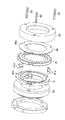
- FIG. FIG. 4 is an exploded view of the sealing device of the ball screw device according to the present embodiment
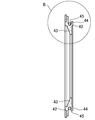
- FIG. 4 is a front view of a sealing member used in the ball screw device according to the present embodiment
- FIG. 6 is a cross-sectional view of A
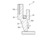
- FIG. 6 is an enlarged view of a portion B in FIG. 5
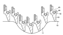
- FIG. 7 is a state diagram showing a state where the seal member is in contact with the screw shaft
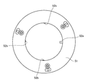
- FIG. FIG. 9 is a view showing the lubricating means of the screw device from the axial direction
- FIG. 9 is a view for explaining the contact state of the seal member used in the embodiment of the ball screw device according to the present invention.
- FIG. 1 shows a ball screw device 1 according to this embodiment.
- the ball screw device 1 includes a screw shaft 10 as a shaft member in which a spiral rolling element rolling groove 11 is formed with a predetermined lead on an outer peripheral surface, and a screw shaft via a plurality of rolling elements 30. 10 and a nut 20 as a moving member having an infinite circulation path (not shown) of the rolling element 30, and the nut 20 is rotated by relative rotation between the screw shaft 10 and the nut 20. 20 is configured to move in the axial direction of the screw shaft 10.
- the rolling element rolling groove 11 is subjected to surface processing with an accuracy such that smooth rolling of the rolling element 30 can be realized.
- the shape of a rolling surface it may be a Gothic arch shape or a circular arc shape.
- the nut 20 is formed with a load rolling element rolling groove 22 opposed to the rolling element rolling groove 11 on the inner peripheral surface, and a nut body 21 having a substantially cylindrical shape, and a rolling element rolling groove.
- Lubricating means 50 for applying a lubricant to the outer circumferential surface of the running groove 11 and the screw shaft 10 is provided.
- a plurality of rolling elements 30 are arranged between the rolling element rolling grooves 11 and the load rolling element rolling grooves 22, and the nut 20 is interposed via the rolling elements 30 with respect to the screw shaft 10. Are assembled.
- a sealing device 40 that seals the inside and the outside of the nut 20 is attached to the end of the nut 20 in the axial direction.
- the sealing device 40 includes a substantially annular main body 42 assembled to the nut 20 via the lubrication means 50, and the inner periphery of the main body 42 so as to contact the outer peripheral surface of the screw shaft 10 and the rolling element rolling groove 11.
- a pair of seal members 41 each having a lip portion 43 extending obliquely from the surface toward the inside in the radial direction are assembled adjacent to each other.
- the lip 43 has a function of scraping off dust and the like adhering to the outer peripheral surface of the screw shaft 10 and the rolling element rolling groove 11.
- the pair of seal members 41, 41 are adjacent to each other so that the back surfaces thereof are aligned with each other, and the lip portion 43 extends in a direction away from the contact surface of the adjacent main body portion 42, and is arranged in a substantially C-shaped cross section. Has been.
- a plate member 48 having an axial projection shape substantially the same as that of the seal member 41 is attached to the end portion of the seal member 41.
- the plate member 48 is an annular member assembled so as to hold the seal member 41 in the axial direction, and its inner peripheral surface is predetermined from the outer peripheral surface of the screw shaft 10 and the rolling surface of the rolling element rolling groove 11. It is assembled with a gap.
- the inner peripheral surface acts as a scraper portion 48a that seals dust or the like larger than a predetermined gap.
- the pair of seal members 41 and 41 are assembled to the end portion of the lubrication means 50 via a collar 41a.
- the collar 41a is a member into which a bolt 60 described later is inserted, and positions the seal members 41 and 41.
- the sealing device 40 is configured by covering the case 49 with the outermost periphery and the outermost end in a state where the pair of sealing members 41 and 41 and the plate member 48 are arranged in this order, and fastening with the bolt 60. Is configured.
- the seal member 41 will be described in detail with reference to FIGS.
- the main body 42 is formed in a substantially annular shape.
- the lip 43 is formed to protrude from the inner peripheral surface of the main body 42 toward the inner diameter direction.
- the lip portion 43 is formed in a tongue-like shape in cross section and means a portion where sliding contact with the screw shaft 10 is made.
- the sealing member 41 has an urging means 44 assembled in a groove 45 formed in the main body 42.
- the biasing means 44 uses an annular coil spring as a spring member.
- a reinforcing portion 42 a that reinforces the main body portion 42 is attached to an end portion in the axial direction of the main body portion 42 on the slope 43 a side.
- the reinforcing part 42a is preferably formed of an annular metal plate.
- the lip portion 43 has an axial cross-sectional shape that is formed on a slope 43a whose one end surface is inclined with respect to the axial direction, and an opposite surface of the slope 43a is formed on a vertical surface 43b that intersects the axial direction substantially perpendicularly. ing.
- a connecting portion that is continuous with the main body portion 42 of the inclined surface 43a is formed with a thin deformed portion 42b.
- the tip end position of the lip portion 43 is shifted to the vertical surface 43b side with respect to the groove portion 45 to which the urging means 44 is attached. That is, the center C1 of the urging means 44 is separated from the tip C2 of the lip portion 43 along the axial direction, the tip of the lip portion 43 is on the vertical surface 43b side, and the center C1 of the urging means 44 is the inclined surface. It is arranged on the 43a side.
- biasing means 44 is arrange
- the lip portion 43 includes an arc portion 46 whose inner peripheral shape is an arc shape and a bulging portion 47 bulging from the arc shape in the inner diameter direction.
- the arc portion 46 is in contact with the outer peripheral surface of the screw shaft 10 to seal the outer peripheral surface of the screw shaft 10, and the bulging portion 47 is in contact with the rolling surface of the rolling element rolling groove 11 to roll. It acts to seal the rolling surface of the moving body rolling groove 11.
- the sealing member 41 is in contact with the urging means 44 with a certain pressure applied in the direction of the screw shaft 10, as shown in FIG. 7, the outer peripheral surface of the screw shaft 10 and the rolling element rolling. Any of the rolling surfaces of the groove 11 can be contacted at a constant pressure. Further, since the tip shape of the lip portion 43 is formed in an R shape, the lip portion 43 can be flexibly contacted even at a location where the rolling surface of the rolling element rolling groove 11 and the outer peripheral surface of the screw shaft 10 are continuous.
- the seal member 41 is formed of a flexible member so that a constant pressure can be applied to the screw shaft 10, and is formed of rubber, for example.
- the rubber hydrogenated acrylonitrile / butadiene rubber (H-NBR) excellent in heat resistance, oil resistance and abrasion resistance is preferably used.
- the seal member 41 is formed by the slope 43a and the vertical surface 43b whose axial cross-sectional shape is inclined with respect to the axial direction, and therefore the rigidity on the vertical surface 43b side is the slope 43a. It is formed higher than the side rigidity. Furthermore, since the tip of the lip portion 43 is formed on the vertical surface 43b side with respect to the center of the biasing means 44, the tip of the lip is perpendicular to the lip portion 43 along the deformation direction D by the biasing force of the biasing means 44. The lip portion 43 can be deformed so as to be bent toward the surface 43b, and can be brought into contact with the outer peripheral surface of the screw shaft 10 and the rolling surface of the rolling element rolling groove 11.
- the seal member 41 includes a reinforcing portion 42a on the inclined surface 43a side to improve the rigidity of the inclined surface 43a side of the main body portion 42, and a deformed portion 42b is formed at a connecting portion between the inclined surface 43a and the main body portion 42. Since the rigidity of the lip portion 43 on the slope 43a side is lowered, the deformation along the deformation direction D can be further promoted.
- the seal member 41 is deformed in a certain direction along the deformation direction D in a state where the lip portion 43 is in contact with the outer peripheral surface of the screw shaft 10 and the rolling surface of the rolling element rolling groove 11. If the deformation direction D is arranged so as to oppose the intrusion direction of dust or the like or the leakage direction of the lubricant, the sealing performance can be easily improved.
- the lubrication means 50 includes a lubricant holding portion 51 that holds lubricant applied to the rolling surface of the rolling element rolling groove 11 and the outer peripheral surface of the screw shaft 10, and the outer periphery of the rolling element rolling groove 11 and the screw shaft 10.
- a lubricant supply unit 52 is provided that slides on the surface and applies the lubricant to the rolling element rolling groove 11 and the outer peripheral surface of the screw shaft 10.
- the lubricant holding part 51 has a storage body 51a for storing the lubricant therein, and the storage body 51a is made of felt, for example.
- the felt of the storage body 51a is made of a material that can appropriately store the lubricant, and for example, rayon + wool felt having a porosity of about 80% is used.
- the lubricant supply unit 52 is made of felt having a certain thickness in contact with the storage body 51a, and the porosity of the felt of the lubricant supply unit 52 is set lower than the porosity of the storage body 51a.
- a wool felt having a porosity of about 50% is used for the felt of the lubricant supply unit 52.
- a plurality of lubricant supply parts 52 are formed so as to protrude from the lubricant holding part 51 in the inner peripheral direction of the nut 20.
- the plurality of lubricant supply units 52 include a first lubricant supply unit 52a having a large protruding amount and a second lubricant supply unit 52b having a small protruding amount.
- the first lubricant supply unit 52 a contacts the rolling surface of the rolling element rolling groove 11, and the second lubricant supply unit 52 b contacts the outer peripheral surface of the screw shaft 10.
- the lubrication means 50 can apply the lubricant to the outer circumferential surfaces of the rolling element rolling groove 11 and the screw shaft 10 by contacting the outer rolling surfaces of the rolling element rolling groove 11 and the screw shaft 10. .
- the lubricant applied to the rolling element rolling grooves 11 contributes to the smooth rolling of the rolling element
- the lubricant applied to the outer peripheral surface of the screw shaft 10 includes the outer peripheral surface of the screw shaft 10 and the lip portion 43.
- the lip portion 43 can be protected from wear caused by sliding contact.
- the lip portion 43 includes the inclined surface 43a inclined with respect to the axial direction, the reinforcing portion 42a is provided on the opposite surface of the inclined surface 43a, and the urging means 44 is provided. Since the center C1 of the lip portion 43 is positioned on the reinforcing portion side of the tip of the lip portion 43, the lip portion 43 of the seal member 41 is in contact with the outer peripheral surface of the screw shaft 10 and the rolling surface of the rolling element rolling groove 11. In the state, it can be deformed in a certain direction along the deformation direction D, and if the deformation direction D is arranged so as to face the intrusion direction of dust or the scattering direction of the grease, the sealing performance can be easily improved. Can do.
- the other end surface of the lip portion 43 is formed on a vertical surface 43b that intersects substantially perpendicularly with the axial direction, the rigidity of the lip portion 43 on the vertical surface 43b side can be improved.
- the outer peripheral surface of 10 and the rolling surface of the rolling element rolling groove 11 are in contact with each other, it can be urged to always be deformed in a certain direction along the deformation direction D.
- the lip portion 43 is formed on the outer peripheral surface of the screw shaft 10 and the rolling element rolling groove 11. In the state where it contacts the rolling surface, it can be urged to always deform along the deformation direction D in a certain direction.
- a pair of seal members 41 are used, and the lip portions 43 are arranged so as to extend away from the contact surfaces of the adjacent main body portions 42, thereby preventing intrusion of dust and the like and scattering of grease. It is possible to achieve a highly dustproof seal capable of achieving both prevention.
- the urging means 44 is configured as a spring member assembled in the groove portion 45 formed in the main body portion 42 of the seal member 41, a highly dustproof seal can be achieved with a simple configuration.
- the lip portion 43 includes an arc portion that contacts the outer peripheral surface of the screw shaft 10 and a bulging portion that contacts the rolling surface of the rolling element rolling groove 11, the outer peripheral surface of the screw shaft 10 and the rolling element rolling portion are provided. Both rolling surfaces of the running groove 11 can be reliably sealed. Moreover, since it arrange
- the arranged sealing member 41 can prevent the grease and the like from scattering from the inside of the nut 20, and the sealing member 41 arranged on the outside can prevent dust and the like from entering from the outside of the nut 20.
- a plate member 48 having a scraper portion 48a arranged at a predetermined gap with respect to the outer peripheral surface of the screw shaft 10 and the rolling surface of the rolling element rolling groove 11 is provided at the end of the sealing device 40. Since it is provided, dust or the like larger than the predetermined gap can be prevented from entering by the scraper portion 48a.
- the nut 20 is provided with the lubrication means 50 which apply
- the lip portion 43 can be protected from wear caused by the sliding contact between the outer peripheral surface of the screw shaft 10 and the lip portion 43.
- the foreign matter intrusion amount, sealing performance, and heat generation amount of the ball screw device according to this embodiment and the ball screw device provided with the conventional sealing member were measured.
- Conventional seal members were measured for two types, a non-contact type and a contact type.
- the ball screw device according to the present embodiment has a result that the foreign matter concentration is 0.017 to 0.034% Wt, and the conventional non-contact type seal member has 0.175 to 0.278% Wt. In the conventional contact-type seal member, a result of 0.145 to 0.205% Wt was obtained. As described above, the ball screw device according to the present embodiment greatly prevents the intrusion of foreign matters as compared with the conventional seal member, and has a high dustproof performance against dust having a particle size of several tens of ⁇ m. As a result.
- Sealing performance is measured by enclosing a certain amount of grease inside the nut, continuously reciprocating the nut, and then measuring the amount of grease adhering to the screw shaft. The amount of was measured.
- the ball screw device according to the present embodiment has a result that the amount of grease scattering is 0.23 to 0.36 g, and the conventional non-contact type seal member is 2.34 to 3.28 g. With the contact-type seal member, a result of 0.50 to 0.55 g was obtained. As described above, the ball screw device according to this embodiment has a result that the amount of grease scattered is small and the sealing performance in the nut is high as compared with the conventional seal member.
- Measured calorific value was obtained by continuously reciprocating the nut and measuring the temperature of the outer surface of the nut and the outer surface of the screw shaft every 30 minutes. Moreover, the highest temperature was totaled among the measured temperatures, and the increase amount was compared.
- the ball screw device 1 according to the present embodiment has an increase in heat generation of 3.2 ° C. on the nut side / 5.2 ° C. on the screw shaft side.
- the result was 10.0 ° C. on the side / 9.3 ° C. on the screw shaft side, and 20 ° C. on the nut side / 28.7 ° C. on the screw shaft side with the conventional contact seal member.
- the ball screw device according to the present embodiment shows a significantly lower value than the conventional non-contact type and contact type seal members, and the heat generation amount is very small.
- the present invention is not limited to the above-described embodiment, and various modifications can be made without departing from the scope of the present invention.
- a ball screw device has been described, but the present invention may be applied to a linear motion guide device such as a ball spline.
- the ball spline is formed in a substantially cylindrical shape having a spline shaft as a race member in which a plurality of rolling element rolling portions are formed along the longitudinal direction, and a hollow hole through which the spline shaft passes, It is comprised from the spline nut as a moving member attached to the spline shaft via the some rolling element.
- the spline nut has the same number of endless circulation paths as the rolling element rolling parts, and the rolling elements that have run through the rolling part rolling part of the spline shaft circulate through the infinite circulation path formed in the spline nut. As a result, the spline nut can freely reciprocate linearly along the spline shaft.
- the rolling element may be a cylindrical roller. It is apparent from the scope of the claims that the embodiments added with such changes or improvements can be included in the technical scope of the present invention.
Landscapes
- Engineering & Computer Science (AREA)
- General Engineering & Computer Science (AREA)
- Mechanical Engineering (AREA)
- Transmission Devices (AREA)
Abstract
Description
Claims (6)
- 軸部材と移動部材との間に転がり運動可能に複数の転動体を介在させた直線運動案内装置における前記移動部材の軸方向の端面に取り付けられるシール部材において、
前記シール部材は、前記移動部材に取り付けられる本体部と、前記軸部材の外周に接触するリップ部とを有し、
前記リップ部は、軸方向の断面形状が前記軸方向に対して傾斜した斜面を備え、
前記本体部は、前記リップ部を前記軸部材の径方向に付勢する付勢手段を備えると共に、前記斜面側に、前記本体部を補強する補強部を備え、
前記リップ部の軸方向の断面形状において、前記付勢手段は、前記リップ部の先端よりも前記補強部側に位置していることを特徴とするシール部材。 - 請求項1に記載のシール部材において、
前記リップ部の前記斜面の反対面は前記軸方向と略垂直に交わる垂直面に形成されることを特徴とするシール部材。 - 請求項1または2に記載のシール部材において、
前記斜面と前記本体部の連結部は、変形部が形成されることを特徴とするシール部材。 - 請求項1から3のいずれか1項に記載のシール部材において、
前記シール部材は一対形成され、
前記リップ部は互いに隣接する前記シール部材の前記本体部の当接面から互いに離間する方向に延びることを特徴とするシール部材。 - 請求項1から4のいずれか1項に記載のシール部材において、
前記移動部材は、潤滑剤を保持する潤滑剤保持部と、前記軸部材に形成された転動体転走溝および前記軸部材の外周面に摺接して前記潤滑剤を前記転動体転走溝および前記ねじ軸の外周面に塗布する複数の潤滑剤供給部とを備えた潤滑手段を有することを特徴とするシール部材。 - 外周面に螺旋状の転動体転走溝を有するねじ軸と、
内周面に前記転動体転走溝に対向する負荷転動体転走溝を有するナットと、
前記転動体転走溝と、前記負荷転動体転走溝との間に転がり運動可能に配列される複数の転動体と、
前記ナットの少なくとも一端に取り付けられるシール装置を備えるボールねじ装置において、
前記シール装置は、前記ナットに取り付けられる本体部と、前記ねじ軸の外周または前記転動体転走溝に接触するリップ部とを有するシール部材を備え、
前記リップ部は、軸方向の断面形状が前記軸方向に対して傾斜した斜面を備え、
前記本体部は、前記リップ部を前記ねじ軸の径方向に付勢する付勢手段を備えると共に、前記斜面側に、前記本体部を補強する補強部を備え、
前記リップ部の軸方向の断面形状において、前記付勢手段は、前記リップ部の先端よりも前記補強部側に位置していることを特徴とするボールねじ装置。
Priority Applications (3)
| Application Number | Priority Date | Filing Date | Title |
|---|---|---|---|
| US13/988,610 US9506544B2 (en) | 2010-12-20 | 2011-12-09 | Seal member and linear motion guide device using same |
| CN201180061001.1A CN103261742B (zh) | 2010-12-20 | 2011-12-09 | 密封构件及使用该密封构件的直线运动引导装置 |
| DE112011104453.4T DE112011104453B4 (de) | 2010-12-20 | 2011-12-09 | Dichtungselement und linearbewegungsführungsvorrichtung unter verwendung desselben |
Applications Claiming Priority (4)
| Application Number | Priority Date | Filing Date | Title |
|---|---|---|---|
| JP2010-283522 | 2010-12-20 | ||
| JP2010283522 | 2010-12-20 | ||
| JP2011-267221 | 2011-12-06 | ||
| JP2011267221A JP5192074B2 (ja) | 2010-12-20 | 2011-12-06 | シール部材及びこれを用いた直線運動案内装置 |
Publications (1)
| Publication Number | Publication Date |
|---|---|
| WO2012086432A1 true WO2012086432A1 (ja) | 2012-06-28 |
Family
ID=46313712
Family Applications (1)
| Application Number | Title | Priority Date | Filing Date |
|---|---|---|---|
| PCT/JP2011/078509 Ceased WO2012086432A1 (ja) | 2010-12-20 | 2011-12-09 | シール部材及びこれを用いた直線運動案内装置 |
Country Status (6)
| Country | Link |
|---|---|
| US (1) | US9506544B2 (ja) |
| JP (1) | JP5192074B2 (ja) |
| CN (1) | CN103261742B (ja) |
| DE (1) | DE112011104453B4 (ja) |
| TW (1) | TWI568956B (ja) |
| WO (1) | WO2012086432A1 (ja) |
Cited By (1)
| Publication number | Priority date | Publication date | Assignee | Title |
|---|---|---|---|---|
| TWI476332B (zh) * | 2012-12-27 | 2015-03-11 | Hiwin Tech Corp | 具有可替換配件的防塵模組之滾珠螺桿 |
Families Citing this family (11)
| Publication number | Priority date | Publication date | Assignee | Title |
|---|---|---|---|---|
| US20150122065A1 (en) * | 2012-05-10 | 2015-05-07 | Nsk Ltd | Ball Screw Device |
| US10612634B2 (en) * | 2016-03-18 | 2020-04-07 | Hiwin Technologies Corp. | Dustproof device for ball screw |
| JP6400176B2 (ja) * | 2017-01-12 | 2018-10-03 | Thk株式会社 | ボールねじ装置のシール部材 |
| EP3392526B1 (en) * | 2017-04-21 | 2020-08-26 | Goodrich Actuation Systems Limited | Hybrid ballscrew seal |
| CN109268463B (zh) | 2017-07-18 | 2020-07-17 | 上银科技股份有限公司 | 具防尘元件的滚珠螺杆 |
| BR112020007057B1 (pt) * | 2017-10-19 | 2022-07-12 | Jfe Steel Corporation | Placa de aço de alta resistência para tubos em linha resistentes a ácidos e tubo de aço de alta resistência que usa a mesma |
| JP6977643B2 (ja) * | 2018-03-26 | 2021-12-08 | 株式会社デンソー | ボールねじ装置の異常検出装置 |
| CN111609103A (zh) * | 2020-05-11 | 2020-09-01 | 宁波海迈克精密机械制造有限公司 | 一种滚珠丝杠副 |
| CN112460218A (zh) * | 2020-11-27 | 2021-03-09 | 西安理工大学 | 一种接触式滚珠丝杠的密封装置 |
| JP7738438B2 (ja) | 2021-09-28 | 2025-09-12 | Ntn株式会社 | 送りねじ機構及び電動アクチュエータ |
| US12523302B2 (en) * | 2023-01-25 | 2026-01-13 | Trelleborg Sealing Solutions Us, Inc. | Wiper seal for a ball screw actuator |
Citations (6)
| Publication number | Priority date | Publication date | Assignee | Title |
|---|---|---|---|---|
| JPS60107457U (ja) * | 1983-12-26 | 1985-07-22 | エヌオーケー株式会社 | オイルシ−ル |
| JPS60107458U (ja) * | 1983-12-26 | 1985-07-22 | エヌオーケー株式会社 | オイルシ−ル |
| JPH10184683A (ja) * | 1996-11-11 | 1998-07-14 | Thk Kk | 直線運動装置及びこれに使用される潤滑油供給装置 |
| JPH10299854A (ja) * | 1997-04-23 | 1998-11-13 | Amada Co Ltd | ボールねじのシール |
| JP2006300192A (ja) * | 2005-04-20 | 2006-11-02 | Tsubaki Nakashima Co Ltd | グリース潤滑ボールねじ |
| JP2010139043A (ja) * | 2008-12-15 | 2010-06-24 | Toyota Motor Corp | オイルシール |
Family Cites Families (17)
| Publication number | Priority date | Publication date | Assignee | Title |
|---|---|---|---|---|
| US2818745A (en) * | 1955-02-11 | 1958-01-07 | Cleveland Pneumatic Tool Co | Screw cleaning device |
| DE2909508A1 (de) * | 1979-03-10 | 1980-09-18 | Skf Kugellagerfabriken Gmbh | Waelzlager fuer laengsbewegungen |
| DE3041804A1 (de) * | 1980-11-06 | 1982-06-03 | Skf Kugellagerfabriken Gmbh | Waelzlager fuer die laengsfuehrung einer welle o.dgl. |
| DE3641682A1 (de) * | 1986-12-08 | 1988-06-16 | Kugelfischer G Schaefer & Co | Dichtung fuer einen kugelgewindetrieb |
| TW356507B (en) | 1996-11-11 | 1999-04-21 | Thk Corp | A linear motion device and the grease supply device that used in the device |
| JP3560831B2 (ja) * | 1998-10-28 | 2004-09-02 | 株式会社名機製作所 | 真空式ホットプレス装置のシャッタのシール構造 |
| JP3367911B2 (ja) * | 1999-02-26 | 2003-01-20 | Thk株式会社 | 潤滑油供給装置及びこれを用いた転動体ねじ装置 |
| JP3454502B2 (ja) * | 2000-03-15 | 2003-10-06 | Thk株式会社 | 潤滑油供給装置及びこれを用いた転動体ねじ装置 |
| JP4507368B2 (ja) * | 2000-08-25 | 2010-07-21 | 日本精工株式会社 | ボールねじ用シール、ボールねじ |
| JP4608079B2 (ja) * | 2000-11-24 | 2011-01-05 | Thk株式会社 | ワイパーリング及びこれを組み込んだボールねじ |
| JP2002181201A (ja) * | 2000-12-15 | 2002-06-26 | Nsk Ltd | シール装置 |
| JP2002364726A (ja) | 2001-04-05 | 2002-12-18 | Thk Co Ltd | ボールねじ用シール及びこのボールねじ用シールを用いたボールねじ |
| JP2005221020A (ja) * | 2004-02-06 | 2005-08-18 | Nok Corp | 密封装置 |
| WO2007108018A1 (en) * | 2006-03-20 | 2007-09-27 | Aktiebolaget Skf | Annular sealing assembly, in particular for wheel hubs |
| US8511896B2 (en) * | 2007-09-28 | 2013-08-20 | Thk Co., Ltd. | Rolling device |
| JP5071403B2 (ja) | 2009-02-12 | 2012-11-14 | 日本精工株式会社 | ボールねじ |
| US8336416B2 (en) * | 2009-12-30 | 2012-12-25 | Hiwin Technologies Corp. | Ball screw device having cooling structure |
-
2011
- 2011-12-06 JP JP2011267221A patent/JP5192074B2/ja active Active
- 2011-12-09 DE DE112011104453.4T patent/DE112011104453B4/de active Active
- 2011-12-09 CN CN201180061001.1A patent/CN103261742B/zh active Active
- 2011-12-09 US US13/988,610 patent/US9506544B2/en active Active
- 2011-12-09 WO PCT/JP2011/078509 patent/WO2012086432A1/ja not_active Ceased
- 2011-12-19 TW TW100147119A patent/TWI568956B/zh active
Patent Citations (6)
| Publication number | Priority date | Publication date | Assignee | Title |
|---|---|---|---|---|
| JPS60107457U (ja) * | 1983-12-26 | 1985-07-22 | エヌオーケー株式会社 | オイルシ−ル |
| JPS60107458U (ja) * | 1983-12-26 | 1985-07-22 | エヌオーケー株式会社 | オイルシ−ル |
| JPH10184683A (ja) * | 1996-11-11 | 1998-07-14 | Thk Kk | 直線運動装置及びこれに使用される潤滑油供給装置 |
| JPH10299854A (ja) * | 1997-04-23 | 1998-11-13 | Amada Co Ltd | ボールねじのシール |
| JP2006300192A (ja) * | 2005-04-20 | 2006-11-02 | Tsubaki Nakashima Co Ltd | グリース潤滑ボールねじ |
| JP2010139043A (ja) * | 2008-12-15 | 2010-06-24 | Toyota Motor Corp | オイルシール |
Cited By (1)
| Publication number | Priority date | Publication date | Assignee | Title |
|---|---|---|---|---|
| TWI476332B (zh) * | 2012-12-27 | 2015-03-11 | Hiwin Tech Corp | 具有可替換配件的防塵模組之滾珠螺桿 |
Also Published As
| Publication number | Publication date |
|---|---|
| CN103261742A (zh) | 2013-08-21 |
| TWI568956B (zh) | 2017-02-01 |
| TW201243186A (en) | 2012-11-01 |
| JP5192074B2 (ja) | 2013-05-08 |
| US20130255419A1 (en) | 2013-10-03 |
| DE112011104453T5 (de) | 2013-09-19 |
| JP2012145221A (ja) | 2012-08-02 |
| DE112011104453B4 (de) | 2023-10-12 |
| US9506544B2 (en) | 2016-11-29 |
| CN103261742B (zh) | 2016-10-26 |
Similar Documents
| Publication | Publication Date | Title |
|---|---|---|
| JP5192074B2 (ja) | シール部材及びこれを用いた直線運動案内装置 | |
| WO2009150935A1 (ja) | 保持器、深溝玉軸受、およびシール付軸受 | |
| WO2012029232A1 (ja) | 直動案内装置 | |
| US6817769B2 (en) | Roller bearing having high performance bearing seal and cartridge | |
| JP5463687B2 (ja) | 転がり軸受 | |
| WO2008050759A1 (en) | Sealing device and rolling bearing device | |
| KR102473317B1 (ko) | 밀봉 장치 및 이것을 구비한 베어링 장치 | |
| JP5835199B2 (ja) | 玉軸受 | |
| WO2016125516A1 (ja) | 鉄道車両用軸受装置 | |
| JPH10196664A (ja) | 転がり軸受の密封装置 | |
| JP2006300192A (ja) | グリース潤滑ボールねじ | |
| JP2005337407A (ja) | 直動案内軸受装置 | |
| JP2007051761A (ja) | 転がり軸受のシール構造 | |
| WO2016147881A1 (ja) | 保持器および転がり軸受 | |
| US20030047879A1 (en) | Rotary sealing device | |
| US20170175897A1 (en) | Seal assembly | |
| JP2019168020A (ja) | 円筒ころ軸受 | |
| JP4915346B2 (ja) | 固体潤滑ころ軸受 | |
| JPH084773A (ja) | 固体潤滑転がり軸受 | |
| JP2006317006A (ja) | 直動案内軸受装置用防塵構造 | |
| JP2006038035A (ja) | 直動案内軸受装置 | |
| JP2018004062A (ja) | 転がり軸受 | |
| JP2018168871A (ja) | フォロア軸受 | |
| JPH018736Y2 (ja) | ||
| JP2019157884A (ja) | オイルシール及びシール付軸受 |
Legal Events
| Date | Code | Title | Description |
|---|---|---|---|
| 121 | Ep: the epo has been informed by wipo that ep was designated in this application |
Ref document number: 11850755 Country of ref document: EP Kind code of ref document: A1 |
|
| WWE | Wipo information: entry into national phase |
Ref document number: 13988610 Country of ref document: US |
|
| WWE | Wipo information: entry into national phase |
Ref document number: 112011104453 Country of ref document: DE Ref document number: 1120111044534 Country of ref document: DE |
|
| 122 | Ep: pct application non-entry in european phase |
Ref document number: 11850755 Country of ref document: EP Kind code of ref document: A1 |