WO2012073943A1 - 表示装置及びテレビ受像機 - Google Patents
表示装置及びテレビ受像機 Download PDFInfo
- Publication number
- WO2012073943A1 WO2012073943A1 PCT/JP2011/077494 JP2011077494W WO2012073943A1 WO 2012073943 A1 WO2012073943 A1 WO 2012073943A1 JP 2011077494 W JP2011077494 W JP 2011077494W WO 2012073943 A1 WO2012073943 A1 WO 2012073943A1
- Authority
- WO
- WIPO (PCT)
- Prior art keywords
- panel module
- display device
- fixing member
- shaped fixing
- flexible claw
- Prior art date
Links
Images


Classifications
-
- G—PHYSICS
- G02—OPTICS
- G02F—OPTICAL DEVICES OR ARRANGEMENTS FOR THE CONTROL OF LIGHT BY MODIFICATION OF THE OPTICAL PROPERTIES OF THE MEDIA OF THE ELEMENTS INVOLVED THEREIN; NON-LINEAR OPTICS; FREQUENCY-CHANGING OF LIGHT; OPTICAL LOGIC ELEMENTS; OPTICAL ANALOGUE/DIGITAL CONVERTERS
- G02F1/00—Devices or arrangements for the control of the intensity, colour, phase, polarisation or direction of light arriving from an independent light source, e.g. switching, gating or modulating; Non-linear optics
- G02F1/01—Devices or arrangements for the control of the intensity, colour, phase, polarisation or direction of light arriving from an independent light source, e.g. switching, gating or modulating; Non-linear optics for the control of the intensity, phase, polarisation or colour
- G02F1/13—Devices or arrangements for the control of the intensity, colour, phase, polarisation or direction of light arriving from an independent light source, e.g. switching, gating or modulating; Non-linear optics for the control of the intensity, phase, polarisation or colour based on liquid crystals, e.g. single liquid crystal display cells
- G02F1/133—Constructional arrangements; Operation of liquid crystal cells; Circuit arrangements
- G02F1/1333—Constructional arrangements; Manufacturing methods
- G02F1/133308—Support structures for LCD panels, e.g. frames or bezels
-
- H—ELECTRICITY
- H05—ELECTRIC TECHNIQUES NOT OTHERWISE PROVIDED FOR
- H05K—PRINTED CIRCUITS; CASINGS OR CONSTRUCTIONAL DETAILS OF ELECTRIC APPARATUS; MANUFACTURE OF ASSEMBLAGES OF ELECTRICAL COMPONENTS
- H05K5/00—Casings, cabinets or drawers for electric apparatus
- H05K5/02—Details
- H05K5/0217—Mechanical details of casings
- H05K5/0221—Locks; Latches
-
- H—ELECTRICITY
- H04—ELECTRIC COMMUNICATION TECHNIQUE
- H04N—PICTORIAL COMMUNICATION, e.g. TELEVISION
- H04N5/00—Details of television systems
- H04N5/64—Constructional details of receivers, e.g. cabinets or dust covers
-
- G—PHYSICS
- G02—OPTICS
- G02F—OPTICAL DEVICES OR ARRANGEMENTS FOR THE CONTROL OF LIGHT BY MODIFICATION OF THE OPTICAL PROPERTIES OF THE MEDIA OF THE ELEMENTS INVOLVED THEREIN; NON-LINEAR OPTICS; FREQUENCY-CHANGING OF LIGHT; OPTICAL LOGIC ELEMENTS; OPTICAL ANALOGUE/DIGITAL CONVERTERS
- G02F1/00—Devices or arrangements for the control of the intensity, colour, phase, polarisation or direction of light arriving from an independent light source, e.g. switching, gating or modulating; Non-linear optics
- G02F1/01—Devices or arrangements for the control of the intensity, colour, phase, polarisation or direction of light arriving from an independent light source, e.g. switching, gating or modulating; Non-linear optics for the control of the intensity, phase, polarisation or colour
- G02F1/13—Devices or arrangements for the control of the intensity, colour, phase, polarisation or direction of light arriving from an independent light source, e.g. switching, gating or modulating; Non-linear optics for the control of the intensity, phase, polarisation or colour based on liquid crystals, e.g. single liquid crystal display cells
- G02F1/1306—Details
- G02F1/1309—Repairing; Testing
-
- G—PHYSICS
- G02—OPTICS
- G02F—OPTICAL DEVICES OR ARRANGEMENTS FOR THE CONTROL OF LIGHT BY MODIFICATION OF THE OPTICAL PROPERTIES OF THE MEDIA OF THE ELEMENTS INVOLVED THEREIN; NON-LINEAR OPTICS; FREQUENCY-CHANGING OF LIGHT; OPTICAL LOGIC ELEMENTS; OPTICAL ANALOGUE/DIGITAL CONVERTERS
- G02F2201/00—Constructional arrangements not provided for in groups G02F1/00 - G02F7/00
- G02F2201/46—Fixing elements
- G02F2201/465—Snap -fit
Definitions
- the present invention relates to a display device and a television receiver including a panel module having a display surface on the front side, a front cabinet that surrounds the peripheral portion of the panel module, and a back cabinet that covers the rear side of the panel module.
- a display device such as a television receiver includes a panel module having a display surface for displaying images on the front side, a front cabinet that surrounds the peripheral edge of the panel module, and a back cabinet that covers the rear side of the panel module.
- the panel module and the front cabinet are fixed using screws, and an increase in the number of assembly work has been a problem.
- Patent Document 1 discloses a display device that solves the above-described problems.
- the display device according to Patent Literature 1 includes a plurality of flexible claw hooks protruding rearward from the outer peripheral portion of the front cabinet, and the front cabinet is fixed to the panel module by the claw hooks.
- the display device according to Patent Document 1 has a problem that it is difficult to remove the front cabinet from the panel module during maintenance. Specifically, when removing the panel module from the front cabinet, it is necessary to remove the claw hooks that are hooked around the panel module in order. I was often caught. For this reason, the panel module is removed by a plurality of workers, or a member such as a wedge is sandwiched between the hook claw and the panel module so that the hook claw once removed is not caught on the panel module again. There was a need. This problem is particularly remarkable when the display device is enlarged, and the maintainability is deteriorated.
- the present invention has been made in view of such circumstances, and an object of the present invention is to fix the panel module to the front cabinet without using screws, and to perform the maintenance from the front cabinet to the panel module. It is an object of the present invention to provide a display device and a television receiver that can be easily detached.
- the display device includes a panel module having a display surface on a front side, a front cabinet that surrounds a peripheral portion of the panel module, and a back cabinet that covers a rear side of the panel module.
- a flexible claw projecting from the inner surface of the cabinet to the back cabinet side, an L-shaped retaining plate having a hole for retaining the flexible claw, and a rear surface of the panel module.
- An L-shaped fixing member that includes an abutting plate that contacts the front cabinet and fixes the front cabinet to the panel module is provided.
- the abutment plate of the L-shaped fixing member is brought into contact with the rear surface of the panel module, and the retaining plate of the L-shaped fixing member is hooked on the flexible claw portion of the front cabinet. It is possible to fix the front cabinet. Further, when performing maintenance, the panel module can be easily removed from the front cabinet by removing the L-shaped fixing member caught on the flexible claw portion. That is, the flexible claw part from which the L-shaped fixing member is removed is not caught by the panel module, and the panel module can be easily removed.
- the display device is characterized in that the back cabinet includes a restricting portion that restricts the flexible claw portion from being bent in a direction away from the hole portion of the retaining plate.
- the flexible claw part it is possible to restrict the flexible claw part from being bent in a direction away from the L-shaped fixing member by the restriction part provided in the back cabinet. Therefore, when the display device is used, the flexible claw portion is not detached from the L-shaped fixing member due to an impact, and the front cabinet is not dropped from the panel module.
- the display device is characterized in that the front cabinet includes a support member that supports the L-shaped fixing member on which the flexible claw portion is hooked.
- the L-shaped fixing member can be guided to the place where the flexible claw is caught and supported by the front cabinet.
- two support members are provided on both sides of the flexible nail portion along the panel module facing the flexible nail portion, and the flexible nail portion is provided.
- the positioning operation of the L-shaped fixing member with respect to the flexible claw portion and the operation of hooking the flexible claw portion to the hole portion of the L-shaped fixing member can be performed in stages. Become. Therefore, the mounting workability of the L-shaped fixing member is improved.
- the positioning protrusion moves in a direction along the peripheral edge of the panel module when the L-shaped fixing member is hooked on the flexible claw portion.
- the L-shaped fixing member is rotated in a state where the protruding piece of the L-shaped fixing member is in contact with the positioning protrusion, and the L flexible claw portion is hooked on the hole of the L-shaped fixing member. It is possible to make it.
- the contact plate includes a contact protrusion that contacts the rear surface of the panel module, and the contact protrusion and the portion on which the flexible claw is hooked are It is separated in the direction along the peripheral part of the panel module.
- the contact protrusion and the portion where the flexible claw is hooked are separated in the direction along the peripheral edge of the panel module. Even if fluctuates, a large force is not applied to the flexible claw portion. Therefore, the attachment workability of the L-shaped fixing member does not deteriorate. Further, the front cabinet is not deformed, and there is no possibility that the aesthetic appearance is impaired.
- the display device is provided on the inner side in the horizontal direction and the vertical direction with respect to the flexible claw portion of the front cabinet, and includes a contact member that contacts the outer peripheral surface of the panel module. To do.
- the contact member provided on the inner side in the horizontal direction and the vertical direction with respect to the flexible claw portion of the front cabinet contacts the outer peripheral surface of the panel module. Therefore, when the panel module is moved with respect to the front cabinet, the panel module is prevented from coming into direct contact with the flexible claw portion to cause unexpected stress. Therefore, it is possible to prevent the flexible claw portion from being broken.
- the display device is characterized in that the flexible claw portions are provided on both side portions and an upper inner surface of the front cabinet.
- flexible claws are provided on both sides and top of the front cabinet. That is, the flexible claw part is not provided in the lower part of the front cabinet. Therefore, the front cabinet can be attached to the panel module with the minimum number of flexible claws, and the display device can be configured at low cost.
- the front cabinet includes a frame plate portion that covers a peripheral edge on the display surface side of the panel module, and a front cylinder portion that extends backward from the outer peripheral edge of the frame plate portion and covers the outer periphery of the panel module.
- the flexible claw portion protrudes from the inner surface of the front tube portion, and is configured to bend in a direction in which the flexible claw portion is in contact with or separated from the panel module.
- the flexible claw portion bends in a direction in which it is in contact with or separated from the panel module, the flexible claw portion can be latched to the L-shaped fixing member even if there is a manufacturing error in the panel module.
- the position is changed and the flexible claw is hooked on the L-shaped fixing member.
- the L-shaped fixing member can always be brought into contact with the panel module regardless of the manufacturing error of the panel module, and the occurrence of chatter due to voice can be suppressed.
- the latching position of the flexible claw portion changes, even if there is a manufacturing error in the panel module, there is no need to strongly press the L-shaped fixing member to latch the flexible claw portion.
- the display device according to the present invention is characterized in that the contact plate is curved so that the panel module side is convex.
- the contact plate of the L-shaped fixing member since the contact plate of the L-shaped fixing member is convex on the panel module side, the contact plate makes line contact with the panel module. Even if the panel module has a manufacturing error and the posture of the L-shaped fixing member with respect to the panel module changes, the L-shaped fixing member makes line contact with the panel module. For this reason, the L-shaped fixing member can always be brought into contact with the panel module regardless of the manufacturing error of the panel module, and the occurrence of chatter due to voice can be suppressed.
- the display device is characterized in that a tip of the flexible claw portion is located on the rear side of the panel module.
- the tip of the flexible claw portion protrudes rearward from the panel module, the position of the flexible claw portion is easily visible when removing the front cabinet from the panel module during maintenance.
- the panel module includes a liquid crystal panel, a backlight device disposed on a rear surface side of the liquid crystal panel, and a holding frame that integrally holds the liquid crystal panel and the backlight device. It is characterized by providing.
- a panel module is formed by integrating the liquid crystal panel and the backlight device with the holding frame.
- a television receiver includes any one of the display devices described above and a receiving unit that receives a video signal, and the display device displays video using the video signal received by the receiving unit. It is characterized by being.
- the present invention it is possible to receive a video signal and display a video related to the video signal on a display device.
- the panel module can be fixed to the front cabinet without using screws, and the panel module can be easily removed from the front cabinet when performing maintenance.
- FIG. 1 It is an exploded perspective view of the front side which shows one structural example of the display apparatus which concerns on embodiment of this invention. It is an expanded sectional side view which shows the principal part of a display apparatus. It is a disassembled perspective view of the principal part which shows the L-shaped fixing member removed from the front cabinet. It is a disassembled perspective view of the principal part which shows the L-shaped fixing member attached to the front cabinet. It is a disassembled perspective view of the principal part of the back side which shows the state which attached the front cabinet to the panel module with the L-shaped fixing member. It is a rear view of a front cabinet. It is the rear view and side view which show the principal part of a front cabinet. It is a six-faced view of an L-shaped fixing member.
- FIG. 10 is an enlarged side cross-sectional view showing a main part of a display device according to Modification 2.
- FIG. 12 is an enlarged side cross-sectional view showing an operation of a display device according to Modification 2.
- FIG. 14 is an enlarged side cross-sectional view showing a main part of a display device according to Modification 3.
- FIG. 14 is an expanded side sectional view which shows the effect
- 14 is an enlarged side cross-sectional view showing a main part of a display device according to Modification 4.
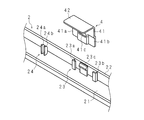
- FIG. 1 is an exploded perspective view of a front side showing a configuration example of a display device according to an embodiment of the present invention.
- the display device according to the present embodiment is a television receiver such as a liquid crystal television.
- the display device has a display surface 11a on the front side, a panel module 1 that forms a substantially rectangular parallelepiped, a front cabinet 2 that surrounds the periphery of the panel module 1, a back cabinet 3 that covers the rear side of the panel module 1, and a panel module.
- a metal L-shaped fixing member 4 for fixing the front cabinet 2 to 1, a tuner 5 (receiving unit) for receiving a video signal, an electric circuit 6, and a stand 7 for supporting the panel module 1 in an upright state. Is provided.
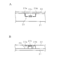
- FIG. 2 is an enlarged side cross-sectional view showing the main part of the display device
- FIG. 3 is an exploded perspective view of the main part showing the L-shaped fixing member 4 removed from the front cabinet 2
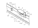
- FIG. 5 is an exploded perspective view of the main part on the back side showing a state in which the front cabinet 2 is attached to the panel module 1 by the L-shaped fixing member 4.
- 6 is a rear view of the front cabinet 2
- FIG. 7 is a rear view and a side view showing the main part of the front cabinet 2
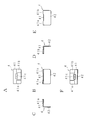
- FIG. 8 is a six-face view of the L-shaped fixing member 4.
- the panel module 1 includes a horizontally elongated liquid crystal panel 11 having a display surface 11a on the front side, an optical sheet (not shown) disposed on the rear surface side of the liquid crystal panel 11, and a backlight disposed on the rear surface side of the optical sheet.
- the device 12 includes a holding frame 13 that integrally holds the liquid crystal panel 11 and the backlight device 12.
- the backlight device 12 includes a flat dish-shaped backlight chassis, a reflective sheet disposed on the backlight chassis, and a plurality of light sources.
- the light source is, for example, an LED or a cold cathode fluorescent tube.
- the panel module 1 has a screw hole on the rear surface side for screwing the panel module 1 and the back cabinet 3 with screws.
- the tuner 5 and the electric circuit 6 are attached to the back side of the backlight chassis constituting the backlight device 12.
- the front cabinet 2 includes a frame plate portion 21 that covers the peripheral edge of the panel module 1 on the display surface 11 a side, and a front cylinder portion 22 that continues from the outer peripheral edge of the frame plate portion 21 to the rear and covers the outer periphery of the panel module 1. .
- a latching means 23 for latching the L-shaped fixing member 4 is provided on the rear surface of the frame plate portion 21, a latching means 23 for latching the L-shaped fixing member 4 is provided.
- a plurality of the latching means 23 are provided on each of the lateral side portions and the upper portion of the front cabinet 2. The number of the latching means 23 is appropriately determined depending on the size of the display device. As shown in FIG.
- the hooking means 23 includes a flexible claw portion 23c protruding from the rear surface of the frame plate portion 21 toward the back cabinet 3, and an L-shaped fixing member 4 on which the flexible claw portion 23c is hooked.
- the flexible claw portion 23c has a plate shape having a hook-shaped portion at the tip portion, and has a linear shape along the peripheral edge of the frame plate portion 21 in a rear view as shown in FIG. 7A.
- the bowl-shaped part has an inclined surface on the inner side in the in-plane direction of the display surface 11a, and the outer side in the in-plane direction of the bowl-shaped part is flat.
- the support members 23a and 23b are L-shaped in back view following both side portions of a latch plate 41, which will be described later, of the L-shaped fixing member 4. As shown in FIGS.
- the L-shaped fixing member 4 is inserted from the rear side so that it can be guided to a place where it can be hooked on the flexible claw 23c.
- claw part 23c and support member 23a, 23b, ie, the front-back direction dimension of a display apparatus is good to comprise shorter than the front-back direction dimension of the front cylinder part 22.
- the front cabinet 2 protrudes from the rear side surface of the frame plate portion 21 toward the back cabinet 3 so as to be located in the lateral direction and the vertical direction inner side than the flexible claw portion 23 c, and the outer peripheral surface of the panel module 1.
- a plurality of abutting pieces (abutting members) 24a and 24b are provided.
- the L-shaped fixing member 4 has an L-shape as shown in FIG. 8 and has a latch plate 41 having a hole 41c for latching the flexible claw 23c, and a contact surface that abuts against the rear surface of the panel module 1.
- a contact plate 42 is provided.
- FIG. 8 is a six-sided view of the L-shaped fixing member 4 provided on the upper part of the display device, with reference to the vertical and horizontal directions of the display device.
- 8A to 8F are a plan view, a front view, a left side view, a right side view, a rear view, and a bottom view of the L-shaped fixing member 4, respectively.
- the latch plate 41 and the contact plate 42 are each substantially rectangular, and the long sides are continuous.
- the hole portion 41 c has a slit shape provided in a substantially central portion of the retaining plate 41 along the longitudinal direction of the retaining plate 41.
- the latch plate 41 has concave portions 41a and 41b to be supported by the support members 23a and 23b at the tip side portions on both sides in the longitudinal direction.
- the contact plate 42 of the L-shaped fixing member 4 has a flat plate shape, a hole or a recess that fits into a protrusion formed in the panel module 1 may be provided. With this configuration, the contact plate 42 of the L-shaped fixing member 4 can be prevented from being displaced with respect to the panel module 1, and the front cabinet 2 can be more securely fixed to the panel module 1. Can do.
- the back cabinet 3 has a dish-shaped cover part 31 that covers the back side of the panel module 1 and a rear cylinder part 32 that is continuous with the periphery of the dish-shaped cover part 31.
- the rear cylinder portion 32 is a restriction claw portion that restricts the flexible claw portion 23c from being bent in a direction away from the hole portion 41c of the retaining plate 41 at a plurality of circumferential positions corresponding to the flexible claw portion 23c. 32a.
- the restriction claw portion 32a is inserted between the flexible claw portion 23c and the front tube portion 22 of the front cabinet 2 when the front cabinet 2 and the back cabinet 3 are assembled. And has a thickness of about the gap between the outer flat surface of the flexible claw portion 23 c and the front tube portion 22.
- the back cabinet 3 has a plurality of screw holes, and is screwed to the panel module 1 with screws inserted into the screw holes.
- the contact plate 42 of the L-shaped fixing member 4 is brought into contact with the rear surface of the panel module 1, and the flexible claw portion 23 c of the front cabinet 2 is in contact with the L-shaped fixing member.
- the front cabinet 2 can be fixed to the panel module 1.
- the flexible claw 23c from which the L-shaped fixing member 4 has been removed is hooked again on the panel module 1 by removing the L-shaped fixing member 4 that is hooked on the flexible claw 23c.
- the panel module 1 can be easily removed from the front cabinet 2. Therefore, the panel module 1 can be fixed to the front cabinet 2 without using screws, and the panel module 1 can be easily detached from the front cabinet 2 when performing maintenance.
- the front cabinet 2 is fixed to the panel module 1 via the L-shaped fixing member, the above-described effects can be achieved without providing a special structure to the panel module 1.
- the restricting claw portion 32a is fitted between the flexible claw portion 23c and the front cabinet 2, so that the flexible claw portion 23c is outward. It is possible to prevent bending. Therefore, it is possible to prevent the front cabinet 2 from falling off due to impact or the like during use.
- the panel module 1 and the front cabinet 2 are fixed without using screws, it is not necessary to provide a screw boss on the frame plate portion 21 of the front cabinet 2.
- the frame can be narrowed.
- the flexible claw portions 23c are provided on both sides and the upper portion of the front cabinet 2, and the flexible claw portions 23c are not provided on the lower portion. Therefore, the front cabinet 2 can be attached to the panel module 1 with the minimum number of flexible claws 23c, and a display device can be configured at low cost.
- a liquid crystal television has been described as an example of a display device.
- the present invention may be applied to a display device such as a plasma display device or an EL display. Further, the present invention may be applied to a display device that does not include the tuner 5, for example, a display for a personal computer.
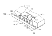
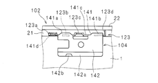
- FIG. 9 is an exploded perspective view of the main part on the back side showing a state in which the front cabinet 102 is attached to the panel module 1 by the L-shaped fixing member 104 according to the first modification
- FIG. 10 is an L-shaped fixing according to the first modification
- FIG. 11 is an exploded perspective view of a main part on the back side showing a state in which the member 104 is hooked on the flexible claw portion 123c.
- FIG. It is a disassembled rear view of the principal part of the back side which shows the state.
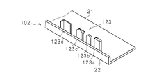
- 12 is a perspective view showing the main part of the front cabinet 102
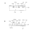
- FIG. 13 is a rear view and a side view showing the main part of the front cabinet 102
- FIG. 14 is a perspective view of the L-shaped fixing member 104
- FIG. FIG. 6 is a six-side view of an L-shaped fixing member 104.
- the latching means 123 includes a flexible claw 123c protruding from the rear surface of the frame plate portion 21 toward the back cabinet 3, and an L-shaped fixing with the flexible claw 123c latched. It has the 1st support member 123b which supports the member 104, the 2nd support member 123d, and the positioning protrusion 123a.
- the first and second support members 123b and 123d are provided on both sides of the flexible claw portion 123c along the panel module 1 facing the flexible claw portion 123c.
- the positioning projection 123a is arranged along the panel module 1 in which the flexible claw portion 123c is opposed to the positioning projection 123a, the first support member 123b, the flexible claw portion 123c, and the second support member 123d in this order. Is provided.
- the flexible claw portion 123c has a plate shape having a hook-like portion at the tip portion, and has a linear shape along the periphery of the frame plate portion 21 in a rear view as shown in FIG. 13A.
- the bowl-shaped part has an inclined surface on the inner side in the in-plane direction of the display surface 11a, and the outer side in the in-plane direction of the bowl-shaped part is flat.
- the first support member 123b has a substantially rectangular plate shape with a curved tip portion, and has a linear shape along the periphery of the frame plate portion 21 in the rear view as shown in FIG. 13A. As shown in FIGS. 9 and 10, the first support member 123b is configured to sandwich the L-shaped fixing member 104 hooked to the flexible claw portion 123c together with the flexible claw portion 123c. More specifically, the first support member 123b is located closer to the panel module 1 than the flexible claw 123c, and the L-shaped fixing member 104 moves from the flexible claw 123c to the panel module 1 side. Thus, it is prevented from falling off the hole 141c.
- the second support member 123d has an L shape that follows the side portion of the retaining plate 141 in a rear view, and a first plate piece that is substantially parallel to the surface of the opposing panel module 1 and a second member that is substantially vertical. It consists of a plate piece. As shown in FIGS. 9 and 10, the second support member 123 d holds the L-shaped fixing member 104 hooked on the flexible claw portion 123 c so as to be sandwiched with the flexible claw portion 123 c. More specifically, the 1st board piece which comprises the 2nd support member 123d is located in the panel module 1 side rather than the flexible nail
- a second plate piece constituting the second support member 123d is latched so as to sandwich the L-shaped fixing member 104 from both sides together with a positioning projection 123a described later.
- the positioning member is a member for abutting a protruding piece 141d protruding from the retaining plate 141 to position the mounting position of the L-shaped fixing member 104.
- a linear shape is formed along the periphery of the plate portion 21.
- the positioning member has a substantially rectangular plate shape as a whole.
- the L-shaped fixing member 104 moves in the direction along the peripheral edge of the panel module 1.
- a body 1232a that is, as shown to FIG. 13B, the 1st strip body 1231a and the 2nd strip body 1232a are formed in the board
- the L-shaped fixing member 104 has an L-shape as shown in FIGS. 14 and 15, a latch plate 141 having a hole 141 c for latching the flexible claw 123 c, and a rear surface of the panel module 1. It has the contact plate 142 which contacts.
- the latch plate 141 and the contact plate 142 are each substantially rectangular, and the long sides are continuous.
- FIG. 15 is a six-sided view of the L-shaped fixing member 104 provided on the upper part of the display device, with reference to the vertical and horizontal directions of the display device.
- 15A to 15F are a plan view, a front view, a left side view, a right side view, a rear view, and a bottom view of the L-shaped fixing member 104, respectively.
- the latching plate 141 has a hole 141c to which the flexible claw 123c is latched at a substantially central portion of the latching plate 141 along the longitudinal direction of the latching plate 141.
- the first and second recesses 141a to which the first and second support members 123b and 123d are to be supported are fitted to both sides of the hole 141c, that is, both sides in the longitudinal direction of the latch plate 141. 141b.
- the first and second recesses 141a and 141b are concave when viewed from the side where the contact plate 142 is provided, and convex when viewed from the side where the contact plate 142 is not provided (front side in FIG. 14). Is formed.
- the first and second recesses 141a and 141b have tip portions, that is, tongue portions that protrude toward the front cabinet 102 side.
- the tongue piece has a front end portion of the front cabinet 102 so that the first and second support members 123b and 123d can be easily inserted into the first and second recesses 141a and 141b of the L-shaped fixing member 104. It is bent to the part 22 side.
- a tongue piece projecting from the edge of the hole 141c toward the front cabinet 102 is provided.
- the tip of the tongue piece is also bent toward the panel module 1 so that the flexible claw 123c can be easily inserted and hooked into the hole 141c of the L-shaped fixing member 104.
- the latch plate 141 is formed with a projecting piece 141d projecting from the latch plate 141 toward the positioning projection 123a along the panel module 1 facing the latch plate 141.
- the contact plate 142 has a stepped portion 142 a on the long side portion that is not continuous with the retaining plate 141.
- the step portion 142a is bent so as to approach the frame plate portion 21 side, and a contact convex portion 142b that contacts the rear surface of the panel module 1 is formed on the step portion 142a.
- the contact protrusion 142b is protruded toward the panel module 1, and the contact protrusion 142b and the portion where the flexible claw 123c is hooked are separated in the direction along the peripheral edge of the panel module 1. ing.
- the contact protrusion 142b is separated from the portion where the flexible claw 123c is hooked toward the protruding piece 141d.
- FIG. 16 is a schematic diagram illustrating a method for attaching the L-shaped fixing member 104.
- the protruding piece 141d of the L-shaped fixing member 104 is brought into contact with the distal end portion of the positioning protrusion 123a to position the L-shaped fixing member 104.
- the L-shaped fixing member 104 is rotated around the positioning projection 123a while adjusting the posture of the L-shaped fixing member 104 so that the flexible claw portion 123c fits into the hole 141c.
- the L-shaped fixing member 104 is inserted into the latching means 123, and the flexible claw 123c is latched in the hole 141c.
- the L-shaped fixing member 104 can be easily attached and the assembly of fixing the front cabinet 102 to the panel module 1 is possible as compared with the display device according to the embodiment. Workability can be improved.
- the function and effect will be specifically described.
- the L-shaped fixing member 4 when the L-shaped fixing member 4 is attached to the latching means 23, the positioning operation of the L-shaped fixing member 4 and the flexible claw portion 23c on the L-shaped fixing member 4 due to its configuration. Therefore, the L-shaped fixing member 4 has a tendency to be difficult to attach compared to the display device according to the first modification. That is, when the support members 23a and 23b are inserted into the concave portions 41a and 41b of the L-shaped fixing member 4, the positional relationship between the hole 41c of the L-shaped fixing member 4 and the flexible claw portion 23c is fixed at this stage. End up.
- the L-shaped fixing member 104 is positioned such that the positional relationship between the flexible claw portion 123c and the hole portion 141c is not completely fixed, and then the L-shaped fixing member 104 is placed.
- the positioning operation of the L-shaped fixing member 104 is first performed by bringing the protruding piece 141d into contact with the positioning protrusion 123a, and then the positional relationship is such that the flexible claw portion 123c is fitted into the hole 141c.
- the L-shaped fixing member 104 is inserted into the latching means 123 by rotating the L-shaped fixing member 104 around the positioning projection 123a while adjusting the posture of the L-shaped fixing member 104 so that the flexible claw portion 123c can be hooked and the L-shaped fixing member 104 can be smoothly attached.
- the L-shaped fixing member 4 is attached when the hooking strength of the flexible claw portion 23c is increased for the purpose of strengthening the fixing between the front cabinet 2 and the panel module 1. At this time, the resistance force when the flexible claw portion 23c is hooked also increases, and the workability tends to be deteriorated as compared with the display device according to the first modification.
- the portion on which the flexible claw portion 123c is hooked and the abutting convex portion 142b are separated along the panel module 1, and thus can be described as will be described later.
- the force point of the flexible claw portion 123c and the action point of the contact convex portion 142b are separated from each other, and the resistance force when the L-shaped fixing member 104 is attached even if the engagement strength of the flexible claw portion 123c is increased. Does not change so much, and good workability can be maintained.
- FIG. 17 is a conceptual diagram showing the operation of the L-shaped fixing member 104 according to the first modification.
- FIG. 17A shows a force point a, a fulcrum point b, an action point c, and a force applied to the flexible claw portion 123c when the L-shaped fixing member 104 according to Modification 1 is hooked on the flexible claw portion 123c. It is the conceptual diagram which showed F.
- the L-shaped fixing member 104 When the L-shaped fixing member 104 is attached, the portion where the protruding piece 141d is in contact with the positioning projection 123a serves as a fulcrum b, and the L-shaped fixing member 104 is rotated so that the hole 141c is positioned more than the flexible claw 123c.
- the L-shaped fixing member 104 When moved to the 102 side (lower side in FIG. 17), the L-shaped fixing member 104 itself works like a leaf spring, and after the hooking plate 141 is bent, it returns to the point of force a of the hole 141c when returning to the original position.
- the flexible claw portion 123c is hooked. In this case, as shown in FIG.
- the portion where the protruding piece 141d is in contact with the positioning projection 123a is the fulcrum b, the portion where the flexible claw 123c is hooked is the force point a, and the panel module 1 is in contact.
- the contact convex portion 142b becomes the action point c.
- the value of k1 is relatively small, and even if the hook strength of the flexible claw 123c is increased or the hook strength varies due to manufacturing variations, A large force does not act on the flexible claw portion 123c. For this reason, the attachment workability of the L-shaped fixing member 104 does not deteriorate. Moreover, the front cabinet 102 does not dent by the great force acting on the flexible claw portion 123c, and the aesthetic appearance is not impaired.
- FIG. 17B shows the force point a of the force applied when the L-shaped fixing member 4 according to the embodiment is hooked on the flexible claw portion 23c, the action point c, and the force F applied to the flexible claw portion 23c.
- the force point a at which the flexible claw 23c is hooked and the action point c at which the L-shaped fixing member 4 is in contact with the panel module 1 are close to each other. Therefore, the value of k2 is relatively large, and when the engagement strength of the flexible claw portion 23c fluctuates, an unexpectedly large force is applied to the flexible claw portion 23c, and the mounting workability of the L-shaped fixing member 4 is deteriorated. Or the beauty of the front cabinet 2 may be impaired. As described above, in the display device according to the first modification, the attachment workability of the L-shaped fixing member 104 and the aesthetic appearance of the front cabinet 102 can be prevented from being impaired as compared with the embodiment.
- the flexible claw portion is for preventing the L-shaped fixing member from falling off, and after the L-shaped fixing member is attached to the front cabinet of the panel module, the flexible claw portion becomes the L-shaped fixing member. Little force is applied. For this reason, backlash occurs in the front-rear direction of the display device between the L-shaped fixing member and the panel module, and voice chatter or the like has occurred.
- a method such as attaching non-woven fabric Himeron to the contact portion between the L-shaped fixing member and the panel module can be considered.
- workability is reduced and the number of parts is increased.
- the display device according to the modified example 2 prevents voice chatter while avoiding a decrease in workability and an increase in the number of parts.
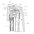
- FIG. 18 is an enlarged side cross-sectional view showing a main part of a display device according to Modification 2.
- the display device according to the modified example 2 includes the panel module 1, the front cabinet 202, and the back cabinet 203 as in the embodiment.
- the back cabinet 203 has the same configuration as that of the embodiment or the first modification, and includes a dish-shaped cover portion 231 that covers the back side of the panel module 1 and a rear cylinder portion 232 that continues to the periphery of the dish-shaped cover portion 231.
- the L-shaped fixing member 204 has an L-shape, and a latch plate 241 having a hole 241c on which the flexible claw 223c is latched, and the rear surface of the panel module 1.
- a contact plate 242 is in contact therewith.
- Each of the latching plate 241 and the contact plate 242 has a substantially rectangular shape, and the long sides are continuous with each other.
- the front cabinet 202 includes a frame plate portion 221 that covers the peripheral edge of the panel module 1 on the display surface side, and a front cylinder portion 222 that extends from the outer peripheral edge of the frame plate portion 221 to the rear and covers the outer periphery of the panel module 1.
- a latching means 223 for latching the L-shaped fixing member 204 is provided on the rear surface of the frame plate portion 221 and the inner surface of the front tube portion 222.
- a plurality of the latching means 223 are provided on both sides and the upper part of the front cabinet 202 in the lateral direction.
- the latching means 223 supports the flexible claw portion 223c that protrudes from the inner surface of the front cylinder portion 222 toward the panel module 1 and extends backward in the middle, and the L-shaped fixing member 204 on which the flexible claw portion 223c is latched. And a supporting member (not shown).
- the configuration of the support member is the same as that in the embodiment or the first modification.
- the base part 223e of the flexible claw part 223c has elasticity, and has a hinge function that rotates about the base part 223e toward and away from the panel module 1.
- a hook-shaped portion that is hooked on the L-shaped fixing member 204 is provided at the distal end portion of the flexible claw portion 223c.
- the length of the flexible claw portion 223c is set in accordance with the thinnest panel module 1 that varies depending on manufacturing errors. That is, when the front cabinet 202 is attached to the panel module 1 having the smallest width in the front-rear direction using the L-shaped fixing member 204, the L-shaped fixing member 204, the panel module 1, The dimension in the front-rear direction of the L-shaped fixing member 204 is determined so that the two come into close contact with each other.
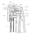
- FIG. 19 is an enlarged side sectional view showing the operation of the display device according to the second modification.
- the L-shaped fixing member 204 when the width in the front-rear direction of the panel module 1 is increased due to a manufacturing error, the L-shaped fixing member 204 is positioned closer to the right side (back side) than FIG. Since the L-shaped fixing member 204 has a hinge function, the L-shaped fixing member 204 rotates counterclockwise in FIG. In this case, even if there is a dimensional error of the panel module 1, the L-shaped fixing member 204 comes into contact with the back surface of the panel module 1 so that no chatter due to voice occurs. Further, even when the L-shaped fixing member 204 is positioned on the right side (back side) as compared with FIG. 18, the flexible claw portion 223 c changes the latching position with respect to the L-shaped fixing member 204, so The attachment of the member 204 does not require a large force.
- the L-shaped fixing member 204 is the panel module. 1 and can be prevented from being chattered by voice, and when attaching the L-shaped fixing member 204, it is not necessary to push the L-shaped fixing member 204 with a strong force, and the L-shaped fixing member 204 can be easily fixed. Member 204 can be attached.
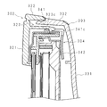
- FIG. 20 is an enlarged side cross-sectional view illustrating a main part of a display device according to the third modification.
- the display device according to the modification 3 includes the panel module 1, the front cabinet 302, and the back cabinet 303 as in the embodiment.
- the back cabinet 303 has the same configuration as that of the embodiment or the first modification, and includes a dish-shaped cover part 331 that covers the back side of the panel module 1 and a rear cylinder part 332 that continues to the periphery of the dish-shaped cover part 331. .
- the L-shaped fixing member 304 has an L-shape, and a latch plate 341 having a hole portion 341c to which the flexible claw portion 323c is latched, and the rear surface of the panel module 1.
- a contact plate 342 is provided.
- Each of the latching plate 341 and the contact plate 342 has a substantially rectangular shape, and the long sides are continuous with each other.
- the contact plate 342 is curved so that the back side is concave, and the contact plate 342 and the back surface of the panel module 1 are in line contact.
- the front cabinet 302 has a frame plate portion 321 that covers the peripheral edge of the panel module 1 on the display surface side, and a front tube portion 322 that continues from the outer peripheral edge of the frame plate portion 321 to the rear and covers the outer periphery of the panel module 1.
- a latching means 323 for latching the L-shaped fixing member 304 is provided on the rear surface of the frame plate portion 321 and the inner surface of the front tube portion 322.
- the configuration of the flexible claw portion 323c of the latching means 323 is the same as that of the embodiment.
- claw part 323c is set according to the thinnest panel module 1 which changes with manufacturing errors.
- the front cabinet 302 is attached to the panel module 1 having the smallest width in the front-rear direction using the L-shaped fixing member 304, the L-shaped fixing member 304, the panel module 1,
- the dimension in the front-rear direction of the L-shaped fixing member 304 is determined so that the two come into close contact with each other.
- FIG. 21 is an enlarged side sectional view showing the operation of the display device according to the third modification.
- the L-shaped fixing member 304 when the width in the front-rear direction of the panel module 1 is increased due to a manufacturing error, the L-shaped fixing member 304 is positioned closer to the right side (back side) than FIG. The L-shaped fixing member 304 rotates counterclockwise in FIG. 21 and is hooked on the L-shaped fixing member 304. In this case, even if there is a dimensional error of the panel module 1, the L-shaped fixing member 304 comes into contact with the back surface of the panel module 1 so as to be in line contact, and no chatter due to voice occurs.
- the L-shaped fixing member 304 changes the latching position with respect to the flexible claw portion 323c.
- the attachment of the member 304 does not require a large force.
- the L-shaped fixing member 304 is the panel module. It is possible to prevent chatter due to voice by making contact with 1 in close contact with each other, and when attaching the L-shaped fixing member 304, it is not necessary to push the L-shaped fixing member 304 with a strong force, and the L-shaped fixing member 304 can be easily fixed. Member 304 can be attached.
- FIG. 22 is an enlarged side cross-sectional view showing a main part of a display device according to Modification 4.
- the display device according to the modified example 4 includes the panel module 1, the front cabinet 402, and the back cabinet 403 as in the embodiment.
- the back cabinet 403 has the same configuration as that of the embodiment or the first modification, and includes a dish-shaped cover 431 that covers the back side of the panel module 1 and a rear cylinder 432 that is continuous with the periphery of the dish-shaped cover 431. .
- the front cabinet 402 includes a frame plate part 421 that covers the peripheral edge of the panel module 1 on the display surface side, and a front cylinder part 422 that extends rearward from the outer peripheral edge of the frame plate part 421 and covers the outer periphery of the panel module 1.
- a latching means 423 for latching the L-shaped fixing member 404 is provided on the rear surface of the frame plate portion 421 and the inner surface of the front tube portion 422.
- the configuration of the flexible claw portion 423c of the latching means 423 is the same as that of the embodiment or each modification. However, the dimension of the flexible claw portion 423c in the front-rear direction is configured such that the distal end portion of the flexible claw portion 423c is located on the back side with respect to the L-shaped fixing bracket fixed to the panel module 1. .
- the L-shaped fixing member 404 has an L-shape, and a latch plate 441 having a hole 441c on which the flexible claw 423c is latched, and the rear surface of the panel module 1.
- a contact plate 442 is in contact therewith.
- the front end of the flexible claw portion 423c protrudes to the back side from the panel module 1, and therefore, from the front cabinet 402 to the panel module during maintenance.
- the tip of the flexible claw portion 423 c can be seen well, and it is easy to put a finger on the tip of the flexible claw portion 423 c, and the panel module 1 can be easily removed.
Landscapes
- Physics & Mathematics (AREA)
- Nonlinear Science (AREA)
- Engineering & Computer Science (AREA)
- Optics & Photonics (AREA)
- Crystallography & Structural Chemistry (AREA)
- General Physics & Mathematics (AREA)
- Chemical & Material Sciences (AREA)
- Mathematical Physics (AREA)
- Multimedia (AREA)
- Signal Processing (AREA)
- Microelectronics & Electronic Packaging (AREA)
- Devices For Indicating Variable Information By Combining Individual Elements (AREA)
- Liquid Crystal (AREA)
- Casings For Electric Apparatus (AREA)
Abstract
Description
また、メンテナンスを行う際、可撓性爪部に引っ掛かっているL字固定部材を取り外すことによって、フロントキャビネットからパネルモジュールを容易に取り外すことができる。つまり、L字固定部材が取り外された可撓性爪部がパネルモジュールに引っ掛かることは無く、パネルモジュールを容易に取り外すことができる。
また、可撓性爪部の掛止位置は変化するため、パネルモジュールに製造誤差があっても、可撓性爪部を掛止させるためにL字固定部材を強く押し込むなどの必要は無くなる。
図1は、本発明の実施の形態に係る表示装置の一構成例を示す正面側の分解斜視図である。本実施の形態に係る表示装置は、例えば、液晶テレビなどのテレビ受像機である。表示装置は、前側に表示面11aを有し、略直方体をなすパネルモジュール1と、パネルモジュール1の周縁部を取り囲むフロントキャビネット2と、パネルモジュール1の後側を覆うバックキャビネット3と、パネルモジュール1にフロントキャビネット2を固定するための金属製のL字固定部材4と、映像信号を受信するチューナ5(受信部)と、電気回路6と、パネルモジュール1を起立状態で支持するスタンド7とを備える。
なお、可撓性爪部23c及び支持部材23a、23bの高さ、即ち表示装置の前後方向寸法は、前筒部22の前後方向寸法よりも短く構成すると良い。つまり、フロントキャビネット2を横方向から見た際、前筒部22に可撓性爪部23c及び支持部材23a、23bが隠れるように構成すると良い。このように構成することによって、表示装置の組み立て工程において、フロントキャビネット2から後側へ飛び出した可撓性爪部23c及び支持部材23a、23bが破損することを防止することができる。
従って、ビスを使用すること無くフロントキャビネット2にパネルモジュール1を固定することができ、しかもメンテナンスを行う際は、フロントキャビネット2からパネルモジュール1を容易に取り外すことができる。
図9は、変形例1に係るL字固定部材104によってパネルモジュール1にフロントキャビネット102を取り付けた状態を示す背面側の要部の分解斜視図、図10は、変形例1に係るL字固定部材104を可撓性爪部123cに掛止した状態を示す背面側の要部の分解斜視図、図11は、変形例1に係るL字固定部材104によってパネルモジュール1にフロントキャビネット102を取り付けた状態を示す背面側の要部の分解背面図である。図12は、フロントキャビネット102の要部を示す斜視図、図13は、フロントキャビネット102の要部を示す背面図及び側面図、図14は、L字固定部材104の斜視図、図15は、L字固定部材104の六面図である。
図16は、L字固定部材104の取り付け方法を示す模式図である。まず、L字固定部材104の突出片141dを位置決め突起123aの先端部に当接させ、L字固定部材104の位置決めを行う。そして、孔部141cに可撓性爪部123cが嵌り込むような位置関係になるようにL字固定部材104の姿勢を調整しながら、位置決め突起123aを中心にL字固定部材104を回転させることによってL字固定部材104を掛止手段123に挿入し、可撓性爪部123cを孔部141cに掛止させる。
しかし、変形例1に係る表示装置においては、可撓性爪部123cと孔部141cとの位置関係が完全に固定されないような形でL字固定部材104の位置決め行い、次いでL字固定部材104に可撓性爪部123cを掛止させる作業を順に行うことができるため、全体的にL字固定部材104の取り付け作業時間を短縮し、作業性を向上させることができる。具体的には、まず突出片141dを位置決め突起123aに当接させることによってL字固定部材104の位置決め作業を行い、次いで、孔部141cに可撓性爪部123cが嵌り込むような位置関係になるようにL字固定部材104の姿勢を調整しながら、位置決め突起123aを中心にL字固定部材104を回転させることによってL字固定部材104を掛止手段123に挿入し、可撓性爪部123cを掛止させることができ、円滑にL字固定部材104を取り付けることができる。
しかし、変形例1に係る表示装置においては、可撓性爪部123cが掛止する部分と、当接凸部142bとが、パネルモジュール1に沿って離隔しているため、後述するように可撓性爪部123cの力点と、当接凸部142bの作用点とが離れることになり、可撓性爪部123cの掛かり強さを大きくしてもL字固定部材104を取り付ける際の抵抗力はあまり変化せず、良好な作業性を維持することができる。
このように、変形例1に係る表示装置においては、実施の形態に比べて、L字固定部材104の取り付け作業性、フロントキャビネット102の美観が損なわれないようにすることができる。
変形例2に係る表示装置は、可撓性爪部の構成のみが実施の形態及び変形例1と異なるため、以下では主にこの相異点について説明する。可撓性爪部は、L字固定部材の脱落を防止するためのものであり、L字固定部材によってパネルモジュールのフロントキャビネットに取り付けられた後は、可撓性爪部はL字固定部材に殆ど力を加えない。このため、L字固定部材と、パネルモジュールとの間には、表示装置の前後方向においてガタが生じ、音声によるビビリ等が発生していた。ビビリの対策として、L字固定部材と、パネルモジュールとの接触部位に不織布ヒメロンを貼着するなどの方法が考えられるが、作業性の低下、部品点数の増加が問題となる。変形例2に係る表示装置は、作業性の低下、部品点数の増加を回避しつつ、音声によるビビリを防止するものである。
また、可撓性爪部223cの長さは、製造誤差によって変動する最も薄いパネルモジュール1に合わせて、設定されている。つまり、前後方向の幅が最も小さいパネルモジュール1に、L字固定部材204を用いてフロントキャビネット202を取り付けた場合、音声によりビビリが発生しない程度に、L字固定部材204と、パネルモジュール1とが密着して当接するように、L字固定部材204の前後方向の寸法が決定されている。
図20は、変形例3に係る表示装置の要部を示す拡大側断面図である。変形例3に係る表示装置は、実施の形態と同様、パネルモジュール1、フロントキャビネット302及びバックキャビネット303を備える。バックキャビネット303は、実施の形態又は変形例1と同様の構成であり、パネルモジュール1の背面側を覆う皿形覆部331と、皿形覆部331の周縁に連なる後筒部332とを有する。
図22は、変形例4に係る表示装置の要部を示す拡大側断面図である。変形例4に係る表示装置は、実施の形態と同様、パネルモジュール1、フロントキャビネット402及びバックキャビネット403を備える。バックキャビネット403は、実施の形態又は変形例1と同様の構成であり、パネルモジュール1の背面側を覆う皿形覆部431と、皿形覆部431の周縁に連なる後筒部432とを有する。フロントキャビネット402は、パネルモジュール1の表示面側の周縁を覆う枠板部421と、該枠板部421の外周縁から後方へ連なり、パネルモジュール1の外周を覆う前筒部422とを有する。枠板部421の後面及び前筒部422の内面には、L字固定部材404を掛止する掛止手段423が設けられている。掛止手段423の可撓性爪部423cの構成は、実施の形態又は各変形例と同様である。ただし、可撓性爪部423cの前後方向の寸法は、可撓性爪部423cの先端部が、パネルモジュール1に固定されたL字固定金具よりも背面側に位置するように構成されている。
2 フロントキャビネット
3 バックキャビネット
4 L字固定部材
5 チューナ
6 電気回路
7 スタンド
11 液晶パネル
11a 表示面
12 バックライト装置
13 保持枠体
21 枠板部
22 前筒部
23a、23b 支持部材
23c 可撓性爪部
24 当接部材
24a、24b 当接片(当接部材)
31 皿形覆部
32 後筒部
32a 規制爪部(規制部)
41 掛止板
41a,41b 凹部
41c 孔部
42 当接板
Claims (13)
- 前側に表示面を有するパネルモジュールと、該パネルモジュールの周縁部を取り囲むフロントキャビネットと、前記パネルモジュールの後側を覆うバックキャビネットとを備えた表示装置において、
前記フロントキャビネットの内面から前記バックキャビネット側へ突出した可撓性爪部と、
L字状をなし、該可撓性爪部が掛止する孔部を有する掛止板、及び前記パネルモジュールの後面に当接する当接板を含み、前記フロントキャビネットを前記パネルモジュールに固定するL字固定部材と
を備えることを特徴とする表示装置。 - 前記可撓性爪部が前記掛止板の孔部から外れる方向へ撓むことを規制する規制部を、前記バックキャビネットに備える
ことを特徴とする請求項1に記載の表示装置。 - 前記可撓性爪部が掛止した前記L字固定部材を支持する支持部材を前記フロントキャビネットに備える
ことを特徴とする請求項1又は請求項2に記載の表示装置。 - 前記支持部材は、
前記可撓性爪部が対向している前記パネルモジュールに沿って前記可撓性爪部の両側に2つ設けられ、前記可撓性爪部に掛止した前記掛止板を該可撓性爪部と共に挟み込むよう構成されており、
前記掛止板から該掛止板が対向している前記パネルモジュールに沿って突出した突出片と、
前記フロントキャビネットの内面から前記バックキャビネット側へ突出しており、前記突出片に当接して前記L字固定部材の取り付け位置を位置決めするための位置決め突起と
を備えることを特徴とする請求項3に記載の表示装置。 - 前記位置決め突起は、
前記L字固定部材を前記可撓性爪部に掛止させる場合に該L字固定部材が前記パネルモジュールの周縁部に沿った方向へ移動することを規制する第1条体と、
前記L字固定部材を前記可撓性爪部に掛止させる場合に該L字固定部材が前記バックキャビネット側へ移動することを規制する第2条体と
を備えることを特徴とする請求項4に記載の表示装置。 - 前記当接板は、
前記パネルモジュールの後面に当接する当接凸部を備え、
該当接凸部と、前記可撓性爪部が掛止する部分とは、前記パネルモジュールの周縁部に沿った方向に離隔している
ことを特徴とする請求項4又は請求項5に記載の表示装置。 - 前記フロントキャビネットの前記可撓性爪部よりも横方向及び上下方向内側に設けられており、前記パネルモジュールの外周面に当接する当接部材を備える
ことを特徴とする請求項1から請求項6までのいずれか一つに記載の表示装置。 - 前記可撓性爪部は、
前記フロントキャビネットの両側部及び上部の内面に設けられている
ことを特徴とする請求項1から請求項7までのいずれか一つに記載の表示装置。 - 前記フロントキャビネットは、
パネルモジュールの表示面側の周縁を覆う枠板部と、
該枠板部の外周縁から後方へ連なり、パネルモジュールの外周を覆う前筒部と
を有し、
前記可撓性爪部は、
前記前筒部の内面から突出しており、パネルモジュールに対して接離する方向へ撓むように構成してある
ことを特徴とする請求項1から請求項8までのいずれか一つに記載の表示装置。 - 前記当接板は、パネルモジュール側が凸になるように湾曲している
ことを特徴とする請求項1から請求項9までのいずれか一つに記載の表示装置。 - 前記可撓性爪部は、
先端が前記パネルモジュールよりも後側に位置している
ことを特徴とする請求項1から請求項10までのいずれか一つに記載の表示装置。 - 前記パネルモジュールは、
液晶パネルと、
該液晶パネルの後面側に配されたバックライト装置と、
前記液晶パネル及び前記バックライト装置を一体的に保持する保持枠体と
を備えることを特徴とする請求項1から請求項11までのいずれか一つに記載の表示装置。 - 請求項1から請求項12までのいずれか一つに記載の表示装置と、
映像信号を受信する受信部と
を備え、
前記表示装置は、
前記受信部が受信した映像信号にて映像を表示するようにしてある
ことを特徴とするテレビ受像機。
Priority Applications (4)
| Application Number | Priority Date | Filing Date | Title |
|---|---|---|---|
| US13/885,336 US8897018B2 (en) | 2010-11-29 | 2011-11-29 | Display device and television receiver |
| BR112013012612A BR112013012612A2 (pt) | 2010-11-29 | 2011-11-29 | dispositivo de exibição e receptor de televisão |
| CN201180053452.0A CN103221989B (zh) | 2010-11-29 | 2011-11-29 | 显示装置及电视接收机 |
| EP11845896.7A EP2648176B1 (en) | 2010-11-29 | 2011-11-29 | Display device and television receiver |
Applications Claiming Priority (6)
| Application Number | Priority Date | Filing Date | Title |
|---|---|---|---|
| JP2010265552 | 2010-11-29 | ||
| JP2010-265552 | 2010-11-29 | ||
| JP2011-145879 | 2011-06-30 | ||
| JP2011145879 | 2011-06-30 | ||
| JP2011-243646 | 2011-11-07 | ||
| JP2011243646A JP5100880B1 (ja) | 2010-11-29 | 2011-11-07 | 表示装置及びテレビ受像機 |
Publications (1)
| Publication Number | Publication Date |
|---|---|
| WO2012073943A1 true WO2012073943A1 (ja) | 2012-06-07 |
Family
ID=46171872
Family Applications (1)
| Application Number | Title | Priority Date | Filing Date |
|---|---|---|---|
| PCT/JP2011/077494 WO2012073943A1 (ja) | 2010-11-29 | 2011-11-29 | 表示装置及びテレビ受像機 |
Country Status (7)
| Country | Link |
|---|---|
| US (1) | US8897018B2 (ja) |
| EP (1) | EP2648176B1 (ja) |
| JP (1) | JP5100880B1 (ja) |
| CN (1) | CN103221989B (ja) |
| BR (1) | BR112013012612A2 (ja) |
| PL (1) | PL2648176T3 (ja) |
| WO (1) | WO2012073943A1 (ja) |
Cited By (4)
| Publication number | Priority date | Publication date | Assignee | Title |
|---|---|---|---|---|
| WO2013191230A1 (ja) * | 2012-06-22 | 2013-12-27 | シャープ株式会社 | 表示装置及びテレビジョン受信機 |
| WO2014132753A1 (ja) * | 2013-02-26 | 2014-09-04 | 京セラ株式会社 | 液晶表示装置 |
| US20150052920A1 (en) * | 2013-08-22 | 2015-02-26 | Samsung Electronics Co., Ltd. | Refrigerator with removable display |
| CN113031335A (zh) * | 2021-03-24 | 2021-06-25 | 武汉华星光电技术有限公司 | 显示装置 |
Families Citing this family (14)
| Publication number | Priority date | Publication date | Assignee | Title |
|---|---|---|---|---|
| JP6180184B2 (ja) * | 2013-05-22 | 2017-08-16 | 三菱電機株式会社 | フロント筐体固定構造 |
| TWI553597B (zh) * | 2013-09-24 | 2016-10-11 | 友達光電股份有限公司 | 具外力傳導結構之顯示裝置 |
| US9507377B2 (en) * | 2013-11-25 | 2016-11-29 | Kabushiki Kaisha Toshiba | Electronic device |
| JP2015125422A (ja) * | 2013-12-27 | 2015-07-06 | 船井電機株式会社 | 表示装置 |
| JP6289135B2 (ja) * | 2014-02-04 | 2018-03-07 | 三菱電機株式会社 | 筐体固定構造およびこれを備える表示装置 |
| CN104200752A (zh) * | 2014-08-14 | 2014-12-10 | 苏州佳世达电通有限公司 | 用以固定框架与显示模组的固定结构及显示装置 |
| KR102301424B1 (ko) * | 2015-05-19 | 2021-09-13 | 엘지전자 주식회사 | 디스플레이 장치 |
| CN106057075B (zh) * | 2016-05-17 | 2019-07-26 | 合肥惠科金扬科技有限公司 | 显示装置 |
| CN107526391B (zh) * | 2016-06-21 | 2020-05-08 | 鸿富锦精密电子(重庆)有限公司 | 显示器 |
| KR102390071B1 (ko) | 2017-09-25 | 2022-04-25 | 엘지전자 주식회사 | 디스플레이 디바이스 |
| JP2019109385A (ja) * | 2017-12-19 | 2019-07-04 | シャープ株式会社 | 表示装置 |
| JP2022030296A (ja) | 2020-08-06 | 2022-02-18 | 船井電機株式会社 | 電子機器および表示装置 |
| JP2023008539A (ja) * | 2021-07-06 | 2023-01-19 | オムロン株式会社 | 情報表示装置 |
| WO2023050357A1 (zh) * | 2021-09-30 | 2023-04-06 | 京东方科技集团股份有限公司 | 整机结构和显示装置 |
Citations (13)
| Publication number | Priority date | Publication date | Assignee | Title |
|---|---|---|---|---|
| JPH08314392A (ja) * | 1995-05-19 | 1996-11-29 | Fujitsu General Ltd | ディスプレイ装置 |
| JP2001100650A (ja) * | 1999-10-01 | 2001-04-13 | Hitachi Ltd | 情報表示装置 |
| JP2001305985A (ja) * | 2000-04-19 | 2001-11-02 | Nec Corp | 表示装置および情報端末機器 |
| WO2003009263A1 (fr) * | 2001-07-10 | 2003-01-30 | Fujitsu Limited | Structure plate |
| JP2003167235A (ja) * | 2001-12-03 | 2003-06-13 | Nec Kagoshima Ltd | 液晶表示装置の組み立て構造及びその組み立て方法 |
| JP2006221576A (ja) * | 2005-02-14 | 2006-08-24 | Toshiba Corp | 表示装置及び携帯情報処理装置 |
| JP2007279537A (ja) * | 2006-04-11 | 2007-10-25 | Sharp Corp | 薄型表示装置の表示パネル固定方法 |
| JP2007333911A (ja) * | 2006-06-14 | 2007-12-27 | Sharp Corp | 螺子締め表示、及び薄型表示装置 |
| JP2009042537A (ja) | 2007-08-09 | 2009-02-26 | Sharp Corp | 薄型表示装置 |
| JP2009200543A (ja) * | 2008-02-19 | 2009-09-03 | Panasonic Corp | キャビネット及び、ディスプレイ装置 |
| WO2010113797A1 (ja) * | 2009-03-31 | 2010-10-07 | 株式会社村元工作所 | 表示装置 |
| JP2010237548A (ja) * | 2009-03-31 | 2010-10-21 | Ips Alpha Technology Ltd | 液晶表示装置 |
| JP2010243719A (ja) * | 2009-04-03 | 2010-10-28 | Victor Co Of Japan Ltd | 筐体組み立て構造及び画像表示装置 |
Family Cites Families (12)
| Publication number | Priority date | Publication date | Assignee | Title |
|---|---|---|---|---|
| KR200285944Y1 (ko) * | 1999-05-26 | 2002-08-22 | 삼성전자 주식회사 | 엘씨디 모니터의 샤시 고정장치 |
| TW460854B (en) | 1999-07-13 | 2001-10-21 | Sanyo Electric Co | Flat display panel module and the display unit having the same |
| KR100381787B1 (ko) * | 2000-12-27 | 2003-04-26 | 삼성전자주식회사 | 디스플레이장치 |
| TWI222830B (en) * | 2003-03-26 | 2004-10-21 | Coretronic Corp | Image transmission system for rear projection television |
| KR100909135B1 (ko) | 2005-12-27 | 2009-07-23 | 파나소닉 주식회사 | 플라즈마 디스플레이 장치 |
| KR101385231B1 (ko) | 2006-08-24 | 2014-04-14 | 삼성디스플레이 주식회사 | 평판표시장치 |
| JP2009058915A (ja) * | 2007-09-04 | 2009-03-19 | Toshiba Corp | 液晶表示装置 |
| JP2009151112A (ja) * | 2007-12-20 | 2009-07-09 | Sharp Corp | 液晶表示装置及び液晶表示装置の組立方法 |
| KR20090074665A (ko) | 2008-01-02 | 2009-07-07 | 주식회사 대우일렉트로닉스 | 디스플레이 장치에서 프런트커버와 프레임간의 결합 구조 |
| CN201355855Y (zh) * | 2008-11-17 | 2009-12-02 | 康佳集团股份有限公司 | 一种平板电视前壳钩板固定结构 |
| US8264822B2 (en) * | 2009-03-30 | 2012-09-11 | JVC Kenwood Corporation | Image display apparatus and housing assembly configuration |
| JP2010252213A (ja) | 2009-04-20 | 2010-11-04 | Funai Electric Co Ltd | 薄型表示装置 |
-
2011
- 2011-11-07 JP JP2011243646A patent/JP5100880B1/ja active Active
- 2011-11-29 EP EP11845896.7A patent/EP2648176B1/en not_active Not-in-force
- 2011-11-29 US US13/885,336 patent/US8897018B2/en not_active Expired - Fee Related
- 2011-11-29 WO PCT/JP2011/077494 patent/WO2012073943A1/ja active Application Filing
- 2011-11-29 CN CN201180053452.0A patent/CN103221989B/zh not_active Expired - Fee Related
- 2011-11-29 PL PL11845896T patent/PL2648176T3/pl unknown
- 2011-11-29 BR BR112013012612A patent/BR112013012612A2/pt not_active IP Right Cessation
Patent Citations (13)
| Publication number | Priority date | Publication date | Assignee | Title |
|---|---|---|---|---|
| JPH08314392A (ja) * | 1995-05-19 | 1996-11-29 | Fujitsu General Ltd | ディスプレイ装置 |
| JP2001100650A (ja) * | 1999-10-01 | 2001-04-13 | Hitachi Ltd | 情報表示装置 |
| JP2001305985A (ja) * | 2000-04-19 | 2001-11-02 | Nec Corp | 表示装置および情報端末機器 |
| WO2003009263A1 (fr) * | 2001-07-10 | 2003-01-30 | Fujitsu Limited | Structure plate |
| JP2003167235A (ja) * | 2001-12-03 | 2003-06-13 | Nec Kagoshima Ltd | 液晶表示装置の組み立て構造及びその組み立て方法 |
| JP2006221576A (ja) * | 2005-02-14 | 2006-08-24 | Toshiba Corp | 表示装置及び携帯情報処理装置 |
| JP2007279537A (ja) * | 2006-04-11 | 2007-10-25 | Sharp Corp | 薄型表示装置の表示パネル固定方法 |
| JP2007333911A (ja) * | 2006-06-14 | 2007-12-27 | Sharp Corp | 螺子締め表示、及び薄型表示装置 |
| JP2009042537A (ja) | 2007-08-09 | 2009-02-26 | Sharp Corp | 薄型表示装置 |
| JP2009200543A (ja) * | 2008-02-19 | 2009-09-03 | Panasonic Corp | キャビネット及び、ディスプレイ装置 |
| WO2010113797A1 (ja) * | 2009-03-31 | 2010-10-07 | 株式会社村元工作所 | 表示装置 |
| JP2010237548A (ja) * | 2009-03-31 | 2010-10-21 | Ips Alpha Technology Ltd | 液晶表示装置 |
| JP2010243719A (ja) * | 2009-04-03 | 2010-10-28 | Victor Co Of Japan Ltd | 筐体組み立て構造及び画像表示装置 |
Non-Patent Citations (1)
| Title |
|---|
| See also references of EP2648176A4 |
Cited By (11)
| Publication number | Priority date | Publication date | Assignee | Title |
|---|---|---|---|---|
| WO2013191230A1 (ja) * | 2012-06-22 | 2013-12-27 | シャープ株式会社 | 表示装置及びテレビジョン受信機 |
| JP2014027646A (ja) * | 2012-06-22 | 2014-02-06 | Sharp Corp | 表示装置及びテレビジョン受信機 |
| CN104396233A (zh) * | 2012-06-22 | 2015-03-04 | 夏普株式会社 | 显示装置及电视接收器 |
| WO2014132753A1 (ja) * | 2013-02-26 | 2014-09-04 | 京セラ株式会社 | 液晶表示装置 |
| US9482898B2 (en) | 2013-02-26 | 2016-11-01 | Kyocera Corporation | Liquid crystal display apparatus |
| JP6034483B2 (ja) * | 2013-02-26 | 2016-11-30 | 京セラ株式会社 | 液晶表示装置 |
| US20150052920A1 (en) * | 2013-08-22 | 2015-02-26 | Samsung Electronics Co., Ltd. | Refrigerator with removable display |
| KR20150022127A (ko) * | 2013-08-22 | 2015-03-04 | 삼성전자주식회사 | 냉장고 |
| US10247470B2 (en) * | 2013-08-22 | 2019-04-02 | Samsung Electronics Co., Ltd. | Refrigerator with removable display |
| KR102220809B1 (ko) * | 2013-08-22 | 2021-02-26 | 삼성전자주식회사 | 냉장고 |
| CN113031335A (zh) * | 2021-03-24 | 2021-06-25 | 武汉华星光电技术有限公司 | 显示装置 |
Also Published As
| Publication number | Publication date |
|---|---|
| US8897018B2 (en) | 2014-11-25 |
| JP2013033190A (ja) | 2013-02-14 |
| PL2648176T3 (pl) | 2017-02-28 |
| JP5100880B1 (ja) | 2012-12-19 |
| EP2648176B1 (en) | 2016-10-05 |
| BR112013012612A2 (pt) | 2016-08-09 |
| CN103221989A (zh) | 2013-07-24 |
| US20130235277A1 (en) | 2013-09-12 |
| CN103221989B (zh) | 2015-09-30 |
| EP2648176A4 (en) | 2014-06-11 |
| EP2648176A1 (en) | 2013-10-09 |
Similar Documents
| Publication | Publication Date | Title |
|---|---|---|
| JP5100880B1 (ja) | 表示装置及びテレビ受像機 | |
| EP1777954B1 (en) | Liquid crystal television set, liquid crystal display | |
| US6128183A (en) | Attachment structure for a display device and an equipment in which such structure is provided | |
| KR20110054091A (ko) | 영상표시장치 | |
| JP4715220B2 (ja) | 液晶モジュ−ル | |
| JP4955063B2 (ja) | スピーカの取り付け構造およびフラットパネルディスプレイ | |
| JP2011227357A (ja) | 薄型表示装置 | |
| JP2009211933A (ja) | 表示装置 | |
| CN100516981C (zh) | 液晶显示器 | |
| US7999883B2 (en) | Display | |
| JP2009042537A (ja) | 薄型表示装置 | |
| US8011624B2 (en) | Stand attachment structure | |
| JP2008107751A (ja) | 表示パネルのホルダー及びホルダーにて表示パネルを取付けた表示装置 | |
| JP2013167827A (ja) | 表示装置及びテレビジョン受信機 | |
| JP5269354B2 (ja) | 表示装置 | |
| KR100741905B1 (ko) | 몰드프레임에 체결된 바텀 섀시의 이탈 방지 구조 | |
| JP2002207985A (ja) | カバー固定構造 | |
| JP6029564B2 (ja) | 表示装置 | |
| KR20080038886A (ko) | 패널형 디스플레이장치 | |
| JP2001067012A (ja) | 表示モジュール及びその取付構造 | |
| JP5478457B2 (ja) | 石油暖房機 | |
| JP4597836B2 (ja) | 表示装置の取付け構造 | |
| JP2009134048A (ja) | 表示装置 | |
| JP2024060121A (ja) | 表示装置 | |
| KR101232514B1 (ko) | 액정표시장치 |
Legal Events
| Date | Code | Title | Description |
|---|---|---|---|
| 121 | Ep: the epo has been informed by wipo that ep was designated in this application |
Ref document number: 11845896 Country of ref document: EP Kind code of ref document: A1 |
|
| DPE1 | Request for preliminary examination filed after expiration of 19th month from priority date (pct application filed from 20040101) | ||
| WWE | Wipo information: entry into national phase |
Ref document number: 13885336 Country of ref document: US |
|
| NENP | Non-entry into the national phase |
Ref country code: DE |
|
| REEP | Request for entry into the european phase |
Ref document number: 2011845896 Country of ref document: EP |
|
| WWE | Wipo information: entry into national phase |
Ref document number: 2011845896 Country of ref document: EP |
|
| ENP | Entry into the national phase |
Ref document number: 2013129750 Country of ref document: RU Kind code of ref document: A |
|
| REG | Reference to national code |
Ref country code: BR Ref legal event code: B01A Ref document number: 112013012612 Country of ref document: BR |
|
| ENP | Entry into the national phase |
Ref document number: 112013012612 Country of ref document: BR Kind code of ref document: A2 Effective date: 20130521 |