WO2012070643A1 - 錠剤分包装置 - Google Patents
錠剤分包装置 Download PDFInfo
- Publication number
- WO2012070643A1 WO2012070643A1 PCT/JP2011/077179 JP2011077179W WO2012070643A1 WO 2012070643 A1 WO2012070643 A1 WO 2012070643A1 JP 2011077179 W JP2011077179 W JP 2011077179W WO 2012070643 A1 WO2012070643 A1 WO 2012070643A1
- Authority
- WO
- WIPO (PCT)
- Prior art keywords
- carrier
- shutter
- tablet
- tray
- packaging
- Prior art date
- Legal status (The legal status is an assumption and is not a legal conclusion. Google has not performed a legal analysis and makes no representation as to the accuracy of the status listed.)
- Ceased
Links
- 0 CC1C*CC1 Chemical compound CC1C*CC1 0.000 description 1
Images














Classifications
-
- B—PERFORMING OPERATIONS; TRANSPORTING
- B65—CONVEYING; PACKING; STORING; HANDLING THIN OR FILAMENTARY MATERIAL
- B65B—MACHINES, APPARATUS OR DEVICES FOR, OR METHODS OF, PACKAGING ARTICLES OR MATERIALS; UNPACKING
- B65B5/00—Packaging individual articles in containers or receptacles, e.g. bags, sacks, boxes, cartons, cans, jars
- B65B5/10—Filling containers or receptacles progressively or in stages by introducing successive articles, or layers of articles
- B65B5/101—Filling containers or receptacles progressively or in stages by introducing successive articles, or layers of articles by gravity
- B65B5/103—Filling containers or receptacles progressively or in stages by introducing successive articles, or layers of articles by gravity for packaging pills or tablets
-
- A—HUMAN NECESSITIES
- A61—MEDICAL OR VETERINARY SCIENCE; HYGIENE
- A61J—CONTAINERS SPECIALLY ADAPTED FOR MEDICAL OR PHARMACEUTICAL PURPOSES; DEVICES OR METHODS SPECIALLY ADAPTED FOR BRINGING PHARMACEUTICAL PRODUCTS INTO PARTICULAR PHYSICAL OR ADMINISTERING FORMS; DEVICES FOR ADMINISTERING FOOD OR MEDICINES ORALLY; BABY COMFORTERS; DEVICES FOR RECEIVING SPITTLE
- A61J7/00—Devices for administering medicines orally, e.g. spoons; Pill counting devices; Arrangements for time indication or reminder for taking medicine
- A61J7/0069—Trays for holding or distributing medicines
-
- A—HUMAN NECESSITIES
- A61—MEDICAL OR VETERINARY SCIENCE; HYGIENE
- A61J—CONTAINERS SPECIALLY ADAPTED FOR MEDICAL OR PHARMACEUTICAL PURPOSES; DEVICES OR METHODS SPECIALLY ADAPTED FOR BRINGING PHARMACEUTICAL PRODUCTS INTO PARTICULAR PHYSICAL OR ADMINISTERING FORMS; DEVICES FOR ADMINISTERING FOOD OR MEDICINES ORALLY; BABY COMFORTERS; DEVICES FOR RECEIVING SPITTLE
- A61J7/00—Devices for administering medicines orally, e.g. spoons; Pill counting devices; Arrangements for time indication or reminder for taking medicine
- A61J7/0076—Medicament distribution means
-
- B—PERFORMING OPERATIONS; TRANSPORTING
- B65—CONVEYING; PACKING; STORING; HANDLING THIN OR FILAMENTARY MATERIAL
- B65B—MACHINES, APPARATUS OR DEVICES FOR, OR METHODS OF, PACKAGING ARTICLES OR MATERIALS; UNPACKING
- B65B35/00—Supplying, feeding, arranging or orientating articles to be packaged
- B65B35/30—Arranging and feeding articles in groups
- B65B35/32—Arranging and feeding articles in groups by gravity
-
- B—PERFORMING OPERATIONS; TRANSPORTING
- B65—CONVEYING; PACKING; STORING; HANDLING THIN OR FILAMENTARY MATERIAL
- B65B—MACHINES, APPARATUS OR DEVICES FOR, OR METHODS OF, PACKAGING ARTICLES OR MATERIALS; UNPACKING
- B65B57/00—Automatic control, checking, warning, or safety devices
- B65B57/10—Automatic control, checking, warning, or safety devices responsive to absence, presence, abnormal feed, or misplacement of articles or materials to be packaged
-
- B—PERFORMING OPERATIONS; TRANSPORTING
- B65—CONVEYING; PACKING; STORING; HANDLING THIN OR FILAMENTARY MATERIAL
- B65B—MACHINES, APPARATUS OR DEVICES FOR, OR METHODS OF, PACKAGING ARTICLES OR MATERIALS; UNPACKING
- B65B65/00—Details peculiar to packaging machines and not otherwise provided for; Arrangements of such details
- B65B65/08—Devices for counting or registering the number of articles handled, or the number of packages produced by the machine
-
- A—HUMAN NECESSITIES
- A61—MEDICAL OR VETERINARY SCIENCE; HYGIENE
- A61J—CONTAINERS SPECIALLY ADAPTED FOR MEDICAL OR PHARMACEUTICAL PURPOSES; DEVICES OR METHODS SPECIALLY ADAPTED FOR BRINGING PHARMACEUTICAL PRODUCTS INTO PARTICULAR PHYSICAL OR ADMINISTERING FORMS; DEVICES FOR ADMINISTERING FOOD OR MEDICINES ORALLY; BABY COMFORTERS; DEVICES FOR RECEIVING SPITTLE
- A61J1/00—Containers specially adapted for medical or pharmaceutical purposes
- A61J1/03—Containers specially adapted for medical or pharmaceutical purposes for pills or tablets
-
- A—HUMAN NECESSITIES
- A61—MEDICAL OR VETERINARY SCIENCE; HYGIENE
- A61J—CONTAINERS SPECIALLY ADAPTED FOR MEDICAL OR PHARMACEUTICAL PURPOSES; DEVICES OR METHODS SPECIALLY ADAPTED FOR BRINGING PHARMACEUTICAL PRODUCTS INTO PARTICULAR PHYSICAL OR ADMINISTERING FORMS; DEVICES FOR ADMINISTERING FOOD OR MEDICINES ORALLY; BABY COMFORTERS; DEVICES FOR RECEIVING SPITTLE
- A61J7/00—Devices for administering medicines orally, e.g. spoons; Pill counting devices; Arrangements for time indication or reminder for taking medicine
- A61J7/04—Arrangements for time indication or reminder for taking medicine, e.g. programmed dispensers
Definitions
- This invention relates to a tablet packaging device for packaging tablets for each prescribed dose into blister pack type trays (hereinafter simply referred to as “tray”).
- Patent Document 1 a tablet packaging device that automatically distributes and packs tablets prescribed in a tray having storage recesses partitioned into 7 rows and 4 columns.
- the tray is configured such that tablets packed in accordance with the number of doses four times a day are stored in each storage recess for one row, and one week can be stored in all seven rows.
- a scraper unit is provided on a belt conveyor that conveys a tray so as to be movable back and forth in the transverse direction of the conveyor.
- the trays are installed and transported with the rows of the storage recesses in the direction of the width of the conveyor and the columns in the direction of the conveyor.
- the scraper unit is provided with four sections corresponding to the storage recesses in four positions per row of the tray, and a scraper (scraping tool) is provided in each section.
- the above scraper unit sequentially moves under the tablet discharge hopper for each of the four sections, accepts the tablets, and each section is divided into four sections in one row of the tray with the tablets distributed to all four sections. Advancing onto the conveyor to match the upper opening of each storage recess. The shutters of each section of the scraper unit are opened in a state where they are aligned vertically, and at the same time, the internal tablet is scraped out by the operation of the scraper, and is individually discharged into the four storage recesses of the tray.
- the above-mentioned scraper unit repeats a cycle of receiving tablets into four sections, opening and closing the shutter, and scraping out the tablets by the scraper in order seven times.
- the belt conveyor repeats advance and stop seven times for each line of the tray, thereby completing the discharge and reception into the storage recess.
- the tray is carried out by the belt conveyor, taken out from the discharge portion to be packaged.
- the operation process of the scraper unit per tray repeats the cycle of accepting tablets into each of the four locations, opening the shutter, and scraping with the scraper seven times. There is a problem that the packaging efficiency is low.
- the belt conveyor repeatedly advances and stops in small increments, so there is a possibility that the tablets will deviate from the storage recess due to vibration and may be chipped. Yes, the higher the transport speed, the higher the possibility. Further, when the bottom of the storage recess is shallow, or when the shape of the storage recess is a concave spherical surface, the possibility of popping out is higher, which causes a packaging error.
- the present invention receives all the tablets for one tray by one carrier, moves the carrier to the tray waiting at the discharge position, and discharges the tablets all at once in the storage recesses of the tray.
- Another object of the present invention is to provide a tablet packaging device having high packaging efficiency, few packaging mistakes, and a simplified structure.
- a necessary gap is required between the tray and the carrier moving in the plane above the tray so as not to prevent free movement of the carrier.
- the tablet may deviate from the gap to the outside.
- another object of the present invention is to eliminate the gap when discharging the tablets from the carrier to the tray so that the tablets can be reliably transferred to the tray side.
- another problem is to eliminate the possibility of damage to the tray and the carrier due to an impact when the tray is pressed against the bottom surface of the carrier.
- the carrier is provided with a number of compartments that match the storage recesses of the tray, and when the tablets are transferred to the tray, a structure is employed in which the open bottom surface of the compartments is simultaneously opened and closed with a single shutter.
- dust such as chipping of tablets may adhere to the shutter, and there is a concern that the dust is discharged to the tray side together with the tablets.
- Another object of the present invention is to remove dust adhering to the shutter of the carrier in advance so that the dust is not discharged into the storage recess of the tray.
- tablets are received in all compartments of the carrier and automatically checked to see if the tablets are securely stored in each compartment before being transferred to the tray.
- the carrier is moved to the collection position and transferred to the collection tray.
- the tablet may bounce off the bottom of the collection tray and deviate from the collection tray, or the tablet may be chipped. Therefore, another object of the present invention is to prevent the tablets from rebounding in the collection tray.
- a packaging unit is provided at a lower part of a dispensing port of a tablet to be dispensed according to a prescription, and a required number of storages partitioned into a plurality of rows and columns in the packaging unit.
- the packaging unit includes the tray mounting table and the mounting table.
- a moving device a carrier having an upper and lower open compartment that can match the position of the storage recess of the tray, a driving device for the carrier, a shutter provided on the bottom surface of the carrier for opening and closing the compartment, and the shutter
- the moving device of the mounting table includes an opening / closing device, and moves the mounting table between a tray handling position and a standby position in synchronization with the movement of the carrier.
- the driving device executes a transporting process in which the carrier is returned to the original position in order through the receiving position set in the lower part of the dispensing port and the receiving end position in order, with the discharge position set in the upper part of the standby position as the original position.
- the receiving chamber receives the tablets by sequentially moving the compartments of the carrier below the dispensing port during the period from the reception start position to the reception end position.
- the shutter is opened when the receiving end position is returned to the discharge position, and the rest are closed (claim 1).
- the carrier While the carrier carries out one cycle of the transporting process, it receives tablets for one tray into all the compartments, transports them onto the trays, and opens the shutter to release the tray recesses corresponding to the compartments. Are discharged all at once.
- the tray only moves between the tray handling position and the standby position by a moving device different from the carrier driving device. However, there is a need for a timing relationship that the stage has been moved to the standby position before the carrier returns to the discharge position.
- the moving device of the mounting table is configured by a drawer provided so as to be freely inserted into and retracted from the packaging unit, and when the mounting table is installed inside the drawer and the drawer is pulled out It is possible to adopt a configuration in which the mounting table is in a tray handling position outside the packaging unit and is set in a standby position inside the packaging unit when pushed in (claim 2).
- the mounting table is supported by a vertical movement device, and the vertical movement device is operated when receiving a tablet from the carrier at the standby position, whereby the tray on the mounting table approaches or contacts the bottom of the carrier.
- the structure to make can be taken (Claim 3).
- the carrier driving device may be configured by an XY driving mechanism that moves the carrier in an X direction in a horizontal plane and in a Y direction perpendicular thereto (Claim 5).
- the XY drive mechanism is supported between a Y-direction drive motor, an X-direction drive motor, Y-direction drive belts installed at two left and right sides of the packaging portion, and the two Y-direction drive belts.
- the X direction drive motor and the X direction drive belt are mounted on the casing, the Y direction drive belt is provided by the Y direction drive motor, and the X direction drive motor is provided in the X direction.
- Each of the carriers is driven by a drive motor, and the carrier is connected to an X-direction slider attached to the X-direction drive belt via a bracket provided on the carrier.
- the bracket may be detachably engaged with the carrier, and the carrier may be detachably connected to the bracket by a lock member.
- the carrier When there is a tablet delivery error in each compartment of the carrier that has returned from the receiving position to the discharge position, the carrier is moved to the collection position before the shutter is opened, and the shutter is opened at the collection position to release the internal tablet. It is possible to adopt a configuration that discharges all to the collection tray. It is desirable to lay a cushion sheet on the inner bottom surface of the collection tray.
- a shutter guide member is provided on the bottom surface of the carrier, and a hole is provided in the shutter guide member so as to match a compartment of the carrier, and the shutter is disposed in the front-rear direction between the shutter guide member and the carrier bottom surface. It is possible to adopt a configuration in which an engagement side is provided at a rear end portion of the shutter.
- the shutter opening / closing device includes an opening mechanism and a closing mechanism, and the opening mechanism includes a shutter opening / closing motor, shutter opening belts installed in the front and rear directions at two left and right positions of the packaging portion, and the opening belt.
- the contractible spring is constituted by a winding type spring that exerts a spring force in the winding direction, the spring case is fixed to the shutter guide member, and the free end of the spring in the contracted state is in a closed state. It is connected to a part of a shutter, and when the shutter is opened by the opening mechanism, the spring is pulled out, and when the engagement bar returns to the original position, the retracted state is retracted to close the shutter. be able to.
- a brush is provided at the rear end of the carrier so as to contact the upper surface of the shutter, and a dust discharge slit is provided along the brush on the shutter guide member, and the front end side of the shutter has a range close to its full width.
- a shutter slit having a length close to the full width is provided in each of the cutout portion and the portion along the rear edge, and when the shutter is fully opened, the cutout portion is aligned with the dust discharge slit, and the shutter is fully closed.
- the positional relationship between the dust discharge slit, the notch and the shutter slit can be set so that the shutter slit matches the dust discharge slit.
- the tablet packaging apparatus can store a predetermined tablet in all the storage recesses in one cycle of the carrier transport process, and thus has an effect of high packaging efficiency.
- the tray is stationary at the standby position, and after the tablets are stored, the tray is moved to the tray handling position by the moving device of the mounting table. Since the movement only needs to be completed during the process of one cycle of the carrier, it may be relatively slow. For this reason, there is little vibration which the tablet stored in the storage recessed part of a tray receives, and troubles, such as deviating to the exterior of a tray in the middle of conveyance, are eliminated.
- the upper surface of the shutter can be cleaned when the shutter is opened and closed, and dust such as tablet chips can be prevented from being discharged into the tray.
- the carrier By operating the lock member, the carrier can be removed from the apparatus, and the carrier can be taken out and subjected to leaning or the like.
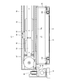
- FIG. 1 is a front view of a tablet packaging device according to an embodiment.
- FIG. 2 is a side view of FIG.
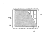
- FIG. 3A is a partially cutaway plan view of the tray with a lid attached.
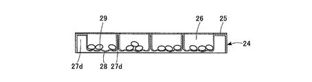
- 3B is a cross-sectional view taken along line X1-X1 of FIG. 3A.
- 4A is a partially enlarged cross-sectional view of FIG. 3A.
- FIG. 4B is a partially enlarged cross-sectional view at the time of use of FIG. 3A.
- 4C is a partially enlarged cross-sectional view in another state during use of FIG. 3A.
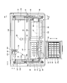
- FIG. 5 is a cross-sectional view taken along line X2-X2 with the cover of FIG. 2 removed.
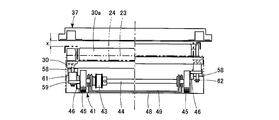
- FIG. 6A is an explanatory diagram viewed from the front of the drawer showing the positional relationship between the mounting table in the standby position and the carrier.
- FIG. 6B is an explanatory view seen from the side of the drawer showing the positional relationship between the mounting table and the carrier in the standby position.
- 6C is a partial side view of FIG. 6B.
- FIG. 7 is a plan view showing a portion of the vertical movement device.
- FIG. 8A is a schematic diagram showing the movement positions of the mounting table and the carrier.
- FIG. 8B is a plan view of the carrier.
- FIG. 9A is a perspective view of the carrier.
- FIG. 9B is a partially cutaway perspective view when the shutter is fully opened.
- FIG. 9C is a partially cutaway perspective view with the carrier omitted.
- FIG. 10A is a cross-sectional plan view of the carrier portion.
- FIG. 10B is an enlarged side view showing a part of FIG. 10A.
- 10C is a cross-sectional view taken along line X3-X3 of FIG. 10B.
- FIG. 11A is a cross-sectional view of the dust discharge portion of the carrier.
- FIG. 11B is a cross-sectional view of the carrier when dust is discharged.
- FIG. 11C is a cross-sectional view in another state when the carrier is discharged.
- FIG. 12A is a cross-sectional view of the carrier portion.
- FIG. 12B is an enlarged cross-sectional view of a coupling portion between the carrier and the shutter guide member.
- FIG. 12C is an enlarged cross-sectional view taken along line X4-X4 of FIG. 12A.
- FIG. 13 is an enlarged cross-sectional view of the X5-X5 line in FIG.
- FIG. 14 is a partially omitted enlarged cross-sectional view taken along line X6-X6 of FIG.
- FIG. 15 is a partially omitted sectional view taken along line X7-X7 of FIG.
- FIG. 16A is a partially cutaway plan view of the collection tray.
- FIG. 16B is an enlarged cross-sectional view taken along line X8-X8 of FIG. 16A.
- FIG. 17 is a front view showing an example of a display screen for prescription input when hand-rolling.
- FIG. 17 is a front view showing an example of a display screen for prescription input when hand-rolling.
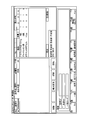
- FIG. 18 is a front view showing an example of a discharge monitor display screen when hand-rolling.
- FIG. 19 is a front view showing 1 of the manual tablet auxiliary screen.
- FIG. 20 is a front view showing the hand-drawn tablet auxiliary screen 2.
- FIG. 21 is a front view showing 3 of the manual tablet auxiliary screen.
- FIG. 22 is a front view showing a hand-made tablet auxiliary screen 4.
- the tablet packaging device 11 shown in FIG. 1 is provided with a tablet storage unit 13 in the upper half of the frame 12, and a packaging unit 14 (see FIG. 2) protruding forward from the upper half in the lower half.
- a storage unit 15 such as an empty tray is provided in the lower part.
- a large number of tablet cassettes 16 are stored in the tablet storage unit 13 in a multi-stage shape, and a tablet feeder 17 is installed below each tablet cassette 16.
- the tablet storage unit 13 is opened and closed in the up and down direction by a shingled shutter 18.
- a tablet dispensing chute 19 is provided below the tablet feeder 17, and a receiving port 20 (see FIG. 5) facing the lower end of the dispensing chute 19, and a downward dispensing port 21 communicating with the receiving port 20 is the above-described packaging portion. 14 is provided at the top.
- a prescription tablet is dispensed from the dispensing port 21 every time, for example, four times a day for one week or three times a day for 5 days. .
- the tablets dispensed from the dispensing port 21 are finally stored in the tray 24 shown in FIGS. 3A to 4C. Therefore, the tray 24 will be described next.
- FIG. 3A and 3B show a state in which the lid sheet 25 is attached to the open surface of the tray 24.
- the tray 24 has storage recesses 26 that are partitioned into 7 rows by 4 columns.
- the side walls 27a facing each other on the long side of the tray 24, the side walls 27b facing each other on the short side, and the partition walls 27c partitioning them in 7 rows and 4 columns are formed at the same height and intersect in a lattice shape. As a result, a uniform rectangular storage recess 26 is formed.
- the thick portions on the bottom side of the side walls 27a, 27b and the partition wall 27c are stolen by the grooves 27d and formed with a thickness that maintains a certain strength.
- the thickness of the bottom surface of the storage recess 26 is made thinner than this, and is formed so as to have many irregularly shaped ridges 28. Since the bottom surface is thin and has many ridges 28, the buffering action of the tablet 29 accommodated therein can be exhibited, and when it is pushed up from the bottom surface, it is deformed into a mountain shape (see the two-dot chain line in FIG. 4C).
- the internal tablet 29 can be easily taken out.
- the lid sheet 25 is a paper sheet having a size that coincides with the entire open side of the tray 24, and has an adhesive at the long side wall 27a, the short side wall 27b, and the partition wall 27c. 31 (see FIG. 4A).
- the lid sheet 25 is formed with a break removal portion 31b surrounded by a break line 31a due to a square half cut, perforation or the like that matches the size of the storage recess 26 (see FIG. 4A).
- the 7th day display 32 and the date display 33 corresponding to the 7th day display are provided on each of the margins for 7 lines in the vertical direction of the break removal part 31b.
- a display 34 such as “Asa” to “Before Neru” and other indications are given.
- prescription display 35 such as a prescription person's name, the time of taking, a tablet name, and its quantity, is given to the fracture removal part 31b. In the case of the illustration, it is displayed that the tablets for one week are accommodated four times a day, but depending on the prescription, different amounts may be accommodated, such as three times a day for five days.
- the prescriber pushes the corresponding rupture removal part 31b with his fingertip and breaks at the rupture line 31a every four times of the corresponding day (see FIG. 4B). Since the breakage removing portion 31b is pushed into the storage recess 26, it is picked up with the fingertip or the bottom surface is pushed up with the fingertip and taken out together with the tablet 29 (see FIG. 4C).
- the break removing portion 31b is broken and removed, and the storage recess 26 is opened. Therefore, it is possible to easily check whether or not the user has forgotten to take a dose simply by distinguishing whether the storage recess 26 is open or not.
- FIG. 5 shows a cross-sectional plan view with the cover lid 22 removed and the upper half of the frame 12 cut and removed.
- the packaging part 14 is provided with a drawer 23 that can be pulled forward and pushed into the packaging part 14, and a mounting table 30 for the tray 24 is installed inside the drawer 23.
- the drawer 23 constitutes a “mounting table moving device” referred to in the claims. In the illustrated case, the drawer 23 is manually pulled out and pushed in (see double-headed arrows in FIGS. 2 and 5), but may be automatically driven.
- the component of the packaging unit 14 receives the drawer 23, the mounting table 30 installed in the drawer 23, and the tablet 29 discharged from the dispensing port 21.
- a carrier 37 that conveys to the upper portion of the tray 24 on the top 30; a shutter 38 that opens and closes the bottom surface of the carrier 37 (see FIG. 9B); a drive device 39 that moves the carrier 37 to a predetermined position in the plane;
- the apparatus 40 is a main component.
- a vertical movement device 41 (see FIGS. 6A and 7) is provided, and the mounting table 30 is installed on the vertical movement device 41.
- the vertical movement device 41 includes a vertical movement motor 42 (see FIG. 7), two rotary shafts 44 arranged along the front end and the rear end of the drawer 23 and interlocked with each other by a belt 43, and both end portions of each rotary shaft 44.
- the cam follower 46 (see FIG. 6A) provided at the eccentric position of the outer surface of each eccentric cam wheel 45.
- the cam followers 46 are provided at the same phase position in the rotational direction for all the eccentric cam wheels 45, and all the cam followers 46 maintain the same phase, that is, maintain the same height by the rotation of the motor 42. Rotate to.
- a bearing 47 (see FIG. 7) that supports the rotating shaft 44 disposed on the rear end side of the drawer 23 is attached to the fixed bracket plate 48, and the bearing 47 of the rotating shaft 44 disposed on the front end side is a movable bracket. Attached to the plate 49. Both bracket plates 48 and 49 overlap each other in a plane, and a fixing screw 52 is inserted into a long hole 51 provided in the overlap portion in the front-rear direction.
- the adjustment plates 53 and 54 provided on the bracket plates 48 and 49 are opposed to each other, and the feet of the adjustment bolts 55 and 56 screwed into the adjustment plates 53 and 54 from the opposite sides are connected to the other adjustment plate 53, 54.
- the distance between the front and rear rotating shafts 44 is adjusted by moving the movable bracket plate 49 forward and backward.
- guide pins 58 fixed downward are provided, and the sleeve 61 is fitted to the guide pins 58 so that the sleeve 61 can slide with a certain stroke in the vertical direction.
- a contact plate 59 is integrally provided at the lower end of the sleeve 61.
- a retaining member 62 is provided at the lower end of the guide pin 58 to prevent the sleeve 61 from coming off downward.
- the placing table 30 is placed on the placing table support members 57 provided at the two left and right positions on the bottom surface of the drawer 23. Appear. At this time, there is a gap between the sleeve 61 and the mounting table 30, and as a result, a gap x also exists between the tray 24 and the bottom surface of the carrier 37 (see the left half of FIG. 6A). Due to the presence of the gap x, the carrier 37 can freely move in a plane at the height without contacting the tray 24.
- the coil spring 60 constituting the damper is accommodated in the sleeve 61 (see FIG. 6C), and the free end at the upper end of the coil spring 60 is brought into contact with the bottom surface of the mounting table 30. Thereby, the impact when the tray 24 contacts the carrier 37 is reduced.
- a plurality of trays 24 are placed on the mounting table 30 within a range that can be accommodated in the gap x, and the next step is performed simply by removing the trays 24 in which the tablets 29 have been stored in order from the top.
- the case where it handles is considered. Even in this case, the entire plurality of trays 24 can be pressed against the bottom surface of the carrier 37 by the compression elasticity of the coil spring 60.
- tray support ribs 30 a are formed on the upper surface of the mounting table 30 so as to correspond to the tray 24, and are divided into 7 sections in the left-right direction and 4 sections in the front-rear direction.
- the tray 24 is placed on the tray support rib 30a in such a posture that its seven sections are directed in the left-right direction.
- the side walls 27a and 27b of the tray 24 and the groove 27d on the back surface of the partition wall 27c are fitted to the support rib 30a, so that the tray 24 is stably supported.
- a dust receiving tray 64 that is long in the left-right direction is detachably attached to the drawer 23 at the rear end of the tray support rib 30a (see FIGS. 5 and 7). A configuration for collecting the dust attached to the shutter 38 by the dust receiving tray 64 will be described later.
- a tray handling position a The position of the mounting table 30 in the state of FIG. 5 where the mounting table 30 is pulled out of the packaging unit 14 by pulling out the drawer 23 is referred to as a tray handling position a (see FIG. 8A).
- the operator places an empty tray 24 on the mounting table 30 and removes the tray 24 in which tablets are stored from the mounting table 30.
- the tray 24 on the mounting table 30 is rotated 90 ° clockwise from the mode shown in FIG. 3A, and seven rows from “month” to “day” are arranged in the left-right direction (X direction), and the front-rear direction (Y direction). Are placed on the mounting table 30 in such a manner that four rows from “Asa” to “Before Neru” are arranged.
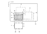
- FIG. 8A schematically shows the movement of the drawer 23 inside the packaging part 14, the mounting table 30 provided on the drawer 23, and the carrier 37, and the horizontal direction toward the packaging part 14. Is shown as the X direction and the front-rear direction as the Y direction.
- the position of the mounting table 30 when the drawer 23 is pushed into the packaging part 14 is referred to as a standby position b.
- the amount of movement of the drawer 23 in the front-rear direction (Y direction) is such that when the drawer 23 is pulled out, the placing table 30 is in the tray handling position a outside the packaging unit 14 and when it is pushed in, the waiting inside the packaging unit 14 It is set to be at position b.
- the carrier 37 is divided into seven sections in the X direction (left-right direction) and four sections in the Y direction (front-rear direction) by providing a grid-shaped partition wall 66 inside the rectangular frame 65.
- a partitioned compartment 67 is formed.
- Each compartment 67 is opened up and down, and the size thereof corresponds to each storage recess 26 of the tray 24.
- FIG. 8B an x number of 1 to 7 in the X direction of the compartment 67 and a y number of 1 to 4 in the Y direction are virtually attached, and the position of each compartment 67 is coordinated. Called by display (x, y).
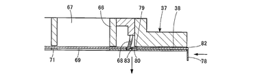
- a brush 68 having a length full of the inner side surface of the rear side is attached downward between the inner side surface of the rear side of the frame 65 and the compartment 67 (see FIG. 9B). As will be described later, the brush 68 is used for cleaning the upper surface of the shutter 38.
- a thin plate-like shutter guide member 71 is fixed to the bottom surface of the carrier 37 with a certain gap in the vertical direction.
- the shutter guide member 71 is formed with a square hole 69 having an arrangement and a size corresponding to the bottom surface of the compartment 67 (see FIG. 9C).
- a dust discharge slit 80 is formed at a position corresponding to the brush 68 provided in the carrier 37 so as to reach near both sides in the left-right direction (see FIG. 9C).
- the shutter guide member 71 is provided with connecting sides 74 bent upward on the left and right sides, and the connecting sides 74 are arranged along both sides of the carrier 37 (see FIGS. 9A to 9C).
- the connecting side 74 is fixed to the carrier 37 (see FIGS. 12A and 12B) with a fixing screw 75, whereby the carrier 37 and the shutter guide member 71 are integrated.
- the shutter 38 is formed of a single stainless plate that is substantially equal to the width in the left-right direction of the frame 65 of the carrier 37 and the length in the front-rear direction.
- a guide side 77 bent upward is formed on both the left and right sides, and an engagement side 78 bent downward is formed on the rear end.
- a parallel dust discharge slit 79 is provided so as to reach the vicinity of the left and right guide sides 77.
- the front end side is provided with a shallow notch 81 (see FIG. 9C) having the same length as the slit 79.
- the shutter 38 is inserted in a gap between the carrier 37 and the shutter guide member 71 so as to be slidable in the front-rear direction from an insertion port 82 (see FIGS. 11A to 11C) on the rear end side of the carrier 37.
- the bottom surface and the left and right side edges are guided by the member 71.
- the left and right guide sides 77 are guided by the guide roller 72 of the shutter guide member 71 (see FIG. 12A).
- the shutter 38 When the shutter 38 is inserted most deeply, it overlaps the entire bottom surface of the carrier 37 and closes the bottom surfaces of all the compartments 67 (see FIG. 11A). At this time, the shutter 38 does not adhere to the bottom surface of the carrier 37 and prevents passage of the tablet 29, but there is a gap ⁇ having a size that allows passage of the dust 83 such as chipping of the tablet 29 that is small below a certain level. Is set as follows.
- the dust discharge slit 79 coincides with the upper surface of the slit 80 of the shutter guide member 71.
- the carrier 37 is connected to a driving device 39 via a gate-shaped bracket 70 (see FIG. 9A), and is driven by the driving device 39 integrally with the shutter 38 and the shutter guide member 71. Control is performed so that one cycle of the transfer process is performed per tray 24 in the horizontal plane of the packet portion 14.
- the position where the carrier 37 exists above the standby position b of the mounting table 30 is set as the original position.
- the carrier 37 is a position where the tablets 29 are discharged onto the tray 24 on the mounting table 30, and this position is referred to as a discharge position A.
- One cycle of the carrier 37 starts from the original discharge position A through the reception start position B where the reception of the tablet 29 is started below the dispensing port 21 of the tablet 29 and the reception end position C where the reception of the tablet 29 is completed.
- a step of returning to the discharge position A of the position is executed.
- all the compartments 67 of the carrier 37 are in a state that matches the arrangement of all the storage recesses 26 of the tray 24 on the mounting table 30 at the standby position b.
- the interior of the compartment 67 is empty and the shutter 38 is in a closed state.
- the following receiving process is executed from the receiving start position B to the receiving end position C in the middle of the transporting process. That is, at the reception start position B, the carrier 37 is positioned so that the (1, 1) compartment 67 (see FIG. 8B) is below the dispensing port 21.
- each compartment 67 is moved below the dispensing port 21 one by one in accordance with the timing when one tablet 29 is dispensed from the dispensing port 21 to receive the tablets. Receipt starts from compartment 67 of (1, 1) and, as indicated by the arrow in FIG. 8B, proceeds (1, 2,) (1, 3) ... 4 times a row (4 times on Monday) Minutes), the following (2, 1), (2, 2)... Are returned, and finally the transition to (7, 4) is performed.
- the position of the carrier 37 when the final position (7, 4) is reached is the reception end position C. Returning from the receiving end position C to the discharging position A, the one-cycle conveying step is completed.
- the shutter 38 is opened by the opening / closing device 40 (see FIG. 5), and the tablets 29 in the respective compartments 67 are discharged into all the corresponding storage recesses 26 of the tray 24 at the standby position b.
- a drive device 39 (see FIG. 5) for the carrier 37 that executes the above-described transport cycle is installed at two positions on the left and right sides of the Y-direction drive motor 84, the X-direction drive motor 85, and the packaging unit 14 by the X-direction interlocking shaft 90.
- An XY drive mechanism is configured by the Y-direction drive belt 86 to be interlocked, the casing 87 spanned and fixed between the two Y-direction drive belts 86, and the X-direction drive belt 88 provided in the casing 87.
- the X direction drive motor 85 is fixed to the casing 87.
- a Y-direction slider 89 coupled to the Y-direction drive belt 86 is slidably fitted to a Y-direction guide bar 91 disposed along the belt 86.
- the Y-direction slider 89 and the casing 87 are coupled via a bracket 92 (see FIG. 14).
- a belt clamping member 94 is attached to the X-direction drive belt 88, and a slider holder 93 is fixed to the belt clamping member 94.
- the slider holder 93 is provided with two X direction sliders 95, and each X direction slider 95 is slidably fitted to an X direction guide bar 96 provided on the casing 87.
- the upper bar 70 a of the portal bracket 70 is connected to the slider holder 93.
- the carrier 37 is connected and interlocked to the X-direction drive belt 88 via the bracket 70, slider holder 93, X-direction slider 95, and belt clamping member 94.
- the Y-direction drive motor 84 and the X-direction drive motor 85 are constituted by stepping motors, and are driven based on drive signals in the Y-direction and X-direction from a control device (not shown).
- a control device not shown.
- the Y-direction drive belt 86 is driven along with the drive, the casing 87 and the carrier 37 mounted on the casing 87 are moved by a predetermined amount in the Y direction.
- the X-direction drive belt 88 is driven by the X-direction drive motor 85, the carrier 37 coupled thereto is driven in the X direction. In this manner, the carrier 37 executes the cycle of the transporting process.
- the carrier 37 may need to be removed from the packaging part 14 due to the need for cleaning or the like. For this reason, the carrier 37 is detachably connected to the bracket 70, and is normally connected in a non-separable state by the lock member 110 (see FIGS. 10A and 10B).
- the lock member 110 is a buckle (a so-called patch lock), and a hook 113 is connected to a lever 112 attached to a fixed shaft 111 by a shaft 114, and the hook 113 is urged in a distal direction by an internal spring 115.
- an L-shaped bracket 116 fixed to the inside of the portal bracket 70 extends to the upper surface of the frame 65 of the carrier 37 and is in contact with the upper surface (see FIGS. 10B and 10C).
- An engagement member 117 is fixed to the L-shaped metal fitting 116 by a fixing screw 118, and a tip end portion thereof is engaged with the hook 113 of the lock member 110.
- the carrier 37 is connected to the bracket 70 by the engagement of the hook 113.
- the opening / closing device 40 (see FIG. 5) of the shutter 38 is configured by a mechanism related to the opening of the shutter 38, that is, an opening mechanism and a closing mechanism related to the closing thereof.
- the opening mechanism includes a shutter opening / closing motor 123 installed behind the packaging unit 14 shown in FIG. 5, an X-direction interlocking shaft 125 driven by the motor 123 via a gear 124, and both left and right sides of the packaging unit 14.
- the shutter opening / closing belt 126 installed in the Y direction and driven by the interlocking shaft 125, the guide bar 127 disposed along both the shutter opening / closing belts 126, and coupled to the shutter opening / closing belt 126 and slid to the guide bar 127
- the slider 128 is freely fitted, and the engaging bar 129 is stretched between the left and right sliders 128.
- the shutter opening / closing motor 123 is supported by a support member 134 (see FIGS. 5 and 13).
- the engagement bar 129 is disposed on the front side of the engagement side 78 of the shutter 38 (see FIG. 11A), and is engaged with the front side of the engagement side 78 when the engagement bar 129 moves rearward. Thus, the shutter 38 is opened.
- the aforementioned opening mechanism exclusively operates to open the shutter 38, and the closing function is performed by another closing mechanism. That is, as shown in FIG. 12C, the closing mechanism is provided with a winding-type spring device 130 that exerts a spring force in the winding direction on the shutter guide member 71.
- a belt-like spring 132 wound in a contracted state by a shaft 131 is supported inside a spring case 135 constituting the spring device 130.
- the free end of the belt-like spring 132 is connected via a joint member 133 fixed to a part of the shutter 38 in the closed state.
- the strip spring 132 is in the contracted state.
- the belt-like spring 132 When the shutter 38 is opened, the belt-like spring 132 is pulled out while exhibiting a spring force in the closing direction. Next, when the engagement bar 129 returns to the original position, the belt-like spring 132 is contracted to the winding state by the spring force, and at the same time, the shutter 38 is closed.
- a shutter using a constant load spring commercially available under the trade name of “Conston” (registered trademark) is used, so that the shutter 38 is closed in a shocking manner. I try to avoid it.
- the opening / closing device 40 of the shutter 38 always keeps the shutter 38 closed in time with the movement of the carrier 37, and after the carrier 37 returns from the reception end position C to the discharge position A, An opening / closing process for opening the shutter is executed. After the tablets 29 are discharged to the tray 24 at the discharge position A, when the shutter opening / closing motor 123 is reversed and the engagement bar 129 is moved to the original position, the shutter 38 returns to the closed position by the spring force of the strip spring 132.
- a collection tray 102 is installed in advance at the collection position D (see FIG. 16A).
- the shutter 38 is opened and all the tablets 29 in the carrier 37 are placed in the collection tray 102. Let it drain. Thereafter, the carrier 37 once returns to the discharge position A, and thereafter shifts to a normal transport process.
- a tray receiving recess 103 is provided, and the collection tray 102 is detachably installed in the tray receiving recess 103.
- a grid-like bottom plate 104 is laid on the inner bottom surface of the collection tray 102 to prevent the discharged tablets 29 from rebounding, and a resin cushion sheet 105 is laid thereon.
- the bottom plate 104 provides a gap between the inner bottom surface of the collection tray 102 and the cushion sheet 105 to increase the elasticity of the cushion sheet 105.
- the tablet packaging device 11 of the embodiment has the above-described configuration, and a series of tablet packaging operations using this device will be described next.
- the worker who performs the packaging operation pulls out the drawer 23, places the tray 24 on the mounting table 30 in the tray handling position a, pushes the drawer 23, and stops the mounting table 30 at the standby position b.
- the cam follower 46 of the vertical movement device 41 of the mounting table 30 remains stopped at the lowest position. Therefore, there is a sufficient gap x between the tray 24 on the mounting table 30 and the carrier 37 on the top thereof, so that the movement of the carrier 37 is not hindered.
- the mounting table 30 remains in this standby position b until the tablet 29 is discharged.
- the driving device 39 of the carrier 37 is driven, and the conveying process is started.
- the carrier 37 is transferred from the discharge position A to the reception start position B, and after confirming the transfer, the dispensed tablet 29 is dispensed from the tablet feeder 17.
- the driving device 39 moves the carrier 37 one by one in accordance with the timing of intermittent dispensing from the dispensing port 21 from the reception start position B to the reception end position C, and executes a reception process of receiving the tablets 29 in the respective compartments 67.
- the carrier 37 When the carrier 37 reaches the reception end position C, the carrier 37 then returns to the discharge position A, thereby completing the transport process. When returning to the discharge position A, it is checked whether or not the tablets 29 are correctly distributed to the respective compartments 67. If it is determined that the tablets 29 are inaccurate, the carrier 37 is transferred to the collection position D. The shutter 38 is opened at the collection position D, and all the tablets 29 are discharged to the collection tray 102.
- the vertical movement device 41 is operated to move the mounting table 30 upward, and the tray 24 placed thereon is moved to the bottom surface of the carrier 37. Press against.
- the shutter 38 engaged therewith also moves backward.
- the compartment 67 of the carrier 37 is opened, and the internal tablet 29 is discharged into the storage recess 26 of the tray 24.
- the shutter 38 is fully opened, all the compartments 67 are opened, and the tablets 29 are stored in all the storage recesses 26. Thereafter, the shutter 38 is closed by the action of the belt-like spring 132.
- the vertical movement device 41 of the drawer 23 is driven to move the mounting table 30 downward to create a gap x between the tray 24 and the carrier 37, and then the drawer 23 is pulled out.
- the tray 24 is removed from the mounting table 30 drawn out to the tray handling position a, and the tray 24 is sent to the next packaging process.
- the lid sheet 25 is attached to the open surface of the tray 24, and the packaging operation of the tablets 29 is completed.
- a monitor that displays the distribution status of tablets is attached to the above-described tablet packaging device.
- a medicine that cannot be stored in the tablet storage unit 13 may be manually and manually distributed, so-called manual distribution.
- An example of a display screen in the case of manual handling is shown in FIGS.
- FIG. 17 is a prescription input display screen that displays the number of tablets for each time of taking the medicine prescribed to the patient.
- FIG. 18 is a display screen of the discharge monitor, where the currently dispensed medicine can be confirmed.
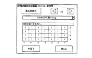
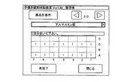
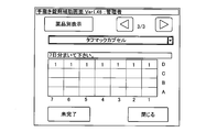
- FIGS. 19 to 21 are screens for displaying the number of tablets and the number of tablets in each storage recess 26 of the tray 24 for each tablet. By operating the arrows on the screen, The quantity can be confirmed.
- FIG. 22 is a display screen of the total number of locks for each storage recess 26, and it can be confirmed whether or not there is no mistake in the number of locks finally put into each storage recess 26. Based on these display screens, it is possible to confirm the distribution status of tablets in the case of manual handling.
- a tray handling position b standby position A discharge position B reception start position C reception end position D collection position 11 tablet packaging device 12 frame 13 tablet storage section 14 packaging section 15 storage section 16 tablet cassette 17 tablet feeder 18 armor door shutter 19 Discharge chute 20 Receiving port 21 Discharge port 22 Cover lid 23 Drawer 24 Tray 25 Lid sheet 26 Storage recess 27a Side wall 27b Side wall 27c Partition wall 27d Groove 28 29 29 Tablet 30 Mounting table 30a Tray support rib 31 Adhesive 31a Breaking line 31b Breaking line 31b 32 Seven-day display 33 Date display 34 In-dose display 35 Prescription display 37 Carrier 38 Shutter 39 Drive device 40 Opening and closing device 41 Vertical motion device 42 Motor for vertical motion 43 Belt 44 Rotating shaft 45 Eccentric cam wheel 46 Cam follower 47 shaft 48 fixed bracket plate 49 movable bracket plate 51 long hole 52 fixing screw 53, 54 adjusting plate 55, 56 adjusting bolt 57 mounting base support member 58 guide pin 59 contact plate 60 coil spring 61 sleeve 62 retaining member 64 dust receiving tray 65 frame 66 Partition
Landscapes
- Engineering & Computer Science (AREA)
- Mechanical Engineering (AREA)
- Health & Medical Sciences (AREA)
- Life Sciences & Earth Sciences (AREA)
- Animal Behavior & Ethology (AREA)
- General Health & Medical Sciences (AREA)
- Public Health (AREA)
- Veterinary Medicine (AREA)
- Basic Packing Technique (AREA)
- Medical Preparation Storing Or Oral Administration Devices (AREA)
- Supply Of Fluid Materials To The Packaging Location (AREA)
Abstract
Description
b 待機位置
A 排出位置
B 受け取り開始位置
C 受け取り終了位置
D 回収位置
11 錠剤分包装置
12 フレーム
13 錠剤収納部
14 分包部
15 収納部
16 錠剤カセット
17 錠剤フィーダ
18 鎧戸式シャッター
19 払出しシュート
20 受け口
21 払出し口
22 カバー蓋
23 引出し
24 トレー
25 蓋シート
26 収納凹部
27a 側壁
27b 側壁
27c 区画壁
27d 溝
28 皺
29 錠剤
30 載置台
30a トレー支持リブ
31 粘着剤
31a 破断線
31b 破断除去部
32 七曜表示
33 日付表示
34 服用時表示
35 処方表示
37 キャリヤ
38 シャッター
39 駆動装置
40 開閉装置
41 上下動装置
42 上下動用モータ
43 ベルト
44 回転軸
45 偏心カム輪
46 カムフォロア
47 軸受
48 固定ブラケット板
49 可動ブラケット板
51 長穴
52 固定ねじ
53、54 調節板
55、56 調節ボルト
57 載置台支持部材
58 ガイドピン
59 接触板
60 コイルバネ
61 スリーブ
62 抜け止め部材
64 ゴミ受けトレー
65 枠
66 区画壁
67 区画室
68 ブラシ
69 角穴
70 ブラケット
70a 上バー
71 シャッターガイド部材
72 ガイドローラ
74 連結辺
75 固定ねじ
77 ガイド辺
78 係合辺
79 スリット
80 スリット
81 切欠き部
82 差し込み口
83 ゴミ
84 Y方向駆動モータ
85 X方向駆動モータ
86 Y方向駆動ベルト
87 ケーシング
88 X方向駆動ベルト
89 Y方向スライダー
90 連動軸
91 Y方向ガイドバー
92 ブラケット
93 スライダーホルダー
94 ベルト挟持部材
95 X方向スライダー
96 X方向ガイドバー
102 回収トレー
103 トレー受け凹部
104 底板
105 クッションシート
110 錠部材
111 固定軸
112 レバー
113 フック
114 軸
115 内部バネ
116 L形金具
117 係合部材
118 固定ねじ
123 シャッター開閉モータ
124 歯車
125 連動軸
126 シャッター開閉用ベルト
127 ガイドバー
128 スライダー
129 係合バー
130 バネ装置
131 軸
132 帯状バネ
133 固定継手部材
134 支持部材
135 バネケース
Claims (11)
- 処方に従って払い出される錠剤の払出し口の下部に分包部が設けられ、前記分包部に複数の行と列に区画された所要数の収納凹部を有するトレーが載置され、前記払出し口から払い出される錠剤を前記各収納凹部に分配・収納するようにした錠剤分包装置において、前記分包部は、前記トレーの載置台とその載置台の移動装置、前記トレーの収納凹部の位置に合致し得る上下開放の区画室を備えたキャリヤとそのキャリヤの駆動装置、及び前記キャリヤの底面に設けられ前記区画室を開閉するシャッターとそのシャッターの開閉装置から成り、前記載置台の移動装置は前記キャリヤの移動とタイミングを合わせて当該載置台をトレー扱い位置と待機位置との間を移動させ、前記キャリヤの駆動装置は、当該キャリヤを前記待機位置上部に設定された排出位置を原位置として、前記払出し口下部に設定された錠剤の受け取り開始位置と受け取り終了位置を順に経て原位置に戻る搬送工程を実行する途中において前記受け取り開始位置から受け取り終了位置に至るまでの間に前記キャリヤの各区画室を順次払出し口の下方に移動させ錠剤を受け取る受け取り工程を実行し、前記シャッターの開閉装置は、前記キャリヤが受け取り終了位置から排出位置に戻った際に当該シャッターを開放し、それ以外は閉鎖することを特徴とする錠剤分包装置。
- 前記載置台の移動装置が、前記分包部に対して出し入れ自在に設けられた引出しによって構成され、前記引出しの内部に前記の載置台が設置され、前記引出しが引き出された際に前記載置台が分包部外部のトレー扱い位置にあり、押し込まれた際に分包部内部の待機位置にあるように設定されたことを特徴とする請求項1に記載の錠剤分包装置。
- 前記載置台が上下動装置によって支持され、前記上下動装置は、前記待機位置においてキャリヤから錠剤を受け取る際に作動され、これによって前記載置台上のトレーを前記キャリヤの底部に接近又は接触させることを特徴とする請求項1又は2に記載の錠剤分包装置。
- 前記上下動装置にダンパーが設けられ、そのダンパーの自由端部を前記載置台底面に当接させた請求項3に記載の錠剤分包装置。
- 前記キャリヤの駆動装置が、前記キャリヤを水平面内のX方向と、これと直交するY方向に移動させるXY駆動機構によって構成されたことを特徴とする請求項1から4のいずれかに記載の錠剤分包装置。
- 前記XY駆動機構は、Y方向駆動モータ、X方向駆動モータ、前記分包部の左右2個所に設置されたY方向駆動ベルト、前記2個所のY方向駆動ベルト間に支持されたケーシング及びX方向駆動ベルトによって構成され、前記X方向駆動モータ及びX方向駆動ベルトが前記ケーシングに搭載され、前記Y方向駆動ベルトが前記Y方向駆動モータによって、前記X方向駆動モータが前記X方向駆動モータによってそれぞれ駆動され、前記キャリヤが、当該キャリヤに設けられたブラケットを介して前記X方向駆動ベルトに取り付けられたX方向スライダーに連結されたことを特徴とする請求項5に記載の錠剤分包装置。
- 前記キャリヤに対し前記ブラケットが着脱可能に係合され、当該キャリヤが前記ブラケットに対し錠部材によって着脱可能に連結されたことを特徴とする請求項6に記載の錠剤分包装置。
- 前記受け取り位置から前記排出位置に戻ったキャリヤの各区画室に錠剤の配給ミスがあった際は、シャッターの開放前に当該キャリヤを回収位置に移動させ、その回収位置においてシャッターを開放し内部の錠剤を全て回収トレーに排出することを特徴とする請求項1から7のいずれかに記載の錠剤分包装置。
- 前記回収トレーの内底面にクッションシートが敷かれたことを特徴とする請求項8記載の錠剤分包装置。
- 前記キャリヤの底面にシャッターガイド部材が設けられ、前記シャッターガイド部材に前記キャリヤの区画室に合致するよう配置された穴が設けられ、前記シャッターガイド部材とキャリヤ底面との間に前記シャッターが前後方向にスライド自在に介在され、前記シャッターの後端部に係合辺が設けられたことを特徴とする請求項1から9のいずれかに記載の錠剤分包装置。
- 前記キャリヤの後端部に前記シャッターの上面に接触するようにブラシが設けられ、前記シャッターガイド部材に前記ブラシに沿ってゴミ排出スリットが設けられ、前記シャッターの前端辺にその全幅に近い範囲の切欠き部、後端辺に沿った部分にその全幅に近い長さのシャッタースリットがそれぞれ設けられ、前記シャッターの全開時に前記切欠き部が前記ゴミ排出スリット上に合致し、前記シャッターの全閉時に前記シャッタースリットが前記ゴミ排出スリットに合致するよう前記ゴミ排出スリットと、切欠き部及びシャッタースリットの位置関係が設定されたことを特徴とする請求項1から10のいずれかに記載の錠剤分包装置。
Priority Applications (5)
| Application Number | Priority Date | Filing Date | Title |
|---|---|---|---|
| NZ612052A NZ612052A (en) | 2010-11-26 | 2011-11-25 | Tablet packaging device |
| JP2012545802A JP5870931B2 (ja) | 2010-11-26 | 2011-11-25 | 錠剤分包装置及び錠剤の分包方法 |
| AU2011332677A AU2011332677B2 (en) | 2010-11-26 | 2011-11-25 | Tablet packaging device |
| US13/847,279 US9428288B2 (en) | 2010-11-26 | 2013-03-19 | Tablet packaging device |
| US15/147,352 US10647455B2 (en) | 2010-11-26 | 2016-05-05 | Tablet packaging device |
Applications Claiming Priority (2)
| Application Number | Priority Date | Filing Date | Title |
|---|---|---|---|
| JP2010-263559 | 2010-11-26 | ||
| JP2010263559 | 2010-11-26 |
Related Child Applications (1)
| Application Number | Title | Priority Date | Filing Date |
|---|---|---|---|
| US13/847,279 Continuation US9428288B2 (en) | 2010-11-26 | 2013-03-19 | Tablet packaging device |
Publications (1)
| Publication Number | Publication Date |
|---|---|
| WO2012070643A1 true WO2012070643A1 (ja) | 2012-05-31 |
Family
ID=46145980
Family Applications (1)
| Application Number | Title | Priority Date | Filing Date |
|---|---|---|---|
| PCT/JP2011/077179 Ceased WO2012070643A1 (ja) | 2010-11-26 | 2011-11-25 | 錠剤分包装置 |
Country Status (5)
| Country | Link |
|---|---|
| US (2) | US9428288B2 (ja) |
| JP (1) | JP5870931B2 (ja) |
| AU (1) | AU2011332677B2 (ja) |
| NZ (1) | NZ612052A (ja) |
| WO (1) | WO2012070643A1 (ja) |
Cited By (21)
| Publication number | Priority date | Publication date | Assignee | Title |
|---|---|---|---|---|
| US9150119B2 (en) | 2013-03-15 | 2015-10-06 | Aesynt Incorporated | Apparatuses, systems, and methods for anticipating and delivering medications from a central pharmacy to a patient using a track based transport system |
| JP2016523152A (ja) * | 2013-06-26 | 2016-08-08 | ケアフュージョン・ジャーマニー・326・ゲーエムベーハー | 自動保存システムから医薬品パックを順次供給する排出/投入ステーションを用いて、複数の受承用コンパートメントを有する輸送ボックスを確実に充填するための方法、及び上記方法のための排出/投入ステーション |
| JP2016528111A (ja) * | 2013-06-20 | 2016-09-15 | ケアフュージョン・ジャーマニー・326・ゲーエムベーハー | 自動薬剤分包デバイスのための輸送デバイス |
| US9511945B2 (en) | 2012-10-12 | 2016-12-06 | Aesynt Incorporated | Apparatuses, systems, and methods for transporting medications from a central pharmacy to a patient in a healthcare facility |
| JP2017047964A (ja) * | 2015-09-04 | 2017-03-09 | 株式会社松尾製作所 | 除包システム |
| WO2017043430A1 (ja) * | 2015-09-08 | 2017-03-16 | 株式会社湯山製作所 | 錠剤分包装置 |
| WO2017111024A1 (ja) * | 2015-12-24 | 2017-06-29 | 株式会社タカゾノテクノロジー | 薬剤供給装置及びこれを備えた薬剤包装装置 |
| JP2018043767A (ja) * | 2016-09-14 | 2018-03-22 | 株式会社タカゾノテクノロジー | 薬剤供給装置 |
| JP2018043766A (ja) * | 2016-09-14 | 2018-03-22 | 株式会社タカゾノテクノロジー | 薬剤供給装置 |
| JPWO2017002713A1 (ja) * | 2015-06-29 | 2018-04-19 | 株式会社湯山製作所 | 薬剤払出装置 |
| WO2018207868A1 (ja) | 2017-05-12 | 2018-11-15 | 株式会社湯山製作所 | 薬剤払出装置、薬剤払出装置の制御プログラム、および制御プログラムを記録した記録媒体 |
| WO2019172317A1 (ja) * | 2018-03-09 | 2019-09-12 | 株式会社湯山製作所 | 錠剤分包装置 |
| JP2020022810A (ja) * | 2019-11-01 | 2020-02-13 | 株式会社タカゾノテクノロジー | 薬剤包装装置および薬剤供給装置 |
| JP2021076381A (ja) * | 2019-11-05 | 2021-05-20 | ニプロ株式会社 | 分包シートの検査装置 |
| CN113834704A (zh) * | 2020-06-23 | 2021-12-24 | 上海伯顿医疗设备有限公司 | 一种全自动旋转料箱雾化器式染色封片一体机 |
| US11273103B1 (en) | 2021-06-22 | 2022-03-15 | Vmi Holland B.V. | Method, computer program product and dispensing device for dispensing discrete medicaments |
| CN114454539A (zh) * | 2022-02-14 | 2022-05-10 | 安徽金太阳生化药业有限公司 | 一种制药用连续化压片设备 |
| KR20220135101A (ko) * | 2021-03-29 | 2022-10-06 | (주)크레템 | 블리스터 팩용 약제 분배 유닛 및 이를 구비한 약제의 블리스터 팩킹 장치 |
| US11498761B1 (en) | 2021-06-22 | 2022-11-15 | Vmi Holland B.V. | Method for dispensing discrete medicaments, a test station for testing a feeder unit, and a method for determining a fill level of a feeder unit |
| US11673700B2 (en) | 2021-06-22 | 2023-06-13 | Vmi Holland B.V. | Device and methods for packaging medicaments with fault detection |
| US12521315B2 (en) | 2021-06-22 | 2026-01-13 | Vmi Holland B.V. | Method, computer program product and dispensing device for dispensing discrete medicaments |
Families Citing this family (12)
| Publication number | Priority date | Publication date | Assignee | Title |
|---|---|---|---|---|
| NL2012310C2 (en) * | 2014-02-21 | 2015-08-25 | Global Factories Total Engineering And Mfg B V | Method of and device for receiving and checking individualized doses of medicines. |
| US9665135B2 (en) | 2014-03-07 | 2017-05-30 | Ergotron, Inc. | Device storage cabinet |
| KR20180105804A (ko) * | 2017-03-16 | 2018-10-01 | (주)제이브이엠 | 블리스터 포장장치 및 블리스터 팩 포장방법 |
| NL2019530B1 (nl) * | 2017-09-12 | 2019-03-27 | Canister Dev B V | Inrichting voor verpakken van gedoseerde hoeveelheden vaste medicijnen |
| CN108820397B (zh) * | 2018-07-24 | 2024-06-21 | 郑州协力建工设备有限公司 | 侧出料卧式打包机 |
| JP7151973B2 (ja) * | 2019-03-13 | 2022-10-12 | 株式会社トーショー | 調剤台 |
| DE102019132870A1 (de) * | 2019-12-03 | 2021-06-10 | Gebr. Willach Gmbh | Befüllvorrichtung für Verpackungen, Verpackungsvorrichtung sowie Verfahren zur Befüllung von Verpackungen |
| US12534240B2 (en) | 2020-04-01 | 2026-01-27 | Rxsafe Llc | Automatic packager for medications |
| EP4137416A4 (en) * | 2020-04-17 | 2024-05-01 | Yuyama Mfg. Co., Ltd. | DRUG EJECTION DEVICE AND METHOD FOR CONTROLLING A DRUG EJECTION DEVICE |
| WO2022215338A1 (ja) * | 2021-04-07 | 2022-10-13 | Phc株式会社 | 薬剤供給装置 |
| US12036185B2 (en) | 2021-07-19 | 2024-07-16 | Optum, Inc. | System and method to count pills |
| CN113995235B (zh) * | 2021-10-29 | 2023-03-10 | 合肥工业大学 | 一种适合会计学教学使用的可移动式实验桌 |
Citations (8)
| Publication number | Priority date | Publication date | Assignee | Title |
|---|---|---|---|---|
| JPH05170201A (ja) * | 1991-12-18 | 1993-07-09 | Nippon Eranko Kk | 硬質ゼラチンカプセルへの錠剤充填装置 |
| JPH0710102A (ja) * | 1993-06-28 | 1995-01-13 | Tokyo Shokai:Kk | 錠剤分包機の包装装置 |
| JP2001213401A (ja) * | 2000-02-04 | 2001-08-07 | Takazono Sangyo Kk | 錠剤自動振り撒き装置 |
| JP2006232351A (ja) * | 2005-02-25 | 2006-09-07 | Yuyama Manufacturing Co Ltd | 薬剤包装装置 |
| WO2009023632A1 (en) * | 2007-08-13 | 2009-02-19 | Mts Medication Technologies, Inc. | High speed automated filling of solid pharmaceutical product packaging via a conveyor system |
| JP2009096557A (ja) * | 2007-09-27 | 2009-05-07 | Yuyama Manufacturing Co Ltd | 手撒き薬剤供給装置、薬剤の手撒き方法、及び、薬剤分包装置 |
| US7587878B2 (en) * | 2008-01-25 | 2009-09-15 | Jvm Co., Ltd. | Tablet distribution apparatus for auxiliary trays and driving method thereof |
| JP2010155089A (ja) * | 2010-02-02 | 2010-07-15 | Takazono Sangyo Co Ltd | 薬剤供給機構及び薬剤分包装置 |
Family Cites Families (26)
| Publication number | Priority date | Publication date | Assignee | Title |
|---|---|---|---|---|
| US3464180A (en) * | 1966-10-07 | 1969-09-02 | Potter Instrument Co Inc | Straight edge,beam or other similar article of manufacture |
| JPS6315164A (ja) * | 1986-07-07 | 1988-01-22 | Tosoh Corp | 生化学分析装置のテストパツク選択供給装置 |
| US5481855A (en) * | 1994-09-27 | 1996-01-09 | Yuyama; Shoji | Tablet packing device and method for controlling the same |
| JPH09215728A (ja) * | 1996-02-07 | 1997-08-19 | Yuyama Seisakusho:Kk | 錠剤払出し方法 |
| AUPO842897A0 (en) | 1997-08-06 | 1997-08-28 | Imaging Technologies Pty Ltd | Product vending |
| US6116461A (en) * | 1998-05-29 | 2000-09-12 | Pyxis Corporation | Method and apparatus for the dispensing of drugs |
| US6925774B2 (en) * | 2000-03-31 | 2005-08-09 | Mts Medication Technologies, Inc. | Compact structure for automatically filling solid pharmaceutical product packages |
| US7334379B1 (en) * | 2000-11-01 | 2008-02-26 | Mts Medication Technologies, Inc. | Automated solid pharmaceutical product packaging machine |
| GB0108215D0 (en) * | 2001-04-02 | 2001-05-23 | Glaxo Group Ltd | Medicament dispenser |
| US6508279B2 (en) * | 2001-04-23 | 2003-01-21 | Medical Technology Systems, Inc. | Automated solid pharmaceutical product packaging machine with parallel filling and sealing capability |
| JP4231407B2 (ja) * | 2001-09-24 | 2009-02-25 | アイエムエックス ラブズ インコーポレイテッド | 化粧品カスタム調合用の装置および方法 |
| US7040077B2 (en) * | 2001-09-28 | 2006-05-09 | Yuyama Mfg. Co. Ltd. | Medicine packing apparatus |
| US7264136B2 (en) * | 2003-08-26 | 2007-09-04 | Concept Medical Technologies, Inc. | Medication dispensing method and apparatus |
| US8468777B2 (en) * | 2005-02-16 | 2013-06-25 | Yuyama Mfg. Co., Ltd. | Tablet filling device |
| JP4821130B2 (ja) * | 2005-02-16 | 2011-11-24 | 株式会社湯山製作所 | 錠剤充填装置 |
| KR100659909B1 (ko) * | 2005-08-25 | 2006-12-20 | (주)제이브이엠 | 약제 자동 포장 시스템 |
| JP4910341B2 (ja) * | 2005-09-12 | 2012-04-04 | 株式会社湯山製作所 | 錠剤充填装置 |
| US7389632B2 (en) * | 2006-06-10 | 2008-06-24 | Uhlmann Pac-Systeme Gmbh & Co. Kg | Apparatus for distributing small objects in a fill station |
| KR100787808B1 (ko) * | 2006-12-22 | 2007-12-21 | (주)제이브이엠 | 도어락킹부를 갖는 약제 자동 포장기 |
| US8818552B2 (en) * | 2007-07-10 | 2014-08-26 | Carefusion 303, Inc. | Point-of-care medication dispensing |
| JP4253357B1 (ja) | 2007-09-27 | 2009-04-08 | 株式会社湯山製作所 | 手撒き薬剤供給装置、薬剤の手撒き方法、及び、薬剤分包装置 |
| EP2062822A1 (de) * | 2007-11-24 | 2009-05-27 | UHLMANN PAC-SYSTEME GmbH & Co. KG | Verfahren und Vorrichtung zum individuellen Befüllen von Blistern |
| US7908827B2 (en) * | 2008-06-27 | 2011-03-22 | Qem, Inc. | Method and apparatus for automatically filling prescriptions using interchangeable platens |
| US7883077B2 (en) * | 2008-06-27 | 2011-02-08 | QEM, Inc, | Low-profile X-Y table |
| US8261939B2 (en) * | 2010-05-11 | 2012-09-11 | Qem, Inc. | Pill dispenser canister having dual reservoirs |
| US9501626B2 (en) * | 2013-05-29 | 2016-11-22 | Dafang Zhang | Smart automated pill dispenser |
-
2011
- 2011-11-25 WO PCT/JP2011/077179 patent/WO2012070643A1/ja not_active Ceased
- 2011-11-25 NZ NZ612052A patent/NZ612052A/en unknown
- 2011-11-25 AU AU2011332677A patent/AU2011332677B2/en active Active
- 2011-11-25 JP JP2012545802A patent/JP5870931B2/ja active Active
-
2013
- 2013-03-19 US US13/847,279 patent/US9428288B2/en active Active
-
2016
- 2016-05-05 US US15/147,352 patent/US10647455B2/en active Active
Patent Citations (8)
| Publication number | Priority date | Publication date | Assignee | Title |
|---|---|---|---|---|
| JPH05170201A (ja) * | 1991-12-18 | 1993-07-09 | Nippon Eranko Kk | 硬質ゼラチンカプセルへの錠剤充填装置 |
| JPH0710102A (ja) * | 1993-06-28 | 1995-01-13 | Tokyo Shokai:Kk | 錠剤分包機の包装装置 |
| JP2001213401A (ja) * | 2000-02-04 | 2001-08-07 | Takazono Sangyo Kk | 錠剤自動振り撒き装置 |
| JP2006232351A (ja) * | 2005-02-25 | 2006-09-07 | Yuyama Manufacturing Co Ltd | 薬剤包装装置 |
| WO2009023632A1 (en) * | 2007-08-13 | 2009-02-19 | Mts Medication Technologies, Inc. | High speed automated filling of solid pharmaceutical product packaging via a conveyor system |
| JP2009096557A (ja) * | 2007-09-27 | 2009-05-07 | Yuyama Manufacturing Co Ltd | 手撒き薬剤供給装置、薬剤の手撒き方法、及び、薬剤分包装置 |
| US7587878B2 (en) * | 2008-01-25 | 2009-09-15 | Jvm Co., Ltd. | Tablet distribution apparatus for auxiliary trays and driving method thereof |
| JP2010155089A (ja) * | 2010-02-02 | 2010-07-15 | Takazono Sangyo Co Ltd | 薬剤供給機構及び薬剤分包装置 |
Cited By (43)
| Publication number | Priority date | Publication date | Assignee | Title |
|---|---|---|---|---|
| US10850926B2 (en) | 2012-10-12 | 2020-12-01 | Omnicell, Inc. | Apparatuses, systems, and methods for transporting medications from a central pharmacy to a patient in a healthcare facility |
| US9511945B2 (en) | 2012-10-12 | 2016-12-06 | Aesynt Incorporated | Apparatuses, systems, and methods for transporting medications from a central pharmacy to a patient in a healthcare facility |
| US10315851B2 (en) | 2012-10-12 | 2019-06-11 | Aesynt Incorporated | Apparatuses, systems, and methods for transporting medications from a central pharmacy to a patient in a healthcare facility |
| US11694782B2 (en) | 2012-10-12 | 2023-07-04 | Omnicell, Inc. | Apparatuses, systems, and methods for transporting medications from a central pharmacy to a patient in a healthcare facility |
| US10518981B2 (en) | 2012-10-12 | 2019-12-31 | Aesynt Incorporated | Apparatuses, systems, and methods for transporting medications from a central pharmacy to a patient in a healthcare facility |
| US10029856B2 (en) | 2012-10-12 | 2018-07-24 | Aesynt Incorporated | Apparatuses, systems, and methods for transporting medications from a central pharmacy to a patient in a healthcare facility |
| US9150119B2 (en) | 2013-03-15 | 2015-10-06 | Aesynt Incorporated | Apparatuses, systems, and methods for anticipating and delivering medications from a central pharmacy to a patient using a track based transport system |
| JP2016528111A (ja) * | 2013-06-20 | 2016-09-15 | ケアフュージョン・ジャーマニー・326・ゲーエムベーハー | 自動薬剤分包デバイスのための輸送デバイス |
| US10406073B2 (en) | 2013-06-20 | 2019-09-10 | Carefusion Germany 326 Gmbh | Transporting device for an automated drug-dosing device |
| JP2016523152A (ja) * | 2013-06-26 | 2016-08-08 | ケアフュージョン・ジャーマニー・326・ゲーエムベーハー | 自動保存システムから医薬品パックを順次供給する排出/投入ステーションを用いて、複数の受承用コンパートメントを有する輸送ボックスを確実に充填するための方法、及び上記方法のための排出/投入ステーション |
| US10625885B2 (en) | 2015-06-29 | 2020-04-21 | Yuyama Mfg. Co., Ltd. | Medicine dispensing apparatus |
| JPWO2017002713A1 (ja) * | 2015-06-29 | 2018-04-19 | 株式会社湯山製作所 | 薬剤払出装置 |
| JP2017047964A (ja) * | 2015-09-04 | 2017-03-09 | 株式会社松尾製作所 | 除包システム |
| KR20180050659A (ko) | 2015-09-08 | 2018-05-15 | 가부시키가이샤 유야마 세이사쿠쇼 | 정제 분배포장 장치 |
| WO2017043430A1 (ja) * | 2015-09-08 | 2017-03-16 | 株式会社湯山製作所 | 錠剤分包装置 |
| WO2017111024A1 (ja) * | 2015-12-24 | 2017-06-29 | 株式会社タカゾノテクノロジー | 薬剤供給装置及びこれを備えた薬剤包装装置 |
| JP2018043766A (ja) * | 2016-09-14 | 2018-03-22 | 株式会社タカゾノテクノロジー | 薬剤供給装置 |
| JP2018043767A (ja) * | 2016-09-14 | 2018-03-22 | 株式会社タカゾノテクノロジー | 薬剤供給装置 |
| WO2018207868A1 (ja) | 2017-05-12 | 2018-11-15 | 株式会社湯山製作所 | 薬剤払出装置、薬剤払出装置の制御プログラム、および制御プログラムを記録した記録媒体 |
| JP7358686B2 (ja) | 2017-05-12 | 2023-10-11 | 株式会社湯山製作所 | 薬剤払出装置、薬剤払出装置の制御プログラム、および制御プログラムを記録した記録媒体 |
| JPWO2018207868A1 (ja) * | 2017-05-12 | 2020-03-12 | 株式会社湯山製作所 | 薬剤払出装置、薬剤払出装置の制御プログラム、および制御プログラムを記録した記録媒体 |
| JPWO2019172317A1 (ja) * | 2018-03-09 | 2020-10-22 | 株式会社湯山製作所 | 錠剤分包装置 |
| US11897647B2 (en) | 2018-03-09 | 2024-02-13 | Yuyama Mfg. Co., Ltd. | Individual packaging device for tablets |
| KR102666501B1 (ko) | 2018-03-09 | 2024-05-17 | 가부시키가이샤 유야마 세이사쿠쇼 | 정제 분포 장치 |
| KR20200128674A (ko) * | 2018-03-09 | 2020-11-16 | 가부시키가이샤 유야마 세이사쿠쇼 | 정제 분포 장치 |
| AU2019230666B2 (en) * | 2018-03-09 | 2024-01-18 | Yuyama Mfg. Co., Ltd. | Individual packaging device for tablets |
| WO2019172317A1 (ja) * | 2018-03-09 | 2019-09-12 | 株式会社湯山製作所 | 錠剤分包装置 |
| US11325728B2 (en) | 2018-03-09 | 2022-05-10 | Yuyama Mfg. Co., Ltd. | Individual packaging device for tablets |
| JP2020022810A (ja) * | 2019-11-01 | 2020-02-13 | 株式会社タカゾノテクノロジー | 薬剤包装装置および薬剤供給装置 |
| JP2021076381A (ja) * | 2019-11-05 | 2021-05-20 | ニプロ株式会社 | 分包シートの検査装置 |
| JP7322665B2 (ja) | 2019-11-05 | 2023-08-08 | ニプロ株式会社 | 分包シートの検査装置 |
| CN113834704A (zh) * | 2020-06-23 | 2021-12-24 | 上海伯顿医疗设备有限公司 | 一种全自动旋转料箱雾化器式染色封片一体机 |
| KR102531180B1 (ko) * | 2021-03-29 | 2023-05-10 | (주)크레템 | 블리스터 팩용 약제 분배 유닛 및 이를 구비한 약제의 블리스터 팩킹 장치 |
| KR20220135101A (ko) * | 2021-03-29 | 2022-10-06 | (주)크레템 | 블리스터 팩용 약제 분배 유닛 및 이를 구비한 약제의 블리스터 팩킹 장치 |
| WO2022211423A1 (ko) * | 2021-03-29 | 2022-10-06 | (주)크레템 | 블리스터 팩용 약제 분배 유닛 및 이를 구비한 약제의 블리스터 팩킹 장치 |
| US11673700B2 (en) | 2021-06-22 | 2023-06-13 | Vmi Holland B.V. | Device and methods for packaging medicaments with fault detection |
| US11498761B1 (en) | 2021-06-22 | 2022-11-15 | Vmi Holland B.V. | Method for dispensing discrete medicaments, a test station for testing a feeder unit, and a method for determining a fill level of a feeder unit |
| US11273103B1 (en) | 2021-06-22 | 2022-03-15 | Vmi Holland B.V. | Method, computer program product and dispensing device for dispensing discrete medicaments |
| US11925604B2 (en) | 2021-06-22 | 2024-03-12 | Vmi Holland B.V. | Method, computer program product and dispensing device for dispensing discrete medicaments |
| US11931317B2 (en) | 2021-06-22 | 2024-03-19 | Vmi Holland B.V. | Method, computer program product and dispensing device for dispensing discrete medicaments |
| US12521315B2 (en) | 2021-06-22 | 2026-01-13 | Vmi Holland B.V. | Method, computer program product and dispensing device for dispensing discrete medicaments |
| CN114454539A (zh) * | 2022-02-14 | 2022-05-10 | 安徽金太阳生化药业有限公司 | 一种制药用连续化压片设备 |
| CN114454539B (zh) * | 2022-02-14 | 2024-05-07 | 安徽金太阳生化药业有限公司 | 一种制药用连续化压片设备 |
Also Published As
| Publication number | Publication date |
|---|---|
| JPWO2012070643A1 (ja) | 2014-05-19 |
| AU2011332677B2 (en) | 2017-04-20 |
| JP5870931B2 (ja) | 2016-03-01 |
| US20130212987A1 (en) | 2013-08-22 |
| NZ612052A (en) | 2014-10-31 |
| US10647455B2 (en) | 2020-05-12 |
| US20160244192A1 (en) | 2016-08-25 |
| AU2011332677A1 (en) | 2013-07-11 |
| AU2011332677A2 (en) | 2014-02-20 |
| US9428288B2 (en) | 2016-08-30 |
Similar Documents
| Publication | Publication Date | Title |
|---|---|---|
| JP5870931B2 (ja) | 錠剤分包装置及び錠剤の分包方法 | |
| US7861491B2 (en) | Medicine dispensing/packaging apparatus | |
| JP4121190B2 (ja) | 調剤システム | |
| JP5434420B2 (ja) | 薬剤払出装置及び薬剤払出方法 | |
| JP6798639B2 (ja) | 錠剤分包装置 | |
| JP5429311B2 (ja) | 薬剤払出方法 | |
| US7721508B2 (en) | Tablet filling device | |
| TWI685335B (zh) | 藥劑配發裝置 | |
| KR20010077911A (ko) | 약제분포장치 | |
| CN101166666B (zh) | 药品分包装置 | |
| TWI901670B (zh) | 藥劑排出裝置及藥劑排出裝置的控制方法 | |
| JPWO2017043430A1 (ja) | 錠剤分包装置 | |
| KR100727422B1 (ko) | 약제분포장치 | |
| JP5530112B2 (ja) | 調剤装置の薬品ストック構造 | |
| JP2002019705A (ja) | 薬剤分包機 | |
| CN117460489A (zh) | 药品分包机 | |
| JP5507098B2 (ja) | 調剤装置 | |
| JP4093434B2 (ja) | 調剤用薬剤払出装置 | |
| JP2000024086A (ja) | 調剤用薬剤払出装置 | |
| JP5967590B2 (ja) | 調剤装置のシート押し出し機構及び方法 | |
| KR101652172B1 (ko) | 의약품 불출 장치 | |
| JP5783520B2 (ja) | 調剤装置のシート押し出し機構 |
Legal Events
| Date | Code | Title | Description |
|---|---|---|---|
| 121 | Ep: the epo has been informed by wipo that ep was designated in this application |
Ref document number: 11842630 Country of ref document: EP Kind code of ref document: A1 |
|
| WWE | Wipo information: entry into national phase |
Ref document number: 2012545802 Country of ref document: JP |
|
| NENP | Non-entry into the national phase |
Ref country code: DE |
|
| ENP | Entry into the national phase |
Ref document number: 2011332677 Country of ref document: AU Date of ref document: 20111125 Kind code of ref document: A |
|
| 122 | Ep: pct application non-entry in european phase |
Ref document number: 11842630 Country of ref document: EP Kind code of ref document: A1 |