WO2012067156A1 - 熱伝導部材 - Google Patents
熱伝導部材 Download PDFInfo
- Publication number
- WO2012067156A1 WO2012067156A1 PCT/JP2011/076430 JP2011076430W WO2012067156A1 WO 2012067156 A1 WO2012067156 A1 WO 2012067156A1 JP 2011076430 W JP2011076430 W JP 2011076430W WO 2012067156 A1 WO2012067156 A1 WO 2012067156A1
- Authority
- WO
- WIPO (PCT)
- Prior art keywords
- fluid
- ceramic body
- cylindrical ceramic
- heat
- metal tube
- Prior art date
Links
- 229910052751 metal Inorganic materials 0.000 claims abstract description 149
- 239000002184 metal Substances 0.000 claims abstract description 149
- 239000012530 fluid Substances 0.000 claims abstract description 106
- 239000000919 ceramic Substances 0.000 claims abstract description 96
- 239000000463 material Substances 0.000 claims abstract description 52
- 238000010438 heat treatment Methods 0.000 claims abstract description 14
- 230000002093 peripheral effect Effects 0.000 claims description 45
- OKTJSMMVPCPJKN-UHFFFAOYSA-N Carbon Chemical compound [C] OKTJSMMVPCPJKN-UHFFFAOYSA-N 0.000 claims description 40
- 229910002804 graphite Inorganic materials 0.000 claims description 40
- 239000010439 graphite Substances 0.000 claims description 40
- 229910010271 silicon carbide Inorganic materials 0.000 claims description 39
- HBMJWWWQQXIZIP-UHFFFAOYSA-N silicon carbide Chemical compound [Si+]#[C-] HBMJWWWQQXIZIP-UHFFFAOYSA-N 0.000 claims description 38
- 238000005192 partition Methods 0.000 claims description 31
- 230000008878 coupling Effects 0.000 abstract 1
- 238000010168 coupling process Methods 0.000 abstract 1
- 238000005859 coupling reaction Methods 0.000 abstract 1
- 238000000034 method Methods 0.000 description 20
- 239000007789 gas Substances 0.000 description 17
- 238000012546 transfer Methods 0.000 description 14
- 230000035882 stress Effects 0.000 description 10
- 230000000052 comparative effect Effects 0.000 description 9
- 239000000843 powder Substances 0.000 description 8
- 238000004519 manufacturing process Methods 0.000 description 6
- XLYOFNOQVPJJNP-UHFFFAOYSA-N water Substances O XLYOFNOQVPJJNP-UHFFFAOYSA-N 0.000 description 6
- 239000000853 adhesive Substances 0.000 description 5
- 239000003054 catalyst Substances 0.000 description 5
- 238000010586 diagram Methods 0.000 description 5
- 238000001125 extrusion Methods 0.000 description 5
- 239000007788 liquid Substances 0.000 description 5
- 239000000203 mixture Substances 0.000 description 5
- 239000002245 particle Substances 0.000 description 5
- 230000001070 adhesive effect Effects 0.000 description 4
- 239000004927 clay Substances 0.000 description 4
- 239000010949 copper Substances 0.000 description 4
- 230000007797 corrosion Effects 0.000 description 4
- 238000005260 corrosion Methods 0.000 description 4
- 238000001035 drying Methods 0.000 description 4
- 230000000694 effects Effects 0.000 description 4
- 238000012360 testing method Methods 0.000 description 4
- IJGRMHOSHXDMSA-UHFFFAOYSA-N Atomic nitrogen Chemical compound N#N IJGRMHOSHXDMSA-UHFFFAOYSA-N 0.000 description 3
- RYGMFSIKBFXOCR-UHFFFAOYSA-N Copper Chemical compound [Cu] RYGMFSIKBFXOCR-UHFFFAOYSA-N 0.000 description 3
- 238000001816 cooling Methods 0.000 description 3
- 229910052802 copper Inorganic materials 0.000 description 3
- 238000005238 degreasing Methods 0.000 description 3
- 229910001873 dinitrogen Inorganic materials 0.000 description 3
- 238000010304 firing Methods 0.000 description 3
- 239000010931 gold Substances 0.000 description 3
- 230000006872 improvement Effects 0.000 description 3
- 238000009434 installation Methods 0.000 description 3
- 239000004033 plastic Substances 0.000 description 3
- 230000008569 process Effects 0.000 description 3
- 238000011084 recovery Methods 0.000 description 3
- 229910052710 silicon Inorganic materials 0.000 description 3
- 239000010703 silicon Substances 0.000 description 3
- 239000000758 substrate Substances 0.000 description 3
- 230000008646 thermal stress Effects 0.000 description 3
- XEEYBQQBJWHFJM-UHFFFAOYSA-N Iron Chemical compound [Fe] XEEYBQQBJWHFJM-UHFFFAOYSA-N 0.000 description 2
- PXHVJJICTQNCMI-UHFFFAOYSA-N Nickel Chemical compound [Ni] PXHVJJICTQNCMI-UHFFFAOYSA-N 0.000 description 2
- KDLHZDBZIXYQEI-UHFFFAOYSA-N Palladium Chemical compound [Pd] KDLHZDBZIXYQEI-UHFFFAOYSA-N 0.000 description 2
- 206010037660 Pyrexia Diseases 0.000 description 2
- -1 Si 3 N 4 Chemical compound 0.000 description 2
- BQCADISMDOOEFD-UHFFFAOYSA-N Silver Chemical compound [Ag] BQCADISMDOOEFD-UHFFFAOYSA-N 0.000 description 2
- HCHKCACWOHOZIP-UHFFFAOYSA-N Zinc Chemical compound [Zn] HCHKCACWOHOZIP-UHFFFAOYSA-N 0.000 description 2
- 229910052782 aluminium Inorganic materials 0.000 description 2
- XAGFODPZIPBFFR-UHFFFAOYSA-N aluminium Chemical compound [Al] XAGFODPZIPBFFR-UHFFFAOYSA-N 0.000 description 2
- 239000011230 binding agent Substances 0.000 description 2
- 229910010293 ceramic material Inorganic materials 0.000 description 2
- 238000006243 chemical reaction Methods 0.000 description 2
- 239000000498 cooling water Substances 0.000 description 2
- 230000002349 favourable effect Effects 0.000 description 2
- 230000004907 flux Effects 0.000 description 2
- PCHJSUWPFVWCPO-UHFFFAOYSA-N gold Chemical compound [Au] PCHJSUWPFVWCPO-UHFFFAOYSA-N 0.000 description 2
- 229910052737 gold Inorganic materials 0.000 description 2
- 239000011261 inert gas Substances 0.000 description 2
- 239000012299 nitrogen atmosphere Substances 0.000 description 2
- 229910000510 noble metal Inorganic materials 0.000 description 2
- 230000003647 oxidation Effects 0.000 description 2
- 238000007254 oxidation reaction Methods 0.000 description 2
- BASFCYQUMIYNBI-UHFFFAOYSA-N platinum Chemical compound [Pt] BASFCYQUMIYNBI-UHFFFAOYSA-N 0.000 description 2
- 238000000746 purification Methods 0.000 description 2
- 230000035939 shock Effects 0.000 description 2
- 229910052709 silver Inorganic materials 0.000 description 2
- 239000004332 silver Substances 0.000 description 2
- 229910052725 zinc Inorganic materials 0.000 description 2
- 239000011701 zinc Substances 0.000 description 2
- 229910001369 Brass Inorganic materials 0.000 description 1
- 229910052684 Cerium Inorganic materials 0.000 description 1
- FYYHWMGAXLPEAU-UHFFFAOYSA-N Magnesium Chemical compound [Mg] FYYHWMGAXLPEAU-UHFFFAOYSA-N 0.000 description 1
- KJTLSVCANCCWHF-UHFFFAOYSA-N Ruthenium Chemical compound [Ru] KJTLSVCANCCWHF-UHFFFAOYSA-N 0.000 description 1
- 229910052772 Samarium Inorganic materials 0.000 description 1
- ATJFFYVFTNAWJD-UHFFFAOYSA-N Tin Chemical compound [Sn] ATJFFYVFTNAWJD-UHFFFAOYSA-N 0.000 description 1
- RTAQQCXQSZGOHL-UHFFFAOYSA-N Titanium Chemical compound [Ti] RTAQQCXQSZGOHL-UHFFFAOYSA-N 0.000 description 1
- QCWXUUIWCKQGHC-UHFFFAOYSA-N Zirconium Chemical compound [Zr] QCWXUUIWCKQGHC-UHFFFAOYSA-N 0.000 description 1
- 239000002253 acid Substances 0.000 description 1
- 150000007513 acids Chemical class 0.000 description 1
- 239000003522 acrylic cement Substances 0.000 description 1
- 239000012298 atmosphere Substances 0.000 description 1
- QVGXLLKOCUKJST-UHFFFAOYSA-N atomic oxygen Chemical compound [O] QVGXLLKOCUKJST-UHFFFAOYSA-N 0.000 description 1
- 230000004323 axial length Effects 0.000 description 1
- 229910052788 barium Inorganic materials 0.000 description 1
- DSAJWYNOEDNPEQ-UHFFFAOYSA-N barium atom Chemical compound [Ba] DSAJWYNOEDNPEQ-UHFFFAOYSA-N 0.000 description 1
- 229910052797 bismuth Inorganic materials 0.000 description 1
- JCXGWMGPZLAOME-UHFFFAOYSA-N bismuth atom Chemical compound [Bi] JCXGWMGPZLAOME-UHFFFAOYSA-N 0.000 description 1
- 239000010951 brass Substances 0.000 description 1
- 238000005219 brazing Methods 0.000 description 1
- 230000003197 catalytic effect Effects 0.000 description 1
- ZMIGMASIKSOYAM-UHFFFAOYSA-N cerium Chemical compound [Ce][Ce][Ce][Ce][Ce][Ce][Ce][Ce][Ce][Ce][Ce][Ce][Ce][Ce][Ce][Ce][Ce][Ce][Ce][Ce][Ce][Ce][Ce][Ce][Ce][Ce][Ce][Ce][Ce][Ce][Ce][Ce][Ce][Ce][Ce][Ce][Ce][Ce] ZMIGMASIKSOYAM-UHFFFAOYSA-N 0.000 description 1
- 229910017052 cobalt Inorganic materials 0.000 description 1
- 239000010941 cobalt Substances 0.000 description 1
- GUTLYIVDDKVIGB-UHFFFAOYSA-N cobalt atom Chemical compound [Co] GUTLYIVDDKVIGB-UHFFFAOYSA-N 0.000 description 1
- 238000002485 combustion reaction Methods 0.000 description 1
- 150000001875 compounds Chemical class 0.000 description 1
- 230000007423 decrease Effects 0.000 description 1
- 238000005516 engineering process Methods 0.000 description 1
- 230000001747 exhibiting effect Effects 0.000 description 1
- 239000000446 fuel Substances 0.000 description 1
- 230000017525 heat dissipation Effects 0.000 description 1
- 238000005470 impregnation Methods 0.000 description 1
- 229910052738 indium Inorganic materials 0.000 description 1
- APFVFJFRJDLVQX-UHFFFAOYSA-N indium atom Chemical compound [In] APFVFJFRJDLVQX-UHFFFAOYSA-N 0.000 description 1
- 230000010354 integration Effects 0.000 description 1
- 229910052742 iron Inorganic materials 0.000 description 1
- 238000005304 joining Methods 0.000 description 1
- 229910052746 lanthanum Inorganic materials 0.000 description 1
- FZLIPJUXYLNCLC-UHFFFAOYSA-N lanthanum atom Chemical compound [La] FZLIPJUXYLNCLC-UHFFFAOYSA-N 0.000 description 1
- 229910052749 magnesium Inorganic materials 0.000 description 1
- 239000011777 magnesium Substances 0.000 description 1
- WPBNNNQJVZRUHP-UHFFFAOYSA-L manganese(2+);methyl n-[[2-(methoxycarbonylcarbamothioylamino)phenyl]carbamothioyl]carbamate;n-[2-(sulfidocarbothioylamino)ethyl]carbamodithioate Chemical compound [Mn+2].[S-]C(=S)NCCNC([S-])=S.COC(=O)NC(=S)NC1=CC=CC=C1NC(=S)NC(=O)OC WPBNNNQJVZRUHP-UHFFFAOYSA-L 0.000 description 1
- 239000002905 metal composite material Substances 0.000 description 1
- 150000002739 metals Chemical class 0.000 description 1
- 238000012986 modification Methods 0.000 description 1
- 230000004048 modification Effects 0.000 description 1
- 229910052759 nickel Inorganic materials 0.000 description 1
- 229910052758 niobium Inorganic materials 0.000 description 1
- 239000010955 niobium Substances 0.000 description 1
- GUCVJGMIXFAOAE-UHFFFAOYSA-N niobium atom Chemical compound [Nb] GUCVJGMIXFAOAE-UHFFFAOYSA-N 0.000 description 1
- 239000001301 oxygen Substances 0.000 description 1
- 229910052760 oxygen Inorganic materials 0.000 description 1
- 229910052763 palladium Inorganic materials 0.000 description 1
- 229910052697 platinum Inorganic materials 0.000 description 1
- 229920006254 polymer film Polymers 0.000 description 1
- 230000036316 preload Effects 0.000 description 1
- 238000012545 processing Methods 0.000 description 1
- 239000013074 reference sample Substances 0.000 description 1
- 239000003870 refractory metal Substances 0.000 description 1
- 229910052703 rhodium Inorganic materials 0.000 description 1
- 239000010948 rhodium Substances 0.000 description 1
- MHOVAHRLVXNVSD-UHFFFAOYSA-N rhodium atom Chemical compound [Rh] MHOVAHRLVXNVSD-UHFFFAOYSA-N 0.000 description 1
- 238000005096 rolling process Methods 0.000 description 1
- 229910052707 ruthenium Inorganic materials 0.000 description 1
- KZUNJOHGWZRPMI-UHFFFAOYSA-N samarium atom Chemical compound [Sm] KZUNJOHGWZRPMI-UHFFFAOYSA-N 0.000 description 1
- 239000000523 sample Substances 0.000 description 1
- 239000007787 solid Substances 0.000 description 1
- 229910052718 tin Inorganic materials 0.000 description 1
- 239000011135 tin Substances 0.000 description 1
- 229910052719 titanium Inorganic materials 0.000 description 1
- 239000010936 titanium Substances 0.000 description 1
- 238000003466 welding Methods 0.000 description 1
- 229910052726 zirconium Inorganic materials 0.000 description 1
Images


Classifications
-
- B—PERFORMING OPERATIONS; TRANSPORTING
- B01—PHYSICAL OR CHEMICAL PROCESSES OR APPARATUS IN GENERAL
- B01D—SEPARATION
- B01D46/00—Filters or filtering processes specially modified for separating dispersed particles from gases or vapours
- B01D46/24—Particle separators, e.g. dust precipitators, using rigid hollow filter bodies
- B01D46/2403—Particle separators, e.g. dust precipitators, using rigid hollow filter bodies characterised by the physical shape or structure of the filtering element
- B01D46/2418—Honeycomb filters
- B01D46/2425—Honeycomb filters characterized by parameters related to the physical properties of the honeycomb structure material
- B01D46/24494—Thermal expansion coefficient, heat capacity or thermal conductivity
-
- F—MECHANICAL ENGINEERING; LIGHTING; HEATING; WEAPONS; BLASTING
- F28—HEAT EXCHANGE IN GENERAL
- F28D—HEAT-EXCHANGE APPARATUS, NOT PROVIDED FOR IN ANOTHER SUBCLASS, IN WHICH THE HEAT-EXCHANGE MEDIA DO NOT COME INTO DIRECT CONTACT
- F28D7/00—Heat-exchange apparatus having stationary tubular conduit assemblies for both heat-exchange media, the media being in contact with different sides of a conduit wall
- F28D7/10—Heat-exchange apparatus having stationary tubular conduit assemblies for both heat-exchange media, the media being in contact with different sides of a conduit wall the conduits being arranged one within the other, e.g. concentrically
- F28D7/106—Heat-exchange apparatus having stationary tubular conduit assemblies for both heat-exchange media, the media being in contact with different sides of a conduit wall the conduits being arranged one within the other, e.g. concentrically consisting of two coaxial conduits or modules of two coaxial conduits
-
- B—PERFORMING OPERATIONS; TRANSPORTING
- B01—PHYSICAL OR CHEMICAL PROCESSES OR APPARATUS IN GENERAL
- B01D—SEPARATION
- B01D46/00—Filters or filtering processes specially modified for separating dispersed particles from gases or vapours
- B01D46/24—Particle separators, e.g. dust precipitators, using rigid hollow filter bodies
- B01D46/2403—Particle separators, e.g. dust precipitators, using rigid hollow filter bodies characterised by the physical shape or structure of the filtering element
- B01D46/2418—Honeycomb filters
- B01D46/2425—Honeycomb filters characterized by parameters related to the physical properties of the honeycomb structure material
- B01D46/2429—Honeycomb filters characterized by parameters related to the physical properties of the honeycomb structure material of the honeycomb walls or cells
-
- B—PERFORMING OPERATIONS; TRANSPORTING
- B01—PHYSICAL OR CHEMICAL PROCESSES OR APPARATUS IN GENERAL
- B01D—SEPARATION
- B01D46/00—Filters or filtering processes specially modified for separating dispersed particles from gases or vapours
- B01D46/24—Particle separators, e.g. dust precipitators, using rigid hollow filter bodies
- B01D46/2403—Particle separators, e.g. dust precipitators, using rigid hollow filter bodies characterised by the physical shape or structure of the filtering element
- B01D46/2418—Honeycomb filters
- B01D46/2425—Honeycomb filters characterized by parameters related to the physical properties of the honeycomb structure material
- B01D46/24495—Young's modulus
-
- B01J35/56—
-
- C—CHEMISTRY; METALLURGY
- C04—CEMENTS; CONCRETE; ARTIFICIAL STONE; CERAMICS; REFRACTORIES
- C04B—LIME, MAGNESIA; SLAG; CEMENTS; COMPOSITIONS THEREOF, e.g. MORTARS, CONCRETE OR LIKE BUILDING MATERIALS; ARTIFICIAL STONE; CERAMICS; REFRACTORIES; TREATMENT OF NATURAL STONE
- C04B35/00—Shaped ceramic products characterised by their composition; Ceramics compositions; Processing powders of inorganic compounds preparatory to the manufacturing of ceramic products
- C04B35/515—Shaped ceramic products characterised by their composition; Ceramics compositions; Processing powders of inorganic compounds preparatory to the manufacturing of ceramic products based on non-oxide ceramics
- C04B35/56—Shaped ceramic products characterised by their composition; Ceramics compositions; Processing powders of inorganic compounds preparatory to the manufacturing of ceramic products based on non-oxide ceramics based on carbides or oxycarbides
- C04B35/565—Shaped ceramic products characterised by their composition; Ceramics compositions; Processing powders of inorganic compounds preparatory to the manufacturing of ceramic products based on non-oxide ceramics based on carbides or oxycarbides based on silicon carbide
-
- C—CHEMISTRY; METALLURGY
- C04—CEMENTS; CONCRETE; ARTIFICIAL STONE; CERAMICS; REFRACTORIES
- C04B—LIME, MAGNESIA; SLAG; CEMENTS; COMPOSITIONS THEREOF, e.g. MORTARS, CONCRETE OR LIKE BUILDING MATERIALS; ARTIFICIAL STONE; CERAMICS; REFRACTORIES; TREATMENT OF NATURAL STONE
- C04B37/00—Joining burned ceramic articles with other burned ceramic articles or other articles by heating
- C04B37/008—Joining burned ceramic articles with other burned ceramic articles or other articles by heating by means of an interlayer consisting of an organic adhesive, e.g. phenol resin or pitch
-
- C—CHEMISTRY; METALLURGY
- C04—CEMENTS; CONCRETE; ARTIFICIAL STONE; CERAMICS; REFRACTORIES
- C04B—LIME, MAGNESIA; SLAG; CEMENTS; COMPOSITIONS THEREOF, e.g. MORTARS, CONCRETE OR LIKE BUILDING MATERIALS; ARTIFICIAL STONE; CERAMICS; REFRACTORIES; TREATMENT OF NATURAL STONE
- C04B37/00—Joining burned ceramic articles with other burned ceramic articles or other articles by heating
- C04B37/02—Joining burned ceramic articles with other burned ceramic articles or other articles by heating with metallic articles
- C04B37/021—Joining burned ceramic articles with other burned ceramic articles or other articles by heating with metallic articles in a direct manner, e.g. direct copper bonding [DCB]
-
- F—MECHANICAL ENGINEERING; LIGHTING; HEATING; WEAPONS; BLASTING
- F01—MACHINES OR ENGINES IN GENERAL; ENGINE PLANTS IN GENERAL; STEAM ENGINES
- F01N—GAS-FLOW SILENCERS OR EXHAUST APPARATUS FOR MACHINES OR ENGINES IN GENERAL; GAS-FLOW SILENCERS OR EXHAUST APPARATUS FOR INTERNAL COMBUSTION ENGINES
- F01N13/00—Exhaust or silencing apparatus characterised by constructional features ; Exhaust or silencing apparatus, or parts thereof, having pertinent characteristics not provided for in, or of interest apart from, groups F01N1/00 - F01N5/00, F01N9/00, F01N11/00
- F01N13/16—Selection of particular materials
-
- F—MECHANICAL ENGINEERING; LIGHTING; HEATING; WEAPONS; BLASTING
- F01—MACHINES OR ENGINES IN GENERAL; ENGINE PLANTS IN GENERAL; STEAM ENGINES
- F01N—GAS-FLOW SILENCERS OR EXHAUST APPARATUS FOR MACHINES OR ENGINES IN GENERAL; GAS-FLOW SILENCERS OR EXHAUST APPARATUS FOR INTERNAL COMBUSTION ENGINES
- F01N3/00—Exhaust or silencing apparatus having means for purifying, rendering innocuous, or otherwise treating exhaust
- F01N3/02—Exhaust or silencing apparatus having means for purifying, rendering innocuous, or otherwise treating exhaust for cooling, or for removing solid constituents of, exhaust
- F01N3/05—Exhaust or silencing apparatus having means for purifying, rendering innocuous, or otherwise treating exhaust for cooling, or for removing solid constituents of, exhaust by means of air, e.g. by mixing exhaust with air
- F01N3/055—Exhaust or silencing apparatus having means for purifying, rendering innocuous, or otherwise treating exhaust for cooling, or for removing solid constituents of, exhaust by means of air, e.g. by mixing exhaust with air without contact between air and exhaust gases
-
- F—MECHANICAL ENGINEERING; LIGHTING; HEATING; WEAPONS; BLASTING
- F28—HEAT EXCHANGE IN GENERAL
- F28D—HEAT-EXCHANGE APPARATUS, NOT PROVIDED FOR IN ANOTHER SUBCLASS, IN WHICH THE HEAT-EXCHANGE MEDIA DO NOT COME INTO DIRECT CONTACT
- F28D21/00—Heat-exchange apparatus not covered by any of the groups F28D1/00 - F28D20/00
- F28D21/0001—Recuperative heat exchangers
- F28D21/0003—Recuperative heat exchangers the heat being recuperated from exhaust gases
-
- F—MECHANICAL ENGINEERING; LIGHTING; HEATING; WEAPONS; BLASTING
- F28—HEAT EXCHANGE IN GENERAL
- F28F—DETAILS OF HEAT-EXCHANGE AND HEAT-TRANSFER APPARATUS, OF GENERAL APPLICATION
- F28F1/00—Tubular elements; Assemblies of tubular elements
- F28F1/003—Multiple wall conduits, e.g. for leak detection
-
- F—MECHANICAL ENGINEERING; LIGHTING; HEATING; WEAPONS; BLASTING
- F28—HEAT EXCHANGE IN GENERAL
- F28F—DETAILS OF HEAT-EXCHANGE AND HEAT-TRANSFER APPARATUS, OF GENERAL APPLICATION
- F28F13/00—Arrangements for modifying heat-transfer, e.g. increasing, decreasing
- F28F13/003—Arrangements for modifying heat-transfer, e.g. increasing, decreasing by using permeable mass, perforated or porous materials
-
- F—MECHANICAL ENGINEERING; LIGHTING; HEATING; WEAPONS; BLASTING
- F28—HEAT EXCHANGE IN GENERAL
- F28F—DETAILS OF HEAT-EXCHANGE AND HEAT-TRANSFER APPARATUS, OF GENERAL APPLICATION
- F28F21/00—Constructions of heat-exchange apparatus characterised by the selection of particular materials
- F28F21/04—Constructions of heat-exchange apparatus characterised by the selection of particular materials of ceramic; of concrete; of natural stone
-
- F—MECHANICAL ENGINEERING; LIGHTING; HEATING; WEAPONS; BLASTING
- F28—HEAT EXCHANGE IN GENERAL
- F28F—DETAILS OF HEAT-EXCHANGE AND HEAT-TRANSFER APPARATUS, OF GENERAL APPLICATION
- F28F21/00—Constructions of heat-exchange apparatus characterised by the selection of particular materials
- F28F21/08—Constructions of heat-exchange apparatus characterised by the selection of particular materials of metal
-
- C—CHEMISTRY; METALLURGY
- C04—CEMENTS; CONCRETE; ARTIFICIAL STONE; CERAMICS; REFRACTORIES
- C04B—LIME, MAGNESIA; SLAG; CEMENTS; COMPOSITIONS THEREOF, e.g. MORTARS, CONCRETE OR LIKE BUILDING MATERIALS; ARTIFICIAL STONE; CERAMICS; REFRACTORIES; TREATMENT OF NATURAL STONE
- C04B2235/00—Aspects relating to ceramic starting mixtures or sintered ceramic products
- C04B2235/02—Composition of constituents of the starting material or of secondary phases of the final product
- C04B2235/30—Constituents and secondary phases not being of a fibrous nature
- C04B2235/38—Non-oxide ceramic constituents or additives
- C04B2235/3817—Carbides
- C04B2235/3826—Silicon carbides
-
- C—CHEMISTRY; METALLURGY
- C04—CEMENTS; CONCRETE; ARTIFICIAL STONE; CERAMICS; REFRACTORIES
- C04B—LIME, MAGNESIA; SLAG; CEMENTS; COMPOSITIONS THEREOF, e.g. MORTARS, CONCRETE OR LIKE BUILDING MATERIALS; ARTIFICIAL STONE; CERAMICS; REFRACTORIES; TREATMENT OF NATURAL STONE
- C04B2235/00—Aspects relating to ceramic starting mixtures or sintered ceramic products
- C04B2235/02—Composition of constituents of the starting material or of secondary phases of the final product
- C04B2235/30—Constituents and secondary phases not being of a fibrous nature
- C04B2235/42—Non metallic elements added as constituents or additives, e.g. sulfur, phosphor, selenium or tellurium
- C04B2235/428—Silicon
-
- C—CHEMISTRY; METALLURGY
- C04—CEMENTS; CONCRETE; ARTIFICIAL STONE; CERAMICS; REFRACTORIES
- C04B—LIME, MAGNESIA; SLAG; CEMENTS; COMPOSITIONS THEREOF, e.g. MORTARS, CONCRETE OR LIKE BUILDING MATERIALS; ARTIFICIAL STONE; CERAMICS; REFRACTORIES; TREATMENT OF NATURAL STONE
- C04B2235/00—Aspects relating to ceramic starting mixtures or sintered ceramic products
- C04B2235/02—Composition of constituents of the starting material or of secondary phases of the final product
- C04B2235/50—Constituents or additives of the starting mixture chosen for their shape or used because of their shape or their physical appearance
- C04B2235/54—Particle size related information
- C04B2235/5418—Particle size related information expressed by the size of the particles or aggregates thereof
- C04B2235/5436—Particle size related information expressed by the size of the particles or aggregates thereof micrometer sized, i.e. from 1 to 100 micron
-
- C—CHEMISTRY; METALLURGY
- C04—CEMENTS; CONCRETE; ARTIFICIAL STONE; CERAMICS; REFRACTORIES
- C04B—LIME, MAGNESIA; SLAG; CEMENTS; COMPOSITIONS THEREOF, e.g. MORTARS, CONCRETE OR LIKE BUILDING MATERIALS; ARTIFICIAL STONE; CERAMICS; REFRACTORIES; TREATMENT OF NATURAL STONE
- C04B2235/00—Aspects relating to ceramic starting mixtures or sintered ceramic products
- C04B2235/02—Composition of constituents of the starting material or of secondary phases of the final product
- C04B2235/50—Constituents or additives of the starting mixture chosen for their shape or used because of their shape or their physical appearance
- C04B2235/54—Particle size related information
- C04B2235/5463—Particle size distributions
- C04B2235/5472—Bimodal, multi-modal or multi-fraction
-
- C—CHEMISTRY; METALLURGY
- C04—CEMENTS; CONCRETE; ARTIFICIAL STONE; CERAMICS; REFRACTORIES
- C04B—LIME, MAGNESIA; SLAG; CEMENTS; COMPOSITIONS THEREOF, e.g. MORTARS, CONCRETE OR LIKE BUILDING MATERIALS; ARTIFICIAL STONE; CERAMICS; REFRACTORIES; TREATMENT OF NATURAL STONE
- C04B2235/00—Aspects relating to ceramic starting mixtures or sintered ceramic products
- C04B2235/60—Aspects relating to the preparation, properties or mechanical treatment of green bodies or pre-forms
- C04B2235/606—Drying
-
- C—CHEMISTRY; METALLURGY
- C04—CEMENTS; CONCRETE; ARTIFICIAL STONE; CERAMICS; REFRACTORIES
- C04B—LIME, MAGNESIA; SLAG; CEMENTS; COMPOSITIONS THEREOF, e.g. MORTARS, CONCRETE OR LIKE BUILDING MATERIALS; ARTIFICIAL STONE; CERAMICS; REFRACTORIES; TREATMENT OF NATURAL STONE
- C04B2235/00—Aspects relating to ceramic starting mixtures or sintered ceramic products
- C04B2235/70—Aspects relating to sintered or melt-casted ceramic products
- C04B2235/96—Properties of ceramic products, e.g. mechanical properties such as strength, toughness, wear resistance
- C04B2235/9607—Thermal properties, e.g. thermal expansion coefficient
-
- C—CHEMISTRY; METALLURGY
- C04—CEMENTS; CONCRETE; ARTIFICIAL STONE; CERAMICS; REFRACTORIES
- C04B—LIME, MAGNESIA; SLAG; CEMENTS; COMPOSITIONS THEREOF, e.g. MORTARS, CONCRETE OR LIKE BUILDING MATERIALS; ARTIFICIAL STONE; CERAMICS; REFRACTORIES; TREATMENT OF NATURAL STONE
- C04B2237/00—Aspects relating to ceramic laminates or to joining of ceramic articles with other articles by heating
- C04B2237/30—Composition of layers of ceramic laminates or of ceramic or metallic articles to be joined by heating, e.g. Si substrates
- C04B2237/32—Ceramic
- C04B2237/36—Non-oxidic
- C04B2237/363—Carbon
-
- C—CHEMISTRY; METALLURGY
- C04—CEMENTS; CONCRETE; ARTIFICIAL STONE; CERAMICS; REFRACTORIES
- C04B—LIME, MAGNESIA; SLAG; CEMENTS; COMPOSITIONS THEREOF, e.g. MORTARS, CONCRETE OR LIKE BUILDING MATERIALS; ARTIFICIAL STONE; CERAMICS; REFRACTORIES; TREATMENT OF NATURAL STONE
- C04B2237/00—Aspects relating to ceramic laminates or to joining of ceramic articles with other articles by heating
- C04B2237/30—Composition of layers of ceramic laminates or of ceramic or metallic articles to be joined by heating, e.g. Si substrates
- C04B2237/32—Ceramic
- C04B2237/36—Non-oxidic
- C04B2237/365—Silicon carbide
-
- C—CHEMISTRY; METALLURGY
- C04—CEMENTS; CONCRETE; ARTIFICIAL STONE; CERAMICS; REFRACTORIES
- C04B—LIME, MAGNESIA; SLAG; CEMENTS; COMPOSITIONS THEREOF, e.g. MORTARS, CONCRETE OR LIKE BUILDING MATERIALS; ARTIFICIAL STONE; CERAMICS; REFRACTORIES; TREATMENT OF NATURAL STONE
- C04B2237/00—Aspects relating to ceramic laminates or to joining of ceramic articles with other articles by heating
- C04B2237/50—Processing aspects relating to ceramic laminates or to the joining of ceramic articles with other articles by heating
- C04B2237/84—Joining of a first substrate with a second substrate at least partially inside the first substrate, where the bonding area is at the inside of the first substrate, e.g. one tube inside another tube
-
- F—MECHANICAL ENGINEERING; LIGHTING; HEATING; WEAPONS; BLASTING
- F01—MACHINES OR ENGINES IN GENERAL; ENGINE PLANTS IN GENERAL; STEAM ENGINES
- F01N—GAS-FLOW SILENCERS OR EXHAUST APPARATUS FOR MACHINES OR ENGINES IN GENERAL; GAS-FLOW SILENCERS OR EXHAUST APPARATUS FOR INTERNAL COMBUSTION ENGINES
- F01N2260/00—Exhaust treating devices having provisions not otherwise provided for
- F01N2260/02—Exhaust treating devices having provisions not otherwise provided for for cooling the device
-
- F—MECHANICAL ENGINEERING; LIGHTING; HEATING; WEAPONS; BLASTING
- F01—MACHINES OR ENGINES IN GENERAL; ENGINE PLANTS IN GENERAL; STEAM ENGINES
- F01N—GAS-FLOW SILENCERS OR EXHAUST APPARATUS FOR MACHINES OR ENGINES IN GENERAL; GAS-FLOW SILENCERS OR EXHAUST APPARATUS FOR INTERNAL COMBUSTION ENGINES
- F01N3/00—Exhaust or silencing apparatus having means for purifying, rendering innocuous, or otherwise treating exhaust
- F01N3/02—Exhaust or silencing apparatus having means for purifying, rendering innocuous, or otherwise treating exhaust for cooling, or for removing solid constituents of, exhaust
- F01N3/04—Exhaust or silencing apparatus having means for purifying, rendering innocuous, or otherwise treating exhaust for cooling, or for removing solid constituents of, exhaust using liquids
- F01N3/043—Exhaust or silencing apparatus having means for purifying, rendering innocuous, or otherwise treating exhaust for cooling, or for removing solid constituents of, exhaust using liquids without contact between liquid and exhaust gases
- F01N3/046—Exhaust manifolds with cooling jacket
-
- F—MECHANICAL ENGINEERING; LIGHTING; HEATING; WEAPONS; BLASTING
- F01—MACHINES OR ENGINES IN GENERAL; ENGINE PLANTS IN GENERAL; STEAM ENGINES
- F01N—GAS-FLOW SILENCERS OR EXHAUST APPARATUS FOR MACHINES OR ENGINES IN GENERAL; GAS-FLOW SILENCERS OR EXHAUST APPARATUS FOR INTERNAL COMBUSTION ENGINES
- F01N3/00—Exhaust or silencing apparatus having means for purifying, rendering innocuous, or otherwise treating exhaust
- F01N3/08—Exhaust or silencing apparatus having means for purifying, rendering innocuous, or otherwise treating exhaust for rendering innocuous
- F01N3/10—Exhaust or silencing apparatus having means for purifying, rendering innocuous, or otherwise treating exhaust for rendering innocuous by thermal or catalytic conversion of noxious components of exhaust
- F01N3/24—Exhaust or silencing apparatus having means for purifying, rendering innocuous, or otherwise treating exhaust for rendering innocuous by thermal or catalytic conversion of noxious components of exhaust characterised by constructional aspects of converting apparatus
- F01N3/28—Construction of catalytic reactors
- F01N3/2882—Catalytic reactors combined or associated with other devices, e.g. exhaust silencers or other exhaust purification devices
- F01N3/2889—Catalytic reactors combined or associated with other devices, e.g. exhaust silencers or other exhaust purification devices with heat exchangers in a single housing
-
- F—MECHANICAL ENGINEERING; LIGHTING; HEATING; WEAPONS; BLASTING
- F28—HEAT EXCHANGE IN GENERAL
- F28F—DETAILS OF HEAT-EXCHANGE AND HEAT-TRANSFER APPARATUS, OF GENERAL APPLICATION
- F28F13/00—Arrangements for modifying heat-transfer, e.g. increasing, decreasing
- F28F2013/005—Thermal joints
- F28F2013/006—Heat conductive materials
-
- F—MECHANICAL ENGINEERING; LIGHTING; HEATING; WEAPONS; BLASTING
- F28—HEAT EXCHANGE IN GENERAL
- F28F—DETAILS OF HEAT-EXCHANGE AND HEAT-TRANSFER APPARATUS, OF GENERAL APPLICATION
- F28F2265/00—Safety or protection arrangements; Arrangements for preventing malfunction
- F28F2265/26—Safety or protection arrangements; Arrangements for preventing malfunction for allowing differential expansion between elements
-
- F—MECHANICAL ENGINEERING; LIGHTING; HEATING; WEAPONS; BLASTING
- F28—HEAT EXCHANGE IN GENERAL
- F28F—DETAILS OF HEAT-EXCHANGE AND HEAT-TRANSFER APPARATUS, OF GENERAL APPLICATION
- F28F2275/00—Fastening; Joining
- F28F2275/12—Fastening; Joining by methods involving deformation of the elements
- F28F2275/127—Fastening; Joining by methods involving deformation of the elements by shrinking
-
- Y—GENERAL TAGGING OF NEW TECHNOLOGICAL DEVELOPMENTS; GENERAL TAGGING OF CROSS-SECTIONAL TECHNOLOGIES SPANNING OVER SEVERAL SECTIONS OF THE IPC; TECHNICAL SUBJECTS COVERED BY FORMER USPC CROSS-REFERENCE ART COLLECTIONS [XRACs] AND DIGESTS
- Y02—TECHNOLOGIES OR APPLICATIONS FOR MITIGATION OR ADAPTATION AGAINST CLIMATE CHANGE
- Y02T—CLIMATE CHANGE MITIGATION TECHNOLOGIES RELATED TO TRANSPORTATION
- Y02T10/00—Road transport of goods or passengers
- Y02T10/10—Internal combustion engine [ICE] based vehicles
- Y02T10/12—Improving ICE efficiencies
Definitions
- the present invention relates to a heat conducting member in which a cylindrical ceramic body is covered with a metal tube.
- Heat can be used effectively by exchanging heat from a high temperature fluid to a low temperature fluid.
- a heat recovery technique for recovering heat from a high-temperature gas such as combustion exhaust gas from an engine.
- a tube-type heat exchanger with fins such as an automobile radiator or an air conditioner outdoor unit is generally used.
- a general metal heat exchanger has poor heat resistance and is difficult to use at high temperatures. Therefore, a heat-resistant metal or ceramic material having heat resistance, heat shock, corrosion resistance, or the like is suitable.
- refractory metals have problems such as high price and difficulty in processing, high density and heavyness, and low heat conduction.
- heat recovery technology using ceramic materials has been developed.
- heat exchange is performed by circulating the first fluid inside the cylindrical ceramic body and circulating the second fluid outside.
- heat exchanged between a gas and a liquid using a cylindrical ceramic body it is necessary to shield the cylindrical ceramic body so that the cylindrical ceramic body does not leak and the two fluids do not mix.
- Patent Document 1 discloses a technique for recovering heat by integrating a ceramic honeycomb structure, which is a cylindrical ceramic body, and a metal substrate (metal tube).
- Patent Document 1 when a ceramic honeycomb structure and a metal substrate (metal tube) are integrated, thermal expansion occurs during use, and the honeycomb structure and the metal substrate (metal tube). There is a problem that the adhesiveness of the honeycomb structure deteriorates, thermal stress is generated, and the honeycomb structure is damaged.
- An object of the present invention is to provide a heat conducting member that suppresses the generation of stress due to a difference in thermal expansion while maintaining a thermal bonding state when a cylindrical ceramic body is covered with a metal tube.
- the present inventors have found that the above problem can be solved by providing an intermediate material made of a material having a Young's modulus of 150 GPa or less between the cylindrical ceramic and the metal tube on the outer peripheral side thereof. That is, according to the present invention, the following heat conducting member is provided.
- a cylindrical ceramic body having a flow path that passes from one end face to the other end face and through which a first fluid that is a heating body flows, a metal tube on the outer peripheral side of the cylindrical ceramic body, and the cylinder
- An intermediate material made of a material having a Young's modulus of 150 GPa or less sandwiched between the cylindrical ceramic body and the metal tube, and the first fluid in the cylindrical ceramic body,
- a heat conduction member that circulates a second fluid having a temperature lower than that of the first fluid on the outer peripheral surface side of the metal tube and performs heat exchange between the first fluid and the second fluid.
- the intermediate material is made of a graphite sheet, the Young's modulus is 1 GPa or less, and the thermal conductivity in the thickness direction is 3 W / m ⁇ K or more. Thermal conduction member.
- Adhesion is improved by providing an intermediate material made of a material having a Young's modulus of 150 GPa or less between the cylindrical ceramic body and the metal tube on the outer peripheral side thereof. For this reason, heat conductivity becomes favorable and the heat
- the joint between the metal tube and the cylindrical ceramic body may be exposed to a temperature of about 150 ° C. at the maximum, the heat-resistant temperature of graphite is 400 ° C. or more, which is sufficient. Moreover, there is no worry about the effects of corrosion.
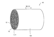
- FIG. 1 is a view of the heat conducting member 10 of the present invention as viewed from one end face in the axial direction
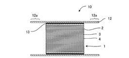
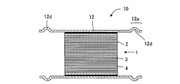
- FIG. 2 is a perspective view of the heat conducting member 10.
- the heat conducting member 10 includes a cylindrical ceramic body 11, a metal tube 12 on the outer peripheral side of the cylindrical ceramic body 11, and an intermediate member 13 sandwiched between the cylindrical ceramic body 11 and the metal tube 12.
- the cylindrical ceramic body 11 has a flow path that penetrates from one end surface 2 to the other end surface 2 and through which a first fluid that is a heating body flows.
- the intermediate material 13 is made of a material having at least a part having a Young's modulus of 150 GPa or less.
- the heat conducting member 10 is Heat exchange between the first fluid and the second fluid can be performed. Since the heat conducting member 10 includes the metal tube 12 on the outer peripheral side of the cylindrical ceramic body 11, the first fluid and the second fluid are completely separated, and these fluids are not mixed. Moreover, since the heat conducting member 10 includes the metal tube 12, it can be easily processed according to the installation location and the installation method, and has a high degree of freedom. The heat conducting member 10 can protect the cylindrical ceramic body 11 with the metal tube 12 and is resistant to external impacts.
- the intermediate material 13 made of a material having a Young's modulus of 150 GPa or less for the heat conducting member 10
- the adhesion between the metal tube 12 and the cylindrical ceramic body 11 can be enhanced, and the heat conductivity can be improved.
- the intermediate material 13 is in contact with at least a part of the metal tube 12 and the cylindrical ceramic body 11 in order to improve the thermal conductivity of the heat conducting member 10.
- the intermediate material 13 has a thermal conductivity of 1 W / m ⁇ K or more.
- the heat conductivity of the intermediate material 13 is 1 W / m ⁇ K or more, the heat conductivity of the heat conductive member 10 can be improved.
- Examples of the intermediate material 13 include a graphite sheet, a metal sheet, a gel sheet, and an elastoplastic fluid.
- Examples of the metal constituting the metal sheet include gold (Au), silver (Ag), copper (Cu), and aluminum (Al).
- An elasto-plastic fluid is a material that, if it is a small force, behaves as a solid without plastic deformation (has an elastic modulus), and deforms freely like a fluid when a large force is applied. Etc. are mentioned as examples. In view of adhesion, thermal conductivity, etc., it is preferable to use a graphite sheet as the intermediate material 13. Hereinafter, a graphite sheet will be described as an example of the intermediate material 13.
- the metal tube 12 and the cylindrical ceramic body 11 can be fitted by, for example, shrink fitting in a state where the intermediate material 13 made of a graphite sheet is sandwiched (first integrated method described later).
- the first fluid and the second fluid can be prevented from being mixed.
- sandwiching and interposing the intermediate material 13 made of a graphite sheet pressure is applied to the graphite sheet in an environment of normal temperature to 150 ° C. when the joint between the metal tube 12 and the cylindrical ceramic body 11 is used. Can be transmitted.
- the graphite sheet in the present specification is a sheet obtained by rolling a graphite mainly composed of expanded graphite into a sheet, or a sheet obtained by pyrolyzing a polymer film. Including what is called.
- the graphite sheet preferably has a Young's modulus in the thickness direction of 1 GPa or less and a thermal conductivity in the thickness direction of 1 W / m ⁇ K or more.
- the thermal conductivity in the thickness direction is more preferably 3 to 10 W / m ⁇ K.
- the thermal conductivity in the in-plane direction is preferably 5 to 1600 W / m ⁇ K, more preferably 100 to 400 W / m ⁇ K.
- the Young's modulus of the graphite sheet is preferably 1 MPa to 1 GPa. More preferably, it is 5 MPa to 500 MPa, and further preferably 10 MPa to 200 MPa. If the Young's modulus is 1 MPa or more, the density of graphite is sufficient and the thermal conductivity is good. On the other hand, when the pressure is 500 MPa or less, even a thin graphite sheet is sufficiently elastically deformed at the time of shrink fitting, and adhesion and stress relaxation effect of the metal tube 12 can be obtained.
- the thickness of the graphite sheet is preferably 25 ⁇ m to 1 mm, more preferably 25 ⁇ m to 500 ⁇ m, and even more preferably 50 ⁇ m to 250 ⁇ m.
- Graphite sheets become more expensive as they become thinner. Moreover, when it becomes thick, heat resistance will be produced. By using the graphite sheet in this range, the thermal conductivity is improved, and the heat in the cylindrical ceramic body 11 can be efficiently discharged to the outside of the metal tube 12.
- the cylindrical ceramic body 11 preferably has a thermal conductivity of 100 W / m ⁇ K or more. More preferably, it is 120 to 300 W / m ⁇ K, and still more preferably 150 to 300 W / m ⁇ K. By setting it as this range, heat conductivity becomes favorable and the heat
- FIG. 1 A thermal conductivity of 100 W / m ⁇ K or more. More preferably, it is 120 to 300 W / m ⁇ K, and still more preferably 150 to 300 W / m ⁇ K.
- the cylindrical ceramic body 11 is formed of ceramics in a cylindrical shape and has a fluid flow path that penetrates from one end surface 2 to the other end surface 2 in the axial direction.
- the cylindrical shape is not limited to a cylindrical shape (columnar shape), but is a prismatic shape having an elliptical cross section perpendicular to the axial (longitudinal) direction, an oval shape in which arcs are combined, a square shape, or other polygonal shapes. Also good.
- the cylindrical ceramic body 11 is preferably a honeycomb structure 1 having a partition wall 4 made of a porous body, and a plurality of cells serving as fluid flow paths defined by the partition wall 4.
- FIG. 1 and 2 show an embodiment in which a honeycomb structure 1 in which a large number of cells are formed is used as a cylindrical ceramic body 11.
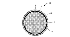
- FIG. 3 shows an embodiment in which a ceramic tube having no partition wall 4 and only an outer peripheral wall 7 and having a hollow interior is used as the cylindrical ceramic body 11.
- the cylindrical ceramic body 11 is preferably made of ceramics having excellent heat resistance, and considering heat conductivity in particular, it is preferable that SiC (silicon carbide) having high thermal conductivity is the main component.
- the main component means that 50% by mass or more of the cylindrical ceramic body 11 is silicon carbide.
- the entire cylindrical ceramic body 11 does not necessarily need to be composed of SiC (silicon carbide), and SiC (silicon carbide) may be included in the main body. That is, the cylindrical ceramic body 11 is preferably made of a ceramic containing SiC (silicon carbide).
- Si-impregnated SiC, (Si + Al) -impregnated SiC, metal composite SiC, Si 3 N 4 , SiC, or the like can be adopted, but a dense structure for obtaining a high heat exchange rate is adopted. Therefore, Si-impregnated SiC or (Si + Al) -impregnated SiC can be employed.
- Si-impregnated SiC has a structure in which the SiC particle surface is surrounded by solidified metal-silicon melt and SiC is integrally bonded via metal silicon, so that silicon carbide is shielded from an oxygen-containing atmosphere and prevented from oxidation. Is done.
- SiC has the characteristics of high thermal conductivity and easy heat dissipation, but SiC impregnated with Si is densely formed while exhibiting high thermal conductivity and heat resistance, and has sufficient strength as a heat transfer member.
- the cylindrical ceramic body 11 made of a Si—SiC-based (Si-impregnated SiC, (Si + Al) -impregnated SiC) material has excellent heat resistance, thermal shock resistance, oxidation resistance, and corrosion resistance against acids and alkalis. In addition to showing properties, it exhibits high thermal conductivity.
- the cell shape may be a circle, an ellipse, a triangle, a quadrangle, a hexagon, A desired shape may be appropriately selected from polygons and the like.
- the cell density of the honeycomb structure 1 (that is, the number of cells per unit cross-sectional area) is not particularly limited and may be appropriately designed according to the purpose, but is 25 to 2000 cells / in 2 (4 to 320 cells / cm 2 ) is preferable. When the cell density is larger than 25 cells / in 2, the strength of the partition walls 4 and the strength of the honeycomb structure 1 itself and the effective GSA (geometric surface area) can be made sufficient. On the other hand, when the cell density is 2000 cells / square inch or less, the pressure loss when the heat medium flows can be reduced.
- the number of cells per honeycomb structure 1 is preferably 1 to 10,000, and particularly preferably 200 to 2,000. If the number of cells is too large, the honeycomb itself becomes large, so the heat conduction distance from the first fluid side to the second fluid side becomes long, the heat conduction loss becomes large, and the heat flux becomes small. In addition, when the number of cells is small, the heat transfer area on the first fluid side becomes small, the heat resistance on the first fluid side cannot be lowered, and the heat flux becomes small.
- the thickness (wall thickness) of the partition walls 4 of the cells 3 of the honeycomb structure 1 may be appropriately designed according to the purpose, and is not particularly limited.
- the wall thickness is preferably 50 ⁇ m to 2 mm, and more preferably 60 ⁇ m to 500 ⁇ m.
- the wall thickness is 50 ⁇ m or more, the mechanical strength is improved and damage due to impact or thermal stress can be prevented.
- the thickness is 2 mm or less, the ratio of the cell volume to the honeycomb structure side is increased, so that the pressure loss of the fluid is reduced and the heat exchange rate can be improved.
- the density of the partition walls 4 of the cells 3 of the honeycomb structure 1 is preferably 0.5 to 5 g / cm 3 .
- the strength of the partition wall 4 is sufficient, and the partition wall 4 can be prevented from being damaged by pressure when the first fluid passes through the flow path.
- the honeycomb structure 1 itself does not become too heavy, and the weight can be reduced.
- a catalyst is formed on the wall surface inside the cell 3 of the honeycomb structure 1 through which the first fluid (high temperature side) passes. Is preferably carried. This is because in addition to the role of exhaust gas purification, reaction heat (exothermic reaction) generated during exhaust gas purification can also be exchanged.
- Noble metals platinum, rhodium, palladium, ruthenium, indium, silver, and gold
- the supported amount of the catalyst (catalyst metal + supported body) supported on the partition walls 4 of the cells 3 of the first fluid circulation part 5 of the honeycomb structure 1 through which the first fluid (high temperature side) passes is 10 to 400 g / L is preferable, and in the case of a noble metal, 0.1 to 5 g / L is more preferable.
- the amount of the catalyst (catalyst metal + support) supported is 10 g / L or more, the catalytic action is sufficiently exhibited.
- it is 400 g / L or less, the pressure loss does not become too large, and an increase in manufacturing cost can be suppressed.
- the metal tube 12 one having heat resistance and corrosion resistance is preferable.
- a SUS tube, a copper tube, a brass tube, or the like can be used.
- the temperature of the cooling water, which is the second fluid flowing on the outer peripheral surface 12h of the metal tube 12 can rise to around 120 ° C., but at this time, due to the difference in thermal expansion coefficient, the cylindrical ceramic body 11 and the metal tube 12 It is preferable to set the diameter of the metal tube 12 within the range of the following formula so that the pressure between the two does not escape. That is, the outer diameter of the cylindrical ceramic body 11 at room temperature of 25 ° C.
- the temperature is 1000 ° C.
- the inner diameter D of the metal tube 12 is d + 2 ⁇ c ⁇ 975 ⁇ ⁇ ⁇ d ⁇ D ⁇ d + 2 ⁇ c-125 ⁇ ( ⁇ ) ⁇ d It is preferable to set so that.
- the inner diameter D of the metal tube 12 is within a range where the pressure of the interference fit is surely applied in a temperature range from room temperature to 150 ° C. assumed at the joint between the cylindrical ceramic body 11 and the metal tube 12.
- the inner diameter D of the metal tube 12 is set within this range, it is possible to prevent a tensile stress from remaining in the metal tube 12 more than necessary.
- the outer diameter of the cylindrical ceramic body 11 is 42 mm
- the thermal expansion coefficient ⁇ of the cylindrical ceramic body 11 is 4.0 ⁇ 10 ⁇ 6
- the thermal expansion coefficient ⁇ of the metal tube 12 is 17 ⁇ 10 ⁇ . 6.
- the thickness c of the graphite sheet is 0.2 mm, 41.704 mm ⁇ D ⁇ 42.332 mm.
- SiC powders having different average particle diameters are mixed to prepare a mixture of SiC powders.
- This SiC powder mixture is mixed with a binder and water, and kneaded using a kneader to obtain a kneaded product.
- This kneaded product is put into a vacuum kneader to produce a cylindrical clay.
- the clay is extruded to form a honeycomb formed body.
- the shape and thickness of the outer peripheral wall, the thickness of the partition walls, the shape of the cells, the cell density, and the like can be made desired by selecting an appropriate form of die and jig. It is preferable to use a die made of a cemented carbide that hardly wears.
- the honeycomb formed body is formed so that the outer peripheral wall has a cylindrical shape or a quadrangular prism shape, and the inside of the outer peripheral wall is divided into a square lattice shape by partition walls. Further, these partition walls are formed so as to be parallel to each other at equal intervals in each of the directions orthogonal to each other and straight across the inside of the outer peripheral wall. Thereby, the cross-sectional shape of the cell other than the outermost peripheral portion inside the outer peripheral wall can be made square.
- the honeycomb formed body obtained by extrusion molding is dried.
- the honeycomb formed body is dried by an electromagnetic heating method, and then dried by an external heating method.
- moisture corresponding to 97% or more of the total amount of water contained in the honeycomb formed body before drying is removed from the honeycomb formed body.
- the honeycomb formed body is degreased in a nitrogen atmosphere. Furthermore, a lump of metal Si is placed on the honeycomb structure obtained by such degreasing and fired in a vacuum or in an inert gas under reduced pressure. During this firing, the mass of metal Si placed on the honeycomb structure is melted, and the outer peripheral wall 7 and the partition walls 4 are impregnated with metal Si.
- the thermal conductivity of the outer peripheral wall 7 and the partition wall 4 is set to 100 W / m ⁇ K
- a mass of 70 parts by mass of metal Si is used with respect to 100 parts by mass of the honeycomb structure.
- the thermal conductivity of the outer peripheral wall 7 and the partition walls 4 is set to 150 W / m ⁇ K
- 80 parts by mass of metal Si is used with respect to 100 parts by mass of the honeycomb structure.
- a method for integrating the honeycomb structure 1, the intermediate material 13, and the metal tube 12 manufactured as described above will be described.
- a graphite sheet used as the intermediate member 13 is wound around the outer peripheral surface 7 h of the outer peripheral wall 7 of the honeycomb structure 1.
- an adhesive By using an adhesive, a graphite sheet can be uniformly attached. It is desirable that the adhesive is sufficiently thin and has good heat conductivity.
- an interference-fitted state is obtained, so that the adhesion may be a full adhesion or a partial adhesion.
- the metal tube 12 is heated to about 1000 ° C. with a high-frequency heater.
- the honeycomb structure can be inserted into the metal tube 12 and integrated by shrink fitting to form the heat conducting member 10.
- the metal tube 12 is formed using a metal plate (flat plate).
- a graphite sheet is wound around the outer peripheral surface 7 h of the outer peripheral wall 7 of the honeycomb structure 1.
- the honeycomb structure 1 is wound and tightened while applying a metal plate (flat plate) to the honeycomb structure 1 (see FIG. 4).
- the end portions 12 a of the metal plate wound around the honeycomb structure 1 and formed into a cylindrical shape are joined to form a metal tube 12.
- laser welding can be used as the joining between the end portions 12a of the metal plates.
- the third method is a hot plastic working method.
- a graphite sheet is wound around the outer peripheral surface 7 h of the outer peripheral wall 7 of the honeycomb structure 1.
- the honeycomb structure 1 is installed inside the metal tube 12.
- the inner diameter of the metal tube 12 is sufficiently larger than the outer diameter of the honeycomb structure 1.
- the region where the honeycomb structure 1 of the metal tube 12 is installed is heated to about 400 to 1100 ° C. using a high-frequency heating device or the like.
- the metal tube 12 is reduced in diameter by pulling both ends of the metal tube while locally heating the metal tube 12.
- the heat conducting member 10 can be formed by cooling after the metal tube 12 and the honeycomb structure 1 are integrated.
- the heat conductive member 10 of the present invention is provided with an intermediate material 13 made of a graphite sheet or the like having a low Young's modulus between the cylindrical ceramic body 11 and the metal tube 12 on the outer periphery thereof, thereby improving adhesion.
- the thermal conductivity in the thickness direction (the radial direction of the tube) can be 3 W / m ⁇ K or more, and the thermal conductivity is good.
- the thermal conductivity in the longitudinal (axial) direction can be 250 W / m ⁇ K or more, and the thermal conductivity is also good. Since a side slip is possible with a graphite sheet or the like, stress due to a difference in thermal expansion between the cylindrical ceramic body 11 and the metal tube 12 hardly occurs. For this reason, thermal durability is sufficient practically.
- FIG. 5 is a cross-sectional view taken along a plane parallel to the axial direction showing another embodiment of the heat conducting member 10 of the present invention.
- the metal tube 12 is longer than the axial length of the honeycomb structure 1. If comprised in this way, it will be easy to process the edge part 12a of the metal pipe 12 according to the installation place and application of the heat conductive member 10.
- FIG. 6A shows a cross-sectional view taken along a plane parallel to the axial direction of the embodiment in which the intermediate member 13 is sandwiched only in part.
- 6B shows a cross-sectional view taken along a plane perpendicular to the axial direction of another embodiment in which the intermediate member 13 is sandwiched only in part.
- the intermediate material 13 does not necessarily have to be provided in the entire honeycomb structure 1. Even in such an embodiment, effects of thermal stress relaxation and improvement of heat conduction efficiency can be obtained. Further, the intermediate material 13 may be a net-like material.
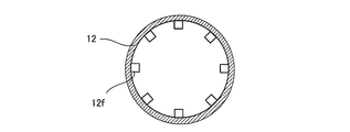
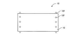
- FIG. 7A shows an embodiment in which fins 12 f are provided inside the metal tube 12.
- FIG. 7B is a cross-sectional view of the embodiment of FIG. 7A cut along a plane perpendicular to the axial direction. Fins 12 f are provided on the inner end 12 a of the metal tube 12. Thus, by providing the fin 12f on the metal tube 12, the rigidity of the metal tube can be increased.
- FIG. 8A shows an embodiment in which fins 12 f are provided on the outside of the metal tube 12.
- 8B is a cross-sectional view of the embodiment of FIG. 8A cut along a plane perpendicular to the axial direction. Fins 12f are provided over substantially the entire length in the axial direction outside the metal tube 12. Thus, by providing the fin 12f on the metal tube 12, the rigidity of the metal tube can be increased.
- FIG. 9A is a schematic view showing another embodiment in which fins 12 f are provided on the outside of the metal tube 12.
- FIG. 9B is a cross-sectional view of the embodiment of FIG. 9A cut along a plane perpendicular to the axial direction.
- the shape of the fin 12f is not limited to the embodiment of FIG. 8B or FIG. 9B.
- FIG. 10A is a cross-sectional view taken along a plane parallel to the axial direction showing an embodiment in which a step 12d is provided in the metal tube 12.
- FIG. 10B is a cross-sectional view taken along a plane perpendicular to the axial direction showing the embodiment of FIG. 10A.
- the step portion 12d is formed in a shape recessed inward. Such a portion can be formed by a press manufacturing method. By providing the recessed portion, the rigidity of the metal tube 12 can be increased. As shown in FIG. 11, a portion protruding outward may be formed on the metal tube 12 as the stepped portion 12d.
- FIG. 12A shows an embodiment in which a step 12d of the metal tube 12 is formed in a cylindrical shape from the vicinity of the end face 2 of the honeycomb structure 1 to the end 12a.
- the step portion 12d of the present embodiment has a reduced diameter from the vicinity of the end face 2 of the honeycomb structure 1 to the end portion 12a of the metal tube 12, and the step portion 12d is formed in a cylindrical shape (cylindrical shape). By forming such a step portion 12d, the stress of the metal tube 12 can be relaxed.
- Fig. 12B shows an embodiment in which a step 12d is formed in a circumferential shape on the metal tube 12 in the vicinity of the end face 2 of the honeycomb structure 1. By forming such a step portion 12d, the stress of the metal tube 12 can be relaxed.
- FIG. 12C shows an embodiment in which a step 12d protrudes outward from the end 12a of the metal tube 12 and is formed in a circumferential shape. By forming such a step portion 12d, the stress of the metal tube 12 can be relaxed.
- FIG. 13A shows an embodiment in which the axial edge of the outer peripheral wall 7 of the honeycomb structure 1 is chamfered.
- the shape of the edge include a C shape (C shape portion 7c) and an R shape (R shape portion 7r).
- the inner diameter of the metal tube 12 in the portion covering the edge of the outer peripheral wall 7 of the honeycomb structure 1 is 1.01 times or more than the inner diameter of the other portion.
- FIG. 14 shows a perspective view of the heat exchanger 30 including the heat conducting member 10 of the present invention.
- the heat exchanger 30 is formed by a heat conducting member 10 (honeycomb structure 1 + intermediate material 13 + metal tube 12) and a casing 21 that includes the heat conducting member 10 inside.
- the cells 3 of the honeycomb structure 1 of the cylindrical ceramic body 11 serve as the first fluid circulation part 5 through which the first fluid flows.
- the heat exchanger 30 is configured such that a first fluid having a temperature higher than that of the second fluid flows in the cells 3 of the honeycomb structure 1.
- an inlet 22 and an outlet 23 for the second fluid are formed in the casing 21, and the second fluid circulates on the outer peripheral surface 12 h of the metal tube 12 of the heat conducting member 10.
- the second fluid circulation portion 6 is formed by the inner surface 24 of the casing 21 and the outer peripheral surface 12 h of the metal tube 12.
- the second fluid circulation part 6 is a second fluid circulation part formed by the casing 21 and the outer peripheral surface 12h of the metal tube 12, and includes the first fluid circulation part 5, the partition wall 4 of the honeycomb structure 1, and the intermediate material. 13, which is separated by the metal pipe 12 and can conduct heat, receives heat of the first fluid flowing through the first fluid circulation portion 5 through the partition wall 4, the intermediate material 13, and the metal pipe 12, and circulates the first fluid. Heat is transferred to the heated object which is the second fluid. The first fluid and the second fluid are completely separated, and these fluids are configured not to mix.
- the first fluid circulation portion 5 is formed as a honeycomb structure, and in the case of the honeycomb structure, when the fluid passes through the cell 3, the fluid cannot flow into another cell 3 by the partition wall 4, and the honeycomb structure The fluid travels linearly from one inlet to the outlet. Moreover, the honeycomb structure 1 in the heat exchanger 30 of the present invention is not plugged, so that the heat transfer area of the fluid is increased and the size of the heat exchanger 30 can be reduced. Thereby, the amount of heat transfer per unit volume of the heat exchanger 30 can be increased. Furthermore, since it is not necessary to process the honeycomb structure 1 such as forming plugged portions or forming slits, the heat exchanger 30 can reduce the manufacturing cost.
- the heat exchanger 30 circulates the first fluid having a temperature higher than that of the second fluid and conducts heat from the first fluid to the second fluid.
- gas is circulated as the first fluid and liquid is circulated as the second fluid, heat exchange between the first fluid and the second fluid can be performed efficiently. That is, the heat exchanger 30 of the present invention can be applied as a gas / liquid heat exchanger.
- the heating element that is the first fluid to be circulated in the heat exchanger 30 of the present invention having the above configuration is not particularly limited as long as it is a medium having heat.
- the medium to be heated which is the second fluid that takes heat from the heating body (exchanges heat)
- Example 1 (Creation of clay) First, 70% by mass of SiC powder having an average particle size of 45 ⁇ m, 10% by weight of SiC powder having an average particle size of 35 ⁇ m, and 20% by weight of SiC powder having an average particle size of 5 ⁇ m were mixed to prepare a mixture of SiC powders. . 100 parts by mass of this SiC powder mixture was mixed with 4 parts by mass of binder and water, and kneaded using a kneader to obtain a kneaded product. This kneaded material was put into a vacuum kneader to produce a columnar clay.
- honeycomb formed body Next, the kneaded material was extruded to form a honeycomb formed body.
- the base was made of a hard metal that does not easily wear.
- the honeycomb molded body was formed such that the outer peripheral wall was formed into a cylindrical shape or a hollow quadrangular prism shape, and the inside of the outer peripheral wall was divided into a square lattice shape by partition walls. Further, these partition walls were formed so as to be parallel to each other at equal intervals in the directions orthogonal to each other and to traverse the inside of the outer peripheral wall straight. Thereby, the cross-sectional shape of the cell other than the outermost peripheral portion inside the outer peripheral wall was made square.
- the honeycomb formed body obtained by extrusion molding was dried.
- the honeycomb formed body was dried by an electromagnetic heating method, and subsequently dried by an external heating method.
- moisture corresponding to 97% or more of the total moisture contained in the honeycomb formed body before drying was removed from the honeycomb formed body.
- the honeycomb formed body was degreased at 500 ° C. for 5 hours in a nitrogen atmosphere. Furthermore, a lump of metal Si was placed on the honeycomb structure obtained by such degreasing and fired at 1450 ° C. for 4 hours in an inert gas under vacuum or reduced pressure. During the firing, the lump of metal Si placed on the honeycomb structure was melted, and the outer peripheral wall and partition walls were impregnated with metal Si.
- the thermal conductivity of the outer peripheral wall and partition walls was set to 150 W / m ⁇ K, 80 parts by mass of metal Si mass was used with respect to 100 parts by mass of the honeycomb structure.
- a cylindrical (tubular) honeycomb structure 1 having a material of silicon carbide, a main body size of a diameter (outer diameter) of 40 mm, and a length of 80 mm was manufactured. That is, the honeycomb structure 1 was used as the cylindrical ceramic body 11.
- the honeycomb structure 1 had a cell density of 23.3 cells / cm 2
- the partition walls 4 had a thickness (wall thickness) of 0.3 mm
- the honeycomb structure 1 had a thermal conductivity of 150 kW / m ⁇ K.
- a graphite sheet with an acrylic adhesive (Otsuka Electric HT-705A) was attached to the outer peripheral surface 7h of the honeycomb structure 1.
- a graphite sheet having a thermal conductivity of 6 W / m ⁇ K in the thickness direction and a Young's modulus of 0.1 GPa was used. This time, a graphite sheet with an adhesive was used, but it may be bonded using a separate heat conductive adhesive.
- the metal tube 12 was heated to 1000 ° C. with a high-frequency heater, and the honeycomb structure 1 was inserted into the metal tube 12 and shrink-fitted.
- the metal tube 12 has the following diameter so that the pressure does not escape during use. That is, the outer diameter of the cylindrical ceramic body 11 (honeycomb structure 1) at room temperature 25 ° C is d, the thickness of the graphite sheet is c, the thermal expansion coefficient of the cylindrical ceramic body 11 is ⁇ , and the thermal expansion coefficient of the metal tube 12 Where ⁇ is the inner diameter D of the metal tube, d + 2 ⁇ c ⁇ 975 ⁇ ⁇ ⁇ d ⁇ D ⁇ d + 2 ⁇ c-125 ⁇ ( ⁇ ) ⁇ d What was used.
- the outer diameter of the cylindrical ceramic body 11 is 42 mm
- the thermal expansion coefficient ⁇ of the cylindrical ceramic body 11 is 4 ⁇ 10 ⁇ 6 / ° C.
- the thermal expansion coefficient ⁇ of the metal tube 12 is 17 ⁇ 10 ⁇ 6 /
- the thickness c of the graphite sheet was 0.2 mm, and 41.704 mm ⁇ D ⁇ 42.332 mm.
- the metal tube 12 is a SUS304 thin wall tube.
- Comparison target As a comparison target (reference sample), a single cylindrical ceramic body 11 (honeycomb structure 1) that was not covered with the metal tube 12 was prepared.
- the cylindrical ceramic body 11 is the same as that of the first embodiment.
- the (cooling) water of the second fluid was flowed at a flow rate of 10 L / min with respect to the honeycomb structure 1.
- the second fluid passage is provided on the outer peripheral side of the heat conducting member 10 serving as the first fluid passage (see FIG. 14).
- Table 1 shows the heat transfer efficiency.
- the heat conduction member without the graphite sheet (Comparative Example 1) has a heat transfer efficiency reduced by 5.0%, but by sandwiching the graphite sheet (Example 1) ) Was reduced to 2.6%. Thereby, it can be said that the improvement in thermal adhesion was confirmed by the graphite sheet. That is, when the cylindrical ceramic body 11 is covered with a metal tube, the thermal bonding state can be improved by sandwiching the graphite sheet.
- Example 1 Reference Example, Comparative Examples 1 and 2
- Example 1 Reference Example, Comparative Examples 1 and 2
- the same heat transfer efficiency test was performed on other intermediate materials 13 to obtain the heat transfer efficiency. Further, after the heat transfer efficiency test, it was examined whether or not the cylindrical ceramic body 11 had cracks. It shows in Table 2.
- Example 1, Reference Example, and Comparative Example 1 in Table 2 are the same as in Table 1. Except for the reference example and the comparative example 1, the cylindrical ceramic body 11 + the intermediate material 13 + the metal tube 12 are used. The reference example is the cylindrical ceramic body 11 alone, and the comparative example 1 is the cylindrical ceramic body 11 + metal tube 12 without the intermediate material 13.
- the heat exchanger of the present invention is not particularly limited even in the automotive field and the industrial field as long as it is used for heat exchange between a heating body (high temperature side) and a heated body (low temperature side).
- it is suitable when at least one of the heated body or the heated body is a liquid.
Abstract
筒状セラミックス体を金属管で被覆する場合において、熱的な結合状態を保ちつつ、熱膨張差による応力の発生を抑制する熱伝導部材を提供する。熱伝導部材10は、筒状セラミックス体11と、筒状セラミックス体11の外周側に金属管12と、筒状セラミックス体11と金属管12との間に挟み込まれた中間材13と、を備える。筒状セラミックス体11は、一方の端面から他方の端面まで貫通し、加熱体である第一の流体が流通する流路を有する。中間材13は、少なくとも一部がヤング率150GPa以下である材質からなる。そして、筒状セラミックス体11の内部に第一の流体を、金属管12の外周面12h側に第一の流体よりも低温の第二の流体を流通させることにより、第一の流体と第二の流体との熱交換を行うことができる。
Description
本発明は、筒状セラミックス体を金属管で被覆した熱伝導部材に関する。
高温の流体から低温の流体へ熱交換することにより、熱を有効利用することができる。例えば、エンジンなどの燃焼排ガスなどの高温気体からの熱を回収する熱回収技術がある。気体/液体熱交換器としては、自動車のラジエター、空調室外機などのフィン付チューブ型熱交換器が一般的である。しかしながら、例えば自動車排ガスのような気体から熱を回収するには、一般的な金属製熱交換器では耐熱性に乏しく、高温での使用が困難である。そこで、耐熱性、耐熱衝撃、耐腐食などを有する耐熱金属やセラミックス材料などが適している。しかし耐熱金属は、価格が高い上に加工が難しい、密度が高く重い、熱伝導が低いなどの課題がある。
そこで、セラミックス材料を用いた熱回収技術が開発されている。例えば、筒状セラミックス体を用いて熱交換を行う技術がある。この場合、筒状セラミックス体の内部に第一の流体を流通させ、外部に第二の流体を流通させることにより、熱交換を行う。気体と液体とで筒状セラミックス体を用いて熱交換する場合、筒状セラミックス体が液体漏れを起こし2つの流体が混ざり合うことがないように、筒状セラミックス体をシールドする必要がある。
特許文献1には、筒状セラミックス体であるセラミックス製のハニカム構造体と金属基材(金属管)を一体化させることで熱を回収する技術が開示されている。
しかしながら、特許文献1のように、セラミックス製のハニカム構造体と金属基材(金属管)とを一体化させた場合、使用時に熱膨張が発生し、ハニカム構造体と金属基材(金属管)との密着性が悪化したり、熱応力が発生し、ハニカム構造体が損傷したりする問題がある。
また、圧入により、筒状セラミックス体と金属管とを一体化させた場合、密着不足によって熱抵抗が大きくなったり、過剰な予圧による熱伝導部材の破壊が起こったり、さらには金属管に大きな残留応力が残ることで耐久性が低下する。
ロウ付けにより、筒状セラミックス体と金属管とを一体化させた場合、濡れ性の確保が難しく、熱膨張差により応力が発生する。
本発明の課題は、筒状セラミックス体を金属管で被覆する場合において、熱的な結合状態を保ちつつ、熱膨張差による応力の発生を抑制する熱伝導部材を提供することである。
本発明者らは、筒状セラミックスとその外周側の金属管との間にヤング率150GPa以下である材質からなる中間材を備えることにより、上記課題を解決できることを見出した。すなわち、本発明によれば、以下の熱伝導部材が提供される。
[1] 一方の端面から他方の端面まで貫通し、加熱体である第一の流体が流通する流路を有する筒状セラミックス体と、前記筒状セラミックス体の外周側に金属管と、前記筒状セラミックス体と前記金属管との間に挟み込まれた少なくとも一部がヤング率150GPa以下である材質からなる中間材と、を備え、前記筒状セラミックス体の内部に前記第一の流体を、前記金属管の外周面側に前記第一の流体よりも低温の第二の流体を流通させ、前記第一の流体と前記第二の流体との熱交換を行う熱伝導部材。
[2] 前記中間材が、前記金属管と前記筒状セラミックス体との少なくとも一部に接触している前記[1]に記載の熱伝導部材。
[3] 前記中間材は、少なくとも一部の熱伝導率が1W/m・K以上である前記[1]または[2]に記載の熱伝導部材。
[4] 前記中間材は、グラファイトシートから成っており、ヤング率が1GPa以下、厚み方向の熱伝導率が3W/m・K以上である前記[1]~[3]のいずれかに記載の熱伝導部材。
[5] 前記筒状セラミックス体は、熱伝導率が100W/m・K以上である前記[1]~[4]のいずれかに記載の熱伝導部材。
[6] 前記筒状セラミックス体は、多孔質体からなる隔壁を有し、前記隔壁によって、流体の流路となる多数のセルが区画形成されたハニカム構造体である前記[1]~[5]のいずれかに記載の熱伝導部材。
[7] 前記ハニカム構造体は、主成分が炭化珪素である前記[6]に記載の熱伝導部材。
筒状セラミックス体とその外周側の金属管との間にヤング率150GPa以下である材質からなる中間材を備えることにより、密着性が向上する。このため熱伝導性が良好となり、効率的に筒状セラミックス体内の熱を金属管の外側に排出できる。また、軸(長手)方向の熱伝導性が極めて良いため、先端(入口)側の熱を後(出口)側に逃がすことができる。中間材としてグラファイトシートを用いた場合、グラファイトシートにより、横滑りが可能なため、筒状セラミックス体と金属管と間の熱膨張差による応力が発生しにくい。金属管と筒状セラミックス体との接合部は最大で150℃程度の温度に曝される恐れがあるが、グラファイトの耐熱温度は400℃以上であり十分である。また、腐食の影響の心配がない。
以下、図面を参照しつつ本発明の実施の形態について説明する。本発明は、以下の実施形態に限定されるものではなく、発明の範囲を逸脱しない限りにおいて、変更、修正、改良を加え得るものである。
図1に、本発明の熱伝導部材10を軸方向の一方の端面から見た図、図2に、熱伝導部材10の斜視図を示す。熱伝導部材10は、筒状セラミックス体11と、筒状セラミックス体11の外周側に金属管12と、筒状セラミックス体11と金属管12との間に挟み込まれた中間材13と、を備える。筒状セラミックス体11は、一方の端面2から他方の端面2まで貫通し、加熱体である第一の流体が流通する流路を有する。中間材13は、少なくとも一部がヤング率150GPa以下である材質からなる。そして、筒状セラミックス体11の内部に第一の流体を、金属管12の外周面12h側に第一の流体よりも低温の第二の流体を流通させることにより、熱伝導部材10は、第一の流体と第二の流体との熱交換を行うことができる。熱伝導部材10は、筒状セラミックス体11の外周側に金属管12を備えるため、第一の流体と第二の流体とは、完全に分離されており、これらの流体は混じり合わない。また、熱伝導部材10は、金属管12を備えるため、設置場所や設置方法により加工することが容易であり、自由度が高い。熱伝導部材10は、金属管12によって筒状セラミックス体11を保護することができ外部からの衝撃にも強い。
熱伝導部材10にヤング率150GPa以下である材質からなる中間材13を用いることにより、金属管12と筒状セラミックス体11との密着性を高めて、熱伝導性を向上させることができる。この場合、中間材13が、金属管12と筒状セラミックス体11との少なくとも一部に接触していることが、熱伝導部材10の熱伝導性を良好とするために好ましい。
さらに、中間材13は、少なくとも一部の熱伝導率が1W/m・K以上であることが好ましい。中間材13の熱伝導率が1W/m・K以上であることにより、熱伝導部材10の熱伝導性を向上させることができる。
中間材13としては、グラファイトシート、金属シート、ゲルシート、弾塑性流体等が挙げられる。金属シートを構成する金属としては、金(Au)、銀(Ag)、銅(Cu)、アルミニウム(Al)等が挙げられる。弾塑性流体とは、小さな力であれば、塑性変形せずに固体として振るまい(弾性率を有する)、大きな力を加えると自由に変形して流体のような変形をする材料であり、グリース等が例として挙げられる。中間材13として、密着性や熱伝導性等を考慮すると、グラファイトシートを用いることが好ましい。以下、中間材13として、グラファイトシートを例として説明する。
金属管12と筒状セラミックス体11とを、グラファイトシートからなる中間材13を挟んだ状態で、例えば、焼きばめにより嵌合させることができる(後述する一体化の第一の方法)。金属管12と筒状セラミックス体11とを一体化することにより、第一の流体と第二の流体とが混ざり合うことを防止することができる。グラファイトシートからなる中間材13を挟んで焼きばめすることにより、金属管12と筒状セラミックス体11との接合部の使用時の常温~150℃の環境において、グラファイトシートに圧がかかり、熱を伝達することができる。
本明細書におけるグラファイトシートとは、膨張黒鉛を主成分とするグラファイトを圧延しシート状に加工したものや、高分子フィルムを熱分解して得られるシート状のものであり、黒鉛シート、カーボンシートと称されるものも含む。グラファイトシートは、厚み方向のヤング率が1GPa以下、厚み方向の熱伝導率が1W/m・K以上であることが好ましい。厚み方向の熱伝導率について、より好ましくは、3~10W/m・Kである。また、面内方向の熱伝導率は、5~1600W/m・Kが好ましく、100~400W/m・Kがより好ましい。
また、グラファイトシートのヤング率は、1MPa~1GPaであることが好ましい。より好ましくは、5MPa~500MPa、さらに好ましくは、10MPa~200MPaである。ヤング率が1MPa以上であればグラファイトの密度が十分であり熱伝導性が良い。一方、500MPa以下である場合、薄いグラファイトシートでも焼きばめ時に十分弾性変形し、密着性や金属管12の応力緩和効果が得られる。
グラファイトシートの厚みは、25μm~1mmであることが好ましく、25μm~500μmであることがより好ましく、50μm~250μmであることがさらに好ましい。グラファイトシートは、薄くなるほど高価になる。また厚くなると、熱抵抗を生じる。この範囲のグラファイトシートを使用することにより、熱伝導性が良好となり、効率的に筒状セラミックス体11内の熱を金属管12の外側に排出できる。
筒状セラミックス体11は、熱伝導率が100W/m・K以上であることが好ましい。より好ましくは、120~300W/m・K、さらに好ましくは、150~300W/m・Kである。この範囲とすることにより、熱伝導性が良好となり、効率的に筒状セラミックス体11内の熱を金属管12の外側に排出できる。
なお、筒状セラミックス体11とは、セラミックスで筒状に形成され、軸方向の一方の端面2から他方の端面2まで貫通する流体の流路を有するものである。筒状とは、円筒状(円柱状)に限らず、軸(長手)方向に垂直な断面が楕円形状、円弧が複合されたオーバル形状、四角形、またはその他の多角形の、角柱状であってもよい。筒状セラミックス体11は、多孔質体からなる隔壁4を有し、隔壁4によって、流体の流路となる多数のセルが区画形成されたハニカム構造体1であることが好ましい。隔壁4を有することにより、筒状セラミックス体11の内部を流通する流体からの熱を効率よく集熱し、外部に伝達することができる。図1及び図2は、多数のセルが形成されたハニカム構造体1を筒状セラミックス体11として用いた実施形態を示す。また、図3には、隔壁4を有さず外周壁7のみで内部が中空のセラミックス管を筒状セラミックス体11として用いた実施形態を示す。
筒状セラミックス体11は、耐熱性に優れるセラミックスを用いることが好ましく、特に伝熱性を考慮すると、熱伝導性が高いSiC(炭化珪素)が主成分であることが好ましい。なお、主成分とは、筒状セラミックス体11の50質量%以上が炭化珪素であることを意味する。
但し、必ずしも筒状セラミックス体11の全体がSiC(炭化珪素)で構成されている必要はなく、SiC(炭化珪素)が本体中に含まれていれば良い。即ち、筒状セラミックス体11は、SiC(炭化珪素)を含むセラミックスからなるものであることが好ましい。
なお、SiC(炭化珪素)であっても多孔体の場合は高い熱伝導率が得られないため、筒状セラミックス体11の作製過程でシリコンを含浸させて緻密体構造とすることが好ましい。緻密体構造にすることで高い熱伝導率が得られる。例えば、SiC(炭化珪素)の多孔体の場合、20W/m・K程度であるが、緻密体とすることにより、150W/m・K程度とすることができる。
筒状セラミックス体11として、Si含浸SiC、(Si+Al)含浸SiC、金属複合SiC、Si3N4、及びSiC等を採用することができるが、高い熱交換率を得るための緻密体構造とするためにSi含浸SiC、(Si+Al)含浸SiCを採用することができる。Si含浸SiCは、SiC粒子表面を金属珪素融体の凝固物が取り囲むとともに、金属珪素を介してSiCが一体に接合した構造を有するため、炭化珪素が酸素を含む雰囲気から遮断され、酸化から防止される。さらに、SiCは、熱伝導率が高く、放熱しやすいという特徴を有するが、Siを含浸するSiCは、高い熱伝導率や耐熱性を示しつつ、緻密に形成され、伝熱部材として十分な強度を示す。つまり、Si-SiC系(Si含浸SiC、(Si+Al)含浸SiC)材料からなる筒状セラミックス体11は、耐熱性、耐熱衝撃性、耐酸化性をはじめ、酸やアルカリなどに対する耐蝕性に優れた特性を示すとともに、高熱伝導率を示す。
筒状セラミックス体11を、隔壁4によって流路となる複数のセル3が区画形成されたハニカム構造体1として形成する場合、セル形状は、円形、楕円形、三角形、四角形、六角形、その他の多角形等の中から所望の形状を適宜選択すればよい。
ハニカム構造体1のセル密度(即ち、単位断面積当たりのセルの数)については特に制限はなく、目的に応じて適宜設計すればよいが、25~2000セル/平方インチ(4~320セル/cm2)の範囲であることが好ましい。セル密度を25セル/平方インチより大きくすると、隔壁4の強度、ひいてはハニカム構造体1自体の強度及び有効GSA(幾何学的表面積)を十分なものとすることができる。一方、セル密度を2000セル/平方インチ以下とすると、熱媒体が流れる際の圧力損失を小さくすることができる。
また、ハニカム構造体1の1つ当たりのセル数は、1~10,000が望ましく、200~2,000が特に望ましい。セル数が多すぎるとハニカム自体が大きくなるため第一の流体側から第二の流体側までの熱伝導距離が長くなり、熱伝導ロスが大きくなり熱流束が小さくなる。またセル数が少ない時には第一の流体側の熱伝達面積が小さくなり第一の流体側の熱抵抗を下げることが出来ず熱流束が小さくなる。
ハニカム構造体1のセル3の隔壁4の厚さ(壁厚)についても、目的に応じて適宜設計すればよく、特に制限はない。壁厚を50μm~2mmとすることが好ましく、60μm~500μmとすることが更に好ましい。壁厚を50μm以上とすると、機械的強度が向上して衝撃や熱応力による破損を防止できる。一方、2mm以下とすると、ハニカム構造体側に占めるセル容積の割合が大きくなることにより流体の圧力損失が小さくなり、熱交換率を向上させることができる。
ハニカム構造体1のセル3の隔壁4の密度は、0.5~5g/cm3であることが好ましい。0.5g/cm3以上の場合、隔壁4の強度が十分であり、第一の流体が流路内を通り抜ける際に圧力により隔壁4が破損することを防止できる。また、5g/cm3以下であると、ハニカム構造体1自体が重くなりすぎず、軽量化することができる。上記の範囲の密度とすることにより、ハニカム構造体1を強固なものとすることができる。また、熱伝導率を向上させる効果も得られる。
熱交換器30(図14参照)に流通させる第一の流体(高温側)が排ガスの場合、第一の流体(高温側)が通過するハニカム構造体1のセル3内部の壁面には、触媒が担持されていることが好ましい。これは、排ガス浄化の役割に加えて、排ガス浄化の際に発生する反応熱(発熱反応)も熱交換することが可能になるためである。貴金属(白金、ロジウム、パラジウム、ルテニウム、インジウム、銀、及び金)、アルミニウム、ニッケル、ジルコニウム、チタン、セリウム、コバルト、マンガン、亜鉛、銅、亜鉛、スズ、鉄、ニオブ、マグネシウム、ランタン、サマリウム、ビスマス及びバリウムからなる群から選択された元素を少なくとも一種を含有すると良い。これらは金属、酸化物、及びそれ以外の化合物であっても良い。
第一の流体(高温側)が通過するハニカム構造体1の第一流体流通部5のセル3の隔壁4に担持される触媒(触媒金属+担持体)の担持量としては、10~400g/Lであることが好ましく、貴金属であれば0.1~5g/Lであることが更に好ましい。触媒(触媒金属+担持体)の担持量を10g/L以上とすると、触媒作用が十分に発現する。一方、400g/L以下とすると、圧力損失が大きくなりすぎず、製造コストの上昇も抑えることができる。
金属管12としては、耐熱性、耐蝕性のあるものが好ましく、例えば、SUS管、銅管、真鍮管等を用いることができる。金属管12の外周面12h上を流通する第二の流体である冷却水の水温は120℃前後まで上昇しうるが、この時に熱膨張率の差により、筒状セラミックス体11と金属管12との間の圧力が抜けてしまわないように、金属管12の径を下記の式の範囲にすることが好ましい。すなわち、室温25℃での筒状セラミックス体11の外径をd、グラファイトシートの厚みをc、筒状セラミックス体11の熱膨張係数をα、金属管12の熱膨張係数をβ、焼きばめ温度を1000℃とすると、金属管12の内径Dは、
d+2×c-975×β×d<D<d+2×c-125×(β-α)×d
となるように設定することが好ましい。
d+2×c-975×β×d<D<d+2×c-125×(β-α)×d
となるように設定することが好ましい。
上記の金属管12の内径Dは、筒状セラミックス体11と金属管12との接合部で想定される常温~150℃までの温度域で、締まりばめの圧力が確実にかかる範囲である。金属管12の内径Dをこの範囲とすることにより、必要以上に金属管12に引張応力が残らないようにすることができる。具体的には、例えば、筒状セラミックス体11の外径が42mm、筒状セラミックス体11の熱膨張係数αが4.0×10⁻⁶、金属管12の熱膨張係数βが17×10-6、グラファイトシートの厚みcが0.2mmである場合は、41.704mm<D<42.332mmである。
(熱伝導部材の製造方法)
次に、本発明の熱伝導部材10の製造方法を説明する。まず、平均粒径の異なるSiC粉末を混ぜ合わせて、SiC粉末の混合物を調製する。このSiC粉末の混合物に、バインダー、水を混ぜ合わせ、ニーダーを用いて混練することにより、混練物を得る。この混練物を真空土練機に投入し、円柱状の坏土を作製する。
次に、本発明の熱伝導部材10の製造方法を説明する。まず、平均粒径の異なるSiC粉末を混ぜ合わせて、SiC粉末の混合物を調製する。このSiC粉末の混合物に、バインダー、水を混ぜ合わせ、ニーダーを用いて混練することにより、混練物を得る。この混練物を真空土練機に投入し、円柱状の坏土を作製する。
次に、坏土を押出成形してハニカム成形体を形成する。押出成形では、適当な形態の口金や治具を選択することにより、外周壁の形状や厚さ、隔壁の厚さ、セルの形状、セル密度などを所望のものにすることができる。口金は、摩耗し難い超硬合金で作られたものを用いることが好ましい。ハニカム成形体については、外周壁を円筒形状または四角柱形状とし、外周壁の内部を隔壁により四角形の格子状に区分された構造となるように形成する。また、これらの隔壁については、互いに直交する方向のそれぞれで等間隔に並行し、かつ、真っすぐに外周壁の内部を横切るように形成する。これにより、外周壁の内部の最外周部以外にあるセルの断面形状を正方形にすることができる。
次に、押出成形により得たハニカム成形体の乾燥を行なう。まず、ハニカム成形体を電磁波加熱方式で乾燥し、続いて、外部加熱方式で乾燥を行なう。こうした二段階の乾燥により、乾燥前のハニカム成形体に含まれる全水分量の97%以上に相当する水分をハニカム成形体から除去する。
次に、ハニカム成形体に対して窒素雰囲気で脱脂を行なう。さらに、こうした脱脂により得られたハニカム構造体の上に金属Siの塊を載せ、真空中または減圧の不活性ガス中で、焼成をする。この焼成中に、ハニカム構造体の上に載せた金属Siの塊を融解させ、外周壁7や隔壁4に金属Siを含浸させる。例えば、外周壁7や隔壁4の熱伝導率を100W/m・Kにする場合には、ハニカム構造体100質量部に対して70質量部の金属Siの塊を使用する。また、外周壁7や隔壁4の熱伝導率を150W/m・Kにする場合には、ハニカム構造体100質量部に対して80質量部の金属Siの塊を使用する。
次に、上記のようにして製造したハニカム構造体1、中間材13、及び金属管12の一体化の方法について説明する。第一の方法は、まず、中間材13として用いるグラファイトシートをハニカム構造体1の外周壁7の外周面7hに巻き付ける。このとき、接着剤を用いて貼り付けてもよい。接着剤を用いることにより、一様にグラファイトシートを貼り付けることができる。接着剤は、十分に薄く良伝熱性であることが望ましい。また、焼きばめ後は締まりばめ状態となるため、接着は、全面接着でも部分接着でもよい。続いて金属管12を高周波加熱機で1000℃程度まで昇温させる。そして、ハニカム構造体を金属管12に挿入して焼きばめにより一体化し、熱伝導部材10を形成することができる。
ハニカム構造体1、中間材13、及び金属管12の一体化の第二の方法について説明する。第二の方法は、金属板(平板)を用いて金属管12とする。まず、ハニカム構造体1の外周壁7の外周面7hにグラファイトシートを巻き付ける。次に、ハニカム構造体1に金属板(平板)を圧をかけつつ、巻き付けて締め付ける(図4参照)。そしてハニカム構造体1に巻き付けられて円筒状になった金属板の端部12a同士を接合して金属管12とする。金属板の端部12a同士の接合としては、例えば、レーザー溶接を用いることができる。
ハニカム構造体1、中間材13、及び金属管12の一体化の第三の方法について説明する。第三の方法は、熱間塑性加工法である。まず、ハニカム構造体1の外周壁7の外周面7hにグラファイトシートを巻き付ける。次に、ハニカム構造体1を金属管12の内部に設置する。金属管12の内径はハニカム構造体1の外周径に比べ十分に大きいものを使用する。続いて、金属管12のハニカム構造体1が設置されている領域を、高周波加熱装置等を用いて400~1100℃程度まで昇温させる。金属管12を局所的に加熱しながら金属管両端部を引っ張ることで、金属管12が縮径する。金属管12とハニカム構造体1とが一体化した後に冷却することで、熱伝導部材10を形成することができる。
本発明の熱伝導部材10は、筒状セラミックス体11とその外周側の金属管12との間に、低ヤング率のグラファイトシート等からなる中間材13を備えることにより、密着性が向上する。このため厚み方向(管の径方向)の熱伝導率を3W/m・K以上とすることができ、熱伝導性が良好である。また、長手(軸)方向の熱伝導率を250W/m・K以上とすることができ、熱伝導性も良好である。グラファイトシート等により、横滑りが可能なため、筒状セラミックス体11と金属管12間の熱膨張差による応力が発生しにくい。このため、実用上熱耐久性が十分である。
図5は本発明の熱伝導部材10の他の実施形態を示す軸方向に平行な面で切断した断面図である。図5に示すように、金属管12は、ハニカム構造体1の軸方向の長さよりも長い。このように構成すると、熱伝導部材10の設置場所や用途に応じて、金属管12の端部12aを加工しやすい。
図6Aに一部にのみ中間材13が挟まれた実施形態の軸方向に平行な面で切断した断面図を示す。また、図6Bに一部にのみ中間材13が挟まれた別の実施形態の軸方向に垂直な面で切断した断面図を示す。中間材13は、図6A及び図6Bに示すように、必ずしもハニカム構造体1の全体に備えられていなくてもよい。このような実施形態においても、熱応力緩和や熱伝導効率の向上の効果が得られる。また、中間材13は、網目状のものであってもよい。
図7Aに、金属管12の内側にフィン12fを設けた実施形態を示す。また、図7Bは、図7Aの実施形態を軸方向に垂直な面で切断した断面図である。金属管12の内側の端部12aにフィン12fが設けられている。このように、金属管12にフィン12fを設けることにより、金属管の剛性を上げることができる。
また、図8Aに、金属管12の外側にフィン12fを設けた実施形態を示す。また、図8Bは、図8Aの実施形態を軸方向に垂直な面で切断した断面図である。金属管12の外側の軸方向のほぼ全長にわたってフィン12fが設けられている。このように、金属管12にフィン12fを設けることにより、金属管の剛性を上げることができる。
図9Aは、金属管12の外側にフィン12fを設けた他の実施形態を示す模式図である。また、図9Bは、図9Aの実施形態を軸方向に垂直な面で切断した断面図である。フィン12fの形状は、図8Bや図9Bの実施形態に限定されない。
図10Aは、金属管12に段部12dを設けた実施形態を示す軸方向に平行な面で切断した断面図である。また、図10Bは、図10Aの実施形態を示す軸方向に垂直な面で切断した断面図である。本実施形態では、段部12dは、内側に凹んだ形状に形成されている。このような形状の部位は、プレス製法により形成することができる。凹んだ部位を設けることで、金属管12の剛性を上げることができる。図11のように、段部12dとして、金属管12に外側に出っ張った部位を形成してもよい。
図12Aに金属管12の、ハニカム構造体1の端面2の近傍から端部12aまで段部12dが筒状に形成された実施形態を示す。本実施形態の段部12dは、ハニカム構造体1の端面2の近傍から金属管12の端部12aまで縮径とされており、段部12dが筒状(円筒状)に形成されている。このような段部12dを形成することにより、金属管12の応力を緩和することができる。
図12Bにハニカム構造体1の端面2の近傍の金属管12に段部12dが円周状に形成された実施形態を示す。このような段部12dを形成することにより、金属管12の応力を緩和することができる。
図12Cに金属管12の端部12aに段部12dが外側に出っ張って円周状に形成された実施形態を示す。このような段部12dを形成することにより、金属管12の応力を緩和することができる。
図13Aに、ハニカム構造体1の外周壁7の軸方向のエッジを面取りした実施形態を示す。エッジの形状としては、C形状(C形状部7c)またはR形状(R形状部7r)が挙げられる。このようにエッジを面取りした形状に形成することにより、ハニカム構造体1のエッジの欠けを防止することができる。
また、図13Bに示すように、ハニカム構造体1の外周壁7のエッジにかかる部分の金属管12の内径を他の部分の内径よりも1.01倍以上あるように構成することも好ましい。このように構成することにより、ハニカム構造体1の外周壁7のエッジの欠けを防止することができる。
図14に本発明の熱伝導部材10を含む熱交換器30の斜視図を示す。図14に示すように、熱交換器30は、熱伝導部材10(ハニカム構造体1+中間材13+金属管12)と、熱伝導部材10を内部に含むケーシング21とによって形成されている。筒状セラミックス体11のハニカム構造体1のセル3が第一の流体が流通する第一流体流通部5となる。熱交換器30は、ハニカム構造体1のセル3内を、第二の流体よりも高温の第一の流体が流通するように構成されている。また、ケーシング21に第二の流体の入口22及び出口23が形成されており、第二の流体は、熱伝導部材10の金属管12の外周面12h上を流通する。
つまり、ケーシング21の内側面24と金属管12の外周面12hとによって第二流体流通部6が形成されている。第二流体流通部6は、ケーシング21と金属管12の外周面12hとによって形成された第二の流体の流通部であり、第一流体流通部5とハニカム構造体1の隔壁4、中間材13、金属管12によって隔たれて熱伝導可能とされており、第一流体流通部5を流通する第一の流体の熱を隔壁4、中間材13、金属管12を介して受け取り、流通する第二の流体である被加熱体へ熱を伝達する。第一の流体と第二の流体とは、完全に分離されており、これらの流体は混じり合わないように構成されている。
第一流体流通部5は、ハニカム構造として形成されており、ハニカム構造の場合、流体がセル3の中を通り抜ける時には、流体は隔壁4により別のセル3に流れ込むことが出来ず、ハニカム構造体1の入口から出口へと直線的に流体が進む。また、本発明の熱交換器30内のハニカム構造体1は、目封止されておらず、流体の伝熱面積が増し熱交換器30のサイズを小さくすることができる。これにより、熱交換器30の単位体積あたりの伝熱量を大きくすることができる。さらに、ハニカム構造体1に目封止部の形成やスリットの形成等の加工を施すことが不要なため、熱交換器30は、製造コストを低減することができる。
熱交換器30は、第二の流体よりも高温である第一の流体を流通させ、第一の流体から第二の流体へ熱伝導するようにすることが好ましい。第一の流体として気体を流通させ、第二の流体として液体を流通させると、第一の流体と第二の流体の熱交換を効率よく行うことができる。つまり、本発明の熱交換器30は、気体/液体熱交換器として適用することができる。
以上のような構成の本発明の熱交換器30に流通させる第一の流体である加熱体としては、熱を有する媒体であれば、気体、液体等、特に限定されない。例えば、気体であれば自動車の排ガス等が挙げられる。また、加熱体から熱を奪う(熱交換する)第二の流体である被加熱体は、加熱体よりも低い温度であれば、媒体としては、気体、液体等、特に限定されない。
以下、本発明を実施例に基づいてさらに詳細に説明するが、本発明はこれらの実施例に限定されるものではない。
(実施例1)
(坏土の作製)
まず、平均粒径45μmのSiC粉末70質量%と、平均粒径35μmのSiC粉末10重量%と、平均粒径5μmのSiC粉末20重量%と、を混ぜ合わせて、SiC粉末の混合物を調製した。このSiC粉末の混合物100質量部に、バインダー4質量部、水を混ぜ合わせ、ニーダーを用いて混練することにより、混練物を得た。この混練物を真空土練機に投入し、円柱状の坏土を作製した。
(坏土の作製)
まず、平均粒径45μmのSiC粉末70質量%と、平均粒径35μmのSiC粉末10重量%と、平均粒径5μmのSiC粉末20重量%と、を混ぜ合わせて、SiC粉末の混合物を調製した。このSiC粉末の混合物100質量部に、バインダー4質量部、水を混ぜ合わせ、ニーダーを用いて混練することにより、混練物を得た。この混練物を真空土練機に投入し、円柱状の坏土を作製した。
(押出成形)
次に、坏土を押出成形してハニカム成形体を形成した。押出成形では、適当な形態の口金や治具を選択することにより、外周壁の形状や厚さ、隔壁の厚さ、セルの形状、セル密度などを所望のものにした。口金は、摩耗し難い超硬合金で作られたものを用いた。ハニカム成形体については、外周壁を円筒形状または中空の四角柱形状とし、外周壁の内部を隔壁により四角形の格子状に区分された構造となるように形成した。また、これらの隔壁については、互いに直交する方向のそれぞれで等間隔に並行し、かつ、真っすぐに外周壁の内部を横切るように形成した。これにより、外周壁の内部の最外周部以外にあるセルの断面形状を正方形にした。
次に、坏土を押出成形してハニカム成形体を形成した。押出成形では、適当な形態の口金や治具を選択することにより、外周壁の形状や厚さ、隔壁の厚さ、セルの形状、セル密度などを所望のものにした。口金は、摩耗し難い超硬合金で作られたものを用いた。ハニカム成形体については、外周壁を円筒形状または中空の四角柱形状とし、外周壁の内部を隔壁により四角形の格子状に区分された構造となるように形成した。また、これらの隔壁については、互いに直交する方向のそれぞれで等間隔に並行し、かつ、真っすぐに外周壁の内部を横切るように形成した。これにより、外周壁の内部の最外周部以外にあるセルの断面形状を正方形にした。
(乾燥)
次に、押出成形により得たハニカム成形体の乾燥を行った。まず、ハニカム成形体を電磁波加熱方式で乾燥し、続いて、外部加熱方式で乾燥を行った。こうした二段階の乾燥により、乾燥前のハニカム成形体に含まれる全水分量の97%以上に相当する水分をハニカム成形体から除去した。
次に、押出成形により得たハニカム成形体の乾燥を行った。まず、ハニカム成形体を電磁波加熱方式で乾燥し、続いて、外部加熱方式で乾燥を行った。こうした二段階の乾燥により、乾燥前のハニカム成形体に含まれる全水分量の97%以上に相当する水分をハニカム成形体から除去した。
(脱脂、Si金属の含浸および焼成)
次に、ハニカム成形体に対して窒素雰囲気で500℃、5時間の脱脂を行った。さらに、こうした脱脂により得られたハニカム構造体の上に金属Siの塊を載せ、真空中または減圧の不活性ガス中で、1450℃、4時間、焼成をした。この焼成中に、ハニカム構造体の上に載せた金属Siの塊を融解させ、外周壁や隔壁に金属Siを含浸させた。外周壁や隔壁の熱伝導率を150W/m・Kにする場合には、ハニカム構造体100質量部に対して80質量部の金属Siの塊を使用した。
次に、ハニカム成形体に対して窒素雰囲気で500℃、5時間の脱脂を行った。さらに、こうした脱脂により得られたハニカム構造体の上に金属Siの塊を載せ、真空中または減圧の不活性ガス中で、1450℃、4時間、焼成をした。この焼成中に、ハニカム構造体の上に載せた金属Siの塊を融解させ、外周壁や隔壁に金属Siを含浸させた。外周壁や隔壁の熱伝導率を150W/m・Kにする場合には、ハニカム構造体100質量部に対して80質量部の金属Siの塊を使用した。
以上のようにして、材質が炭化珪素、本体サイズが直径(外径)40mm、長さ80mmの円柱状(筒状)のハニカム構造体1を製造した。すなわち、筒状セラミックス体11として、ハニカム構造体1を用いた。ハニカム構造体1のセル密度は23.3セル/cm2、隔壁4の厚さ(壁厚)は0.3mm、ハニカム構造体1の熱伝導率は150kW/m・Kであった。
次に、ハニカム構造体1の外周面7hにアクリル系粘着材付きグラファイトシート(大塚電機 HT-705A)を貼り付けた。グラファイトシートは、熱伝導率が厚み方向で6W/m・K、ヤング率が0.1GPaのものを用いた。今回は粘着材付きグラファイトシートを用いたが、別途伝熱性接着剤を用いて接着しても良い。
続いて金属管12を高周波加熱機で1000℃まで昇温させ、ハニカム構造体1を金属管12に挿入して、焼きばめた。なお、金属管12は、使用時に圧力が抜けてしまわないように以下の径のものを用いた。すなわち、室温25℃での筒状セラミックス体11(ハニカム構造体1)の外径をd、グラファイトシートの厚みをc、筒状セラミックス体11の熱膨張係数をα、金属管12の熱膨張係数をβとしたとき、金属管の内径Dが、
d+2×c-975×β×d<D<d+2×c-125×(β-α)×d
となるものを用いた。
d+2×c-975×β×d<D<d+2×c-125×(β-α)×d
となるものを用いた。
具体的には、筒状セラミックス体11の外径が42mm、筒状セラミックス体11の熱膨張係数αが4×10⁻⁶/℃、金属管12の熱膨張係数βが17×10-6/℃、グラファイトシートの厚みcが0.2mmであり、41.704mm<D<42.332mmとした。本実施例において、金属管12は、SUS304薄肉管を用いた。
(参考例)
比較対象(基準試料)として金属管12で被覆しない筒状セラミックス体11(ハニカム構造体1)単体を用意した。筒状セラミックス体11は、実施例1と同じものである。
比較対象(基準試料)として金属管12で被覆しない筒状セラミックス体11(ハニカム構造体1)単体を用意した。筒状セラミックス体11は、実施例1と同じものである。
(比較例1)
実施例1と同様にして、グラファイトシートの中間材13を有しない筒状セラミックス体11(ハニカム構造体1)と金属管12とからなる熱伝導部材を作製した。
実施例1と同様にして、グラファイトシートの中間材13を有しない筒状セラミックス体11(ハニカム構造体1)と金属管12とからなる熱伝導部材を作製した。
(伝熱効率試験)
実施例1、参考例、比較例1の試料について、300℃に加熱した第一の流体を熱伝導部材10のハニカム構造体1のセル3中を通過させたときの第二の流体への伝熱効率を測定した。具体的には、以下のように行った。ハニカム構造体1の第一流体流通部5に窒素ガスを流し、ケーシング21内の第二流体流通部6に(冷却)水を流した。第一の流体、第二の流体のハニカム構造体1への入口温度、流量は全て同一条件とした。第一の流体の、300℃の窒素ガス(N2)を、ハニカム構造体1に対する流量を7.6L/sとして流した。また、第二の流体の(冷却)水を、ハニカム構造体1に対する流量を10L/minとして流した。実施例1は、第一の流体の流路となる熱伝導部材10の外周側に第二の流体の流路があるものを用いたものである(図14参照)。
実施例1、参考例、比較例1の試料について、300℃に加熱した第一の流体を熱伝導部材10のハニカム構造体1のセル3中を通過させたときの第二の流体への伝熱効率を測定した。具体的には、以下のように行った。ハニカム構造体1の第一流体流通部5に窒素ガスを流し、ケーシング21内の第二流体流通部6に(冷却)水を流した。第一の流体、第二の流体のハニカム構造体1への入口温度、流量は全て同一条件とした。第一の流体の、300℃の窒素ガス(N2)を、ハニカム構造体1に対する流量を7.6L/sとして流した。また、第二の流体の(冷却)水を、ハニカム構造体1に対する流量を10L/minとして流した。実施例1は、第一の流体の流路となる熱伝導部材10の外周側に第二の流体の流路があるものを用いたものである(図14参照)。
(試験結果)
表1に伝熱効率を示す。伝熱効率(%)は、第一の流体(窒素ガス)及び第二の流体(水)のΔT℃(ハニカム構造体1の出口温度-入口温度)から其々エネルギー量を算出し、式1で計算した。
(式1) 伝熱効率(%)=(第一の流体(ガス)の入口温度-第一の流体(ガス)出口温度)/(第一の流体(ガス)の入口温度-第二の流体(冷却水)の入口温度)
表1に伝熱効率を示す。伝熱効率(%)は、第一の流体(窒素ガス)及び第二の流体(水)のΔT℃(ハニカム構造体1の出口温度-入口温度)から其々エネルギー量を算出し、式1で計算した。
(式1) 伝熱効率(%)=(第一の流体(ガス)の入口温度-第一の流体(ガス)出口温度)/(第一の流体(ガス)の入口温度-第二の流体(冷却水)の入口温度)

筒状セラミックス体11単体(参考例)に対し、グラファイトシートなしの熱伝導部材(比較例1)は、伝熱効率が5.0%低下しているが、グラファイトシートを挟むことにより(実施例1)、2.6%の低下に抑えられた。これにより、グラファイトシートによって熱的な密着性の向上が確認されたといえる。つまり、筒状セラミックス体11を金属管で被覆する場合、グラファイトシートを挟み込むことにより、熱的な結合状態を向上させることができる。
(実施例1~9、参考例、比較例1,2)
さらに他の中間材13についても同様の伝熱効率試験を行い、伝熱効率を求めた。また、伝熱効率試験の後に、筒状セラミックス体11にクラックが発生しているか否かを調べた。表2に示す。表2の実施例1、参考例、比較例1は、表1と同じものである。参考例と比較例1以外は、筒状セラミックス体11+中間材13+金属管12である。参考例は、筒状セラミックス体11単体、比較例1は、筒状セラミックス体11+金属管12で、中間材13無しである。
さらに他の中間材13についても同様の伝熱効率試験を行い、伝熱効率を求めた。また、伝熱効率試験の後に、筒状セラミックス体11にクラックが発生しているか否かを調べた。表2に示す。表2の実施例1、参考例、比較例1は、表1と同じものである。参考例と比較例1以外は、筒状セラミックス体11+中間材13+金属管12である。参考例は、筒状セラミックス体11単体、比較例1は、筒状セラミックス体11+金属管12で、中間材13無しである。

実施例1~9では、伝熱効率が中間材13のない比較例1よりも良かった。また、筒状セラミックス体11にクラックは発生しなかった。比較例2は、中間材13としてSUS304を用いたが、ヤング率が197GPaであり、伝熱効率は良くなかった。
本発明の熱交換器は、加熱体(高温側)と被加熱体(低温側)で熱交換する用途であれば、自動車分野、産業分野であっても特に限定されない。特に、加熱体または被加熱体の少なくとも一方が液体の場合に好適である。自動車分野で排ガスから排熱回収用途で使用する場合は、自動車の燃費向上に役立てることができる。
1:ハニカム構造体、2:(軸方向の)端面、3:セル、4:隔壁、5:第一流体流通部、6:第二流体流通部、7:外周壁、7c:C形状部、7h:(筒状セラミックス体の)外周面、7r:R形状部、10:熱伝導部材、11:筒状セラミックス体、12:金属管、12a:端部、12d:段部、12f:フィン、12h:(金属管の)外周面、13:中間材(グラファイトシート)、21:ケーシング、22:(第二の流体の)入口、23:(第二の流体の)出口、24:(ケーシングの)内側面、30:熱交換器。
Claims (7)
- 一方の端面から他方の端面まで貫通し、加熱体である第一の流体が流通する流路を有する筒状セラミックス体と、
前記筒状セラミックス体の外周側に金属管と、
前記筒状セラミックス体と前記金属管との間に挟み込まれた少なくとも一部がヤング率150GPa以下である材質からなる中間材と、を備え、
前記筒状セラミックス体の内部に前記第一の流体を、前記金属管の外周面側に前記第一の流体よりも低温の第二の流体を流通させ、前記第一の流体と前記第二の流体との熱交換を行う熱伝導部材。 - 前記中間材が、前記金属管と前記筒状セラミックス体との少なくとも一部に接触している請求項1に記載の熱伝導部材。
- 前記中間材は、少なくとも一部の熱伝導率が1W/m・K以上である請求項1または2に記載の熱伝導部材。
- 前記中間材は、前記グラファイトシートから成っており、ヤング率が1GPa以下、厚み方向の熱伝導率が3W/m・K以上である請求項1~3のいずれか1項に記載の熱伝導部材。
- 前記筒状セラミックス体は、熱伝導率が100W/m・K以上である請求項1~4のいずれか1項に記載の熱伝導部材。
- 前記筒状セラミックス体は、多孔質体からなる隔壁を有し、前記隔壁によって、流体の流路となる多数のセルが区画形成されたハニカム構造体である請求項1~5のいずれか1項に記載の熱伝導部材。
- 前記ハニカム構造体は、主成分が炭化珪素である請求項6に記載の熱伝導部材。
Priority Applications (4)
| Application Number | Priority Date | Filing Date | Title |
|---|---|---|---|
| CN201180055594.0A CN103221772B (zh) | 2010-11-18 | 2011-11-16 | 导热构件 |
| JP2012544282A JP5955775B2 (ja) | 2010-11-18 | 2011-11-16 | 熱伝導部材 |
| EP11842097.5A EP2642231B1 (en) | 2010-11-18 | 2011-11-16 | Heat exchanger comrpising a heat conduction member |
| US13/895,656 US9739540B2 (en) | 2010-11-18 | 2013-05-16 | Heat conduction member |
Applications Claiming Priority (4)
| Application Number | Priority Date | Filing Date | Title |
|---|---|---|---|
| JP2010-257835 | 2010-11-18 | ||
| JP2010257835 | 2010-11-18 | ||
| JP2011-229909 | 2011-10-19 | ||
| JP2011229909 | 2011-10-19 |
Related Child Applications (1)
| Application Number | Title | Priority Date | Filing Date |
|---|---|---|---|
| US13/895,656 Continuation US9739540B2 (en) | 2010-11-18 | 2013-05-16 | Heat conduction member |
Publications (1)
| Publication Number | Publication Date |
|---|---|
| WO2012067156A1 true WO2012067156A1 (ja) | 2012-05-24 |
Family
ID=46084079
Family Applications (1)
| Application Number | Title | Priority Date | Filing Date |
|---|---|---|---|
| PCT/JP2011/076430 WO2012067156A1 (ja) | 2010-11-18 | 2011-11-16 | 熱伝導部材 |
Country Status (5)
| Country | Link |
|---|---|
| US (1) | US9739540B2 (ja) |
| EP (1) | EP2642231B1 (ja) |
| JP (1) | JP5955775B2 (ja) |
| CN (1) | CN103221772B (ja) |
| WO (1) | WO2012067156A1 (ja) |
Cited By (7)
| Publication number | Priority date | Publication date | Assignee | Title |
|---|---|---|---|---|
| JP2014062037A (ja) * | 2012-08-30 | 2014-04-10 | Ngk Insulators Ltd | 熱伝導部材の製造方法、熱伝導部材製造装置、及び熱伝導部材製造用冶具 |
| JP2014062728A (ja) * | 2012-08-30 | 2014-04-10 | Ngk Insulators Ltd | 熱伝導部材、およびその製造方法 |
| JP2014070826A (ja) * | 2012-09-28 | 2014-04-21 | Ngk Insulators Ltd | 熱交換部材、および熱交換器 |
| JP2014129890A (ja) * | 2012-12-27 | 2014-07-10 | Ngk Insulators Ltd | 熱交換部材 |
| JP2015116595A (ja) * | 2013-12-18 | 2015-06-25 | 日本碍子株式会社 | 熱伝導部材の製造方法 |
| JP2015199189A (ja) * | 2014-03-31 | 2015-11-12 | 日本碍子株式会社 | 熱交換部材製造装置、および製造方法 |
| JP2017218341A (ja) * | 2016-06-06 | 2017-12-14 | イビデン株式会社 | ハニカム構造体 |
Families Citing this family (15)
| Publication number | Priority date | Publication date | Assignee | Title |
|---|---|---|---|---|
| WO2016017697A1 (ja) * | 2014-07-29 | 2016-02-04 | 京セラ株式会社 | 熱交換器 |
| WO2016148966A1 (en) * | 2015-03-13 | 2016-09-22 | Corning Incorporated | Honeycomb assembly and packaging system |
| DE112016002290T5 (de) * | 2015-05-21 | 2018-03-01 | Ngk Insulators, Ltd. | Wärmeaustauschkomponente |
| US9889624B2 (en) * | 2015-10-09 | 2018-02-13 | Raytheon Company | Anisotropic thermal conduit |
| CN105570563A (zh) * | 2016-03-04 | 2016-05-11 | 孙欣 | 除尘管道 |
| CN105587944A (zh) * | 2016-03-04 | 2016-05-18 | 孙欣 | 脱硝管道 |
| US10428713B2 (en) | 2017-09-07 | 2019-10-01 | Denso International America, Inc. | Systems and methods for exhaust heat recovery and heat storage |
| CN110006274A (zh) * | 2018-01-04 | 2019-07-12 | 日本碍子株式会社 | 热交换部件及热交换器 |
| JP7166246B2 (ja) * | 2018-01-05 | 2022-11-07 | 日本碍子株式会社 | 熱交換部材、熱交換器及び浄化手段付き熱交換器 |
| JP7217654B2 (ja) * | 2019-03-26 | 2023-02-03 | 日本碍子株式会社 | 熱交換器 |
| JP7169923B2 (ja) * | 2019-03-27 | 2022-11-11 | 日本碍子株式会社 | 熱交換器 |
| CN111750705B (zh) * | 2019-03-28 | 2022-04-29 | 日本碍子株式会社 | 热交换器的流路结构以及热交换器 |
| KR20220037436A (ko) * | 2019-07-25 | 2022-03-24 | 에이지씨 가부시키가이샤 | 적층 부재 |
| JP7164736B2 (ja) * | 2020-01-06 | 2022-11-01 | 日本碍子株式会社 | セラミックス構造体 |
| EP4227282A1 (en) * | 2020-10-09 | 2023-08-16 | Agc Inc. | Sisic member and heating device |
Citations (8)
| Publication number | Priority date | Publication date | Assignee | Title |
|---|---|---|---|---|
| JPH07100390A (ja) * | 1993-10-01 | 1995-04-18 | Toyota Motor Corp | 排ガス浄化触媒用メタル担体 |
| JPH08210128A (ja) * | 1995-11-22 | 1996-08-20 | Nippon Steel Corp | 耐熱疲労性に優れた自動車排ガス浄化触媒用金属基体 |
| JPH09164337A (ja) * | 1995-12-15 | 1997-06-24 | Nippon Steel Corp | 排ガス浄化触媒用メタル担体 |
| JPH09327627A (ja) * | 1996-06-07 | 1997-12-22 | Matsushita Electric Ind Co Ltd | 触媒部材およびその製造方法 |
| JP2003513190A (ja) * | 1999-10-28 | 2003-04-08 | エミテック ゲゼルシヤフト フユア エミツシオンス テクノロギー ミツト ベシユレンクテル ハフツング | 多層構造の外被を有するハニカム体 |
| JP2005522625A (ja) * | 2002-04-18 | 2005-07-28 | エミテク・ゲゼルシャフト・フュール・エミシオーンテクノロギー・ミット・ベシュレンクテル・ハフツング | 波形のケーシングを有し標準化された触媒支持体およびこれを製造するための方法 |
| JP2007117792A (ja) * | 2005-10-25 | 2007-05-17 | Ngk Insulators Ltd | ハニカム構造体 |
| WO2008004492A1 (fr) * | 2006-07-03 | 2008-01-10 | Ngk Insulators, Ltd. | Structure en nid d'abeilles et procédé pour sa fabrication |
Family Cites Families (36)
| Publication number | Priority date | Publication date | Assignee | Title |
|---|---|---|---|---|
| US3568723A (en) * | 1967-06-23 | 1971-03-09 | Du Pont | Metal-ceramic composite structures |
| DE2432285A1 (de) * | 1974-07-05 | 1976-01-22 | Eberspaecher J | Abgaskatalysator |
| US4029836A (en) * | 1975-02-05 | 1977-06-14 | Coors Porcelain Company | Resilient heat resistant laminated composite |
| JPS629183A (ja) * | 1985-07-04 | 1987-01-17 | Kyocera Corp | ハニカム熱交換器 |
| JPH0651871B2 (ja) * | 1986-06-16 | 1994-07-06 | ル・カルボンヌ・ロレーヌ | 高い伝達係数を有する熱コンタクト、並びに強い熱流束を受ける構造を冷却する方法及び装置 |
| JPH01119572A (ja) | 1987-10-30 | 1989-05-11 | Kawasaki Heavy Ind Ltd | セラミックス内管を有する二重管の製造方法 |
| DE3924277C1 (ja) * | 1989-07-22 | 1990-11-08 | Vegla Vereinigte Glaswerke Gmbh, 5100 Aachen, De | |
| US5039577A (en) * | 1990-05-31 | 1991-08-13 | Hughes Aircraft Company | Hybrid metal matrix composite chassis structure for electronic circuits |
| JPH04292477A (ja) | 1990-12-27 | 1992-10-16 | Suzuki Motor Corp | セラミックスと金属の接合方法 |
| CH686149A5 (de) * | 1994-11-23 | 1996-01-15 | Tezet Service Ag | Wassergek}hlte Katalysatoranlage. |
| JP3466862B2 (ja) * | 1997-03-28 | 2003-11-17 | 日本碍子株式会社 | セラミックハニカム構造体 |
| US5987885A (en) * | 1998-01-29 | 1999-11-23 | Chrysler Corporation | Combination catalytic converter and heat exchanger that maintains a catalyst substrate within an efficient operating temperature range for emmisions reduction |
| MXPA01005803A (es) * | 1998-12-08 | 2003-07-21 | Unifrax Corp | Estera de fibra inorganica no-intumescente amorfa para aparatos para tratamiento de gases de escape a baja temperatura. |
| US6284021B1 (en) * | 1999-09-02 | 2001-09-04 | The Boc Group, Inc. | Composite adsorbent beads for adsorption process |
| EP1688171B2 (en) * | 1999-09-29 | 2013-03-27 | Ibiden Co., Ltd. | Honeycomb filter and ceramic filter assembly |
| JP3504899B2 (ja) * | 1999-11-29 | 2004-03-08 | 株式会社リコー | 光走査装置 |
| CA2386107C (en) * | 2000-08-03 | 2005-07-05 | Ngk Insulators, Ltd. | Ceramic honeycomb structure |
| US20020088599A1 (en) * | 2000-09-28 | 2002-07-11 | Davis Sarah J. | Ceramic oxide pre-forms, metal matrix composites, and methods for making the same |
| US6743317B2 (en) * | 2000-12-19 | 2004-06-01 | Robert M. Wydeven | Method of sealing, housing and constructing honeycomb filters |
| US7404254B2 (en) | 2002-04-18 | 2008-07-29 | Emitec Gesellschaft Fuer Emissions Technologie Mbh | Calibrated catalyst carrier body with corrugated casing and method for manufacturing the same |
| JP4303450B2 (ja) * | 2002-06-28 | 2009-07-29 | 株式会社三五 | ハニカム構造体内蔵浄化装置の製造方法 |
| JP4110244B2 (ja) * | 2002-07-26 | 2008-07-02 | 独立行政法人産業技術総合研究所 | 炭化ケイ素系耐熱多孔質構造材及びその製造方法 |
| DE10393588T5 (de) * | 2002-11-01 | 2006-02-23 | Cooligy, Inc., Mountain View | Optimales Ausbreitungssystem, Vorrichtung und Verfahren für flüssigkeitsgekühlten, mikroskalierten Wärmetausch |
| KR20040070008A (ko) * | 2003-01-29 | 2004-08-06 | 쿄세라 코포레이션 | 정전척 |
| US7241253B2 (en) * | 2003-02-11 | 2007-07-10 | Illinois Tool Works Inc | Fuser roll with improved heating performance |
| JP4373177B2 (ja) * | 2003-10-22 | 2009-11-25 | 日本碍子株式会社 | ハニカム構造体、その製造方法及びキャニング構造体 |
| WO2006026729A1 (en) * | 2004-08-31 | 2006-03-09 | Donaldson Company, Inc. | Exhaust treatment apparatus and method of making |
| JP4843419B2 (ja) * | 2005-10-13 | 2011-12-21 | ポリマテック株式会社 | キーシート |
| JP2008004492A (ja) | 2006-06-26 | 2008-01-10 | Mitsubishi Materials Corp | 酸化性環境下に長期間さらされても接触抵抗が増加することの少ない複合層被覆多孔質板 |
| US20090308731A1 (en) * | 2006-08-04 | 2009-12-17 | Zabolotny Ernest R | Gasification process |
| WO2008099450A1 (ja) * | 2007-02-09 | 2008-08-21 | Ibiden Co., Ltd. | ハニカム構造体および排気ガス処理装置 |
| TW200942320A (en) * | 2008-03-26 | 2009-10-16 | Honda Motor Co Ltd | Catalyst apparatus, method for production of catalyst apparatus, and structure retaining catalyst carrier |
| JP2009255033A (ja) * | 2008-03-27 | 2009-11-05 | Ibiden Co Ltd | ハニカム構造体および排ガス処理装置 |
| FR2930277A1 (fr) * | 2008-04-16 | 2009-10-23 | Peugeot Citroen Automobiles Sa | Moyen de depollution des gaz d'echappement d'un moteur a combustion |
| JP2010170815A (ja) * | 2009-01-22 | 2010-08-05 | Sumitomo Electric Ind Ltd | 加熱冷却ユニット |
| CN102470310B (zh) | 2009-10-08 | 2014-07-23 | 揖斐电株式会社 | 废气净化装置和废气净化方法 |
-
2011
- 2011-11-16 EP EP11842097.5A patent/EP2642231B1/en active Active
- 2011-11-16 JP JP2012544282A patent/JP5955775B2/ja active Active
- 2011-11-16 WO PCT/JP2011/076430 patent/WO2012067156A1/ja active Application Filing
- 2011-11-16 CN CN201180055594.0A patent/CN103221772B/zh active Active
-
2013
- 2013-05-16 US US13/895,656 patent/US9739540B2/en active Active
Patent Citations (8)
| Publication number | Priority date | Publication date | Assignee | Title |
|---|---|---|---|---|
| JPH07100390A (ja) * | 1993-10-01 | 1995-04-18 | Toyota Motor Corp | 排ガス浄化触媒用メタル担体 |
| JPH08210128A (ja) * | 1995-11-22 | 1996-08-20 | Nippon Steel Corp | 耐熱疲労性に優れた自動車排ガス浄化触媒用金属基体 |
| JPH09164337A (ja) * | 1995-12-15 | 1997-06-24 | Nippon Steel Corp | 排ガス浄化触媒用メタル担体 |
| JPH09327627A (ja) * | 1996-06-07 | 1997-12-22 | Matsushita Electric Ind Co Ltd | 触媒部材およびその製造方法 |
| JP2003513190A (ja) * | 1999-10-28 | 2003-04-08 | エミテック ゲゼルシヤフト フユア エミツシオンス テクノロギー ミツト ベシユレンクテル ハフツング | 多層構造の外被を有するハニカム体 |
| JP2005522625A (ja) * | 2002-04-18 | 2005-07-28 | エミテク・ゲゼルシャフト・フュール・エミシオーンテクノロギー・ミット・ベシュレンクテル・ハフツング | 波形のケーシングを有し標準化された触媒支持体およびこれを製造するための方法 |
| JP2007117792A (ja) * | 2005-10-25 | 2007-05-17 | Ngk Insulators Ltd | ハニカム構造体 |
| WO2008004492A1 (fr) * | 2006-07-03 | 2008-01-10 | Ngk Insulators, Ltd. | Structure en nid d'abeilles et procédé pour sa fabrication |
Non-Patent Citations (1)
| Title |
|---|
| See also references of EP2642231A4 * |
Cited By (9)
| Publication number | Priority date | Publication date | Assignee | Title |
|---|---|---|---|---|
| JP2014062037A (ja) * | 2012-08-30 | 2014-04-10 | Ngk Insulators Ltd | 熱伝導部材の製造方法、熱伝導部材製造装置、及び熱伝導部材製造用冶具 |
| JP2014062728A (ja) * | 2012-08-30 | 2014-04-10 | Ngk Insulators Ltd | 熱伝導部材、およびその製造方法 |
| JP2018076226A (ja) * | 2012-08-30 | 2018-05-17 | 日本碍子株式会社 | 熱伝導部材の製造方法、熱伝導部材製造装置、及び熱伝導部材製造用冶具 |
| JP2014070826A (ja) * | 2012-09-28 | 2014-04-21 | Ngk Insulators Ltd | 熱交換部材、および熱交換器 |
| JP2014129890A (ja) * | 2012-12-27 | 2014-07-10 | Ngk Insulators Ltd | 熱交換部材 |
| JP2015116595A (ja) * | 2013-12-18 | 2015-06-25 | 日本碍子株式会社 | 熱伝導部材の製造方法 |
| JP2015199189A (ja) * | 2014-03-31 | 2015-11-12 | 日本碍子株式会社 | 熱交換部材製造装置、および製造方法 |
| JP2017218341A (ja) * | 2016-06-06 | 2017-12-14 | イビデン株式会社 | ハニカム構造体 |
| WO2017213088A1 (ja) * | 2016-06-06 | 2017-12-14 | イビデン 株式会社 | ハニカム構造体 |
Also Published As
| Publication number | Publication date |
|---|---|
| EP2642231B1 (en) | 2018-02-28 |
| CN103221772A (zh) | 2013-07-24 |
| US9739540B2 (en) | 2017-08-22 |
| EP2642231A1 (en) | 2013-09-25 |
| JP5955775B2 (ja) | 2016-07-20 |
| CN103221772B (zh) | 2016-08-31 |
| JPWO2012067156A1 (ja) | 2014-05-12 |
| EP2642231A4 (en) | 2014-12-03 |
| US20130248159A1 (en) | 2013-09-26 |
Similar Documents
| Publication | Publication Date | Title |
|---|---|---|
| JP5955775B2 (ja) | 熱伝導部材 | |
| JP6625770B2 (ja) | 熱交換器 | |
| JP5797740B2 (ja) | 熱交換部材、および熱交換器 | |
| JP6006204B2 (ja) | 熱交換部材、その製造方法、及び熱交換器 | |
| JP6060078B2 (ja) | ヒーター | |
| JP6324150B2 (ja) | 熱交換部材、およびセラミックス構造体 | |
| JP6404691B2 (ja) | 熱交換部品 | |
| JP2012037165A (ja) | 熱交換部材 | |
| JP2010271031A (ja) | セラミックス熱交換器、及びその製造方法 | |
| WO2013002395A1 (ja) | 熱交換部材 | |
| JP7250514B2 (ja) | 熱交換部材及び熱交換器 | |
| JP6144937B2 (ja) | 熱交換部材 | |
| JP6043183B2 (ja) | 熱交換部材 | |
| JP6158687B2 (ja) | 熱交換部材 | |
| JP5775477B2 (ja) | セラミックス金属接合体の製造方法 | |
| JP2012207845A (ja) | 熱伝導部材 | |
| JP7217654B2 (ja) | 熱交換器 | |
| JP2012202657A (ja) | 熱伝導部材 | |
| JP2014070826A (ja) | 熱交換部材、および熱交換器 | |
| JP6145001B2 (ja) | 熱伝導部材の製造方法 | |
| JP5643697B2 (ja) | 熱伝導部材 | |
| JP6023257B2 (ja) | 熱伝導部材 | |
| JP5667491B2 (ja) | 熱伝導部材 | |
| JP2012255614A (ja) | 熱交換部材、及びその製造方法 | |
| JP6219705B2 (ja) | 熱伝導部材の製造方法 |
Legal Events
| Date | Code | Title | Description |
|---|---|---|---|
| 121 | Ep: the epo has been informed by wipo that ep was designated in this application |
Ref document number: 11842097 Country of ref document: EP Kind code of ref document: A1 |
|
| ENP | Entry into the national phase |
Ref document number: 2012544282 Country of ref document: JP Kind code of ref document: A |
|
| NENP | Non-entry into the national phase |
Ref country code: DE |
|
| WWE | Wipo information: entry into national phase |
Ref document number: 2011842097 Country of ref document: EP |