EP2642231A1 - Heat conduction member - Google Patents
Heat conduction member Download PDFInfo
- Publication number
- EP2642231A1 EP2642231A1 EP11842097.5A EP11842097A EP2642231A1 EP 2642231 A1 EP2642231 A1 EP 2642231A1 EP 11842097 A EP11842097 A EP 11842097A EP 2642231 A1 EP2642231 A1 EP 2642231A1
- Authority
- EP
- European Patent Office
- Prior art keywords
- fluid
- metal pipe
- ceramic body
- cylindrical ceramic
- heat
- Prior art date
- Legal status (The legal status is an assumption and is not a legal conclusion. Google has not performed a legal analysis and makes no representation as to the accuracy of the status listed.)
- Granted
Links
- 229910052751 metal Inorganic materials 0.000 claims abstract description 152
- 239000002184 metal Substances 0.000 claims abstract description 152
- 239000000919 ceramic Substances 0.000 claims abstract description 100
- 239000012530 fluid Substances 0.000 claims abstract description 95
- 230000002093 peripheral effect Effects 0.000 claims abstract description 42
- 239000000463 material Substances 0.000 claims abstract description 24
- OKTJSMMVPCPJKN-UHFFFAOYSA-N Carbon Chemical compound [C] OKTJSMMVPCPJKN-UHFFFAOYSA-N 0.000 claims description 48
- 229910002804 graphite Inorganic materials 0.000 claims description 47
- 239000010439 graphite Substances 0.000 claims description 47
- 229910010271 silicon carbide Inorganic materials 0.000 claims description 39
- HBMJWWWQQXIZIP-UHFFFAOYSA-N silicon carbide Chemical compound [Si+]#[C-] HBMJWWWQQXIZIP-UHFFFAOYSA-N 0.000 claims description 38
- 238000005192 partition Methods 0.000 claims description 32
- 238000010438 heat treatment Methods 0.000 claims description 13
- 230000002401 inhibitory effect Effects 0.000 abstract description 2
- 238000000034 method Methods 0.000 description 19
- 238000012546 transfer Methods 0.000 description 19
- 239000007789 gas Substances 0.000 description 18
- 230000035882 stress Effects 0.000 description 10
- 230000000052 comparative effect Effects 0.000 description 9
- 239000000843 powder Substances 0.000 description 8
- 239000003054 catalyst Substances 0.000 description 7
- 239000007788 liquid Substances 0.000 description 7
- 238000001035 drying Methods 0.000 description 6
- 238000004519 manufacturing process Methods 0.000 description 6
- 239000002245 particle Substances 0.000 description 6
- XLYOFNOQVPJJNP-UHFFFAOYSA-N water Substances O XLYOFNOQVPJJNP-UHFFFAOYSA-N 0.000 description 6
- 238000001125 extrusion Methods 0.000 description 5
- 239000000203 mixture Substances 0.000 description 5
- 239000000853 adhesive Substances 0.000 description 4
- 230000001070 adhesive effect Effects 0.000 description 4
- 239000010949 copper Substances 0.000 description 4
- 230000007797 corrosion Effects 0.000 description 4
- 238000005260 corrosion Methods 0.000 description 4
- 238000005238 degreasing Methods 0.000 description 4
- 238000010304 firing Methods 0.000 description 4
- 230000035939 shock Effects 0.000 description 4
- 238000012360 testing method Methods 0.000 description 4
- IJGRMHOSHXDMSA-UHFFFAOYSA-N Atomic nitrogen Chemical compound N#N IJGRMHOSHXDMSA-UHFFFAOYSA-N 0.000 description 3
- XUIMIQQOPSSXEZ-UHFFFAOYSA-N Silicon Chemical compound [Si] XUIMIQQOPSSXEZ-UHFFFAOYSA-N 0.000 description 3
- 239000002585 base Substances 0.000 description 3
- 238000001816 cooling Methods 0.000 description 3
- 229910052802 copper Inorganic materials 0.000 description 3
- 229910001873 dinitrogen Inorganic materials 0.000 description 3
- 230000000694 effects Effects 0.000 description 3
- 238000009434 installation Methods 0.000 description 3
- 150000002739 metals Chemical class 0.000 description 3
- 238000012545 processing Methods 0.000 description 3
- 229910052710 silicon Inorganic materials 0.000 description 3
- 239000010703 silicon Substances 0.000 description 3
- RYGMFSIKBFXOCR-UHFFFAOYSA-N Copper Chemical compound [Cu] RYGMFSIKBFXOCR-UHFFFAOYSA-N 0.000 description 2
- XEEYBQQBJWHFJM-UHFFFAOYSA-N Iron Chemical compound [Fe] XEEYBQQBJWHFJM-UHFFFAOYSA-N 0.000 description 2
- PXHVJJICTQNCMI-UHFFFAOYSA-N Nickel Chemical compound [Ni] PXHVJJICTQNCMI-UHFFFAOYSA-N 0.000 description 2
- KDLHZDBZIXYQEI-UHFFFAOYSA-N Palladium Chemical compound [Pd] KDLHZDBZIXYQEI-UHFFFAOYSA-N 0.000 description 2
- HCHKCACWOHOZIP-UHFFFAOYSA-N Zinc Chemical compound [Zn] HCHKCACWOHOZIP-UHFFFAOYSA-N 0.000 description 2
- 239000003522 acrylic cement Substances 0.000 description 2
- 239000000956 alloy Substances 0.000 description 2
- 229910045601 alloy Inorganic materials 0.000 description 2
- 229910052782 aluminium Inorganic materials 0.000 description 2
- 239000011230 binding agent Substances 0.000 description 2
- 230000015572 biosynthetic process Effects 0.000 description 2
- 229910010293 ceramic material Inorganic materials 0.000 description 2
- 238000006243 chemical reaction Methods 0.000 description 2
- 230000000994 depressogenic effect Effects 0.000 description 2
- 230000004907 flux Effects 0.000 description 2
- 229910052737 gold Inorganic materials 0.000 description 2
- 239000010931 gold Substances 0.000 description 2
- 239000004519 grease Substances 0.000 description 2
- 230000006872 improvement Effects 0.000 description 2
- 239000011261 inert gas Substances 0.000 description 2
- 230000010354 integration Effects 0.000 description 2
- 239000012299 nitrogen atmosphere Substances 0.000 description 2
- 229910000510 noble metal Inorganic materials 0.000 description 2
- BASFCYQUMIYNBI-UHFFFAOYSA-N platinum Chemical compound [Pt] BASFCYQUMIYNBI-UHFFFAOYSA-N 0.000 description 2
- 238000003825 pressing Methods 0.000 description 2
- 238000000746 purification Methods 0.000 description 2
- 238000011084 recovery Methods 0.000 description 2
- 229910052709 silver Inorganic materials 0.000 description 2
- 230000008646 thermal stress Effects 0.000 description 2
- 229910052725 zinc Inorganic materials 0.000 description 2
- 239000011701 zinc Substances 0.000 description 2
- 229910001369 Brass Inorganic materials 0.000 description 1
- 229910052684 Cerium Inorganic materials 0.000 description 1
- 206010012335 Dependence Diseases 0.000 description 1
- FYYHWMGAXLPEAU-UHFFFAOYSA-N Magnesium Chemical compound [Mg] FYYHWMGAXLPEAU-UHFFFAOYSA-N 0.000 description 1
- KJTLSVCANCCWHF-UHFFFAOYSA-N Ruthenium Chemical compound [Ru] KJTLSVCANCCWHF-UHFFFAOYSA-N 0.000 description 1
- 229910052772 Samarium Inorganic materials 0.000 description 1
- 229910052581 Si3N4 Inorganic materials 0.000 description 1
- BQCADISMDOOEFD-UHFFFAOYSA-N Silver Chemical compound [Ag] BQCADISMDOOEFD-UHFFFAOYSA-N 0.000 description 1
- RTAQQCXQSZGOHL-UHFFFAOYSA-N Titanium Chemical compound [Ti] RTAQQCXQSZGOHL-UHFFFAOYSA-N 0.000 description 1
- QCWXUUIWCKQGHC-UHFFFAOYSA-N Zirconium Chemical compound [Zr] QCWXUUIWCKQGHC-UHFFFAOYSA-N 0.000 description 1
- 239000002253 acid Substances 0.000 description 1
- 238000004378 air conditioning Methods 0.000 description 1
- 239000003513 alkali Substances 0.000 description 1
- XAGFODPZIPBFFR-UHFFFAOYSA-N aluminium Chemical compound [Al] XAGFODPZIPBFFR-UHFFFAOYSA-N 0.000 description 1
- 239000012298 atmosphere Substances 0.000 description 1
- QVGXLLKOCUKJST-UHFFFAOYSA-N atomic oxygen Chemical compound [O] QVGXLLKOCUKJST-UHFFFAOYSA-N 0.000 description 1
- 229910052788 barium Inorganic materials 0.000 description 1
- DSAJWYNOEDNPEQ-UHFFFAOYSA-N barium atom Chemical compound [Ba] DSAJWYNOEDNPEQ-UHFFFAOYSA-N 0.000 description 1
- 229910052797 bismuth Inorganic materials 0.000 description 1
- JCXGWMGPZLAOME-UHFFFAOYSA-N bismuth atom Chemical compound [Bi] JCXGWMGPZLAOME-UHFFFAOYSA-N 0.000 description 1
- 239000010951 brass Substances 0.000 description 1
- 238000005219 brazing Methods 0.000 description 1
- 229910052799 carbon Inorganic materials 0.000 description 1
- ZMIGMASIKSOYAM-UHFFFAOYSA-N cerium Chemical compound [Ce][Ce][Ce][Ce][Ce][Ce][Ce][Ce][Ce][Ce][Ce][Ce][Ce][Ce][Ce][Ce][Ce][Ce][Ce][Ce][Ce][Ce][Ce][Ce][Ce][Ce][Ce][Ce][Ce][Ce][Ce][Ce][Ce][Ce][Ce][Ce][Ce][Ce] ZMIGMASIKSOYAM-UHFFFAOYSA-N 0.000 description 1
- 230000008859 change Effects 0.000 description 1
- 230000015271 coagulation Effects 0.000 description 1
- 238000005345 coagulation Methods 0.000 description 1
- 229910017052 cobalt Inorganic materials 0.000 description 1
- 239000010941 cobalt Substances 0.000 description 1
- GUTLYIVDDKVIGB-UHFFFAOYSA-N cobalt atom Chemical compound [Co] GUTLYIVDDKVIGB-UHFFFAOYSA-N 0.000 description 1
- 238000002485 combustion reaction Methods 0.000 description 1
- 150000001875 compounds Chemical class 0.000 description 1
- 239000002826 coolant Substances 0.000 description 1
- 239000000498 cooling water Substances 0.000 description 1
- 230000008878 coupling Effects 0.000 description 1
- 238000010168 coupling process Methods 0.000 description 1
- 238000005859 coupling reaction Methods 0.000 description 1
- 238000000280 densification Methods 0.000 description 1
- 230000005489 elastic deformation Effects 0.000 description 1
- 238000011156 evaluation Methods 0.000 description 1
- 239000000446 fuel Substances 0.000 description 1
- PCHJSUWPFVWCPO-UHFFFAOYSA-N gold Chemical compound [Au] PCHJSUWPFVWCPO-UHFFFAOYSA-N 0.000 description 1
- 230000008642 heat stress Effects 0.000 description 1
- 238000005470 impregnation Methods 0.000 description 1
- 229910052738 indium Inorganic materials 0.000 description 1
- APFVFJFRJDLVQX-UHFFFAOYSA-N indium atom Chemical compound [In] APFVFJFRJDLVQX-UHFFFAOYSA-N 0.000 description 1
- 229910052742 iron Inorganic materials 0.000 description 1
- 238000005304 joining Methods 0.000 description 1
- 229910052746 lanthanum Inorganic materials 0.000 description 1
- FZLIPJUXYLNCLC-UHFFFAOYSA-N lanthanum atom Chemical compound [La] FZLIPJUXYLNCLC-UHFFFAOYSA-N 0.000 description 1
- 229910052749 magnesium Inorganic materials 0.000 description 1
- 239000011777 magnesium Substances 0.000 description 1
- WPBNNNQJVZRUHP-UHFFFAOYSA-L manganese(2+);methyl n-[[2-(methoxycarbonylcarbamothioylamino)phenyl]carbamothioyl]carbamate;n-[2-(sulfidocarbothioylamino)ethyl]carbamodithioate Chemical compound [Mn+2].[S-]C(=S)NCCNC([S-])=S.COC(=O)NC(=S)NC1=CC=CC=C1NC(=S)NC(=O)OC WPBNNNQJVZRUHP-UHFFFAOYSA-L 0.000 description 1
- 239000002905 metal composite material Substances 0.000 description 1
- 238000002156 mixing Methods 0.000 description 1
- 238000012986 modification Methods 0.000 description 1
- 230000004048 modification Effects 0.000 description 1
- 229910052759 nickel Inorganic materials 0.000 description 1
- 229910052758 niobium Inorganic materials 0.000 description 1
- 239000010955 niobium Substances 0.000 description 1
- GUCVJGMIXFAOAE-UHFFFAOYSA-N niobium atom Chemical compound [Nb] GUCVJGMIXFAOAE-UHFFFAOYSA-N 0.000 description 1
- 230000003647 oxidation Effects 0.000 description 1
- 238000007254 oxidation reaction Methods 0.000 description 1
- 239000001301 oxygen Substances 0.000 description 1
- 229910052760 oxygen Inorganic materials 0.000 description 1
- 229910052763 palladium Inorganic materials 0.000 description 1
- 229910052697 platinum Inorganic materials 0.000 description 1
- 229920006254 polymer film Polymers 0.000 description 1
- 238000002360 preparation method Methods 0.000 description 1
- 238000003672 processing method Methods 0.000 description 1
- 230000002040 relaxant effect Effects 0.000 description 1
- 229910052703 rhodium Inorganic materials 0.000 description 1
- 239000010948 rhodium Substances 0.000 description 1
- MHOVAHRLVXNVSD-UHFFFAOYSA-N rhodium atom Chemical compound [Rh] MHOVAHRLVXNVSD-UHFFFAOYSA-N 0.000 description 1
- 238000005096 rolling process Methods 0.000 description 1
- 229910052707 ruthenium Inorganic materials 0.000 description 1
- KZUNJOHGWZRPMI-UHFFFAOYSA-N samarium atom Chemical compound [Sm] KZUNJOHGWZRPMI-UHFFFAOYSA-N 0.000 description 1
- 239000004332 silver Substances 0.000 description 1
- 239000010944 silver (metal) Substances 0.000 description 1
- 239000007787 solid Substances 0.000 description 1
- 229910052719 titanium Inorganic materials 0.000 description 1
- 239000010936 titanium Substances 0.000 description 1
- 238000003466 welding Methods 0.000 description 1
- 229910052726 zirconium Inorganic materials 0.000 description 1
Images


Classifications
-
- F—MECHANICAL ENGINEERING; LIGHTING; HEATING; WEAPONS; BLASTING
- F28—HEAT EXCHANGE IN GENERAL
- F28D—HEAT-EXCHANGE APPARATUS, NOT PROVIDED FOR IN ANOTHER SUBCLASS, IN WHICH THE HEAT-EXCHANGE MEDIA DO NOT COME INTO DIRECT CONTACT
- F28D7/00—Heat-exchange apparatus having stationary tubular conduit assemblies for both heat-exchange media, the media being in contact with different sides of a conduit wall
- F28D7/10—Heat-exchange apparatus having stationary tubular conduit assemblies for both heat-exchange media, the media being in contact with different sides of a conduit wall the conduits being arranged one within the other, e.g. concentrically
- F28D7/106—Heat-exchange apparatus having stationary tubular conduit assemblies for both heat-exchange media, the media being in contact with different sides of a conduit wall the conduits being arranged one within the other, e.g. concentrically consisting of two coaxial conduits or modules of two coaxial conduits
-
- B—PERFORMING OPERATIONS; TRANSPORTING
- B01—PHYSICAL OR CHEMICAL PROCESSES OR APPARATUS IN GENERAL
- B01D—SEPARATION
- B01D46/00—Filters or filtering processes specially modified for separating dispersed particles from gases or vapours
- B01D46/24—Particle separators, e.g. dust precipitators, using rigid hollow filter bodies
- B01D46/2403—Particle separators, e.g. dust precipitators, using rigid hollow filter bodies characterised by the physical shape or structure of the filtering element
- B01D46/2418—Honeycomb filters
- B01D46/2425—Honeycomb filters characterized by parameters related to the physical properties of the honeycomb structure material
- B01D46/24494—Thermal expansion coefficient, heat capacity or thermal conductivity
-
- B—PERFORMING OPERATIONS; TRANSPORTING
- B01—PHYSICAL OR CHEMICAL PROCESSES OR APPARATUS IN GENERAL
- B01D—SEPARATION
- B01D46/00—Filters or filtering processes specially modified for separating dispersed particles from gases or vapours
- B01D46/24—Particle separators, e.g. dust precipitators, using rigid hollow filter bodies
- B01D46/2403—Particle separators, e.g. dust precipitators, using rigid hollow filter bodies characterised by the physical shape or structure of the filtering element
- B01D46/2418—Honeycomb filters
- B01D46/2425—Honeycomb filters characterized by parameters related to the physical properties of the honeycomb structure material
- B01D46/2429—Honeycomb filters characterized by parameters related to the physical properties of the honeycomb structure material of the honeycomb walls or cells
-
- B—PERFORMING OPERATIONS; TRANSPORTING
- B01—PHYSICAL OR CHEMICAL PROCESSES OR APPARATUS IN GENERAL
- B01D—SEPARATION
- B01D46/00—Filters or filtering processes specially modified for separating dispersed particles from gases or vapours
- B01D46/24—Particle separators, e.g. dust precipitators, using rigid hollow filter bodies
- B01D46/2403—Particle separators, e.g. dust precipitators, using rigid hollow filter bodies characterised by the physical shape or structure of the filtering element
- B01D46/2418—Honeycomb filters
- B01D46/2425—Honeycomb filters characterized by parameters related to the physical properties of the honeycomb structure material
- B01D46/24495—Young's modulus
-
- B01J35/56—
-
- C—CHEMISTRY; METALLURGY
- C04—CEMENTS; CONCRETE; ARTIFICIAL STONE; CERAMICS; REFRACTORIES
- C04B—LIME, MAGNESIA; SLAG; CEMENTS; COMPOSITIONS THEREOF, e.g. MORTARS, CONCRETE OR LIKE BUILDING MATERIALS; ARTIFICIAL STONE; CERAMICS; REFRACTORIES; TREATMENT OF NATURAL STONE
- C04B35/00—Shaped ceramic products characterised by their composition; Ceramics compositions; Processing powders of inorganic compounds preparatory to the manufacturing of ceramic products
- C04B35/515—Shaped ceramic products characterised by their composition; Ceramics compositions; Processing powders of inorganic compounds preparatory to the manufacturing of ceramic products based on non-oxide ceramics
- C04B35/56—Shaped ceramic products characterised by their composition; Ceramics compositions; Processing powders of inorganic compounds preparatory to the manufacturing of ceramic products based on non-oxide ceramics based on carbides or oxycarbides
- C04B35/565—Shaped ceramic products characterised by their composition; Ceramics compositions; Processing powders of inorganic compounds preparatory to the manufacturing of ceramic products based on non-oxide ceramics based on carbides or oxycarbides based on silicon carbide
-
- C—CHEMISTRY; METALLURGY
- C04—CEMENTS; CONCRETE; ARTIFICIAL STONE; CERAMICS; REFRACTORIES
- C04B—LIME, MAGNESIA; SLAG; CEMENTS; COMPOSITIONS THEREOF, e.g. MORTARS, CONCRETE OR LIKE BUILDING MATERIALS; ARTIFICIAL STONE; CERAMICS; REFRACTORIES; TREATMENT OF NATURAL STONE
- C04B37/00—Joining burned ceramic articles with other burned ceramic articles or other articles by heating
- C04B37/008—Joining burned ceramic articles with other burned ceramic articles or other articles by heating by means of an interlayer consisting of an organic adhesive, e.g. phenol resin or pitch
-
- C—CHEMISTRY; METALLURGY
- C04—CEMENTS; CONCRETE; ARTIFICIAL STONE; CERAMICS; REFRACTORIES
- C04B—LIME, MAGNESIA; SLAG; CEMENTS; COMPOSITIONS THEREOF, e.g. MORTARS, CONCRETE OR LIKE BUILDING MATERIALS; ARTIFICIAL STONE; CERAMICS; REFRACTORIES; TREATMENT OF NATURAL STONE
- C04B37/00—Joining burned ceramic articles with other burned ceramic articles or other articles by heating
- C04B37/02—Joining burned ceramic articles with other burned ceramic articles or other articles by heating with metallic articles
- C04B37/021—Joining burned ceramic articles with other burned ceramic articles or other articles by heating with metallic articles in a direct manner, e.g. direct copper bonding [DCB]
-
- F—MECHANICAL ENGINEERING; LIGHTING; HEATING; WEAPONS; BLASTING
- F01—MACHINES OR ENGINES IN GENERAL; ENGINE PLANTS IN GENERAL; STEAM ENGINES
- F01N—GAS-FLOW SILENCERS OR EXHAUST APPARATUS FOR MACHINES OR ENGINES IN GENERAL; GAS-FLOW SILENCERS OR EXHAUST APPARATUS FOR INTERNAL COMBUSTION ENGINES
- F01N13/00—Exhaust or silencing apparatus characterised by constructional features ; Exhaust or silencing apparatus, or parts thereof, having pertinent characteristics not provided for in, or of interest apart from, groups F01N1/00 - F01N5/00, F01N9/00, F01N11/00
- F01N13/16—Selection of particular materials
-
- F—MECHANICAL ENGINEERING; LIGHTING; HEATING; WEAPONS; BLASTING
- F01—MACHINES OR ENGINES IN GENERAL; ENGINE PLANTS IN GENERAL; STEAM ENGINES
- F01N—GAS-FLOW SILENCERS OR EXHAUST APPARATUS FOR MACHINES OR ENGINES IN GENERAL; GAS-FLOW SILENCERS OR EXHAUST APPARATUS FOR INTERNAL COMBUSTION ENGINES
- F01N3/00—Exhaust or silencing apparatus having means for purifying, rendering innocuous, or otherwise treating exhaust
- F01N3/02—Exhaust or silencing apparatus having means for purifying, rendering innocuous, or otherwise treating exhaust for cooling, or for removing solid constituents of, exhaust
- F01N3/05—Exhaust or silencing apparatus having means for purifying, rendering innocuous, or otherwise treating exhaust for cooling, or for removing solid constituents of, exhaust by means of air, e.g. by mixing exhaust with air
- F01N3/055—Exhaust or silencing apparatus having means for purifying, rendering innocuous, or otherwise treating exhaust for cooling, or for removing solid constituents of, exhaust by means of air, e.g. by mixing exhaust with air without contact between air and exhaust gases
-
- F—MECHANICAL ENGINEERING; LIGHTING; HEATING; WEAPONS; BLASTING
- F28—HEAT EXCHANGE IN GENERAL
- F28D—HEAT-EXCHANGE APPARATUS, NOT PROVIDED FOR IN ANOTHER SUBCLASS, IN WHICH THE HEAT-EXCHANGE MEDIA DO NOT COME INTO DIRECT CONTACT
- F28D21/00—Heat-exchange apparatus not covered by any of the groups F28D1/00 - F28D20/00
- F28D21/0001—Recuperative heat exchangers
- F28D21/0003—Recuperative heat exchangers the heat being recuperated from exhaust gases
-
- F—MECHANICAL ENGINEERING; LIGHTING; HEATING; WEAPONS; BLASTING
- F28—HEAT EXCHANGE IN GENERAL
- F28F—DETAILS OF HEAT-EXCHANGE AND HEAT-TRANSFER APPARATUS, OF GENERAL APPLICATION
- F28F1/00—Tubular elements; Assemblies of tubular elements
- F28F1/003—Multiple wall conduits, e.g. for leak detection
-
- F—MECHANICAL ENGINEERING; LIGHTING; HEATING; WEAPONS; BLASTING
- F28—HEAT EXCHANGE IN GENERAL
- F28F—DETAILS OF HEAT-EXCHANGE AND HEAT-TRANSFER APPARATUS, OF GENERAL APPLICATION
- F28F13/00—Arrangements for modifying heat-transfer, e.g. increasing, decreasing
- F28F13/003—Arrangements for modifying heat-transfer, e.g. increasing, decreasing by using permeable mass, perforated or porous materials
-
- F—MECHANICAL ENGINEERING; LIGHTING; HEATING; WEAPONS; BLASTING
- F28—HEAT EXCHANGE IN GENERAL
- F28F—DETAILS OF HEAT-EXCHANGE AND HEAT-TRANSFER APPARATUS, OF GENERAL APPLICATION
- F28F21/00—Constructions of heat-exchange apparatus characterised by the selection of particular materials
- F28F21/04—Constructions of heat-exchange apparatus characterised by the selection of particular materials of ceramic; of concrete; of natural stone
-
- F—MECHANICAL ENGINEERING; LIGHTING; HEATING; WEAPONS; BLASTING
- F28—HEAT EXCHANGE IN GENERAL
- F28F—DETAILS OF HEAT-EXCHANGE AND HEAT-TRANSFER APPARATUS, OF GENERAL APPLICATION
- F28F21/00—Constructions of heat-exchange apparatus characterised by the selection of particular materials
- F28F21/08—Constructions of heat-exchange apparatus characterised by the selection of particular materials of metal
-
- C—CHEMISTRY; METALLURGY
- C04—CEMENTS; CONCRETE; ARTIFICIAL STONE; CERAMICS; REFRACTORIES
- C04B—LIME, MAGNESIA; SLAG; CEMENTS; COMPOSITIONS THEREOF, e.g. MORTARS, CONCRETE OR LIKE BUILDING MATERIALS; ARTIFICIAL STONE; CERAMICS; REFRACTORIES; TREATMENT OF NATURAL STONE
- C04B2235/00—Aspects relating to ceramic starting mixtures or sintered ceramic products
- C04B2235/02—Composition of constituents of the starting material or of secondary phases of the final product
- C04B2235/30—Constituents and secondary phases not being of a fibrous nature
- C04B2235/38—Non-oxide ceramic constituents or additives
- C04B2235/3817—Carbides
- C04B2235/3826—Silicon carbides
-
- C—CHEMISTRY; METALLURGY
- C04—CEMENTS; CONCRETE; ARTIFICIAL STONE; CERAMICS; REFRACTORIES
- C04B—LIME, MAGNESIA; SLAG; CEMENTS; COMPOSITIONS THEREOF, e.g. MORTARS, CONCRETE OR LIKE BUILDING MATERIALS; ARTIFICIAL STONE; CERAMICS; REFRACTORIES; TREATMENT OF NATURAL STONE
- C04B2235/00—Aspects relating to ceramic starting mixtures or sintered ceramic products
- C04B2235/02—Composition of constituents of the starting material or of secondary phases of the final product
- C04B2235/30—Constituents and secondary phases not being of a fibrous nature
- C04B2235/42—Non metallic elements added as constituents or additives, e.g. sulfur, phosphor, selenium or tellurium
- C04B2235/428—Silicon
-
- C—CHEMISTRY; METALLURGY
- C04—CEMENTS; CONCRETE; ARTIFICIAL STONE; CERAMICS; REFRACTORIES
- C04B—LIME, MAGNESIA; SLAG; CEMENTS; COMPOSITIONS THEREOF, e.g. MORTARS, CONCRETE OR LIKE BUILDING MATERIALS; ARTIFICIAL STONE; CERAMICS; REFRACTORIES; TREATMENT OF NATURAL STONE
- C04B2235/00—Aspects relating to ceramic starting mixtures or sintered ceramic products
- C04B2235/02—Composition of constituents of the starting material or of secondary phases of the final product
- C04B2235/50—Constituents or additives of the starting mixture chosen for their shape or used because of their shape or their physical appearance
- C04B2235/54—Particle size related information
- C04B2235/5418—Particle size related information expressed by the size of the particles or aggregates thereof
- C04B2235/5436—Particle size related information expressed by the size of the particles or aggregates thereof micrometer sized, i.e. from 1 to 100 micron
-
- C—CHEMISTRY; METALLURGY
- C04—CEMENTS; CONCRETE; ARTIFICIAL STONE; CERAMICS; REFRACTORIES
- C04B—LIME, MAGNESIA; SLAG; CEMENTS; COMPOSITIONS THEREOF, e.g. MORTARS, CONCRETE OR LIKE BUILDING MATERIALS; ARTIFICIAL STONE; CERAMICS; REFRACTORIES; TREATMENT OF NATURAL STONE
- C04B2235/00—Aspects relating to ceramic starting mixtures or sintered ceramic products
- C04B2235/02—Composition of constituents of the starting material or of secondary phases of the final product
- C04B2235/50—Constituents or additives of the starting mixture chosen for their shape or used because of their shape or their physical appearance
- C04B2235/54—Particle size related information
- C04B2235/5463—Particle size distributions
- C04B2235/5472—Bimodal, multi-modal or multi-fraction
-
- C—CHEMISTRY; METALLURGY
- C04—CEMENTS; CONCRETE; ARTIFICIAL STONE; CERAMICS; REFRACTORIES
- C04B—LIME, MAGNESIA; SLAG; CEMENTS; COMPOSITIONS THEREOF, e.g. MORTARS, CONCRETE OR LIKE BUILDING MATERIALS; ARTIFICIAL STONE; CERAMICS; REFRACTORIES; TREATMENT OF NATURAL STONE
- C04B2235/00—Aspects relating to ceramic starting mixtures or sintered ceramic products
- C04B2235/60—Aspects relating to the preparation, properties or mechanical treatment of green bodies or pre-forms
- C04B2235/606—Drying
-
- C—CHEMISTRY; METALLURGY
- C04—CEMENTS; CONCRETE; ARTIFICIAL STONE; CERAMICS; REFRACTORIES
- C04B—LIME, MAGNESIA; SLAG; CEMENTS; COMPOSITIONS THEREOF, e.g. MORTARS, CONCRETE OR LIKE BUILDING MATERIALS; ARTIFICIAL STONE; CERAMICS; REFRACTORIES; TREATMENT OF NATURAL STONE
- C04B2235/00—Aspects relating to ceramic starting mixtures or sintered ceramic products
- C04B2235/70—Aspects relating to sintered or melt-casted ceramic products
- C04B2235/96—Properties of ceramic products, e.g. mechanical properties such as strength, toughness, wear resistance
- C04B2235/9607—Thermal properties, e.g. thermal expansion coefficient
-
- C—CHEMISTRY; METALLURGY
- C04—CEMENTS; CONCRETE; ARTIFICIAL STONE; CERAMICS; REFRACTORIES
- C04B—LIME, MAGNESIA; SLAG; CEMENTS; COMPOSITIONS THEREOF, e.g. MORTARS, CONCRETE OR LIKE BUILDING MATERIALS; ARTIFICIAL STONE; CERAMICS; REFRACTORIES; TREATMENT OF NATURAL STONE
- C04B2237/00—Aspects relating to ceramic laminates or to joining of ceramic articles with other articles by heating
- C04B2237/30—Composition of layers of ceramic laminates or of ceramic or metallic articles to be joined by heating, e.g. Si substrates
- C04B2237/32—Ceramic
- C04B2237/36—Non-oxidic
- C04B2237/363—Carbon
-
- C—CHEMISTRY; METALLURGY
- C04—CEMENTS; CONCRETE; ARTIFICIAL STONE; CERAMICS; REFRACTORIES
- C04B—LIME, MAGNESIA; SLAG; CEMENTS; COMPOSITIONS THEREOF, e.g. MORTARS, CONCRETE OR LIKE BUILDING MATERIALS; ARTIFICIAL STONE; CERAMICS; REFRACTORIES; TREATMENT OF NATURAL STONE
- C04B2237/00—Aspects relating to ceramic laminates or to joining of ceramic articles with other articles by heating
- C04B2237/30—Composition of layers of ceramic laminates or of ceramic or metallic articles to be joined by heating, e.g. Si substrates
- C04B2237/32—Ceramic
- C04B2237/36—Non-oxidic
- C04B2237/365—Silicon carbide
-
- C—CHEMISTRY; METALLURGY
- C04—CEMENTS; CONCRETE; ARTIFICIAL STONE; CERAMICS; REFRACTORIES
- C04B—LIME, MAGNESIA; SLAG; CEMENTS; COMPOSITIONS THEREOF, e.g. MORTARS, CONCRETE OR LIKE BUILDING MATERIALS; ARTIFICIAL STONE; CERAMICS; REFRACTORIES; TREATMENT OF NATURAL STONE
- C04B2237/00—Aspects relating to ceramic laminates or to joining of ceramic articles with other articles by heating
- C04B2237/50—Processing aspects relating to ceramic laminates or to the joining of ceramic articles with other articles by heating
- C04B2237/84—Joining of a first substrate with a second substrate at least partially inside the first substrate, where the bonding area is at the inside of the first substrate, e.g. one tube inside another tube
-
- F—MECHANICAL ENGINEERING; LIGHTING; HEATING; WEAPONS; BLASTING
- F01—MACHINES OR ENGINES IN GENERAL; ENGINE PLANTS IN GENERAL; STEAM ENGINES
- F01N—GAS-FLOW SILENCERS OR EXHAUST APPARATUS FOR MACHINES OR ENGINES IN GENERAL; GAS-FLOW SILENCERS OR EXHAUST APPARATUS FOR INTERNAL COMBUSTION ENGINES
- F01N2260/00—Exhaust treating devices having provisions not otherwise provided for
- F01N2260/02—Exhaust treating devices having provisions not otherwise provided for for cooling the device
-
- F—MECHANICAL ENGINEERING; LIGHTING; HEATING; WEAPONS; BLASTING
- F01—MACHINES OR ENGINES IN GENERAL; ENGINE PLANTS IN GENERAL; STEAM ENGINES
- F01N—GAS-FLOW SILENCERS OR EXHAUST APPARATUS FOR MACHINES OR ENGINES IN GENERAL; GAS-FLOW SILENCERS OR EXHAUST APPARATUS FOR INTERNAL COMBUSTION ENGINES
- F01N3/00—Exhaust or silencing apparatus having means for purifying, rendering innocuous, or otherwise treating exhaust
- F01N3/02—Exhaust or silencing apparatus having means for purifying, rendering innocuous, or otherwise treating exhaust for cooling, or for removing solid constituents of, exhaust
- F01N3/04—Exhaust or silencing apparatus having means for purifying, rendering innocuous, or otherwise treating exhaust for cooling, or for removing solid constituents of, exhaust using liquids
- F01N3/043—Exhaust or silencing apparatus having means for purifying, rendering innocuous, or otherwise treating exhaust for cooling, or for removing solid constituents of, exhaust using liquids without contact between liquid and exhaust gases
- F01N3/046—Exhaust manifolds with cooling jacket
-
- F—MECHANICAL ENGINEERING; LIGHTING; HEATING; WEAPONS; BLASTING
- F01—MACHINES OR ENGINES IN GENERAL; ENGINE PLANTS IN GENERAL; STEAM ENGINES
- F01N—GAS-FLOW SILENCERS OR EXHAUST APPARATUS FOR MACHINES OR ENGINES IN GENERAL; GAS-FLOW SILENCERS OR EXHAUST APPARATUS FOR INTERNAL COMBUSTION ENGINES
- F01N3/00—Exhaust or silencing apparatus having means for purifying, rendering innocuous, or otherwise treating exhaust
- F01N3/08—Exhaust or silencing apparatus having means for purifying, rendering innocuous, or otherwise treating exhaust for rendering innocuous
- F01N3/10—Exhaust or silencing apparatus having means for purifying, rendering innocuous, or otherwise treating exhaust for rendering innocuous by thermal or catalytic conversion of noxious components of exhaust
- F01N3/24—Exhaust or silencing apparatus having means for purifying, rendering innocuous, or otherwise treating exhaust for rendering innocuous by thermal or catalytic conversion of noxious components of exhaust characterised by constructional aspects of converting apparatus
- F01N3/28—Construction of catalytic reactors
- F01N3/2882—Catalytic reactors combined or associated with other devices, e.g. exhaust silencers or other exhaust purification devices
- F01N3/2889—Catalytic reactors combined or associated with other devices, e.g. exhaust silencers or other exhaust purification devices with heat exchangers in a single housing
-
- F—MECHANICAL ENGINEERING; LIGHTING; HEATING; WEAPONS; BLASTING
- F28—HEAT EXCHANGE IN GENERAL
- F28F—DETAILS OF HEAT-EXCHANGE AND HEAT-TRANSFER APPARATUS, OF GENERAL APPLICATION
- F28F13/00—Arrangements for modifying heat-transfer, e.g. increasing, decreasing
- F28F2013/005—Thermal joints
- F28F2013/006—Heat conductive materials
-
- F—MECHANICAL ENGINEERING; LIGHTING; HEATING; WEAPONS; BLASTING
- F28—HEAT EXCHANGE IN GENERAL
- F28F—DETAILS OF HEAT-EXCHANGE AND HEAT-TRANSFER APPARATUS, OF GENERAL APPLICATION
- F28F2265/00—Safety or protection arrangements; Arrangements for preventing malfunction
- F28F2265/26—Safety or protection arrangements; Arrangements for preventing malfunction for allowing differential expansion between elements
-
- F—MECHANICAL ENGINEERING; LIGHTING; HEATING; WEAPONS; BLASTING
- F28—HEAT EXCHANGE IN GENERAL
- F28F—DETAILS OF HEAT-EXCHANGE AND HEAT-TRANSFER APPARATUS, OF GENERAL APPLICATION
- F28F2275/00—Fastening; Joining
- F28F2275/12—Fastening; Joining by methods involving deformation of the elements
- F28F2275/127—Fastening; Joining by methods involving deformation of the elements by shrinking
-
- Y—GENERAL TAGGING OF NEW TECHNOLOGICAL DEVELOPMENTS; GENERAL TAGGING OF CROSS-SECTIONAL TECHNOLOGIES SPANNING OVER SEVERAL SECTIONS OF THE IPC; TECHNICAL SUBJECTS COVERED BY FORMER USPC CROSS-REFERENCE ART COLLECTIONS [XRACs] AND DIGESTS
- Y02—TECHNOLOGIES OR APPLICATIONS FOR MITIGATION OR ADAPTATION AGAINST CLIMATE CHANGE
- Y02T—CLIMATE CHANGE MITIGATION TECHNOLOGIES RELATED TO TRANSPORTATION
- Y02T10/00—Road transport of goods or passengers
- Y02T10/10—Internal combustion engine [ICE] based vehicles
- Y02T10/12—Improving ICE efficiencies
Definitions
- the present invention relates to a heat conduction member where a cylindrical ceramic body is covered with a metal pipe.
- Heat can be used effectively by heat exchange from a high temperature fluid to a low temperature fluid.
- a heat recovery technique of recovering heat from high temperature gas such as combustion exhaust gas of an engine or the like.
- gas/liquid heat exchanger a fin-provided tube-shaped heat exchanger of an automobile radiator, an air-conditioning outdoor unit, or the like is general.
- heat resistant metals and ceramic materials having heat resistance, thermal shock resistance, corrosion resistance, and the like are suitable.
- heat resistant metals have problems such as high costs, difficulty in processing, high weight because of high density, and low heat conduction.
- a heat recovery technique using a ceramic material has been developed.
- a technique of performing heat exchange by the use of a cylindrical ceramic body In this case, heat exchange is performed by allowing the first fluid to flow through the inside portion of the cylindrical ceramic body and the second fluid to flow through the outside portion.
- heat exchange using a cylindrical ceramic body between gas and liquid it is necessary to shield the cylindrical ceramic body lest the cylindrical ceramic body should have liquid leakage to mix the two fluids together.
- Patent Document 1 discloses a technique of recovering heat by integrating a ceramic honeycomb structure as a cylindrical ceramic body with a metal base material (metal pipe).
- Patent Document 1 JP-A-9-327627
- the durability is reduced because of increase in thermal resistance by insufficient adhesion, breakage of heat conduction member by excessive precompression, and large residual stress remaining in the metal pipe.
- the challenge of the present invention is to provide a heat conduction member inhibiting stress generation due to a thermal expansion difference while maintaining a thermal coupling state in the case of covering the cylindrical ceramic body with a metal pipe.
- the inventors found out that the aforementioned problem can be solved by arranging an intermediate member made of a material having a Young's modulus of 150 GPa or less between the cylindrical ceramic body and the metal pipe on the outer peripheral side of the cylindrical ceramic body. That is, according to the present invention, there are provided the following heat conduction members.
- a heat conduction member comprising: a cylindrical ceramic body having passages passing through from one end face to the other end face and allowing a first fluid as a heating body to flow therethrough, a metal pipe on the outer periphery side of the cylindrical ceramic body, and an intermediate member held between the cylindrical ceramic body and the metal pipe and made of material having at least a part having a Young's modulus of 150 GPa or less; wherein the first fluid is allowed to flow through the inside of the cylindrical ceramic body while the second fluid having lower temperature than that of the first fluid is allowed to flow on the outer peripheral face side of the metal pipe to perform heat exchange between the first fluid and the second fluid.
- Adhesion is improved by arranging an intermediate member made of a material having a Young's modulus of 150 GPa between the cylindrical ceramic body and the metal pipe on the outer periphery side of the cylindrical ceramic body. This improves heat conductance, and heat in the cylindrical ceramic body can efficiently be discharged outside the metal pipe. In addition, since the heat conductance is excellent in the axial (longitudinal) direction, heat on the tip (inlet) side can be released to the rear (outlet) side. In the case that a graphite sheet is used as the intermediate member, since side slipping is possible by the graphite sheet, stress due to the thermal expansion difference between the cylindrical ceramic body and the metal pipe is hardly caused. Though the joint portion of the metal pipe and cylindrical ceramic body is at risk of being exposed to a temperature up to about 150°C, graphite has a sufficient heat resistant temperature of 400°C or more. In addition, it is in no danger of corrosion.
- Fig. 1 shows a view from one end face in the axial direction of a heat conduction member 10 of the present invention
- Fig. 2 shows a perspective view of the heat conduction member 10.
- the heat conduction member 10 is provided with a cylindrical ceramic body 11, a metal pipe 12 on the outer periphery side of the cylindrical ceramic body 11, and the intermediate member 13 held between the cylindrical ceramic body 11 and the metal pipe 12.
- the cylindrical ceramic body 11 has passages passing through from one end face 2 to the other end face 2 and allowing a first fluid as a heating body to flow therethrough.
- the intermediate member 13 is made of a material having at least a part having a Young's modulus of 150 GPa or less.
- the heat conduction member 10 can perform heat exchange between the first fluid and the second fluid. Since the heat conduction member 10 is provided with the metal pipe 12 on the outer periphery side of the cylindrical ceramic body 11, the first fluid and the second fluid are completely separated from each other and do not mix together. In addiction, since the heat conduction member 10 is provided with the metal pipe 12, processing depending on the installation site and the installation method is easy with high flexibility. The heat conduction member 10 is strong against shock from outside since the cylindrical ceramic body 11 can be protected by the metal pipe 12.
- the intermediate member 13 By the use of the intermediate member 13 of a material having a Young' s modulus of 150 GPa for the heat conduction member 10, adhesion between the metal pipe 12 and the cylindrical ceramic body 11 can be improved, and heat conductance can be enhanced. In this case, it is preferable that the intermediate member 13 is brought into contact with at least a part of the metal pipe 12 and the cylindrical ceramic body 11 to obtain good heat conductance of the heat conduction member 10.
- the intermediate member 13 has at least a part having a heat conductivity of 1 W/m ⁇ K or more.
- the heat conductivity of the intermediate member 13 is 1 W/m ⁇ K or more, the heat conductance of the heat conduction member 10 can be enhanced.
- a graphite sheet, a metal sheet, a gel sheet, an elastoplastic fluid, and the like can be mentioned.
- the metal constituting the metal sheet Au, Ag, Cu, Al, and the like can be mentioned.
- the elastoplastic fluid is a material which behaves as a solid (having an elastic modulus) without plastic deformation when a small force is applied and which deforms as a fluid with freely changing the shape when a large force is applied.
- grease and the like can be mentioned for example.
- a graphite sheet is preferably used as the intermediate member 13.
- description of an example will be given with a graphite sheet as the intermediate member 13.
- the metal pipe 12 and the cylindrical ceramic body 11 can be engaged with each other by, for example, shrink fitting in the state of holding the intermediate member 13 of a graphite sheet therebetween (first method for integration described later).
- shrink fitting in the state of holding the intermediate member 13 of a graphite sheet therebetween (first method for integration described later).
- the first fluid and the second fluid are inhibited from mixing together.
- pressure is applied to the graphite sheet in the environment at room temperature to 150°C in use of the joint portion of the metal pipe 12 and cylindrical ceramic body 11 to be able to transfer heat.
- the graphite sheet in the present specification means a graphite containing expanding graphite as the main component and being processed to have a sheet shape by rolling or a sheet-shaped one obtained by thermally decomposing a polymer film.
- the graphite sheet includes a graphite sheet and a carbon sheet. It is preferable that the graphite sheet has a Young's modulus of 1 GPa or less in the thickness direction and a heat conductivity of 1 W/m ⁇ K or more in the thickness direction.
- the heat conductivity in the thickness direction is more preferably 3 to 10 W/m ⁇ K.
- the heat conductivity in the in-plane direction is preferably 5 to 1600 W/m ⁇ K, more preferably 100 to 400 W/m ⁇ K.
- the Young's modulus of the graphite sheet is preferably 1 MPa to 1 GPa. It is more preferably 5 MPa to 500 MPa, furthermore preferably 10 MPa to 200 MPa. When the Young's modulus is 1 MPa or more, the graphite has sufficient density and good heat conductance. On the other hand, when it is 500 MPa or less, even a thin graphite sheet sufficiently causes elastic deformation upon shrink fitting, and adhesion and a stress relaxation effect of the metal pipe 12 can be obtained.
- the thickness of the graphite sheet is preferably 25 ⁇ m to 1 mm, more preferably 25 ⁇ m to 500 ⁇ m, furthermore preferably 50 ⁇ m to 250 ⁇ m.
- the heat conductivity of the cylindrical ceramic body 11 is preferably 100 W/m ⁇ K or more. It is more preferably 120 to 300 W/m ⁇ K, furthermore preferably 150 to 300 W/m ⁇ K. This range can improve heat conductance, and the heat in the cylindrical ceramic body 11 can efficiently be discharged outside the metal pipe 12.
- the cylindrical ceramic body 11 is formed of ceramic into a cylindrical shape and has fluid passages passing through from one end face 2 to the other end face 2 in the axial direction.
- the cylindrical shape is not limited to a circular cylindrical shape (circular columnar shape) and may be a shape where a cross section perpendicular to the axial (longitudinal) direction has an elliptic shape, or an oval shape where circular arcs are compounded, or a prism shape where a cross section has a polygonal shape such as a quadrangular shape. It is preferable that the cylindrical ceramic body 11 is a honeycomb structure 1 having partition walls 4 of a porous body and a plurality of cells functioning as fluid passages separated and formed by the partition walls 4.
- Figs. 1 and 2 show an embodiment using a honeycomb structure 1 having a large number of cells formed therein as the cylindrical ceramic body 11.
- Fig. 3 shows an embodiment using a hollow ceramic pipe having only the outer peripheral wall 7 with no partition wall 4 as the cylindrical ceramic body 11.
- the main component is preferably SiC (silicon carbide) having high heat conductance.
- the main component means that 50 mass% or more of the cylindrical ceramic body 11 is silicon carbide.
- the cylindrical ceramic body 11 is constituted of SiC (silicon carbide) as long as SiC (silicon carbide) is contained in the main body. That is, the cylindrical ceramic body 11 is preferably formed of ceramic containing SiC (silicon carbide).
- the cylindrical ceramic body 11 since a porous body even made of SiC (silicon carbide) cannot obtain high heat conductivity, it is preferable to impregnate the cylindrical ceramic body 11 with silicon in the manufacturing process to obtain a dense structure.
- the dense structure enables to obtain high heat conductivity.
- the heat conductivity is about 20 W/m ⁇ K.
- the densification it can be about 150 W/m ⁇ K.
- Si-impregnated SiC, (Si+Al)-impregnated SiC, metal composite SiC, Si 3 N 4 , SiC, or the like can be employed, but to form a dense structure to obtain high heat conductivity, Si-impregnated SiC or (Si+Al)-impregnated SiC can be employed. Since Si-impregnated SiC has a structure where a SiC particle surface is surrounded by a coagulation of a metal silicon melt and where SiC particles are unitarily joined by means of metal silicon, the silicon carbide is shielded from the atmosphere containing oxygen and thereby inhibited from being oxidized.
- Si-impregnated SiC is densely formed and has sufficient strength as a heat transfer member while showing high heat conductivity and heat resistance. That is, the cylindrical ceramic body 11 formed of a Si-SiC based (Si-impregnated SiC, (Si+Al)-impregnated SiC) material shows high heat conductivity in addition to excellent properties of heat resistance, heat shock resistance, oxidation resistance, and corrosion resistance against acid and alkali.
- a desired cell shape may appropriately be selected from a circle, an ellipse, a triangle, a quadrangle, a hexagon, other polygons, and the like.
- the cell density i.e., the number of cells per unit cross-sectional area
- the cell density is preferably within the range from 25 to 2000 cells/in 2 (4 to 320 cells/cm 2 ).
- the strength of the partition walls 4 and, eventually, the strength of the honeycomb structure 1 itself and an effective GSA (geometric surface area) can be made sufficient.
- the cell density is 2000 cells/in 2 or less, pressure loss at the time that a heat medium flows is reduced.
- the cell number per honeycomb structure 1 is preferably 1 to 10,000, particularly preferably 200 to 2,000.
- the cell number is too large, since the honeycomb structure itself becomes large, the heat conduction distance from the first fluid side to the second fluid side becomes long to make the heat flux small due to the increase of heat conduction loss.
- the heat conduction area on the first fluid side becomes small, and heat resistance on the first fluid side cannot be reduced, thereby reducing the heat flux.
- the wall thickness of the partition walls 4 is preferably 50 ⁇ m to 2 mm, more preferably 60 ⁇ m to 500 ⁇ m.
- the wall thickness of 50 ⁇ m or more improves mechanical strength and inhibits breakage due to shock or heat stress.
- the wall thickness of 2 mm or less reduces pressure loss of the fluid due to the increase in the proportion of cell capacity on the honeycomb structure side, which enables to raise the heat exchange rate.
- the density of the partition walls 4 of the cells 3 of the honeycomb structure 1 is preferably 0.5 to 5 g/cm 3 .
- strength of the partition walls 4 becomes sufficient, and it can inhibit the partition walls 4 from breaking due to pressure at the time that the first fluid passes through the passages.
- the density is 5 g/cm 3 or less, the honeycomb structure 1 itself does not become heavy, and the weight can be reduced.
- the honeycomb structure 1 can be made strong. In addition, an effect of improving the heat conductivity can be obtained.
- the first fluid (high temperature side) passed through the heat exchanger 30 is exhaust gas
- a catalyst is loaded on the wall faces inside the cells 3 of the honeycomb structure 1 where the first fluid (high temperature side) passes. This is because it becomes possible to change reaction heat (exothermic reaction) generated upon exhaust gas purification in addition to the role of exhaust gas purification.
- the catalyst contains at least one element selected from the group consisting of noble metals (platinum, rhodium, palladium, ruthenium, indium, silver, and gold), aluminum, nickel, zirconium, titanium, cerium, cobalt, manganese, zinc, copper, zinc, iron, niobium, magnesium, lanthanum, samarium, bismuth, and barium. These may be metals, oxides, or other compounds.
- the amount of the catalyst (catalyst metal + carrier) loaded on the partition walls 4 of the cells 3 of the first fluid flowing portion 5, where the first fluid (high temperature side) passes, of the honeycomb structure 1 is preferably 10 to 400 g/L, more preferably 0.1 to 5 g/L in the case of a noble metal.
- the amount of the catalyst (catalyst metal + carrier) is 10 g/L or more, the catalyst function is sufficiently exhibited.
- it is 400 g/L or less, the pressure loss does not become too large, and increase of the production costs can be suppressed.
- the metal pipe 42 one having heat resistance and corrosion resistance is preferable, and, for example, a SUS pipe, a copper pipe, or a brass pipe can be used.
- the temperature of the coolant water as the second fluid flowing on the outer peripheral face 12h of the metal pipe 12 can rise up to about 120°C, and it is preferable to specify the diameter of the metal pipe 12 to the range of the formula described below lest the pressure between the cylindrical ceramic body 11 and the metal pipe 12 should escape due to the difference of the thermal expansion coefficient.
- the outer diameter of the cylindrical ceramic body 11 at 25°C of room temperature is d
- the thickness of graphite sheet is c
- the thermal expansion coefficient of the cylindrical ceramic body 11 is ⁇
- the thermal expansion coefficient of the metal pipe 12 is ⁇
- the temperature of the shrink fitting is 1000°C
- the aforementioned inner diameter D of the metal pipe 12 is within the range where the pressure of tight fitting is securely applied in the temperature range from ordinary temperature to 150°C, which is conceivable in the joint portion between the cylindrical ceramic body 11 and the metal pipe 12.
- the inner diameter D of the metal pipe 12 in this range enables to have no tensile stress remaining more than necessary in the metal pipe 12.
- the thermal expansion coefficient ⁇ of the cylindrical ceramic body 11 is 4.0 ⁇ 10 -6
- the thermal expansion coefficient ⁇ of the metal pipe 12 is 17 ⁇ 10 -6
- the thickness c of the graphite sheet is 0.2 mm
- D is larger than 41.704 mm and smaller than 42.332 mm.
- SiC powders having different average particle diameters are mixed together to prepare a mixture of SiC powders.
- a binder and water are mixed with the mixture of SiC powders, and they are kneaded with a kneader to obtain a kneaded material.
- the kneaded material is put in a vacuum kneader to prepare a kneaded material having a circular columnar shape.
- the kneaded material is extruded to form a honeycomb formed body.
- a die and a jig having appropriate shapes, the shape and the thickness of the outer peripheral wall, partition wall thickness, cell shape, cell density, and the like can be made desirable. It is preferable to use a die made of superhard alloy which hardly abrades away.
- the honeycomb formed body is formed so as to have a structure where the outer peripheral wall has a cylindrical shape or a quadrangular prism shape and where the portion inside the outer peripheral wall is partitioned by partition walls to have a square lattice shape.
- partition walls are formed to be parallel to each other at regular intervals in each of the directions perpendicular to each other and to pass straight across the portion inside the outer peripheral wall. This enables to obtain a square cross-sectional shape of the cells in the portion inside the outer peripheral wall except for the outermost peripheral portion.
- the honeycomb formed body obtained by extrusion is dried.
- the honeycomb formed body is dried in an electromagnetic wave heating method and then dried in the external heating method.
- moisture corresponding to 97% of the amount of the entire moisture contained in the honeycomb formed body before drying is removed from the honeycomb formed body.
- the honeycomb formed body is degreased in a nitrogen atmosphere. Further, a lump of metal Si is put on the honeycomb structure obtained by the degreasing and fired in vacuum or an inert gas of reduced pressure. During the firing, the lump of the metal Si put on the honeycomb structure is melted to impregnate the outer peripheral wall 7 and the partition walls 4 with metal Si.
- the lump of metal Si having 70 parts by mass with respect to 100 parts by mass of the honeycomb structure is used.
- the heat conductivity of the outer peripheral wall 7 and the partition walls 4 is made 150 W/m ⁇ K
- the lump of metal Si having 80 parts by mass with respect to 100 parts by mass of the honeycomb structure is used.
- a graphite sheet used as the intermediate member 13 is wrapped around the outer peripheral face 7h of the outer peripheral wall 7 of the honeycomb structure 1. At this time, it may be bonded by the use of an adhesive. By using the adhesive, the graphite sheet can be bonded uniformly. It is desirable that the adhesive is sufficiently thin and has good heat conductance. In addition, since a tough fitting state is obtained after shrink fitting, the adhesion may be entire face adhesion or partial adhesion. Then, the temperature of the metal pipe 12 is raised up to about 1000°C with a high frequency heater. Then, the honeycomb structure is inserted into the metal pipe 12, and they are integrated by shrink fitting to form a heat conduction member 10.
- the second method for integrating the honeycomb structure 1, the intermediate member 13, and the metal pipe 12 will be described.
- a metal plate flat plate
- a graphite sheet is wrapped around the outer peripheral face 7h of the outer peripheral wall 7 of the honeycomb structure 1.
- the metal plate flat plate
- the end portions 12a of the metal plate having a cylindrical shape by being wrapped around the honeycomb structure 1 are joined to each other to obtain a metal pipe 12.
- laser welding can be employed.
- the third method of integrating the honeycomb structure 1, the intermediate member 13, and the metal pipe 12 will be described.
- the third method is a hot plastic processing method.
- a graphite sheet is wrapped around the outer peripheral face 7h of the outer peripheral wall 7 of the honeycomb structure 1.
- a honeycomb structure 1 is installed inside the metal pipe 12.
- the inner diameter of the metal pipe 12 is sufficiently large in comparison with the outer peripheral diameter of the honeycomb structure 1.
- the temperature of the region where the honeycomb structure 1 is installed of the metal pipe 12 is raised to about 400 to 1100°C. By pulling both the end portions of the metal pipe while locally heating the metal pipe 12, the diameter of the metal pipe 12 shrinks.
- a heat conduction member 10 can be formed.
- a heat conduction member 10 of the present invention by arranging the intermediate member 13 of a graphite sheet or the like having a low Young's modulus between the cylindrical ceramic body 11 and the metal pipe 12 on the outer peripheral side, adhesion is enhanced.
- the heat conductivity in the thickness direction (diametral direction of the pipe) to be 3 W/m ⁇ K or more, and the heat conductance is good.
- the heat conductivity in the longitudinal (axial) direction can be made 250 W/m ⁇ K or more, and heat conductivity is good. Since side slipping is possible by the graphite sheet and the like, stress due to thermal expansion difference between the cylindrical ceramic body 11 and the metal pipe 12 is hardly caused. Therefore, heat resistance is practically sufficient.
- Fig. 5 is a cross-sectional view cut along a face parallel to the axial direction, showing another embodiment of a heat conduction member 10 of the present invention.
- the metal pipe 12 is longer than the length in the axial direction of the honeycomb structure 1.
- the end portions 12a of the metal pipe 12 can easily be processed according to the installation site and the use of the heat conduction member 10.
- Fig. 6A is a cross-sectional view cut along a face parallel to the axial direction, showing an embodiment where the intermediate member 13 is held only in a part.
- Fig. 6B is a cross-sectional view cut along a face perpendicular to the axial direction, showing another embodiment where the intermediate member 13 is held only in a part.
- the intermediate member 13 does not have to be arranged entirely over the honeycomb structure 1 as shown in Figs. 6A and 6B . Even in such an embodiment, effects of relaxing thermal stress and improving heat conductance efficiency can be obtained.
- the intermediate member 13 may be mesh-shaped.
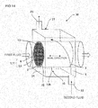
- Fig. 7A shows an embodiment where fins 12f are arranged inside the metal pipe 12.
- Fig. 7B is a cross-sectional view cut along a face perpendicular to the axial direction of the embodiment of Fig. 7A .
- Fins 12f are arranged in the end portion 12a inside the metal pipe 12.
- Fig. 8A shows an embodiment where fins 12f are arranged outside the metal pipe 12.
- Fig. 8B is a cross-sectional view cut along a face perpendicular to the axial direction of the embodiment shown in Fig. 8A .
- the fins 12f are arranged over almost the entire length in the axial direction outside the metal pipe 12.
- Fig. 9A is a schematic view showing another embodiment where fins 12f are arranged outside the metal pipe 12.
- Fig. 9B is a cross-sectional view cut along a face perpendicular to the axial direction of the embodiment shown in Fig. 9A .
- the shape of the fins 12f is not limited to those of the embodiments of Figs. 8B and 9B .
- Fig. 10A is a cross-sectional view cut along a face parallel to the axial direction, showing an embodiment where a step portion 12d is formed in the metal pipe 12.
- Fig. 10B is a cross-sectional view cut along a face perpendicular to the axial direction, showing the embodiment of Fig. 10A .
- the step portion 12d is formed to have a depressed shape toward inside.
- the portion having such a shape can be formed by a pressing method.
- the rigidity of the metal pipe 12 can be improved.
- a portion protruding toward outside may be formed in the metal pipe 12 as the step portion 12d.
- Fig. 12A shows an embodiment where a step portion 12d is formed in a cylindrical fashion from the vicinity of an end portion 2 of the honeycomb structure 1 to the end portion 12a of the metal pipe 12.
- the step portion 12d of the present embodiment has a shrunk diameter from the vicinity of the end portion 2 of the honeycomb structure 1 to the end portion 12a of the metal pipe 12, and the step portion 12d is formed in a cylindrical shape (in a circular cylindrical shape). By forming such a step portion 12d, stress of the metal pipe 12 can be relaxed.
- Fig. 12B shows an embodiment where a step portion 12d is formed in the metal pipe 12 in the vicinity of an end portion 2 of the honeycomb structure 1.
- Fig. 12C shows an embodiment where, a step portion 12d is formed in the end portion 12a of the metal pipe 12.
- Fig. 13A shows an embodiment where the edge of the outer peripheral wall 7 in the axial direction of the honeycomb structure 1 was chamfered.
- a C shape C-shape portion 7c
- an R shape R-shape portion 7r
- the inner diameter of the metal pipe 12 at a portion covering the edge of the outer peripheral wall 7 of the honeycomb structure 1 is at least 1.01 times the inner diameter of the other portion. Such constitution enables to inhibit chipping of the edge of the outer peripheral wall 7 of the honeycomb structure 1.
- Fig. 14 shows a perspective view of a heat exchanger 30 including a heat conduction member 10 of the present invention.
- the heat exchanger 30 is formed of the heat conduction member 10 (honeycomb structure 1 + intermediate member 13 + metal pipe 12) and a casing 21 containing the heat conduction member 10 therein.
- the cells 3 of the honeycomb structure 1 of the cylindrical ceramic body 11 serve as the first fluid-flowing portion 5 where the first fluid flows therethrough.
- the heat exchanger 30 is constituted so that the first fluid having higher temperature than the second fluid flows through the cells 3 of the honeycomb structure 1.
- the inlet 22 and the outlet 23 for the second fluid are formed in the casing 21, and the second fluid flows on the outer peripheral face 12h of the metal pipe 12 of the heat conduction member 10.
- the second fluid-flowing portion 6 is formed by the inside face 24 of the casing 21 and the outer peripheral phase 12h of the metal pipe 12.
- the second fluid-flowing portion 6 is a portion for the second fluid; is formed by the casing 21 and the outer peripheral face 12h of the metal pipe 12; is separated from the first fluid-flowing portion 5 by the partition walls 4 of the honeycomb structure 1, intermediate member 13, and the metal pipe 12 to be able to transfer heat; receives heat of the first fluid flowing through the first fluid-flowing portion 5 by means of the partition walls 4, the intermediate member 13, and the metal pipe 12; and transfers heat to the body to be heated, which is the second fluid.
- the first fluid and the second fluid are completely separated from each other lest these fluids should be mixed together.
- the first fluid-flowing portion 5 is constituted to have a honeycomb structure, and, in the case of a honeycomb structure, the fluid cannot flow into another cell 3 due to the partition walls 4 when the fluid passes through the cells 3, and the fluid linearly proceeds from the inlet to the outlet of the honeycomb structure 1.
- the honeycomb structure 1 of the heat exchanger 30 of the present invention is not plugged, and the heat transfer area of the fluid is increased, and thereby the size of the heat exchanger 30 can be reduced. This enables to increase the heat transfer amount per unit volume of the heat exchanger 30. Further, since it is not necessary to perform processing such as formation of plugging portions and formation of slits in the honeycomb structure 1, the heat exchanger 30 enables to reduce the production costs.
- the heat exchanger 30 allows the first fluid having higher temperature than the second fluid to flow and allows heat conduction from the first fluid to the second fluid.
- gas is allowed to flow as the first fluid while liquid is allowed to flow as the second fluid, the heat exchange between the first fluid and the second fluid can efficiently be conducted. That is, the heat exchanger 30 of the present invention can be applied as a gas/liquid heat exchanger.
- the heating body which is the first fluid allowed to flow through the heat exchanger 30 of the present invention having the constitution as described above as long as it is a medium having heat, such as gas and liquid.
- the examples include automobile exhaust gas as the gas.
- the body to be heated which is the second fluid receiving heat from the heating body (exchanging heat), as a medium as long as the temperature is lower than that of the heating body.
- the kneaded material was extruded to form a honeycomb formed body.
- the shape and thickness of the outer peripheral wall, the thickness of the partition wall, the cell shape, and the cell density were made desirable.
- a die made of superhard alloy which hardly abrades away was used.
- the outer peripheral wall was made to have a cylindrical shape or a hollow quadrangular prism shape, and the portion inside the outer peripheral wall was formed to have a structure partitioned in a square lattice pattern by partition walls.
- partition walls were formed so that they are parallel to each other at regular interval in the directions perpendicular to each other and that they pass across the portion inside the outer peripheral wall. This made square the cross-sectional shape of the cells except for the cells in the outermost peripheral portion inside the outer peripheral wall.
- honeycomb formed body obtained by the extrusion was performed.
- the honeycomb formed body was dried by an electromagnetic wave heating method in the first place and then dried by an external heating method.
- the moisture corresponding to 97% of the entire moisture amount contained in the honeycomb formed body before drying was removed from the honeycomb formed body.
- degreasing of the honeycomb formed body was performed at 500°C for five hours in a nitrogen atmosphere.
- a lump of metal Si was put on the honeycomb structure obtained by the degreasing, and firing was performed at 1450°C for four hours in vacuum or in an inert gas of reduced pressure.
- the metal Si lump put on the honeycomb structure was melted, and the outer peripheral wall and the partition walls were impregnated with the metal Si.
- 80 parts by mass of the lump of metal Si was used with respect to 100 parts by mass of the honeycomb structure.
- honeycomb structure 1 made of silicon carbide and having a circular columnar (cylindrical) shape and, as the main body size, a diameter (outer diameter) of 40 mm and a length of 80 mm. That is, as the cylindrical ceramic body 11, the honeycomb structure 1 was used.
- the honeycomb structure 1 has a cell density of 23.3 cells/cm 2 , a thickness of the partition walls 4 (partition wall thickness) of 0.3 mm, and the honeycomb structure 1 has a heat conductivity of 150 kw/m ⁇ K.
- a graphite sheet with an acrylic adhesive material (HT-705A produced by OTSUKA ELCTRIC CO., LTD.) was bonded to the outer peripheral face 7h of the honeycomb structure 1.
- the graphite sheet had a heat conductivity of 6 W/m ⁇ K in the thickness direction and a Young's modulus of 0.1 GPa. Though the graphite sheet with an acrylic adhesive material was used at that time, it may be bonded by separately using a heat conductive adhesive.
- the temperature of the metal pipe 12 was raised to 1000°C by a high frequency heater, and the honeycomb structure 1 was inserted into the metal pipe 12 and subjected to shrink fitting.
- a metal pipe having a following diameter was used lest the pressure should be released.
- the outer diameter of the cylindrical ceramic body 11 was 42 mm
- the thermal expansion coefficient ⁇ of the cylindrical ceramic body 11 was 4 ⁇ 10 -6 /°C
- the thermal expansion coefficient ⁇ of the metal pipe 12 was 17 ⁇ 10 -6 /°C
- the thickness c of the graphite sheet was 0.2 mm
- 41.704 mm ⁇ D ⁇ 42.332 mm was used as the metal pipe 12.
- cylindrical ceramic body 11 honeycomb structure 1
- the cylindrical ceramic body 11 was the same as the Example 1.
- Example 2 In the same manner as in Example 1, there was manufactured a heat conductive member composed of a cylindrical ceramic body 11 (honeycomb structure 1) and a metal pipe 12 with no intermediate member 13 of a graphite sheet.
- Example 1 With regard to the samples of Example 1, Reference Example, and Comparative Example 1, there was measured a heat transfer efficiency to the second fluid at the time that the first fluid heated at 300°C was passed through the cells 3 of the honeycomb structure 1 of the heat conduction member 10. Specifically, it was performed as follows. Nitrogen gas was allowed to flow through the first fluid-flowing portion 5 of the honeycomb structure 1, and (cooling) water was allowed to flow through the second fluid-flowing portion 6 in the casing 21. Both the inlet temperature and flow rate of the first fluid and the second fluid into the honeycomb structure 1 were under the same conditions. Nitrogen gas (N 2 ) at 300°C as the first fluid was allowed to flow at a flow rate of 7.6 L/sec. with respect to the honeycomb structure 1.
- Example 1 used a sample having the second fluid passage on the outer periphery side of the heat conduction member 10 serving as the first fluid passage (see Fig. 14 ).
- Table 1 shows heat transfer efficiency.
- the heat transfer efficiency (%) was obtained by calculating each energy amount from ⁇ T°C (outlet temperature - inlet temperature of the honeycomb structure 1) of the first fluid (nitrogen gas) and the second fluid (water) and calculating with the formula 1.
- Heat transfer efficiency % inlet temperature of the first fluid gas - outlet temperature of the first fluid gas / inlet temperature of the first fluid gas - inlet temperature of the second fluid cooling water
- the heat conduction member with no graphite sheet has a lower heat transfer efficiency by 5.0%.
- the graphite sheet therein Example 1
- the decrease was suppressed to 2.6%. This enabled to confirm the improvement in thermal adhesiveness by the graphite sheet. That is, in the case of covering the cylindrical ceramic body 11 with a metal pipe, by using a graphite sheet therebetween, the thermally bonded state can be improved.
- each of the other intermediate members 13 was subjected to the same heat transfer test to obtain the heat transfer efficiency.
- presence/absence of crack generation in the cylindrical ceramic body 11 was checked. It is shown in Table 2.
- Example 1, Reference Example, and Comparative Example 1 of Table 2 were the same as in Table 1.
- the structure was "cylindrical ceramic body 11 + intermediate member 13 + metal pipe 12" except for Reference Example and Comparative Example 1.
- the structure of Reference Example was a single body of a cylindrical ceramic body 11, and the structure of Comparative Example 1 was cylindrical ceramic body 11 + metal pipe 12 with no intermediate member 13.
- a heat exchanger of the present invention in the automobile field or the industrial field as long as heat is exchanged between the heating body (high temperature side) and the body to be heated (low temperature side).
- it is suitable when at least one of the heating body and the body to be heated is liquid.
- it can be used in order to improve fuel efficiency of automobiles.
Abstract
Description
- The present invention relates to a heat conduction member where a cylindrical ceramic body is covered with a metal pipe.
- Heat can be used effectively by heat exchange from a high temperature fluid to a low temperature fluid. For example, there is a heat recovery technique of recovering heat from high temperature gas such as combustion exhaust gas of an engine or the like. As a gas/liquid heat exchanger, a fin-provided tube-shaped heat exchanger of an automobile radiator, an air-conditioning outdoor unit, or the like is general. However, for recovering heat from gas such as automobile exhaust gas, it is difficult to use a general metal heat exchanger at high temperature because it has poor heat resistance. Therefore, heat resistant metals and ceramic materials having heat resistance, thermal shock resistance, corrosion resistance, and the like are suitable. However, heat resistant metals have problems such as high costs, difficulty in processing, high weight because of high density, and low heat conduction.
- Therefore, a heat recovery technique using a ceramic material has been developed. For example, there is a technique of performing heat exchange by the use of a cylindrical ceramic body. In this case, heat exchange is performed by allowing the first fluid to flow through the inside portion of the cylindrical ceramic body and the second fluid to flow through the outside portion. In the case of heat exchange using a cylindrical ceramic body between gas and liquid, it is necessary to shield the cylindrical ceramic body lest the cylindrical ceramic body should have liquid leakage to mix the two fluids together.
-
Patent Document 1 discloses a technique of recovering heat by integrating a ceramic honeycomb structure as a cylindrical ceramic body with a metal base material (metal pipe). - Patent Document 1:
JP-A-9-327627 - However, in the case of integrating a ceramic honeycomb structure with a metal base material (metal pipe) as in the
Patent Document 1, there arise a problem of thermal expansion caused in use to deteriorate adhesion between the honeycomb structure and the metal base material and a problem of thermal stress generation to cause breakage in the honeycomb structure. - In addition, in the case of integrating a cylindrical ceramic body with a metal pipe by press-fitting, the durability is reduced because of increase in thermal resistance by insufficient adhesion, breakage of heat conduction member by excessive precompression, and large residual stress remaining in the metal pipe.
- In the case of integrating a cylindrical ceramic body with a metal pipe by brazing, it is difficult to secure wettability, and stress is caused by a thermal expansion difference.
- The challenge of the present invention is to provide a heat conduction member inhibiting stress generation due to a thermal expansion difference while maintaining a thermal coupling state in the case of covering the cylindrical ceramic body with a metal pipe.
- The inventors found out that the aforementioned problem can be solved by arranging an intermediate member made of a material having a Young's modulus of 150 GPa or less between the cylindrical ceramic body and the metal pipe on the outer peripheral side of the cylindrical ceramic body. That is, according to the present invention, there are provided the following heat conduction members.
- [1] A heat conduction member comprising: a cylindrical ceramic body having passages passing through from one end face to the other end face and allowing a first fluid as a heating body to flow therethrough, a metal pipe on the outer periphery side of the cylindrical ceramic body, and an intermediate member held between the cylindrical ceramic body and the metal pipe and made of material having at least a part having a Young's modulus of 150 GPa or less; wherein the first fluid is allowed to flow through the inside of the cylindrical ceramic body while the second fluid having lower temperature than that of the first fluid is allowed to flow on the outer peripheral face side of the metal pipe to perform heat exchange between the first fluid and the second fluid.
- [2] The heat conduction member according to the above [1], wherein the intermediate member is brought into contact with at least a part of the metal pipe and the cylindrical ceramic body.
- [3] The heat conduction member according to the above [1] or [2], wherein the intermediate member has at least a part having a heat conductivity of 1 W/m·K or more.
- [4] The heat conduction member according to any one of the above [1] to [3], wherein the intermediate member is of the graphite sheet, has a Young's modulus of 1 GPa or less, and has a heat conductivity of 3 W/m·K or more in the thickness direction.
- [5] The heat conduction member according to any one of the above [1] to [4], wherein the cylindrical ceramic body has a heat conductivity of 100 W/m·K or more.
- [6] The heat conduction member according to any one of the above [1] to [5], wherein the cylindrical ceramic body is a honeycomb structure having partition walls of a porous body and a plurality of cells functioning as fluid passages separated and formed by the partition walls.
- [7] The heat conduction member according to the above [6], wherein the honeycomb structure contains silicon carbide as a main component.
- Adhesion is improved by arranging an intermediate member made of a material having a Young's modulus of 150 GPa between the cylindrical ceramic body and the metal pipe on the outer periphery side of the cylindrical ceramic body. This improves heat conductance, and heat in the cylindrical ceramic body can efficiently be discharged outside the metal pipe. In addition, since the heat conductance is excellent in the axial (longitudinal) direction, heat on the tip (inlet) side can be released to the rear (outlet) side. In the case that a graphite sheet is used as the intermediate member, since side slipping is possible by the graphite sheet, stress due to the thermal expansion difference between the cylindrical ceramic body and the metal pipe is hardly caused. Though the joint portion of the metal pipe and cylindrical ceramic body is at risk of being exposed to a temperature up to about 150°C, graphite has a sufficient heat resistant temperature of 400°C or more. In addition, it is in no danger of corrosion.
-
- [
Fig. 1] Fig. 1 is a schematic view from one end face in the axial direction, showing a heat conduction member of the present invention. - [
Fig. 2] Fig. 2 is a perspective view showing a heat conduction member of the present invention. - [
Fig. 3] Fig. 3 is a schematic view from one end face in the axial direction, showing another embodiment of a heat conduction member of the present invention. - [
Fig. 4] Fig. 4 is a schematic view for explaining the second method for integration. - [
Fig. 5] Fig. 5 is a cross-sectional view cut along a face parallel to the axial direction, showing another embodiment of a heat conduction member of the present invention. - [
Fig. 6A] Fig. 6A is a cross-sectional view cut along a face parallel to the axial direction, showing an embodiment where the intermediate member is held only in a part. - [
Fig. 6B] Fig. 6B is a cross-sectional view cut along a face perpendicular to the axial direction, showing another embodiment where the intermediate member is held only in a part. - [
Fig. 7A] Fig. 7A is a cross-sectional view cut along a face parallel to the axial direction, showing an embodiment where fins are arranged inside the metal pipe. - [
Fig. 7B] Fig. 7B is a cross-sectional view cut along a face perpendicular to the axial direction, showing an embodiment where fins are arranged inside the metal pipe. - [
Fig. 8A] Fig. 8A is a cross-sectional view cut along a face parallel to the axial direction, showing an embodiment where fins are arranged outside the metal pipe. - [
Fig. 8B] Fig. 8B is a cross-sectional view cut along a face perpendicular to the axial direction, showing an embodiment where fins are arranged outside the metal pipe. - [
Fig. 9A] Fig. 9A is a schematic view showing another embodiment where fins are arranged outside the metal pipe. - [
Fig. 9B] Fig. 9B is a cross-sectional view cut along a face perpendicular to the axial direction, showing another embodiment where fins are arranged outside the metal pipe. - [
Fig. 10A] Fig. 10A is a cross-sectional view cut along a face parallel to the axial direction, showing an embodiment where a step portion is formed in the metal pipe. - [
Fig. 10B] Fig. 10B is a cross-sectional view cut along a face perpendicular to the axial direction, showing an embodiment where a step portion is formed in the metal pipe. - [
Fig. 11] Fig. 11 is a cross-sectional view cut along a face parallel to the axial direction, showing another embodiment where a step portion is formed in the metal pipe. - [
Fig. 12A] Fig. 12A is a cross-sectional view cut along a face parallel to the axial direction, showing an embodiment where a step portion is formed from the vicinity of an end portion of the honeycomb structure to the end portion of the metal pipe. - [
Fig. 12B] Fig. 12B is a cross-sectional view cut along a face parallel to the axial direction, showing an embodiment where a step portion is formed in the metal pipe in the vicinity of an end portion of the honeycomb structure. - [
Fig. 12C] Fig. 12C is a cross-sectional view cut along a face parallel to the axial direction, showing an embodiment where a step portion is formed in the end portion of the metal pipe. - [
Fig. 13A] Fig. 13A is a cross-sectional view showing an embodiment where the edge in the axial direction of the honeycomb structure was chamfered. - [
Fig. 13B] Fig. 13B is a cross-sectional view showing an embodiment having a structure where the inner diameter of the metal pipe at a portion covering the edge of the honeycomb structure is at least 1.01 times the inner diameter of the other portion. - [
Fig. 14] Fig. 14 is a schematic view showing a heat exchanger including a heat conduction member of the present invention. - Hereinbelow, embodiments of the present invention will be described with referring to drawings. The present invention is not limited to the following embodiments, and changes, modifications, and improvements may be added as long as they do not deviate from the scope of the invention.
-
Fig. 1 shows a view from one end face in the axial direction of aheat conduction member 10 of the present invention, andFig. 2 shows a perspective view of theheat conduction member 10. Theheat conduction member 10 is provided with a cylindricalceramic body 11, ametal pipe 12 on the outer periphery side of the cylindricalceramic body 11, and theintermediate member 13 held between the cylindricalceramic body 11 and themetal pipe 12. The cylindricalceramic body 11 has passages passing through from oneend face 2 to theother end face 2 and allowing a first fluid as a heating body to flow therethrough. Theintermediate member 13 is made of a material having at least a part having a Young's modulus of 150 GPa or less. By allowing the first fluid to flow through the inside of the cylindricalceramic body 11 and the second fluid having lower temperature than that of the first fluid to flow on the outerperipheral face 12h side of themetal pipe 12, theheat conduction member 10 can perform heat exchange between the first fluid and the second fluid. Since theheat conduction member 10 is provided with themetal pipe 12 on the outer periphery side of the cylindricalceramic body 11, the first fluid and the second fluid are completely separated from each other and do not mix together. In addiction, since theheat conduction member 10 is provided with themetal pipe 12, processing depending on the installation site and the installation method is easy with high flexibility. Theheat conduction member 10 is strong against shock from outside since the cylindricalceramic body 11 can be protected by themetal pipe 12. - By the use of the
intermediate member 13 of a material having a Young' s modulus of 150 GPa for theheat conduction member 10, adhesion between themetal pipe 12 and the cylindricalceramic body 11 can be improved, and heat conductance can be enhanced. In this case, it is preferable that theintermediate member 13 is brought into contact with at least a part of themetal pipe 12 and the cylindricalceramic body 11 to obtain good heat conductance of theheat conduction member 10. - Further, it is preferable that the
intermediate member 13 has at least a part having a heat conductivity of 1 W/m·K or more. When the heat conductivity of theintermediate member 13 is 1 W/m·K or more, the heat conductance of theheat conduction member 10 can be enhanced. - As the
intermediate member 13, a graphite sheet, a metal sheet, a gel sheet, an elastoplastic fluid, and the like can be mentioned. As the metal constituting the metal sheet, Au, Ag, Cu, Al, and the like can be mentioned. The elastoplastic fluid is a material which behaves as a solid (having an elastic modulus) without plastic deformation when a small force is applied and which deforms as a fluid with freely changing the shape when a large force is applied. And grease and the like can be mentioned for example. In consideration of adhesion, heat conductance, and the like, a graphite sheet is preferably used as theintermediate member 13. Hereinbelow, description of an example will be given with a graphite sheet as theintermediate member 13. - The
metal pipe 12 and the cylindricalceramic body 11 can be engaged with each other by, for example, shrink fitting in the state of holding theintermediate member 13 of a graphite sheet therebetween (first method for integration described later). By integrating themetal pipe 12 with the cylindricalceramic body 11, the first fluid and the second fluid are inhibited from mixing together. By the shrink fitting with theintermediate member 13 as the graphite sheet being held, pressure is applied to the graphite sheet in the environment at room temperature to 150°C in use of the joint portion of themetal pipe 12 and cylindricalceramic body 11 to be able to transfer heat. - The graphite sheet in the present specification means a graphite containing expanding graphite as the main component and being processed to have a sheet shape by rolling or a sheet-shaped one obtained by thermally decomposing a polymer film. The graphite sheet includes a graphite sheet and a carbon sheet. It is preferable that the graphite sheet has a Young's modulus of 1 GPa or less in the thickness direction and a heat conductivity of 1 W/m· K or more in the thickness direction. The heat conductivity in the thickness direction is more preferably 3 to 10 W/m· K. The heat conductivity in the in-plane direction is preferably 5 to 1600 W/m·K, more preferably 100 to 400 W/m· K.
- The Young's modulus of the graphite sheet is preferably 1 MPa to 1 GPa. It is more preferably 5 MPa to 500 MPa, furthermore preferably 10 MPa to 200 MPa. When the Young's modulus is 1 MPa or more, the graphite has sufficient density and good heat conductance. On the other hand, when it is 500 MPa or less, even a thin graphite sheet sufficiently causes elastic deformation upon shrink fitting, and adhesion and a stress relaxation effect of the
metal pipe 12 can be obtained. - The thickness of the graphite sheet is preferably 25 µm to 1 mm, more preferably 25 µm to 500 µm, furthermore preferably 50 µm to 250 µm. The thinner the graphite sheet is, the more expensive it is. When it is thick, heat resistance is generated. By using the graphite sheet within this range, the heat conductance becomes good, and the heat in the cylindrical
ceramic body 11 can efficiently be discharged outside themetal pipe 12. - The heat conductivity of the cylindrical
ceramic body 11 is preferably 100 W/m·K or more. It is more preferably 120 to 300 W/m·K, furthermore preferably 150 to 300 W/m·K. This range can improve heat conductance, and the heat in the cylindricalceramic body 11 can efficiently be discharged outside themetal pipe 12. - The cylindrical
ceramic body 11 is formed of ceramic into a cylindrical shape and has fluid passages passing through from oneend face 2 to the other end face 2 in the axial direction. The cylindrical shape is not limited to a circular cylindrical shape (circular columnar shape) and may be a shape where a cross section perpendicular to the axial (longitudinal) direction has an elliptic shape, or an oval shape where circular arcs are compounded, or a prism shape where a cross section has a polygonal shape such as a quadrangular shape. It is preferable that the cylindricalceramic body 11 is ahoneycomb structure 1 havingpartition walls 4 of a porous body and a plurality of cells functioning as fluid passages separated and formed by thepartition walls 4. By having thepartition walls 4, the heat from the fluid passing through the inside portion of the cylindricalceramic body 11 can efficiently be collected and transferred outside.Figs. 1 and 2 show an embodiment using ahoneycomb structure 1 having a large number of cells formed therein as the cylindricalceramic body 11.Fig. 3 shows an embodiment using a hollow ceramic pipe having only the outerperipheral wall 7 with nopartition wall 4 as the cylindricalceramic body 11. - For the cylindrical
ceramic body 11, it is preferable to use a ceramic having excellent heat resistance. In particular, if heat conductance is considered, the main component is preferably SiC (silicon carbide) having high heat conductance. The main component means that 50 mass% or more of the cylindricalceramic body 11 is silicon carbide. - However, it is not necessary that the entire cylindrical
ceramic body 11 is constituted of SiC (silicon carbide) as long as SiC (silicon carbide) is contained in the main body. That is, the cylindricalceramic body 11 is preferably formed of ceramic containing SiC (silicon carbide). - Incidentally, since a porous body even made of SiC (silicon carbide) cannot obtain high heat conductivity, it is preferable to impregnate the cylindrical
ceramic body 11 with silicon in the manufacturing process to obtain a dense structure. The dense structure enables to obtain high heat conductivity. For example, in the case of SiC (silicon carbide) porous body, the heat conductivity is about 20 W/m· K. However, by the densification, it can be about 150 W/m· K. - As the cylindrical
ceramic body 11, Si-impregnated SiC, (Si+Al)-impregnated SiC, metal composite SiC, Si3N4, SiC, or the like can be employed, but to form a dense structure to obtain high heat conductivity, Si-impregnated SiC or (Si+Al)-impregnated SiC can be employed. Since Si-impregnated SiC has a structure where a SiC particle surface is surrounded by a coagulation of a metal silicon melt and where SiC particles are unitarily joined by means of metal silicon, the silicon carbide is shielded from the atmosphere containing oxygen and thereby inhibited from being oxidized. Further, though SiC has characteristics of high heat conductivity and easy heat release, Si-impregnated SiC is densely formed and has sufficient strength as a heat transfer member while showing high heat conductivity and heat resistance. That is, the cylindricalceramic body 11 formed of a Si-SiC based (Si-impregnated SiC, (Si+Al)-impregnated SiC) material shows high heat conductivity in addition to excellent properties of heat resistance, heat shock resistance, oxidation resistance, and corrosion resistance against acid and alkali. - In the case of forming the cylindrical
ceramic body 11 as ahoneycomb structure 1 having a plurality ofcells 3 functioning as passages separated and formed by thepartition walls 4, a desired cell shape may appropriately be selected from a circle, an ellipse, a triangle, a quadrangle, a hexagon, other polygons, and the like. - There is no particular limitation on the cell density (i.e., the number of cells per unit cross-sectional area) of the
honeycomb structure 1, and it can appropriately be designed according to the purpose. However, it is preferably within the range from 25 to 2000 cells/in2 (4 to 320 cells/cm2). When the cell density is above 25 cells/in2, the strength of thepartition walls 4 and, eventually, the strength of thehoneycomb structure 1 itself and an effective GSA (geometric surface area) can be made sufficient. On the other hand, when the cell density is 2000 cells/in2 or less, pressure loss at the time that a heat medium flows is reduced. - The cell number per
honeycomb structure 1 is preferably 1 to 10,000, particularly preferably 200 to 2,000. When the cell number is too large, since the honeycomb structure itself becomes large, the heat conduction distance from the first fluid side to the second fluid side becomes long to make the heat flux small due to the increase of heat conduction loss. When the cell number is small, the heat conduction area on the first fluid side becomes small, and heat resistance on the first fluid side cannot be reduced, thereby reducing the heat flux. - There is no particular limitation on the thickness of the partition walls 4 (wall thickness) of the
cells 3 of thehoneycomb structure 1, and it may appropriately be designed according to the purpose. The wall thickness is preferably 50 µm to 2 mm, more preferably 60 µm to 500 µm. The wall thickness of 50 µm or more improves mechanical strength and inhibits breakage due to shock or heat stress. On the other hand, the wall thickness of 2 mm or less reduces pressure loss of the fluid due to the increase in the proportion of cell capacity on the honeycomb structure side, which enables to raise the heat exchange rate. - The density of the
partition walls 4 of thecells 3 of thehoneycomb structure 1 is preferably 0.5 to 5 g/cm3. In the case of 0.5 g/cm3 or more, strength of thepartition walls 4 becomes sufficient, and it can inhibit thepartition walls 4 from breaking due to pressure at the time that the first fluid passes through the passages. When the density is 5 g/cm3 or less, thehoneycomb structure 1 itself does not become heavy, and the weight can be reduced. By the density within the aforementioned range, thehoneycomb structure 1 can be made strong. In addition, an effect of improving the heat conductivity can be obtained. - In the case that the first fluid (high temperature side) passed through the heat exchanger 30 (see
Fig. 14 ) is exhaust gas, it is preferable that a catalyst is loaded on the wall faces inside thecells 3 of thehoneycomb structure 1 where the first fluid (high temperature side) passes. This is because it becomes possible to change reaction heat (exothermic reaction) generated upon exhaust gas purification in addition to the role of exhaust gas purification. It is preferable that the catalyst contains at least one element selected from the group consisting of noble metals (platinum, rhodium, palladium, ruthenium, indium, silver, and gold), aluminum, nickel, zirconium, titanium, cerium, cobalt, manganese, zinc, copper, zinc, iron, niobium, magnesium, lanthanum, samarium, bismuth, and barium. These may be metals, oxides, or other compounds. - The amount of the catalyst (catalyst metal + carrier) loaded on the
partition walls 4 of thecells 3 of the firstfluid flowing portion 5, where the first fluid (high temperature side) passes, of thehoneycomb structure 1 is preferably 10 to 400 g/L, more preferably 0.1 to 5 g/L in the case of a noble metal. When the amount of the catalyst (catalyst metal + carrier) is 10 g/L or more, the catalyst function is sufficiently exhibited. On the other hand, when it is 400 g/L or less, the pressure loss does not become too large, and increase of the production costs can be suppressed. - As the metal pipe 42, one having heat resistance and corrosion resistance is preferable, and, for example, a SUS pipe, a copper pipe, or a brass pipe can be used. The temperature of the coolant water as the second fluid flowing on the outer
peripheral face 12h of themetal pipe 12 can rise up to about 120°C, and it is preferable to specify the diameter of themetal pipe 12 to the range of the formula described below lest the pressure between the cylindricalceramic body 11 and themetal pipe 12 should escape due to the difference of the thermal expansion coefficient. That is, when the outer diameter of the cylindricalceramic body 11 at 25°C of room temperature is d, the thickness of graphite sheet is c, the thermal expansion coefficient of the cylindricalceramic body 11 is α, the thermal expansion coefficient of themetal pipe 12 is β, and the temperature of the shrink fitting is 1000°C, it is preferable to set the inner diameter D of themetal pipe 12 so that
d + 2 × c - 975 × (3 × d < D < d + 2 × c - 125 × (β - α) × d can be satisfied. - The aforementioned inner diameter D of the
metal pipe 12 is within the range where the pressure of tight fitting is securely applied in the temperature range from ordinary temperature to 150°C, which is conceivable in the joint portion between the cylindricalceramic body 11 and themetal pipe 12. The inner diameter D of themetal pipe 12 in this range enables to have no tensile stress remaining more than necessary in themetal pipe 12. Specifically, for example, when the outer diameter of the cylindricalceramic body 11 is 42 mm, the thermal expansion coefficient α of the cylindricalceramic body 11 is 4.0×10⁻⁶, the thermal expansion coefficient β of themetal pipe 12 is 17×10-6, and the thickness c of the graphite sheet is 0.2 mm, D is larger than 41.704 mm and smaller than 42.332 mm. - Next, a method for manufacturing a
heat conduction member 10 of the present invention will be described. In the first place, SiC powders having different average particle diameters are mixed together to prepare a mixture of SiC powders. A binder and water are mixed with the mixture of SiC powders, and they are kneaded with a kneader to obtain a kneaded material. The kneaded material is put in a vacuum kneader to prepare a kneaded material having a circular columnar shape. - Next, the kneaded material is extruded to form a honeycomb formed body. In the extrusion, by selecting a die and a jig having appropriate shapes, the shape and the thickness of the outer peripheral wall, partition wall thickness, cell shape, cell density, and the like can be made desirable. It is preferable to use a die made of superhard alloy which hardly abrades away. The honeycomb formed body is formed so as to have a structure where the outer peripheral wall has a cylindrical shape or a quadrangular prism shape and where the portion inside the outer peripheral wall is partitioned by partition walls to have a square lattice shape. These partition walls are formed to be parallel to each other at regular intervals in each of the directions perpendicular to each other and to pass straight across the portion inside the outer peripheral wall. This enables to obtain a square cross-sectional shape of the cells in the portion inside the outer peripheral wall except for the outermost peripheral portion.
- Next, the honeycomb formed body obtained by extrusion is dried. In the first place, the honeycomb formed body is dried in an electromagnetic wave heating method and then dried in the external heating method. By such two-step drying, moisture corresponding to 97% of the amount of the entire moisture contained in the honeycomb formed body before drying is removed from the honeycomb formed body.
- Next, the honeycomb formed body is degreased in a nitrogen atmosphere. Further, a lump of metal Si is put on the honeycomb structure obtained by the degreasing and fired in vacuum or an inert gas of reduced pressure. During the firing, the lump of the metal Si put on the honeycomb structure is melted to impregnate the outer
peripheral wall 7 and thepartition walls 4 with metal Si. For example, when the heat conductivity of the outerperipheral wall 7 and thepartition walls 4 is 100 W/m·K, the lump of metal Si having 70 parts by mass with respect to 100 parts by mass of the honeycomb structure is used. When the heat conductivity of the outerperipheral wall 7 and thepartition walls 4 is made 150 W/m·K, the lump of metal Si having 80 parts by mass with respect to 100 parts by mass of the honeycomb structure is used. - Next, a method of integrating the
honeycomb structure 1 manufactured as described above, theintermediate member 13, and themetal pipe 12 will be described. In the first method, first, a graphite sheet used as theintermediate member 13 is wrapped around the outerperipheral face 7h of the outerperipheral wall 7 of thehoneycomb structure 1. At this time, it may be bonded by the use of an adhesive. By using the adhesive, the graphite sheet can be bonded uniformly. It is desirable that the adhesive is sufficiently thin and has good heat conductance. In addition, since a tough fitting state is obtained after shrink fitting, the adhesion may be entire face adhesion or partial adhesion. Then, the temperature of themetal pipe 12 is raised up to about 1000°C with a high frequency heater. Then, the honeycomb structure is inserted into themetal pipe 12, and they are integrated by shrink fitting to form aheat conduction member 10. - The second method for integrating the
honeycomb structure 1, theintermediate member 13, and themetal pipe 12 will be described. In the second method, a metal plate (flat plate) is used to obtain ametal pipe 12. In the first place, a graphite sheet is wrapped around the outerperipheral face 7h of the outerperipheral wall 7 of thehoneycomb structure 1. Next, the metal plate (flat plate) is wrapped around thehoneycomb structure 1 with applying pressure and tightened (seeFig. 4 ). Then, theend portions 12a of the metal plate having a cylindrical shape by being wrapped around thehoneycomb structure 1 are joined to each other to obtain ametal pipe 12. As the joining of theend portions 12a of the metal plate, for example, laser welding can be employed. - The third method of integrating the
honeycomb structure 1, theintermediate member 13, and themetal pipe 12 will be described. The third method is a hot plastic processing method. In the first place, a graphite sheet is wrapped around the outerperipheral face 7h of the outerperipheral wall 7 of thehoneycomb structure 1. Next, ahoneycomb structure 1 is installed inside themetal pipe 12. The inner diameter of themetal pipe 12 is sufficiently large in comparison with the outer peripheral diameter of thehoneycomb structure 1. Next, the temperature of the region where thehoneycomb structure 1 is installed of themetal pipe 12 is raised to about 400 to 1100°C. By pulling both the end portions of the metal pipe while locally heating themetal pipe 12, the diameter of themetal pipe 12 shrinks. By cooling after themetal pipe 12 and thehoneycomb structure 1 are integrated, aheat conduction member 10 can be formed. - In a
heat conduction member 10 of the present invention, by arranging theintermediate member 13 of a graphite sheet or the like having a low Young's modulus between the cylindricalceramic body 11 and themetal pipe 12 on the outer peripheral side, adhesion is enhanced. This enables the heat conductivity in the thickness direction (diametral direction of the pipe) to be 3 W/m·K or more, and the heat conductance is good. In addition, the heat conductivity in the longitudinal (axial) direction can be made 250 W/m·K or more, and heat conductivity is good. Since side slipping is possible by the graphite sheet and the like, stress due to thermal expansion difference between the cylindricalceramic body 11 and themetal pipe 12 is hardly caused. Therefore, heat resistance is practically sufficient. -
Fig. 5 is a cross-sectional view cut along a face parallel to the axial direction, showing another embodiment of aheat conduction member 10 of the present invention. As shown inFig. 5 , themetal pipe 12 is longer than the length in the axial direction of thehoneycomb structure 1. By such constitution, theend portions 12a of themetal pipe 12 can easily be processed according to the installation site and the use of theheat conduction member 10. -
Fig. 6A is a cross-sectional view cut along a face parallel to the axial direction, showing an embodiment where theintermediate member 13 is held only in a part.Fig. 6B is a cross-sectional view cut along a face perpendicular to the axial direction, showing another embodiment where theintermediate member 13 is held only in a part. Theintermediate member 13 does not have to be arranged entirely over thehoneycomb structure 1 as shown inFigs. 6A and 6B . Even in such an embodiment, effects of relaxing thermal stress and improving heat conductance efficiency can be obtained. Theintermediate member 13 may be mesh-shaped. -
Fig. 7A shows an embodiment wherefins 12f are arranged inside themetal pipe 12.Fig. 7B is a cross-sectional view cut along a face perpendicular to the axial direction of the embodiment ofFig. 7A .Fins 12f are arranged in theend portion 12a inside themetal pipe 12. By thus arranging thefins 12f in themetal pipe 12, the rigidity of the metal pipe can be improved. -
Fig. 8A shows an embodiment wherefins 12f are arranged outside themetal pipe 12.Fig. 8B is a cross-sectional view cut along a face perpendicular to the axial direction of the embodiment shown inFig. 8A . Thefins 12f are arranged over almost the entire length in the axial direction outside themetal pipe 12. By thus arranging thefins 12f in themetal pipe 12, the rigidity of the metal pipe can be improved. -
Fig. 9A is a schematic view showing another embodiment wherefins 12f are arranged outside themetal pipe 12.Fig. 9B is a cross-sectional view cut along a face perpendicular to the axial direction of the embodiment shown inFig. 9A . The shape of thefins 12f is not limited to those of the embodiments ofFigs. 8B and 9B . -
Fig. 10A is a cross-sectional view cut along a face parallel to the axial direction, showing an embodiment where astep portion 12d is formed in themetal pipe 12.Fig. 10B is a cross-sectional view cut along a face perpendicular to the axial direction, showing the embodiment ofFig. 10A . In this embodiment, thestep portion 12d is formed to have a depressed shape toward inside. The portion having such a shape can be formed by a pressing method. By arranging the depressed portion, the rigidity of themetal pipe 12 can be improved. As shown inFig. 11 , a portion protruding toward outside may be formed in themetal pipe 12 as thestep portion 12d. -
Fig. 12A shows an embodiment where astep portion 12d is formed in a cylindrical fashion from the vicinity of anend portion 2 of thehoneycomb structure 1 to theend portion 12a of themetal pipe 12. Thestep portion 12d of the present embodiment has a shrunk diameter from the vicinity of theend portion 2 of thehoneycomb structure 1 to theend portion 12a of themetal pipe 12, and thestep portion 12d is formed in a cylindrical shape (in a circular cylindrical shape). By forming such astep portion 12d, stress of themetal pipe 12 can be relaxed. -
Fig. 12B shows an embodiment where astep portion 12d is formed in themetal pipe 12 in the vicinity of anend portion 2 of thehoneycomb structure 1. By forming such astep portion 12d, stress of themetal pipe 12 can be relaxed. -
Fig. 12C shows an embodiment where, astep portion 12d is formed in theend portion 12a of themetal pipe 12. By forming such astep portion 12d, stress of themetal pipe 12 can be relaxed. -
Fig. 13A shows an embodiment where the edge of the outerperipheral wall 7 in the axial direction of thehoneycomb structure 1 was chamfered. As the shape of the edge, a C shape (C-shape portion 7c) or an R shape (R-shape portion 7r) can be mentioned. By thus forming the edge to have a chamfered shape, chipping of the edge of thehoneycomb structure 1 can be inhibited. - In addition, as shown in
Fig. 13B , it is preferable to constitute so that the inner diameter of themetal pipe 12 at a portion covering the edge of the outerperipheral wall 7 of thehoneycomb structure 1 is at least 1.01 times the inner diameter of the other portion. Such constitution enables to inhibit chipping of the edge of the outerperipheral wall 7 of thehoneycomb structure 1. -
Fig. 14 shows a perspective view of aheat exchanger 30 including aheat conduction member 10 of the present invention. As shown inFig. 14 , theheat exchanger 30 is formed of the heat conduction member 10 (honeycomb structure 1 +intermediate member 13 + metal pipe 12) and acasing 21 containing theheat conduction member 10 therein. Thecells 3 of thehoneycomb structure 1 of the cylindricalceramic body 11 serve as the first fluid-flowingportion 5 where the first fluid flows therethrough. Theheat exchanger 30 is constituted so that the first fluid having higher temperature than the second fluid flows through thecells 3 of thehoneycomb structure 1. In addition, theinlet 22 and theoutlet 23 for the second fluid are formed in thecasing 21, and the second fluid flows on the outerperipheral face 12h of themetal pipe 12 of theheat conduction member 10. - That is, the second fluid-flowing
portion 6 is formed by theinside face 24 of thecasing 21 and the outerperipheral phase 12h of themetal pipe 12. The second fluid-flowingportion 6 is a portion for the second fluid; is formed by thecasing 21 and the outerperipheral face 12h of themetal pipe 12; is separated from the first fluid-flowingportion 5 by thepartition walls 4 of thehoneycomb structure 1,intermediate member 13, and themetal pipe 12 to be able to transfer heat; receives heat of the first fluid flowing through the first fluid-flowingportion 5 by means of thepartition walls 4, theintermediate member 13, and themetal pipe 12; and transfers heat to the body to be heated, which is the second fluid. The first fluid and the second fluid are completely separated from each other lest these fluids should be mixed together. - The first fluid-flowing
portion 5 is constituted to have a honeycomb structure, and, in the case of a honeycomb structure, the fluid cannot flow into anothercell 3 due to thepartition walls 4 when the fluid passes through thecells 3, and the fluid linearly proceeds from the inlet to the outlet of thehoneycomb structure 1. In addition, thehoneycomb structure 1 of theheat exchanger 30 of the present invention is not plugged, and the heat transfer area of the fluid is increased, and thereby the size of theheat exchanger 30 can be reduced. This enables to increase the heat transfer amount per unit volume of theheat exchanger 30. Further, since it is not necessary to perform processing such as formation of plugging portions and formation of slits in thehoneycomb structure 1, theheat exchanger 30 enables to reduce the production costs. - It is preferable that the
heat exchanger 30 allows the first fluid having higher temperature than the second fluid to flow and allows heat conduction from the first fluid to the second fluid. When gas is allowed to flow as the first fluid while liquid is allowed to flow as the second fluid, the heat exchange between the first fluid and the second fluid can efficiently be conducted. That is, theheat exchanger 30 of the present invention can be applied as a gas/liquid heat exchanger. - There is no particular limitation on the heating body, which is the first fluid allowed to flow through the
heat exchanger 30 of the present invention having the constitution as described above as long as it is a medium having heat, such as gas and liquid. The examples include automobile exhaust gas as the gas. In addition, there is no particular limitation on the body to be heated, which is the second fluid receiving heat from the heating body (exchanging heat), as a medium as long as the temperature is lower than that of the heating body. - Hereinbelow, the present invention will be described in more detail on the basis of Examples. However, it is not limited to these Examples.
- In the first place, 70 mass% of SiC powder having an average particle diameter of 45 µm, 10 mass% of SiC powder having an average particle diameter of 35 µm, and 20 mass% of SiC powder having an average particle diameter of 5 µm were mixed together to prepare a mixture of SiC powders. To 100 parts by mass of the mixture of SiC powders were mixed 4 parts by mass of a binder and water, and they were kneaded with a kneader to obtain a kneaded material. The kneaded material was put in a vacuum kneader to manufacture a circular columnar kneaded material.
- Next, the kneaded material was extruded to form a honeycomb formed body. In the extrusion, by selecting a die and a jig each having an appropriate form, the shape and thickness of the outer peripheral wall, the thickness of the partition wall, the cell shape, and the cell density were made desirable. A die made of superhard alloy which hardly abrades away was used. Regarding the honeycomb formed body, the outer peripheral wall was made to have a cylindrical shape or a hollow quadrangular prism shape, and the portion inside the outer peripheral wall was formed to have a structure partitioned in a square lattice pattern by partition walls. These partition walls were formed so that they are parallel to each other at regular interval in the directions perpendicular to each other and that they pass across the portion inside the outer peripheral wall. This made square the cross-sectional shape of the cells except for the cells in the outermost peripheral portion inside the outer peripheral wall.
- Next, drying of a honeycomb formed body obtained by the extrusion was performed. The honeycomb formed body was dried by an electromagnetic wave heating method in the first place and then dried by an external heating method. By such two step drying, the moisture corresponding to 97% of the entire moisture amount contained in the honeycomb formed body before drying was removed from the honeycomb formed body.
- Next, degreasing of the honeycomb formed body was performed at 500°C for five hours in a nitrogen atmosphere. A lump of metal Si was put on the honeycomb structure obtained by the degreasing, and firing was performed at 1450°C for four hours in vacuum or in an inert gas of reduced pressure. During the firing, the metal Si lump put on the honeycomb structure was melted, and the outer peripheral wall and the partition walls were impregnated with the metal Si. In the case of allowing the outer peripheral wall and the partition walls to have a heat conductivity of 150 W/m·K, 80 parts by mass of the lump of metal Si was used with respect to 100 parts by mass of the honeycomb structure.
- As described above, there was manufactured a
honeycomb structure 1 made of silicon carbide and having a circular columnar (cylindrical) shape and, as the main body size, a diameter (outer diameter) of 40 mm and a length of 80 mm. That is, as the cylindricalceramic body 11, thehoneycomb structure 1 was used. Thehoneycomb structure 1 has a cell density of 23.3 cells/cm2, a thickness of the partition walls 4 (partition wall thickness) of 0.3 mm, and thehoneycomb structure 1 has a heat conductivity of 150 kw/m·K. - Next, a graphite sheet with an acrylic adhesive material (HT-705A produced by OTSUKA ELCTRIC CO., LTD.) was bonded to the outer
peripheral face 7h of thehoneycomb structure 1. The graphite sheet had a heat conductivity of 6 W/m·K in the thickness direction and a Young's modulus of 0.1 GPa. Though the graphite sheet with an acrylic adhesive material was used at that time, it may be bonded by separately using a heat conductive adhesive. - Next, the temperature of the
metal pipe 12 was raised to 1000°C by a high frequency heater, and thehoneycomb structure 1 was inserted into themetal pipe 12 and subjected to shrink fitting. As themetal pipe 12, a metal pipe having a following diameter was used lest the pressure should be released. That is, there was used a metal pipe having an inner diameter D satisfying
d + 2 × c - 975 × β × d < D < d + 2 × c - 125 × (β - α) × d when the outer diameter of the cylindrical ceramic body 11 (honeycomb structure 1) at 25°C of room temperature was d, the thickness of graphite sheet was c, the thermal expansion coefficient of the cylindricalceramic body 11 was α, and the thermal expansion coefficient of themetal pipe 12 was β. - Specifically, the outer diameter of the cylindrical
ceramic body 11 was 42 mm, the thermal expansion coefficient α of the cylindricalceramic body 11 was 4×10⁻⁶/°C, the thermal expansion coefficient β of themetal pipe 12 was 17×10-6/°C, the thickness c of the graphite sheet was 0.2 mm, and 41.704 mm<D<42.332 mm. In the present Example, a SUS304 thin pipe was used as themetal pipe 12. - As a target for comparison (standard sample), there were prepared a cylindrical ceramic body 11 (honeycomb structure 1) single body which was not covered with a
metal pipe 12. The cylindricalceramic body 11 was the same as the Example 1. - In the same manner as in Example 1, there was manufactured a heat conductive member composed of a cylindrical ceramic body 11 (honeycomb structure 1) and a
metal pipe 12 with nointermediate member 13 of a graphite sheet. - With regard to the samples of Example 1, Reference Example, and Comparative Example 1, there was measured a heat transfer efficiency to the second fluid at the time that the first fluid heated at 300°C was passed through the
cells 3 of thehoneycomb structure 1 of theheat conduction member 10. Specifically, it was performed as follows. Nitrogen gas was allowed to flow through the first fluid-flowingportion 5 of thehoneycomb structure 1, and (cooling) water was allowed to flow through the second fluid-flowingportion 6 in thecasing 21. Both the inlet temperature and flow rate of the first fluid and the second fluid into thehoneycomb structure 1 were under the same conditions. Nitrogen gas (N2) at 300°C as the first fluid was allowed to flow at a flow rate of 7.6 L/sec. with respect to thehoneycomb structure 1. The (cooling) water of the second fluid was allowed to flow at a flow rate of 10 L/min. with respect to thehoneycomb structure 1. Example 1 used a sample having the second fluid passage on the outer periphery side of theheat conduction member 10 serving as the first fluid passage (seeFig. 14 ). - Table 1 shows heat transfer efficiency. The heat transfer efficiency (%) was obtained by calculating each energy amount from ΔT°C (outlet temperature - inlet temperature of the honeycomb structure 1) of the first fluid (nitrogen gas) and the second fluid (water) and calculating with the
formula 1.
-
[Table 1] Structure First fluid Second fluid Heat transfer efficiency Inlet temperature Outlet temperature Inlet temperature Outlet temperature Example 1 Cylindrical ceramic body + graphite sheet (thickness of 0.2 mm) + metal pipe 300.9°C 150.0°C 39.8°C 41.8°C 58.2% Ref. Ex. Single body of cylindrical ceramic body 300.3°C 142.9°C 39.3°C 41.3°C 60.8% Comp. Ex. 1 Cylindrical ceramic body + metal pipe 300.5°C 155.3°C 39.5°C 40.5°C 55.8% - In comparison with the single body of the cylindrical ceramic body 11 (Reference Example), the heat conduction member with no graphite sheet (Comparative Example 1) has a lower heat transfer efficiency by 5.0%. However, by using the graphite sheet therein (Example 1), the decrease was suppressed to 2.6%. This enabled to confirm the improvement in thermal adhesiveness by the graphite sheet. That is, in the case of covering the cylindrical
ceramic body 11 with a metal pipe, by using a graphite sheet therebetween, the thermally bonded state can be improved. - Furthermore, each of the other
intermediate members 13 was subjected to the same heat transfer test to obtain the heat transfer efficiency. In addition, after the heat transfer efficiency test, presence/absence of crack generation in the cylindricalceramic body 11 was checked. It is shown in Table 2. Example 1, Reference Example, and Comparative Example 1 of Table 2 were the same as in Table 1. The structure was "cylindricalceramic body 11 +intermediate member 13 +metal pipe 12" except for Reference Example and Comparative Example 1. The structure of Reference Example was a single body of a cylindricalceramic body 11, and the structure of Comparative Example 1 was cylindricalceramic body 11 +metal pipe 12 with nointermediate member 13. -
[Table 2] Intermediate member Evaluation result Material Young's modulus GPa Thickness mm Heat transfer efficiency % Presence/Absence of crack generation Example 1 Graphite sheet 0.1 0.2 58.2 Absent Example 2 Graphite sheet 0.1 0.025 59.0 Absent Example 3 Graphite sheet 0.1 0,25 57.8 Absent Example 4 Graphite sheet 0,1 0.5 57.6 Absent Example 5 Cu 117 0.2 55.9 Absent Example 6 Ag 76 0.2 56.1 Absent Example 7 Al 69 0.2 56.5 Absent Example 8 Heat conduction gel sheet 0.01 0.2 57.0 Absent Example 9 Heat conduction grease <0.01 - 57.5 Absent Ref. Ex. No intermediate member, no metal pipe - - 60.8 Absent Comp. Ex. 1 No intermediate member - - 55.8 Present Comp. Ex. 2 SUS304 197 0.2 54.5 Present - In each of Examples 1 to 9, the heat transfer efficiency was better than that of Comparative Example 1, which had no
intermediate member 13. In addition, no crack was generated in the cylindricalceramic body 11. Comparative Example 2 employed SUS304 as theintermediate member 13. The Young's modulus was 197 GPa, and the heat transfer efficiency was not good. - There is no particular limitation on the application of a heat exchanger of the present invention in the automobile field or the industrial field as long as heat is exchanged between the heating body (high temperature side) and the body to be heated (low temperature side). In particular, it is suitable when at least one of the heating body and the body to be heated is liquid. In the case of using it for the purpose of collecting exhaust heat from the exhaust gas in the automobile field, it can be used in order to improve fuel efficiency of automobiles.
- 1: honeycomb structure, 2: end face (in the axial direction), 3: cell, 4: partition wall, 5: first fluid-flowing portion, 6: second fluid-flowing portion, 7: outer peripheral wall, 7c: C-shaped portion, 7h: outer peripheral face (of a cylindrical ceramic body), 7r: R-shaped portion, 10: heat conduction member, 11: cylindrical ceramic body, 12: metal pipe, 12a: end portion, 12d: step portion, 12f: fin, 12h: outer peripheral face (of metal pipe), 13: intermediate member (graphite sheet), 21: casing, 22: inlet (of the second fluid), 23: outlet (of the second fluid), 24: inside face (of the casing), 30: heat exchanger
Claims (7)
- A heat conduction member comprising:a cylindrical ceramic body having passages passing through from one end face to the other end face and allowing a first fluid as a heating body to flow therethrough,a metal pipe on the outer periphery side of the cylindrical ceramic body, andan intermediate member held between the cylindrical ceramic body and the metal pipe and made of material having at least a part having a Young's modulus of 150 GPa or less;wherein the first fluid is allowed to flow through the inside of the cylindrical ceramic body while the second fluid having lower temperature than that of the first fluid is allowed to flow on the outer peripheral face side of the metal pipe to perform heat exchange between the first fluid and the second fluid.
- The heat conduction member according to Claim 1, wherein the intermediate member is brought into contact with at least a part of the metal pipe and the cylindrical ceramic body.
- The heat conduction member according to Claim 1 or 2, wherein the intermediate member has at least a part having a heat conductivity of 1 W/m·K or more.
- The heat conduction member according to any one of Claims 1 to 3, wherein the intermediate member is of the graphite sheet, has a Young's modulus of 1 Gpa or less, and has a heat conductivity of 3 W/m·K or more in the thickness direction.
- The heat conduction member according to any one of Claims 1 to 4, wherein the cylindrical ceramic body has a heat conductivity of 100 W/m·K or more.
- The heat conduction member according to any one of Claims 1 to 5, wherein the cylindrical ceramic body is a honeycomb structure having partition walls of a porous body and a plurality of cells functioning as fluid passages separated and formed by the partition walls.
- The heat conduction member according to Claim 6, wherein the honeycomb structure contains silicon carbide as a main component.
Applications Claiming Priority (3)
| Application Number | Priority Date | Filing Date | Title |
|---|---|---|---|
| JP2010257835 | 2010-11-18 | ||
| JP2011229909 | 2011-10-19 | ||
| PCT/JP2011/076430 WO2012067156A1 (en) | 2010-11-18 | 2011-11-16 | Heat conduction member |
Publications (3)
| Publication Number | Publication Date |
|---|---|
| EP2642231A1 true EP2642231A1 (en) | 2013-09-25 |
| EP2642231A4 EP2642231A4 (en) | 2014-12-03 |
| EP2642231B1 EP2642231B1 (en) | 2018-02-28 |
Family
ID=46084079
Family Applications (1)
| Application Number | Title | Priority Date | Filing Date |
|---|---|---|---|
| EP11842097.5A Active EP2642231B1 (en) | 2010-11-18 | 2011-11-16 | Heat exchanger comrpising a heat conduction member |
Country Status (5)
| Country | Link |
|---|---|
| US (1) | US9739540B2 (en) |
| EP (1) | EP2642231B1 (en) |
| JP (1) | JP5955775B2 (en) |
| CN (1) | CN103221772B (en) |
| WO (1) | WO2012067156A1 (en) |
Cited By (1)
| Publication number | Priority date | Publication date | Assignee | Title |
|---|---|---|---|---|
| WO2016148966A1 (en) * | 2015-03-13 | 2016-09-22 | Corning Incorporated | Honeycomb assembly and packaging system |
Families Citing this family (21)
| Publication number | Priority date | Publication date | Assignee | Title |
|---|---|---|---|---|
| JP6279256B2 (en) * | 2012-08-30 | 2018-02-14 | 日本碍子株式会社 | Heat conduction member manufacturing method, heat conduction member manufacturing apparatus, and heat conduction member manufacturing jig |
| JP6145001B2 (en) * | 2012-08-30 | 2017-06-07 | 日本碍子株式会社 | Manufacturing method of heat conduction member |
| JP2014070826A (en) * | 2012-09-28 | 2014-04-21 | Ngk Insulators Ltd | Heat exchange member and heat exchanger |
| JP6043183B2 (en) * | 2012-12-27 | 2016-12-14 | 日本碍子株式会社 | Heat exchange member |
| JP6219705B2 (en) * | 2013-12-18 | 2017-10-25 | 日本碍子株式会社 | Manufacturing method of heat conduction member |
| JP6510283B2 (en) * | 2014-03-31 | 2019-05-08 | 日本碍子株式会社 | Heat exchange member manufacturing apparatus and manufacturing method |
| EP3176532B1 (en) * | 2014-07-29 | 2022-07-20 | Kyocera Corporation | Heat exchanger |
| JP6691538B2 (en) * | 2015-05-21 | 2020-04-28 | 日本碍子株式会社 | Heat exchange parts |
| US9889624B2 (en) * | 2015-10-09 | 2018-02-13 | Raytheon Company | Anisotropic thermal conduit |
| CN105570563A (en) * | 2016-03-04 | 2016-05-11 | 孙欣 | Dust removal pipeline |
| CN105587944A (en) * | 2016-03-04 | 2016-05-18 | 孙欣 | Denitration pipeline |
| JP6746386B2 (en) * | 2016-06-06 | 2020-08-26 | イビデン株式会社 | Honeycomb structure |
| US10428713B2 (en) | 2017-09-07 | 2019-10-01 | Denso International America, Inc. | Systems and methods for exhaust heat recovery and heat storage |
| CN110006274A (en) * | 2018-01-04 | 2019-07-12 | 日本碍子株式会社 | Heat-exchanging part and heat exchanger |
| WO2019135312A1 (en) * | 2018-01-05 | 2019-07-11 | 日本碍子株式会社 | Heat exchange member, heat exchanger, and heat exchanger having purification means |
| JP7217654B2 (en) * | 2019-03-26 | 2023-02-03 | 日本碍子株式会社 | Heat exchanger |
| JP7169923B2 (en) * | 2019-03-27 | 2022-11-11 | 日本碍子株式会社 | Heat exchanger |
| CN111750705B (en) * | 2019-03-28 | 2022-04-29 | 日本碍子株式会社 | Flow path structure of heat exchanger and heat exchanger |
| WO2021015059A1 (en) * | 2019-07-25 | 2021-01-28 | Agc株式会社 | Laminated member |
| DE112020006457T5 (en) * | 2020-01-06 | 2022-11-03 | Ngk Adrec Co., Ltd. | ceramic structure |
| CN116349406A (en) * | 2020-10-09 | 2023-06-27 | Agc株式会社 | SiSiC component and heating appliance |
Citations (5)
| Publication number | Priority date | Publication date | Assignee | Title |
|---|---|---|---|---|
| US3568723A (en) * | 1967-06-23 | 1971-03-09 | Du Pont | Metal-ceramic composite structures |
| US4029836A (en) * | 1975-02-05 | 1977-06-14 | Coors Porcelain Company | Resilient heat resistant laminated composite |
| US20010024626A1 (en) * | 1998-12-08 | 2001-09-27 | Teneyck John D. | Amorphous non-intumescent inorganic fiber mat for low temperature exhaust gas treatment device |
| US20090104091A1 (en) * | 2004-08-31 | 2009-04-23 | Donaldson Company, Inc. | Exhaust Treatment Apparatus And Method Of Making |
| WO2009118986A1 (en) * | 2008-03-26 | 2009-10-01 | 本田技研工業株式会社 | Catalyst apparatus, method for production of catalyst apparatus, and structure retaining catalyst carrier |
Family Cites Families (39)
| Publication number | Priority date | Publication date | Assignee | Title |
|---|---|---|---|---|
| DE2432285A1 (en) * | 1974-07-05 | 1976-01-22 | Eberspaecher J | Exhaust gas catalyst has monolithic catalyst body - in double walled enclosure forming annular chamber for heat exchange medium |
| JPS629183A (en) * | 1985-07-04 | 1987-01-17 | Kyocera Corp | Honeycomb heat exchanger |
| US4852645A (en) * | 1986-06-16 | 1989-08-01 | Le Carbone Lorraine | Thermal transfer layer |
| JPH01119572A (en) | 1987-10-30 | 1989-05-11 | Kawasaki Heavy Ind Ltd | Production of double pipe having ceramics inside pipe |
| DE3924277C1 (en) * | 1989-07-22 | 1990-11-08 | Vegla Vereinigte Glaswerke Gmbh, 5100 Aachen, De | |
| US5039577A (en) * | 1990-05-31 | 1991-08-13 | Hughes Aircraft Company | Hybrid metal matrix composite chassis structure for electronic circuits |
| JPH04292477A (en) | 1990-12-27 | 1992-10-16 | Suzuki Motor Corp | Method for cementing ceramics to metal |
| JP3139519B2 (en) * | 1993-10-01 | 2001-03-05 | トヨタ自動車株式会社 | Method for producing metal carrier for exhaust gas purification catalyst |
| CH686149A5 (en) * | 1994-11-23 | 1996-01-15 | Tezet Service Ag | Water cooled catalyst installation for IC engine |
| JP2729041B2 (en) * | 1995-11-22 | 1998-03-18 | 新日本製鐵株式会社 | Metal substrate for automotive exhaust gas purification catalyst with excellent thermal fatigue resistance |
| JP3281240B2 (en) * | 1995-12-15 | 2002-05-13 | 新日本製鐵株式会社 | Metal carrier for exhaust gas purification catalyst |
| JPH09327627A (en) * | 1996-06-07 | 1997-12-22 | Matsushita Electric Ind Co Ltd | Catalyst and manufacture thereof |
| JP3466862B2 (en) | 1997-03-28 | 2003-11-17 | 日本碍子株式会社 | Ceramic honeycomb structure |
| US5987885A (en) * | 1998-01-29 | 1999-11-23 | Chrysler Corporation | Combination catalytic converter and heat exchanger that maintains a catalyst substrate within an efficient operating temperature range for emmisions reduction |
| US6284021B1 (en) * | 1999-09-02 | 2001-09-04 | The Boc Group, Inc. | Composite adsorbent beads for adsorption process |
| EP1516659B1 (en) * | 1999-09-29 | 2006-12-13 | Ibiden Co., Ltd. | Honeycomb filter and ceramic filter assembly |
| DE19951941C1 (en) | 1999-10-28 | 2001-07-19 | Emitec Emissionstechnologie | Honeycomb body with a multi-layer jacket |
| JP3504899B2 (en) * | 1999-11-29 | 2004-03-08 | 株式会社リコー | Optical scanning device |
| CN1213809C (en) * | 2000-08-03 | 2005-08-10 | 日本碍子株式会社 | Ceramic honycomb structure |
| EP1320635A2 (en) * | 2000-09-28 | 2003-06-25 | 3M Innovative Properties Company | Ceramic oxide pre-forms, metal matrix composites, methods for making the same and disc brakes |
| US6743317B2 (en) * | 2000-12-19 | 2004-06-01 | Robert M. Wydeven | Method of sealing, housing and constructing honeycomb filters |
| US7404254B2 (en) | 2002-04-18 | 2008-07-29 | Emitec Gesellschaft Fuer Emissions Technologie Mbh | Calibrated catalyst carrier body with corrugated casing and method for manufacturing the same |
| CN100356043C (en) * | 2002-04-18 | 2007-12-19 | 排放技术有限公司 | Calibrated catalyst carrier body with corrugated casing and method for manufacturing the same |
| JP4303450B2 (en) * | 2002-06-28 | 2009-07-29 | 株式会社三五 | Manufacturing method of purification device with built-in honeycomb structure |
| JP4110244B2 (en) | 2002-07-26 | 2008-07-02 | 独立行政法人産業技術総合研究所 | Silicon carbide-based heat resistant porous structure and method for producing the same |
| JP2006522463A (en) * | 2002-11-01 | 2006-09-28 | クーリギー インコーポレイテッド | Optimal spreader system, apparatus and method for micro heat exchange cooled by fluid |
| KR20040070008A (en) * | 2003-01-29 | 2004-08-06 | 쿄세라 코포레이션 | Electrostatic chuck |
| US7241253B2 (en) * | 2003-02-11 | 2007-07-10 | Illinois Tool Works Inc | Fuser roll with improved heating performance |
| JP4373177B2 (en) * | 2003-10-22 | 2009-11-25 | 日本碍子株式会社 | Honeycomb structure, manufacturing method thereof and canning structure |
| JP4843419B2 (en) * | 2005-10-13 | 2011-12-21 | ポリマテック株式会社 | Key sheet |
| JP5037809B2 (en) | 2005-10-25 | 2012-10-03 | 日本碍子株式会社 | Honeycomb structure |
| JP2008004492A (en) | 2006-06-26 | 2008-01-10 | Mitsubishi Materials Corp | Composite layer-covered porous plate with less increases in contact resistance even if exposed to oxidative environment for long period |
| CN101346184B (en) * | 2006-07-03 | 2012-07-11 | 日本碍子株式会社 | Honeycomb structure and method for manufacturing the same |
| US20090308731A1 (en) * | 2006-08-04 | 2009-12-17 | Zabolotny Ernest R | Gasification process |
| WO2008099450A1 (en) * | 2007-02-09 | 2008-08-21 | Ibiden Co., Ltd. | Honeycomb structure and exhaust gas treating apparatus |
| JP2009255033A (en) * | 2008-03-27 | 2009-11-05 | Ibiden Co Ltd | Honeycomb structure body and exhaust gas treating device |
| FR2930277A1 (en) * | 2008-04-16 | 2009-10-23 | Peugeot Citroen Automobiles Sa | Exhaust gas depollution unit for e.g. diesel engine of motor vehicle, has filtering substrate maintained in envelope by maintaining sheet, where envelope is surrounded by sleeve in which coolant circulates between inlet and outlet |
| JP2010170815A (en) * | 2009-01-22 | 2010-08-05 | Sumitomo Electric Ind Ltd | Heating and cooling unit |
| CN102470310B (en) | 2009-10-08 | 2014-07-23 | 揖斐电株式会社 | Exhaust gas purifying apparatus and method for purifying exhaust gas |
-
2011
- 2011-11-16 CN CN201180055594.0A patent/CN103221772B/en active Active
- 2011-11-16 JP JP2012544282A patent/JP5955775B2/en active Active
- 2011-11-16 WO PCT/JP2011/076430 patent/WO2012067156A1/en active Application Filing
- 2011-11-16 EP EP11842097.5A patent/EP2642231B1/en active Active
-
2013
- 2013-05-16 US US13/895,656 patent/US9739540B2/en active Active
Patent Citations (5)
| Publication number | Priority date | Publication date | Assignee | Title |
|---|---|---|---|---|
| US3568723A (en) * | 1967-06-23 | 1971-03-09 | Du Pont | Metal-ceramic composite structures |
| US4029836A (en) * | 1975-02-05 | 1977-06-14 | Coors Porcelain Company | Resilient heat resistant laminated composite |
| US20010024626A1 (en) * | 1998-12-08 | 2001-09-27 | Teneyck John D. | Amorphous non-intumescent inorganic fiber mat for low temperature exhaust gas treatment device |
| US20090104091A1 (en) * | 2004-08-31 | 2009-04-23 | Donaldson Company, Inc. | Exhaust Treatment Apparatus And Method Of Making |
| WO2009118986A1 (en) * | 2008-03-26 | 2009-10-01 | 本田技研工業株式会社 | Catalyst apparatus, method for production of catalyst apparatus, and structure retaining catalyst carrier |
Non-Patent Citations (1)
| Title |
|---|
| See also references of WO2012067156A1 * |
Cited By (1)
| Publication number | Priority date | Publication date | Assignee | Title |
|---|---|---|---|---|
| WO2016148966A1 (en) * | 2015-03-13 | 2016-09-22 | Corning Incorporated | Honeycomb assembly and packaging system |
Also Published As
| Publication number | Publication date |
|---|---|
| CN103221772B (en) | 2016-08-31 |
| EP2642231A4 (en) | 2014-12-03 |
| WO2012067156A1 (en) | 2012-05-24 |
| US9739540B2 (en) | 2017-08-22 |
| CN103221772A (en) | 2013-07-24 |
| JP5955775B2 (en) | 2016-07-20 |
| EP2642231B1 (en) | 2018-02-28 |
| US20130248159A1 (en) | 2013-09-26 |
| JPWO2012067156A1 (en) | 2014-05-12 |
Similar Documents
| Publication | Publication Date | Title |
|---|---|---|
| US9739540B2 (en) | Heat conduction member | |
| JP5797740B2 (en) | Heat exchange member and heat exchanger | |
| EP2511644B1 (en) | Heat exchanger | |
| EP2719987B1 (en) | Heat exchanger element, manufacturing method therefor, and heat exchanger | |
| EP2728290B1 (en) | Heat exchange member | |
| EP3026387B1 (en) | Heat exchange component | |
| JP2010271031A (en) | Ceramics heat exchanger and method of manufacturing the same | |
| JP6324150B2 (en) | Heat exchange member and ceramic structure | |
| JP2012037165A (en) | Heat exchange member | |
| JP6144937B2 (en) | Heat exchange member | |
| JP6401433B2 (en) | Honeycomb structure | |
| JP6043183B2 (en) | Heat exchange member | |
| JP6158687B2 (en) | Heat exchange member | |
| JP5775477B2 (en) | Manufacturing method of ceramic metal bonded body | |
| JP2014070826A (en) | Heat exchange member and heat exchanger | |
| JP6145001B2 (en) | Manufacturing method of heat conduction member | |
| JP5643697B2 (en) | Thermal conduction member | |
| JP2012255614A (en) | Heat exchange member, and method for manufacturing the same | |
| JP6219705B2 (en) | Manufacturing method of heat conduction member |
Legal Events
| Date | Code | Title | Description |
|---|---|---|---|
| PUAI | Public reference made under article 153(3) epc to a published international application that has entered the european phase |
Free format text: ORIGINAL CODE: 0009012 |
|
| 17P | Request for examination filed |
Effective date: 20130617 |
|
| AK | Designated contracting states |
Kind code of ref document: A1 Designated state(s): AL AT BE BG CH CY CZ DE DK EE ES FI FR GB GR HR HU IE IS IT LI LT LU LV MC MK MT NL NO PL PT RO RS SE SI SK SM TR |
|
| DAX | Request for extension of the european patent (deleted) | ||
| A4 | Supplementary search report drawn up and despatched |
Effective date: 20141104 |
|
| RIC1 | Information provided on ipc code assigned before grant |
Ipc: F28F 1/00 20060101ALI20141029BHEP Ipc: F28F 21/04 20060101ALI20141029BHEP Ipc: F16L 9/14 20060101ALI20141029BHEP Ipc: B01J 35/04 20060101ALI20141029BHEP Ipc: F28D 1/04 20060101AFI20141029BHEP Ipc: F28D 21/00 20060101ALI20141029BHEP Ipc: F16L 9/19 20060101ALI20141029BHEP |
|
| 17Q | First examination report despatched |
Effective date: 20160218 |
|
| GRAP | Despatch of communication of intention to grant a patent |
Free format text: ORIGINAL CODE: EPIDOSNIGR1 |
|
| INTG | Intention to grant announced |
Effective date: 20170830 |
|
| GRAS | Grant fee paid |
Free format text: ORIGINAL CODE: EPIDOSNIGR3 |
|
| GRAA | (expected) grant |
Free format text: ORIGINAL CODE: 0009210 |
|
| AK | Designated contracting states |
Kind code of ref document: B1 Designated state(s): AL AT BE BG CH CY CZ DE DK EE ES FI FR GB GR HR HU IE IS IT LI LT LU LV MC MK MT NL NO PL PT RO RS SE SI SK SM TR |
|
| REG | Reference to a national code |
Ref country code: GB Ref legal event code: FG4D Ref country code: CH Ref legal event code: EP |
|
| REG | Reference to a national code |
Ref country code: AT Ref legal event code: REF Ref document number: 974604 Country of ref document: AT Kind code of ref document: T Effective date: 20180315 |
|
| REG | Reference to a national code |
Ref country code: IE Ref legal event code: FG4D |
|
| REG | Reference to a national code |
Ref country code: DE Ref legal event code: R096 Ref document number: 602011046139 Country of ref document: DE |
|
| REG | Reference to a national code |
Ref country code: NL Ref legal event code: MP Effective date: 20180228 |
|
| REG | Reference to a national code |
Ref country code: LT Ref legal event code: MG4D |
|
| REG | Reference to a national code |
Ref country code: AT Ref legal event code: MK05 Ref document number: 974604 Country of ref document: AT Kind code of ref document: T Effective date: 20180228 |
|
| PG25 | Lapsed in a contracting state [announced via postgrant information from national office to epo] |
Ref country code: FI Free format text: LAPSE BECAUSE OF FAILURE TO SUBMIT A TRANSLATION OF THE DESCRIPTION OR TO PAY THE FEE WITHIN THE PRESCRIBED TIME-LIMIT Effective date: 20180228 Ref country code: LT Free format text: LAPSE BECAUSE OF FAILURE TO SUBMIT A TRANSLATION OF THE DESCRIPTION OR TO PAY THE FEE WITHIN THE PRESCRIBED TIME-LIMIT Effective date: 20180228 Ref country code: NO Free format text: LAPSE BECAUSE OF FAILURE TO SUBMIT A TRANSLATION OF THE DESCRIPTION OR TO PAY THE FEE WITHIN THE PRESCRIBED TIME-LIMIT Effective date: 20180528 Ref country code: HR Free format text: LAPSE BECAUSE OF FAILURE TO SUBMIT A TRANSLATION OF THE DESCRIPTION OR TO PAY THE FEE WITHIN THE PRESCRIBED TIME-LIMIT Effective date: 20180228 Ref country code: ES Free format text: LAPSE BECAUSE OF FAILURE TO SUBMIT A TRANSLATION OF THE DESCRIPTION OR TO PAY THE FEE WITHIN THE PRESCRIBED TIME-LIMIT Effective date: 20180228 Ref country code: NL Free format text: LAPSE BECAUSE OF FAILURE TO SUBMIT A TRANSLATION OF THE DESCRIPTION OR TO PAY THE FEE WITHIN THE PRESCRIBED TIME-LIMIT Effective date: 20180228 Ref country code: CY Free format text: LAPSE BECAUSE OF FAILURE TO SUBMIT A TRANSLATION OF THE DESCRIPTION OR TO PAY THE FEE WITHIN THE PRESCRIBED TIME-LIMIT Effective date: 20180228 |
|
| PG25 | Lapsed in a contracting state [announced via postgrant information from national office to epo] |
Ref country code: RS Free format text: LAPSE BECAUSE OF FAILURE TO SUBMIT A TRANSLATION OF THE DESCRIPTION OR TO PAY THE FEE WITHIN THE PRESCRIBED TIME-LIMIT Effective date: 20180228 Ref country code: AT Free format text: LAPSE BECAUSE OF FAILURE TO SUBMIT A TRANSLATION OF THE DESCRIPTION OR TO PAY THE FEE WITHIN THE PRESCRIBED TIME-LIMIT Effective date: 20180228 Ref country code: GR Free format text: LAPSE BECAUSE OF FAILURE TO SUBMIT A TRANSLATION OF THE DESCRIPTION OR TO PAY THE FEE WITHIN THE PRESCRIBED TIME-LIMIT Effective date: 20180529 Ref country code: LV Free format text: LAPSE BECAUSE OF FAILURE TO SUBMIT A TRANSLATION OF THE DESCRIPTION OR TO PAY THE FEE WITHIN THE PRESCRIBED TIME-LIMIT Effective date: 20180228 Ref country code: SE Free format text: LAPSE BECAUSE OF FAILURE TO SUBMIT A TRANSLATION OF THE DESCRIPTION OR TO PAY THE FEE WITHIN THE PRESCRIBED TIME-LIMIT Effective date: 20180228 Ref country code: BG Free format text: LAPSE BECAUSE OF FAILURE TO SUBMIT A TRANSLATION OF THE DESCRIPTION OR TO PAY THE FEE WITHIN THE PRESCRIBED TIME-LIMIT Effective date: 20180528 |
|
| PG25 | Lapsed in a contracting state [announced via postgrant information from national office to epo] |
Ref country code: AL Free format text: LAPSE BECAUSE OF FAILURE TO SUBMIT A TRANSLATION OF THE DESCRIPTION OR TO PAY THE FEE WITHIN THE PRESCRIBED TIME-LIMIT Effective date: 20180228 Ref country code: EE Free format text: LAPSE BECAUSE OF FAILURE TO SUBMIT A TRANSLATION OF THE DESCRIPTION OR TO PAY THE FEE WITHIN THE PRESCRIBED TIME-LIMIT Effective date: 20180228 Ref country code: IT Free format text: LAPSE BECAUSE OF FAILURE TO SUBMIT A TRANSLATION OF THE DESCRIPTION OR TO PAY THE FEE WITHIN THE PRESCRIBED TIME-LIMIT Effective date: 20180228 Ref country code: RO Free format text: LAPSE BECAUSE OF FAILURE TO SUBMIT A TRANSLATION OF THE DESCRIPTION OR TO PAY THE FEE WITHIN THE PRESCRIBED TIME-LIMIT Effective date: 20180228 Ref country code: PL Free format text: LAPSE BECAUSE OF FAILURE TO SUBMIT A TRANSLATION OF THE DESCRIPTION OR TO PAY THE FEE WITHIN THE PRESCRIBED TIME-LIMIT Effective date: 20180228 |
|
| REG | Reference to a national code |
Ref country code: DE Ref legal event code: R097 Ref document number: 602011046139 Country of ref document: DE |
|
| PG25 | Lapsed in a contracting state [announced via postgrant information from national office to epo] |
Ref country code: CZ Free format text: LAPSE BECAUSE OF FAILURE TO SUBMIT A TRANSLATION OF THE DESCRIPTION OR TO PAY THE FEE WITHIN THE PRESCRIBED TIME-LIMIT Effective date: 20180228 Ref country code: SK Free format text: LAPSE BECAUSE OF FAILURE TO SUBMIT A TRANSLATION OF THE DESCRIPTION OR TO PAY THE FEE WITHIN THE PRESCRIBED TIME-LIMIT Effective date: 20180228 Ref country code: SM Free format text: LAPSE BECAUSE OF FAILURE TO SUBMIT A TRANSLATION OF THE DESCRIPTION OR TO PAY THE FEE WITHIN THE PRESCRIBED TIME-LIMIT Effective date: 20180228 Ref country code: DK Free format text: LAPSE BECAUSE OF FAILURE TO SUBMIT A TRANSLATION OF THE DESCRIPTION OR TO PAY THE FEE WITHIN THE PRESCRIBED TIME-LIMIT Effective date: 20180228 |
|
| PLBE | No opposition filed within time limit |
Free format text: ORIGINAL CODE: 0009261 |
|
| STAA | Information on the status of an ep patent application or granted ep patent |
Free format text: STATUS: NO OPPOSITION FILED WITHIN TIME LIMIT |
|
| 26N | No opposition filed |
Effective date: 20181129 |
|
| PG25 | Lapsed in a contracting state [announced via postgrant information from national office to epo] |
Ref country code: SI Free format text: LAPSE BECAUSE OF FAILURE TO SUBMIT A TRANSLATION OF THE DESCRIPTION OR TO PAY THE FEE WITHIN THE PRESCRIBED TIME-LIMIT Effective date: 20180228 |
|
| REG | Reference to a national code |
Ref country code: CH Ref legal event code: PL |
|
| GBPC | Gb: european patent ceased through non-payment of renewal fee |
Effective date: 20181116 |
|
| PG25 | Lapsed in a contracting state [announced via postgrant information from national office to epo] |
Ref country code: LU Free format text: LAPSE BECAUSE OF NON-PAYMENT OF DUE FEES Effective date: 20181116 Ref country code: MC Free format text: LAPSE BECAUSE OF FAILURE TO SUBMIT A TRANSLATION OF THE DESCRIPTION OR TO PAY THE FEE WITHIN THE PRESCRIBED TIME-LIMIT Effective date: 20180228 |
|
| REG | Reference to a national code |
Ref country code: BE Ref legal event code: MM Effective date: 20181130 |
|
| REG | Reference to a national code |
Ref country code: IE Ref legal event code: MM4A |
|
| PG25 | Lapsed in a contracting state [announced via postgrant information from national office to epo] |
Ref country code: CH Free format text: LAPSE BECAUSE OF NON-PAYMENT OF DUE FEES Effective date: 20181130 Ref country code: LI Free format text: LAPSE BECAUSE OF NON-PAYMENT OF DUE FEES Effective date: 20181130 |
|
| PG25 | Lapsed in a contracting state [announced via postgrant information from national office to epo] |
Ref country code: IE Free format text: LAPSE BECAUSE OF NON-PAYMENT OF DUE FEES Effective date: 20181116 Ref country code: FR Free format text: LAPSE BECAUSE OF NON-PAYMENT OF DUE FEES Effective date: 20181130 |
|
| PG25 | Lapsed in a contracting state [announced via postgrant information from national office to epo] |
Ref country code: BE Free format text: LAPSE BECAUSE OF NON-PAYMENT OF DUE FEES Effective date: 20181130 |
|
| PG25 | Lapsed in a contracting state [announced via postgrant information from national office to epo] |
Ref country code: GB Free format text: LAPSE BECAUSE OF NON-PAYMENT OF DUE FEES Effective date: 20181116 |
|
| PG25 | Lapsed in a contracting state [announced via postgrant information from national office to epo] |
Ref country code: MT Free format text: LAPSE BECAUSE OF NON-PAYMENT OF DUE FEES Effective date: 20181116 |
|
| PG25 | Lapsed in a contracting state [announced via postgrant information from national office to epo] |
Ref country code: TR Free format text: LAPSE BECAUSE OF FAILURE TO SUBMIT A TRANSLATION OF THE DESCRIPTION OR TO PAY THE FEE WITHIN THE PRESCRIBED TIME-LIMIT Effective date: 20180228 |
|
| PG25 | Lapsed in a contracting state [announced via postgrant information from national office to epo] |
Ref country code: PT Free format text: LAPSE BECAUSE OF FAILURE TO SUBMIT A TRANSLATION OF THE DESCRIPTION OR TO PAY THE FEE WITHIN THE PRESCRIBED TIME-LIMIT Effective date: 20180228 |
|
| PG25 | Lapsed in a contracting state [announced via postgrant information from national office to epo] |
Ref country code: HU Free format text: LAPSE BECAUSE OF FAILURE TO SUBMIT A TRANSLATION OF THE DESCRIPTION OR TO PAY THE FEE WITHIN THE PRESCRIBED TIME-LIMIT; INVALID AB INITIO Effective date: 20111116 Ref country code: MK Free format text: LAPSE BECAUSE OF NON-PAYMENT OF DUE FEES Effective date: 20180228 |
|
| PG25 | Lapsed in a contracting state [announced via postgrant information from national office to epo] |
Ref country code: IS Free format text: LAPSE BECAUSE OF FAILURE TO SUBMIT A TRANSLATION OF THE DESCRIPTION OR TO PAY THE FEE WITHIN THE PRESCRIBED TIME-LIMIT Effective date: 20180628 |
|
| PGFP | Annual fee paid to national office [announced via postgrant information from national office to epo] |
Ref country code: DE Payment date: 20230929 Year of fee payment: 13 |