JP2006522463A - Optimal spreader system, apparatus and method for micro heat exchange cooled by fluid - Google Patents
Optimal spreader system, apparatus and method for micro heat exchange cooled by fluid Download PDFInfo
- Publication number
- JP2006522463A JP2006522463A JP2005502246A JP2005502246A JP2006522463A JP 2006522463 A JP2006522463 A JP 2006522463A JP 2005502246 A JP2005502246 A JP 2005502246A JP 2005502246 A JP2005502246 A JP 2005502246A JP 2006522463 A JP2006522463 A JP 2006522463A
- Authority
- JP
- Japan
- Prior art keywords
- heat exchange
- region
- heat
- microns
- range
- Prior art date
- Legal status (The legal status is an assumption and is not a legal conclusion. Google has not performed a legal analysis and makes no representation as to the accuracy of the status listed.)
- Pending
Links
Images


Classifications
-
- F—MECHANICAL ENGINEERING; LIGHTING; HEATING; WEAPONS; BLASTING
- F28—HEAT EXCHANGE IN GENERAL
- F28F—DETAILS OF HEAT-EXCHANGE AND HEAT-TRANSFER APPARATUS, OF GENERAL APPLICATION
- F28F3/00—Plate-like or laminated elements; Assemblies of plate-like or laminated elements
- F28F3/02—Elements or assemblies thereof with means for increasing heat-transfer area, e.g. with fins, with recesses, with corrugations
-
- F—MECHANICAL ENGINEERING; LIGHTING; HEATING; WEAPONS; BLASTING
- F04—POSITIVE - DISPLACEMENT MACHINES FOR LIQUIDS; PUMPS FOR LIQUIDS OR ELASTIC FLUIDS
- F04B—POSITIVE-DISPLACEMENT MACHINES FOR LIQUIDS; PUMPS
- F04B17/00—Pumps characterised by combination with, or adaptation to, specific driving engines or motors
-
- F—MECHANICAL ENGINEERING; LIGHTING; HEATING; WEAPONS; BLASTING
- F04—POSITIVE - DISPLACEMENT MACHINES FOR LIQUIDS; PUMPS FOR LIQUIDS OR ELASTIC FLUIDS
- F04B—POSITIVE-DISPLACEMENT MACHINES FOR LIQUIDS; PUMPS
- F04B19/00—Machines or pumps having pertinent characteristics not provided for in, or of interest apart from, groups F04B1/00 - F04B17/00
- F04B19/006—Micropumps
-
- F—MECHANICAL ENGINEERING; LIGHTING; HEATING; WEAPONS; BLASTING
- F28—HEAT EXCHANGE IN GENERAL
- F28D—HEAT-EXCHANGE APPARATUS, NOT PROVIDED FOR IN ANOTHER SUBCLASS, IN WHICH THE HEAT-EXCHANGE MEDIA DO NOT COME INTO DIRECT CONTACT
- F28D15/00—Heat-exchange apparatus with the intermediate heat-transfer medium in closed tubes passing into or through the conduit walls ; Heat-exchange apparatus employing intermediate heat-transfer medium or bodies
- F28D15/02—Heat-exchange apparatus with the intermediate heat-transfer medium in closed tubes passing into or through the conduit walls ; Heat-exchange apparatus employing intermediate heat-transfer medium or bodies in which the medium condenses and evaporates, e.g. heat pipes
- F28D15/0266—Heat-exchange apparatus with the intermediate heat-transfer medium in closed tubes passing into or through the conduit walls ; Heat-exchange apparatus employing intermediate heat-transfer medium or bodies in which the medium condenses and evaporates, e.g. heat pipes with separate evaporating and condensing chambers connected by at least one conduit; Loop-type heat pipes; with multiple or common evaporating or condensing chambers
-
- F—MECHANICAL ENGINEERING; LIGHTING; HEATING; WEAPONS; BLASTING
- F28—HEAT EXCHANGE IN GENERAL
- F28F—DETAILS OF HEAT-EXCHANGE AND HEAT-TRANSFER APPARATUS, OF GENERAL APPLICATION
- F28F3/00—Plate-like or laminated elements; Assemblies of plate-like or laminated elements
- F28F3/12—Elements constructed in the shape of a hollow panel, e.g. with channels
-
- H—ELECTRICITY
- H01—ELECTRIC ELEMENTS
- H01L—SEMICONDUCTOR DEVICES NOT COVERED BY CLASS H10
- H01L23/00—Details of semiconductor or other solid state devices
- H01L23/34—Arrangements for cooling, heating, ventilating or temperature compensation ; Temperature sensing arrangements
- H01L23/46—Arrangements for cooling, heating, ventilating or temperature compensation ; Temperature sensing arrangements involving the transfer of heat by flowing fluids
- H01L23/473—Arrangements for cooling, heating, ventilating or temperature compensation ; Temperature sensing arrangements involving the transfer of heat by flowing fluids by flowing liquids
-
- F—MECHANICAL ENGINEERING; LIGHTING; HEATING; WEAPONS; BLASTING
- F28—HEAT EXCHANGE IN GENERAL
- F28F—DETAILS OF HEAT-EXCHANGE AND HEAT-TRANSFER APPARATUS, OF GENERAL APPLICATION
- F28F2210/00—Heat exchange conduits
- F28F2210/10—Particular layout, e.g. for uniform temperature distribution
-
- H—ELECTRICITY
- H01—ELECTRIC ELEMENTS
- H01L—SEMICONDUCTOR DEVICES NOT COVERED BY CLASS H10
- H01L2924/00—Indexing scheme for arrangements or methods for connecting or disconnecting semiconductor or solid-state bodies as covered by H01L24/00
- H01L2924/0001—Technical content checked by a classifier
- H01L2924/0002—Not covered by any one of groups H01L24/00, H01L24/00 and H01L2224/00
Abstract
流体冷却チャネル式熱交換のための装置、方法及びシステムを開示する。流体により冷却される超小型熱交換器は、特定の材料及び寸法の範囲の超小型領域及びスプレッダ領域を用いて、効果的な熱消散を実現し、及び1単位体積あたりの熱源から輸送面積の効率を高める。超小型の熱交換器は、好ましくは、マイクロチャネル、微小孔構造又はマイクロピラーを備え、又はマイクロチャネル、微小孔構造及びマイクロピラーからなるグループを備える。An apparatus, method and system for fluid cooling channel heat exchange is disclosed. A micro-heat exchanger cooled by a fluid uses micro-regions and spreader regions of a specific material and size range to achieve effective heat dissipation and to reduce the transport area from the heat source per unit volume. Increase efficiency. The microminiature heat exchanger preferably comprises microchannels, microporous structures or micropillars or comprises a group consisting of microchannels, microporous structures and micropillars.
Description
この特許出願は、引用により本願に援用される、2002年11月1日に出願された、係属中の米国仮特許出願第60/423,009号、発明の名称「柔軟な流体輸送及びマイクロチャネルヒートシンクによるホットスポット冷却のための方法(METHODS FOR FLEXIBLE FLUID DELIVERY AND HOTSPOT COOLING BY MICROCHANNEL HEAT SINKS)」について、米国特許法第119条(e)項35米国連邦法規類集119に基づく優先権を主張する。また、この特許出願は、引用により本願に援用される、2003年1月24日に出願された、継続中の米国仮特許出願第60/442,383号、発明の名称「CPU冷却用に最適化されたプレートフィン熱交換器(OPTIMIZED PLATE FIN HEAT EXCHANGER FOR CPU COOLING)」について、米国特許法第119条(e)項に基づく優先権を主張する。更に、この特許出願は、引用により本願に援用される、2003年3月17日に出願された係属中の米国仮特許出願第60/455,729号、発明の名称「多孔質構造を有するマイクロチャネル熱交換装置及びその製造方法(MICROCHANNEL HEAT EXCHANGER APPARATUS WITH POROUS CONFIGURATION AND METHOD OF MANUFACTURING THEREOF)」について、米国特許法第119条(e)項に基づく優先権を主張する。 This patent application is a pending US Provisional Patent Application No. 60 / 423,009, filed Nov. 1, 2002, incorporated herein by reference, entitled “Flexible Fluid Transport and Microchannels”. Claims priority based on US Patent Law Section 119 (e) 35 US Federal Code of Law 119 on "METHODS FOR FLEXIBLE FLUID DELIVERY AND HOTSPOT COOLING BY MICROCHANNEL HEAT SINKS" . This patent application is also incorporated by reference herein, filed on January 24, 2003, pending US Provisional Patent Application No. 60 / 442,383, entitled “Best for CPU Cooling”. Claiming priority under US Patent Act, Section 119 (e) for OPTIMIZED PLATE FIN HEAT EXCHANGER FOR CPU COOLING. In addition, this patent application is a pending US Provisional Patent Application No. 60 / 455,729 filed Mar. 17, 2003, incorporated herein by reference, entitled “Microporous Structure”. Claims priority based on section 119 (e) of the US Patent Act for “MICROCHANNEL HEAT EXCHANGER APPARATUS WITH POROUS CONFIGURATION AND METHOD OF MANUFACTURING THEREOF”.
本発明は、熱交換器に関する。詳しくは、本発明は、流体を用いて最適な冷却を行う超小型熱交換のためのスプレッダを用いたシステム、装置及び方法に関する。 The present invention relates to a heat exchanger. More particularly, the present invention relates to a system, apparatus, and method using a spreader for micro heat exchange that performs optimal cooling using a fluid.
電子部品の性能の向上に伴い、より効率的に熱を除去する必要性が高まっている。これらの部品は、パッケージ寸法が小型化されるとともに、発熱量が増大している。例えば、現在、50〜150Wの範囲で、パーソナルコンピュータの中央演算処理装置(Central Processing Unit:以下、CPUという。)から熱を消散させる必要がある。 As the performance of electronic components improves, the need to remove heat more efficiently is increasing. These parts have a reduced package size and an increased amount of heat generation. For example, it is currently necessary to dissipate heat from a central processing unit (hereinafter referred to as CPU) of a personal computer in the range of 50 to 150 W.
現在、電子部品の主な冷却方法としては、ヒートシンク及びヒートパイプを用いた、強制対流式及び自然対流式の空冷装置が広く用いられている。押出し加工されたアルミニウムを用いる従来の空冷システム、すなわち型鋳造フィンヒートシンクは、小型のサイズで、低い熱抵抗を維持しながら、チップ表面の高温の熱流束を冷却し、又は大きな熱消散を実現するためには、十分とは言えない。更に、これらの空冷式ヒートシンクは、効果的に機能するためには、かなりの表面積を必要とする。高まる熱負荷を輸送するためには、空冷式ヒートシンクは、更にサイズを大きくする必要がある。より大きなヒートシンクを収容するために、プロセッサは、熱伝導性の熱スプレッダを用いる。ここで、ヒートスプレッダは、このような電子部品によって必要とされるプリント回路基板上で総表面積が大きくなるという問題がある。このため、圧力降下の増大を防ぐために、より大きなファンを用いる必要が生じる。したがって、現在の手法では、大きな空間を必要としながら、気流の流入流路及び排出流路をブロックしてしまうという問題がある。 Currently, as a main cooling method for electronic components, a forced convection type and natural convection type air cooling apparatus using a heat sink and a heat pipe are widely used. Conventional air cooling system using extruded aluminum, ie die cast fin heatsink, cools the hot heat flux on the chip surface or achieves large heat dissipation while maintaining low thermal resistance in a small size For that, it is not enough. Furthermore, these air-cooled heat sinks require significant surface area in order to function effectively. In order to transport increasing heat loads, air-cooled heat sinks need to be further increased in size. To accommodate the larger heat sink, the processor uses a thermally conductive heat spreader. Here, there is a problem that the heat spreader has a large total surface area on the printed circuit board required by such an electronic component. This necessitates the use of a larger fan to prevent an increase in pressure drop. Therefore, the current method has a problem that the inflow channel and the exhaust channel of the airflow are blocked while requiring a large space.
更に、熱抵抗が低い周囲に熱を消散させるためには、高アスペクト比のフィンを用いる必要がある。ここで、X−Y方向における温度均一性を維持する必要もある。一方向のみに熱を輸送する周知の熱消散法では、温度均一性が実現されないという問題がある。 Furthermore, in order to dissipate heat around the low thermal resistance, it is necessary to use high aspect ratio fins. Here, it is also necessary to maintain temperature uniformity in the XY direction. The known heat dissipation method that transports heat only in one direction has a problem that temperature uniformity is not realized.
これらの課題及びこの他の短所を鑑み、本発明は、より効率的で有効な冷却システムを提供することを目的とする。この目的は、液体による冷却方法及び装置を用いて達成される。液体をポンピングする冷却システムにより、非常に少ない流量で、良好な温度均一性を維持しながら、より多くの熱を取り除くことができる。また、これにより、騒音を著しく低減することもできる。 In view of these problems and other disadvantages, an object of the present invention is to provide a more efficient and effective cooling system. This object is achieved using a liquid cooling method and apparatus. A cooling system that pumps liquid allows more heat to be removed at very low flow rates while maintaining good temperature uniformity. This can also significantly reduce noise.
電子部品の小型化により、集積回路の加熱に関連する重大な問題が生じている。比較的小さい表面積によって、100W/cm2を超える熱流束レベルを有効に冷却する要求が高まっている。流体によって冷却を行う超小型の熱交換装置は、従来の冷却装置に比べて、熱流束除去能力において、著しく優れている。なお、本発明の実施形態では、超小型の熱交換器は、マイクロチャネル、微小孔構造又はマイクロピラーを備え、又はマイクロチャネル、微小孔構造及びマイクロピラーからなるグループを備える。 The miniaturization of electronic components has created significant problems associated with heating integrated circuits. Due to the relatively small surface area, there is an increasing demand for effective cooling of heat flux levels above 100 W / cm 2 . An ultra-compact heat exchange device that performs cooling with a fluid is remarkably superior in heat flux removal capability compared to a conventional cooling device. In the embodiment of the present invention, the micro heat exchanger includes a microchannel, a microporous structure, or a micropillar, or a group including the microchannel, the microporous structure, and the micropillar.
本発明に基づく、シリコン又は他の材料から形成されたマイクロチャネルを備える超小型の熱交換器を用いることにより、例えば、マイクロプロセッサ等の熱源から100W/cm2を超える熱流束を除去することができる。本発明に基づく超小型の熱交換器により、従来の手法に比べて、1単位体積あたりの熱輸送効率を著しく高めることができる。本発明の好適な実施形態として示す超小型の熱交換器は、壁を有するマイクロチャネルを備え、マイクロチャネルの壁は、10ミクロン以上100ミクロン以下の範囲内の幅を有する。変形例に置いては、超小型の熱交換器は、マイクロチャネル、微小孔構造又はマイクロピラーを備え、又はマイクロチャネル、微小孔構造及びマイクロピラーからなるグループを備える。本発明の好適な実施形態により、低い熱抵抗による周囲への消散熱に加えて、X−Y方向における実質的な温度均一性を実現することができる。これは、高アスペクト比のフィンを用いて、熱交換器のX−Y方向における温度均一性を最適化するとともに、熱抵抗が低い周囲に熱を消散させることによって実現される。なお、従来の熱消散法では、熱を一方向にしか輸送できないという問題があった。 By using a micro heat exchanger with microchannels formed from silicon or other material according to the present invention, it is possible to remove heat flux exceeding 100 W / cm 2 from a heat source such as a microprocessor, for example. it can. The ultra-small heat exchanger according to the present invention can remarkably increase the heat transport efficiency per unit volume as compared with the conventional method. The microminiature heat exchanger shown as a preferred embodiment of the present invention comprises a microchannel having walls, the walls of the microchannel having a width in the range of 10 microns to 100 microns. In a variant, the micro heat exchanger comprises microchannels, microporous structures or micropillars or comprises a group consisting of microchannels, microporous structures and micropillars. A preferred embodiment of the present invention can achieve substantial temperature uniformity in the XY direction in addition to dissipating heat to the surroundings due to low thermal resistance. This is achieved by using high aspect ratio fins to optimize the temperature uniformity in the XY direction of the heat exchanger and dissipate the heat to a low thermal resistance ambient. The conventional heat dissipation method has a problem that heat can be transported only in one direction.
流体により冷却される超小型熱交換器では、1単位体積あたりの輸送面積を大きくするために、対流熱変換特性に影響する交換器の幾何学的パラメータを慎重に検討する必要がある。したがって、本発明に基づく設計では、好ましくは、例えば、冷却用流体をポンピングするために必要な圧力、流量、チャネルの水力半径(hydraulic diameter)、流体及びチャネル壁の温度及び必要なチャネル数等の熱交換のためのキーパラメータを最適化する。本発明は、流体冷却式の超小型にスケーリングされた最適化されたスプレッダが1単位体積あたりの熱消散について、効率的で経済的な装置として機能するための最適化されたパラメータを提供する。 In a micro heat exchanger cooled by a fluid, in order to increase the transport area per unit volume, it is necessary to carefully consider the geometric parameters of the exchanger that affect the convective heat conversion characteristics. Thus, the design according to the present invention preferably includes, for example, the pressure, flow rate, channel hydraulic diameter required for pumping the cooling fluid, the temperature of the fluid and channel walls and the number of channels required, etc. Optimize key parameters for heat exchange. The present invention provides optimized parameters for a fluid cooled ultra-small scale optimized spreader to function as an efficient and economical device for heat dissipation per unit volume.
本発明は、流体により冷却される超小型熱交換のために用いられる特別な種類のスプレッダを提供する。本発明は、シミュレーションによって、主な特性的効果が得られた特定の材料及び寸法の範囲についても開示する。特に単相流の超小型の熱交換器については、深さ/幅比率が10〜50の範囲内の高アスペクト比を有するマイクロチャネルが好ましい。マイクロチャネルを用いる本発明の実施形態では、これらのアスペクト比により、マイクロチャネル側壁に対する流体における高い熱対流係数を維持しながら、最適化な圧力降下で流体により冷却される超小型熱交換器に大容量の流体をポンピングすることができる。 The present invention provides a special type of spreader used for micro heat exchange cooled by a fluid. The present invention also discloses specific material and size ranges for which the main characteristic effects have been obtained by simulation. Particularly for single phase flow ultra-small heat exchangers, microchannels having a high aspect ratio in the depth / width ratio range of 10-50 are preferred. In embodiments of the present invention that use microchannels, these aspect ratios greatly reduce the size of micro heat exchangers that are cooled by the fluid with an optimized pressure drop while maintaining a high thermal convection coefficient in the fluid relative to the microchannel sidewalls. A volume of fluid can be pumped.
本発明の好適な実施形態では、スプレッダ領域及び超小型領域は、流体により冷却される超小型の熱交換器の独立した部品を備える。(好ましくは、銅から形成される)スプレッダ領域は、(好ましくは、シリコンから形成される)超小型領域と、(好ましくは、マイクロプロセッサである)熱源との間に挿入される。本発明の他の実施形態では、スプレッダ領域、超小型領域及び熱源は、モノリシック構成(すなわち、熱交換器の部品が単一のユニットから構成、形成又は作成されている。)であってもよい。様々な実施形態において、後に詳細に説明するように、より高い熱伝導率を有するスプレッダ領域は、熱源より幅広であり、超小型領域及び熱源の間に配設され、熱源に対して(熱源の両側について)超小型の張り出し(オーバーハング:overhang)を有する。 In a preferred embodiment of the present invention, the spreader region and the micro region comprise independent parts of a micro heat exchanger that is cooled by a fluid. The spreader region (preferably formed from copper) is inserted between a micro-region (preferably formed from silicon) and a heat source (preferably a microprocessor). In other embodiments of the present invention, the spreader region, the micro-region and the heat source may be in a monolithic configuration (ie, the heat exchanger components are constructed, formed or created from a single unit). . In various embodiments, as will be described in detail later, the spreader region having a higher thermal conductivity is wider than the heat source, and is disposed between the micro-region and the heat source, with respect to the heat source (of the heat source (On both sides) Has a very small overhang.
以下では、超小型領域及びスプレッダ領域のための特定の幅を開示する。更に、本発明は、超小型領域及びスプレッダ領域について、熱特性を最良にするための特定の範囲の最適な寸法を開示する。 In the following, specific widths for the micro-area and the spreader area are disclosed. Furthermore, the present invention discloses a specific range of optimal dimensions for the best thermal performance for the micro and spreader regions.
熱交換器の形状に関するパラメータは、その対流熱変換特性に大きく影響する。したがって、本発明に基づく設計では、好ましくは、例えば、冷却用流体をポンピングするために必要な圧力、流量、チャネルの水力半径(hydraulic diameter)、流体及びチャネル壁の温度及び必要なチャネル数等の熱交換のためのキーパラメータを最適化する。本発明は、流体冷却式の超小型にスケーリングされた最適化されたスプレッダが1単位体積あたりの熱消散について、効率的で経済的な装置として機能するための最適化されたパラメータを提供する。 The parameters relating to the shape of the heat exchanger greatly influence its convective heat conversion characteristics. Thus, the design according to the present invention preferably includes, for example, the pressure, flow rate, channel hydraulic diameter required for pumping the cooling fluid, the temperature of the fluid and channel walls and the number of channels required, etc. Optimize key parameters for heat exchange. The present invention provides optimized parameters for a fluid cooled ultra-small scale optimized spreader to function as an efficient and economical device for heat dissipation per unit volume.
本発明の実施形態は、流体により冷却される超小型熱交換器(micro-scaled heat exchanger)、そのスプレッダ及び超小型領域(micro-scaled regions)、並びにマイクロ構造領域(micro-structure region)の張り出しの絶対寸法及び熱源(例えば、マイクロプロセッサ)に対する相対寸法を最適化するための有効で効率的なソリューションを提供する。本発明に基づく超小型領域及びスプレッダ領域の厚さと幅は、流体への最適化された熱輸送のために、面積の増加に対する超小型領域及びスプレッダ領域の垂直方向の熱抵抗の均衡を保つ。 Embodiments of the present invention include a micro-scaled heat exchanger cooled by a fluid, its spreader and micro-scaled regions, and an overhang of a micro-structure region. Provides an effective and efficient solution for optimizing the absolute dimensions and relative dimensions to a heat source (eg, a microprocessor). The thickness and width of the micro and spreader regions according to the present invention balances the vertical thermal resistance of the micro and spreader regions with respect to area increase for optimized heat transport to the fluid.
図1Aは、熱源101に対して、流体冷却式の超小型熱交換を行う熱交換器100を示している。本発明の好適な実施形態では、熱源101は、マイクロプロセッサである。冷却プロセスに用いる流体は、水が好ましいが、変形例として、この流体は、水、エチレングリコール、イソプロピルアルコール、エタノール、メタノール及び過酸化水素からなるグループから選択してもよい。熱交換器100は、好ましくは、合成流体により冷却される超小型熱交換領域104及びスプレッダ領域103を備え、流体は、後に詳細に説明するように、好ましくは、スプレッダ領域103に直接接触する。
FIG. 1A shows a
具体的には、この熱交換器100は、スプレッダ領域103及び超小型領域104を備える。熱源101は、好ましくは、所定の幅を有する。超小型領域104は、流体が流されるように構成され、所定の幅及び厚さを有する。更に、スプレッダ領域103も所定の幅及び厚さを有する。本発明の好適な実施形態では、スプレッダ領域103及び超小型領域104の幅は、熱源101の幅より大きくなるように形成される。
Specifically, the
本発明の実施形態では、スプレッダ領域の最適の厚さ寸法HSRは、0.3〜2.0ミリメートルの範囲内に設定する。更に、張り出し寸法WOH、すなわち、超小型領域の幅と、それぞれの熱源の幅との間の差異、Ws−Wmは、熱源の両面について、0〜15ミリメートルの範囲が好ましい。超小型領域104の高さHMSについては、後に詳細に説明する。実際に選択される値は、例えば、製造コストを始めとする多くの要素に基づいて決定させる。
In an embodiment of the present invention, the thickness H SR optimum spreader region is set within the range of 0.3 to 2.0 mm. Furthermore, the overhang dimension W OH , that is, the difference between the width of the microminiature region and the width of each heat source, W s -W m , is preferably in the range of 0 to 15 millimeters on both sides of the heat source. The height H MS
超小型領域104は、流体が流されるように構成される。超小型領域104は、好ましくは、壁を有するマイクロチャネルを備えるが、他の実施形態として、マイクロチャネルは、微小孔構造を備えていてもよく、又は、マイクロピラー(micro-pillar)又は、含まれるマイクロチャネル、微小孔構造及びマイクロピラーからなるグループを備えていてもよい。なお、本発明に基づくスプレッダ領域103は、引用により本願に援用される、2003年10月6日に出願された、係属中の米国特許出願番号第10/680,584号、発明の名称「発熱デバイスを冷却するための効率的な垂直流体輸送のための方法及び装置(METHOD AND APPARATUS FOR EFFICIENT VERTICAL FLUID DELIVERY FOR COOLING A HEAT PRODUCING DEVICE)」に開示されている熱交換器に関連して用いてもよい。更に、マイクロチャネル、マイクロピラー及び微小孔構造のその他の詳細は、引用により本願に援用される、_年_月_日に出願された、係属中の特許出願、(代理人整理番号)第Cool−01800、発明の名称「発熱デバイスにおける温度均一性及びホットスポット冷却を実現する方法及び装置(METHOD AND APPARATUS FOR ACHIEVING TEMPERATURE UNIFORMITY AND HOT SPOT COOLING IN A HEAT PRODUCING DEVICE)」に開示されている。
The
図1Bは、スプレッダ領域103に連結された超小型領域104の斜視図である。図1Bに示す超小型領域104は、本発明に基づく幾つかの異なる熱輸送構造体を有する。超小型領域104’は、複数のマイクロチャネル10を備え、そのうち、2つのマイクロチャネルは、同じ形状を有し、1つのマイクロチャネル12は、自らの他の部分より高く突きだしている部分を有する。更に、マイクロチャネル14間は、マイクロチャネル10、12間の距離より離れている。更に、超小型領域104’上には、本発明に基づく様々な高さ寸法を有する複数のマイクロピラー20、22が設けられている。図1Bに示すように、マイクロピラー22は、超小型領域104’の底面から所定の高さに垂直に延び、この高さは、潜在的に超小型領域104’の全体の高さであってもよい。マイクロピラー20は、マイクロピラー22より低く垂直に延びる。マイクロピラー22は、如何なる形状を有していてもく、例えば、以下に限定されるものではないが、ピン(図1B)、正方形(図示せず)、ダイヤモンド形(図示せず)、楕円形(図示せず)、六角形(図示せず)、円形の又は他の如何なる形であってもよい。或いは、超小型領域104’上には、異なる形状のマイクロピラーを併設してもよい。更に、図1Bには、超小型領域104’上に配設された微孔構造30が示されている。
FIG. 1B is a perspective view of the micro-region 104 connected to the
超小型領域104’上には、これらの熱輸送構造体(例えば、マイクロチャネル、マイクロピラー、微小孔構造)のうち、1種類の熱輸送構造体のみを設けてもよく、これらを自由に組み合わせて配設してもよいことは明らかである。
Only one type of heat transport structure among these heat transport structures (for example, microchannels, micropillars, micropore structures) may be provided on the
本発明の好適な実施形態は、マイクロチャネルを備え、マイクロチャネルは、50ミクロン〜2ミリメートルの範囲内の高さ(すなわち、熱源の法線方向)HMSと、10〜150マイクロメートルの範囲内のマイクロチャネル壁幅とを有する壁を備える。これらのアスペクト比を達成できる周知の製造技術としては、プラズマエッチング及びLIGA法等がある。現在、半導体製造(主としてシリコン)の分野では、これらの技術が広く用いられている。本発明の好適な実施形態では、超小型領域104は、シリコンを含む。シリコンは、マイクロチャネルの側壁に有効に熱を輸送するための妥当な高い熱伝導率(−120W/m−K)を有する。本発明の他の実施形態として、超小型領域104は、熱伝導率が25W/m−Kより高い材料から形成してもよい。更に他の実施形態として、超小型領域104は、半導体材料から形成してもよい。超小型領域104において、適切なアスペクト比を実現できる代替の材料としては、以下に限定されるものではないが、例えば、シリコン、ゲルマニウム、炭化シリコン、精密機械仕上げされた金属及び合金、又はこれらの複合体/組合せ等がある。更に、スプレッダ領域103は、銅を含む材料から形成することが好ましい。スプレッダ領域103のための材料としては、コスト及び熱伝導率の観点から、銅(〜400W/m−K)が好ましいが、この他、ダイヤモンド(〜2000W/m−K)、銀(〜430W/m−K)、アルミニウム(〜395W/m−K)、炭化シリコン(〜400W/m−K)又はこれらの組合せ/複合体を用いてもよい。なお、重要な点として、スプレッダ領域103に用いる材料としては、スプレッダ領域103による熱輸送のために、シリコン以上の熱伝導率を有する如何なる材料を用いてもよい。本発明の他の実施形態においては、スプレッダ領域103は、熱伝導率が200W/m−Kより高い材料を備えていてもよい。
A preferred embodiment of the present invention comprises a microchannel, which has a height (ie, normal direction of the heat source) H MS in the range of 50 microns to 2 millimeters and a range of 10 to 150 microns. Wall having a microchannel wall width of. Known manufacturing techniques that can achieve these aspect ratios include plasma etching and LIGA. Currently, these technologies are widely used in the field of semiconductor manufacturing (mainly silicon). In a preferred embodiment of the present invention, the
スプレッダ領域103は、第1の側103’及び第2の側103”を備える。第1の側103’は、熱源101上で熱源101に連結され、第2の側103”は、超小型領域104に連結される。好ましくは、第1の側103’は、第1の熱接触手段102(thermal attachment means)を介して熱源101に連結され、第2の側103”は、第2の熱接触手段102’を介して超小型領域104に連結される。
The
本発明の他の実施形態では、スプレッダ領域103、超小型領域104及び熱源101は、モノリシック構成を有し、モノリシック構造を形成する。
In other embodiments of the present invention, the
超小型領域104の流体と、熱源101(例えば、マイクロプロセッサ)から放出される熱との間で熱抵抗を最小化するために、熱は、熱源101から超小型領域104に移動する際に、僅かに横に広がることが好ましい。したがって、スプレッダ領域103、第1の熱接触手段102及び第2の熱接触手段102’は、好ましくは、高い熱伝導率を有する材料から形成することが好ましい。更に、好ましくは、スプレッダ領域103の横寸法を僅かに大きくし、これにより、流体による熱吸収のための全面積を増加させるとよい。したがって、以下に説明するように、スプレッダ領域103及び超小型領域104の厚さ及び幅は、流体への熱輸送のための面積の増加に対する、スプレッダ領域103の垂直方向の熱抵抗の均衡を実現するよう最適化される。また、これらの寸法は、単相冷却(すなわち、液体のみ)又は二相冷却(例えば、液体及び沸騰液)の何れが行われるか、及び超小型領域104構成にも依存する。以下の3つの表は、超小型領域104の構成及び冷却が行われる相に関連して、好適な寸法を示している。
In order to minimize thermal resistance between the fluid in the

なお、表1、表2及び表3に示した最適の寸法は、材料及び流体特性の関数である。但し、ここに説明した以外の材料又は流体を用いる場合は、技術者は、ここに示した最適の寸法を調整することもできる。 Note that the optimum dimensions shown in Tables 1, 2 and 3 are functions of material and fluid properties. However, if materials or fluids other than those described here are used, the technician can adjust the optimum dimensions shown here.
スプレッダ領域103及び超小型領域104の結合(第1及び第2の熱接触手段102及び102’によって示している)は、以下に限定されるものではないが、陽極接合、ろう付け、はんだ付け、エポキシによる接着等、様々な手法の何れかを用いて行うことができる。
The bond between the
上述のように、超小型領域は、好ましくは、マイクロチャネルを備え、マイクロチャネルは、壁を備える。マイクロチャネルの少なくとも1つは、50ミクロン〜2ミリメートルの範囲内の高さ寸法を有し、少なくとも2つのマイクロチャネルは、10〜150ミクロンの範囲内の間隔寸法によって互いから離間するように配設される。好適なマイクロチャネルは、10〜150ミクロンの範囲内の幅寸法を有する少なくとも1つのマイクロチャネルを備える。 As described above, the microminiature region preferably comprises a microchannel, and the microchannel comprises a wall. At least one of the microchannels has a height dimension in the range of 50 microns to 2 millimeters and the at least two microchannels are spaced apart from each other by a spacing dimension in the range of 10 to 150 microns. Is done. Suitable microchannels comprise at least one microchannel having a width dimension in the range of 10 to 150 microns.
他の実施形態では、超小型領域は、微小孔構造を備える。微小孔構造は、10〜200ミクロンの平均孔寸法を有する微小孔構造を有し、50〜80パーセントの範囲内の多孔度を有する多孔質材料から形成される。他の実施形態においては、微小孔構造は、0.25〜2.0ミリメートルの範囲内の高さを有する。 In other embodiments, the micro-region comprises a microporous structure. The microporous structure has a microporous structure with an average pore size of 10 to 200 microns and is formed from a porous material having a porosity in the range of 50 to 80 percent. In other embodiments, the microporous structure has a height in the range of 0.25 to 2.0 millimeters.
更に他の実施形態では、超小型領域は、マイクロピラーを備える。マイクロピラーは、複数のピンを備え、複数のピンの少なくとも1つは、(10ミクロン)2〜(100ミクロン)2の範囲内の面積寸法を有する。複数のピンの少なくとも1つは、50ミクロン〜2ミリメートルの範囲内の高さ寸法を有し、少なくとも2つの複数のピンは、10〜150ミクロンミクロンの間隔寸法によって互いから離間するように配設される。更に、他の実施形態として、超小型領域は、マイクロチャネル、微小孔構造及びマイクロピラーの何れか、又は全ての組合せを備えていてもよい。 In yet other embodiments, the microminiature region comprises micropillars. The micropillar comprises a plurality of pins, at least one of the plurality of pins having an area dimension in the range of (10 microns) 2 to (100 microns) 2 . At least one of the plurality of pins has a height dimension in the range of 50 microns to 2 millimeters, and the at least two plurality of pins are spaced apart from each other by a spacing dimension of 10 to 150 microns. Is done. Furthermore, as another embodiment, the microminiature region may include any or all combinations of microchannels, microporous structures, and micropillars.
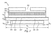
図2は、マニホルド層を備え、合成流体(composite fluid)により冷却される本発明に基づく超小型熱交換器の断面図である。具体的には、図2は、本発明の他の実施形態として、熱源201と、熱接触手段202と、第1の側203’及び第2の側203”を有するスプレッダ領域203と、第2の熱接触手段202’と、超小型領域204と、マニホルド層205とを備える熱交換器200を示している。流体は、インレット/アウトレット206を介して熱交換器200に出入りする。超小型領域204は、インレット/アウトレット206から流体を受け取るように構成され、これにより、超小型領域204に流体が流れる。超小型領域204は、好ましくは、マイクロチャネルを備え、このマイクロチャネルは、好ましくは壁を備え、或いは、微小孔構造又はマイクロピラーを備え、又はマイクロチャネル、微小孔構造及びマイクロピラーの全て又は任意の組合せを備える。好適な超小型領域204のマイクロチャネルは、(熱源の法線方向に)50ミクロン〜2ミリメートルの範囲内の深さと、10〜150マイクロメートルの範囲内の幅とを有する。超小型領域204の壁は、好ましくは、シリコン材料から形成される。この他、マイクロチャネル壁に用いることができる材料としては、炭化シリコン、ダイヤモンド、熱伝導率が25W/m−Kより大きいあらゆる材料、半導体材料又は上述した他の材料がある。
FIG. 2 is a cross-sectional view of a micro heat exchanger according to the present invention comprising a manifold layer and cooled by a composite fluid. Specifically, FIG. 2 shows a
スプレッダ領域203は、第1の側203’と、第2の側203”とを備える。第1の側203’は、熱源201上で熱源201に連結され、第2の側203”は、超小型領域204に連結される。好ましくは、第1の側203’は、第1の熱接触手段202を介して熱源201に連結され、第2の側203”は、第2の熱接触手段202’を介して超小型領域204に連結される。第1及び第2の熱接触手段202、202’は、好ましくは、熱伝導率が高い材料から形成される。スプレッダ領域203及び超小型領域204の結合(第1及び第2の熱接触手段202及び202’によって示している)は、以下に限定されるものではないが、陽極接合、ろう付け、はんだ付け、エポキシによる接着等、様々な手法の何れかを用いて行うことができる。本発明の他の実施形態では、スプレッダ領域203、超小型領域204及び熱源202は、モノリシック構成を有し、モノリシック構造を形成する。
The
スプレッダ領域103のための材料としては、銅が好ましいが、この他、ダイヤモンド、銀、アルミニウム、炭化シリコン又はこれらの組合せ/複合体を用いてもよい。更に、スプレッダ領域203には、シリコンよりより高い熱伝導率(すなわち、200W/m−Kより高い熱伝導率)を有する如何なる材料又は複合材を用いてもよい。
The material for the
マニホルド層205は、好ましくは、超小型領域204に連結された互いに組み合うマニホルド(interwoven manifold)を備える。他の実施形態では、これらの互いに組み合うマニホルドは、単独でスプレッダ領域203に連結され、又は超小型領域204及びスプレッダ領域203の両方に連結される。マニホルド層205は、好ましくは、ガラスから形成される。また、図2に示すマニホルド層205は、本発明の他の実施形態でも用いることができる。他の実施形態において、マニホルド層は、熱交換器に及び熱交換器から流体を流通させるための複数の個別化された孔を備えていてもよい。なお、マニホルド層の詳細及びマニホルド層の様々な実施形態については、引用により本願に援用される、2003年10月6日に出願された、係属中の米国特許出願番号第10/680,584号、発明の名称「発熱デバイスを冷却するための効率的な垂直流体輸送のための方法及び装置(METHOD AND APPARATUS FOR EFFICIENT VERTICAL FLUID DELIVERY FOR COOLING A HEAT PRODUCING DEVICE)」に開示されている。
The
また、本発明は、シリコンを含む超小型領域を形成する工程と、銅を含むスプレッダ領域を形成する工程と、超小型領域をスプレッダ領域に連結する工程とを有する、流体により冷却される超小型熱交換デバイスを製造するための製造方法を開示する。変形例においては、上述のように、超小型領域及びスプレッダ領域は、モノリシック構成であってもよい。好適な実施形態では、精密機械仕上げされた金属から超小型スプレッダ領域を作成する。変形例として、超小型スプレッダ領域は、精密機械仕上げされた合金から作成してもよい。 The present invention also includes a step of forming a micro-region including silicon, a step of forming a spreader region including copper, and a step of connecting the micro-region to the spreader region. A manufacturing method for manufacturing a heat exchange device is disclosed. In a modified example, as described above, the microminiature region and the spreader region may have a monolithic configuration. In a preferred embodiment, the micro spreader region is created from precision machined metal. As a variant, the microspreader region may be made from a precision machined alloy.
更に、流体により冷却される超小型熱交換のためのシステムを開示する。このシステム(図示せず)は、熱源と、熱を拡散させる熱拡散手段と、流体を供給する流体供給手段と、超小型の流体流通のための流体流通手段とを備える。熱拡散手段は、熱源に連結される。超小型の流体流通のための流体流通手段は、流体供給手段から流体を受け取る。超小型の流体流通のための流体流通手段は、好ましくは、マイクロチャネルを備え、マイクロチャネルは、壁を備える。他の実施形態では、マイクロチャネルは、微小孔構造を備え、又はマイクロピラー、若しくは、マイクロチャネル、微小孔構造及びマイクロピラーからなるグループを含む。超小型の流体流通のための流体流通手段は、熱拡散手段に連結される。 Further disclosed is a system for micro heat exchange that is cooled by a fluid. This system (not shown) includes a heat source, a heat diffusion means for diffusing heat, a fluid supply means for supplying a fluid, and a fluid circulation means for circulating a micro fluid. The heat diffusion means is connected to a heat source. A fluid flow means for micro fluid flow receives fluid from the fluid supply means. The fluid flow means for micro fluid flow preferably comprises a microchannel, the microchannel comprising a wall. In other embodiments, the microchannel comprises a microporous structure or comprises a micropillar or a group consisting of a microchannel, a microporous structure and a micropillar. A fluid flow means for flowing a micro fluid is connected to the heat diffusion means.
図3Aは、図2と同様の構造の最上位層に、互いに組み合うマニホルドを有する、合成流体により冷却される超小型熱交換デバイスを備える実施形態のより詳細な図である。具体的には、図3Aは、熱交換器300を示している。熱交換器300は、スプレッダ領域301と、第1のマニホルド層302’と、複数の第1のマニホルド層流路302’と、第2のマニホルド層303と、複数の第2のマニホルド層流路303’と、超小型領域304とを備える。一実施形態においては、熱交換器300サイズは、約18mm×12mm×3mmである。マイクロチャネル領域304の高さは、300ミクロンであり、幅は、50ミクロンであり、ベースは、200ミクロンである。スプレッダ領域301は、300ミクロンの厚さを有し、好ましくは、銅から形成する。熱源(図示せず)の幅は、約0.725ミリメートルである。第1及び第2のマニホルドは、幅が約2ミリメートルであり、長さが10ミリメートルであり、流路の幅は、0.4〜0.8ミリメートルの範囲内である。第1及び第2のマニホルド層を形成するために用いる材料は、ガラスが好ましいが、銅、コバー(Kovar:商標)、及びガラスの何れを用いてもよい。流路302’、303’は、第1及び第2のマニホルド層から最小限の流体を受け取るように構成されたインレット及びアウトレットを備える。なお、これらの寸法は、例示的なものであり、他の寸法の熱源に対しては、他の寸法の熱交換器を用いることができる。
FIG. 3A is a more detailed view of an embodiment comprising a microfluidic heat exchange device cooled by a synthetic fluid with manifolds mating with each other in the top layer of a structure similar to FIG. Specifically, FIG. 3A shows a
図3Bは、モノリシック熱交換器310を示している。熱交換器310は、熱源301と、スプレッダ領域302と、超小型領域303と、第1のマニホルド層304と、第2のマニホルド層305と、トップマニホルド306とを備える。一実施形態においては、超小型領域303からトップマニホルド306の頂部までの高さは、約3ミリメートルであり、超小型領域303から第1及び第2のマニホルド層304、305の頂部までの高さは、約2ミリメートルである。なお、これらの寸法は、例示的なものであり、他の寸法の熱源に対しては、他の寸法の熱交換器を用いることができる。
FIG. 3B shows a
従来の手法に比べ、本発明に基づく、流体により冷却される超小型熱交換器によって、1単位体積あたりの熱輸送面積を最適に拡大することができる。更に、本発明により、低い熱抵抗による周囲への消散熱に加えて、X−Y方向における実質的な温度均一性を実現することができる。本発明の他の利点として、超小型領域及び共にスプレッダ領域を用いて、熱源から発生する熱の横方向の拡散を強めることにより、流体に熱を輸送しやすい高アスペクト比構造を実現でき、これにより、最適な超小型の複合材料流体冷却チャネル式熱交換器を製造することができる。 Compared with the conventional method, the heat transport area per unit volume can be expanded optimally by the micro heat exchanger cooled by the fluid based on the present invention. Further, according to the present invention, substantial temperature uniformity in the XY direction can be realized in addition to the heat dissipated to the surroundings due to the low thermal resistance. As another advantage of the present invention, a high aspect ratio structure that facilitates transport of heat to the fluid can be realized by using the micro-region and the spreader region to enhance the lateral diffusion of heat generated from the heat source. This makes it possible to produce an optimal ultra-compact composite fluid cooling channel heat exchanger.
本発明の構成及び動作原理を明瞭に説明するために、様々な詳細を含む特定の実施例を用いて本発明を説明した。このような特定の実施例の説明及びその詳細は、特許請求の範囲を制限するものではない。本発明の主旨及び範囲から逸脱することなく、例示的に選択された実施例を変更できることは、当業者にとって明らかである。 The invention has been described in terms of specific embodiments, including various details, in order to provide a clear explanation of the structure and operating principles of the invention. Such reference herein to specific embodiments and details thereof is not intended to limit the scope of the claims appended hereto. It will be apparent to those skilled in the art that the exemplary selected embodiments can be modified without departing from the spirit and scope of the present invention.
Claims (109)
a.液体を流すことが可能に構成された超小型領域と、
b.上記熱源側に位置し、該熱源に連結される第1の側と、上記超小型領域に連結される第2の側とを有するスプレッダ領域とを備える熱交換装置。 In an ultra-compact heat exchanger that cools the heat from the heat source with a fluid,
a. An ultra-small area configured to allow liquid to flow;
b. A heat exchange device comprising a spreader region located on the heat source side and having a first side connected to the heat source and a second side connected to the micro region.
請求項1記載の熱交換装置。 The heat exchange apparatus according to claim 1, wherein the fluid is selected from the group consisting of water, ethylene glycol, isopropyl alcohol, ethanol, methanol, and hydrogen peroxide.
a.所定の幅を有する熱源と、
b.液体を流すことが可能に構成され、所定の幅及び厚さを有する超小型領域と、
c.上記熱源に連結される第1の側と、上記超小型領域に連結される第2の側とを有し、所定の幅及び厚さを有するスプレッダ領域とを備える熱交換装置。 In a heat exchange device for micro heat exchange cooled by a fluid,
a. A heat source having a predetermined width;
b. A microscopic region configured to allow liquid to flow and having a predetermined width and thickness;
c. A heat exchanging apparatus comprising a spreader region having a first side connected to the heat source and a second side connected to the microminiature region and having a predetermined width and thickness.
a.シリコンを用いて超小型領域を形成する工程と、
b.銅を用いてスプレッダ領域を形成する工程と、
c.上記超小型領域をスプレッダ領域に連結する工程とを有する熱交換装置の製造方法。 In the manufacturing method of the micro heat exchanger cooled by the fluid,
a. Forming a micro-region using silicon;
b. Forming a spreader region using copper;
c. A method of manufacturing the heat exchange device, comprising the step of coupling the micro-region to the spreader region.
a.所定の幅を有する熱源と、
b.所定の幅を有し、上記熱源に連結され、熱を拡散させる熱拡散手段と、
c.流体を供給する流体供給手段と、
d.上記熱拡散手段に連結され、上記流体供給手段から流体を受け取る、超小型の流体流通のための流体流通手段とを備える熱交換システム。 In a heat exchange system for micro heat exchange cooled by a fluid,
a. A heat source having a predetermined width;
b. A thermal diffusion means having a predetermined width and connected to the heat source for diffusing heat;
c. Fluid supply means for supplying a fluid;
d. A heat exchange system, comprising: a fluid circulation means connected to the heat diffusing means and receiving a fluid from the fluid supply means, for fluidizing the microminiature fluid.
Applications Claiming Priority (4)
| Application Number | Priority Date | Filing Date | Title |
|---|---|---|---|
| US42300902P | 2002-11-01 | 2002-11-01 | |
| US44238303P | 2003-01-24 | 2003-01-24 | |
| US45572903P | 2003-03-17 | 2003-03-17 | |
| PCT/US2003/034755 WO2004042305A2 (en) | 2002-11-01 | 2003-10-30 | Optimal spreader system, device and method for fluid cooled micro-scaled heat exchange |
Publications (2)
| Publication Number | Publication Date |
|---|---|
| JP2006522463A true JP2006522463A (en) | 2006-09-28 |
| JP2006522463A5 JP2006522463A5 (en) | 2006-12-21 |
Family
ID=32314871
Family Applications (2)
| Application Number | Title | Priority Date | Filing Date |
|---|---|---|---|
| JP2005502246A Pending JP2006522463A (en) | 2002-11-01 | 2003-10-30 | Optimal spreader system, apparatus and method for micro heat exchange cooled by fluid |
| JP2005502282A Pending JP2006511787A (en) | 2002-11-01 | 2003-10-31 | Channel flat fin heat exchange system, apparatus and method |
Family Applications After (1)
| Application Number | Title | Priority Date | Filing Date |
|---|---|---|---|
| JP2005502282A Pending JP2006511787A (en) | 2002-11-01 | 2003-10-31 | Channel flat fin heat exchange system, apparatus and method |
Country Status (6)
| Country | Link |
|---|---|
| US (2) | US6988535B2 (en) |
| JP (2) | JP2006522463A (en) |
| AU (2) | AU2003286821A1 (en) |
| DE (2) | DE10393588T5 (en) |
| TW (2) | TWI300466B (en) |
| WO (2) | WO2004042305A2 (en) |
Cited By (3)
| Publication number | Priority date | Publication date | Assignee | Title |
|---|---|---|---|---|
| JP2009239043A (en) * | 2008-03-27 | 2009-10-15 | Furukawa Electric Co Ltd:The | Cooling device equipped with fine channel and method for manufacturing the same |
| JP2015529396A (en) * | 2012-08-22 | 2015-10-05 | フレックス‐エヌ‐ゲート アドバンスト プロダクト ディベロップメント エルエルシー | Microchannel heat sink for LED headlamp |
| KR20200019410A (en) * | 2018-08-14 | 2020-02-24 | 인하대학교 산학협력단 | Composite heat sink and cooling method of heated objects using the same |
Families Citing this family (145)
| Publication number | Priority date | Publication date | Assignee | Title |
|---|---|---|---|---|
| AU2003286821A1 (en) | 2002-11-01 | 2004-06-07 | Cooligy, Inc. | Optimal spreader system, device and method for fluid cooled micro-scaled heat exchange |
| US7836597B2 (en) | 2002-11-01 | 2010-11-23 | Cooligy Inc. | Method of fabricating high surface to volume ratio structures and their integration in microheat exchangers for liquid cooling system |
| US8464781B2 (en) | 2002-11-01 | 2013-06-18 | Cooligy Inc. | Cooling systems incorporating heat exchangers and thermoelectric layers |
| US7591302B1 (en) | 2003-07-23 | 2009-09-22 | Cooligy Inc. | Pump and fan control concepts in a cooling system |
| US7044199B2 (en) * | 2003-10-20 | 2006-05-16 | Thermal Corp. | Porous media cold plate |
| FR2864211B1 (en) * | 2003-12-23 | 2007-01-12 | Christian Muller | THERMAL EXCHANGER HAVING MEANS FOR CONNECTING THERMAL HEATING AND COOLING ELEMENTS |
| US20050263273A1 (en) * | 2004-05-26 | 2005-12-01 | Crumly William R | Electroformed microchannel cooler and methods of making same |
| TWM262755U (en) * | 2004-05-28 | 2005-04-21 | Wen-Chr Liau | Heat sink module for slim electronic equipment |
| US7616444B2 (en) * | 2004-06-04 | 2009-11-10 | Cooligy Inc. | Gimballed attachment for multiple heat exchangers |
| US20050269691A1 (en) * | 2004-06-04 | 2005-12-08 | Cooligy, Inc. | Counter flow micro heat exchanger for optimal performance |
| US7139172B2 (en) * | 2004-07-01 | 2006-11-21 | International Business Machines Corporation | Apparatus and methods for microchannel cooling of semiconductor integrated circuit packages |
| US7234514B2 (en) * | 2004-08-02 | 2007-06-26 | Asml Holding N.V. | Methods and systems for compact, micro-channel laminar heat exchanging |
| US7204298B2 (en) | 2004-11-24 | 2007-04-17 | Lucent Technologies Inc. | Techniques for microchannel cooling |
| US7117931B2 (en) * | 2004-12-31 | 2006-10-10 | Intel Corporation | Systems for low cost liquid cooling |
| US20060157234A1 (en) * | 2005-01-14 | 2006-07-20 | Honeywell International Inc. | Microchannel heat exchanger fabricated by wire electro-discharge machining |
| US20060175042A1 (en) * | 2005-02-08 | 2006-08-10 | Kuo Yung-Pin | Heat dispensing device |
| DE102005014513B4 (en) * | 2005-03-30 | 2011-05-12 | Att Advanced Temperature Test Systems Gmbh | Device and method for tempering a substrate, and method for producing the device |
| US7259965B2 (en) * | 2005-04-07 | 2007-08-21 | Intel Corporation | Integrated circuit coolant microchannel assembly with targeted channel configuration |
| US20060254755A1 (en) * | 2005-05-12 | 2006-11-16 | Win-Haw Chen | Radiation board |
| CA2620353C (en) * | 2005-08-31 | 2013-05-28 | Fmc Corporation | Auto-oxidation production of hydrogen peroxide via oxidation in a microreactor |
| JP2009529479A (en) * | 2005-08-31 | 2009-08-20 | エフ エム シー コーポレーション | Autooxidation of hydrogen peroxide by hydrogenation in a microreactor |
| US20070114010A1 (en) * | 2005-11-09 | 2007-05-24 | Girish Upadhya | Liquid cooling for backlit displays |
| US20070131659A1 (en) * | 2005-12-09 | 2007-06-14 | Durocher Kevin M | Method of making an electronic device cooling system |
| US7342306B2 (en) * | 2005-12-22 | 2008-03-11 | International Business Machines Corporation | High performance reworkable heatsink and packaging structure with solder release layer |
| US7331378B2 (en) * | 2006-01-17 | 2008-02-19 | Delphi Technologies, Inc. | Microchannel heat sink |
| US7913719B2 (en) * | 2006-01-30 | 2011-03-29 | Cooligy Inc. | Tape-wrapped multilayer tubing and methods for making the same |
| US8289710B2 (en) | 2006-02-16 | 2012-10-16 | Liebert Corporation | Liquid cooling systems for server applications |
| CN101438638B (en) | 2006-02-16 | 2015-01-14 | 库利吉公司 | Liquid cooling loops for server applications |
| DE102006008033A1 (en) * | 2006-02-21 | 2007-09-06 | Siemens Ag Österreich | Heat sink with coolant flowing through the pipe |
| US7551439B2 (en) * | 2006-03-28 | 2009-06-23 | Delphi Technologies, Inc. | Fluid cooled electronic assembly |
| JP2009532868A (en) | 2006-03-30 | 2009-09-10 | クーリギー インコーポレイテッド | COOLING DEVICE AND COOLING DEVICE MANUFACTURING METHOD |
| US7715194B2 (en) | 2006-04-11 | 2010-05-11 | Cooligy Inc. | Methodology of cooling multiple heat sources in a personal computer through the use of multiple fluid-based heat exchanging loops coupled via modular bus-type heat exchangers |
| CN100459839C (en) * | 2006-05-10 | 2009-02-04 | 英业达股份有限公司 | Support column with porous structure |
| JP4675283B2 (en) * | 2006-06-14 | 2011-04-20 | トヨタ自動車株式会社 | Heat sink and cooler |
| WO2008024575A2 (en) * | 2006-07-21 | 2008-02-28 | The Curators Of The University Of Missouri | A cryopreservation device and method |
| DE102006045564A1 (en) | 2006-09-25 | 2008-04-03 | Behr Gmbh & Co. Kg | Device for cooling electrical elements |
| DE102006050256A1 (en) * | 2006-10-23 | 2008-04-30 | Pahls, Hans-Helmut, Dipl.-Ing. | Cooler i.e. water cooler, for e.g. electronic component i.e. computer, has chambers and nozzles directly arranged in base plate, where medium flows via chambers and nozzles such that heat energy is carried from core and center of cooler |
| AR065733A1 (en) * | 2007-03-15 | 2009-06-24 | Fmc Corp | RECOVERY OF WATER HYDROGEN PEROXIDE IN THE PRODUCTION OF H2O2 BY SELECTION |
| TW200912621A (en) | 2007-08-07 | 2009-03-16 | Cooligy Inc | Method and apparatus for providing a supplemental cooling to server racks |
| US9453691B2 (en) | 2007-08-09 | 2016-09-27 | Coolit Systems, Inc. | Fluid heat exchange systems |
| US8746330B2 (en) * | 2007-08-09 | 2014-06-10 | Coolit Systems Inc. | Fluid heat exchanger configured to provide a split flow |
| KR100910667B1 (en) * | 2007-10-10 | 2009-08-05 | 한국생산기술연구원 | Method For Making A Water Block For Water Cooling System |
| US7764494B2 (en) * | 2007-11-20 | 2010-07-27 | Basic Electronics, Inc. | Liquid cooled module |
| US8479806B2 (en) * | 2007-11-30 | 2013-07-09 | University Of Hawaii | Two-phase cross-connected micro-channel heat sink |
| US8238098B1 (en) * | 2007-12-10 | 2012-08-07 | Rivas Victor A | Nano machined materials using femtosecond pulse laser technologies to enhanced thermal and optical properties for increased surface area to enhanced heat dissipation and emissivity and electromagnetic radiation |
| US9157687B2 (en) * | 2007-12-28 | 2015-10-13 | Qcip Holdings, Llc | Heat pipes incorporating microchannel heat exchangers |
| US8345424B2 (en) * | 2008-02-19 | 2013-01-01 | Nec Corporation | Optical interconnection device |
| US8250877B2 (en) * | 2008-03-10 | 2012-08-28 | Cooligy Inc. | Device and methodology for the removal of heat from an equipment rack by means of heat exchangers mounted to a door |
| US8604923B1 (en) | 2008-07-16 | 2013-12-10 | Victor Rivas Alvarez | Telemetric health monitoring devices and system |
| WO2010017321A1 (en) * | 2008-08-05 | 2010-02-11 | Cooligy Inc. | Bonded metal and ceramic plates for thermal management of optical and electronic devices |
| US8269341B2 (en) | 2008-11-21 | 2012-09-18 | Infineon Technologies Ag | Cooling structures and methods |
| TWI544865B (en) * | 2009-02-27 | 2016-08-01 | 凱斯系統公司 | Microscale heat transfer systems, add-in cards incorporating same, and related methods |
| TW201036527A (en) * | 2009-03-19 | 2010-10-01 | Acbel Polytech Inc | Large-area liquid-cooled heat-dissipation device |
| US20100314093A1 (en) * | 2009-06-12 | 2010-12-16 | Gamal Refai-Ahmed | Variable heat exchanger |
| US20100326642A1 (en) * | 2009-06-30 | 2010-12-30 | Dino Scorziello | Diamond modified heat exchangers, steam generators, condensers, radiators and feedwater heaters |
| US20100326627A1 (en) * | 2009-06-30 | 2010-12-30 | Schon Steven G | Microelectronics cooling system |
| DE102009054186A1 (en) * | 2009-11-23 | 2011-05-26 | Behr Gmbh & Co. Kg | System for a motor vehicle for heating and / or cooling a battery and a motor vehicle interior |
| JP5714836B2 (en) * | 2010-04-17 | 2015-05-07 | モレックス インコーポレイテドMolex Incorporated | Heat transport unit, electronic board, electronic equipment |
| WO2011149780A1 (en) * | 2010-05-23 | 2011-12-01 | Forced Physics Llc | Heat and energy exchange |
| CN101865620B (en) * | 2010-06-07 | 2011-08-31 | 长春工程学院 | Excitation coupling-type pulsating heat pipe heat exchanger |
| SG187000A1 (en) * | 2010-07-13 | 2013-02-28 | Inertech Ip Llc | Systems and methods for cooling electronic equipment |
| US8077460B1 (en) | 2010-07-19 | 2011-12-13 | Toyota Motor Engineering & Manufacturing North America, Inc. | Heat exchanger fluid distribution manifolds and power electronics modules incorporating the same |
| US8199505B2 (en) | 2010-09-13 | 2012-06-12 | Toyota Motor Engineering & Manufacturing Norh America, Inc. | Jet impingement heat exchanger apparatuses and power electronics modules |
| US8659896B2 (en) | 2010-09-13 | 2014-02-25 | Toyota Motor Engineering & Manufacturing North America, Inc. | Cooling apparatuses and power electronics modules |
| US20120090816A1 (en) * | 2010-10-13 | 2012-04-19 | William Marsh Rice University | Systems and methods for heat transfer utilizing heat exchangers with carbon nanotubes |
| US8797741B2 (en) * | 2010-10-21 | 2014-08-05 | Raytheon Company | Maintaining thermal uniformity in micro-channel cold plates with two-phase flows |
| TWI407072B (en) * | 2010-11-12 | 2013-09-01 | Asia Vital Components Co Ltd | A heat exchanger with shunt structure |
| JP5955775B2 (en) * | 2010-11-18 | 2016-07-20 | 日本碍子株式会社 | Thermal conduction member |
| US9494370B2 (en) * | 2010-12-09 | 2016-11-15 | GeramTec GmbH | Homogeneous liquid cooling of LED array |
| TW201228570A (en) * | 2010-12-17 | 2012-07-01 | Hon Hai Prec Ind Co Ltd | Liquid heat dissipation device |
| US8427832B2 (en) | 2011-01-05 | 2013-04-23 | Toyota Motor Engineering & Manufacturing North America, Inc. | Cold plate assemblies and power electronics modules |
| US8391008B2 (en) | 2011-02-17 | 2013-03-05 | Toyota Motor Engineering & Manufacturing North America, Inc. | Power electronics modules and power electronics module assemblies |
| US8482919B2 (en) | 2011-04-11 | 2013-07-09 | Toyota Motor Engineering & Manufacturing North America, Inc. | Power electronics card assemblies, power electronics modules, and power electronics devices |
| US10365667B2 (en) | 2011-08-11 | 2019-07-30 | Coolit Systems, Inc. | Flow-path controllers and related systems |
| US9279626B2 (en) * | 2012-01-23 | 2016-03-08 | Honeywell International Inc. | Plate-fin heat exchanger with a porous blocker bar |
| US8736048B2 (en) * | 2012-02-16 | 2014-05-27 | International Business Machines Corporation | Flexible heat sink with lateral compliance |
| CN104520663A (en) * | 2012-06-29 | 2015-04-15 | 圣戈本陶瓷及塑料股份有限公司 | Low void fraction thermal storage articles and methods |
| US20140069614A1 (en) * | 2012-09-13 | 2014-03-13 | Asia Vital Components Co., Ltd. | Heat dissipaion device and thermal module using same |
| DE102012217868A1 (en) * | 2012-09-28 | 2014-04-03 | Behr Gmbh & Co. Kg | Heat exchanger |
| US9054361B2 (en) * | 2012-11-20 | 2015-06-09 | GM Global Technology Operations LLC | Utilizing vacuum to pre-compress foam to enable cell insertion during HV battery module assembly |
| CN103017579B (en) * | 2012-12-18 | 2014-10-08 | 中国科学院理化技术研究所 | Plate-fin type heat exchanger with fluid being flowing back and forth in channel |
| US9484283B2 (en) | 2013-01-04 | 2016-11-01 | Toyota Motor Engineering & Manufacturing North America Inc. | Modular jet impingement cooling apparatuses with exchangeable jet plates |
| US8643173B1 (en) | 2013-01-04 | 2014-02-04 | Toyota Motor Engineering & Manufacturing North America, Inc. | Cooling apparatuses and power electronics modules with single-phase and two-phase surface enhancement features |
| US9460985B2 (en) | 2013-01-04 | 2016-10-04 | Toyota Motor Engineering & Manufacturing North America, Inc. | Cooling apparatuses having a jet orifice surface with alternating vapor guide channels |
| TWI531795B (en) | 2013-03-15 | 2016-05-01 | 水冷系統公司 | Sensors, multiplexed communication techniques, and related systems |
| US8981556B2 (en) | 2013-03-19 | 2015-03-17 | Toyota Motor Engineering & Manufacturing North America, Inc. | Jet impingement cooling apparatuses having non-uniform jet orifice sizes |
| JP6277598B2 (en) * | 2013-04-30 | 2018-02-14 | 富士通株式会社 | COOLING MODULE, LAMINATED SEMICONDUCTOR INTEGRATED CIRCUIT DEVICE, AND COOLING MODULE MANUFACTURING METHOD |
| US9247679B2 (en) | 2013-05-24 | 2016-01-26 | Toyota Motor Engineering & Manufacturing North America, Inc. | Jet impingement coolers and power electronics modules comprising the same |
| US9803938B2 (en) | 2013-07-05 | 2017-10-31 | Toyota Motor Engineering & Manufacturing North America, Inc. | Cooling assemblies having porous three dimensional surfaces |
| US9257365B2 (en) | 2013-07-05 | 2016-02-09 | Toyota Motor Engineering & Manufacturing North America, Inc. | Cooling assemblies and power electronics modules having multiple-porosity structures |
| US9131631B2 (en) | 2013-08-08 | 2015-09-08 | Toyota Motor Engineering & Manufacturing North America, Inc. | Jet impingement cooling apparatuses having enhanced heat transfer assemblies |
| CN103594430B (en) * | 2013-10-25 | 2017-01-18 | 上海交通大学 | Micro-channel radiator for dissipating heat of power electronic device |
| CN106102787A (en) * | 2014-01-20 | 2016-11-09 | 哈尔希恩生物医学公司 | The passive separation of whole blood |
| EP2910887B1 (en) | 2014-02-21 | 2019-06-26 | Rolls-Royce Corporation | Microchannel heat exchangers for gas turbine intercooling and condensing as well as corresponding method |
| US20150257249A1 (en) * | 2014-03-08 | 2015-09-10 | Gerald Ho Kim | Heat Sink With Protrusions On Multiple Sides Thereof And Apparatus Using The Same |
| US9437523B2 (en) * | 2014-05-30 | 2016-09-06 | Toyota Motor Engineering & Manufacturing North America, Inc. | Two-sided jet impingement assemblies and power electronics modules comprising the same |
| WO2016093894A1 (en) * | 2014-07-29 | 2016-06-16 | Massachusetts Institute Of Technology | Enhanced flow boiling heat transfer in microchannels with structured surfaces |
| JP6439326B2 (en) | 2014-08-29 | 2018-12-19 | 株式会社Ihi | Reactor |
| US10415597B2 (en) | 2014-10-27 | 2019-09-17 | Coolit Systems, Inc. | Fluid heat exchange systems |
| CN204408824U (en) * | 2014-12-18 | 2015-06-17 | 热流动力能源科技股份有限公司 | Heat-exchange device |
| CN104576573A (en) * | 2014-12-21 | 2015-04-29 | 北京工业大学 | Micro-channel heat exchanger for drop-shaped pin fins |
| US10175005B2 (en) * | 2015-03-30 | 2019-01-08 | Infinera Corporation | Low-cost nano-heat pipe |
| US9978926B2 (en) | 2015-05-14 | 2018-05-22 | The Hong Kong University Of Science And Technology | Thermal radiation microsensor comprising thermoelectric micro pillars |
| CN106288893A (en) * | 2015-06-03 | 2017-01-04 | 丹佛斯微通道换热器(嘉兴)有限公司 | Heat exchanger system |
| US9713284B2 (en) | 2015-07-15 | 2017-07-18 | Hong Kong Applied Science And Technology Research Institute Co. Ltd. | Locally enhanced direct liquid cooling system for high power applications |
| CN105118811B (en) * | 2015-07-27 | 2018-10-23 | 电子科技大学 | A kind of temperature equalization system to be radiated to multi-heat source device using soaking plate and microchannel |
| US10331182B2 (en) * | 2015-07-31 | 2019-06-25 | Hewlett Packard Enterprise Development Lp | Heat exchangers |
| US9622380B1 (en) | 2015-09-30 | 2017-04-11 | Toyota Motor Engineering & Manufacturing North America, Inc. | Two-phase jet impingement cooling devices and electronic device assemblies incorporating the same |
| WO2017059382A1 (en) | 2015-09-30 | 2017-04-06 | Microfabrica Inc. | Micro heat transfer arrays, micro cold plates, and thermal management systems for cooling semiconductor devices, and methods for using and making such arrays, plates, and systems |
| US10727552B2 (en) * | 2015-11-04 | 2020-07-28 | Ford Global Technologies, Llc | Heat exchanger plate for electrified vehicle battery packs |
| US10096537B1 (en) | 2015-12-31 | 2018-10-09 | Microfabrica Inc. | Thermal management systems, methods for making, and methods for using |
| US10085362B2 (en) * | 2016-09-30 | 2018-09-25 | International Business Machines Corporation | Cold plate device for a two-phase cooling system |
| CN106601703B (en) * | 2016-10-27 | 2019-08-02 | 湖北工程学院 | Using the micro-channel heat sink of secondary back refrigerating mode |
| JP6396533B1 (en) * | 2017-04-26 | 2018-09-26 | レノボ・シンガポール・プライベート・リミテッド | Plate-type heat transport device, electronic apparatus, and plate-type heat transport device manufacturing method |
| US10757809B1 (en) | 2017-11-13 | 2020-08-25 | Telephonics Corporation | Air-cooled heat exchanger and thermal arrangement for stacked electronics |
| US20190215987A1 (en) * | 2018-01-11 | 2019-07-11 | Asia Vital Components Co., Ltd. | Water-cooling radiator structure |
| US10921067B2 (en) * | 2018-01-11 | 2021-02-16 | Asia Vital Components Co., Ltd | Water-cooling radiator structure with internal partition member |
| US20190212067A1 (en) * | 2018-01-11 | 2019-07-11 | Asia Vital Components Co., Ltd. | Multi-outlet-inlet multilayered liquid-cooling heat dissipation structure |
| US20190215986A1 (en) * | 2018-01-11 | 2019-07-11 | Asia Vital Components Co., Ltd. | Water-cooling radiator assembly |
| US20190212076A1 (en) * | 2018-01-11 | 2019-07-11 | Asia Vital Components Co., Ltd. | Multi-outlet-inlet liquid-cooling heat dissipation structure |
| US20190214329A1 (en) * | 2018-01-11 | 2019-07-11 | Asia Vital Components Co., Ltd. | Liquid heat dissipation system |
| CN110034082B (en) * | 2018-01-12 | 2021-01-01 | 创意电子股份有限公司 | Electronic device with active heat dissipation |
| US10694640B2 (en) * | 2018-01-30 | 2020-06-23 | Quanta Computer Inc. | Server water cooling modules prevent water leakage device |
| EP3564992B1 (en) | 2018-05-02 | 2021-07-07 | EKWB d.o.o. | Fluid-based cooling device for cooling at least two distinct first heat-generating elements of a heat source assembly |
| CN109103156A (en) * | 2018-08-10 | 2018-12-28 | 桂林电子科技大学 | A kind of fractals microchannel heat sink |
| TWI672471B (en) * | 2018-10-04 | 2019-09-21 | 財團法人金屬工業研究發展中心 | Heat exchanger |
| US11662037B2 (en) | 2019-01-18 | 2023-05-30 | Coolit Systems, Inc. | Fluid flow control valve for fluid flow systems, and methods |
| US11473860B2 (en) | 2019-04-25 | 2022-10-18 | Coolit Systems, Inc. | Cooling module with leak detector and related systems |
| CN113812219A (en) * | 2019-05-21 | 2021-12-17 | 株式会社巴川制纸所 | Temperature control unit |
| SG10201904782SA (en) * | 2019-05-27 | 2020-12-30 | Aem Singapore Pte Ltd | Cold plate and a method of manufacture thereof |
| US11818831B2 (en) | 2019-09-24 | 2023-11-14 | Borgwarner Inc. | Notched baffled heat exchanger for circuit boards |
| US11255610B2 (en) * | 2020-01-22 | 2022-02-22 | Cooler Master Co., Ltd. | Pulse loop heat exchanger and manufacturing method of the same |
| US11149937B2 (en) * | 2020-01-30 | 2021-10-19 | Toyota Motor Engineering & Manufacturing North America, Inc. | Functionally graded manifold microchannel heat sinks |
| CN111479442B (en) * | 2020-03-25 | 2022-03-29 | 中航光电科技股份有限公司 | Array micro-jet and micro-channel composite cold plate |
| US11178789B2 (en) * | 2020-03-31 | 2021-11-16 | Advanced Energy Industries, Inc. | Combination air-water cooling device |
| EP4150216A4 (en) | 2020-05-11 | 2023-11-01 | Coolit Systems, Inc. | Liquid pumping units, and related systems and methods |
| US20210404750A1 (en) * | 2020-06-26 | 2021-12-30 | Vacuum Process Engineering, Inc. | Integrated hybrid compact fluid heat exchanger |
| US11731160B2 (en) * | 2020-07-20 | 2023-08-22 | Rivian Ip Holdings, Llc | Systems and methods for managing sharp transitions for powder coating |
| US20220099389A1 (en) * | 2020-09-25 | 2022-03-31 | Abb Power Electronics Inc. | Systems and methods for thermal management using matrix coldplates |
| AT524235B1 (en) * | 2020-10-09 | 2022-04-15 | Miba Sinter Austria Gmbh | heat transport device |
| US11692776B2 (en) * | 2021-03-02 | 2023-07-04 | Frore Systems Inc. | Mounting and use of piezoelectric cooling systems in devices |
| US11725886B2 (en) | 2021-05-20 | 2023-08-15 | Coolit Systems, Inc. | Modular fluid heat exchange systems |
| CN113651288B (en) * | 2021-07-07 | 2023-10-20 | 北京大学 | Method for preparing micro-channel structure with nano through holes on partition wall |
| US11968803B2 (en) * | 2021-12-22 | 2024-04-23 | Baidu Usa Llc | Two phase immersion system with local fluid accelerations |
| DE102022108277A1 (en) | 2022-04-06 | 2023-10-12 | Semikron Elektronik Gmbh & Co. Kg | Housing, in particular for a power electronic assembly, and arrangement therewith |
Citations (7)
| Publication number | Priority date | Publication date | Assignee | Title |
|---|---|---|---|---|
| JPH04226058A (en) * | 1990-04-27 | 1992-08-14 | Internatl Business Mach Corp <Ibm> | Fluid-cooling hat |
| JPH0769959A (en) * | 1993-08-26 | 1995-03-14 | Kuraray Co Ltd | Production of 2-norbornanone |
| JPH08227956A (en) * | 1994-11-30 | 1996-09-03 | Sumitomo Electric Ind Ltd | Manufacture of substrate |
| JPH08227953A (en) * | 1994-11-30 | 1996-09-03 | Sumitomo Electric Ind Ltd | Substrate and heat sink using it, semiconductor device, element mounting device |
| JPH09129986A (en) * | 1995-09-29 | 1997-05-16 | Siemens Ag | Laser diode device with heat sink and its manufacture |
| JPH1174614A (en) * | 1997-08-28 | 1999-03-16 | Sumitomo Electric Ind Ltd | Thermal dissipation body comprising refrigerant passage and method for manufacturing it |
| JP2002093968A (en) * | 2000-09-11 | 2002-03-29 | Denki Kagaku Kogyo Kk | Module structure |
Family Cites Families (376)
| Publication number | Priority date | Publication date | Assignee | Title |
|---|---|---|---|---|
| US596062A (en) | 1897-12-28 | Device for preventing bursting of freezing pipes | ||
| US627012A (en) * | 1899-06-13 | Fourth to george e | ||
| US2273505A (en) | 1942-02-17 | Container | ||
| US2039593A (en) * | 1935-06-20 | 1936-05-05 | Theodore N Hubbuch | Heat transfer coil |
| US3361195A (en) | 1966-09-23 | 1968-01-02 | Westinghouse Electric Corp | Heat sink member for a semiconductor device |
| US3771219A (en) | 1970-02-05 | 1973-11-13 | Sharp Kk | Method for manufacturing semiconductor device |
| US3654988A (en) | 1970-02-24 | 1972-04-11 | American Standard Inc | Freeze protection for outdoor cooler |
| DE2102254B2 (en) | 1971-01-19 | 1973-05-30 | Robert Bosch Gmbh, 7000 Stuttgart | COOLING DEVICE FOR POWER SEMICONDUCTOR COMPONENTS |
| US3800510A (en) | 1972-05-09 | 1974-04-02 | Celanese Corp | Separating assembly |
| FR2216537B1 (en) | 1973-02-06 | 1975-03-07 | Gaz De France | |
| US3852806A (en) | 1973-05-02 | 1974-12-03 | Gen Electric | Nonwicked heat-pipe cooled power semiconductor device assembly having enhanced evaporated surface heat pipes |
| US3823572A (en) | 1973-08-15 | 1974-07-16 | American Air Filter Co | Freeze protection device in heat pump system |
| US3929154A (en) | 1974-07-29 | 1975-12-30 | Frank E Goodwin | Freeze protection apparatus |
| US3923426A (en) | 1974-08-15 | 1975-12-02 | Alza Corp | Electroosmotic pump and fluid dispenser including same |
| US3904262A (en) | 1974-09-27 | 1975-09-09 | John M Cutchaw | Connector for leadless integrated circuit packages |
| US4072188A (en) | 1975-07-02 | 1978-02-07 | Honeywell Information Systems Inc. | Fluid cooling systems for electronic systems |
| DE2658720C3 (en) | 1976-12-24 | 1982-01-28 | Deutsche Forschungs- und Versuchsanstalt für Luft- und Raumfahrt e.V., 5300 Bonn | Latent heat storage for holding a heat-storing medium |
| US4203448A (en) | 1977-08-19 | 1980-05-20 | Biotronik Mess- Und Therapiegerate Gmbh & Co. | Programmably variable voltage multiplier for implanted stimulator |
| US4312012A (en) | 1977-11-25 | 1982-01-19 | International Business Machines Corp. | Nucleate boiling surface for increasing the heat transfer from a silicon device to a liquid coolant |
| US4203488A (en) | 1978-03-01 | 1980-05-20 | Aavid Engineering, Inc. | Self-fastened heat sinks |
| US4194559A (en) | 1978-11-01 | 1980-03-25 | Thermacore, Inc. | Freeze accommodating heat pipe |
| US4235285A (en) | 1979-10-29 | 1980-11-25 | Aavid Engineering, Inc. | Self-fastened heat sinks |
| US4296455A (en) | 1979-11-23 | 1981-10-20 | International Business Machines Corporation | Slotted heat sinks for high powered air cooled modules |
| US4332291A (en) | 1979-12-21 | 1982-06-01 | D. Mulock-Bentley And Associates (Proprietary) Limited | Heat exchanger with slotted fin strips |
| US4248295A (en) | 1980-01-17 | 1981-02-03 | Thermacore, Inc. | Freezable heat pipe |
| US4345267A (en) | 1980-03-31 | 1982-08-17 | Amp Incorporated | Active device substrate connector having a heat sink |
| US4450472A (en) | 1981-03-02 | 1984-05-22 | The Board Of Trustees Of The Leland Stanford Junior University | Method and means for improved heat removal in compact semiconductor integrated circuits and similar devices utilizing coolant chambers and microscopic channels |
| US4573067A (en) | 1981-03-02 | 1986-02-25 | The Board Of Trustees Of The Leland Stanford Junior University | Method and means for improved heat removal in compact semiconductor integrated circuits |
| US4574876A (en) * | 1981-05-11 | 1986-03-11 | Extracorporeal Medical Specialties, Inc. | Container with tapered walls for heating or cooling fluids |
| US4485429A (en) | 1982-06-09 | 1984-11-27 | Sperry Corporation | Apparatus for cooling integrated circuit chips |
| US4494171A (en) | 1982-08-24 | 1985-01-15 | Sundstrand Corporation | Impingement cooling apparatus for heat liberating device |
| US4516632A (en) | 1982-08-31 | 1985-05-14 | The United States Of America As Represented By The United States Deparment Of Energy | Microchannel crossflow fluid heat exchanger and method for its fabrication |
| US4467861A (en) | 1982-10-04 | 1984-08-28 | Otdel Fiziko-Tekhnicheskikh Problem Energetiki Uralskogo Nauchnogo Tsentra Akademii Nauk Sssr | Heat-transporting device |
| US4474172A (en) | 1982-10-25 | 1984-10-02 | Chevron Research Company | Solar water heating panel |
| JPS59100394A (en) * | 1982-12-01 | 1984-06-09 | M C L:Kk | Heat transfer device |
| GB8323065D0 (en) | 1983-08-26 | 1983-09-28 | Rca Corp | Flux free photo-detector soldering |
| US4567505A (en) | 1983-10-27 | 1986-01-28 | The Board Of Trustees Of The Leland Stanford Junior University | Heat sink and method of attaching heat sink to a semiconductor integrated circuit and the like |
| JPH0673364B2 (en) | 1983-10-28 | 1994-09-14 | 株式会社日立製作所 | Integrated circuit chip cooler |
| US4664181A (en) | 1984-03-05 | 1987-05-12 | Thermo Electron Corporation | Protection of heat pipes from freeze damage |
| US4561040A (en) | 1984-07-12 | 1985-12-24 | Ibm Corporation | Cooling system for VLSI circuit chips |
| US4568431A (en) | 1984-11-13 | 1986-02-04 | Olin Corporation | Process for producing electroplated and/or treated metal foil |
| US4893174A (en) | 1985-07-08 | 1990-01-09 | Hitachi, Ltd. | High density integration of semiconductor circuit |
| ATE64808T1 (en) | 1985-12-13 | 1991-07-15 | Hasler Ag Ascom | METHOD AND DEVICE FOR REMOVAL OF HEAT LOSS OF AT LEAST ONE ASSEMBLY OF ELECTRICAL ELEMENTS. |
| US4716494A (en) | 1986-11-07 | 1987-12-29 | Amp Incorporated | Retention system for removable heat sink |
| US4868712A (en) | 1987-02-04 | 1989-09-19 | Woodman John K | Three dimensional integrated circuit package |
| GB2204181B (en) | 1987-04-27 | 1990-03-21 | Thermalloy Inc | Heat sink apparatus and method of manufacture |
| US4903761A (en) | 1987-06-03 | 1990-02-27 | Lockheed Missiles & Space Company, Inc. | Wick assembly for self-regulated fluid management in a pumped two-phase heat transfer system |
| US5016138A (en) | 1987-10-27 | 1991-05-14 | Woodman John K | Three dimensional integrated circuit package |
| US4894709A (en) | 1988-03-09 | 1990-01-16 | Massachusetts Institute Of Technology | Forced-convection, liquid-cooled, microchannel heat sinks |
| JPH01256775A (en) | 1988-04-04 | 1989-10-13 | Mitsubishi Electric Corp | Pod cooling device |
| US4896719A (en) | 1988-05-11 | 1990-01-30 | Mcdonnell Douglas Corporation | Isothermal panel and plenum |
| US4908112A (en) | 1988-06-16 | 1990-03-13 | E. I. Du Pont De Nemours & Co. | Silicon semiconductor wafer for analyzing micronic biological samples |
| US4884630A (en) | 1988-07-14 | 1989-12-05 | Microelectronics And Computer Technology Corporation | End fed liquid heat exchanger for an electronic component |
| US4866570A (en) | 1988-08-05 | 1989-09-12 | Ncr Corporation | Apparatus and method for cooling an electronic device |
| US4938280A (en) | 1988-11-07 | 1990-07-03 | Clark William E | Liquid-cooled, flat plate heat exchanger |
| CA2002213C (en) | 1988-11-10 | 1999-03-30 | Iwona Turlik | High performance integrated circuit chip package and method of making same |
| US5058627A (en) | 1989-04-10 | 1991-10-22 | Brannen Wiley W | Freeze protection system for water pipes |
| US5145001A (en) | 1989-07-24 | 1992-09-08 | Creare Inc. | High heat flux compact heat exchanger having a permeable heat transfer element |
| US5009760A (en) | 1989-07-28 | 1991-04-23 | Board Of Trustees Of The Leland Stanford Junior University | System for measuring electrokinetic properties and for characterizing electrokinetic separations by monitoring current in electrophoresis |
| CH681168A5 (en) | 1989-11-10 | 1993-01-29 | Westonbridge Int Ltd | Micro-pump for medicinal dosing |
| US4978638A (en) | 1989-12-21 | 1990-12-18 | International Business Machines Corporation | Method for attaching heat sink to plastic packaged electronic component |
| US5083194A (en) | 1990-01-16 | 1992-01-21 | Cray Research, Inc. | Air jet impingement on miniature pin-fin heat sinks for cooling electronic components |
| DE4006152A1 (en) | 1990-02-27 | 1991-08-29 | Fraunhofer Ges Forschung | MICROMINIATURIZED PUMP |
| US5179500A (en) | 1990-02-27 | 1993-01-12 | Grumman Aerospace Corporation | Vapor chamber cooled electronic circuit card |
| US6054034A (en) | 1990-02-28 | 2000-04-25 | Aclara Biosciences, Inc. | Acrylic microchannels and their use in electrophoretic applications |
| US5858188A (en) | 1990-02-28 | 1999-01-12 | Aclara Biosciences, Inc. | Acrylic microchannels and their use in electrophoretic applications |
| US6176962B1 (en) | 1990-02-28 | 2001-01-23 | Aclara Biosciences, Inc. | Methods for fabricating enclosed microchannel structures |
| US5070040A (en) | 1990-03-09 | 1991-12-03 | University Of Colorado Foundation, Inc. | Method and apparatus for semiconductor circuit chip cooling |
| US5016090A (en) * | 1990-03-21 | 1991-05-14 | International Business Machines Corporation | Cross-hatch flow distribution and applications thereof |
| US5096388A (en) | 1990-03-22 | 1992-03-17 | The Charles Stark Draper Laboratory, Inc. | Microfabricated pump |
| US5043797A (en) | 1990-04-03 | 1991-08-27 | General Electric Company | Cooling header connection for a thyristor stack |
| US5265670A (en) * | 1990-04-27 | 1993-11-30 | International Business Machines Corporation | Convection transfer system |
| US5088005A (en) | 1990-05-08 | 1992-02-11 | Sundstrand Corporation | Cold plate for cooling electronics |
| US5161089A (en) | 1990-06-04 | 1992-11-03 | International Business Machines Corporation | Enhanced multichip module cooling with thermally optimized pistons and closely coupled convective cooling channels, and methods of manufacturing the same |
| US5203401A (en) | 1990-06-29 | 1993-04-20 | Digital Equipment Corporation | Wet micro-channel wafer chuck and cooling method |
| US5285347A (en) | 1990-07-02 | 1994-02-08 | Digital Equipment Corporation | Hybird cooling system for electronic components |
| US5057908A (en) | 1990-07-10 | 1991-10-15 | Iowa State University Research Foundation, Inc. | High power semiconductor device with integral heat sink |
| US5420067A (en) | 1990-09-28 | 1995-05-30 | The United States Of America As Represented By The Secretary Of The Navy | Method of fabricatring sub-half-micron trenches and holes |
| US5099910A (en) | 1991-01-15 | 1992-03-31 | Massachusetts Institute Of Technology | Microchannel heat sink with alternating flow directions |
| US5099311A (en) | 1991-01-17 | 1992-03-24 | The United States Of America As Represented By The United States Department Of Energy | Microchannel heat sink assembly |
| JPH06342990A (en) | 1991-02-04 | 1994-12-13 | Internatl Business Mach Corp <Ibm> | Integrated cooling system |
| US5131233A (en) | 1991-03-08 | 1992-07-21 | Cray Computer Corporation | Gas-liquid forced turbulence cooling |
| US5263251A (en) | 1991-04-02 | 1993-11-23 | Microunity Systems Engineering | Method of fabricating a heat exchanger for solid-state electronic devices |
| US5125451A (en) | 1991-04-02 | 1992-06-30 | Microunity Systems Engineering, Inc. | Heat exchanger for solid-state electronic devices |
| US5232047A (en) | 1991-04-02 | 1993-08-03 | Microunity Systems Engineering, Inc. | Heat exchanger for solid-state electronic devices |
| US5294830A (en) * | 1991-05-21 | 1994-03-15 | International Business Machines Corporation | Apparatus for indirect impingement cooling of integrated circuit chips |
| US5199487A (en) | 1991-05-31 | 1993-04-06 | Hughes Aircraft Company | Electroformed high efficiency heat exchanger and method for making |
| US5239200A (en) | 1991-08-21 | 1993-08-24 | International Business Machines Corporation | Apparatus for cooling integrated circuit chips |
| US5228502A (en) | 1991-09-04 | 1993-07-20 | International Business Machines Corporation | Cooling by use of multiple parallel convective surfaces |
| US5386143A (en) | 1991-10-25 | 1995-01-31 | Digital Equipment Corporation | High performance substrate, electronic package and integrated circuit cooling process |
| JPH05217121A (en) | 1991-11-22 | 1993-08-27 | Internatl Business Mach Corp <Ibm> | Method and apparatus for coupling of thermo- sensitive element such as chip provided with magnetic converter, etc. |
| EP0560259B1 (en) | 1992-03-09 | 1996-10-30 | Sumitomo Metal Industries, Ltd. | Heat sink having good heat dissipating characteristics and process for producing the same |
| US5218515A (en) | 1992-03-13 | 1993-06-08 | The United States Of America As Represented By The United States Department Of Energy | Microchannel cooling of face down bonded chips |
| US5239443A (en) | 1992-04-23 | 1993-08-24 | International Business Machines Corporation | Blind hole cold plate cooling system |
| US5317805A (en) | 1992-04-28 | 1994-06-07 | Minnesota Mining And Manufacturing Company | Method of making microchanneled heat exchangers utilizing sacrificial cores |
| US5294834A (en) | 1992-06-01 | 1994-03-15 | Sverdrup Technology, Inc. | Low resistance contacts for shallow junction semiconductors |
| US5247800A (en) | 1992-06-03 | 1993-09-28 | General Electric Company | Thermal connector with an embossed contact for a cryogenic apparatus |
| US5275237A (en) * | 1992-06-12 | 1994-01-04 | Micron Technology, Inc. | Liquid filled hot plate for precise temperature control |
| US5308429A (en) | 1992-09-29 | 1994-05-03 | Digital Equipment Corporation | System for bonding a heatsink to a semiconductor chip package |
| DE4240082C1 (en) | 1992-11-28 | 1994-04-21 | Erno Raumfahrttechnik Gmbh | Heat pipe |
| US5316077A (en) * | 1992-12-09 | 1994-05-31 | Eaton Corporation | Heat sink for electrical circuit components |
| US5520244A (en) * | 1992-12-16 | 1996-05-28 | Sdl, Inc. | Micropost waste heat removal system |
| DE4242841C2 (en) | 1992-12-17 | 1995-05-11 | Litef Gmbh | Method and control device for temperature control for a Peltier-operated temperature control device |
| US5269372A (en) | 1992-12-21 | 1993-12-14 | International Business Machines Corporation | Intersecting flow network for a cold plate cooling system |
| US5397919A (en) | 1993-03-04 | 1995-03-14 | Square Head, Inc. | Heat sink assembly for solid state devices |
| US5299635A (en) | 1993-03-05 | 1994-04-05 | Wynn's Climate Systems, Inc. | Parallel flow condenser baffle |
| US5534328A (en) | 1993-12-02 | 1996-07-09 | E. I. Du Pont De Nemours And Company | Integrated chemical processing apparatus and processes for the preparation thereof |
| JP3477781B2 (en) | 1993-03-23 | 2003-12-10 | セイコーエプソン株式会社 | IC card |
| US5436793A (en) | 1993-03-31 | 1995-07-25 | Ncr Corporation | Apparatus for containing and cooling an integrated circuit device having a thermally insulative positioning member |
| US5459352A (en) | 1993-03-31 | 1995-10-17 | Unisys Corporation | Integrated circuit package having a liquid metal-aluminum/copper joint |
| US5427174A (en) | 1993-04-30 | 1995-06-27 | Heat Transfer Devices, Inc. | Method and apparatus for a self contained heat exchanger |
| US5397019A (en) * | 1993-05-24 | 1995-03-14 | Schmitt; Norman L. | Vending assembly |
| US5380956A (en) | 1993-07-06 | 1995-01-10 | Sun Microsystems, Inc. | Multi-chip cooling module and method |
| US5727618A (en) | 1993-08-23 | 1998-03-17 | Sdl Inc | Modular microchannel heat exchanger |
| US5704416A (en) | 1993-09-10 | 1998-01-06 | Aavid Laboratories, Inc. | Two phase component cooler |
| US5514906A (en) | 1993-11-10 | 1996-05-07 | Fujitsu Limited | Apparatus for cooling semiconductor chips in multichip modules |
| CN1109232C (en) | 1993-12-28 | 2003-05-21 | 昭和电工株式会社 | Plate heat exchanger |
| CH689836A5 (en) | 1994-01-14 | 1999-12-15 | Westonbridge Int Ltd | Micropump. |
| US5383340A (en) | 1994-03-24 | 1995-01-24 | Aavid Laboratories, Inc. | Two-phase cooling system for laptop computers |
| US5544696A (en) | 1994-07-01 | 1996-08-13 | The United States Of America As Represented By The Secretary Of The Air Force | Enhanced nucleate boiling heat transfer for electronic cooling and thermal energy transfer |
| US6129973A (en) | 1994-07-29 | 2000-10-10 | Battelle Memorial Institute | Microchannel laminated mass exchanger and method of making |
| US6126723A (en) | 1994-07-29 | 2000-10-03 | Battelle Memorial Institute | Microcomponent assembly for efficient contacting of fluid |
| US5811062A (en) * | 1994-07-29 | 1998-09-22 | Battelle Memorial Institute | Microcomponent chemical process sheet architecture |
| US5539153A (en) | 1994-08-08 | 1996-07-23 | Hewlett-Packard Company | Method of bumping substrates by contained paste deposition |
| US5526875A (en) | 1994-10-14 | 1996-06-18 | Lin; Shih-Jen | Cooling device for CPU |
| US5641400A (en) | 1994-10-19 | 1997-06-24 | Hewlett-Packard Company | Use of temperature control devices in miniaturized planar column devices and miniaturized total analysis systems |
| US5508234A (en) | 1994-10-31 | 1996-04-16 | International Business Machines Corporation | Microcavity structures, fabrication processes, and applications thereof |
| JP3355824B2 (en) | 1994-11-04 | 2002-12-09 | 株式会社デンソー | Corrugated fin heat exchanger |
| US5585069A (en) | 1994-11-10 | 1996-12-17 | David Sarnoff Research Center, Inc. | Partitioned microelectronic and fluidic device array for clinical diagnostics and chemical synthesis |
| US5785754A (en) | 1994-11-30 | 1998-07-28 | Sumitomo Electric Industries, Ltd. | Substrate, semiconductor device, element-mounted device and preparation of substrate |
| US5876655A (en) | 1995-02-21 | 1999-03-02 | E. I. Du Pont De Nemours And Company | Method for eliminating flow wrinkles in compression molded panels |
| US6227809B1 (en) | 1995-03-09 | 2001-05-08 | University Of Washington | Method for making micropumps |
| DE19514548C1 (en) * | 1995-04-20 | 1996-10-02 | Daimler Benz Ag | Method of manufacturing a micro cooler |
| US5548605A (en) | 1995-05-15 | 1996-08-20 | The Regents Of The University Of California | Monolithic microchannel heatsink |
| US5575929A (en) | 1995-06-05 | 1996-11-19 | The Regents Of The University Of California | Method for making circular tubular channels with two silicon wafers |
| US6057149A (en) | 1995-09-15 | 2000-05-02 | The University Of Michigan | Microscale devices and reactions in microscale devices |
| US5696405A (en) | 1995-10-13 | 1997-12-09 | Lucent Technologies Inc. | Microelectronic package with device cooling |
| JPH09129790A (en) | 1995-11-07 | 1997-05-16 | Toshiba Corp | Heat sink device |
| US5705018A (en) | 1995-12-13 | 1998-01-06 | Hartley; Frank T. | Micromachined peristaltic pump |
| JP3029792B2 (en) | 1995-12-28 | 2000-04-04 | 日本サーボ株式会社 | Multi-phase permanent magnet type rotating electric machine |
| US6039114A (en) | 1996-01-04 | 2000-03-21 | Daimler - Benz Aktiengesellschaft | Cooling body having lugs |
| US6010316A (en) | 1996-01-16 | 2000-01-04 | The Board Of Trustees Of The Leland Stanford Junior University | Acoustic micropump |
| US5579828A (en) | 1996-01-16 | 1996-12-03 | Hudson Products Corporation | Flexible insert for heat pipe freeze protection |
| DE69701857T2 (en) | 1996-02-13 | 2000-12-07 | Abb Ab Vaesteraas | DEVICE FOR POURING INTO A MOLD |
| US5768104A (en) | 1996-02-22 | 1998-06-16 | Cray Research, Inc. | Cooling approach for high power integrated circuits mounted on printed circuit boards |
| US5675473A (en) | 1996-02-23 | 1997-10-07 | Motorola, Inc. | Apparatus and method for shielding an electronic module from electromagnetic radiation |
| US5703536A (en) | 1996-04-08 | 1997-12-30 | Harris Corporation | Liquid cooling system for high power solid state AM transmitter |
| US5885470A (en) | 1997-04-14 | 1999-03-23 | Caliper Technologies Corporation | Controlled fluid transport in microfabricated polymeric substrates |
| JP3716041B2 (en) * | 1996-05-22 | 2005-11-16 | 松下電器産業株式会社 | Absorption heat pump device |
| US5740013A (en) | 1996-07-03 | 1998-04-14 | Hewlett-Packard Company | Electronic device enclosure having electromagnetic energy containment and heat removal characteristics |
| US5800690A (en) | 1996-07-03 | 1998-09-01 | Caliper Technologies Corporation | Variable control of electroosmotic and/or electrophoretic forces within a fluid-containing structure via electrical forces |
| US5801442A (en) | 1996-07-22 | 1998-09-01 | Northrop Grumman Corporation | Microchannel cooling of high power semiconductor devices |
| US5692558A (en) | 1996-07-22 | 1997-12-02 | Northrop Grumman Corporation | Microchannel cooling using aviation fuels for airborne electronics |
| US5763951A (en) | 1996-07-22 | 1998-06-09 | Northrop Grumman Corporation | Non-mechanical magnetic pump for liquid cooling |
| US5731954A (en) | 1996-08-22 | 1998-03-24 | Cheon; Kioan | Cooling system for computer |
| JPH1084139A (en) | 1996-09-09 | 1998-03-31 | Technova:Kk | Thermoelectric conversion device |
| JPH1099592A (en) | 1996-09-27 | 1998-04-21 | Matsushita Electric Ind Co Ltd | Pump of washing machine or the like |
| US5835345A (en) | 1996-10-02 | 1998-11-10 | Sdl, Inc. | Cooler for removing heat from a heated region |
| DE19643717A1 (en) | 1996-10-23 | 1998-04-30 | Asea Brown Boveri | Liquid cooling device for a high-performance semiconductor module |
| US6167948B1 (en) | 1996-11-18 | 2001-01-02 | Novel Concepts, Inc. | Thin, planar heat spreader |
| US5870823A (en) | 1996-11-27 | 1999-02-16 | International Business Machines Corporation | Method of forming a multilayer electronic packaging substrate with integral cooling channels |
| US5964092A (en) | 1996-12-13 | 1999-10-12 | Nippon Sigmax, Co., Ltd. | Electronic cooling apparatus |
| JPH10190071A (en) | 1996-12-20 | 1998-07-21 | Aisin Seiki Co Ltd | Multistage electronic cooling device |
| SE9700205D0 (en) | 1997-01-24 | 1997-01-24 | Peter Lindberg | Integrated microfluidic element |
| JP3450148B2 (en) | 1997-03-07 | 2003-09-22 | 三菱電機株式会社 | Loop type heat pipe |
| DE19710716C2 (en) | 1997-03-14 | 2001-05-10 | Fraunhofer Ges Forschung | Device for cooling electronic components |
| US6391622B1 (en) | 1997-04-04 | 2002-05-21 | Caliper Technologies Corp. | Closed-loop biochemical analyzers |
| US5993750A (en) | 1997-04-11 | 1999-11-30 | Eastman Kodak Company | Integrated ceramic micro-chemical plant |
| US5921087A (en) | 1997-04-22 | 1999-07-13 | Intel Corporation | Method and apparatus for cooling integrated circuits using a thermoelectric module |
| EP0988529B1 (en) | 1997-04-25 | 2013-06-12 | Caliper Life Sciences, Inc. | Microfluidic devices incorporating improved channel geometries |
| US6159353A (en) | 1997-04-30 | 2000-12-12 | Orion Research, Inc. | Capillary electrophoretic separation system |
| US5880524A (en) | 1997-05-05 | 1999-03-09 | Intel Corporation | Heat pipe lid for electronic packages |
| JP2002512737A (en) | 1997-05-08 | 2002-04-23 | ナノシステムズ,インコーポレイテッド | Silicon etching method for manufacturing microchannel plate |
| US6090251A (en) | 1997-06-06 | 2000-07-18 | Caliper Technologies, Inc. | Microfabricated structures for facilitating fluid introduction into microfluidic devices |
| US5869004A (en) | 1997-06-09 | 1999-02-09 | Caliper Technologies Corp. | Methods and apparatus for in situ concentration and/or dilution of materials in microfluidic systems |
| US5901037A (en) | 1997-06-18 | 1999-05-04 | Northrop Grumman Corporation | Closed loop liquid cooling for semiconductor RF amplifier modules |
| US5942093A (en) | 1997-06-18 | 1999-08-24 | Sandia Corporation | Electro-osmotically driven liquid delivery method and apparatus |
| US6019882A (en) | 1997-06-25 | 2000-02-01 | Sandia Corporation | Electrokinetic high pressure hydraulic system |
| US6013164A (en) | 1997-06-25 | 2000-01-11 | Sandia Corporation | Electokinetic high pressure hydraulic system |
| US6277257B1 (en) | 1997-06-25 | 2001-08-21 | Sandia Corporation | Electrokinetic high pressure hydraulic system |
| US6001231A (en) | 1997-07-15 | 1999-12-14 | Caliper Technologies Corp. | Methods and systems for monitoring and controlling fluid flow rates in microfluidic systems |
| US6034872A (en) | 1997-07-16 | 2000-03-07 | International Business Machines Corporation | Cooling computer systems |
| US6907921B2 (en) | 1998-06-18 | 2005-06-21 | 3M Innovative Properties Company | Microchanneled active fluid heat exchanger |
| US6400012B1 (en) | 1997-09-17 | 2002-06-04 | Advanced Energy Voorhees, Inc. | Heat sink for use in cooling an integrated circuit |
| US5909057A (en) * | 1997-09-23 | 1999-06-01 | Lsi Logic Corporation | Integrated heat spreader/stiffener with apertures for semiconductor package |
| US6012902A (en) | 1997-09-25 | 2000-01-11 | Caliper Technologies Corp. | Micropump |
| US5842787A (en) | 1997-10-09 | 1998-12-01 | Caliper Technologies Corporation | Microfluidic systems incorporating varied channel dimensions |
| US5836750A (en) | 1997-10-09 | 1998-11-17 | Honeywell Inc. | Electrostatically actuated mesopump having a plurality of elementary cells |
| US5945217A (en) | 1997-10-14 | 1999-08-31 | Gore Enterprise Holdings, Inc. | Thermally conductive polytrafluoroethylene article |
| US5829514A (en) | 1997-10-29 | 1998-11-03 | Eastman Kodak Company | Bonded cast, pin-finned heat sink and method of manufacture |
| US6174675B1 (en) | 1997-11-25 | 2001-01-16 | Caliper Technologies Corp. | Electrical current for controlling fluid parameters in microchannels |
| US5893726A (en) * | 1997-12-15 | 1999-04-13 | Micron Technology, Inc. | Semiconductor package with pre-fabricated cover and method of fabrication |
| US6140860A (en) | 1997-12-31 | 2000-10-31 | Intel Corporation | Thermal sensing circuit |
| US6167910B1 (en) | 1998-01-20 | 2001-01-02 | Caliper Technologies Corp. | Multi-layer microfluidic devices |
| US6100541A (en) | 1998-02-24 | 2000-08-08 | Caliper Technologies Corporation | Microfluidic devices and systems incorporating integrated optical elements |
| US6084178A (en) | 1998-02-27 | 2000-07-04 | Hewlett-Packard Company | Perimeter clamp for mounting and aligning a semiconductor component as part of a field replaceable unit (FRU) |
| US6019165A (en) | 1998-05-18 | 2000-02-01 | Batchelder; John Samuel | Heat exchange apparatus |
| JP3858484B2 (en) * | 1998-11-24 | 2006-12-13 | 松下電器産業株式会社 | Laminate heat exchanger |
| US6227287B1 (en) | 1998-05-25 | 2001-05-08 | Denso Corporation | Cooling apparatus by boiling and cooling refrigerant |
| KR100266698B1 (en) | 1998-06-12 | 2000-09-15 | 김영환 | Semiconductor chip package and fabrication method thereof |
| US6196307B1 (en) | 1998-06-17 | 2001-03-06 | Intersil Americas Inc. | High performance heat exchanger and method |
| US5940270A (en) | 1998-07-08 | 1999-08-17 | Puckett; John Christopher | Two-phase constant-pressure closed-loop water cooling system for a heat producing device |
| JP2000031362A (en) * | 1998-07-13 | 2000-01-28 | Denso Corp | Cooler by boiling and condensing coolant |
| US5965813A (en) | 1998-07-23 | 1999-10-12 | Industry Technology Research Institute | Integrated flow sensor |
| US6129260A (en) | 1998-08-19 | 2000-10-10 | Fravillig Technologies Company | Solderable structures |
| JP2000077586A (en) * | 1998-08-28 | 2000-03-14 | Fuji Electric Co Ltd | Boiling cooler |
| US6119729A (en) | 1998-09-14 | 2000-09-19 | Arise Technologies Corporation | Freeze protection apparatus for fluid transport passages |
| US6146103A (en) | 1998-10-09 | 2000-11-14 | The Regents Of The University Of California | Micromachined magnetohydrodynamic actuators and sensors |
| US6021045A (en) | 1998-10-26 | 2000-02-01 | Chip Coolers, Inc. | Heat sink assembly with threaded collar and multiple pressure capability |
| US6032689A (en) | 1998-10-30 | 2000-03-07 | Industrial Technology Research Institute | Integrated flow controller module |
| JP3395164B2 (en) * | 1998-11-05 | 2003-04-07 | インターナショナル・ビジネス・マシーンズ・コーポレーション | Semiconductor device |
| US6086330A (en) | 1998-12-21 | 2000-07-11 | Motorola, Inc. | Low-noise, high-performance fan |
| US6313992B1 (en) | 1998-12-22 | 2001-11-06 | James J. Hildebrandt | Method and apparatus for increasing the power density of integrated circuit boards and their components |
| US6365962B1 (en) | 2000-03-29 | 2002-04-02 | Intel Corporation | Flip-chip on flex for high performance packaging applications |
| US6416642B1 (en) | 1999-01-21 | 2002-07-09 | Caliper Technologies Corp. | Method and apparatus for continuous liquid flow in microscale channels using pressure injection, wicking, and electrokinetic injection |
| AU3372800A (en) | 1999-02-23 | 2000-09-14 | Caliper Technologies Corporation | Manipulation of microparticles in microfluidic systems |
| US6553253B1 (en) | 1999-03-12 | 2003-04-22 | Biophoretic Therapeutic Systems, Llc | Method and system for electrokinetic delivery of a substance |
| US6406605B1 (en) | 1999-06-01 | 2002-06-18 | Ysi Incorporated | Electroosmotic flow controlled microfluidic devices |
| US6287440B1 (en) | 1999-06-18 | 2001-09-11 | Sandia Corporation | Method for eliminating gas blocking in electrokinetic pumping systems |
| US6495015B1 (en) | 1999-06-18 | 2002-12-17 | Sandia National Corporation | Electrokinetically pumped high pressure sprays |
| US6096656A (en) | 1999-06-24 | 2000-08-01 | Sandia Corporation | Formation of microchannels from low-temperature plasma-deposited silicon oxynitride |
| US6234240B1 (en) | 1999-07-01 | 2001-05-22 | Kioan Cheon | Fanless cooling system for computer |
| US6131650A (en) | 1999-07-20 | 2000-10-17 | Thermal Corp. | Fluid cooled single phase heat sink |
| US6396706B1 (en) | 1999-07-30 | 2002-05-28 | Credence Systems Corporation | Self-heating circuit board |
| US6457515B1 (en) | 1999-08-06 | 2002-10-01 | The Ohio State University | Two-layered micro channel heat sink, devices and systems incorporating same |
| JP3518434B2 (en) | 1999-08-11 | 2004-04-12 | 株式会社日立製作所 | Multi-chip module cooling system |
| US6693320B1 (en) | 1999-08-30 | 2004-02-17 | Micron Technology, Inc. | Capacitor structures with recessed hemispherical grain silicon |
| US6360814B1 (en) | 1999-08-31 | 2002-03-26 | Denso Corporation | Cooling device boiling and condensing refrigerant |
| US6293333B1 (en) | 1999-09-02 | 2001-09-25 | The United States Of America As Represented By The Secretary Of The Air Force | Micro channel heat pipe having wire cloth wick and method of fabrication |
| US6216343B1 (en) | 1999-09-02 | 2001-04-17 | The United States Of America As Represented By The Secretary Of The Air Force | Method of making micro channel heat pipe having corrugated fin elements |
| US6210986B1 (en) | 1999-09-23 | 2001-04-03 | Sandia Corporation | Microfluidic channel fabrication method |
| JP2001110956A (en) | 1999-10-04 | 2001-04-20 | Matsushita Electric Ind Co Ltd | Cooling equipment for electronic component |
| AUPQ332199A0 (en) | 1999-10-07 | 1999-11-04 | Hydrocool Pty Limited | Heat exchanger for an electronic heat pump |
| KR100338810B1 (en) | 1999-11-08 | 2002-05-31 | 윤종용 | cooling device |
| US6166907A (en) | 1999-11-26 | 2000-12-26 | Chien; Chuan-Fu | CPU cooling system |
| US6729383B1 (en) | 1999-12-16 | 2004-05-04 | The United States Of America As Represented By The Secretary Of The Navy | Fluid-cooled heat sink with turbulence-enhancing support pins |
| US6324075B1 (en) | 1999-12-20 | 2001-11-27 | Intel Corporation | Partially covered motherboard with EMI partition gateway |
| JP2001185306A (en) | 1999-12-28 | 2001-07-06 | Jst Mfg Co Ltd | Connector for module |
| US6154363A (en) | 1999-12-29 | 2000-11-28 | Chang; Neng Chao | Electronic device cooling arrangement |
| US6272012B1 (en) | 2000-02-03 | 2001-08-07 | Crystal Group Inc. | System and method for cooling compact PCI circuit cards in a computer |
| US6415860B1 (en) | 2000-02-09 | 2002-07-09 | Board Of Supervisors Of Louisiana State University And Agricultural And Mechanical College | Crossflow micro heat exchanger |
| JP2001223309A (en) * | 2000-02-09 | 2001-08-17 | Fujine Sangyo:Kk | Sealing-type plate heat movable body |
| US6337794B1 (en) | 2000-02-11 | 2002-01-08 | International Business Machines Corporation | Isothermal heat sink with tiered cooling channels |
| US6301109B1 (en) | 2000-02-11 | 2001-10-09 | International Business Machines Corporation | Isothermal heat sink with cross-flow openings between channels |
| US6253835B1 (en) | 2000-02-11 | 2001-07-03 | International Business Machines Corporation | Isothermal heat sink with converging, diverging channels |
| EP1123739B1 (en) | 2000-02-11 | 2006-11-29 | STMicroelectronics S.r.l. | Integrated device for microfluid thermoregulation, and manufacturing process thereof |
| US6417060B2 (en) | 2000-02-25 | 2002-07-09 | Borealis Technical Limited | Method for making a diode device |
| US6761211B2 (en) | 2000-03-14 | 2004-07-13 | Delphi Technologies, Inc. | High-performance heat sink for electronics cooling |
| US6257320B1 (en) | 2000-03-28 | 2001-07-10 | Alec Wargo | Heat sink device for power semiconductors |
| US6347036B1 (en) | 2000-03-29 | 2002-02-12 | Dell Products L.P. | Apparatus and method for mounting a heat generating component in a computer system |
| US6366467B1 (en) | 2000-03-31 | 2002-04-02 | Intel Corporation | Dual-socket interposer and method of fabrication therefor |
| US6290909B1 (en) | 2000-04-13 | 2001-09-18 | Sandia Corporation | Sample injector for high pressure liquid chromatography |
| EP1148772B1 (en) | 2000-04-19 | 2009-12-23 | Thermal Form & Function Inc. | Cold plate utilizing fin with evaporating refrigerant |
| JP2001326311A (en) | 2000-05-15 | 2001-11-22 | Hitachi Ltd | Cooling device for electronic equipment |
| FR2809281B1 (en) | 2000-05-22 | 2002-07-12 | Alstom | ELECTRONIC POWER DEVICE |
| US6787052B1 (en) | 2000-06-19 | 2004-09-07 | Vladimir Vaganov | Method for fabricating microstructures with deep anisotropic etching of thick silicon wafers |
| US20020031947A1 (en) * | 2000-07-17 | 2002-03-14 | Gundermann James Edward | Electrical connector module and electrical connector assembly including same |
| US6366462B1 (en) * | 2000-07-18 | 2002-04-02 | International Business Machines Corporation | Electronic module with integral refrigerant evaporator assembly and control system therefore |
| US6459582B1 (en) | 2000-07-19 | 2002-10-01 | Fujitsu Limited | Heatsink apparatus for de-coupling clamping forces on an integrated circuit package |
| US6317326B1 (en) | 2000-09-14 | 2001-11-13 | Sun Microsystems, Inc. | Integrated circuit device package and heat dissipation device |
| US6915648B2 (en) | 2000-09-14 | 2005-07-12 | Xdx Inc. | Vapor compression systems, expansion devices, flow-regulating members, and vehicles, and methods for using vapor compression systems |
| US6388317B1 (en) | 2000-09-25 | 2002-05-14 | Lockheed Martin Corporation | Solid-state chip cooling by use of microchannel coolant flow |
| JP2002110878A (en) * | 2000-09-28 | 2002-04-12 | Matsushita Refrig Co Ltd | Cooling module and cooling system comprising it |
| US6469893B1 (en) | 2000-09-29 | 2002-10-22 | Intel Corporation | Direct heatpipe attachment to die using center point loading |
| US6324058B1 (en) | 2000-10-25 | 2001-11-27 | Chieh-Jen Hsiao | Heat-dissipating apparatus for an integrated circuit device |
| US6537437B1 (en) | 2000-11-13 | 2003-03-25 | Sandia Corporation | Surface-micromachined microfluidic devices |
| US6367544B1 (en) | 2000-11-21 | 2002-04-09 | Thermal Corp. | Thermal jacket for reducing condensation and method for making same |
| US6478258B1 (en) | 2000-11-21 | 2002-11-12 | Space Systems/Loral, Inc. | Spacecraft multiple loop heat pipe thermal system for internal equipment panel applications |
| US6578626B1 (en) | 2000-11-21 | 2003-06-17 | Thermal Corp. | Liquid cooled heat exchanger with enhanced flow |
| US6336497B1 (en) | 2000-11-24 | 2002-01-08 | Ching-Bin Lin | Self-recirculated heat dissipating means for cooling central processing unit |
| US6437981B1 (en) * | 2000-11-30 | 2002-08-20 | Harris Corporation | Thermally enhanced microcircuit package and method of forming same |
| US6367543B1 (en) | 2000-12-11 | 2002-04-09 | Thermal Corp. | Liquid-cooled heat sink with thermal jacket |
| US6459581B1 (en) | 2000-12-19 | 2002-10-01 | Harris Corporation | Electronic device using evaporative micro-cooling and associated methods |
| JP2002188876A (en) | 2000-12-20 | 2002-07-05 | Hitachi Ltd | Liquid cooling system and personal computer provided with the system |
| US6698924B2 (en) | 2000-12-21 | 2004-03-02 | Tank, Inc. | Cooling system comprising a circular venturi |
| CA2329408C (en) * | 2000-12-21 | 2007-12-04 | Long Manufacturing Ltd. | Finned plate heat exchanger |
| US6431260B1 (en) | 2000-12-21 | 2002-08-13 | International Business Machines Corporation | Cavity plate and jet nozzle assemblies for use in cooling an electronic module, and methods of fabrication thereof |
| JP2002280508A (en) * | 2001-01-11 | 2002-09-27 | Matsushita Refrig Co Ltd | Cooling module and cooling system using the cooling module |
| US6466442B2 (en) | 2001-01-29 | 2002-10-15 | Ching-Bin Lin | Guidably-recirculated heat dissipating means for cooling central processing unit |
| US6484521B2 (en) | 2001-02-22 | 2002-11-26 | Hewlett-Packard Company | Spray cooling with local control of nozzles |
| CN1290392C (en) | 2001-03-02 | 2006-12-13 | 三洋电机株式会社 | Electronic device |
| US6424531B1 (en) | 2001-03-13 | 2002-07-23 | Delphi Technologies, Inc. | High performance heat sink for electronics cooling |
| US20020134543A1 (en) | 2001-03-20 | 2002-09-26 | Motorola, Inc | Connecting device with local heating element and method for using same |
| US6601643B2 (en) | 2001-04-27 | 2003-08-05 | Samsung Electronics Co., Ltd | Flat evaporator |
| US6682844B2 (en) | 2001-04-27 | 2004-01-27 | Plug Power Inc. | Release valve and method for venting a system |
| US6609560B2 (en) | 2001-04-28 | 2003-08-26 | Samsung Electronics Co., Ltd. | Flat evaporator |
| US6600220B2 (en) | 2001-05-14 | 2003-07-29 | Hewlett-Packard Company | Power distribution in multi-chip modules |
| US6651735B2 (en) | 2001-05-15 | 2003-11-25 | Samsung Electronics Co., Ltd. | Evaporator of CPL cooling apparatus having fine wick structure |
| US7462852B2 (en) | 2001-12-17 | 2008-12-09 | Tecomet, Inc. | Devices, methods, and systems involving cast collimators |
| US6449162B1 (en) | 2001-06-07 | 2002-09-10 | International Business Machines Corporation | Removable land grid array cooling solution |
| US6796372B2 (en) | 2001-06-12 | 2004-09-28 | Liebert Corporation | Single or dual buss thermal transfer system |
| US6657121B2 (en) | 2001-06-27 | 2003-12-02 | Thermal Corp. | Thermal management system and method for electronics system |
| US6519151B2 (en) * | 2001-06-27 | 2003-02-11 | International Business Machines Corporation | Conic-sectioned plate and jet nozzle assembly for use in cooling an electronic module, and methods of fabrication thereof |
| US6536510B2 (en) | 2001-07-10 | 2003-03-25 | Thermal Corp. | Thermal bus for cabinets housing high power electronics equipment |
| US6385044B1 (en) | 2001-07-27 | 2002-05-07 | International Business Machines Corporation | Heat pipe heat sink assembly for cooling semiconductor chips |
| US6587343B2 (en) | 2001-08-29 | 2003-07-01 | Sun Microsystems, Inc. | Water-cooled system and method for cooling electronic components |
| US6438984B1 (en) | 2001-08-29 | 2002-08-27 | Sun Microsystems, Inc. | Refrigerant-cooled system and method for cooling electronic components |
| US6533029B1 (en) | 2001-09-04 | 2003-03-18 | Thermal Corp. | Non-inverted meniscus loop heat pipe/capillary pumped loop evaporator |
| JP3636118B2 (en) | 2001-09-04 | 2005-04-06 | 株式会社日立製作所 | Water cooling device for electronic equipment |
| US6981543B2 (en) | 2001-09-20 | 2006-01-03 | Intel Corporation | Modular capillary pumped loop cooling system |
| TW516810U (en) | 2001-09-27 | 2003-01-01 | Hoya Tech Co Ltd | Fastening device for heat sink |
| US6942018B2 (en) | 2001-09-28 | 2005-09-13 | The Board Of Trustees Of The Leland Stanford Junior University | Electroosmotic microchannel cooling system |
| US6449157B1 (en) | 2001-10-03 | 2002-09-10 | Ho Kang Chu | IC package assembly with retention mechanism |
| US6581388B2 (en) | 2001-11-27 | 2003-06-24 | Sun Microsystems, Inc. | Active temperature gradient reducer |
| US6527835B1 (en) * | 2001-12-21 | 2003-03-04 | Sandia Corporation | Chemical preconcentrator with integral thermal flow sensor |
| US6477045B1 (en) | 2001-12-28 | 2002-11-05 | Tien-Lai Wang | Heat dissipater for a central processing unit |
| US6643132B2 (en) | 2002-01-04 | 2003-11-04 | Intel Corporation | Chassis-level thermal interface component for transfer of heat from an electronic component of a computer system |
| US6700785B2 (en) | 2002-01-04 | 2004-03-02 | Intel Corporation | Computer system which locks a server unit subassembly in a selected position in a support frame |
| US6679315B2 (en) | 2002-01-14 | 2004-01-20 | Marconi Communications, Inc. | Small scale chip cooler assembly |
| US6606251B1 (en) | 2002-02-07 | 2003-08-12 | Cooligy Inc. | Power conditioning module |
| CN1639532A (en) | 2002-02-26 | 2005-07-13 | 麦克罗斯制造公司 | Capillary evaporator |
| US6591625B1 (en) | 2002-04-17 | 2003-07-15 | Agilent Technologies, Inc. | Cooling of substrate-supported heat-generating components |
| TWI234063B (en) | 2002-05-15 | 2005-06-11 | Matsushita Electric Ind Co Ltd | Cooling apparatus for electronic equipment |
| US7209355B2 (en) | 2002-05-15 | 2007-04-24 | Matsushita Electric Industrial Co., Ltd. | Cooling device and an electronic apparatus including the same |
| US6827128B2 (en) | 2002-05-20 | 2004-12-07 | The Board Of Trustees Of The University Of Illinois | Flexible microchannel heat exchanger |
| US6988534B2 (en) | 2002-11-01 | 2006-01-24 | Cooligy, Inc. | Method and apparatus for flexible fluid delivery for cooling desired hot spots in a heat producing device |
| US20040008483A1 (en) | 2002-07-13 | 2004-01-15 | Kioan Cheon | Water cooling type cooling system for electronic device |
| US6588498B1 (en) | 2002-07-18 | 2003-07-08 | Delphi Technologies, Inc. | Thermosiphon for electronics cooling with high performance boiling and condensing surfaces |
| US20040020225A1 (en) | 2002-08-02 | 2004-02-05 | Patel Chandrakant D. | Cooling system |
| US6836131B2 (en) | 2002-08-16 | 2004-12-28 | Credence Systems Corp. | Spray cooling and transparent cooling plate thermal management system |
| JP3641258B2 (en) | 2002-08-26 | 2005-04-20 | 株式会社東芝 | Electronics |
| TW578992U (en) | 2002-09-09 | 2004-03-01 | Hon Hai Prec Ind Co Ltd | Heat sink assembly |
| US6714412B1 (en) | 2002-09-13 | 2004-03-30 | International Business Machines Corporation | Scalable coolant conditioning unit with integral plate heat exchanger/expansion tank and method of use |
| DE10243026B3 (en) | 2002-09-13 | 2004-06-03 | Oliver Laing | Device for local cooling or heating of an object |
| US6894899B2 (en) | 2002-09-13 | 2005-05-17 | Hong Kong Cheung Tat Electrical Co. Ltd. | Integrated fluid cooling system for electronic components |
| DE10242776B4 (en) * | 2002-09-14 | 2013-05-23 | Alstom Technology Ltd. | Method for operating an emission control system |
| US20040052052A1 (en) | 2002-09-18 | 2004-03-18 | Rivera Rudy A. | Circuit cooling apparatus |
| AU2003270882A1 (en) | 2002-09-23 | 2004-05-04 | Cooligy, Inc. | Micro-fabricated electrokinetic pump with on-frit electrode |
| US6881039B2 (en) | 2002-09-23 | 2005-04-19 | Cooligy, Inc. | Micro-fabricated electrokinetic pump |
| US6807056B2 (en) | 2002-09-24 | 2004-10-19 | Hitachi, Ltd. | Electronic equipment |
| US6994151B2 (en) | 2002-10-22 | 2006-02-07 | Cooligy, Inc. | Vapor escape microchannel heat exchanger |
| US6829142B2 (en) | 2002-10-25 | 2004-12-07 | Hewlett-Packard Development Company, L.P. | Cell thermal connector |
| US20040112571A1 (en) | 2002-11-01 | 2004-06-17 | Cooligy, Inc. | Method and apparatus for efficient vertical fluid delivery for cooling a heat producing device |
| US7000684B2 (en) | 2002-11-01 | 2006-02-21 | Cooligy, Inc. | Method and apparatus for efficient vertical fluid delivery for cooling a heat producing device |
| AU2003286821A1 (en) | 2002-11-01 | 2004-06-07 | Cooligy, Inc. | Optimal spreader system, device and method for fluid cooled micro-scaled heat exchange |
| US6986382B2 (en) | 2002-11-01 | 2006-01-17 | Cooligy Inc. | Interwoven manifolds for pressure drop reduction in microchannel heat exchangers |
| AU2003286855A1 (en) | 2002-11-01 | 2004-06-07 | Cooligy, Inc. | Method and apparatus for achieving temperature uniformity and hot spot cooling in a heat producing device |
| US20060060333A1 (en) | 2002-11-05 | 2006-03-23 | Lalit Chordia | Methods and apparatuses for electronics cooling |
| US6889515B2 (en) | 2002-11-12 | 2005-05-10 | Isothermal Systems Research, Inc. | Spray cooling system |
| US7210227B2 (en) | 2002-11-26 | 2007-05-01 | Intel Corporation | Decreasing thermal contact resistance at a material interface |
| US6809928B2 (en) | 2002-12-27 | 2004-10-26 | Intel Corporation | Sealed and pressurized liquid cooling system for microprocessor |
| KR20040065626A (en) | 2003-01-15 | 2004-07-23 | 엘지전자 주식회사 | Heat exchanger |
| US7201012B2 (en) | 2003-01-31 | 2007-04-10 | Cooligy, Inc. | Remedies to prevent cracking in a liquid system |
| US7044196B2 (en) | 2003-01-31 | 2006-05-16 | Cooligy,Inc | Decoupled spring-loaded mounting apparatus and method of manufacturing thereof |
| US7293423B2 (en) | 2004-06-04 | 2007-11-13 | Cooligy Inc. | Method and apparatus for controlling freezing nucleation and propagation |
| US7090001B2 (en) | 2003-01-31 | 2006-08-15 | Cooligy, Inc. | Optimized multiple heat pipe blocks for electronics cooling |
| US6798660B2 (en) | 2003-02-13 | 2004-09-28 | Dell Products L.P. | Liquid cooling module |
| JP4199018B2 (en) | 2003-02-14 | 2008-12-17 | 株式会社日立製作所 | Rack mount server system |
| US7017654B2 (en) | 2003-03-17 | 2006-03-28 | Cooligy, Inc. | Apparatus and method of forming channels in a heat-exchanging device |
| US6992891B2 (en) | 2003-04-02 | 2006-01-31 | Intel Corporation | Metal ball attachment of heat dissipation devices |
| US7337832B2 (en) | 2003-04-30 | 2008-03-04 | Valeo, Inc. | Heat exchanger |
| US6763880B1 (en) | 2003-06-26 | 2004-07-20 | Evserv Tech Corporation | Liquid cooled radiation module for servers |
| US7483261B2 (en) | 2003-06-27 | 2009-01-27 | Nec Corporation | Cooling device for an electronic equipment |
| US7021369B2 (en) | 2003-07-23 | 2006-04-04 | Cooligy, Inc. | Hermetic closed loop fluid system |
| JP2005064186A (en) | 2003-08-11 | 2005-03-10 | Hitachi Ltd | Electronic apparatus equipped with cooling system |
| US7508672B2 (en) | 2003-09-10 | 2009-03-24 | Qnx Cooling Systems Inc. | Cooling system |
| JP4157451B2 (en) | 2003-09-30 | 2008-10-01 | 株式会社東芝 | Gas-liquid separation mechanism, reserve tank, and electronic equipment |
| TWM248227U (en) | 2003-10-17 | 2004-10-21 | Hon Hai Prec Ind Co Ltd | Liquid cooling apparatus |
| US7273088B2 (en) | 2003-12-17 | 2007-09-25 | Hewlett-Packard Development Company, L.P. | One or more heat exchanger components in major part operably locatable outside computer chassis |
| US7009842B2 (en) | 2004-01-30 | 2006-03-07 | Isothermal Systems Research, Inc. | Three dimensional packaging and cooling of mixed signal, mixed power density electronic modules |
| US7021012B2 (en) | 2004-02-04 | 2006-04-04 | Karl Zeng | Watertight decking |
| US20050257532A1 (en) | 2004-03-11 | 2005-11-24 | Masami Ikeda | Module for cooling semiconductor device |
| US7011143B2 (en) | 2004-05-04 | 2006-03-14 | International Business Machines Corporation | Method and apparatus for cooling electronic components |
| US7248472B2 (en) | 2004-05-21 | 2007-07-24 | Hewlett-Packard Development Company, L.P. | Air distribution system |
| US7301773B2 (en) | 2004-06-04 | 2007-11-27 | Cooligy Inc. | Semi-compliant joining mechanism for semiconductor cooling applications |
| US7188662B2 (en) | 2004-06-04 | 2007-03-13 | Cooligy, Inc. | Apparatus and method of efficient fluid delivery for cooling a heat producing device |
| US7154749B2 (en) | 2004-06-08 | 2006-12-26 | Nvidia Corporation | System for efficiently cooling a processor |
| JP4056504B2 (en) | 2004-08-18 | 2008-03-05 | Necディスプレイソリューションズ株式会社 | COOLING DEVICE AND ELECTRONIC DEVICE HAVING THE SAME |
| US7243704B2 (en) | 2004-11-18 | 2007-07-17 | Delta Design, Inc. | Mechanical assembly for regulating the temperature of an electronic device, having a spring with one slideable end |
| US7184269B2 (en) | 2004-12-09 | 2007-02-27 | International Business Machines Company | Cooling apparatus and method for an electronics module employing an integrated heat exchange assembly |
| US7327570B2 (en) | 2004-12-22 | 2008-02-05 | Hewlett-Packard Development Company, L.P. | Fluid cooled integrated circuit module |
| CN100371854C (en) | 2004-12-24 | 2008-02-27 | 富准精密工业(深圳)有限公司 | Liquid cooling type heat sink |
| US7599761B2 (en) | 2005-01-19 | 2009-10-06 | Hewlett-Packard Development Company, L.P. | Cooling assist module |
| US7254957B2 (en) | 2005-02-15 | 2007-08-14 | Raytheon Company | Method and apparatus for cooling with coolant at a subambient pressure |
| US20060187639A1 (en) | 2005-02-23 | 2006-08-24 | Lytron, Inc. | Electronic component cooling and interface system |
| US20080013283A1 (en) | 2006-07-17 | 2008-01-17 | Gilbert Gary L | Mechanism for cooling electronic components |
-
2003
- 2003-10-30 AU AU2003286821A patent/AU2003286821A1/en not_active Abandoned
- 2003-10-30 TW TW092130364A patent/TWI300466B/en not_active IP Right Cessation
- 2003-10-30 US US10/699,505 patent/US6988535B2/en not_active Expired - Lifetime
- 2003-10-30 JP JP2005502246A patent/JP2006522463A/en active Pending
- 2003-10-30 TW TW092130366A patent/TWI318289B/en not_active IP Right Cessation
- 2003-10-30 WO PCT/US2003/034755 patent/WO2004042305A2/en active Application Filing
- 2003-10-30 DE DE10393588T patent/DE10393588T5/en not_active Withdrawn
- 2003-10-30 US US10/698,180 patent/US7806168B2/en active Active
- 2003-10-31 AU AU2003291347A patent/AU2003291347A1/en not_active Abandoned
- 2003-10-31 WO PCT/US2003/035432 patent/WO2004042302A2/en active Application Filing
- 2003-10-31 DE DE10393583T patent/DE10393583T5/en not_active Withdrawn
- 2003-10-31 JP JP2005502282A patent/JP2006511787A/en active Pending
Patent Citations (7)
| Publication number | Priority date | Publication date | Assignee | Title |
|---|---|---|---|---|
| JPH04226058A (en) * | 1990-04-27 | 1992-08-14 | Internatl Business Mach Corp <Ibm> | Fluid-cooling hat |
| JPH0769959A (en) * | 1993-08-26 | 1995-03-14 | Kuraray Co Ltd | Production of 2-norbornanone |
| JPH08227956A (en) * | 1994-11-30 | 1996-09-03 | Sumitomo Electric Ind Ltd | Manufacture of substrate |
| JPH08227953A (en) * | 1994-11-30 | 1996-09-03 | Sumitomo Electric Ind Ltd | Substrate and heat sink using it, semiconductor device, element mounting device |
| JPH09129986A (en) * | 1995-09-29 | 1997-05-16 | Siemens Ag | Laser diode device with heat sink and its manufacture |
| JPH1174614A (en) * | 1997-08-28 | 1999-03-16 | Sumitomo Electric Ind Ltd | Thermal dissipation body comprising refrigerant passage and method for manufacturing it |
| JP2002093968A (en) * | 2000-09-11 | 2002-03-29 | Denki Kagaku Kogyo Kk | Module structure |
Cited By (4)
| Publication number | Priority date | Publication date | Assignee | Title |
|---|---|---|---|---|
| JP2009239043A (en) * | 2008-03-27 | 2009-10-15 | Furukawa Electric Co Ltd:The | Cooling device equipped with fine channel and method for manufacturing the same |
| JP2015529396A (en) * | 2012-08-22 | 2015-10-05 | フレックス‐エヌ‐ゲート アドバンスト プロダクト ディベロップメント エルエルシー | Microchannel heat sink for LED headlamp |
| KR20200019410A (en) * | 2018-08-14 | 2020-02-24 | 인하대학교 산학협력단 | Composite heat sink and cooling method of heated objects using the same |
| KR102195634B1 (en) * | 2018-08-14 | 2020-12-28 | 인하대학교 산학협력단 | Composite heat sink and cooling method of heated objects using the same |
Also Published As
| Publication number | Publication date |
|---|---|
| WO2004042305A3 (en) | 2004-07-08 |
| AU2003286821A1 (en) | 2004-06-07 |
| US20040188066A1 (en) | 2004-09-30 |
| WO2004042305A2 (en) | 2004-05-21 |
| JP2006511787A (en) | 2006-04-06 |
| WO2004042302A2 (en) | 2004-05-21 |
| AU2003286821A8 (en) | 2004-06-07 |
| US7806168B2 (en) | 2010-10-05 |
| TWI300466B (en) | 2008-09-01 |
| TW200416375A (en) | 2004-09-01 |
| TW200412411A (en) | 2004-07-16 |
| DE10393583T5 (en) | 2006-02-23 |
| DE10393588T5 (en) | 2006-02-23 |
| TWI318289B (en) | 2009-12-11 |
| WO2004042302A3 (en) | 2005-05-12 |
| AU2003291347A8 (en) | 2004-06-07 |
| US20040188064A1 (en) | 2004-09-30 |
| US6988535B2 (en) | 2006-01-24 |
| AU2003291347A1 (en) | 2004-06-07 |
Similar Documents
| Publication | Publication Date | Title |
|---|---|---|
| JP2006522463A (en) | Optimal spreader system, apparatus and method for micro heat exchange cooled by fluid | |
| JP2006522463A5 (en) | ||
| JP4391366B2 (en) | Heat sink with heat pipe and method of manufacturing the same | |
| Goodling | Microchannel heat exchangers: A review | |
| EP2337069A2 (en) | Semiconductor device | |
| JP3431004B2 (en) | Heat sink and cooling device using the same | |
| US6533028B2 (en) | Heat sink, method of manufacturing the same, and cooling apparatus using the same | |
| US20020174980A1 (en) | Vortex heatsink for high performance thermal applications | |
| US7529089B2 (en) | Heat-dissipating device connected in series to water-cooling circulation system | |
| US6735864B2 (en) | Heatsink method of manufacturing the same and cooling apparatus using the same | |
| WO2006006170A2 (en) | Heat-exchanger device and cooling sysatem | |
| KR20010076991A (en) | Foam metal heat sink | |
| US20140041836A1 (en) | Sealed self-contained fluidic cooling device | |
| JP2009239043A (en) | Cooling device equipped with fine channel and method for manufacturing the same | |
| US7120022B2 (en) | Loop thermosyphon with wicking structure and semiconductor die as evaporator | |
| US20200161215A1 (en) | Integrated heat spreader with configurable heat fins | |
| JP4013883B2 (en) | Heat exchanger | |
| JP2005229102A (en) | Heatsink | |
| JP2010080455A (en) | Cooling device and cooling method for electronic equipment | |
| JP2007250701A (en) | Cooling device for electronic equipment | |
| JP2007081375A (en) | Cooling device | |
| JP4572911B2 (en) | Heat exchanger | |
| JP2007043041A (en) | Electric element equipment and electric element module | |
| KR102308872B1 (en) | System for cooling semiconductor component, method for manufacturing the same, and semiconductor package having the same | |
| JP6024665B2 (en) | Flat plate cooling device and method of using the same |
Legal Events
| Date | Code | Title | Description |
|---|---|---|---|
| A072 | Dismissal of procedure [no reply to invitation to correct request for examination] |
Free format text: JAPANESE INTERMEDIATE CODE: A072 Effective date: 20060704 |
|
| A521 | Request for written amendment filed |
Free format text: JAPANESE INTERMEDIATE CODE: A523 Effective date: 20061030 |
|
| A621 | Written request for application examination |
Free format text: JAPANESE INTERMEDIATE CODE: A621 Effective date: 20061030 |
|
| A977 | Report on retrieval |
Free format text: JAPANESE INTERMEDIATE CODE: A971007 Effective date: 20091130 |
|
| A131 | Notification of reasons for refusal |
Free format text: JAPANESE INTERMEDIATE CODE: A131 Effective date: 20091208 |
|
| A02 | Decision of refusal |
Free format text: JAPANESE INTERMEDIATE CODE: A02 Effective date: 20100511 |