WO2012060009A1 - 車両の電源システムおよびそれを備える車両 - Google Patents
車両の電源システムおよびそれを備える車両 Download PDFInfo
- Publication number
- WO2012060009A1 WO2012060009A1 PCT/JP2010/069691 JP2010069691W WO2012060009A1 WO 2012060009 A1 WO2012060009 A1 WO 2012060009A1 JP 2010069691 W JP2010069691 W JP 2010069691W WO 2012060009 A1 WO2012060009 A1 WO 2012060009A1
- Authority
- WO
- WIPO (PCT)
- Prior art keywords
- charging
- vehicle
- path
- lid
- power supply
- Prior art date
Links
- 238000003466 welding Methods 0.000 claims abstract description 20
- 230000000903 blocking effect Effects 0.000 claims 1
- 238000000034 method Methods 0.000 description 23
- 230000008569 process Effects 0.000 description 16
- 238000010586 diagram Methods 0.000 description 11
- 238000001514 detection method Methods 0.000 description 10
- 230000002093 peripheral effect Effects 0.000 description 8
- 230000004048 modification Effects 0.000 description 6
- 238000012986 modification Methods 0.000 description 6
- 239000003990 capacitor Substances 0.000 description 5
- 230000008439 repair process Effects 0.000 description 5
- 230000005856 abnormality Effects 0.000 description 4
- 210000000078 claw Anatomy 0.000 description 4
- 230000006870 function Effects 0.000 description 3
- 238000009499 grossing Methods 0.000 description 3
- 230000007246 mechanism Effects 0.000 description 3
- 230000001172 regenerating effect Effects 0.000 description 3
- 230000004044 response Effects 0.000 description 3
- 101000913761 Homo sapiens Serine/threonine-protein kinase ICK Proteins 0.000 description 2
- 101100216234 Schizosaccharomyces pombe (strain 972 / ATCC 24843) cut20 gene Proteins 0.000 description 2
- 101100128228 Schizosaccharomyces pombe (strain 972 / ATCC 24843) lid2 gene Proteins 0.000 description 2
- 102100026621 Serine/threonine-protein kinase ICK Human genes 0.000 description 2
- HBBGRARXTFLTSG-UHFFFAOYSA-N Lithium ion Chemical compound [Li+] HBBGRARXTFLTSG-UHFFFAOYSA-N 0.000 description 1
- 238000006243 chemical reaction Methods 0.000 description 1
- 230000000295 complement effect Effects 0.000 description 1
- 239000000470 constituent Substances 0.000 description 1
- 230000001276 controlling effect Effects 0.000 description 1
- 230000007423 decrease Effects 0.000 description 1
- 238000003780 insertion Methods 0.000 description 1
- 230000037431 insertion Effects 0.000 description 1
- 239000004973 liquid crystal related substance Substances 0.000 description 1
- 229910001416 lithium ion Inorganic materials 0.000 description 1
- 229910052987 metal hydride Inorganic materials 0.000 description 1
- 238000000465 moulding Methods 0.000 description 1
- 229910052759 nickel Inorganic materials 0.000 description 1
- PXHVJJICTQNCMI-UHFFFAOYSA-N nickel Substances [Ni] PXHVJJICTQNCMI-UHFFFAOYSA-N 0.000 description 1
- -1 nickel metal hydride Chemical class 0.000 description 1
- 230000002265 prevention Effects 0.000 description 1
- 230000001105 regulatory effect Effects 0.000 description 1
- 239000011347 resin Substances 0.000 description 1
- 229920005989 resin Polymers 0.000 description 1
- 230000001360 synchronised effect Effects 0.000 description 1
- 238000004804 winding Methods 0.000 description 1
Images


Classifications
-
- B—PERFORMING OPERATIONS; TRANSPORTING
- B60—VEHICLES IN GENERAL
- B60L—PROPULSION OF ELECTRICALLY-PROPELLED VEHICLES; SUPPLYING ELECTRIC POWER FOR AUXILIARY EQUIPMENT OF ELECTRICALLY-PROPELLED VEHICLES; ELECTRODYNAMIC BRAKE SYSTEMS FOR VEHICLES IN GENERAL; MAGNETIC SUSPENSION OR LEVITATION FOR VEHICLES; MONITORING OPERATING VARIABLES OF ELECTRICALLY-PROPELLED VEHICLES; ELECTRIC SAFETY DEVICES FOR ELECTRICALLY-PROPELLED VEHICLES
- B60L53/00—Methods of charging batteries, specially adapted for electric vehicles; Charging stations or on-board charging equipment therefor; Exchange of energy storage elements in electric vehicles
- B60L53/10—Methods of charging batteries, specially adapted for electric vehicles; Charging stations or on-board charging equipment therefor; Exchange of energy storage elements in electric vehicles characterised by the energy transfer between the charging station and the vehicle
- B60L53/14—Conductive energy transfer
-
- H—ELECTRICITY
- H02—GENERATION; CONVERSION OR DISTRIBUTION OF ELECTRIC POWER
- H02J—CIRCUIT ARRANGEMENTS OR SYSTEMS FOR SUPPLYING OR DISTRIBUTING ELECTRIC POWER; SYSTEMS FOR STORING ELECTRIC ENERGY
- H02J7/00—Circuit arrangements for charging or depolarising batteries or for supplying loads from batteries
-
- B—PERFORMING OPERATIONS; TRANSPORTING
- B60—VEHICLES IN GENERAL
- B60L—PROPULSION OF ELECTRICALLY-PROPELLED VEHICLES; SUPPLYING ELECTRIC POWER FOR AUXILIARY EQUIPMENT OF ELECTRICALLY-PROPELLED VEHICLES; ELECTRODYNAMIC BRAKE SYSTEMS FOR VEHICLES IN GENERAL; MAGNETIC SUSPENSION OR LEVITATION FOR VEHICLES; MONITORING OPERATING VARIABLES OF ELECTRICALLY-PROPELLED VEHICLES; ELECTRIC SAFETY DEVICES FOR ELECTRICALLY-PROPELLED VEHICLES
- B60L1/00—Supplying electric power to auxiliary equipment of vehicles
- B60L1/003—Supplying electric power to auxiliary equipment of vehicles to auxiliary motors, e.g. for pumps, compressors
-
- B—PERFORMING OPERATIONS; TRANSPORTING
- B60—VEHICLES IN GENERAL
- B60L—PROPULSION OF ELECTRICALLY-PROPELLED VEHICLES; SUPPLYING ELECTRIC POWER FOR AUXILIARY EQUIPMENT OF ELECTRICALLY-PROPELLED VEHICLES; ELECTRODYNAMIC BRAKE SYSTEMS FOR VEHICLES IN GENERAL; MAGNETIC SUSPENSION OR LEVITATION FOR VEHICLES; MONITORING OPERATING VARIABLES OF ELECTRICALLY-PROPELLED VEHICLES; ELECTRIC SAFETY DEVICES FOR ELECTRICALLY-PROPELLED VEHICLES
- B60L3/00—Electric devices on electrically-propelled vehicles for safety purposes; Monitoring operating variables, e.g. speed, deceleration or energy consumption
- B60L3/0023—Detecting, eliminating, remedying or compensating for drive train abnormalities, e.g. failures within the drive train
- B60L3/0069—Detecting, eliminating, remedying or compensating for drive train abnormalities, e.g. failures within the drive train relating to the isolation, e.g. ground fault or leak current
-
- B—PERFORMING OPERATIONS; TRANSPORTING
- B60—VEHICLES IN GENERAL
- B60L—PROPULSION OF ELECTRICALLY-PROPELLED VEHICLES; SUPPLYING ELECTRIC POWER FOR AUXILIARY EQUIPMENT OF ELECTRICALLY-PROPELLED VEHICLES; ELECTRODYNAMIC BRAKE SYSTEMS FOR VEHICLES IN GENERAL; MAGNETIC SUSPENSION OR LEVITATION FOR VEHICLES; MONITORING OPERATING VARIABLES OF ELECTRICALLY-PROPELLED VEHICLES; ELECTRIC SAFETY DEVICES FOR ELECTRICALLY-PROPELLED VEHICLES
- B60L3/00—Electric devices on electrically-propelled vehicles for safety purposes; Monitoring operating variables, e.g. speed, deceleration or energy consumption
- B60L3/0092—Electric devices on electrically-propelled vehicles for safety purposes; Monitoring operating variables, e.g. speed, deceleration or energy consumption with use of redundant elements for safety purposes
-
- B—PERFORMING OPERATIONS; TRANSPORTING
- B60—VEHICLES IN GENERAL
- B60L—PROPULSION OF ELECTRICALLY-PROPELLED VEHICLES; SUPPLYING ELECTRIC POWER FOR AUXILIARY EQUIPMENT OF ELECTRICALLY-PROPELLED VEHICLES; ELECTRODYNAMIC BRAKE SYSTEMS FOR VEHICLES IN GENERAL; MAGNETIC SUSPENSION OR LEVITATION FOR VEHICLES; MONITORING OPERATING VARIABLES OF ELECTRICALLY-PROPELLED VEHICLES; ELECTRIC SAFETY DEVICES FOR ELECTRICALLY-PROPELLED VEHICLES
- B60L3/00—Electric devices on electrically-propelled vehicles for safety purposes; Monitoring operating variables, e.g. speed, deceleration or energy consumption
- B60L3/04—Cutting off the power supply under fault conditions
-
- B—PERFORMING OPERATIONS; TRANSPORTING
- B60—VEHICLES IN GENERAL
- B60L—PROPULSION OF ELECTRICALLY-PROPELLED VEHICLES; SUPPLYING ELECTRIC POWER FOR AUXILIARY EQUIPMENT OF ELECTRICALLY-PROPELLED VEHICLES; ELECTRODYNAMIC BRAKE SYSTEMS FOR VEHICLES IN GENERAL; MAGNETIC SUSPENSION OR LEVITATION FOR VEHICLES; MONITORING OPERATING VARIABLES OF ELECTRICALLY-PROPELLED VEHICLES; ELECTRIC SAFETY DEVICES FOR ELECTRICALLY-PROPELLED VEHICLES
- B60L50/00—Electric propulsion with power supplied within the vehicle
- B60L50/10—Electric propulsion with power supplied within the vehicle using propulsion power supplied by engine-driven generators, e.g. generators driven by combustion engines
- B60L50/16—Electric propulsion with power supplied within the vehicle using propulsion power supplied by engine-driven generators, e.g. generators driven by combustion engines with provision for separate direct mechanical propulsion
-
- B—PERFORMING OPERATIONS; TRANSPORTING
- B60—VEHICLES IN GENERAL
- B60L—PROPULSION OF ELECTRICALLY-PROPELLED VEHICLES; SUPPLYING ELECTRIC POWER FOR AUXILIARY EQUIPMENT OF ELECTRICALLY-PROPELLED VEHICLES; ELECTRODYNAMIC BRAKE SYSTEMS FOR VEHICLES IN GENERAL; MAGNETIC SUSPENSION OR LEVITATION FOR VEHICLES; MONITORING OPERATING VARIABLES OF ELECTRICALLY-PROPELLED VEHICLES; ELECTRIC SAFETY DEVICES FOR ELECTRICALLY-PROPELLED VEHICLES
- B60L50/00—Electric propulsion with power supplied within the vehicle
- B60L50/40—Electric propulsion with power supplied within the vehicle using propulsion power supplied by capacitors
-
- B—PERFORMING OPERATIONS; TRANSPORTING
- B60—VEHICLES IN GENERAL
- B60L—PROPULSION OF ELECTRICALLY-PROPELLED VEHICLES; SUPPLYING ELECTRIC POWER FOR AUXILIARY EQUIPMENT OF ELECTRICALLY-PROPELLED VEHICLES; ELECTRODYNAMIC BRAKE SYSTEMS FOR VEHICLES IN GENERAL; MAGNETIC SUSPENSION OR LEVITATION FOR VEHICLES; MONITORING OPERATING VARIABLES OF ELECTRICALLY-PROPELLED VEHICLES; ELECTRIC SAFETY DEVICES FOR ELECTRICALLY-PROPELLED VEHICLES
- B60L50/00—Electric propulsion with power supplied within the vehicle
- B60L50/50—Electric propulsion with power supplied within the vehicle using propulsion power supplied by batteries or fuel cells
- B60L50/60—Electric propulsion with power supplied within the vehicle using propulsion power supplied by batteries or fuel cells using power supplied by batteries
- B60L50/61—Electric propulsion with power supplied within the vehicle using propulsion power supplied by batteries or fuel cells using power supplied by batteries by batteries charged by engine-driven generators, e.g. series hybrid electric vehicles
-
- B—PERFORMING OPERATIONS; TRANSPORTING
- B60—VEHICLES IN GENERAL
- B60L—PROPULSION OF ELECTRICALLY-PROPELLED VEHICLES; SUPPLYING ELECTRIC POWER FOR AUXILIARY EQUIPMENT OF ELECTRICALLY-PROPELLED VEHICLES; ELECTRODYNAMIC BRAKE SYSTEMS FOR VEHICLES IN GENERAL; MAGNETIC SUSPENSION OR LEVITATION FOR VEHICLES; MONITORING OPERATING VARIABLES OF ELECTRICALLY-PROPELLED VEHICLES; ELECTRIC SAFETY DEVICES FOR ELECTRICALLY-PROPELLED VEHICLES
- B60L53/00—Methods of charging batteries, specially adapted for electric vehicles; Charging stations or on-board charging equipment therefor; Exchange of energy storage elements in electric vehicles
- B60L53/10—Methods of charging batteries, specially adapted for electric vehicles; Charging stations or on-board charging equipment therefor; Exchange of energy storage elements in electric vehicles characterised by the energy transfer between the charging station and the vehicle
- B60L53/11—DC charging controlled by the charging station, e.g. mode 4
-
- B—PERFORMING OPERATIONS; TRANSPORTING
- B60—VEHICLES IN GENERAL
- B60L—PROPULSION OF ELECTRICALLY-PROPELLED VEHICLES; SUPPLYING ELECTRIC POWER FOR AUXILIARY EQUIPMENT OF ELECTRICALLY-PROPELLED VEHICLES; ELECTRODYNAMIC BRAKE SYSTEMS FOR VEHICLES IN GENERAL; MAGNETIC SUSPENSION OR LEVITATION FOR VEHICLES; MONITORING OPERATING VARIABLES OF ELECTRICALLY-PROPELLED VEHICLES; ELECTRIC SAFETY DEVICES FOR ELECTRICALLY-PROPELLED VEHICLES
- B60L53/00—Methods of charging batteries, specially adapted for electric vehicles; Charging stations or on-board charging equipment therefor; Exchange of energy storage elements in electric vehicles
- B60L53/10—Methods of charging batteries, specially adapted for electric vehicles; Charging stations or on-board charging equipment therefor; Exchange of energy storage elements in electric vehicles characterised by the energy transfer between the charging station and the vehicle
- B60L53/14—Conductive energy transfer
- B60L53/16—Connectors, e.g. plugs or sockets, specially adapted for charging electric vehicles
-
- B—PERFORMING OPERATIONS; TRANSPORTING
- B60—VEHICLES IN GENERAL
- B60L—PROPULSION OF ELECTRICALLY-PROPELLED VEHICLES; SUPPLYING ELECTRIC POWER FOR AUXILIARY EQUIPMENT OF ELECTRICALLY-PROPELLED VEHICLES; ELECTRODYNAMIC BRAKE SYSTEMS FOR VEHICLES IN GENERAL; MAGNETIC SUSPENSION OR LEVITATION FOR VEHICLES; MONITORING OPERATING VARIABLES OF ELECTRICALLY-PROPELLED VEHICLES; ELECTRIC SAFETY DEVICES FOR ELECTRICALLY-PROPELLED VEHICLES
- B60L53/00—Methods of charging batteries, specially adapted for electric vehicles; Charging stations or on-board charging equipment therefor; Exchange of energy storage elements in electric vehicles
- B60L53/60—Monitoring or controlling charging stations
- B60L53/65—Monitoring or controlling charging stations involving identification of vehicles or their battery types
-
- B—PERFORMING OPERATIONS; TRANSPORTING
- B60—VEHICLES IN GENERAL
- B60L—PROPULSION OF ELECTRICALLY-PROPELLED VEHICLES; SUPPLYING ELECTRIC POWER FOR AUXILIARY EQUIPMENT OF ELECTRICALLY-PROPELLED VEHICLES; ELECTRODYNAMIC BRAKE SYSTEMS FOR VEHICLES IN GENERAL; MAGNETIC SUSPENSION OR LEVITATION FOR VEHICLES; MONITORING OPERATING VARIABLES OF ELECTRICALLY-PROPELLED VEHICLES; ELECTRIC SAFETY DEVICES FOR ELECTRICALLY-PROPELLED VEHICLES
- B60L2210/00—Converter types
- B60L2210/10—DC to DC converters
-
- B—PERFORMING OPERATIONS; TRANSPORTING
- B60—VEHICLES IN GENERAL
- B60L—PROPULSION OF ELECTRICALLY-PROPELLED VEHICLES; SUPPLYING ELECTRIC POWER FOR AUXILIARY EQUIPMENT OF ELECTRICALLY-PROPELLED VEHICLES; ELECTRODYNAMIC BRAKE SYSTEMS FOR VEHICLES IN GENERAL; MAGNETIC SUSPENSION OR LEVITATION FOR VEHICLES; MONITORING OPERATING VARIABLES OF ELECTRICALLY-PROPELLED VEHICLES; ELECTRIC SAFETY DEVICES FOR ELECTRICALLY-PROPELLED VEHICLES
- B60L2210/00—Converter types
- B60L2210/30—AC to DC converters
-
- B—PERFORMING OPERATIONS; TRANSPORTING
- B60—VEHICLES IN GENERAL
- B60L—PROPULSION OF ELECTRICALLY-PROPELLED VEHICLES; SUPPLYING ELECTRIC POWER FOR AUXILIARY EQUIPMENT OF ELECTRICALLY-PROPELLED VEHICLES; ELECTRODYNAMIC BRAKE SYSTEMS FOR VEHICLES IN GENERAL; MAGNETIC SUSPENSION OR LEVITATION FOR VEHICLES; MONITORING OPERATING VARIABLES OF ELECTRICALLY-PROPELLED VEHICLES; ELECTRIC SAFETY DEVICES FOR ELECTRICALLY-PROPELLED VEHICLES
- B60L2210/00—Converter types
- B60L2210/40—DC to AC converters
-
- B—PERFORMING OPERATIONS; TRANSPORTING
- B60—VEHICLES IN GENERAL
- B60L—PROPULSION OF ELECTRICALLY-PROPELLED VEHICLES; SUPPLYING ELECTRIC POWER FOR AUXILIARY EQUIPMENT OF ELECTRICALLY-PROPELLED VEHICLES; ELECTRODYNAMIC BRAKE SYSTEMS FOR VEHICLES IN GENERAL; MAGNETIC SUSPENSION OR LEVITATION FOR VEHICLES; MONITORING OPERATING VARIABLES OF ELECTRICALLY-PROPELLED VEHICLES; ELECTRIC SAFETY DEVICES FOR ELECTRICALLY-PROPELLED VEHICLES
- B60L2220/00—Electrical machine types; Structures or applications thereof
- B60L2220/10—Electrical machine types
- B60L2220/14—Synchronous machines
-
- B—PERFORMING OPERATIONS; TRANSPORTING
- B60—VEHICLES IN GENERAL
- B60L—PROPULSION OF ELECTRICALLY-PROPELLED VEHICLES; SUPPLYING ELECTRIC POWER FOR AUXILIARY EQUIPMENT OF ELECTRICALLY-PROPELLED VEHICLES; ELECTRODYNAMIC BRAKE SYSTEMS FOR VEHICLES IN GENERAL; MAGNETIC SUSPENSION OR LEVITATION FOR VEHICLES; MONITORING OPERATING VARIABLES OF ELECTRICALLY-PROPELLED VEHICLES; ELECTRIC SAFETY DEVICES FOR ELECTRICALLY-PROPELLED VEHICLES
- B60L2250/00—Driver interactions
- B60L2250/10—Driver interactions by alarm
-
- H—ELECTRICITY
- H02—GENERATION; CONVERSION OR DISTRIBUTION OF ELECTRIC POWER
- H02J—CIRCUIT ARRANGEMENTS OR SYSTEMS FOR SUPPLYING OR DISTRIBUTING ELECTRIC POWER; SYSTEMS FOR STORING ELECTRIC ENERGY
- H02J2207/00—Indexing scheme relating to details of circuit arrangements for charging or depolarising batteries or for supplying loads from batteries
- H02J2207/40—Indexing scheme relating to details of circuit arrangements for charging or depolarising batteries or for supplying loads from batteries adapted for charging from various sources, e.g. AC, DC or multivoltage
-
- Y—GENERAL TAGGING OF NEW TECHNOLOGICAL DEVELOPMENTS; GENERAL TAGGING OF CROSS-SECTIONAL TECHNOLOGIES SPANNING OVER SEVERAL SECTIONS OF THE IPC; TECHNICAL SUBJECTS COVERED BY FORMER USPC CROSS-REFERENCE ART COLLECTIONS [XRACs] AND DIGESTS
- Y02—TECHNOLOGIES OR APPLICATIONS FOR MITIGATION OR ADAPTATION AGAINST CLIMATE CHANGE
- Y02T—CLIMATE CHANGE MITIGATION TECHNOLOGIES RELATED TO TRANSPORTATION
- Y02T10/00—Road transport of goods or passengers
- Y02T10/60—Other road transportation technologies with climate change mitigation effect
- Y02T10/62—Hybrid vehicles
-
- Y—GENERAL TAGGING OF NEW TECHNOLOGICAL DEVELOPMENTS; GENERAL TAGGING OF CROSS-SECTIONAL TECHNOLOGIES SPANNING OVER SEVERAL SECTIONS OF THE IPC; TECHNICAL SUBJECTS COVERED BY FORMER USPC CROSS-REFERENCE ART COLLECTIONS [XRACs] AND DIGESTS
- Y02—TECHNOLOGIES OR APPLICATIONS FOR MITIGATION OR ADAPTATION AGAINST CLIMATE CHANGE
- Y02T—CLIMATE CHANGE MITIGATION TECHNOLOGIES RELATED TO TRANSPORTATION
- Y02T10/00—Road transport of goods or passengers
- Y02T10/60—Other road transportation technologies with climate change mitigation effect
- Y02T10/70—Energy storage systems for electromobility, e.g. batteries
-
- Y—GENERAL TAGGING OF NEW TECHNOLOGICAL DEVELOPMENTS; GENERAL TAGGING OF CROSS-SECTIONAL TECHNOLOGIES SPANNING OVER SEVERAL SECTIONS OF THE IPC; TECHNICAL SUBJECTS COVERED BY FORMER USPC CROSS-REFERENCE ART COLLECTIONS [XRACs] AND DIGESTS
- Y02—TECHNOLOGIES OR APPLICATIONS FOR MITIGATION OR ADAPTATION AGAINST CLIMATE CHANGE
- Y02T—CLIMATE CHANGE MITIGATION TECHNOLOGIES RELATED TO TRANSPORTATION
- Y02T10/00—Road transport of goods or passengers
- Y02T10/60—Other road transportation technologies with climate change mitigation effect
- Y02T10/7072—Electromobility specific charging systems or methods for batteries, ultracapacitors, supercapacitors or double-layer capacitors
-
- Y—GENERAL TAGGING OF NEW TECHNOLOGICAL DEVELOPMENTS; GENERAL TAGGING OF CROSS-SECTIONAL TECHNOLOGIES SPANNING OVER SEVERAL SECTIONS OF THE IPC; TECHNICAL SUBJECTS COVERED BY FORMER USPC CROSS-REFERENCE ART COLLECTIONS [XRACs] AND DIGESTS
- Y02—TECHNOLOGIES OR APPLICATIONS FOR MITIGATION OR ADAPTATION AGAINST CLIMATE CHANGE
- Y02T—CLIMATE CHANGE MITIGATION TECHNOLOGIES RELATED TO TRANSPORTATION
- Y02T10/00—Road transport of goods or passengers
- Y02T10/60—Other road transportation technologies with climate change mitigation effect
- Y02T10/72—Electric energy management in electromobility
-
- Y—GENERAL TAGGING OF NEW TECHNOLOGICAL DEVELOPMENTS; GENERAL TAGGING OF CROSS-SECTIONAL TECHNOLOGIES SPANNING OVER SEVERAL SECTIONS OF THE IPC; TECHNICAL SUBJECTS COVERED BY FORMER USPC CROSS-REFERENCE ART COLLECTIONS [XRACs] AND DIGESTS
- Y02—TECHNOLOGIES OR APPLICATIONS FOR MITIGATION OR ADAPTATION AGAINST CLIMATE CHANGE
- Y02T—CLIMATE CHANGE MITIGATION TECHNOLOGIES RELATED TO TRANSPORTATION
- Y02T90/00—Enabling technologies or technologies with a potential or indirect contribution to GHG emissions mitigation
- Y02T90/10—Technologies relating to charging of electric vehicles
- Y02T90/12—Electric charging stations
-
- Y—GENERAL TAGGING OF NEW TECHNOLOGICAL DEVELOPMENTS; GENERAL TAGGING OF CROSS-SECTIONAL TECHNOLOGIES SPANNING OVER SEVERAL SECTIONS OF THE IPC; TECHNICAL SUBJECTS COVERED BY FORMER USPC CROSS-REFERENCE ART COLLECTIONS [XRACs] AND DIGESTS
- Y02—TECHNOLOGIES OR APPLICATIONS FOR MITIGATION OR ADAPTATION AGAINST CLIMATE CHANGE
- Y02T—CLIMATE CHANGE MITIGATION TECHNOLOGIES RELATED TO TRANSPORTATION
- Y02T90/00—Enabling technologies or technologies with a potential or indirect contribution to GHG emissions mitigation
- Y02T90/10—Technologies relating to charging of electric vehicles
- Y02T90/14—Plug-in electric vehicles
-
- Y—GENERAL TAGGING OF NEW TECHNOLOGICAL DEVELOPMENTS; GENERAL TAGGING OF CROSS-SECTIONAL TECHNOLOGIES SPANNING OVER SEVERAL SECTIONS OF THE IPC; TECHNICAL SUBJECTS COVERED BY FORMER USPC CROSS-REFERENCE ART COLLECTIONS [XRACs] AND DIGESTS
- Y02—TECHNOLOGIES OR APPLICATIONS FOR MITIGATION OR ADAPTATION AGAINST CLIMATE CHANGE
- Y02T—CLIMATE CHANGE MITIGATION TECHNOLOGIES RELATED TO TRANSPORTATION
- Y02T90/00—Enabling technologies or technologies with a potential or indirect contribution to GHG emissions mitigation
- Y02T90/10—Technologies relating to charging of electric vehicles
- Y02T90/16—Information or communication technologies improving the operation of electric vehicles
- Y02T90/167—Systems integrating technologies related to power network operation and communication or information technologies for supporting the interoperability of electric or hybrid vehicles, i.e. smartgrids as interface for battery charging of electric vehicles [EV] or hybrid vehicles [HEV]
-
- Y—GENERAL TAGGING OF NEW TECHNOLOGICAL DEVELOPMENTS; GENERAL TAGGING OF CROSS-SECTIONAL TECHNOLOGIES SPANNING OVER SEVERAL SECTIONS OF THE IPC; TECHNICAL SUBJECTS COVERED BY FORMER USPC CROSS-REFERENCE ART COLLECTIONS [XRACs] AND DIGESTS
- Y04—INFORMATION OR COMMUNICATION TECHNOLOGIES HAVING AN IMPACT ON OTHER TECHNOLOGY AREAS
- Y04S—SYSTEMS INTEGRATING TECHNOLOGIES RELATED TO POWER NETWORK OPERATION, COMMUNICATION OR INFORMATION TECHNOLOGIES FOR IMPROVING THE ELECTRICAL POWER GENERATION, TRANSMISSION, DISTRIBUTION, MANAGEMENT OR USAGE, i.e. SMART GRIDS
- Y04S30/00—Systems supporting specific end-user applications in the sector of transportation
- Y04S30/10—Systems supporting the interoperability of electric or hybrid vehicles
- Y04S30/14—Details associated with the interoperability, e.g. vehicle recognition, authentication, identification or billing
Definitions
- the present invention relates to a vehicle power supply system and a vehicle including the same, and more particularly to a vehicle equipped with a power storage device configured to be rechargeable by an external power supply.
- a vehicle equipped with a motor for driving a vehicle and a power storage device for supplying electric power to the motor has been proposed. Furthermore, a configuration for charging a power storage device mounted on a vehicle with an external power source has been proposed.
- Patent Document 1 discloses a safety mechanism for an electric vehicle with various performance improvements.
- This electric vehicle has a travel prohibition device that can run only when the charging cord is stored, a regenerative brake device that improves braking performance and regenerative performance, a main stand device that makes stand operation easy, and an unsprung weight. It has a rear-wheel drive mechanism that can be reduced, a structure that can effectively use heat generated from the circuit, and can be easily operated such as battery replacement.
- the above prior art describes an electric vehicle that can run only when a cord reel is installed in the vehicle and the charging cord is stored.
- a cord reel In such a vehicle equipped with a cord reel, it is necessary to pay attention so that a voltage from the vehicle side is not applied to a plug portion provided at the tip of the cord reel so that a short circuit or a leakage current does not occur.
- charging may be prohibited when various failures occur.
- the installed power storage device cannot be charged at all, it is inconvenient because the vehicle cannot be moved to a repair shop to repair the failure.
- An object of the present invention is to provide a vehicle power supply system that achieves both prevention of electric leakage and acquisition of charging opportunities in the event of a failure, and a vehicle including the same.
- the present invention provides a power supply system for a vehicle, the power storage device, a plurality of charging paths for charging power from the outside to the power storage apparatus, and a power supply system provided on each of the plurality of charging paths, A plurality of relays for switching the cut-off and a charge control unit that selects which charging path from among the plurality of charging paths is allowed to charge the power storage device based on the welded state of the plurality of relays.
- the charging control unit detects welding of a relay provided in the first charging path among the plurality of charging paths, the charging path other than the first charging path among the plurality of charging paths. The charging of the power storage device using is prohibited.
- the charging control unit prohibits charging of the power storage device from the outside of the vehicle when the welding is detected for two or more of the plurality of relays.
- the vehicle power supply system further includes a lid for shutting off any of the plurality of charging paths from the external power source, and a lock unit for fixing the lid in the shut-off state.
- the charging control unit selects which charging path of the plurality of charging paths is permitted to charge the power storage device based on the locked state of the lid in addition to the welding state of the plurality of relays.
- the first charging path of the plurality of charging paths is a charging path by a charging inlet
- the second charging path of the plurality of charging paths is a cord reel and a cord reel connected to the vehicle side. It is the charge path
- the first charging path of the plurality of charging paths is a charging path to which a first external power source for performing quick charging is connected
- the second charging path of the plurality of charging paths is A charging path to which a second external power source for charging at a speed slower than that of the quick charging is connected.
- the charging control unit notifies the user of a charging path that does not permit charging.
- the present invention is a vehicle including any one of the vehicle power supply systems described above.
- the present invention even if a failure such as relay welding occurs, charging is performed if possible, so that the vehicle can be moved by charging even when the remaining capacity of the power storage device is insufficient.
- FIG. 1 is an overall block diagram of a hybrid vehicle shown as an example of an electric vehicle according to Embodiment 1 of the present invention. It is a figure for demonstrating arrangement
- positioning in the electric vehicle of the electric power cable 43 and the inlet 54 shown in FIG. 3 is a block diagram for illustrating a configuration related to charging of the power storage device in Embodiment 1.
- FIG. It is the front view which showed the detail of the inlet 54 to which the charge connector 56 shown in FIG. 1 is connected.
- FIG. 5 is a cross-sectional view of the inlet 54 along the line AA in FIG. 4. It is the flowchart which showed the operation procedure in the case of charging using a cord reel. It is a flowchart for demonstrating the operation procedure in the case of performing inlet charge.
- FIG. 2 is a schematic diagram of a charging path of the vehicle 100.
- FIG. It is a figure for demonstrating permission / prohibition of the charge at the time of relay welding. It is a flowchart for demonstrating the charge permission judgment at the time of relay welding. It is the figure which showed roughly the charging path
- FIG. 12 is a diagram for explaining determination of charging permission / prohibition in the modification of FIG. 11.
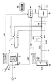
- FIG. 1 is an overall block diagram of a hybrid vehicle shown as an example of an electric vehicle according to Embodiment 1 of the present invention.
- the “hybrid vehicle” may be simply referred to as “vehicle”.
- hybrid vehicle 100 includes a power storage device 10, a system main relay 11, a converter 12, a main positive bus MPL, a main negative bus MNL, a smoothing capacitor C, a complementary capacitor.
- Machine 22 Hybrid vehicle 100 further includes inverters 30-1 and 30-2, motor generators 32-1 and 32-2, power split device 34, engine 36, and drive wheels 38.
- Hybrid vehicle 100 further includes voltage sensors 14, 18, 20, current sensor 16, and MG-ECU (Electronic Control Unit) 40. Further, the hybrid vehicle 100 is inserted into a charger 42, a charging ECU 46, power cables 50 and 43, a relay 51-1, and a connector 44 (for example, a house outlet) connected to an external power source 48. And a plug 45.
- the plug 45 has terminals 45A and 45B whose surfaces are exposed.
- Hybrid vehicle 100 further includes a power cable 53, a relay 51-2, and an inlet 54 for connecting to a connector 56 of charging cable 55.
- the charging cable 55 includes a plug 57 for connecting to a connector 59 (for example, an outlet of a house) connected to an external power source 58 and a CCID (Charging Circuit Interrupt Device) 60.
- a connector 59 for example, an outlet of a house
- CCID Charging Circuit Interrupt Device
- the power storage device 10 is a rechargeable DC power source, and includes, for example, a secondary battery such as nickel metal hydride or lithium ion, a large capacity capacitor, and the like. Power storage device 10 is connected to converter 12 via system main relay 11. System main relay 11 is provided between power storage device 10 and converter 12.
- Converter 12 is connected to main positive bus MPL and main negative bus MNL. Converter 12 performs voltage conversion between power storage device 10 and main positive bus MPL and main negative bus MNL based on signal PWC1 from MG-ECU 40.
- Auxiliary machine 22 is connected to positive line PL1 and negative line NL1 disposed between system main relay 11 and converter 12.
- Smoothing capacitor C is connected between main positive bus MPL and main negative bus MNL, and reduces power fluctuation components contained in main positive bus MPL and main negative bus MNL.
- Inverters 30-1 and 30-2 are connected in parallel to main positive bus MPL and main negative bus MNL.
- Inverter 30-1 drives motor generator 32-1 based on signal PWI1 from MG-ECU 40.
- Inverter 30-2 drives motor generator 32-2 based on signal PWI2 from MG-ECU 40.
- Motor generators 32-1 and 32-2 are AC rotating electric machines, for example, permanent magnet type synchronous motors having a rotor in which permanent magnets are embedded. Motor generators 32-1 and 32-2 are connected to power split device 34.
- Power split device 34 includes a planetary gear including a sun gear, a pinion gear, a carrier, and a ring gear.
- the pinion gear engages with the sun gear and the ring gear.
- the carrier supports the pinion gear so as to be capable of rotating, and is connected to the crankshaft of the engine 36.
- the sun gear is coupled to the rotation shaft of motor generator 32-1.
- the ring gear is connected to the rotation shaft of motor generator 32-2 and drive wheel 38.
- the motor generator 32-1 generates power using the power of the engine 36 divided by the power split device 34. For example, when the SOC of power storage device 10 decreases, engine 36 is started and power is generated by motor generator 32-1, and the generated power is supplied to the power storage device.
- motor generator 32-2 generates driving force using at least one of the electric power supplied from power storage device 10 and the electric power generated by motor generator 32-1.
- the driving force of the motor generator 32-2 is transmitted to the driving wheels 38.
- the motor generator 32-2 operates as a generator.
- motor generator 32-2 operates as a regenerative brake that converts and recovers the kinetic energy of the vehicle into electric power.
- MG-ECU 40 generates a signal PWC1 for driving converter 12 and outputs the generated signal PWC1 to converter 12.
- MG-ECU 40 generates signals PWI1 and PWI2 for driving motor generators 32-1 and 32-2, and outputs the generated signals PWI1 and PWI2 to inverters 30-1 and 30-2, respectively. .
- Charger 42 has an input end connected to power cable 50, and an output end connected to positive line PL1 and negative line NL1 disposed between system main relay 11 and converter 12.
- the charger 42 receives power supplied from a power source outside the vehicle (hereinafter also referred to as “external power source”).
- the charger 42 receives a control signal CHPW from the charging ECU 46.
- the charger 42 outputs a voltage suitable for charging the power storage device 10.
- charger 42 converts AC power from an external power source into DC power, and controls the voltage of the DC power to a voltage suitable for charging power storage device 10.
- the charger 42 converts the power supplied from the external power supply 48 to the plug 45 and It is received via cables 43 and 50.
- the plug 45 in this case is a power interface for receiving power from the external power supply 48.
- the inlet 54 of the hybrid vehicle 100 is connected to the connector 56 of the charging cable 55, the plug 57 of the charging cable 55 is connected to the connector 59 of the external power supply 58, and the relay 51-2 is closed.
- the charger 42 receives power supplied from the external power source 58 via the charging cable 55, the inlet 54, and the power cables 43 and 50.
- the inlet 54 is a power interface for receiving power from the external power supply 48.
- Voltage sensor 14 detects voltage VB1 of power storage device 10 and outputs the detected value to charging ECU 46.
- Current sensor 16 detects current IB ⁇ b> 1 that is input to and output from power storage device 10, and outputs the detected value to charging ECU 46.
- the voltage sensor 18 detects the voltage VL1 between the positive line PL1 and the negative line NL1, and outputs the detected value to the charging ECU 46.
- Voltage sensor 20 detects voltage VHM between main positive bus MPL and main negative bus MNL, and outputs the detected value to charging ECU 46.
- the charging ECU 46 sets the target value of the charging power (kW / h) of the power storage device 10 when the power storage device 10 is charged by the external power source 48 connected to the plug 45 or when the power storage device 10 is charged using the charging cable 55. PR is received from a vehicle ECU (not shown).
- the power cables 43 and 53 are provided in parallel to the input end of the charger 42.
- the charging ECU 46 turns on the relay 51-1 and turns off the relay 51-2.
- relay 51-1 is turned on, the end of power cable 43 is electrically connected to the input end of charger 42 via power cable 50.
- relay 51-2 is turned off, the end of power cable 53 is not connected to power cable 50, so the connection between the end of power cable 53 and the input end of charger 42 is interrupted. Thereby, the charger 42 receives the power supplied from the external power supply 48 via the plug 45 and the power cables 43 and 50.
- the charging ECU 46 turns off the relay 51-1.
- the relay 51-2 is turned on. Since relay 51-1 is turned off, the end of power cable 43 is not connected to power cable 50, so the connection between the end of power cable 43 and the input end of charger 42 is interrupted.
- the end of power cable 53 is electrically connected to the input end of charger 42 via power cable 50. Thereby, the charger 42 receives the electric power supplied from the external power supply 58 through the charging cable 55, the inlet 54, and the power cables 43 and 50.
- hybrid vehicle 100 according to Embodiment 1 includes a plurality of charging means (power cable 43 and inlet 54) for charging the power storage device. Since the user can use two charging methods, the optimal charging method can be selected according to the environment around the vehicle. For example, when the charging cable 55 is not mounted on the vehicle, the power storage device can be charged by removing the power cable 43 from the vehicle. Thereby, a user's convenience can be improved.
- FIG. 2 is a view for explaining the arrangement of the power cable 43 and the inlet 54 shown in FIG. 1 in the electric vehicle.
- FIG. 3 is a block diagram for illustrating a configuration related to charging of the power storage device in the first embodiment.
- a storage portion 71 for storing the power cable 43 is provided inside the vehicle.
- a cord reel 72 for winding the power cable 43 is provided inside the storage portion 71.
- an outlet 73 for the user to take out the power cable 43 stored in the storage unit 71 is formed on the surface of the vehicle body.
- a lid 74-1 that can be opened and closed is attached to the outlet 73 (housing 71).
- a lock device 77 for fixing the lid 74-1 in the closed state is installed in the storage portion 71. The lock device 77 locks the lid 74-1 in the closed state or releases the lock by the signal LCK1 from the charging ECU 46.
- the vehicle is provided with a storage portion 75 for storing the inlet 54.
- the storage portion 75 is formed with an opening for connecting the inlet 54 to the charging cable 55.
- an openable / closable lid 74-2 is attached to the opening (housing portion 75). By opening the lid 74-2, the inlet 54 is exposed to the outside of the vehicle.
- a lock device 78 for fixing the lid 74-2 in the closed state is installed in the storage unit 75. The lock device 78 locks the lid 74-2 in the closed state or releases the lock according to the signal LCK2 from the charging ECU 46.
- the connection detection signal CON is transmitted from the inlet 54 to the charging ECU in response to the connector being connected to the inlet 54.
- the vehicle is provided with a lid detection device 84 for detecting the open state and the closed state of the lid 74-1 and a lid detection device 85 for detecting the open state and the closed state of the lid 74-2.
- the lid detection device 84 transmits a signal LID1 indicating the open state or the closed state of the lid 74-1 to the charging ECU 46.
- the lid detection device 85 transmits a signal LID2 indicating the open state or the closed state of the lid 74-2 to the charging ECU 46.
- Relay 51-1 is turned on and off in response to signal SE1 from charging ECU 46.
- Relay 51-2 is turned on and off in response to signal SE2 from charging ECU 46.
- the vehicle further includes a display device 88.
- the display device 88 displays predetermined information in accordance with a control signal from the charging ECU 46.
- the display device 88 has a function of displaying information that can be recognized by the user, such as a liquid crystal display or a display lamp.
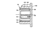
- FIG. 4 is a front view showing details of the inlet 54 to which the charging connector 56 shown in FIG. 1 is connected.
- FIG. 5 is a cross-sectional view of the inlet 54 taken along the line VV in FIG.
- the inlet 54 includes a main body 160 and connection terminals 166, 167, 168, 169, 170 as connection parts.
- the main body 160 is attached to the body of the vehicle 100 in the storage 75 shown in FIG.
- the main body 160 has a terminal protection part 161, an outer peripheral part 162, and a locking claw receiving part 165 as its constituent parts, and is formed by resin molding so that these parts are integrated.
- a fitting portion 173 is formed by the connection terminals 166, 167, 168, 169, 170, the terminal protection portion 161, and the outer peripheral portion 162.
- the terminal protection unit 161 is provided so as to surround each of the connection terminals 166 to 170.
- the terminal protection part 161 extends in a column shape along the extending direction of the connection terminals 166 to 170.
- the outer peripheral part 162 is provided on the outer periphery of the terminal protection part 161.
- a gap 164 extending in an annular shape is formed between the terminal protection part 161 and the outer peripheral part 162.
- the locking claw receiving portion 165 is provided at a position vertically above the terminal protection portion 161.
- the locking claw receiving portion 165 has a shape capable of locking the locking claw provided in the charging connector 56 shown in FIG.
- the main body 160 is attached so that the connection terminals 166 to 170 extend toward the side of the vehicle, which is the worker's standing position during charging.
- the main body portion 160 is further provided with a lid portion 171.
- the lid portion 171 is provided in the storage portion 75 shown in FIG. 2, and is provided further inside the lid 74-2 in FIG.
- the lid portion 171 is provided on the front surface of the terminal protection portion 161 and the outer peripheral portion 162 facing the connection terminals 166 to 170 so as to be opened and closed.
- An inner side surface 172 of the lid portion 171 contacts the terminal protection portion 161 and prevents intrusion of rainwater or the like into the terminal portion.
- a guide groove 158 is formed in the inlet 54.
- the guide groove 158 matches the function of guiding the charging connector 56 of the charging cable 55 toward a predetermined connection position in the inlet 54 with the positions of the connection terminals 166 to 170 and the connection terminals on the charge connector 56 side.
- the guide groove 158 is formed in the main body 160.
- the guide groove 158 is recessed from the inner peripheral surface of the outer peripheral portion 162 and extends in a direction parallel to the extending direction of the connection terminals 166 to 170.
- the guide groove 158 extends linearly at a position adjacent to the connection terminals 166 to 170.
- the guide groove 158 is formed at a position that is vertically lower than the terminal protection part 161.
- connection terminals 166 to 170 are configured to include two power cable terminals through which a current for charging flows, one ground terminal, and two signal line terminals.
- the connection terminals 166 to 170 are arranged at intervals with respect to the central axis of the terminal protection part 161 extending in a columnar shape in the circumferential direction around the axis.
- the terminals of the connection terminals 166 to 170 are arranged in a columnar space surrounded by the terminal protection part 161.
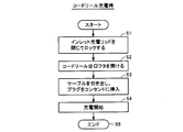
- FIG. 6 is a flowchart showing an operation procedure when charging using the cord reel.
- step S1 when charging using the cord reel 72, first, in step S1, the lid 74-2 on the inlet 54 side is closed to lock the lid 74-2.
- the lid 74-2 is locked by the locking device 78, and a signal LID2 indicating that the lid 74-2 is in the closed state is transmitted to the charging ECU 46 by the lid detecting device 85.
- step S2 an operation of opening the lid 74-1 on the cord reel 72 side is performed.
- a command to open the lid 74-1 is input to the charging ECU 46 by a switch operation or the like from the driver (operator)
- the charging ECU 46 transmits a signal LCK1 to the lock device 77 to release the lock.
- step S3 the driver (operator) pulls the cable 43 from the cord reel 72 and inserts the plug 45 into the outlet (wall outlet).
- step S4 charging is started, and the process ends in step S5.
- FIG. 7 is a flowchart for explaining an operation procedure when performing inlet charging.
- step S11 when charging is performed using the inlet 54, first, in step S11, the lid 74-1 on the cord reel 72 side is closed. Locked. Further, the lid detecting device 84 detects that the lid 74-1 is in the closed state, and a signal LID1 is transmitted to the charging ECU 46.
- step S13 a command to open the lid 74-2 on the inlet 54 side is input to the charging ECU 46 in accordance with an instruction from the driver (operator).
- the charging ECU 46 transmits a signal LCK2 to the lock device 78 to release the lock of the lid 74-2.
- the connector 56 of the charging cable 55 shown in FIG. 1 is inserted into the inlet 54 from the opening of the lid 74-2 opened in step S14.
- step S15 charging is started.
- step S16 the charging start procedure ends.
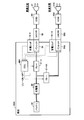
- FIG. 8 is a schematic diagram of the charging path of the vehicle 100. The problem in the case of having such two charging paths will be described using this schematic diagram.
- the power line is branched from the charger 42 to the inlet 54 side and the cord reel 72 side.
- Relays 51-1 and 51-2 are installed on these branch paths, respectively.
- the charging ECU 46 controls the relay 51-2 to conduct and charge through the charging path on the inlet 54 side.
- the charging ECU 46 controls the relay 51-1 to conduct and charge through the charging path on the cord reel 72 side.
- the charging ECU 46 conducts the relay that has been established earlier.
- a lock mechanism is provided on the charging lid 74-2 of the inlet 54 and the lid 74-1 of the cord reel outlet. Also, lid opening / closing information is sent to the charging ECU 46 by the lid detecting devices 84 and 85 shown in FIG.
- connection terminals 166 to 170 are provided with the terminal protection portion 161 around the structure, so that the peripheral objects are unlikely to come into contact with the terminals from the outside. .
- the inlet 54 is fixed to the vehicle.
- the plug 45 since the plug 45 is inserted into a household outlet (wall outlet), it can be moved freely to some extent, and the terminal is exposed. When a voltage is applied to these terminals from the vehicle side, there is a risk that a short circuit or a leakage current may occur due to contact with surrounding objects or the ground. For example, such a concern arises when welding occurs in the relays 51-1 and 51-2 when a voltage is applied from the outside via the connector 56 from the inlet side.
- FIG. 9 is a diagram for explaining permission / prohibition of charging at the time of relay welding.
- “conditional permission” indicates that charging on the path on the cord reel 72 side is permitted only when it is confirmed that the charging lid 74-2 is closed and locked.
- a plurality of charging paths of two or more systems are provided in the vehicle.
- the charging ECU 46 welds two or more of the plurality of relays respectively provided in the plurality of charging paths. If detected, charging of the power storage device 10 from the outside of the vehicle is prohibited. Then, charging from the selected charging path is permitted when the charging lid is closed and locked for a charging path other than the charging path selected for charging and where the relay is welded.
- the charging ECU 46 may display a charging path that does not permit charging on a display screen or the like to notify the user.
- FIG. 10 is a flowchart for explaining the charge permission judgment at the time of relay welding.
- determination of welding of relays 51-1 and 51-2 is performed at the end of the previous charging. Whether or not the relays 51-1 and 51-2 are welded is determined by whether or not the detection voltage of the voltage sensor provided at the inlet of the charger 42 drops when any of the relays 51-1 and 51-2 is turned off. Based on. The determination result is held in a memory inside the charging ECU 46.
- step S31 when the process is started, it is determined in step S31 whether or not the cord reel relay (relay 51-1) is welded. This welding determination is performed by reading out the result of the welding determination at the end of the previous charging.
- step S31 If it is determined in step S31 that the relay 51-1 is not welded, the process proceeds to step S32.
- step S32 it is determined whether or not the inlet relay (relay 51-2) is welded. If it is determined in step S32 that the relay 51-2 is not welded, in step S33, charging is possible through the charging path on the inlet 54 side, and charging is also performed on the charging path on the cord reel 72 side. Is determined to be possible, and the process proceeds to step S42.
- step S34 it is determined whether or not the lid 74-2 on the inlet 54 side is locked. If the lid detection device 85 detects that the lid 74-2 is open and it is determined that the lid 74-2 is not locked, the process proceeds to step S35. In step S35, charging on the inlet 54 side is possible, but it is determined that the charging path on the cord reel 72 side cannot be charged, and the process proceeds to step S42.
- step S34 when it is determined in step S34 that the lid 74-2 on the inlet 54 side is locked, that is, it is confirmed that the lid 74-2 is closed in the lid detection device 85, and the lid device 78 is confirmed by the lock device 78 from the charging ECU 46. If the lock is performed so that 74-2 is not opened, the process proceeds to step S36. In step S36, it is determined that charging is possible through the charging path on the inlet 54 side and charging is also possible via the charging path on the cord reel 72 side.
- step S31 If it is determined in step S31 that the relay 51-1 on the cord reel 72 side is welded, the process proceeds to step S37.
- step S37 it is determined whether or not the relay 51-2 on the inlet 54 side is welded. This determination is also made by reading the result of the welding check at the end of the previous charging.
- step S37 If it is determined in step S37 that the relay 51-2 on the inlet 54 side is not welded, the process proceeds to step S38.
- step S38 charging is impossible on the charging path on the inlet 54 side, but it is determined that charging is possible on the charging path on the cord reel 72 side, and the process proceeds to step S42.
- step S39 it is determined whether or not the lid 74-2 on the inlet 54 side is locked. That is, when the lid detecting device 85 detects that the lid 74-2 is open, it is determined that the lid 74-2 is not locked. On the other hand, when the lid 74-2 is in the closed state in the lid detection device 85 and the charging ECU 46 is locked using the lock device 78 so that the lid 74-2 is not opened, the lid 74-2 is Judged to be locked.
- step S39 If it is determined in step S39 that the lid 74-2 is not locked, the process proceeds to step S40.
- step S40 it is determined that charging cannot be performed on the charging path on the inlet 54 side, and charging is also impossible on the charging path on the cord reel 72 side, and the process proceeds to step S42.
- step S39 if it is determined in step S39 that the lid 74-2 on the inlet 54 side is locked, the process proceeds to step S41.
- step S41 it is determined that charging is not possible on the charging path on the inlet 54 side, but charging is possible on the charging path on the cord reel 72 side. Then, the process proceeds to step S42, and the determination as to whether or not charging is possible ends.
- the charging ECU 46 controls the locking devices 77 and 78, the relays 51-1 and 51-2, and the charger 42 based on the determination of whether or not charging is possible, which is determined in the flowchart described with reference to FIG.
- both of the relays 51-1 and 51-2 become conductive. It becomes a state and concerns such as short circuit and short circuit occur.
- both relays are welded, charging is prohibited.
- one of the lids is locked in a closed state and the connector portion is structured not to cause a short circuit or leakage, charging on the other side, that is, the cord reel side is permitted.
- FIG. 11 is a diagram schematically showing a charging path of a vehicle 100A according to a modification.
- a vehicle 100A shown in FIG. 11 includes a relay 51-1A, an inlet 54A, and a charging lid 741A in place of the relay 51-1, the cord reel 72 and the lid 74-1, and the plug 45 in FIG.
- a connector 56A is connected to the inlet 54A.
- the connector 56A is provided at the end of a charging cable for quick charging, and this cable is provided with a CCID 60A in the middle and a plug 57A at the other end.
- FIG. 12 is a diagram for explaining determination of permission / prohibition of charging in the modification of FIG.
- the conditional permission indicates that charging is permitted when it can be confirmed that the other charging lid is closed and locked.
- both the charging path on the normal charging side and the charging path on the quick charging side are permitted.
- condition permission in the case where “conditional permission” is displayed in FIG. 12, it may be prohibited, but charging may be permitted when it is confirmed that the other charging lid is closed and locked. In this way, charging can be performed as much as possible even during relay welding, which is advantageous when the vehicle is moved to a repair shop.
Landscapes
- Engineering & Computer Science (AREA)
- Power Engineering (AREA)
- Transportation (AREA)
- Mechanical Engineering (AREA)
- Life Sciences & Earth Sciences (AREA)
- Sustainable Development (AREA)
- Sustainable Energy (AREA)
- Electric Propulsion And Braking For Vehicles (AREA)
- Charge And Discharge Circuits For Batteries Or The Like (AREA)
Abstract
Description
この発明は他の局面では、上記いずれかの車両の電源システムを備えた車両である。
図1は、この発明の実施の形態1による電動車両の一例として示されるハイブリッド車両の全体ブロック図である。なお、以下では「ハイブリッド車両」を単に「車両」と呼ぶこともある。
図6は、コードリールを使用して充電する場合の操作手順を示したフローチャートである。
上記実施の形態1では、インレット54側の充電経路と、コードリール72側の充電経路の2系統の充電経路を有する場合の例を示した。他にも急速充電経路と普通充電経路のような2系統の充電経路が設けられる場合も考えられる。
図11に示す車両100Aは、図8におけるリレー51-1,コードリール72およびリッド74-1、プラグ45に代えてリレー51-1A,インレット54A,充電リッド741Aを含む。インレット54Aにはコネクタ56Aが接続される。コネクタ56Aは、急速充電用の充電ケーブルの端部に設けられており、このケーブルにはCCID60Aが中間に設けられプラグ57Aが他端に設けられている。
Claims (9)
- 蓄電装置(10)と、
前記蓄電装置に外部から電力を充電するための複数の充電経路(43,53)と、
前記複数の充電経路上にそれぞれ設けられ、電力の供給と遮断の切り替えを行なうための複数のリレー(51-1,51-2)と、
前記複数のリレーの溶着状態に基づいて前記複数の充電経路のうちいずれの充電経路から前記蓄電装置に対する充電を許可するかを選択する充電制御部(46)とを備える、車両の電源システム。 - 前記充電制御部は、前記複数の充電経路のうちの第1の充電経路に設けられたリレーの溶着を検出した場合には、前記複数の充電経路のうちの第1の充電経路以外の充電経路を用いた前記蓄電装置の充電を禁止する、請求の範囲第1項に記載の車両の電源システム。
- 前記充電制御部は、前記複数のリレーの2つ以上について溶着を検出した場合には、車両外部からの前記蓄電装置への充電を禁止する、請求の範囲第1項に記載の車両の電源システム。
- 前記複数の充電経路のいずれかを外部電源から遮断するための蓋(74-1,74-2)と、
前記蓋を遮断状態に固定するためのロック部(77,78)とをさらに備え、
前記充電制御部は、前記複数のリレーの溶着状態に加えて、前記蓋のロック状態にさらに基づいて、前記複数の充電経路のいずれの充電経路から前記蓄電装置に対する充電を許可するかを選択する、請求の範囲第1項に記載の車両の電源システム。 - 前記充電制御部は、前記蓋が外部電源から対応する充電経路を遮断する状態にロックされている場合には、他の充電経路からの充電を許可可能とする、請求の範囲第4項に記載の車両の電源システム。
- 前記複数の充電経路のうちの第1の充電経路は、充電インレット(54)による充電経路であり、
前記複数の充電経路のうちの第2の充電経路は、車両側に接続されたコードリール(72)および前記コードリールの先端に設けられた接続部(45)による充電経路である、請求の範囲第1項に記載の車両の電源システム。 - 前記複数の充電経路のうちの第1の充電経路は、急速充電を行なうための第1の外部電源が接続される充電経路(54A)であり、
前記複数の充電経路のうちの第2の充電経路は、前記急速充電よりも遅い速度で充電を行なうための第2の外部電源が接続される充電経路(54)である、請求の範囲第1項に記載の車両の電源システム。 - 前記充電制御部は、充電を許可しない充電経路をユーザに報知する、請求の範囲第1項に記載の車両の電源システム。
- 請求の範囲第1項~第8項のいずれか1項に記載の車両の電源システムを備えた車両。
Priority Applications (9)
| Application Number | Priority Date | Filing Date | Title |
|---|---|---|---|
| JP2012541693A JP5482908B2 (ja) | 2010-11-05 | 2010-11-05 | 車両の電源システムおよびそれを備える車両 |
| PCT/JP2010/069691 WO2012060009A1 (ja) | 2010-11-05 | 2010-11-05 | 車両の電源システムおよびそれを備える車両 |
| KR1020137002173A KR101440011B1 (ko) | 2010-11-05 | 2010-11-05 | 차량의 전원 시스템 및 그것을 구비하는 차량 |
| EP10859265.0A EP2637280B1 (en) | 2010-11-05 | 2010-11-05 | Power supply system for vehicle, and vehicle equipped with said power supply system |
| RU2013121550/07A RU2534017C1 (ru) | 2010-11-05 | 2010-11-05 | Система энергоснабжения для транспортного средства и транспортное средство, содержащее таковую |
| CN201080069966.0A CN103201927B (zh) | 2010-11-05 | 2010-11-05 | 车辆的电源系统及具备该电源系统的车辆 |
| BR112013011093A BR112013011093B1 (pt) | 2010-11-05 | 2010-11-05 | sistema de fornecimento de energia para veículo e veículo incluindo o mesmo |
| US13/699,694 US9393872B2 (en) | 2010-11-05 | 2010-11-05 | Power supply system for vehicle and vehicle including the same |
| ES10859265T ES2767082T3 (es) | 2010-11-05 | 2010-11-05 | Sistema de suministro de energía para vehículo, y vehículo equipado con dicho sistema de suministro de energía |
Applications Claiming Priority (1)
| Application Number | Priority Date | Filing Date | Title |
|---|---|---|---|
| PCT/JP2010/069691 WO2012060009A1 (ja) | 2010-11-05 | 2010-11-05 | 車両の電源システムおよびそれを備える車両 |
Publications (1)
| Publication Number | Publication Date |
|---|---|
| WO2012060009A1 true WO2012060009A1 (ja) | 2012-05-10 |
Family
ID=46024139
Family Applications (1)
| Application Number | Title | Priority Date | Filing Date |
|---|---|---|---|
| PCT/JP2010/069691 WO2012060009A1 (ja) | 2010-11-05 | 2010-11-05 | 車両の電源システムおよびそれを備える車両 |
Country Status (9)
| Country | Link |
|---|---|
| US (1) | US9393872B2 (ja) |
| EP (1) | EP2637280B1 (ja) |
| JP (1) | JP5482908B2 (ja) |
| KR (1) | KR101440011B1 (ja) |
| CN (1) | CN103201927B (ja) |
| BR (1) | BR112013011093B1 (ja) |
| ES (1) | ES2767082T3 (ja) |
| RU (1) | RU2534017C1 (ja) |
| WO (1) | WO2012060009A1 (ja) |
Cited By (6)
| Publication number | Priority date | Publication date | Assignee | Title |
|---|---|---|---|---|
| JP2013005528A (ja) * | 2011-06-14 | 2013-01-07 | Toyota Motor Corp | 回路異常検出装置および方法 |
| JP2014087154A (ja) * | 2012-10-23 | 2014-05-12 | Toyota Motor Corp | 電力供給装置 |
| JP2014193042A (ja) * | 2013-03-27 | 2014-10-06 | Panasonic Corp | 車両用電力装置 |
| JP2018121399A (ja) * | 2017-01-23 | 2018-08-02 | 三菱電機株式会社 | 電池遮断回路 |
| JP6448825B1 (ja) * | 2018-01-11 | 2019-01-09 | 三菱電機株式会社 | 充電制御装置 |
| JP2019090210A (ja) * | 2017-11-14 | 2019-06-13 | トヨタ自動車株式会社 | 車両のロック装置 |
Families Citing this family (19)
| Publication number | Priority date | Publication date | Assignee | Title |
|---|---|---|---|---|
| US9033076B2 (en) * | 2011-05-12 | 2015-05-19 | Toyota Jidosha Kabushiki Kaisha | Vehicle |
| JP5477409B2 (ja) * | 2012-03-12 | 2014-04-23 | 株式会社デンソー | 電源システム |
| US9463701B2 (en) * | 2014-10-15 | 2016-10-11 | Ford Global Technologies, Llc | Electrified vehicle charger |
| US10377247B2 (en) * | 2015-07-27 | 2019-08-13 | Ford Global Technologies, Llc | High voltage battery contactor arrangement for DC fast charging |
| KR101673822B1 (ko) * | 2015-11-18 | 2016-11-07 | 현대자동차주식회사 | 친환경 차량의 릴레이 융착 검출 장치 및 그 방법 |
| CN105730242B (zh) * | 2016-01-28 | 2018-08-21 | 纽福克斯光电科技(上海)有限公司 | 一种基于辅助引擎的充电系统及方法 |
| JP6553556B2 (ja) * | 2016-08-08 | 2019-07-31 | トヨタ自動車株式会社 | 自動車 |
| JP6443425B2 (ja) * | 2016-10-18 | 2018-12-26 | トヨタ自動車株式会社 | 車両 |
| KR20180049391A (ko) * | 2016-11-01 | 2018-05-11 | 주식회사 비긴스 | 전기차, 및 전기차 충전 시스템 |
| KR20180058447A (ko) * | 2016-11-24 | 2018-06-01 | (주) 대경엔지니어링 | 전기차 차량탑재형 이동형 충전기 |
| DE102017208599B4 (de) * | 2017-05-22 | 2022-02-03 | Audi Ag | Kraftwagen mit einer Anschlusseinrichtung |
| JP6819515B2 (ja) * | 2017-08-29 | 2021-01-27 | トヨタ自動車株式会社 | 車両 |
| JP7159792B2 (ja) * | 2018-10-31 | 2022-10-25 | トヨタ自動車株式会社 | 電動車両 |
| JP7020375B2 (ja) * | 2018-11-07 | 2022-02-16 | トヨタ自動車株式会社 | 電動車両 |
| CN109823188A (zh) * | 2019-01-10 | 2019-05-31 | 乾碳国际公司 | 混动商用车再生制动和缓速系统 |
| JP7249164B2 (ja) * | 2019-02-05 | 2023-03-30 | 株式会社Subaru | 車両 |
| JP7430068B2 (ja) * | 2020-01-31 | 2024-02-09 | 株式会社小松製作所 | 作業車両用表示制御装置及び作業車両 |
| JP2022039337A (ja) * | 2020-08-28 | 2022-03-10 | トヨタ自動車株式会社 | 充電システム、車両、充電制御装置、及び充電方法 |
| JP2024048130A (ja) * | 2022-09-27 | 2024-04-08 | トヨタ自動車株式会社 | 車両 |
Citations (8)
| Publication number | Priority date | Publication date | Assignee | Title |
|---|---|---|---|---|
| JPH07274308A (ja) * | 1994-03-31 | 1995-10-20 | Nissan Motor Co Ltd | 電気自動車の充電制御装置 |
| WO1997010967A1 (fr) | 1995-09-18 | 1997-03-27 | Seiko Epson Corporation | Mecanisme de securite pour un vehicule electrique |
| JPH11299008A (ja) * | 1998-04-06 | 1999-10-29 | Harness Syst Tech Res Ltd | 電気自動車の充電装置 |
| JP2003244832A (ja) | 2002-02-15 | 2003-08-29 | Mitsubishi Motors Corp | 電気自動車 |
| JP2009077557A (ja) * | 2007-09-21 | 2009-04-09 | Fuji Heavy Ind Ltd | 電気自動車の充電装置 |
| JP2009136110A (ja) * | 2007-11-30 | 2009-06-18 | Toyota Motor Corp | 車両の充電制御装置 |
| JP2010183795A (ja) * | 2009-02-09 | 2010-08-19 | Mitsubishi Motors Corp | 電気自動車の充電リレー溶着判定装置 |
| JP2010187467A (ja) * | 2009-02-12 | 2010-08-26 | Omron Corp | 車両用バッテリ充電装置および給電口の制御方法 |
Family Cites Families (11)
| Publication number | Priority date | Publication date | Assignee | Title |
|---|---|---|---|---|
| US4313078A (en) * | 1979-12-05 | 1982-01-26 | Rca Corporation | Battery charging system |
| RU2013842C1 (ru) * | 1991-07-09 | 1994-05-30 | Николай Алексеевич Шумаков | Система для заряда аккумуляторной батареи |
| JP3069498B2 (ja) * | 1994-09-01 | 2000-07-24 | 富士通株式会社 | 充放電装置および電子機器 |
| JP3554057B2 (ja) * | 1995-02-06 | 2004-08-11 | 本田技研工業株式会社 | 電気自動車用蓄電池充電制御装置 |
| CN1217809C (zh) * | 2000-02-18 | 2005-09-07 | 三洋电机株式会社 | 电动车辆的继电器熔敷检测装置 |
| RU2234783C2 (ru) * | 2001-02-19 | 2004-08-20 | Шумаков Николай Алексеевич | Система заряда аккумуляторной батареи |
| RU45872U1 (ru) * | 2004-03-30 | 2005-05-27 | Общество С Ограниченной Ответственностью "Агроимпорт" | Система электрооборудования транспортного средства |
| JP4599260B2 (ja) * | 2004-09-28 | 2010-12-15 | プライムアースEvエナジー株式会社 | 電源制御装置、電源制御方法、プログラム及び記録媒体 |
| JP4367391B2 (ja) * | 2005-09-01 | 2009-11-18 | トヨタ自動車株式会社 | 充電制御装置および電動車両 |
| JP4810564B2 (ja) * | 2008-11-17 | 2011-11-09 | トヨタ自動車株式会社 | 電動車両用の充電ケーブルおよびその管理方法 |
| JP5412999B2 (ja) | 2009-07-02 | 2014-02-12 | トヨタ自動車株式会社 | 電動車両 |
-
2010
- 2010-11-05 RU RU2013121550/07A patent/RU2534017C1/ru active
- 2010-11-05 US US13/699,694 patent/US9393872B2/en active Active
- 2010-11-05 CN CN201080069966.0A patent/CN103201927B/zh active Active
- 2010-11-05 WO PCT/JP2010/069691 patent/WO2012060009A1/ja active Application Filing
- 2010-11-05 ES ES10859265T patent/ES2767082T3/es active Active
- 2010-11-05 JP JP2012541693A patent/JP5482908B2/ja active Active
- 2010-11-05 EP EP10859265.0A patent/EP2637280B1/en active Active
- 2010-11-05 KR KR1020137002173A patent/KR101440011B1/ko active IP Right Grant
- 2010-11-05 BR BR112013011093A patent/BR112013011093B1/pt active IP Right Grant
Patent Citations (8)
| Publication number | Priority date | Publication date | Assignee | Title |
|---|---|---|---|---|
| JPH07274308A (ja) * | 1994-03-31 | 1995-10-20 | Nissan Motor Co Ltd | 電気自動車の充電制御装置 |
| WO1997010967A1 (fr) | 1995-09-18 | 1997-03-27 | Seiko Epson Corporation | Mecanisme de securite pour un vehicule electrique |
| JPH11299008A (ja) * | 1998-04-06 | 1999-10-29 | Harness Syst Tech Res Ltd | 電気自動車の充電装置 |
| JP2003244832A (ja) | 2002-02-15 | 2003-08-29 | Mitsubishi Motors Corp | 電気自動車 |
| JP2009077557A (ja) * | 2007-09-21 | 2009-04-09 | Fuji Heavy Ind Ltd | 電気自動車の充電装置 |
| JP2009136110A (ja) * | 2007-11-30 | 2009-06-18 | Toyota Motor Corp | 車両の充電制御装置 |
| JP2010183795A (ja) * | 2009-02-09 | 2010-08-19 | Mitsubishi Motors Corp | 電気自動車の充電リレー溶着判定装置 |
| JP2010187467A (ja) * | 2009-02-12 | 2010-08-26 | Omron Corp | 車両用バッテリ充電装置および給電口の制御方法 |
Non-Patent Citations (1)
| Title |
|---|
| See also references of EP2637280A4 |
Cited By (7)
| Publication number | Priority date | Publication date | Assignee | Title |
|---|---|---|---|---|
| JP2013005528A (ja) * | 2011-06-14 | 2013-01-07 | Toyota Motor Corp | 回路異常検出装置および方法 |
| JP2014087154A (ja) * | 2012-10-23 | 2014-05-12 | Toyota Motor Corp | 電力供給装置 |
| JP2014193042A (ja) * | 2013-03-27 | 2014-10-06 | Panasonic Corp | 車両用電力装置 |
| JP2018121399A (ja) * | 2017-01-23 | 2018-08-02 | 三菱電機株式会社 | 電池遮断回路 |
| JP2019090210A (ja) * | 2017-11-14 | 2019-06-13 | トヨタ自動車株式会社 | 車両のロック装置 |
| JP6448825B1 (ja) * | 2018-01-11 | 2019-01-09 | 三菱電機株式会社 | 充電制御装置 |
| JP2019122207A (ja) * | 2018-01-11 | 2019-07-22 | 三菱電機株式会社 | 充電制御装置 |
Also Published As
| Publication number | Publication date |
|---|---|
| JP5482908B2 (ja) | 2014-05-07 |
| RU2534017C1 (ru) | 2014-11-27 |
| BR112013011093A2 (pt) | 2016-08-23 |
| JPWO2012060009A1 (ja) | 2014-05-12 |
| BR112013011093B1 (pt) | 2019-12-03 |
| EP2637280B1 (en) | 2019-12-25 |
| EP2637280A1 (en) | 2013-09-11 |
| KR101440011B1 (ko) | 2014-09-12 |
| KR20130036757A (ko) | 2013-04-12 |
| ES2767082T3 (es) | 2020-06-16 |
| CN103201927B (zh) | 2016-02-10 |
| EP2637280A4 (en) | 2017-12-20 |
| US9393872B2 (en) | 2016-07-19 |
| CN103201927A (zh) | 2013-07-10 |
| RU2013121550A (ru) | 2014-12-10 |
| US20130249282A1 (en) | 2013-09-26 |
Similar Documents
| Publication | Publication Date | Title |
|---|---|---|
| JP5482908B2 (ja) | 車両の電源システムおよびそれを備える車両 | |
| JP5077376B2 (ja) | 車両 | |
| JP4984010B2 (ja) | 車両の電源システムおよびそれを備える電動車両 | |
| EP3092149B1 (en) | Hybrid vehicle with means for disconnection of a depleted auxiliary battery in order to allow for more rapid main battery charging | |
| JP6521920B2 (ja) | 車両およびその制御方法 | |
| JP4375472B2 (ja) | 車両の充電制御装置 | |
| EP2211439B1 (en) | Charge system failure judging device and failure judging method | |
| JP5412999B2 (ja) | 電動車両 | |
| JP5348251B2 (ja) | 電線格納装置およびそれを搭載する車両、給電装置 | |
| JP5292186B2 (ja) | 電動車両の電源システム | |
| JP5359413B2 (ja) | 車両の充電システムおよび車両 | |
| WO2013042216A1 (ja) | 電動車両の充電システムおよび充電制御方法 | |
| KR20100039902A (ko) | 차량 | |
| JP2010098845A (ja) | 車両の充電制御装置および車両 | |
| JP2010148213A (ja) | 充電制御システム、制御装置、充電制御方法及び制御方法 | |
| JP5884700B2 (ja) | 車両の制御装置および車両 | |
| WO2012117550A1 (ja) | 車両のシフトロック装置 | |
| JP2013240191A (ja) | 車両および車両の制御方法 | |
| WO2012081120A1 (ja) | コード格納部を備えた車両およびその制御方法 | |
| JP2017103950A (ja) | 電源装置 | |
| JP5835180B2 (ja) | 車両 | |
| JP2009071898A (ja) | 蓄電機構の充電制御システムおよびその制御方法 | |
| JP5675541B2 (ja) | 車両 | |
| JP2009291037A (ja) | 電動車両および電動車両の異常検知方法 |
Legal Events
| Date | Code | Title | Description |
|---|---|---|---|
| 121 | Ep: the epo has been informed by wipo that ep was designated in this application |
Ref document number: 10859265 Country of ref document: EP Kind code of ref document: A1 |
|
| WWE | Wipo information: entry into national phase |
Ref document number: 13699694 Country of ref document: US |
|
| WWE | Wipo information: entry into national phase |
Ref document number: 2012541693 Country of ref document: JP Ref document number: 10549/DELNP/2012 Country of ref document: IN |
|
| ENP | Entry into the national phase |
Ref document number: 20137002173 Country of ref document: KR Kind code of ref document: A |
|
| WWE | Wipo information: entry into national phase |
Ref document number: 2010859265 Country of ref document: EP |
|
| NENP | Non-entry into the national phase |
Ref country code: DE |
|
| ENP | Entry into the national phase |
Ref document number: 2013121550 Country of ref document: RU Kind code of ref document: A |
|
| REG | Reference to national code |
Ref country code: BR Ref legal event code: B01A Ref document number: 112013011093 Country of ref document: BR |
|
| ENP | Entry into the national phase |
Ref document number: 112013011093 Country of ref document: BR Kind code of ref document: A2 Effective date: 20130503 |