WO2012020700A1 - 積層型固体電池 - Google Patents
積層型固体電池 Download PDFInfo
- Publication number
- WO2012020700A1 WO2012020700A1 PCT/JP2011/067926 JP2011067926W WO2012020700A1 WO 2012020700 A1 WO2012020700 A1 WO 2012020700A1 JP 2011067926 W JP2011067926 W JP 2011067926W WO 2012020700 A1 WO2012020700 A1 WO 2012020700A1
- Authority
- WO
- WIPO (PCT)
- Prior art keywords
- layer
- electrode layer
- stacked
- current collecting
- negative electrode
- Prior art date
- Legal status (The legal status is an assumption and is not a legal conclusion. Google has not performed a legal analysis and makes no representation as to the accuracy of the status listed.)
- Ceased
Links
Images




Classifications
-
- H—ELECTRICITY
- H01—ELECTRIC ELEMENTS
- H01M—PROCESSES OR MEANS, e.g. BATTERIES, FOR THE DIRECT CONVERSION OF CHEMICAL ENERGY INTO ELECTRICAL ENERGY
- H01M4/00—Electrodes
- H01M4/02—Electrodes composed of, or comprising, active material
- H01M4/64—Carriers or collectors
- H01M4/66—Selection of materials
-
- H—ELECTRICITY
- H01—ELECTRIC ELEMENTS
- H01M—PROCESSES OR MEANS, e.g. BATTERIES, FOR THE DIRECT CONVERSION OF CHEMICAL ENERGY INTO ELECTRICAL ENERGY
- H01M10/00—Secondary cells; Manufacture thereof
- H01M10/04—Construction or manufacture in general
- H01M10/0436—Small-sized flat cells or batteries for portable equipment
- H01M10/044—Small-sized flat cells or batteries for portable equipment with bipolar electrodes
-
- H—ELECTRICITY
- H01—ELECTRIC ELEMENTS
- H01M—PROCESSES OR MEANS, e.g. BATTERIES, FOR THE DIRECT CONVERSION OF CHEMICAL ENERGY INTO ELECTRICAL ENERGY
- H01M10/00—Secondary cells; Manufacture thereof
- H01M10/05—Accumulators with non-aqueous electrolyte
- H01M10/052—Li-accumulators
-
- H—ELECTRICITY
- H01—ELECTRIC ELEMENTS
- H01M—PROCESSES OR MEANS, e.g. BATTERIES, FOR THE DIRECT CONVERSION OF CHEMICAL ENERGY INTO ELECTRICAL ENERGY
- H01M10/00—Secondary cells; Manufacture thereof
- H01M10/05—Accumulators with non-aqueous electrolyte
- H01M10/058—Construction or manufacture
- H01M10/0585—Construction or manufacture of accumulators having only flat construction elements, i.e. flat positive electrodes, flat negative electrodes and flat separators
-
- H—ELECTRICITY
- H01—ELECTRIC ELEMENTS
- H01M—PROCESSES OR MEANS, e.g. BATTERIES, FOR THE DIRECT CONVERSION OF CHEMICAL ENERGY INTO ELECTRICAL ENERGY
- H01M50/00—Constructional details or processes of manufacture of the non-active parts of electrochemical cells other than fuel cells, e.g. hybrid cells
- H01M50/50—Current conducting connections for cells or batteries
- H01M50/502—Interconnectors for connecting terminals of adjacent batteries; Interconnectors for connecting cells outside a battery casing
- H01M50/503—Interconnectors for connecting terminals of adjacent batteries; Interconnectors for connecting cells outside a battery casing characterised by the shape of the interconnectors
-
- H—ELECTRICITY
- H01—ELECTRIC ELEMENTS
- H01M—PROCESSES OR MEANS, e.g. BATTERIES, FOR THE DIRECT CONVERSION OF CHEMICAL ENERGY INTO ELECTRICAL ENERGY
- H01M50/00—Constructional details or processes of manufacture of the non-active parts of electrochemical cells other than fuel cells, e.g. hybrid cells
- H01M50/50—Current conducting connections for cells or batteries
- H01M50/502—Interconnectors for connecting terminals of adjacent batteries; Interconnectors for connecting cells outside a battery casing
- H01M50/509—Interconnectors for connecting terminals of adjacent batteries; Interconnectors for connecting cells outside a battery casing characterised by the type of connection, e.g. mixed connections
- H01M50/512—Connection only in parallel
-
- Y—GENERAL TAGGING OF NEW TECHNOLOGICAL DEVELOPMENTS; GENERAL TAGGING OF CROSS-SECTIONAL TECHNOLOGIES SPANNING OVER SEVERAL SECTIONS OF THE IPC; TECHNICAL SUBJECTS COVERED BY FORMER USPC CROSS-REFERENCE ART COLLECTIONS [XRACs] AND DIGESTS
- Y02—TECHNOLOGIES OR APPLICATIONS FOR MITIGATION OR ADAPTATION AGAINST CLIMATE CHANGE
- Y02E—REDUCTION OF GREENHOUSE GAS [GHG] EMISSIONS, RELATED TO ENERGY GENERATION, TRANSMISSION OR DISTRIBUTION
- Y02E60/00—Enabling technologies; Technologies with a potential or indirect contribution to GHG emissions mitigation
- Y02E60/10—Energy storage using batteries
-
- Y—GENERAL TAGGING OF NEW TECHNOLOGICAL DEVELOPMENTS; GENERAL TAGGING OF CROSS-SECTIONAL TECHNOLOGIES SPANNING OVER SEVERAL SECTIONS OF THE IPC; TECHNICAL SUBJECTS COVERED BY FORMER USPC CROSS-REFERENCE ART COLLECTIONS [XRACs] AND DIGESTS
- Y02—TECHNOLOGIES OR APPLICATIONS FOR MITIGATION OR ADAPTATION AGAINST CLIMATE CHANGE
- Y02P—CLIMATE CHANGE MITIGATION TECHNOLOGIES IN THE PRODUCTION OR PROCESSING OF GOODS
- Y02P70/00—Climate change mitigation technologies in the production process for final industrial or consumer products
- Y02P70/50—Manufacturing or production processes characterised by the final manufactured product
Definitions
- the present invention generally relates to a stacked solid state battery, and more particularly to a stacked solid state battery configured to connect unit cells in series.
- batteries particularly secondary batteries
- a lithium ion secondary battery is known to have a relatively large energy density.
- a liquid electrolyte electrolytic solution
- organic solvent has been conventionally used as a medium for moving ions.
- electrolytic solution electrolytic solution
- secondary batteries using an electrolytic solution have problems such as leakage of the electrolytic solution. In view of this, development of a stacked solid battery in which all the constituent elements are made of solid using a solid electrolyte is underway.
- Patent Document 1 Japanese Patent Application Laid-Open No. 2004-158222 (hereinafter referred to as Patent Document 1), a thin film solid lithium ion secondary battery is used as one cell, and the battery cell is arranged in a plurality of stages.
- Patent Document 1 Japanese Patent Application Laid-Open No. 2004-158222
- a thin film solid lithium ion secondary battery is used as one cell, and the battery cell is arranged in a plurality of stages.
- the structure of a stacked multilayer battery is disclosed.
- a current collecting layer (metal film) is formed in a stacked solid battery in which a plurality of power generating elements in which a positive electrode layer, a solid electrolyte layer, a negative electrode layer, and a current collecting layer are laminated.
- a current collecting layer metal film
- a plurality of power generation elements each including a positive electrode layer, a solid electrolyte layer, a negative electrode layer, and a current collecting layer are stacked via an insulating layer electrically and ionically conductive.
- the extraction tabs provided on the outer peripheral edge of the current collecting layer are arranged in a direction perpendicular to the stack direction and pulled out to the outside of the stack, and the pull-out tabs are insulated.
- a connection via hole penetrating the layer is provided, and the via hole can be embedded with a metal electrode, and a series type, a parallel type, or a series-parallel type connection can be selected by a combination of these connections.
- a single battery is electrically connected via a current collecting layer by arranging a positive electrode layer on one side of the current collecting layer and a negative electrode layer on the opposite side. Connected in series.
- the positive electrode layer and the negative electrode layer are ion-conductive through the current collecting layer, only the positively conductive positive electrode layer and the negative electrode layer are discharged, so that the battery characteristics of the stacked solid battery are remarkably improved. Will be reduced.
- it is necessary to devise measures such as making the current collecting layer a continuous film without pores or ensuring a sufficient thickness of the current collecting layer. .
- each unit cell is electrically and ionically insulated by an insulating layer, and each unit cell is separated by a pull-out tab arranged outside the unit cell. Electrically connected in series and / or in parallel. Since an insulating layer is used to insulate each unit cell electronically and ionically, even if the current collecting layer is substantially ion conductive, the positive electrode is interposed through the current collecting layer. The layer and the negative electrode layer are not electrically conductive. Thereby, it becomes possible to prevent the battery characteristics of the stacked solid battery from deteriorating.
- the cells are electrically connected to the outside of the unit cell by using the extraction tab arranged for each unit cell, approximately the same number of extraction tabs as the unit cell are required.
- an object of the present invention is to have a simple configuration and to connect a plurality of unit cells constituting a stacked solid battery in series, and to ion-conduct the positive electrode layer and the negative electrode layer in two adjacent unit cells. It is another object of the present invention to provide a stacked solid state battery that can be insulated.
- the stacked solid battery according to the present invention includes first and second unit cells, and an internal current collecting layer disposed so as to be interposed between the first and second unit cells.
- the first second unit cell includes a positive electrode layer, a solid electrolyte layer, and a negative electrode layer, which are sequentially stacked.
- the internal current collecting layer has one side surface that contacts the positive electrode layer of the first unit cell and the other side surface that contacts the negative electrode layer of the second unit cell.
- the internal current collecting layer includes a specific conductive material that is insulative in terms of ion conduction.
- the internal current collecting layer interposed between the first and second unit cells includes a specific conductive material that is ionically insulating, so that two adjacent unit cells are In addition to being able to be electrically connected in series, the positive electrode layer and the negative electrode layer can be efficiently insulated in an ion conductive manner in two adjacent unit cells. Thereby, high characteristics can be obtained.
- the external current collecting member such as a drawer tab is eliminated, the cells constituting the stacked solid battery are electrically connected in series, and the positive electrode layer and the negative electrode layer are efficiently insulated in an ion conductive manner. Can do. Thereby, it is possible to obtain a stacked solid battery excellent in space utilization and cost.
- the internal current collecting layer further includes an electron conductive material.
- the electron conductive material includes at least one selected from conductive oxides, metals, and carbon materials.
- the specific conductive material preferably has a structure similar to that of the solid electrolyte material contained in at least one layer selected from the positive electrode layer and the negative electrode layer.
- the shrinkage rate of the positive electrode layer or the negative electrode layer, the solid electrolyte layer, and the internal current collecting layer can be approximated. Thereby, generation
- the solid electrolyte material and the specific conductive material include a compound containing lithium.
- the solid electrolyte material and the specific conductive material include a lithium-containing phosphate compound.
- a stacked solid state battery can be fabricated by dense integrated sintering.
- the solid electrolyte material and the specific conductive material include a lithium-containing phosphate compound having a NASICON structure.
- a specific conductive material that is insulatively conductive is produced by reducing the molar ratio of lithium. can do.
- the lithium-containing phosphate compound having a NASICON structure contained in the specific conductive material has a chemical formula Li 1 + x M x M ′ 2 ⁇ x (PO 4 ) 3 (where x is 0 ⁇ x ⁇ 1, M Is preferably Al or Ga, and M ′ is one or more elements selected from the group consisting of Ti, Ge and Zr).
- x is 0 ⁇ x ⁇ 1
- M Is preferably Al or Ga
- M ′ is one or more elements selected from the group consisting of Ti, Ge and Zr.
- part of P in the above chemical formula may be substituted with B, Si, or the like.
- an active material contained in at least one layer selected from the positive electrode layer and the negative electrode layer and a solid electrolyte material contained in at least one layer selected from the positive electrode layer and the negative electrode layer
- the solid electrolyte material contained in the solid electrolyte layer and the specific conductive material contained in the internal current collecting layer preferably contain a lithium-containing phosphate compound.
- the positive electrode layer or the negative electrode layer, the solid electrolyte layer, and the internal current collecting layer share a phosphoric acid skeleton, so that a low-resistance multilayer solid battery is more densely and integrally sintered. Can be produced.
- n-1 internal current collecting layers are arranged between n unit cells each composed of a positive electrode layer, a solid electrolyte layer, and a negative electrode layer, which are sequentially stacked.
- a stacked solid state battery formed by stacking n unit cells, and has electronic conductivity on a surface not adjacent to the internal current collecting layer of the unit cells located in the first and nth stages. It is preferable to arrange an external electrode.
- the electrical resistance of the stacked solid state battery can be reduced by arranging the external electrode having electronic conductivity as described above.
- n ⁇ 1 internal current collecting layers are arranged between n unit cells each composed of a positive electrode layer, a solid electrolyte layer, and a negative electrode layer, which are sequentially stacked.
- m power generation elements are formed by stacking n unit cells, and m-1 external electrodes are arranged between the m power generation elements and stacked to form a stacked solid state battery.
- Two power generation elements adjacent to one external electrode are stacked and electrically connected so that the positive electrode side or the negative electrode layer side of the unit cell is adjacent to both surfaces of the external electrode.
- External electrodes are also arranged on the surfaces not adjacent to the external electrodes of the power generation elements located at the first and m-th stages. Further, the external electrodes having the same pole are electrically connected by an external current collecting member.
- the stacked solid state battery of the present invention includes a structure in which at least two power generation elements are electrically connected in parallel.
- each power generation element configured by connecting n cells in series is stacked via an external electrode between m power generation elements, and an external current collector is connected between the external electrodes that have the same pole.
- the conductive material forming the external electrode preferably contains at least one selected from conductive oxides and metals.
- a bipolar stacked solid battery in which a plurality of single cells are connected in series via the internal current collecting layer is provided. Obtainable.
- a plurality of unit cells constituting a stacked solid battery can be connected in series, and the positive electrode layer and the negative electrode layer can be ionically insulated in two adjacent unit cells. Therefore, a stacked solid battery having high characteristics can be obtained.
- a laminated body serving as a basic structure of a laminated solid battery will be described as a first embodiment of the present invention.
- the planar shape of the laminate is not limited, but will be described as being generally rectangular, for example.
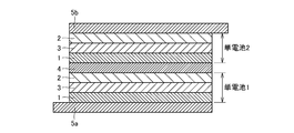
- each of (unit cell 1) and (unit cell 2) is composed of a positive electrode layer 1, a solid electrolyte layer 3, and a negative electrode layer 2 that are stacked in order.
- the positive electrode layer 1 of (single cell 2) is adjacent to one side surface (upper surface in FIG. 1) of the internal current collecting layer 4, and the negative electrode of (single cell 1) is disposed on the other side surface (lower surface in FIG. 1) of the internal current collecting layer 4.
- the (unit cell 1), the (unit cell 2), and the internal current collection layer 4 are laminated so that the layer 2 is adjacent.
- the inner current collecting layer 4 includes at least a specific conductive material that is ionically insulating.
- the bipolar stacked solid battery 10 can be obtained. Thereby, the high output type stacked solid battery 10 can be obtained.
- the internal current collecting layer 4 interposed between the (unit cell 1) and the (unit cell 2) includes a specific conductive material that is ionically insulating, so that they are adjacent to each other. Two unit cells can be electrically connected in series, and the positive electrode layer 1 and the negative electrode layer 2 can be efficiently ionically insulated in two adjacent unit cells. Thereby, high characteristics can be obtained.
- the external current collecting member such as a drawer tab is eliminated, the cells constituting the stacked solid battery 10 are electrically connected in series, and the positive electrode layer 1 and the negative electrode layer 2 are efficiently ionically conductive. Can be insulated. Thereby, the laminated solid battery 10 excellent in space utilization and cost can be obtained.
- the internal current collecting layer 4 further includes an electron conductive material.
- the internal current collecting layer 4 includes at least one type of electron conductive material selected from the group consisting of conductive oxides, metals, and carbon materials, and a specific conductive material that is ionically conductive and insulating. Is preferred.
- the metal used as the electron conductive material is particularly preferably nickel, copper, silver or the like having a low electric resistance.
- the electron conductivity of the internal current collecting layer 4 can be increased.
- the positive electrode layer 1 and the negative electrode layer 2 stacked via the internal current collecting layer 4 are ionized.
- the positive electrode layer 1 and the negative electrode layer 2 stacked via the internal current collecting layer 4 can be brought into electrical contact. it can.
- the stacked solids electrically connected in series without causing deterioration of the battery characteristics due to the discharge of the positively conductive positive electrode layer 1 and negative electrode layer 2.
- the battery 10 can be obtained.
- the specific conductive material preferably has a structure similar to that of the solid electrolyte material contained in at least one of the positive electrode layer 1 and the negative electrode layer 2.
- the shrinkage rate of the positive electrode layer 1 or the negative electrode layer 2, the solid electrolyte layer 3, and the internal current collecting layer 4 can be approximated. Thereby, generation
- the solid electrolyte material and the specific conductive material include a compound containing lithium. Furthermore, it is preferable that the solid electrolyte material and the specific conductive material include a lithium-containing phosphate compound.
- the stacked solid battery 10 can be fabricated by dense and integral sintering.
- a dense laminate having improved adhesion between the positive electrode layer 1, the negative electrode layer 2, the solid electrolyte layer 3, and the internal current collecting layer 4 can be obtained without peeling or cracking.
- the solid electrolyte material and the specific conductive material include a lithium-containing phosphate compound having a NASICON structure.
- a specific conductive material that is insulatively conductive is produced by reducing the molar ratio of lithium. can do.
- Lithium-containing phosphoric acid compound having a NASICON-type structure contained in the specific conductive material has the formula Li x M y (PO 4) 3 ( in the chemical formula, x is 1 ⁇ x ⁇ 2, y is 1 ⁇ y ⁇ 2, M is preferably represented by one or more elements selected from the group consisting of Ti, Ge, Al, Ga and Zr). In this case, part of P in the above chemical formula may be substituted with B, Si, or the like.
- lithium-containing phosphate compound having a NASICON type structure used for the solid electrolyte material and the specific conductive material
- the lithium-containing phosphate compound having a NASICON structure used for the solid electrolyte material and the specific conductive material may be a compound containing a crystal phase of a lithium-containing phosphate compound having a NASICON structure, or NASICON by heat treatment. You may use the glass which precipitates the crystal phase of the lithium containing phosphate compound which has a type
- the material used for the solid electrolyte material may be a material that has ionic conductivity and is so small that electron conductivity is negligible.
- examples of such a material include lithium halide, lithium nitride, lithium oxyacid salt, and derivatives thereof.
- Li-PO system compounds such as lithium phosphate (Li 3 PO 4 ), LIPON (LiPO 4 ⁇ x N x ) in which nitrogen is mixed with lithium phosphate, and Li—Si—O such as Li 4 SiO 4
- Li—Si—O such as Li 4 SiO 4
- the material used for the above-mentioned ion conductive insulating specific conductive material can be ionized by reducing the molar ratio of lithium based on the composition of the lithium-containing phosphate compound.
- a compound having a perovskite structure having a stoichiometric composition such as (La 1/2 Li 1/2 ) TiO 3 can be used.
- the active material contained in at least one of the positive electrode layer 1 and the negative electrode layer 2 and the solid contained in at least one of the positive electrode layer 1 and the negative electrode layer 2 include a lithium-containing phosphate compound.
- the positive electrode layer 1 or the negative electrode layer 2, the solid electrolyte layer 3, and the internal current collecting layer 4 share the phosphoric acid skeleton, so that the low-resistance stacked solid battery 10 is more It can be produced by dense integral sintering.
- the type of the above-mentioned active material is not limited, as the positive electrode active material, Li 3 V 2 (PO 4 ) 3, LiFePO 4, lithium-containing phosphate compound having a NASICON-type structure of LiMnPO 4 or the like, or A lithium-containing phosphate compound having an olivine type structure can be used. Further, a layered compound such as LiCoO 2 , LiCo 1/3 Ni 1/3 Mn 1/3 O 2 , lithium having a spinel structure such as LiMn 2 O 4 , LiNi 0.5 Mn 1.5 O 4 , Li 4 Ti 5 O 12 A containing compound, a phosphoric acid compound such as LiFePO 4 or LiMnPO 4 can be used as the positive electrode active material.
- Examples of the negative electrode active material include graphite-lithium compounds, lithium alloys such as Li-Al, oxides such as Li 3 V 2 (PO 4 ) 3 , Li 3 Fe 2 (PO 4 ) 3 , and Li 4 Ti 5 O 12 . Etc. can be used.
- the method for forming the internal current collecting layer 4 is not particularly limited.
- the material is prepared in a slurry form and laminated with green sheets, or the material is prepared in a paste form and screen-printed. May be.
- the method for forming the green sheet is not particularly limited, but may be performed using a die coater, a comma coater, a screen printing method, or the like.
- the method for laminating the green sheets is not particularly limited, but may be performed using a hot isostatic press (HIP), a cold isostatic press (CIP), a hydrostatic press (WIP), or the like.
- HIP hot isostatic press
- CIP cold isostatic press
- WIP hydrostatic press
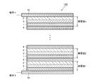
- n (cells 1 to n) are stacked via the internal current collecting layer 4 in the same manner as in FIG. N (cells 1 to n) are collected as n-1 internal current collectors so that the positive electrode layer 1 (negative electrode layer 2) of each (cells 1 to n) is arranged on the same side in the stacking direction.
- External electrodes 5a and 5b are arranged on the outer surface of the laminate formed by stacking n unit cells. Specifically, in the lowermost stage (unit cell 1) which is one end portion of the laminate, an external electrode 5a having electron conductivity is provided on the surface of the positive electrode layer 1 that is not adjacent to the solid electrolyte layer 3. Has been placed.
- an external electrode 5b having electron conductivity is disposed on the surface of the negative electrode layer 2 that is not adjacent to the solid electrolyte layer 3 in the uppermost stage (unit cell n) that is the other end of the laminate. Charging and discharging are performed by connecting the external electrode 5a to the positive terminal and connecting the external electrode 5b to the negative terminal.
- an insulating material that is ionically conductive is used as the specific conductive material included in the internal current collecting layer 4, thereby being stacked via the internal current collecting layer 4.
- the positive electrode layer 1 and the negative electrode layer 2 are laminated via the internal current collecting layer 4 by insulating the positive electrode layer 1 and the negative electrode layer 2 in an ion conductive manner and including an electron conductive material in the internal current collecting layer 4. 2 can be brought into electrical contact. Accordingly, the n unit cells constituting the stacked solid battery 100 are electrically connected in series without using an external current collecting member such as a drawer tab, and the positive electrode layer 1 and the negative electrode layer 2 are efficiently connected. Can be ionically insulated. Thereby, the stacked solid battery 100 excellent in space utilization and cost can be obtained.
- the method of configuring the stacked solid battery 100 of the present embodiment is not particularly limited.
- the (unit cells 1 to n) and the internal current collecting layer 4 are configured, and these are configured as a set of external electrodes
- a method in which the stacked solid battery 100 is sequentially stacked so as to be sandwiched between 5a and 5b, or the positive electrode layer 1, the solid electrolyte layer 3, the negative electrode layer 2, and the internal current collecting layer 4 are sequentially stacked on the external electrode 5a.
- a method of stacking the external electrode 5b to form the stacked solid battery 100 may be used.
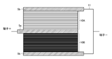
- FIG. 3 two power generating elements 10A and 10B configured by connecting n unit cells in series are stacked via an external electrode 5a and electrically connected in parallel to form a stacked type.
- a solid battery is constructed.
- each of the two power generating elements 10A and 10B is configured by stacking n (cells 1 to n) via n-1 internal current collecting layers 4.
- n unit cells are electrically connected in series in the same manner as the stacked solid battery 100 shown in FIG.
- the power generation element 10A is formed as a first stack by stacking n unit cells, and power generation is performed as a second stack by stacking n unit cells.
- Element 10B is formed.
- An external electrode 5a is disposed as a first external electrode between the positive electrode layer 1 positioned on one side surface of the power generation element 10A and the positive electrode layer 1 positioned on one side surface of the power generation element 10B. That is, the positive electrode layer 1 is adjacent to both surfaces of the external electrode 5a interposed between the two power generation elements 10A and 10B.
- an external electrode 5b is disposed as a second external electrode.
- an external electrode 5b is disposed as a third external electrode.
- the external electrodes 5b are also arranged on the uppermost and lowermost surfaces that are the end portions of the multilayer body shown in FIG.
- the two external electrodes 5 b and 5 b are electrically connected through the external current collecting member 11. Accordingly, the two power generation elements 10A and 10B are electrically connected in parallel via the external electrodes 5a and 5b. Charging and discharging are performed by connecting the external electrode 5a to the positive terminal and connecting the external electrode 5b to the negative terminal.
- the power generation elements 10A and 10B in which n pieces of (cells 1 to n) are electrically connected in series are electrically connected in parallel to each other. It becomes possible to express twice the capacity at the same voltage as the stacked solid battery 100 shown in FIG.
- the stacked solid battery is described in which the positive electrode layer 1 is adjacent to both surfaces of the external electrode 5a interposed between the two power generation elements 10A and 10B.
- Two power generation elements 10A and 10B may be arranged so that 2 are adjacent to each other.
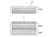
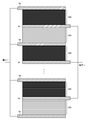
- FIGS. 6 to 7 a plurality of power generation elements 10A and 10B configured by connecting n single cells in series are connected between two adjacent power generation elements 10A and 10B.
- a stacked solid state battery is configured by stacking via 5b and electrically connecting in parallel.
- FIG. 6 shows a cross-sectional structure of the stacked solid state battery when the number of power generation elements is an even number.
- FIG. 7 shows a cross-sectional structure of the stacked solid state battery when the number of power generation elements is an odd number.
- Each of the two power generating elements 10A and 10B is configured by stacking n pieces (unit cells 1 to n) via n-1 internal current collecting layers 4. That is, in each of the power generation elements 10A and 10B, n unit cells are electrically connected in series in the same manner as the stacked solid battery 100 shown in FIG.
- External electrode 5a is arranged as a first external electrode between positive electrode layer 1 positioned on one side surface of power generation element 10A and positive electrode layer 1 positioned on one side surface of power generation element 10B.
- an external electrode 5b is arranged as a first external electrode between the negative electrode layer 2 positioned on one side surface of the power generation element 10A and the negative electrode layer 2 positioned on one side surface of the power generation element 10B. That is, the positive electrode layer 1 is adjacent to both surfaces of the external electrode 5a interposed between the two power generation elements 10A and 10B.
- the negative electrode layer 1 is adjacent to both surfaces of the external electrode 5b interposed between the two power generation elements 10A and 10B.
- the external electrode 5a or the external electrode 5b is also arranged on the uppermost and lowermost surfaces which are the end portions of the laminated body shown in FIGS.
- the plurality of external electrodes 5a and 5a and the plurality of external electrodes 5b and 5b are electrically connected. Therefore, the plurality of power generation elements 10A and 10B are electrically connected in parallel via the external electrodes 5a and 5b. Charging and discharging are performed by connecting the external electrode 5a to the positive terminal and connecting the external electrode 5b to the negative terminal.
- the number of power generating elements 10A and 10B in which n (cells 1 to n) are electrically connected in series is electrically m, that is, an even number, or By connecting in an odd number in parallel, it becomes possible to develop a capacity of m times, that is, an even number or an odd number, with the same voltage as the stacked solid battery 100 shown in FIG.
- each component can be realized using the materials shown below.
- the solid electrolyte layer 3 contains the above-described solid electrolyte material as a main material.
- the positive electrode layer 1 includes the above-described mixture of the positive electrode active material and the solid electrolyte material as a main material. Moreover, the positive electrode layer 1 may contain a small amount of carbon or the like as a conductive agent.
- the negative electrode layer 2 contains the above-mentioned mixture of the negative electrode active material and the solid electrolyte material as a main material. Moreover, the negative electrode layer 2 may contain a small amount of carbon or the like as a conductive agent.
- LVP lithium-containing vanadium phosphate compound
- Carbon powder as a conductive material was added to the obtained fired powder and mixed in a mortar.
- LAGP Nasicon type aluminum-substituted lithium lithium germanium phosphate (Li 1.5 Al 0.5 Ge 1.5 (PO 4 ) 3 )
- LAGP Nasicon type aluminum-substituted lithium lithium germanium phosphate
- polyvinyl alcohol as a binder in toluene.
- the obtained binder solution was mixed to obtain a solid electrolyte layer slurry.
- the main material and a binder solution obtained by dissolving polyvinyl alcohol as a binder in toluene were mixed to prepare a positive electrode layer slurry and a negative electrode layer slurry made of the same material.
- the positive electrode layer slurry, the negative electrode layer slurry, the solid electrolyte layer slurry, and the internal current collecting layer slurry prepared as described above are formed into a thickness of 50 ⁇ m using a doctor blade, thereby forming a positive electrode layer slurry.
- a sheet, a sheet for negative electrode layer, a sheet for solid electrolyte layer, and a sheet for internal current collecting layer were prepared.
- a sheet for a positive electrode layer 1, a sheet for a negative electrode layer 2, a sheet for a solid electrolyte layer 3, and a sheet for an internal current collecting layer 4 punched into a disk shape having a diameter of 12 mm are laminated in the configuration of a laminate as shown in FIG. Then, thermocompression bonding was performed at a temperature of 60 ° C. and a pressure of 1 ton to obtain a laminate for the stacked solid battery 10.
- the positive electrode layer 1 was composed of one positive electrode layer sheet
- the negative electrode layer 2 was composed of two negative electrode layer sheets.
- the same sheet as the sheet for the internal current collecting layer 4 is used, and the surfaces of the (unit cell 1) and (unit cell 2) that are not adjacent to the internal current collecting layer 4
- the sheets for external electrodes 5a and 5b were laminated.
- the laminate for a solid battery obtained as described above was sandwiched between two alumina ceramic plates and baked at a temperature of 500 ° C. for 2 hours in an oxygen gas atmosphere to remove polyvinyl alcohol. Thereafter, firing was performed at 700 ° C. for 2 hours in a nitrogen gas atmosphere, and the positive electrode layer 1, the negative electrode layer 2, the solid electrolyte layer 3, the internal current collecting layer 4, and the external electrodes 5a and 5b were sintered and joined.
- a platinum layer was formed by sputtering on the outside of the external electrodes 5a and 5b of the stacked solid battery shown in FIG.
- the stacked solid battery was dried at a temperature of 100 ° C. and then sealed with a 2032 type coin cell.
- the LAGP crystal powder is used as the solid electrolyte material, but the same effect can be obtained by using the LAGP amorphous powder.
- the negative electrode active material using LVP has been described.
- the negative electrode active material graphite-lithium compounds, lithium alloys such as Li-Al, Li 3 V 2 (PO 4 ) 3, Li 3 Fe 2 (PO 4) 3, Li 4 Ti 5 similar effect by using the oxide of O 12, etc. is obtained.
- a bipolar stacked solid battery in which a plurality of single cells are connected in series with an internal current collecting layer interposed therebetween can be obtained.
- a stacked solid state battery can be obtained.
Landscapes
- Chemical & Material Sciences (AREA)
- Chemical Kinetics & Catalysis (AREA)
- Electrochemistry (AREA)
- General Chemical & Material Sciences (AREA)
- Engineering & Computer Science (AREA)
- Manufacturing & Machinery (AREA)
- Materials Engineering (AREA)
- Secondary Cells (AREA)
Abstract
Description
Claims (11)
- 各々が順に積み重ねられた正極層、固体電解質層および負極層から構成される少なくとも第1と第2の単電池と、
前記第1の単電池の正極層に接触する一方側面と、前記第2の単電池の負極層に接触する他方側面とを有し、前記第1と第2の単電池の間に介在するように配置された内部集電層と、を備え、
前記内部集電層は、電子伝導材料を含み、さらに、イオン伝導的に絶縁性の特定伝導材料を含む、積層型固体電池。 - 前記電子伝導材料は、導電性酸化物、金属および炭素材料からなる群より選ばれた少なくとも一種を含む、請求項1に記載の積層型固体電池。
- 前記特定伝導材料は、前記正極層および前記負極層より選ばれた少なくとも一つの層に含まれる固体電解質材料と類似の構造を有する、請求項1または請求項2に記載の積層型固体電池。
- 前記固体電解質材料と前記特定伝導材料とが、リチウムを含む化合物を含む、請求項3に記載の積層型固体電池。
- 前記固体電解質材料と前記特定伝導材料とが、リチウム含有リン酸化合物を含む、請求項3に記載の積層型固体電池。
- 前記固体電解質材料と前記特定伝導材料とが、ナシコン型構造を有するリチウム含有リン酸化合物を含む、請求項3に記載の積層型固体電池。
- 前記特定伝導材料に含まれるナシコン型構造を有するリチウム含有リン酸化合物が、化学式Li1+xMxM'2-x(PO4)3(化学式中、xは0≦x≦1、MはAlまたはGa、M'はTi、GeおよびZrからなる群より選ばれた1種以上の元素である)で表わされる、請求項6に記載の積層型固体電池。
- 前記正極層および前記負極層より選ばれた少なくとも一つの層に含まれる活物質材料と、前記正極層および前記負極層より選ばれた少なくとも一つの層に含まれる固体電解質材料と、前記固体電解質層に含まれる固体電解質材料と、前記内部集電層に含まれる前記特定伝導材料とが、リチウム含有リン酸化合物を含む、請求項1に記載の積層型固体電池。
- 各々が順に積み重ねられた正極層、固体電解質層および負極層から構成されるn個の単電池の間に前記内部集電層をn-1個配置して、前記n個の前記単電池を積み重ねることにより形成された積層型固体電池であって、
1段目およびn段目に位置する前記単電池の前記内部集電層に隣接しない面に電子伝導性を有する外部電極を配置する、請求項1から請求項8までのいずれか1項に記載の積層型固体電池。 - 各々が順に積み重ねられた正極層、固体電解質層および負極層から構成されるn個の単電池の間に前記内部集電層をn-1個配置して、前記n個の前記単電池を積み重ねることにより発電要素をm個形成し、該m個の発電要素の間にm-1個の外部電極を配置して積み重ねることにより形成された積層型固体二次電池であって、
1つの前記外部電極に隣接する2つの前記発電要素を、前記外部電極の両面に前記単電池の前記正極層側または前記負極層側が隣接するように積み重ねるとともに電気的に接続し、
1段目およびm段目に位置する前記発電要素の前記外部電極に隣接しない面にも外部電極を配置し、
さらに同じ極となる前記外部電極間を外部集電部材で電気的に接続することにより、少なくとも2つの前記発電要素を電気的に並列に接続した構造を含む、請求項1から請求項8までのいずれか1項に記載の積層型固体電池。 - 前記外部電極を形成する導電材料は、導電性酸化物および金属より選ばれた少なくとも一種を含む、請求項9または請求項10に記載の積層型固体電池。
Priority Applications (3)
| Application Number | Priority Date | Filing Date | Title |
|---|---|---|---|
| CN201180038834.6A CN103053061B (zh) | 2010-08-09 | 2011-08-05 | 层叠型固体电池 |
| JP2012528658A JP5644858B2 (ja) | 2010-08-09 | 2011-08-05 | 積層型固体電池 |
| US13/762,439 US9118068B2 (en) | 2010-08-09 | 2013-02-08 | Layered solid-state battery |
Applications Claiming Priority (2)
| Application Number | Priority Date | Filing Date | Title |
|---|---|---|---|
| JP2010-178501 | 2010-08-09 | ||
| JP2010178501 | 2010-08-09 |
Related Child Applications (1)
| Application Number | Title | Priority Date | Filing Date |
|---|---|---|---|
| US13/762,439 Continuation US9118068B2 (en) | 2010-08-09 | 2013-02-08 | Layered solid-state battery |
Publications (1)
| Publication Number | Publication Date |
|---|---|
| WO2012020700A1 true WO2012020700A1 (ja) | 2012-02-16 |
Family
ID=45567668
Family Applications (1)
| Application Number | Title | Priority Date | Filing Date |
|---|---|---|---|
| PCT/JP2011/067926 Ceased WO2012020700A1 (ja) | 2010-08-09 | 2011-08-05 | 積層型固体電池 |
Country Status (4)
| Country | Link |
|---|---|
| US (1) | US9118068B2 (ja) |
| JP (1) | JP5644858B2 (ja) |
| CN (1) | CN103053061B (ja) |
| WO (1) | WO2012020700A1 (ja) |
Cited By (13)
| Publication number | Priority date | Publication date | Assignee | Title |
|---|---|---|---|---|
| WO2013153603A1 (ja) * | 2012-04-09 | 2013-10-17 | 株式会社日本マイクロニクス | 二次電池 |
| JP2014093189A (ja) * | 2012-11-02 | 2014-05-19 | Kyocera Corp | 二次電池およびその使用方法、ならびに蓄電装置 |
| JP2015053158A (ja) * | 2013-09-06 | 2015-03-19 | 株式会社村田製作所 | 積層型固体電池 |
| JP2016001527A (ja) * | 2014-06-11 | 2016-01-07 | Fdk株式会社 | 全固体電池の製造方法、及び全固体電池 |
| JP2017157271A (ja) * | 2016-02-29 | 2017-09-07 | 日立造船株式会社 | 全固体二次電池およびその製造方法 |
| WO2017150354A1 (ja) * | 2016-02-29 | 2017-09-08 | 日立造船株式会社 | 全固体二次電池およびその製造方法 |
| JP2017183121A (ja) * | 2016-03-31 | 2017-10-05 | 日立造船株式会社 | 全固体二次電池の製造方法 |
| WO2018087970A1 (ja) * | 2016-11-08 | 2018-05-17 | 株式会社村田製作所 | 固体電池、固体電池の製造方法、電池パック、車両、蓄電システム、電動工具及び電子機器 |
| JP2019087534A (ja) * | 2017-11-03 | 2019-06-06 | アドバンスト バッテリー コンセプツ エルエルシー | バイポーラバッテリ組立体 |
| US10707523B2 (en) | 2016-09-20 | 2020-07-07 | Kabushiki Kaisha Toshiba | Solid electrolyte, lithium battery, battery pack, and vehicle |
| JP2021034158A (ja) * | 2019-08-20 | 2021-03-01 | 本田技研工業株式会社 | リチウムイオン二次電池用電極、およびリチウムイオン二次電池 |
| JP2021150191A (ja) * | 2020-03-19 | 2021-09-27 | 本田技研工業株式会社 | バイポーラ電極を用いた二次電池 |
| WO2021256519A1 (ja) * | 2020-06-17 | 2021-12-23 | 株式会社村田製作所 | 固体電池 |
Families Citing this family (31)
| Publication number | Priority date | Publication date | Assignee | Title |
|---|---|---|---|---|
| JP6048396B2 (ja) * | 2013-12-26 | 2016-12-21 | トヨタ自動車株式会社 | 全固体電池の製造方法 |
| EP3451435A4 (en) * | 2016-04-26 | 2019-11-20 | Hitachi Zosen Corporation | ACCUMULATOR FULLY SOLID |
| JP6685951B2 (ja) * | 2017-02-21 | 2020-04-22 | 株式会社東芝 | 二次電池、複合電解質、電池パック及び車両 |
| TWI676315B (zh) * | 2017-10-20 | 2019-11-01 | 輝能科技股份有限公司 | 複合式電池芯 |
| US11056716B2 (en) | 2017-11-02 | 2021-07-06 | Taiyo Yuden Co., Ltd. | All solid battery |
| US11264641B2 (en) | 2018-01-10 | 2022-03-01 | Samsung Electronics Co., Ltd. | All-solid secondary battery, multilayered all-solid secondary battery, and method of manufacturing all-solid secondary battery |
| US11056722B2 (en) | 2018-02-08 | 2021-07-06 | International Business Machines Corporation | Tool and method of fabricating a self-aligned solid state thin film battery |
| US10720670B2 (en) * | 2018-02-08 | 2020-07-21 | International Business Machines Corporation | Self-aligned 3D solid state thin film battery |
| US10679853B2 (en) | 2018-02-08 | 2020-06-09 | International Business Machines Corporation | Self-aligned, over etched hard mask fabrication method and structure |
| JPWO2019220981A1 (ja) * | 2018-05-15 | 2021-02-12 | 株式会社村田製作所 | 固体電池、電池モジュールおよび固体電池の充電方法 |
| US12136704B2 (en) * | 2018-05-30 | 2024-11-05 | Robert Bosch Gmbh | Battery including bipolar cells that have an edge insulating device |
| JP2020024921A (ja) * | 2018-08-08 | 2020-02-13 | 輝能科技股▲分▼有限公司Prologium Technology Co., Ltd. | 水平複合給電エレメント群 |
| CN113169373B (zh) * | 2018-12-06 | 2024-04-19 | 株式会社村田制作所 | 固体电池 |
| CN111799426A (zh) * | 2019-04-08 | 2020-10-20 | 青岛九环新越新能源科技股份有限公司 | 储能设备用双极导电薄膜 |
| JP7431540B2 (ja) * | 2019-09-12 | 2024-02-15 | 太陽誘電株式会社 | 全固体電池および電池モジュール |
| CN110556568A (zh) * | 2019-09-27 | 2019-12-10 | 安徽坤宇塑金新能源技术有限公司 | 高电压单体固态锂离子电池及其制备方法 |
| WO2021070927A1 (ja) * | 2019-10-11 | 2021-04-15 | 株式会社村田製作所 | 固体電池 |
| CN110635107A (zh) * | 2019-10-24 | 2019-12-31 | 邦泰宏图(深圳)科技有限责任公司 | 无基材的双极固态锂离子电池及其制作方法 |
| CN112786969B (zh) * | 2019-11-08 | 2023-08-29 | 辉能科技股份有限公司 | 锂电池结构及其极层结构 |
| CN114747063A (zh) * | 2019-12-04 | 2022-07-12 | 株式会社村田制作所 | 固体电池 |
| WO2021124809A1 (ja) * | 2019-12-19 | 2021-06-24 | 株式会社村田製作所 | 固体電池 |
| US11677098B2 (en) * | 2019-12-27 | 2023-06-13 | Taiyo Yuden Co., Ltd. | All solid battery and manufacturing method of the same |
| WO2021149382A1 (ja) * | 2020-01-24 | 2021-07-29 | パナソニックIpマネジメント株式会社 | 電池 |
| JP7461705B2 (ja) * | 2020-03-18 | 2024-04-04 | 本田技研工業株式会社 | バイポーラ電極を用いた二次電池 |
| CN115461909B (zh) * | 2020-06-30 | 2026-04-21 | 宁德新能源科技有限公司 | 一种电化学装置及包含该电化学装置的电子装置 |
| JP7701167B2 (ja) * | 2021-03-11 | 2025-07-01 | 本田技研工業株式会社 | 固体電池 |
| CN113206289A (zh) * | 2021-04-19 | 2021-08-03 | 湖北工业大学 | 一种无界面抗粉化的全玻璃固态钠离子电池及制备方法 |
| JP7528873B2 (ja) * | 2021-06-18 | 2024-08-06 | トヨタ自動車株式会社 | 電池 |
| CN114024037A (zh) * | 2021-10-28 | 2022-02-08 | 中国第一汽车股份有限公司 | 一种固态电芯及其制备方法和储能装置 |
| KR20240040879A (ko) * | 2022-09-22 | 2024-03-29 | 주식회사 엘지에너지솔루션 | 전극 조립체 및 이의 제조방법 |
| WO2024077584A1 (zh) * | 2022-10-14 | 2024-04-18 | 宁德时代新能源科技股份有限公司 | 电池模块及其制备方法、电池包和用电装置 |
Citations (4)
| Publication number | Priority date | Publication date | Assignee | Title |
|---|---|---|---|---|
| JP2001015152A (ja) * | 1999-06-29 | 2001-01-19 | Kyocera Corp | 全固体積層電池 |
| JP2004158343A (ja) * | 2002-11-07 | 2004-06-03 | Nissan Motor Co Ltd | バイポーラ電池 |
| JP2008027659A (ja) * | 2006-07-19 | 2008-02-07 | Toyota Motor Corp | 組電池 |
| JP2008251219A (ja) * | 2007-03-29 | 2008-10-16 | Tdk Corp | 全固体リチウムイオン二次電池及びその製造方法 |
Family Cites Families (6)
| Publication number | Priority date | Publication date | Assignee | Title |
|---|---|---|---|---|
| WO1999067836A1 (fr) * | 1998-06-25 | 1999-12-29 | Mitsubishi Denki Kabushiki Kaisha | Cellule et procede de production |
| JP2004158222A (ja) * | 2002-11-01 | 2004-06-03 | Mamoru Baba | 多層積層電池 |
| US7914932B2 (en) * | 2006-02-24 | 2011-03-29 | Ngk Insulators, Ltd. | All-solid-state battery |
| US8338038B2 (en) * | 2008-09-12 | 2012-12-25 | Ceramatec, Inc | Electrochemical cell comprising ionically conductive membrane and porous multiphase electrode |
| JP5488590B2 (ja) * | 2009-04-09 | 2014-05-14 | 日産自動車株式会社 | 二次電池用集電体及びこれを用いた二次電池 |
| WO2011033702A1 (ja) * | 2009-09-17 | 2011-03-24 | 株式会社村田製作所 | 電池間分離構造体とそれを備えた積層型固体二次電池 |
-
2011
- 2011-08-05 JP JP2012528658A patent/JP5644858B2/ja active Active
- 2011-08-05 CN CN201180038834.6A patent/CN103053061B/zh active Active
- 2011-08-05 WO PCT/JP2011/067926 patent/WO2012020700A1/ja not_active Ceased
-
2013
- 2013-02-08 US US13/762,439 patent/US9118068B2/en active Active
Patent Citations (4)
| Publication number | Priority date | Publication date | Assignee | Title |
|---|---|---|---|---|
| JP2001015152A (ja) * | 1999-06-29 | 2001-01-19 | Kyocera Corp | 全固体積層電池 |
| JP2004158343A (ja) * | 2002-11-07 | 2004-06-03 | Nissan Motor Co Ltd | バイポーラ電池 |
| JP2008027659A (ja) * | 2006-07-19 | 2008-02-07 | Toyota Motor Corp | 組電池 |
| JP2008251219A (ja) * | 2007-03-29 | 2008-10-16 | Tdk Corp | 全固体リチウムイオン二次電池及びその製造方法 |
Cited By (27)
| Publication number | Priority date | Publication date | Assignee | Title |
|---|---|---|---|---|
| EP2838148A4 (en) * | 2012-04-09 | 2015-07-29 | Nihon Micronics Kk | SECONDARY BATTERY |
| WO2013154046A1 (ja) * | 2012-04-09 | 2013-10-17 | 株式会社日本マイクロニクス | 二次電池 |
| KR20140108593A (ko) * | 2012-04-09 | 2014-09-11 | 가부시키가이샤 니혼 마이크로닉스 | 이차전지 |
| CN104221200A (zh) * | 2012-04-09 | 2014-12-17 | 日本麦可罗尼克斯股份有限公司 | 二次电池 |
| CN104221200B (zh) * | 2012-04-09 | 2018-11-02 | 日本麦可罗尼克斯股份有限公司 | 二次电池 |
| TWI504038B (zh) * | 2012-04-09 | 2015-10-11 | Nihon Micronics Kk | Secondary battery |
| JPWO2013154046A1 (ja) * | 2012-04-09 | 2015-12-17 | 株式会社日本マイクロニクス | 二次電池 |
| KR101616883B1 (ko) * | 2012-04-09 | 2016-04-29 | 가부시키가이샤 니혼 마이크로닉스 | 이차전지 |
| US10347893B2 (en) | 2012-04-09 | 2019-07-09 | Kabushiki Kaisha Nihon Micronics | Secondary battery |
| WO2013153603A1 (ja) * | 2012-04-09 | 2013-10-17 | 株式会社日本マイクロニクス | 二次電池 |
| JP2014093189A (ja) * | 2012-11-02 | 2014-05-19 | Kyocera Corp | 二次電池およびその使用方法、ならびに蓄電装置 |
| JP2015053158A (ja) * | 2013-09-06 | 2015-03-19 | 株式会社村田製作所 | 積層型固体電池 |
| JP2016001527A (ja) * | 2014-06-11 | 2016-01-07 | Fdk株式会社 | 全固体電池の製造方法、及び全固体電池 |
| WO2017150354A1 (ja) * | 2016-02-29 | 2017-09-08 | 日立造船株式会社 | 全固体二次電池およびその製造方法 |
| US11101497B2 (en) | 2016-02-29 | 2021-08-24 | Hitachi Zosen Corporation | All-solid state secondary battery and method for manufacturing same |
| JP2017157271A (ja) * | 2016-02-29 | 2017-09-07 | 日立造船株式会社 | 全固体二次電池およびその製造方法 |
| JP2017183121A (ja) * | 2016-03-31 | 2017-10-05 | 日立造船株式会社 | 全固体二次電池の製造方法 |
| US10707523B2 (en) | 2016-09-20 | 2020-07-07 | Kabushiki Kaisha Toshiba | Solid electrolyte, lithium battery, battery pack, and vehicle |
| JPWO2018087970A1 (ja) * | 2016-11-08 | 2019-09-26 | 株式会社村田製作所 | 固体電池、固体電池の製造方法、電池パック、車両、蓄電システム、電動工具及び電子機器 |
| WO2018087970A1 (ja) * | 2016-11-08 | 2018-05-17 | 株式会社村田製作所 | 固体電池、固体電池の製造方法、電池パック、車両、蓄電システム、電動工具及び電子機器 |
| US11050091B2 (en) | 2016-11-08 | 2021-06-29 | Murata Manufacturing Co., Ltd. | Solid battery, manufacturing method of solid battery, battery pack, vehicle, power storage system, power tool, and electronic equipment |
| JP2019087534A (ja) * | 2017-11-03 | 2019-06-06 | アドバンスト バッテリー コンセプツ エルエルシー | バイポーラバッテリ組立体 |
| JP2021034158A (ja) * | 2019-08-20 | 2021-03-01 | 本田技研工業株式会社 | リチウムイオン二次電池用電極、およびリチウムイオン二次電池 |
| JP7082096B2 (ja) | 2019-08-20 | 2022-06-07 | 本田技研工業株式会社 | リチウムイオン二次電池用電極、およびリチウムイオン二次電池 |
| JP2021150191A (ja) * | 2020-03-19 | 2021-09-27 | 本田技研工業株式会社 | バイポーラ電極を用いた二次電池 |
| JP7461765B2 (ja) | 2020-03-19 | 2024-04-04 | 本田技研工業株式会社 | バイポーラ電極を用いた二次電池 |
| WO2021256519A1 (ja) * | 2020-06-17 | 2021-12-23 | 株式会社村田製作所 | 固体電池 |
Also Published As
| Publication number | Publication date |
|---|---|
| JP5644858B2 (ja) | 2014-12-24 |
| US9118068B2 (en) | 2015-08-25 |
| CN103053061A (zh) | 2013-04-17 |
| US20130149592A1 (en) | 2013-06-13 |
| CN103053061B (zh) | 2015-05-06 |
| JPWO2012020700A1 (ja) | 2013-10-28 |
Similar Documents
| Publication | Publication Date | Title |
|---|---|---|
| JP5644858B2 (ja) | 積層型固体電池 | |
| JP5644857B2 (ja) | 積層型固体電池 | |
| JP6693226B2 (ja) | 全固体型二次電池 | |
| CN102754269B (zh) | 锂离子二次电池 | |
| CN107180995A (zh) | 双极层叠型全固态锂二次电池及其制造方法 | |
| JP5516749B2 (ja) | 全固体電池およびその製造方法 | |
| JP6295819B2 (ja) | 全固体二次電池 | |
| JP2018063757A (ja) | 全固体リチウム二次電池 | |
| CN109792079B (zh) | 全固体锂离子二次电池 | |
| JP2017168429A (ja) | バイポーラ積層型全固体リチウム二次電池およびその製造方法 | |
| JPWO2018062085A1 (ja) | 全固体リチウムイオン二次電池 | |
| JP6446768B2 (ja) | 積層型リチウムイオン固体電池 | |
| JPWO2018181662A1 (ja) | 全固体リチウムイオン二次電池 | |
| CN114830399A (zh) | 固体电池 | |
| WO2014042083A1 (ja) | 全固体電池、全固体電池用未焼成積層体、および全固体電池の製造方法 | |
| JP2010225390A (ja) | 全固体電池及びその製造方法 | |
| CN113169374B (zh) | 全固体电池 | |
| CN120202573A (zh) | 固态电池及其制造方法 | |
| JP2022129560A (ja) | 積層型固体電池 | |
| JP2022111714A (ja) | 積層型固体電池 | |
| WO2013133394A1 (ja) | 全固体電池 | |
| WO2024202357A1 (ja) | 固体電池 | |
| CN120883382A (zh) | 固体电池 | |
| JP2022124603A (ja) | 積層型固体電池 |
Legal Events
| Date | Code | Title | Description |
|---|---|---|---|
| WWE | Wipo information: entry into national phase |
Ref document number: 201180038834.6 Country of ref document: CN |
|
| 121 | Ep: the epo has been informed by wipo that ep was designated in this application |
Ref document number: 11816365 Country of ref document: EP Kind code of ref document: A1 |
|
| WWE | Wipo information: entry into national phase |
Ref document number: 2012528658 Country of ref document: JP |
|
| NENP | Non-entry into the national phase |
Ref country code: DE |
|
| 122 | Ep: pct application non-entry in european phase |
Ref document number: 11816365 Country of ref document: EP Kind code of ref document: A1 |