WO2012017747A1 - エンジンマウント支持構造 - Google Patents
エンジンマウント支持構造 Download PDFInfo
- Publication number
- WO2012017747A1 WO2012017747A1 PCT/JP2011/064122 JP2011064122W WO2012017747A1 WO 2012017747 A1 WO2012017747 A1 WO 2012017747A1 JP 2011064122 W JP2011064122 W JP 2011064122W WO 2012017747 A1 WO2012017747 A1 WO 2012017747A1
- Authority
- WO
- WIPO (PCT)
- Prior art keywords
- engine mount
- support
- frame
- coupling portion
- support structure
- Prior art date
Links
Images


Classifications
-
- B—PERFORMING OPERATIONS; TRANSPORTING
- B60—VEHICLES IN GENERAL
- B60K—ARRANGEMENT OR MOUNTING OF PROPULSION UNITS OR OF TRANSMISSIONS IN VEHICLES; ARRANGEMENT OR MOUNTING OF PLURAL DIVERSE PRIME-MOVERS IN VEHICLES; AUXILIARY DRIVES FOR VEHICLES; INSTRUMENTATION OR DASHBOARDS FOR VEHICLES; ARRANGEMENTS IN CONNECTION WITH COOLING, AIR INTAKE, GAS EXHAUST OR FUEL SUPPLY OF PROPULSION UNITS IN VEHICLES
- B60K5/00—Arrangement or mounting of internal-combustion or jet-propulsion units
- B60K5/12—Arrangement of engine supports
-
- B—PERFORMING OPERATIONS; TRANSPORTING
- B62—LAND VEHICLES FOR TRAVELLING OTHERWISE THAN ON RAILS
- B62D—MOTOR VEHICLES; TRAILERS
- B62D25/00—Superstructure or monocoque structure sub-units; Parts or details thereof not otherwise provided for
- B62D25/08—Front or rear portions
- B62D25/082—Engine compartments
Definitions
- the present invention relates to an engine mount support structure including a front side frame extending in the longitudinal direction of the vehicle body, an upper member provided to bend upward toward the rear of the vehicle body, and an engine mount for supporting the engine.
- this type of engine mount support structure includes a side member (front side frame) disposed on the vehicle longitudinal direction side, a cowl top disposed on the upper side of the side member, A connecting plate member for connecting the member and the cowl top; and an engine mount coupled to the side member and the connecting plate member to which the engine is assembled.
- the engine mount has three coupling portions, an upper outer coupling portion, a lower front coupling portion, and a lower rear coupling portion, on a mount body that supports the engine.
- the upper and outer coupling portions are coupled to the connecting member.
- the lower front coupling portion and the lower rear coupling portion are coupled to the side member via a mount bracket.
- the engine mount support structure since the side member and the cowl top are connected by the connecting plate material, it is possible to suppress upward deformation of the side member during a frontal collision of the vehicle.
- the upper and lower joints provided at the upper part of the engine mount are fixed to the connecting plate material at one location, and the lower front joint provided at the lower part of the engine mount.
- the part and the lower rear joint are fixed to the side member (front side frame) at two locations.
- fixing members color nuts before and after fixing the engine mount are arranged on the upper wall of the front side frame having a closed cross section. Yes.
- the fixing member is fixed to a support plate (partition wall) extending in the shape of a partition partitioning the inside of the front side frame.
- An object of the present invention is to provide an engine mount support structure capable of reducing engine vibration and improving quietness in a vehicle interior by improving the support strength of the engine mount.
- an engine mount support structure the front side frame extending in the front-rear direction of the vehicle body, and disposed on the outer side in the vehicle width direction of the front side frame, toward the rear of the vehicle body.
- An upper member curved upward, and an engine mount attached between the front side frame and the upper member.
- the engine mount includes an engine mount main body and an upper portion supporting the upper portion of the engine mount main body.
- a lower front support portion that supports a lower front portion of the engine mount body; and a lower rear support portion that supports a lower rear portion of the engine mount body, the lower front support portion and the lower rear support portion are A frame-side front coupling portion and a frame formed in the front-rear direction of the vehicle body of the front side frame.
- the upper support portion is supported by a mounting bracket attached to the upper member, and the mounting bracket is respectively attached to the member side front coupling portion and the member side rear coupling portion of the upper member.
- an engine mount support structure formed in a V shape having a front attachment portion and a rear attachment portion to be attached, and an inner attachment portion to which the upper support portion is attached.
- a line connecting the frame-side front coupling portion and the member-side rear coupling portion is a first diagonal line, and the frame-side rear coupling portion and the member-side front coupling portion are coupled.
- the line is a second diagonal line, the strength of the front side frame and the upper member portions on the first and second diagonal lines is set to be higher than the other portions.
- the front side frame has a front bulk provided inside a front end, and a front bulkhead upper support that supports an upper portion of the front bulkhead is attached to the upper member.
- the member-side front coupling portion is also coupled to the front bulkhead upper support.
- the member side front coupling portion has a partition wall coupled to an upper wall of the front bulkhead upper support.
- the V-shaped mounting bracket preferably has a flange on the outer periphery for increasing the strength of the mounting bracket.
- the member-side front coupling portion is disposed on an upper surface of the curved portion of the upper member, and the member-side rear coupling portion is disposed within the curved portion of the upper member.
- the upper support portion of the engine mount is attached to the upper member via the attachment bracket. Since the mounting bracket is formed in a V shape having front and rear mounting portions that are respectively attached to the member side front joint portion and the member side rear joint portion of the upper member, and an inner mounting portion to which the upper support portion is attached.
- the support strength of the mount can be improved. Thereby, reduction of engine vibration can be aimed at. As a result, it is possible to improve the quietness in the passenger compartment.
- the strength of the front side frame and the upper member on the first and second diagonal lines is set to be higher than that of the other portions, so that the vehicle width direction and the vehicle body front-rear direction are On the other hand, the support strength of the engine mount can be improved.
- the partition wall is coupled in the shear direction of the partition wall in the vehicle width direction and the vehicle body longitudinal direction, the support strength in the vehicle width direction and the vehicle body longitudinal direction can be increased.
- the V-shaped mounting bracket since the V-shaped mounting bracket has a flange that increases the strength of the mounting bracket on the outer periphery, the member-side front coupling portion and the member-side rear coupling portion are reinforced and mounted. The support strength of the bracket can be improved.
- the member-side front coupling portion is disposed on the upper surface of the curved portion of the upper member, and the member-side rear coupling portion is disposed within the curved portion of the upper member. Therefore, the intersection of the first and second diagonal lines Or it becomes possible to arrange
- FIG. 3 is a perspective view showing a mounting bracket shown in FIG. 2. It is the figure seen from the arrow 4 direction of FIG. It is the perspective view which showed the member side front coupling
- FIG. 6 is a perspective view illustrating a collar nut and a partition wall illustrated in FIG. 5.
- FIG. 3 is a perspective view showing a collar nut and a partition wall of a member side rear coupling portion shown in FIG. 2.
- FIG. 2 is a perspective view showing a frame side front coupling portion and a frame side rear coupling portion of the front side frame shown in FIG. It is the schematic of the engine mount support structure shown by FIG.
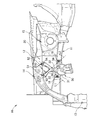
- the vehicle body 10 includes an engine mount support structure 20 at the front thereof.
- the engine mount support structure 20 includes a front side frame 11 extending in the longitudinal direction of the vehicle body, an upper member 12 that is juxtaposed on the outside of the front side frame 11 and curved upward toward the rear of the vehicle body, and the front side frame 11. And an engine mount 30 attached to the upper member 12.
- the vehicle body 10 further includes a front bulkhead 13 provided inside the front end of the front side frame 11, a front bulkhead upper support 14 that supports the upper part of the front bulkhead 13 on the upper member 17, and a front side frame in the vehicle longitudinal direction. 11 and a damper house 15 provided between the upper member 12 and the upper member 12.
- 1 is a support structure for an engine mount 30 that is supported by the front side frame 11 and the upper member 12 and supports an engine (not shown).
- the front side frame 11 is formed of a steel plate, and a frame main body 16 having a U-shaped cross section as shown in FIG. 8 and an opening formed of the steel plate and facing the outer side in the vehicle width direction are closed. It consists of a frame lid (lid member) 17 and forms a closed cross section.
- the front side frame 11 has a frame side front coupling portion 18 and a frame side rear coupling portion 19 that support the engine mount 30.
- the upper member 12 is juxtaposed on the outer side in the vehicle width direction of the front side frame 11, and is curved upward toward the rear of the vehicle body.
- the upper member 12 is formed of a steel plate, and a member main body 41 having a U-shaped cross section as shown in FIG. 4 and a member lid (cover member) formed of a steel plate and closing the opening of the member main body 51. ) 42 and has a closed cross-sectional structure.
- the upper member 12 has a member-side front coupling portion 51 and a member-side rear coupling portion 52 for attaching the mounting bracket 50 that supports the engine mount 30.
- the front bulkhead upper support 14 has a U-shaped cross section including an upper wall 14a, an inner wall 14b, and an outer wall 14c.
- the front bulkhead upper support 14 connects the middle of the upper member 12 and the upper part of the front bulkhead 13.
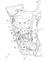
- the engine mount 30 includes an engine mount main body 31 (see FIG. 2), an upper support portion 32 provided on the upper side of the engine mount main body 31 and supported on the upper member 12 side via the mounting bracket 50, and the engine mount main body 31.
- a lower front support portion 33 provided in front of the lower portion and supported by the frame side front coupling portion 18 of the front side frame 11, and a frame side rear coupling portion 19 provided in the lower rear of the engine mount main body 31.
- a lower rear support portion 34 supported by the upper portion.
- the mounting bracket 50 is formed in a V shape.
- the mounting bracket 50 includes a vertical front mounting portion 53 and a rear mounting portion 54 that are respectively mounted on the member side front coupling portion 51 and the member side rear coupling portion 52 of the upper member 12, and a horizontal inner mounting portion to which the upper support portion 32 is mounted. 55 and a flange (bending portion) 56 that is formed over the entire circumference except the inner side in the vehicle width direction of the inner mounting portion 55 and increases the strength and rigidity of the mounting bracket 50.
- the front mounting portion 53 and the rear mounting portion 54 are provided with flanges 56.
- the upper support portion 32 of the engine mount 30 is supported by the upper member 12 via the front mounting portion 53 and the rear mounting portion 54 of the V-shaped mounting bracket 50. Therefore, the inner attachment portion 55 to which the upper support portion 32 is attached does not swing in the longitudinal direction of the vehicle body. Thereby, the support strength of the upper support part 32 of the engine mount 30 in the vehicle body front-rear direction can be improved.
- the inner mounting portion 55 does not swing in the vehicle width direction. Thereby, the support strength to the vehicle width direction of the upper support part 32 of the engine mount 30 can be improved. Therefore, even if a large engine swing occurs immediately after the start of the vehicle, the engine vibration can be suppressed and the sound pressure level in the passenger compartment can be reduced. As a result, it is possible to improve the quietness immediately after starting the vehicle. Furthermore, a change in sound pressure level when the vehicle is accelerated can be reduced.
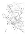
- a line connecting the frame-side front connecting portion 18 and the member-side rear connecting portion 52 is a first diagonal line L1
- a line connecting the frame-side rear connecting portion 19 and the member-side front connecting portion 51 is The second diagonal line L2.
- the parts of the front side frame 11 and the upper member 12 on the first and second diagonal lines L1 and L2 are set to have higher strength than the other parts. That is, the front side frame 11 is provided with a frame side front coupling portion 18 and a frame side rear coupling portion 19 that support the engine mount 30, and the upper member 12 has a member side on which a mounting bracket 50 that supports the engine mount 30 is attached. A front coupling portion 51 and a member side rear coupling portion 52 are provided.
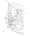
- the member-side front coupling portion 51 includes a color nut 61 into which a bolt (not shown) for fixing the front mounting portion of the mounting bracket 50 is screwed, and a partition wall (bracket member) 62.
- the partition wall 62 includes a bracket part 63 and a bulkhead part 64.
- the bracket part 63 and the bulkhead part 64 support the collar nut 61 on the upper member 12 and the front bulkhead upper support 14.
- the member side front coupling portion 51 is a support portion of a bulkhead structure with a collar nut.
- the collar nut 61 has a cylindrical portion 61b in which an internal thread 61a is formed, and a collar flange portion 61c that comes into contact with the front bulkhead upper support 14.
- the partition wall (bracket member) 62 is formed in a semi-cylindrical shape, and is formed on the coupling portion 65 to which the cylindrical portion 61 b of the collar nut 61 is coupled, and the bracket portion 63, and the inner wall 12 b of the upper member 12 and the front bulkhead upper support 14.
- the bracket portion 63 and the collar nut 61 extend in a direction (vehicle width direction) in which an input from the mounting bracket 50 acts.
- the bracket portion 63 is set in a direction to buckle with respect to the input from the mounting bracket 50.
- the outer front flange 63 b and the outer rear flange 63 c are coupled to both the upper member 12 and the front bulkhead upper support 14, so that input from the engine mount 30 It is distributed to both of the bulkhead upper support 14 and the support strength of the engine mount 30 is improved. Further, the outer front flange 63b and the outer rear flange 63c are coupled to both the upper member 12 and the front bulkhead upper support 14, whereby deformation of the front bulkhead upper support 14 can be suppressed.
- the member-side rear coupling portion 52 includes a collar nut 70 into which a bolt (not shown) for fixing the rear mounting portion 54 of the mounting bracket 50 (FIG. 3) is screwed, and the collar nut 70 is connected to the upper member 12 and It consists of a partition wall (bulk head) 71 supported by the front bulkhead upper support 14.
- the member side rear coupling portion 52 is a support portion of a bulkhead structure with a collar nut.
- the color nut 70 has the same configuration as the color nut 61 (FIG. 6).
- the partition wall 71 is formed in a semi-cylindrical shape on the partition body 72, and is formed on the partition body 72, and is coupled to the front bulkhead upper support 14.
- An upper flange 74 and a lower flange 75 formed on the partition wall main body 72 and coupled to the upper member 12 are provided.
- the frame-side front coupling portion 18 includes a collar nut 81 into which a bolt (not shown) for fixing the lower front support portion 33 (FIG. 1) is screwed, and the collar nut 81 is connected to the front side frame. 11 and a partition wall (front bracket) 82 that is supported by the motor 11.
- the collar nut 81 has substantially the same configuration as the collar nut 61 shown in FIG.
- the partition wall (front bracket) 82 is formed in a partition wall body (partition portion) 83, a semi-cylindrical shape formed on the partition wall body 83, the collar nut 81 is coupled to the partition wall body 83, and extends from the partition wall body 83.
- the main body has an inner joint 87 extending from 83 and joined to the frame main body 16.
- the frame-side rear coupling portion 19 includes a collar nut 91 into which a bolt (not shown) for fixing the lower rear support portion 34 (FIG. 1) is screwed, and a partition wall (rear bracket) 92 that supports the collar nut 91 on the front side frame 11. It consists of.
- the color nut 91 has substantially the same configuration as the color nut 61 shown in FIG.
- the partition wall (rear bracket) 92 includes a partition wall body (partition portion) 93, a coupling portion 94 formed in a semi-cylindrical shape on the partition wall body 93 and coupled with the color nut 91, and extends from the partition wall body 93.
- An inner joint 97 extending from the main body 93 and joined to the frame main body 16.
- the engine mount 30 includes an engine mount main body 31 that supports the engine, an upper support portion 32 that supports the upper portion of the engine mount main body 31, a lower front support portion 33 that supports the lower front of the engine mount main body 31, and an engine mount.
- a lower rear support portion 34 that supports the lower rear of the main body 31 is provided.
- the lower front support portion 33 and the lower rear support portion 34 of the engine mount 30 are attached to the frame side front coupling portion 18 and the frame side rear coupling portion 19 formed in the front-rear direction of the front side frame 11.
- the upper support portion 32 is supported by the upper member 12 via the mounting bracket 50.
- the mounting bracket 50 has a front mounting portion 53 and a rear mounting portion 54 which are respectively mounted on the member side front coupling portion 51 and the member side rear coupling portion 52 of the upper member 12 and an inner mounting portion 55 to which the upper support portion 32 is mounted. Since it is formed in a letter shape, the support strength of the engine mount 30 can be improved. As a result, engine vibration can be reduced, and the quietness of the passenger compartment can be improved.
- the line connecting the frame-side front coupling portion 18 and the member-side rear coupling portion 52 is the first diagonal line L1, and the frame-side rear coupling is performed.
- a line connecting the portion 19 and the member side front coupling portion 51 is defined as a second diagonal line L2.
- the portions of the front side frame 11 and the upper member 12 on the first and second diagonal lines L1 and L2 are set to have higher strength than the other portions, so that the vehicle width direction and the vehicle body longitudinal direction are set. With respect to both directions, the support strength of the engine mount 30 can be improved.
- the front bulkhead 13 is provided inside the front end of the front side frame 11.
- a front bulkhead upper support 14 that supports the upper portion of the front bulkhead 13 is provided on the upper member 12. Since the member side front coupling portion 51 is coupled to the front bulkhead upper support 14 as well, the support strength of the upper portion of the engine mount 30 is improved.
- the member-side front coupling portion 51 has a partition wall 62 coupled to the upper wall 14a of the front bulkhead upper support 14. For this reason, since the partition wall 62 is coupled in the shear direction of the partition wall 62 in the vehicle width direction and the vehicle body longitudinal direction, the support strength in the vehicle width direction and the vehicle body longitudinal direction is increased.
- the V-shaped mounting bracket 50 has a flange (bending portion) 56 that increases the strength of the mounting bracket 50 on the outer periphery, and therefore, the member-side front coupling portion 51 and the member-side rear coupling portion. 52 is reinforced, and the support strength of the mounting bracket 50 can be improved.
- the member-side front coupling portion 51 is disposed on the upper surface 46 a of the curved portion 46 of the upper member 12.
- the member side rear coupling portion 52 is disposed in the curved portion 46 of the upper member 12. For this reason, it becomes possible to arrange
- the mounting bracket 50 has a flange 56 that increases the strength and rigidity of the mounting bracket 50 over the entire circumference except for the inner width of the inner mounting portion 55.
- a flange that increases the strength and rigidity may be formed over the entire circumference including the inner side of the inner mounting portion 55 as appropriate.
- the engine mount support structure according to the present invention is suitable for use in a passenger car such as a sedan or a wagon type.
- SYMBOLS 10 Vehicle body, 11 ... Front side frame, 12 ... Upper member, 13 ... Front bulkhead, 14 ... Front bulkhead upper support, 14a ... Upper wall, 18 ... Frame side front coupling part, 19 ... Frame side rear coupling part, 30 ... Engine mount 31 ... Engine mount body 32 ... Upper support part 33 ... Lower front support part 34 ... Lower rear support part 50 ... Mounting bracket 51 ... Member side front joint part 52 ... Member side rear joint part , 53 ... front mounting part, 54 ... rear mounting part, 55 ... inner mounting part, 56 ... flange (bending part), 62 ... partition wall (bulk head), L1 ... first diagonal line, L2 ... second diagonal line.
Abstract
Description
Claims (6)
- エンジンマウント支持構造であって、
車体の前後方向に延びているフロントサイドフレームと、
前記フロントサイドフレームの車幅方向外側に配置され、車体後方に向けて上方に湾曲されたアッパメンバと、
前記フロントサイドフレームおよび前記アッパメンバ間に取り付けられたエンジンマウントと、
を具備しており、
前記エンジンマウントは、エンジンマウント本体と、該エンジンマウント本体の上部を支持する上部支持部と、前記エンジンマウント本体の下部前方を支持する下部前支持部と、前記エンジンマウント本体の下部後方を支持する下部後支持部とを備え、
前記下部前支持部及び下部後支持部は、前記フロントサイドフレームの前記車体の前後方向に形成されるフレーム側前結合部及びフレーム側後結合部に取付けられ、前記上部支持部は、前記アッパメンバに取付けられた取付ブラケットで支持されており、
前記取付ブラケットは、前記アッパメンバのメンバ側前結合部及びメンバ側後結合部にそれぞれ取付けられる前取付部及び後取付部と、前記上部支持部が取付けられる内取付部を有するV字状に形成されていることを特徴とするエンジンマウント支持構造。 - 前記フレーム側前結合部と前記メンバ側後結合部とを結ぶ線を第1の対角線とし、前記フレーム側後結合部とメンバ側前結合部とを結ぶ線を第2の対角線とすると、前記第1及び第2の対角線上の前記フロントサイドフレーム及び前記アッパメンバの部位は、それぞれの他の部位よりも強度が大きく設定されていることを特徴とする請求項1記載のエンジンマウント支持構造。
- 前記フロントサイドフレームは、前端内側に設けられたフロントバルクを有しており、前記フロントバルクヘッドの上部を支持するフロントバルクヘッドアッパサポートは、前記アッパメンバにが設けられており、前記メンバ側前結合部は、前記フロントバルクヘッドアッパサポートにも結合していることを特徴とする請求項1に記載のエンジンマウント支持構造。
- 前記メンバ側前結合部は、前記フロントバルクヘッドアッパサポートの上壁に結合される隔壁を有していることを特徴とする請求項1に載のエンジンマウント支持構造。
- 前記V字形状の取付ブラケットは、外周に該取付ブラケットの強度を強くするフランジを有することを特徴とする請求項1にエンジンマウント支持構造。
- 前記メンバ側前結合部は、前記アッパメンバの湾曲部の上面に配置され、前記メンバ側後結合部は、前記アッパメンバの湾曲部内に配置されていることを特徴とする請求項1に記載のエンジンマウント支持構造。
Priority Applications (4)
| Application Number | Priority Date | Filing Date | Title |
|---|---|---|---|
| EP11814377.5A EP2602142B1 (en) | 2010-08-05 | 2011-06-21 | Engine mount support structure |
| CN201180038136.6A CN103068607B (zh) | 2010-08-05 | 2011-06-21 | 发动机架支承构造 |
| US13/813,979 US8870273B2 (en) | 2010-08-05 | 2011-06-21 | Engine mount support structure |
| JP2012527635A JP5539523B2 (ja) | 2010-08-05 | 2011-06-21 | エンジンマウント支持構造 |
Applications Claiming Priority (2)
| Application Number | Priority Date | Filing Date | Title |
|---|---|---|---|
| JP2010176604 | 2010-08-05 | ||
| JP2010-176604 | 2010-08-05 |
Publications (1)
| Publication Number | Publication Date |
|---|---|
| WO2012017747A1 true WO2012017747A1 (ja) | 2012-02-09 |
Family
ID=45559260
Family Applications (1)
| Application Number | Title | Priority Date | Filing Date |
|---|---|---|---|
| PCT/JP2011/064122 WO2012017747A1 (ja) | 2010-08-05 | 2011-06-21 | エンジンマウント支持構造 |
Country Status (5)
| Country | Link |
|---|---|
| US (1) | US8870273B2 (ja) |
| EP (1) | EP2602142B1 (ja) |
| JP (1) | JP5539523B2 (ja) |
| CN (1) | CN103068607B (ja) |
| WO (1) | WO2012017747A1 (ja) |
Cited By (2)
| Publication number | Priority date | Publication date | Assignee | Title |
|---|---|---|---|---|
| WO2014119363A1 (ja) * | 2013-01-30 | 2014-08-07 | 本田技研工業株式会社 | 車体前部構造 |
| JP2019051914A (ja) * | 2017-09-19 | 2019-04-04 | トヨタ自動車株式会社 | 車両前部構造及び車両用ブラケット |
Families Citing this family (6)
| Publication number | Priority date | Publication date | Assignee | Title |
|---|---|---|---|---|
| EP2679472B1 (en) * | 2011-02-23 | 2015-12-09 | Honda Motor Co., Ltd. | Structure for front portion of automobile body |
| JP6197241B2 (ja) * | 2015-10-22 | 2017-09-20 | 本田技研工業株式会社 | 車体前部構造 |
| JP6597730B2 (ja) | 2017-07-14 | 2019-10-30 | マツダ株式会社 | 車両の前部車体構造 |
| JP6583358B2 (ja) * | 2017-07-26 | 2019-10-02 | マツダ株式会社 | 車両のパワートレインマウント構造 |
| JP6451805B1 (ja) * | 2017-08-22 | 2019-01-16 | マツダ株式会社 | エンジンの保温構造 |
| US10813270B2 (en) | 2017-09-14 | 2020-10-27 | Cnh Industrial America Llc | Shear block equipment mounting system for an agricultural product applicator |
Citations (5)
| Publication number | Priority date | Publication date | Assignee | Title |
|---|---|---|---|---|
| JP2003002240A (ja) * | 2001-06-27 | 2003-01-08 | Nissan Motor Co Ltd | パワーユニットの支持ブラケット |
| JP2003322197A (ja) * | 2002-05-07 | 2003-11-14 | Toyo Tire & Rubber Co Ltd | 防振装置 |
| JP2004299595A (ja) * | 2003-03-31 | 2004-10-28 | Nissan Motor Co Ltd | 車両用エンジンマウントブラケット |
| JP2005112175A (ja) * | 2003-10-08 | 2005-04-28 | Honda Motor Co Ltd | 自動車の前部車体構造 |
| JP2006213245A (ja) * | 2005-02-04 | 2006-08-17 | Toyota Motor Corp | 車両前部構造 |
Family Cites Families (15)
| Publication number | Priority date | Publication date | Assignee | Title |
|---|---|---|---|---|
| JPH0746601Y2 (ja) * | 1988-10-05 | 1995-10-25 | マツダ株式会社 | 車両の前部車体構造 |
| JP3688526B2 (ja) * | 1999-08-26 | 2005-08-31 | 本田技研工業株式会社 | 車両の前部構造 |
| DE10023193B4 (de) * | 2000-05-11 | 2006-10-26 | Dr.Ing.H.C. F. Porsche Ag | Fahrzeugaufbau für einen Vorderwagen eines Kraftfahrzeugs |
| JP3775280B2 (ja) * | 2001-10-31 | 2006-05-17 | 日産自動車株式会社 | 車体前部構造 |
| JP3632666B2 (ja) * | 2002-02-01 | 2005-03-23 | 日産自動車株式会社 | 車体前部構造 |
| JP4144385B2 (ja) * | 2003-03-12 | 2008-09-03 | 三菱自動車工業株式会社 | 自動車の車室前部の結合構造 |
| JP4168826B2 (ja) * | 2003-05-09 | 2008-10-22 | 日産自動車株式会社 | 自動車のエンジンマウント構造 |
| JP4751620B2 (ja) * | 2005-02-04 | 2011-08-17 | 日産自動車株式会社 | 車体の前部構造 |
| JP4408818B2 (ja) | 2005-02-14 | 2010-02-03 | 本田技研工業株式会社 | マウント装置の取付構造 |
| DE102005014938B4 (de) * | 2005-04-01 | 2019-07-25 | Man Truck & Bus Ag | Verbesserter Motorhalter für ein Nutzfahrzeug |
| JP4233053B2 (ja) * | 2006-04-27 | 2009-03-04 | 本田技研工業株式会社 | 車体前部構造 |
| JP2008168792A (ja) * | 2007-01-12 | 2008-07-24 | Fuji Heavy Ind Ltd | 自動車のサスペンションクロスメンバ構造 |
| US7695052B2 (en) * | 2007-03-30 | 2010-04-13 | Ford Global Technologies, Llc | Front rail having controlled thickness for energy absorption |
| US7828330B2 (en) * | 2008-03-17 | 2010-11-09 | Honda Motor Co., Ltd. | Vehicle front body structure |
| JP5504820B2 (ja) * | 2009-10-26 | 2014-05-28 | マツダ株式会社 | 車両の前部車体構造 |
-
2011
- 2011-06-21 JP JP2012527635A patent/JP5539523B2/ja not_active Expired - Fee Related
- 2011-06-21 CN CN201180038136.6A patent/CN103068607B/zh active Active
- 2011-06-21 WO PCT/JP2011/064122 patent/WO2012017747A1/ja active Application Filing
- 2011-06-21 EP EP11814377.5A patent/EP2602142B1/en not_active Not-in-force
- 2011-06-21 US US13/813,979 patent/US8870273B2/en active Active
Patent Citations (5)
| Publication number | Priority date | Publication date | Assignee | Title |
|---|---|---|---|---|
| JP2003002240A (ja) * | 2001-06-27 | 2003-01-08 | Nissan Motor Co Ltd | パワーユニットの支持ブラケット |
| JP2003322197A (ja) * | 2002-05-07 | 2003-11-14 | Toyo Tire & Rubber Co Ltd | 防振装置 |
| JP2004299595A (ja) * | 2003-03-31 | 2004-10-28 | Nissan Motor Co Ltd | 車両用エンジンマウントブラケット |
| JP2005112175A (ja) * | 2003-10-08 | 2005-04-28 | Honda Motor Co Ltd | 自動車の前部車体構造 |
| JP2006213245A (ja) * | 2005-02-04 | 2006-08-17 | Toyota Motor Corp | 車両前部構造 |
Cited By (6)
| Publication number | Priority date | Publication date | Assignee | Title |
|---|---|---|---|---|
| WO2014119363A1 (ja) * | 2013-01-30 | 2014-08-07 | 本田技研工業株式会社 | 車体前部構造 |
| CN104968558A (zh) * | 2013-01-30 | 2015-10-07 | 本田技研工业株式会社 | 车身前部构造 |
| JP5887432B2 (ja) * | 2013-01-30 | 2016-03-16 | 本田技研工業株式会社 | 車体前部構造 |
| US9505295B2 (en) | 2013-01-30 | 2016-11-29 | Honda Motor Co., Ltd. | Structure for front section of vehicle body |
| CN104968558B (zh) * | 2013-01-30 | 2016-12-14 | 本田技研工业株式会社 | 车身前部构造 |
| JP2019051914A (ja) * | 2017-09-19 | 2019-04-04 | トヨタ自動車株式会社 | 車両前部構造及び車両用ブラケット |
Also Published As
| Publication number | Publication date |
|---|---|
| EP2602142A4 (en) | 2014-02-19 |
| JP5539523B2 (ja) | 2014-07-02 |
| CN103068607A (zh) | 2013-04-24 |
| US20130140852A1 (en) | 2013-06-06 |
| US8870273B2 (en) | 2014-10-28 |
| CN103068607B (zh) | 2015-09-09 |
| EP2602142B1 (en) | 2015-04-15 |
| EP2602142A1 (en) | 2013-06-12 |
| JPWO2012017747A1 (ja) | 2013-10-03 |
Similar Documents
| Publication | Publication Date | Title |
|---|---|---|
| JP5539523B2 (ja) | エンジンマウント支持構造 | |
| JP5488699B2 (ja) | 車体前部構造 | |
| WO2013094190A1 (ja) | 自動車のフロントサブフレーム構造 | |
| US8967671B2 (en) | Bolting structure of sub-frame | |
| US20150360726A1 (en) | Vehicle front portion structure | |
| WO2018207687A1 (ja) | 車両の後部車体構造 | |
| JP5870673B2 (ja) | 自動車のフロントサブフレーム構造 | |
| JP2010105585A (ja) | 自動車のステアリング支持構造 | |
| JP2020163957A (ja) | サブフレーム構造 | |
| JP2005138652A (ja) | 車両用サスペンションメンバの補強構造 | |
| JP2014151657A (ja) | 車両の前部車体構造 | |
| JP4897592B2 (ja) | ステアリングコラム支持構造 | |
| JP2010247599A (ja) | 車体前部構造 | |
| WO2018030472A1 (ja) | ステアリングメンバ | |
| JP2000072029A (ja) | 車両用サブフレーム | |
| JP5968635B2 (ja) | 自動車の車体前部構造 | |
| JP5235156B2 (ja) | 車体後部構造 | |
| JP5496727B2 (ja) | 自動車の前部車体構造 | |
| JP2010111257A (ja) | 車両のルーフ構造 | |
| JP4853914B2 (ja) | 自動車の車体前部構造 | |
| JP4853106B2 (ja) | 自動車の前部車体構造 | |
| JP6603578B2 (ja) | サスペンションメンバの補強構造 | |
| JP7347115B2 (ja) | 車両カウル部構造 | |
| JP7129749B2 (ja) | 車両構造 | |
| JP2000072032A (ja) | 車両用フロントメンバ |
Legal Events
| Date | Code | Title | Description |
|---|---|---|---|
| WWE | Wipo information: entry into national phase |
Ref document number: 201180038136.6 Country of ref document: CN |
|
| 121 | Ep: the epo has been informed by wipo that ep was designated in this application |
Ref document number: 11814377 Country of ref document: EP Kind code of ref document: A1 |
|
| WWE | Wipo information: entry into national phase |
Ref document number: 2012527635 Country of ref document: JP |
|
| WWE | Wipo information: entry into national phase |
Ref document number: 2011814377 Country of ref document: EP |
|
| WWE | Wipo information: entry into national phase |
Ref document number: 13813979 Country of ref document: US |
|
| NENP | Non-entry into the national phase |
Ref country code: DE |