WO2012014835A1 - 焼成用ラック - Google Patents
焼成用ラック Download PDFInfo
- Publication number
- WO2012014835A1 WO2012014835A1 PCT/JP2011/066826 JP2011066826W WO2012014835A1 WO 2012014835 A1 WO2012014835 A1 WO 2012014835A1 JP 2011066826 W JP2011066826 W JP 2011066826W WO 2012014835 A1 WO2012014835 A1 WO 2012014835A1
- Authority
- WO
- WIPO (PCT)
- Prior art keywords
- setter
- sic
- rack
- firing
- holding means
- Prior art date
- Legal status (The legal status is an assumption and is not a legal conclusion. Google has not performed a legal analysis and makes no representation as to the accuracy of the status listed.)
- Ceased
Links
Images

Classifications
-
- F—MECHANICAL ENGINEERING; LIGHTING; HEATING; WEAPONS; BLASTING
- F27—FURNACES; KILNS; OVENS; RETORTS
- F27D—DETAILS OR ACCESSORIES OF FURNACES, KILNS, OVENS OR RETORTS, IN SO FAR AS THEY ARE OF KINDS OCCURRING IN MORE THAN ONE KIND OF FURNACE
- F27D5/00—Supports, screens or the like for the charge within the furnace
- F27D5/0031—Treatment baskets for ceramic articles
-
- B—PERFORMING OPERATIONS; TRANSPORTING
- B22—CASTING; POWDER METALLURGY
- B22F—WORKING METALLIC POWDER; MANUFACTURE OF ARTICLES FROM METALLIC POWDER; MAKING METALLIC POWDER; APPARATUS OR DEVICES SPECIALLY ADAPTED FOR METALLIC POWDER
- B22F3/00—Manufacture of workpieces or articles from metallic powder characterised by the manner of compacting or sintering; Apparatus specially adapted therefor ; Presses and furnaces
- B22F3/003—Apparatus, e.g. furnaces
-
- C—CHEMISTRY; METALLURGY
- C04—CEMENTS; CONCRETE; ARTIFICIAL STONE; CERAMICS; REFRACTORIES
- C04B—LIME, MAGNESIA; SLAG; CEMENTS; COMPOSITIONS THEREOF, e.g. MORTARS, CONCRETE OR LIKE BUILDING MATERIALS; ARTIFICIAL STONE; CERAMICS; REFRACTORIES; TREATMENT OF NATURAL STONE
- C04B35/00—Shaped ceramic products characterised by their composition; Ceramics compositions; Processing powders of inorganic compounds preparatory to the manufacturing of ceramic products
- C04B35/515—Shaped ceramic products characterised by their composition; Ceramics compositions; Processing powders of inorganic compounds preparatory to the manufacturing of ceramic products based on non-oxide ceramics
- C04B35/56—Shaped ceramic products characterised by their composition; Ceramics compositions; Processing powders of inorganic compounds preparatory to the manufacturing of ceramic products based on non-oxide ceramics based on carbides or oxycarbides
- C04B35/565—Shaped ceramic products characterised by their composition; Ceramics compositions; Processing powders of inorganic compounds preparatory to the manufacturing of ceramic products based on non-oxide ceramics based on carbides or oxycarbides based on silicon carbide
- C04B35/573—Shaped ceramic products characterised by their composition; Ceramics compositions; Processing powders of inorganic compounds preparatory to the manufacturing of ceramic products based on non-oxide ceramics based on carbides or oxycarbides based on silicon carbide obtained by reaction sintering or recrystallisation
-
- F—MECHANICAL ENGINEERING; LIGHTING; HEATING; WEAPONS; BLASTING
- F27—FURNACES; KILNS; OVENS; RETORTS
- F27D—DETAILS OR ACCESSORIES OF FURNACES, KILNS, OVENS OR RETORTS, IN SO FAR AS THEY ARE OF KINDS OCCURRING IN MORE THAN ONE KIND OF FURNACE
- F27D5/00—Supports, screens or the like for the charge within the furnace
- F27D5/0037—Supports specially adapted for semi-conductors
-
- B—PERFORMING OPERATIONS; TRANSPORTING
- B22—CASTING; POWDER METALLURGY
- B22F—WORKING METALLIC POWDER; MANUFACTURE OF ARTICLES FROM METALLIC POWDER; MAKING METALLIC POWDER; APPARATUS OR DEVICES SPECIALLY ADAPTED FOR METALLIC POWDER
- B22F3/00—Manufacture of workpieces or articles from metallic powder characterised by the manner of compacting or sintering; Apparatus specially adapted therefor ; Presses and furnaces
- B22F3/10—Sintering only
- B22F2003/1042—Sintering only with support for articles to be sintered
-
- C—CHEMISTRY; METALLURGY
- C04—CEMENTS; CONCRETE; ARTIFICIAL STONE; CERAMICS; REFRACTORIES
- C04B—LIME, MAGNESIA; SLAG; CEMENTS; COMPOSITIONS THEREOF, e.g. MORTARS, CONCRETE OR LIKE BUILDING MATERIALS; ARTIFICIAL STONE; CERAMICS; REFRACTORIES; TREATMENT OF NATURAL STONE
- C04B2235/00—Aspects relating to ceramic starting mixtures or sintered ceramic products
- C04B2235/02—Composition of constituents of the starting material or of secondary phases of the final product
- C04B2235/30—Constituents and secondary phases not being of a fibrous nature
- C04B2235/38—Non-oxide ceramic constituents or additives
- C04B2235/3852—Nitrides, e.g. oxynitrides, carbonitrides, oxycarbonitrides, lithium nitride, magnesium nitride
- C04B2235/3873—Silicon nitrides, e.g. silicon carbonitride, silicon oxynitride
-
- C—CHEMISTRY; METALLURGY
- C04—CEMENTS; CONCRETE; ARTIFICIAL STONE; CERAMICS; REFRACTORIES
- C04B—LIME, MAGNESIA; SLAG; CEMENTS; COMPOSITIONS THEREOF, e.g. MORTARS, CONCRETE OR LIKE BUILDING MATERIALS; ARTIFICIAL STONE; CERAMICS; REFRACTORIES; TREATMENT OF NATURAL STONE
- C04B2235/00—Aspects relating to ceramic starting mixtures or sintered ceramic products
- C04B2235/02—Composition of constituents of the starting material or of secondary phases of the final product
- C04B2235/30—Constituents and secondary phases not being of a fibrous nature
- C04B2235/42—Non metallic elements added as constituents or additives, e.g. sulfur, phosphor, selenium or tellurium
- C04B2235/428—Silicon
-
- C—CHEMISTRY; METALLURGY
- C04—CEMENTS; CONCRETE; ARTIFICIAL STONE; CERAMICS; REFRACTORIES
- C04B—LIME, MAGNESIA; SLAG; CEMENTS; COMPOSITIONS THEREOF, e.g. MORTARS, CONCRETE OR LIKE BUILDING MATERIALS; ARTIFICIAL STONE; CERAMICS; REFRACTORIES; TREATMENT OF NATURAL STONE
- C04B2235/00—Aspects relating to ceramic starting mixtures or sintered ceramic products
- C04B2235/70—Aspects relating to sintered or melt-casted ceramic products
- C04B2235/72—Products characterised by the absence or the low content of specific components, e.g. alkali metal free alumina ceramics
-
- C—CHEMISTRY; METALLURGY
- C04—CEMENTS; CONCRETE; ARTIFICIAL STONE; CERAMICS; REFRACTORIES
- C04B—LIME, MAGNESIA; SLAG; CEMENTS; COMPOSITIONS THEREOF, e.g. MORTARS, CONCRETE OR LIKE BUILDING MATERIALS; ARTIFICIAL STONE; CERAMICS; REFRACTORIES; TREATMENT OF NATURAL STONE
- C04B2235/00—Aspects relating to ceramic starting mixtures or sintered ceramic products
- C04B2235/70—Aspects relating to sintered or melt-casted ceramic products
- C04B2235/74—Physical characteristics
- C04B2235/77—Density
-
- C—CHEMISTRY; METALLURGY
- C04—CEMENTS; CONCRETE; ARTIFICIAL STONE; CERAMICS; REFRACTORIES
- C04B—LIME, MAGNESIA; SLAG; CEMENTS; COMPOSITIONS THEREOF, e.g. MORTARS, CONCRETE OR LIKE BUILDING MATERIALS; ARTIFICIAL STONE; CERAMICS; REFRACTORIES; TREATMENT OF NATURAL STONE
- C04B2235/00—Aspects relating to ceramic starting mixtures or sintered ceramic products
- C04B2235/70—Aspects relating to sintered or melt-casted ceramic products
- C04B2235/80—Phases present in the sintered or melt-cast ceramic products other than the main phase
-
- C—CHEMISTRY; METALLURGY
- C04—CEMENTS; CONCRETE; ARTIFICIAL STONE; CERAMICS; REFRACTORIES
- C04B—LIME, MAGNESIA; SLAG; CEMENTS; COMPOSITIONS THEREOF, e.g. MORTARS, CONCRETE OR LIKE BUILDING MATERIALS; ARTIFICIAL STONE; CERAMICS; REFRACTORIES; TREATMENT OF NATURAL STONE
- C04B2235/00—Aspects relating to ceramic starting mixtures or sintered ceramic products
- C04B2235/70—Aspects relating to sintered or melt-casted ceramic products
- C04B2235/96—Properties of ceramic products, e.g. mechanical properties such as strength, toughness, wear resistance
- C04B2235/9607—Thermal properties, e.g. thermal expansion coefficient
- C04B2235/9623—Ceramic setters properties
-
- C—CHEMISTRY; METALLURGY
- C04—CEMENTS; CONCRETE; ARTIFICIAL STONE; CERAMICS; REFRACTORIES
- C04B—LIME, MAGNESIA; SLAG; CEMENTS; COMPOSITIONS THEREOF, e.g. MORTARS, CONCRETE OR LIKE BUILDING MATERIALS; ARTIFICIAL STONE; CERAMICS; REFRACTORIES; TREATMENT OF NATURAL STONE
- C04B2235/00—Aspects relating to ceramic starting mixtures or sintered ceramic products
- C04B2235/70—Aspects relating to sintered or melt-casted ceramic products
- C04B2235/96—Properties of ceramic products, e.g. mechanical properties such as strength, toughness, wear resistance
- C04B2235/963—Surface properties, e.g. surface roughness
-
- F—MECHANICAL ENGINEERING; LIGHTING; HEATING; WEAPONS; BLASTING
- F27—FURNACES; KILNS; OVENS; RETORTS
- F27D—DETAILS OR ACCESSORIES OF FURNACES, KILNS, OVENS OR RETORTS, IN SO FAR AS THEY ARE OF KINDS OCCURRING IN MORE THAN ONE KIND OF FURNACE
- F27D5/00—Supports, screens or the like for the charge within the furnace
- F27D2005/0081—Details
Definitions
- the present invention mainly relates to a rack for firing suitable for multistage firing of electronic ceramic elements.
- an electronic ceramic element is obtained by adding a sintering aid and a molding aid to a ceramic fine powder as a main raw material and mixing them, and then forming an unfired element by molding.
- the unfired element is formed into a ceramic plate called a setter. It is mounted and placed in a firing furnace, and is fired and manufactured while controlling the interior of the furnace at a predetermined temperature and atmospheric conditions.
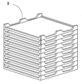
- the setter is usually used by being stacked in a plurality of stages, and as a structure for forming a space between the setters stacked in a plurality of stages, for example, as shown in FIG.
- a structure (Patent Document 1) is disclosed in which a flat plate-like setter is stacked on a tray.
- a structure is also known in which a peripheral wall portion formed so as to ensure strength enough to withstand stacking is formed on the upper surface periphery of the setter itself to form a dish shape, and this dish-like setter is laminated (Patent Document 2). ).
- an object of the present invention is to solve the above-mentioned conventional problems, and to provide a firing rack that is excellent in energy efficiency and mass production efficiency when multi-stage firing of an electronic ceramic element and excellent in heat uniformity of each stage in multi-stage firing. Is to provide.
- the firing rack of the present invention made to solve the above-mentioned problems is a firing rack that holds a plurality of flat plate setters in multiple stages in the vertical direction by setter holding means, and the setter holding means has a structure of 0.
- the setter holding means is made of any material of Si—SiC containing 01 to 30% Si, recrystallized SiC, and Si 3 N 4 —SiC. Is held in an exposed state.
- the invention according to claim 2 is the firing rack according to claim 1, wherein the setter holding means includes a plurality of vertical columns provided with a setter holding mechanism, and a lower end support frame that supports a lower end of the vertical column.
- a vertical support that has an upper end support frame that supports the upper end of the vertical support, and the setter holding mechanism faces a plurality of recesses or protrusions formed on the inner surface of the vertical support, or a flat setter It is characterized in that it consists of at least one of the beams passed between, the vertical struts as claimed in claim 3, corner vertical struts constituting the vertical sides of the four corners, and You may make it consist of the intermediate
- the setter holding means comprises a frame-shaped flat plate member having a plurality of stacking protrusions in the peripheral portion, and holds the flat setter. It is characterized in that it is laminated in multiple stages.
- the setter holding means includes a pair of linear members arranged to face each other with a plurality of stacking protrusions, and upper portions of the stacking protrusions. It consists of beams spanned between concave surfaces, and is laminated in multiple stages in a state where a flat plate-like setter is held on these beams.
- the member constituting the setter holding means is made of Si-SiC containing 0.01 to 30% Si
- the chemical composition is SiC: 70 to 99%, Si: 1 to 30%
- SiC + Si is 100% and further contains Al: 0.01 to 0.2%, Fe: 0.01 to 0.2%, and Ca: 0.01 to 0.2%.
- the flat setter is also made of Si—SiC containing 0.01 to 30% of Si.
- the chemical composition is SiC: 99 to 100%, with SiC as 100%, further Al: 0.01 to 0.2%, Fe: It preferably contains 0.01 to 0.2% and Ca: 0.01 to 0.2%.
- the member constituting the setter holding means is made of Si 3 N 4 —SiC
- the chemical composition is SiC: 70-80%, Si 3 N 4 : 20-30%, and SiC + Si 3 N 4 is 100 Further, it is preferable to contain Al: 0.1 to 0.5%, Fe: 0.1 to 0.5%, and Ca: 0.01 to 0.2%.
- the firing rack of the present invention has a plurality of flat plate-like shapes by a setter holding means made of any material of Si—SiC containing 0.01 to 30% Si, recrystallized SiC, and Si 3 N 4 —SiC.
- the setter is held with 70 to 100% of the outer peripheral side surface exposed.
- the setter holding means made of these materials has a higher heat emissivity than the commonly used alumina and the like, and exposes 70 to 100% of the outer peripheral side surface of the flat plate setter.
- the atmosphere temperature in the furnace can be quickly transmitted to the upper electronic ceramic element. Therefore, it is excellent in the soaking
- the setter holding means made of these materials has a higher strength under high temperature conditions than that of generally used alumina or the like, and the size and weight can be reduced accordingly. Therefore, it is excellent in energy efficiency and mass production efficiency when the electronic ceramic element is fired in multiple stages.
- the firing rack according to the invention of claim 2 has a plurality of vertical struts and a lower end support frame that supports the lower end portions of the vertical struts. And a structure including a setter holding mechanism for holding a plurality of flat plate-like setters in multiple stages in the vertical direction, and having an upper end support frame that supports the upper end portion of the vertical column, and ensuring strength that can withstand stacking.
- the projecting portion formed as described above becomes unnecessary, and energy efficiency and mass production efficiency can be improved as compared with the conventional case.
- the entire lower surface of the lowermost setter contacts the furnace body directly or via a tray.
- an electronic ceramic element subjected to heat treatment with the lowermost setter has a lower product yield than an electronic ceramic element subjected to heat treatment at the upper stage, etc.
- the setter can be held more stably. Further, in particular, according to the configuration in which the beam is passed between the intermediate vertical columns, heat conduction is performed to the center portion of the setter at each stage through the beam, and therefore, it is affected by the heat conduction from the corner vertical column. It is possible to achieve soaking with the setter edge.
- the setter holding means is composed of a frame-like flat plate member provided with a plurality of stacking projections in the peripheral portion, and is configured to be laminated in multiple stages while holding the flat plate setter.
- the heat capacity of the setter holding means can be reduced to increase the energy efficiency and mass production efficiency when firing the electronic ceramic element in multiple stages.
- it is excellent in the contact property with the gas in a furnace, and is excellent in the soaking
- the setter holding means comprises a pair of linear members provided with a plurality of stacking protrusions and arranged opposite to each other, and a beam spanned between the upper concave surfaces of the stacking protrusions. Since the multi-layered structure in which the flat setter is held on these beams is used, the same effect as that of the invention of claim 4 can be obtained.
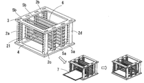
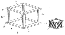
- the firing rack 1 of the present embodiment has a substantially cubic shape, and the setter holding means includes four corner vertical struts 2 constituting the vertical sides of the four corners, and the four corner vertical struts 2 (2a 2b, 2c, 2d), and a substantially lower-shaped lower end support frame 4 that supports the lower end portions of the four vertical support columns 2, and a substantially lower-shaped upper end support frame 3 that supports the upper end portions of the four vertical columns 2. Yes. As shown in FIG. 1, the firing rack 1 is used by inserting a flat setter 7.
- a horizontal groove portion 21 is formed on the inner side surface of each corner vertical support column 2 in parallel with the insertion direction of the flat plate-like setter 7 to constitute a setter holding mechanism.
- the flat setter 7 is inserted and held at the position of the horizontal groove 21.
- a plurality of the horizontal groove portions 21 are formed, and by holding a plurality of flat plate-like setters 7 in each horizontal groove portion 21, a multistage firing firing jig as shown in FIG. 2 can be configured.
- a firing jig for multi-stage firing by inserting a flat setter into the rack, compared to the conventional configuration in which the setters are stacked while forming a space at the protruding portion between each setter Therefore, energy efficiency and mass production efficiency can be improved.
- the form of the setter holding mechanism is not limited to the horizontal groove portion 21.
- the firing rack 1 includes intermediate vertical struts 5 (5a and 5b) arranged vertically between adjacent corner vertical struts (between 2a and 2b and between 2c and 2d), and a flat setter 7 It is provided in a pair at the facing position across.
- the pair of intermediate vertical struts (5a and 5b) has a plurality of horizontal hole portions 51 on each inner surface, and a beam 6 is formed between the horizontal hole portions 51 that form a pair at a facing position across the flat plate-like setter 7. Has been passed.
- the height of the beam 6 is arranged so as to support the central portion of the flat plate-like setter 7 held in each horizontal groove portion 21 from the lower surface.
- a setter can be hold
- heat conduction is performed to the center of the setter at each stage through the beam, it is possible to achieve a uniform temperature with the edge of the setter that is affected by heat conduction from the corner vertical column 2. it can.
- a baking rack 1 that does not include the intermediate vertical column 5 may be used.
- the setter holding mechanism is provided on the inner surface of the vertical column. From the formed horizontal grooves 21 By adopting the structure, the space in between the lower surface and the furnace of the lowermost setter is formed, it is possible to reduce the influence of heat conduction from the furnace body.
- the lower ends and the upper ends of the vertical support columns 2 and 5 are formed on the lower support frame 4 and the upper support frame 3, respectively.
- the inclination angle of the vertical column with respect to the lower end support frame is preferably 2 ° or less.
- the inclination angle is 2 ° or more, vibration during use increases, and there is a risk that the secret fired product may be damaged due to vibration accompanying conveyance in the furnace during firing. The problem can be effectively avoided.
- the heat to the setter constituting each stage Transmission becomes more uniform, and soaking can be achieved at each stage.
- the firing rack of the present invention is usually used under a high temperature condition of about 1300 to 1450 ° C. in an inert gas atmosphere. Therefore, in the present invention, the setter holding means is made of any material of Si—SiC containing 0.01 to 30% Si, recrystallized SiC, or Si 3 N 4 —SiC.
- Si-SiC is a material called Si-impregnated SiC in which Si particles are impregnated with Si.
- SiC As its chemical composition, SiC is 70 to 99%, Si is 1 to 30%, Al is 0.01 to 0.2%, Fe is 0.1 to 0.2%, and Fe is 0.1 to 0.2% as a trace component (SiC + Si is 100%). It is preferable to contain 01 to 0.2% and Ca to 0.01 to 0.2%. If the Si content exceeds 30%, the strength and the heat radiation rate are lowered, which is not preferable.
- the elastic modulus is 200-400 GPa
- the strength is 100-400 MPa
- the thermal conductivity at room temperature is 150-240 W / m ⁇ k
- the porosity is 1%.
- the following is preferable.
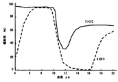
- the heat emissivity of the Si—SiC setter holding means is 80 to 100% at a wavelength of 8 ⁇ m, 20 to 40% at a wavelength of 12 ⁇ m, and 60 to 80% at a wavelength of 19 ⁇ m. It is preferable that The thermal emissivity can be defined by the chemical composition and the surface roughness.
- SiC is 70 to 99%, Si is 1 to 30%, and the trace component is external.
- the heat radiation rate is realized.
- the broken line of FIG. 4 is a heat radiation rate at the time of employ
- the heat emissivity of each component (2, 5, 3, 4) is increased by using Si-SiC instead of alumina which is generally used as a main component of a conventional setter. The radiant heat from each constituent member (2, 3, 4) in the furnace is effectively used to enable firing with high energy efficiency.
- each constituent member (2, 5, 3, 4) constituting the setter holding means is provided with a coating having a thickness of 1 to 10 ⁇ m containing 90% or more of SiO 2 as a chemical composition.
- a coating having a thickness of 1 to 10 ⁇ m containing 90% or more of SiO 2 as a chemical composition.
- Recrystallized SiC or Si 3 N 4 —SiC can also be used. Recrystallized SiC is obtained by fusing and densifying SiC particles by a recrystallization operation, and its chemical composition is SiC: 99 to 100%. However, SiC is 100% and further contains Al: 0.01 to 0.2%, Fe: 0.01 to 0.2%, and Ca: 0.1 to 0.2% as trace components.
- Si 3 N 4 —SiC is SiC having Si 3 N 4 as a bond, and is more suitable for use in a higher temperature region than Si—SiC.
- the chemical composition is SiC: 70 to 80%, Si 3 N 4 : 20 to 30%, SiC + Si 3 N 4 as 100%, Al: 0.1 to 0.5%, Fe: 0.1 to 0 0.5%, Ca: 0.01 to 0.2%.
- the material of the flat setter 7 is not particularly limited, but is preferably the same material as the setter holding means in order to withstand the operating temperature, and in particular Si containing 0.01 to 30% Si. -SiC is preferred. This is because this material has high strength at high temperatures, so that the setter can be thinned.
- the shape of the flat plate-like setter 7 is not necessarily a flat plate, and may be, for example, a honeycomb shape or a mesh shape. If it is set as these shapes, since the gas in a furnace will flow through the flat plate-shaped setter 7, a more uniform temperature can be achieved. When the firing temperature is relatively low, a mesh made of a heat-resistant metal such as titanium can be used.
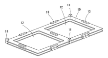
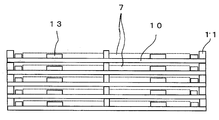
- the setter holding means is composed of a frame-shaped flat plate member 10 provided with a plurality of stacking protrusions 11 on the periphery.
- the rectangular flat plate member 10 includes square holes 12 on both the left and right sides, and the flat plate-like setter 7 is placed on this portion.
- a stacking protrusion 11 protrudes from the center of the side of the flat plate member 10 facing the left and right ends, and a positioning protrusion 13 lower than the stacking protrusion 11 protrudes from a position surrounding the hole 12. ing.
- FIG. 6 is a side view showing a state in which the setter holding means holds the flat setter 7 and is laminated in multiple stages, and the flat setter 7 is indicated by a dotted line.
- 70% or more of the outer peripheral side surface of the flat setter 7 is exposed in the firing furnace.
- the material is any one of Si—SiC, recrystallized SiC, and Si 3 N 4 —SiC having a high heat radiation rate, excellent heat uniformity can be ensured as in the first embodiment.
- the setter holding means can hold the flat setter 7 and stack them, there is an advantage that the handleability is excellent as compared with the first embodiment.
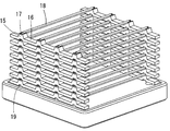
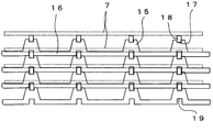
- the setter holding means is spanned between a pair of linear members 16 provided with a plurality of stacking projections 15 and facing each other, and the upper concave surface 17 of each stacking projection 15.
- the beam 18 is made up of.
- the stacking protrusion 15 is a mountain-shaped protrusion, and a recess 19 is formed below the protrusion.
- the beam 18 is a rod-shaped body having a square cross section, and both ends thereof are fitted into the upper concave surface 17 of the stacking projection 15, and the flat plate-like setter 7 is placed thereon.
- FIG. 8 is a side view showing a state in which the flat plate setter 7 is held on these beams 18 and laminated in multiple stages, and the flat plate setter 7 is indicated by a dotted line. As shown in FIG. 8, the lower concave portion 19 is fitted on the upper side of the beam 18 to stabilize the laminated state.
- the setter holding means can hold the flat plate-like setter 7 in the third embodiment, it can be stacked, so that there is an advantage that the handleability is excellent as compared with the first embodiment.
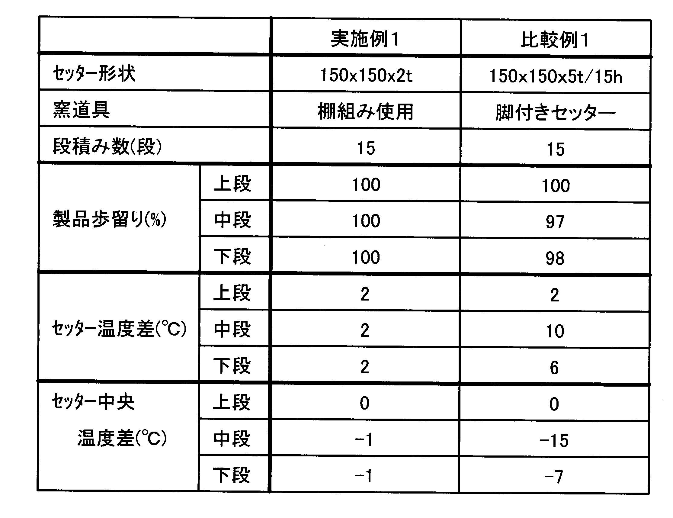
- a plate setter of 150 mm ⁇ 150 mm ⁇ 2 mm was inserted into the baking rack of the present invention to form a baking jig having a 15-layer structure (Example 1), and a setter of 150 mm ⁇ 150 mm ⁇ 5 mm
- a ceramic capacitor was fired (1300 ° C., 10 hours) under the same firing conditions using a structure (Comparative Example 1) in which 15 mm protrusions on the periphery were stacked in 15 steps.
- Table 1 shows the results of examining the product yield at each stage (“Product Yield (%)”), and the results of measuring the temperature difference between the end and the center of the setter constituting each stage (“Setter temperature difference (° C. ) "), The temperature of the center of the uppermost setter and the temperature difference of the center of the setter constituting each stage (“ setter central temperature difference (° C) ".
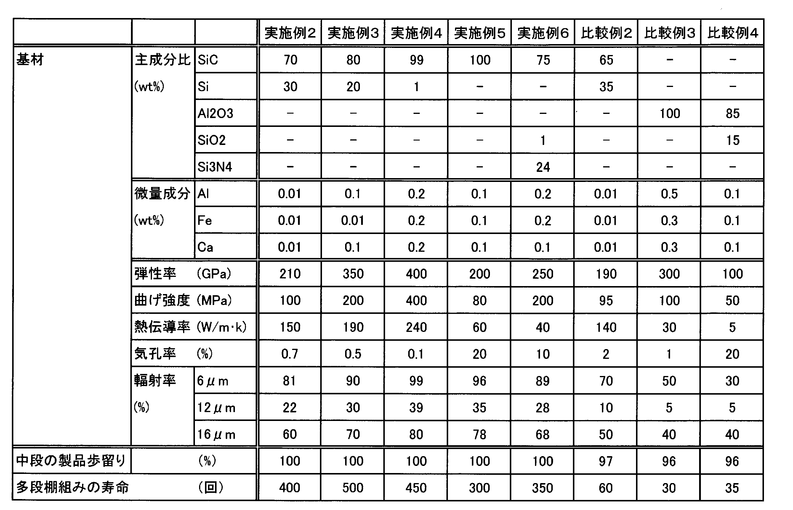
- the racks for firing according to claim 1 of the present invention were configured with the respective component ratios shown in Table 2 (Examples 2 to 6, Comparative Examples 2 to 4), and the dimensions were 150 mm ⁇ 150 mm ⁇ 2 mm.
- a flat setter was inserted to form a baking jig having a 15-layer structure.
- the ceramic capacitor was fired (1300 ° C., 10 hours) under the same firing conditions.
- Table 2 shows the results of measurement of the product yield of interruptions as a result of measuring the physical properties (elastic modulus, bending strength, thermal conductivity, porosity, emissivity) of the racks for firing according to Examples 2 to 6 and Comparative Examples 2 to 4.
- the lifetimes of the firing racks themselves (“lifetime of the multistage shelf assembly (times)”) are shown.
- Examples 2, 3 and 4 shown in Table 2 are Si—SiC containing 0.01 to 30% Si, Example 5 is recrystallized SiC, Example 6 is Si 3 N 4 —SiC, and Comparative Example 2 is Si—SiC having an excessive Si content, Comparative Example 3 is alumina, and Comparative Example 4 is alumina-silica.
- the firing rack according to claim 1 is made of any one of Si—SiC, recrystallized SiC, and Si 3 N 4 —SiC containing 0.01 to 30% Si.
- the baking rack according to claim 1 of the present invention was configured with the members having the chemical compositions of Comparative Examples 2 to 4, a remarkable decrease in the shelf life was observed in particular as the product yield deteriorated.
Landscapes
- Engineering & Computer Science (AREA)
- Chemical & Material Sciences (AREA)
- Ceramic Engineering (AREA)
- Mechanical Engineering (AREA)
- Manufacturing & Machinery (AREA)
- General Engineering & Computer Science (AREA)
- Chemical Kinetics & Catalysis (AREA)
- Materials Engineering (AREA)
- Structural Engineering (AREA)
- Organic Chemistry (AREA)
- Furnace Charging Or Discharging (AREA)
- Ceramic Products (AREA)
Abstract
Description
図1と図2は本発明の第1の実施形態を示すものである。本実施形態の焼成用ラック1は略立方体形状を有し、セッター保持手段は、4隅の垂直辺を構成する4本の角部垂直支柱2と、該4本の角部垂直支柱2(2a、2b、2c、2d)の下端部を支持する略ロ字状の下端支持枠4と、該4本の垂直支柱2の上端部を支持する略ロ字状の上端支持枠3から構成されている。図1に示すように、該焼成用ラック1は、平板状セッター7を挿入して使用するものである。
本発明の焼成用ラックは通常、不活性ガス雰囲気下で、1300~1450℃程度の高温条件下で使用される。このため本発明においては、セッター保持手段が0.01~30%のSiを含有するSi-SiC、再結晶SiC、Si3N4-SiCの何れかの材質から構成される。
図5と図6は、本発明の第2の実施形態を示すものである。本実施形態の焼成用ラック1は、セッター保持手段が、周辺部に複数の段積み用突起11を備えた枠状の平板部材10からなるものである。図5の実施形態では、長方形の平板部材10は左右両側に四角形の孔12を備え、この部分に平板状セッター7が載せられる。平板部材10の一辺の左右両端と対向する辺の中央部には段積み用突起11が突設され、孔12を囲む位置には段積み用突起11よりも低い位置決め用突起13が突設されている。
図7と図8は、本発明の第3の実施形態を示すものである。本実施形態の焼成用ラック1は、セッター保持手段が、複数の段積み用突起15を備え対向配置された一対の直線部材16と、各段積み用突起15の上部凹面17間に掛け渡された梁18とからなるものである。段積み用突起15は山型の突起であり、その下側には凹部19が形成されている。梁18は断面角型の棒状体であり、その両端が段積み用突起15の上部凹面17に嵌め込まれ、その上に平板状セッター7が載せられる。
2(2a、2b、2c、2d)角部垂直支柱
21 水平溝部
3 上端支持枠
4 下端支持枠
5(5aと5b)中間垂直支柱
51 水平孔部
6 梁
7 平板状セッター
8 突起部
10 平板部材
11 段積み用突起
12 四角形の孔
13 位置決め用突起
15 段積み用突起
16 直線部材
17 上部凹面
18 梁
19 凹部
Claims (11)
- 複数枚の平板状セッターをセッター保持手段により垂直方向に多段に保持する焼成用ラックであって、該セッター保持手段が、0.01~30%のSiを含有するSi-SiC、再結晶SiC、Si3N4-SiCの何れかの材質からなり、該セッター保持手段は、各平板状セッターをその外周側面の70~100%を露出させた状態で保持するものであることを特徴とする焼成用ラック。
- セッター保持手段が、セッター保持機構を備えた複数本の垂直支柱と、該垂直支柱の下端部を支持する下端支持枠と、該垂直支柱の上端部を支持する上端支持枠を有し、
該セッター保持機構が、垂直支柱の内側面に形成した複数の凹部または凸部、あるいは、平板状セッターを挟んで対面する垂直支柱間に渡した梁、の少なくとも何れかからなることを特徴とする請求項1に記載の焼成用ラック。 - 垂直支柱が、その4隅の垂直辺を構成する角部垂直支柱、および、該角部垂直支柱間に垂直配置された中間垂直支柱からなることを特徴とする請求項2に記載の焼成用ラック。
- セッター保持手段が、周辺部に複数の段積み用突起を備えた枠状の平板部材からなり、平板状セッターを保持させた状態で多段に積層されたことを特徴とする請求項1に記載の焼成用ラック。
- セッター保持手段が、複数の段積み用突起を備え対向配置された一対の直線部材と、各段積み用突起の上部凹面間に掛け渡された梁とからなり、これらの梁の上に平板状セッターを保持させた状態で多段に積層されたことを特徴とする請求項1に記載の焼成用ラック。
- セッター保持手段を構成する部材が、Si-SiCからなり、その化学組成はSiC:70~99%、Si:1~30%であり、SiC+Siを100%として、さらにAl:0.01~0.2%、Fe:0.01~0.2%、Ca:0.01~0.2%を含有することを特徴とする請求項1~4の何れかに記載の焼成用ラック。
- セッター保持手段を構成する部材の熱輻射率が、波長8μmで80~100%、波長12μmで20~40%、波長19μmで60~80%であることを特徴とする請求項6に記載の焼成用ラック。
- セッター保持手段を構成する部材の算術平均による表面粗さがRa=0.1~30μm、弾性率が200~400GPa、強度が100~400MPaで、室温における熱伝導率が150~240W/m・k、気孔率が1%以下であることを特徴とする請求項6又は7に記載の焼成用ラック。
- セッター保持手段を構成する部材が再結晶SiCからなり、その化学組成はSiC:99~100%であり、SiCを100%としてさらにAl:0.01~0.2%、Fe:0.01~0.2%、Ca:0.01~0.2%を含有することを特徴とする請求項1~4の何れかに記載の焼成用ラック。
- セッター保持手段を構成する部材がSi3N4-SiCからなり、その化学組成はSiC:70~80%、Si3N4:20~30%であり、SiC+Si3N4を100%としてさらにAl:0.1~0.5%、Fe:0.1~0.5%、Ca:0.01~0.2%を含有することを特徴とする請求項1~4の何れかに記載の焼成用ラック。
- 平板状セッターの材質が、0.01~30%のSiを含有するSi-SiCであることを特徴とする請求項1~4の何れかに記載の焼成用ラック。
Priority Applications (5)
| Application Number | Priority Date | Filing Date | Title |
|---|---|---|---|
| PH1/2013/500131A PH12013500131A1 (en) | 2010-07-26 | 2011-07-25 | Rack for firing |
| KR1020137001813A KR101726912B1 (ko) | 2010-07-26 | 2011-07-25 | 소성용 랙 |
| MYPI2013000122A MY184778A (en) | 2010-07-26 | 2011-07-25 | Rack for firing |
| CN201180034397.0A CN103097845B (zh) | 2010-07-26 | 2011-07-25 | 烧成用机架 |
| JP2012526489A JP5722897B2 (ja) | 2010-07-26 | 2011-07-25 | 焼成用ラック |
Applications Claiming Priority (2)
| Application Number | Priority Date | Filing Date | Title |
|---|---|---|---|
| JP2010167311 | 2010-07-26 | ||
| JP2010-167311 | 2010-07-26 |
Publications (1)
| Publication Number | Publication Date |
|---|---|
| WO2012014835A1 true WO2012014835A1 (ja) | 2012-02-02 |
Family
ID=45530043
Family Applications (1)
| Application Number | Title | Priority Date | Filing Date |
|---|---|---|---|
| PCT/JP2011/066826 Ceased WO2012014835A1 (ja) | 2010-07-26 | 2011-07-25 | 焼成用ラック |
Country Status (7)
| Country | Link |
|---|---|
| JP (1) | JP5722897B2 (ja) |
| KR (1) | KR101726912B1 (ja) |
| CN (1) | CN103097845B (ja) |
| MY (1) | MY184778A (ja) |
| PH (1) | PH12013500131A1 (ja) |
| TW (1) | TWI528013B (ja) |
| WO (1) | WO2012014835A1 (ja) |
Cited By (11)
| Publication number | Priority date | Publication date | Assignee | Title |
|---|---|---|---|---|
| CN103743204A (zh) * | 2014-01-08 | 2014-04-23 | 长兴明晟冶金炉料有限公司 | 球形炉料烘箱 |
| JP2015048950A (ja) * | 2013-08-30 | 2015-03-16 | 日本碍子株式会社 | ラック |
| JP2016537600A (ja) * | 2013-10-07 | 2016-12-01 | サン−ゴバン セラミックス アンド プラスティクス,インコーポレイティド | 耐火物 |
| TWI684739B (zh) * | 2019-04-19 | 2020-02-11 | 群翊工業股份有限公司 | 基板烘烤設備及基板烘烤方法 |
| EP3680971A4 (en) * | 2018-04-18 | 2021-01-13 | Lg Chem, Ltd. | CARTRIDGE TO SHOOT |
| JPWO2021033375A1 (ja) * | 2019-08-16 | 2021-09-13 | 日本碍子株式会社 | 焼成用ラック及び焼成用治具 |
| US20220299268A1 (en) * | 2021-03-16 | 2022-09-22 | Ssi Sintered Specialties, Llc | Racking system for use in continuous sintering furnaces |
| JP7515761B1 (ja) | 2024-03-28 | 2024-07-12 | 株式会社ノリタケカンパニーリミテド | 焼成用治具 |
| JP7515762B1 (ja) | 2024-03-28 | 2024-07-12 | 株式会社ノリタケカンパニーリミテド | 焼成用治具 |
| JP7560691B1 (ja) | 2024-03-28 | 2024-10-02 | ノリタケ株式会社 | 焼成用治具 |
| JP7560690B1 (ja) | 2024-03-28 | 2024-10-02 | ノリタケ株式会社 | 焼成用治具およびフレーム |
Families Citing this family (6)
| Publication number | Priority date | Publication date | Assignee | Title |
|---|---|---|---|---|
| CN107024113A (zh) * | 2016-01-31 | 2017-08-08 | 湖南大学 | 一种砂轮立式烧结装置 |
| TWI612024B (zh) * | 2016-06-29 | 2018-01-21 | 丸十股份有限公司 | 陶瓷成形體的燒製輔助具 |
| JP6811196B2 (ja) * | 2018-01-10 | 2021-01-13 | 日本碍子株式会社 | 焼成用セッター |
| KR102610471B1 (ko) | 2018-08-22 | 2023-12-05 | 주식회사 엘지화학 | 고체 산화물 연료전지 셀 소성용 장치 및 소성 방법 |
| CN112496319A (zh) * | 2019-09-16 | 2021-03-16 | 宿迁启祥电子科技有限公司 | 一种烧结装置及钨合金材料的制备方法 |
| CN113634821B (zh) * | 2021-08-04 | 2022-06-03 | 江苏陆氏金刚石工具有限公司 | 一种避免金刚石锯片相互黏结的承载装置 |
Citations (8)
| Publication number | Priority date | Publication date | Assignee | Title |
|---|---|---|---|---|
| JPH061660A (ja) * | 1992-06-25 | 1994-01-11 | Ngk Insulators Ltd | 耐クリープ性Si−SiC質焼結体 |
| JPH07280207A (ja) * | 1994-04-14 | 1995-10-27 | Ngk Insulators Ltd | ラジアントチューブ |
| JPH10311686A (ja) * | 1997-05-13 | 1998-11-24 | Ngk Insulators Ltd | 窯炉用棚組構造体 |
| JP2000319721A (ja) * | 1999-05-07 | 2000-11-21 | Ngk Insulators Ltd | セラミックチューブ及びこれを用いた誘導加熱炉 |
| JP2001328870A (ja) * | 2000-05-19 | 2001-11-27 | Taiyo Yuden Co Ltd | セラミックの焼成方法、トンネル式焼成炉、セラミック電子部品の製造方法及び装置、セラミック電子部品の焼成用収納体 |
| JP2003014378A (ja) * | 2001-06-27 | 2003-01-15 | Maruju:Kk | 焼成用治具 |
| JP2005082450A (ja) * | 2003-09-09 | 2005-03-31 | Ngk Insulators Ltd | 窒化珪素結合SiC耐火物及びその製造方法 |
| JP2005298311A (ja) * | 2004-04-16 | 2005-10-27 | Ngk Insulators Ltd | セラミックス複合材 |
Family Cites Families (8)
| Publication number | Priority date | Publication date | Assignee | Title |
|---|---|---|---|---|
| DE4392693T1 (de) * | 1992-06-08 | 1994-09-08 | Ngk Insulators Ltd | Temperaturwechselbeständige, kriechfeste und oxydationsfeste Einsätze |
| JP2000074571A (ja) | 1998-09-03 | 2000-03-14 | Toshiba Ceramics Co Ltd | 焼成用治具 |
| JP2000111269A (ja) * | 1998-09-30 | 2000-04-18 | Toshiba Ceramics Co Ltd | 焼成用治具 |
| JP4049545B2 (ja) * | 2001-03-22 | 2008-02-20 | 日本碍子株式会社 | SiC質熱処理用治具 |
| JP4869048B2 (ja) * | 2006-02-15 | 2012-02-01 | 日本碍子株式会社 | 平板瓦焼成用窯道具 |
| JP4818300B2 (ja) | 2008-03-25 | 2011-11-16 | 日本碍子株式会社 | 電子部品焼成用セッター及びその製造方法 |
| JP4787308B2 (ja) * | 2008-12-01 | 2011-10-05 | 日本碍子株式会社 | 焼成用棚組 |
| CN201476585U (zh) * | 2009-08-06 | 2010-05-19 | 江西雅华工业陶瓷有限公司 | 整体框架式陶瓷产品承烧板 |
-
2011
- 2011-07-25 WO PCT/JP2011/066826 patent/WO2012014835A1/ja not_active Ceased
- 2011-07-25 KR KR1020137001813A patent/KR101726912B1/ko active Active
- 2011-07-25 CN CN201180034397.0A patent/CN103097845B/zh active Active
- 2011-07-25 PH PH1/2013/500131A patent/PH12013500131A1/en unknown
- 2011-07-25 JP JP2012526489A patent/JP5722897B2/ja active Active
- 2011-07-25 MY MYPI2013000122A patent/MY184778A/en unknown
- 2011-07-25 TW TW100126136A patent/TWI528013B/zh active
Patent Citations (8)
| Publication number | Priority date | Publication date | Assignee | Title |
|---|---|---|---|---|
| JPH061660A (ja) * | 1992-06-25 | 1994-01-11 | Ngk Insulators Ltd | 耐クリープ性Si−SiC質焼結体 |
| JPH07280207A (ja) * | 1994-04-14 | 1995-10-27 | Ngk Insulators Ltd | ラジアントチューブ |
| JPH10311686A (ja) * | 1997-05-13 | 1998-11-24 | Ngk Insulators Ltd | 窯炉用棚組構造体 |
| JP2000319721A (ja) * | 1999-05-07 | 2000-11-21 | Ngk Insulators Ltd | セラミックチューブ及びこれを用いた誘導加熱炉 |
| JP2001328870A (ja) * | 2000-05-19 | 2001-11-27 | Taiyo Yuden Co Ltd | セラミックの焼成方法、トンネル式焼成炉、セラミック電子部品の製造方法及び装置、セラミック電子部品の焼成用収納体 |
| JP2003014378A (ja) * | 2001-06-27 | 2003-01-15 | Maruju:Kk | 焼成用治具 |
| JP2005082450A (ja) * | 2003-09-09 | 2005-03-31 | Ngk Insulators Ltd | 窒化珪素結合SiC耐火物及びその製造方法 |
| JP2005298311A (ja) * | 2004-04-16 | 2005-10-27 | Ngk Insulators Ltd | セラミックス複合材 |
Cited By (27)
| Publication number | Priority date | Publication date | Assignee | Title |
|---|---|---|---|---|
| JP2015048950A (ja) * | 2013-08-30 | 2015-03-16 | 日本碍子株式会社 | ラック |
| US12298078B2 (en) | 2013-10-07 | 2025-05-13 | Saint-Gobain Ceramics & Plastics, Inc. | Refractory article |
| JP2016537600A (ja) * | 2013-10-07 | 2016-12-01 | サン−ゴバン セラミックス アンド プラスティクス,インコーポレイティド | 耐火物 |
| US10030910B2 (en) | 2013-10-07 | 2018-07-24 | Saint-Gobain Ceramics & Plastics, Inc. | Refractory article |
| JP2019052842A (ja) * | 2013-10-07 | 2019-04-04 | サン−ゴバン セラミックス アンド プラスティクス,インコーポレイティド | 耐火物 |
| EP3055271B1 (en) | 2013-10-07 | 2019-05-01 | Saint-Gobain Ceramics&Plastics, Inc. | Refractory support structure article |
| EP3055271B2 (en) † | 2013-10-07 | 2024-05-22 | Saint-Gobain Ceramics & Plastics, Inc. | Refractory support structure article |
| US11340018B2 (en) | 2013-10-07 | 2022-05-24 | Saint-Gobain Ceramics & Plastics, Inc. | Refractory article |
| CN103743204A (zh) * | 2014-01-08 | 2014-04-23 | 长兴明晟冶金炉料有限公司 | 球形炉料烘箱 |
| EP3680971A4 (en) * | 2018-04-18 | 2021-01-13 | Lg Chem, Ltd. | CARTRIDGE TO SHOOT |
| JP2021509758A (ja) * | 2018-04-18 | 2021-04-01 | エルジー・ケム・リミテッド | 焼成用カートリッジ |
| JP7019915B2 (ja) | 2018-04-18 | 2022-02-16 | エルジー・ケム・リミテッド | 焼成用カートリッジ |
| US11276864B2 (en) | 2018-04-18 | 2022-03-15 | Lg Chem, Ltd. | Cartridge for firing |
| TWI684739B (zh) * | 2019-04-19 | 2020-02-11 | 群翊工業股份有限公司 | 基板烘烤設備及基板烘烤方法 |
| CN114207372A (zh) * | 2019-08-16 | 2022-03-18 | 日本碍子株式会社 | 烧成用架及烧成用夹具 |
| JP7285271B2 (ja) | 2019-08-16 | 2023-06-01 | 日本碍子株式会社 | 焼成用ラック及び焼成用治具 |
| JPWO2021033375A1 (ja) * | 2019-08-16 | 2021-09-13 | 日本碍子株式会社 | 焼成用ラック及び焼成用治具 |
| US20220299268A1 (en) * | 2021-03-16 | 2022-09-22 | Ssi Sintered Specialties, Llc | Racking system for use in continuous sintering furnaces |
| US12372304B2 (en) * | 2021-03-16 | 2025-07-29 | Dsb Technologies, Llc | Racking system for use in continuous sintering furnaces |
| JP7515761B1 (ja) | 2024-03-28 | 2024-07-12 | 株式会社ノリタケカンパニーリミテド | 焼成用治具 |
| JP7515762B1 (ja) | 2024-03-28 | 2024-07-12 | 株式会社ノリタケカンパニーリミテド | 焼成用治具 |
| JP7560691B1 (ja) | 2024-03-28 | 2024-10-02 | ノリタケ株式会社 | 焼成用治具 |
| JP7560690B1 (ja) | 2024-03-28 | 2024-10-02 | ノリタケ株式会社 | 焼成用治具およびフレーム |
| JP2025151522A (ja) * | 2024-03-28 | 2025-10-09 | ノリタケ株式会社 | 焼成用治具およびフレーム |
| JP2025151525A (ja) * | 2024-03-28 | 2025-10-09 | ノリタケ株式会社 | 焼成用治具 |
| JP2025151524A (ja) * | 2024-03-28 | 2025-10-09 | ノリタケ株式会社 | 焼成用治具 |
| JP2025151523A (ja) * | 2024-03-28 | 2025-10-09 | ノリタケ株式会社 | 焼成用治具 |
Also Published As
| Publication number | Publication date |
|---|---|
| KR101726912B1 (ko) | 2017-04-13 |
| TWI528013B (zh) | 2016-04-01 |
| JP5722897B2 (ja) | 2015-05-27 |
| PH12013500131A1 (en) | 2016-07-29 |
| CN103097845B (zh) | 2015-05-06 |
| KR20130130676A (ko) | 2013-12-02 |
| TW201224382A (en) | 2012-06-16 |
| JPWO2012014835A1 (ja) | 2013-09-12 |
| MY184778A (en) | 2021-04-21 |
| CN103097845A (zh) | 2013-05-08 |
Similar Documents
| Publication | Publication Date | Title |
|---|---|---|
| JP5722897B2 (ja) | 焼成用ラック | |
| EP2251628B1 (en) | Kiln tool plate for firing ceramic | |
| JP2021134092A (ja) | 軽量窯道具及びその製造方法 | |
| JP7468769B2 (ja) | 窒化珪素焼結基板の製造方法 | |
| JP5910366B2 (ja) | 結晶化ガラス板の製造方法 | |
| CN104884407A (zh) | 热屏蔽系统 | |
| JP2023015295A (ja) | 加熱炉 | |
| CN114207372A (zh) | 烧成用架及烧成用夹具 | |
| JP6891991B2 (ja) | 窒化珪素焼結基板の製造方法 | |
| JP6766509B2 (ja) | 窒化珪素焼結基板の製造方法 | |
| KR102341028B1 (ko) | 랙 | |
| JP6402131B2 (ja) | 焼成治具の製造方法 | |
| CN114945787A (zh) | 烧成用承烧板 | |
| JPH1054672A (ja) | セラミックス焼成用セッター | |
| JP2005082450A (ja) | 窒化珪素結合SiC耐火物及びその製造方法 | |
| JP2009143730A (ja) | 板状セラミックス成形体の焼成方法および板状セラミックス成形体 | |
| JP7663332B2 (ja) | 基板保持部材、およびその製造方法 | |
| JPH10111084A (ja) | 焼成用棚板およびそれを用いた焼成方法 | |
| JP4581575B2 (ja) | 板状セラミック体の製造方法及びセラミック焼成用荷重付加部材 | |
| JP2005249235A (ja) | 熱処理用さや及びその製造方法 | |
| JP5212291B2 (ja) | 成形体の焼成方法及びその成形体の焼成用保持具 | |
| KR20250145508A (ko) | 소성용 지그 및 프레임 | |
| JP2005075710A (ja) | フェライト焼成用治具 | |
| JP4287786B2 (ja) | セラミック焼成用さや、及び、セラミック成形体の焼成方法 | |
| JP2001174164A (ja) | プッシャー式トンネル炉用台板 |
Legal Events
| Date | Code | Title | Description |
|---|---|---|---|
| WWE | Wipo information: entry into national phase |
Ref document number: 201180034397.0 Country of ref document: CN |
|
| 121 | Ep: the epo has been informed by wipo that ep was designated in this application |
Ref document number: 11812425 Country of ref document: EP Kind code of ref document: A1 |
|
| WWE | Wipo information: entry into national phase |
Ref document number: 2012526489 Country of ref document: JP |
|
| WWE | Wipo information: entry into national phase |
Ref document number: 12013500131 Country of ref document: PH |
|
| ENP | Entry into the national phase |
Ref document number: 20137001813 Country of ref document: KR Kind code of ref document: A |
|
| NENP | Non-entry into the national phase |
Ref country code: DE |
|
| 122 | Ep: pct application non-entry in european phase |
Ref document number: 11812425 Country of ref document: EP Kind code of ref document: A1 |