WO2012008580A1 - マグネトロン用エンドハットおよびその製造方法並びにマグネトロン - Google Patents
マグネトロン用エンドハットおよびその製造方法並びにマグネトロン Download PDFInfo
- Publication number
- WO2012008580A1 WO2012008580A1 PCT/JP2011/066243 JP2011066243W WO2012008580A1 WO 2012008580 A1 WO2012008580 A1 WO 2012008580A1 JP 2011066243 W JP2011066243 W JP 2011066243W WO 2012008580 A1 WO2012008580 A1 WO 2012008580A1
- Authority
- WO
- WIPO (PCT)
- Prior art keywords
- less
- mass
- content
- magnetron
- end hat
- Prior art date
- Legal status (The legal status is an assumption and is not a legal conclusion. Google has not performed a legal analysis and makes no representation as to the accuracy of the status listed.)
- Ceased
Links
Images


Classifications
-
- H—ELECTRICITY
- H01—ELECTRIC ELEMENTS
- H01J—ELECTRIC DISCHARGE TUBES OR DISCHARGE LAMPS
- H01J23/00—Details of transit-time tubes of the types covered by group H01J25/00
- H01J23/02—Electrodes; Magnetic control means; Screens
- H01J23/04—Cathodes
- H01J23/05—Cathodes having a cylindrical emissive surface, e.g. cathodes for magnetrons
-
- H—ELECTRICITY
- H01—ELECTRIC ELEMENTS
- H01J—ELECTRIC DISCHARGE TUBES OR DISCHARGE LAMPS
- H01J23/00—Details of transit-time tubes of the types covered by group H01J25/00
- H01J23/02—Electrodes; Magnetic control means; Screens
- H01J23/04—Cathodes
-
- H—ELECTRICITY
- H01—ELECTRIC ELEMENTS
- H01J—ELECTRIC DISCHARGE TUBES OR DISCHARGE LAMPS
- H01J25/00—Transit-time tubes, e.g. klystrons, travelling-wave tubes, magnetrons
- H01J25/50—Magnetrons, i.e. tubes with a magnet system producing an H-field crossing the E-field
- H01J25/52—Magnetrons, i.e. tubes with a magnet system producing an H-field crossing the E-field with an electron space having a shape that does not prevent any electron from moving completely around the cathode or guide electrode
- H01J25/58—Magnetrons, i.e. tubes with a magnet system producing an H-field crossing the E-field with an electron space having a shape that does not prevent any electron from moving completely around the cathode or guide electrode having a number of resonators; having a composite resonator, e.g. a helix
- H01J25/587—Multi-cavity magnetrons
Definitions
- the present invention relates to a magnetron end hat, a method for manufacturing the same, and a magnetron using the same, and more particularly to an end hat for a magnetron capable of extending the life and exhibiting high reliability over a long period of time. And a manufacturing method thereof and a magnetron using the same.
- a cathode part of a magnetron used in a microwave oven or the like includes a coiled filament 1 that emits thermoelectrons, and an upper end and a lower end of the coiled filament 1 via a Mo-Ru brazing material 2 respectively.
- the upper end hat 3 and the lower end hat 4 made of Mo joined together, the center lead 5 connected and fixed to the upper end hat 3, and the side lead 6 connected to the lower end hat 4.
- Magnetron is a kind of bipolar tube that is widely used in microwave communication devices and home appliances as an electron tube for generating microwaves. This magnetron generates a microwave by applying a high DC voltage of several kilovolts between a cylindrical cathode (cathode) and an anode (anode) surrounding the cathode. At present, it is widely used as a microwave oven part for cooking food by an induction heating method using a microwave having a frequency of 2450 MHz and an output of about 500 to 1500 W.
- Patent Document 1 discloses a method in which Mo powder is molded to produce an intermediate sintered body, an intermediate sintered body of Mo—Ru brazing material is placed, and then main sintering is performed. This method improves the bonding strength between the Mo—Ru brazing material and the Mo sintered body (end hat).
- the cause is carbon present on the surface of the Mo sintered body (end hat). Carbon is the resin binder remaining when the Mo molded body is made. When carbon is present on the end hat surface, the end hat surface is easily sputtered when a high voltage is applied in a vacuum tube. Due to this sputtering phenomenon, the surface of the end hat is scraped and eroded and carbon is increased in the vacuum. As a result, it has been found that the output of the magnetron decreases and the life as a magnetron decreases.
- the present invention has been made in view of such technical problems, and an object of the present invention is to provide an end hat with high end hat reliability, excellent manufacturing yield and manufacturing efficiency, a manufacturing method thereof, and a magnetron. To do.
- the magnetron end hat according to the present invention is a magnetron end hat made of a Mo sintered body, and the carbon content in the surface region from the surface of the Mo sintered body to 100 ⁇ m is 30 ppm or less. And the carbon content in the central region within ⁇ 100 ⁇ m from the central point in the thickness direction of the Mo sintered body is 50 to 300 ppm.
- the density of the Mo sintered body is preferably 9.6 to 10.0 g / cm 3 .
- the Mo sintered body has a Mo content of 99.9% by mass or more and, as an impurity element, an Al content of 0.005% by mass or less, and a Ca content.
- the content is 0.002% by mass or less, the Mn content is 0.002% by mass or less, the Ni content is 0.008% by mass or less, and the Pb content is 0.002% by mass or less.
- the Si content is preferably 0.005% by mass or less, and the Sn content is preferably 0.002% by mass or less.
- the magnetron end hat is preferably provided with a Mo-Ru brazing material.
- the Mo—Ru brazing filler metal has a carbon content of 0.05% by mass or less, an Fe content of 0.009% by mass or less, and an Ni content as an impurity element.
- the amount is preferably 0.007% by mass or less.
- the magnetron according to the present invention is characterized by being formed using the above-described magnetron end hat.
- the method for producing an end hat for a magnetron according to the present invention includes a pressing step of press-molding an end-hat-shaped Mo molded body using Mo powder having a purity of 99.9% by mass or more and a resin binder, and the Mo molded body. Firing in an oxidation-reduction atmosphere to obtain a first fired body, and a second firing step to fire this first fired body in a reducing atmosphere to obtain a second fired body. It is characterized by comprising.
- the oxidation-reduction atmosphere is preferably wet hydrogen gas.
- the wet hydrogen gas flow rate is 0.2 m 3 / hour or more, the maximum temperature reached is 1000 to 1200 ° C., and the holding time at the maximum temperature is 1 to 4 hours. It is preferably carried out under conditions.
- the first firing step is preferably performed by raising the temperature from 600 ° C. to the highest temperature over 3 to 7 hours.
- the hydrogen gas flow rate is 0.2 m 3 / hour or more
- the maximum reached temperature is 1600 to 1900 ° C.
- the holding time at the maximum reached temperature is 30 minutes to 5 hours. It is preferably carried out below.
- the obtained magnetron end hat has a carbon content in a surface region from the surface of the Mo sintered body to 100 ⁇ m of 30 ppm or less, while the thickness of the Mo sintered body is The carbon content in the central region within ⁇ 100 ⁇ m from the center point in the direction is preferably 50 to 300 ppm.
- the magnetron end hat of the present invention since there is little residual carbon in the surface area of the Mo end hat, it is less likely to be sputtered when used as a magnetron. Can be obtained.
- the end hat of the present invention can be efficiently manufactured with a high yield.
- the magnetron end hat according to the present invention is a magnetron end hat made of a Mo sintered body, wherein the carbon content in the surface region from the surface of the Mo sintered body to 100 ⁇ m is 30 ppm or less, and the thickness of the Mo sintered body is The carbon content in the central region within ⁇ 100 ⁇ m from the central point in the vertical direction is 50 to 300 ppm.
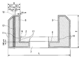
- FIG. 2 shows an example of a magnetron end hat.
- 2 is a brazing material
- 3 is an upper end hat (end hat main body)
- 7 is a center lead mounting hole
- 8 is a joint bottom surface between the end hat and the brazing material
- 9 is an end hat and brazing material. It is a joining side surface part.
- the upper end hat is illustrated in FIG. 2, the basic structure is the same in the lower end hat.
- FIG. 2 illustrates a state where the brazing material 2 is mounted.
- the main body 3 of the end hat is made of a Mo sintered body.
- the Mo sintered body is obtained by forming Mo powder and sintering the formed body under predetermined conditions to obtain a Mo sintered body. A preferred production method will be described later.
- the magnetron end hat according to the present invention is made of a Mo sintered body, and as shown in FIG. 2, the carbon content in the surface region 11 from the surface S to 100 ⁇ m is 30 ppm or less, and the Mo sintered body has a thickness direction.
- the carbon content in the central region 12 within ⁇ 100 ⁇ m from the central point 10 is 100 to 300 ppm.
- the “surface” indicates an arbitrary surface S of the end hat main body.
- the “surface region of 100 ⁇ m from the surface” indicates the region 11 from the arbitrary surface S up to 100 ⁇ m in the depth direction.
- the carbon content in the surface region 11 is 30 ppm or less. Preferably, it is 20 ppm or less (including 0 ppm).
- the carbon content in the central region 12 within ⁇ 100 ⁇ m from the central point 10 in the thickness direction of the Mo sintered body (end hat main body) is 50 to 300 ppm.
- the “center region” indicates a region of ⁇ 100 ⁇ m from the center point (W / 2) of W with respect to the thickness W of the Mo sintered body in FIG.
- FIG. 2 illustrates the center region of the side wall of the end hat, a sample (sample) in the center region may be collected from the bottom.
- the carbon content is measured by the high frequency combustion-infrared absorption method.
- the surface S is scraped off to 100 ⁇ m to obtain a sample.
- the sample for measuring the carbon content in the central region is measured using a sample obtained by scraping the region of (W / 2) ⁇ 100 ⁇ m.
- the carbon content in the surface region 11 and the central region 12 is relatively very small. If carbon is present in the surface region of the Mo sintered body (end hat main body), the surface of the Mo sintered body is easily sputtered and eroded. Therefore, it is preferable that no carbon exists in the surface region 11.
- Mo powder and a resin binder are mixed to produce a molded body and sintered. When sintered at this time, the resin binder is burned out, but carbon remains as an impurity. For this reason, molding without using a resin binder is also conceivable, but there is a problem that the production yield of the molded body is greatly reduced. However, since the use of a resin binder is inevitable in reality, impurity carbon tends to remain in the Mo sintered body.
- Magnetron usage environment is generally microwaves with a frequency of about 2450 MHz and an output of about 500-1500 W.
- electrons are emitted from the coiled filament 1 toward the anode between the coiled filament 1 and the anode (not shown) in a vacuum vessel (not shown). This emitted electron is used to convert it into a large microwave. For this reason, it is important to efficiently convert the electrons emitted in the vacuum vessel into microwaves.
- the impurities in the Mo sintered body carbon is an element that is particularly easily sputtered, and easily becomes an impurity in the vacuum tube. Further, since carbon is sputtered, Mo is easily sputtered together, so that the durability of the end hat is lowered. Therefore, in the present invention, the amount of carbon in the surface region is reduced to a predetermined range.
- the density of the Mo sintered body is preferably 9.6 g / cm 3 or more. More preferably, it is 9.6 to 10.0 g / cm 3 .
- the density of the Mo sintered body is less than 9.6 g / cm 3 , the strength of the end hat may be insufficient.
- the theoretical density of Mo is 10.22 g / cm 3 (see Physics and Chemistry Dictionary). When the density is close to the theoretical density, the strength of the Mo sintered body is improved. However, when the density is excessively high, Ru in the brazing material becomes difficult to diffuse.
- the density of the Mo sintered body is preferably 9.6 g / cm 3 or more, more preferably 9.6 to 10.0 g / cm 3 , and still more preferably 9.6 to 9.8 g / cm 3. 3 range.
- the density is measured by Archimedes method.
- the Mo sintered body has a Mo (molybdenum) ratio of 99.9% by mass or more. That is, the impurity element is preferably 0.1% by mass or less. More preferably, as the impurity element, the Al content is 0.005 mass% or less, the Ca content is 0.003 mass% or less, the Cr content is 0.005 mass% or less, and the Cu content Is 0.002 mass% or less, Fe content is 0.03 mass% or less, Mg content is 0.002 mass% or less, Mn content is 0.002 mass% or less, Ni The content is 0.008% by mass or less, the Pb content is 0.002% by mass or less, the Si content is 0.005% by mass or less, and the Sn content is 0.002% by mass or less. It is preferable. When there are many impurity elements as described above, the strength of the end hat, the life of the magnetron, the bonding failure with the Mo—Ru brazing material, and the like may be caused.
- the end hat preferably has a diameter L of 10 mm or less and a thickness T of 4 mm or less.
- the Mo—Ru brazing material is preferably a brazing material having a Ru content of 35 to 50 mass%. If the Ru content is less than 35% by mass or excessively more than 50% by mass, the melting point of the brazing filler metal will increase. Since Mo and Ru form a eutectic, the Ru melting point is the lowest at 1960 ° C., and the Ru content is in the vicinity of the composition of Ru 42.9 mass% —Mo balance.
- the Mo—Ru brazing material has a carbon content as an impurity element of 0.05 mass% or less, an Fe content of 0.009 mass% or less, and a Ni content of 0.007 mass% or less. It is preferable that If a large amount of impurities is contained in the brazing material, it may be scattered in the vacuum vessel.
- the magnetron end hat according to the present invention may have a structure in which an end hat made of a Mo sintered body and a Mo—Ru brazing material are integrally joined.
- the end hat is configured using an upper end hat and a lower end hat, and constitutes a cathode portion of the magnetron. Either the upper end hat or the lower end hat must face the brazing material attachment portion downward. At this time, if the joining of the brazing material and the end hat is weak, the brazing material is peeled off. When the brazing material is peeled off, it becomes defective and the production yield is lowered. Therefore, it is important to make the joint between the end hat and the brazing material strong.
- Ru of the Mo—Ru brazing material is diffused in the Mo sintered body. It is preferable that the region in which Ru is diffused is a region extending 5 ⁇ m or more from the bonding interface.
- a joining interface is the surface of Mo sintered compact (end hat).
- the joining bottom surface portion 8 between the end hat and the brazing material is first mentioned.
- Ru in the brazing material diffuses in the direction of the end hat, whereby the joining strength of the brazing material can be improved.
- the joint side surface portion 9 between the end hat and the brazing material similarly, if Ru is diffused in the brazing material, the joining strength of the brazing material is improved.
- the production method of the magnetron end hat of the present invention is not particularly limited, but the following method can be mentioned as a method of producing efficiently with a high yield.
- the method for producing an end hat for a magnetron according to the present invention includes a pressing step of press-molding an end-hat-shaped Mo molded body using Mo powder having a purity of 99.9% by mass or more and a resin binder, and oxidizing the Mo molded body.
- a first firing step in which a first fired body is obtained by firing in a reducing atmosphere; and a second firing step in which the first fired body is fired in a reducing atmosphere to obtain a second fired body. It is characterized by.
- Mo powder having a purity of 99.9% by mass or more is prepared.
- the Mo powder preferably has an average particle size of 1 to 8 ⁇ m.
- the amount of impurity elements in the Mo powder is 0.1% by mass or less. More preferably, the Al content as an impurity element is 0.005 mass% or less, the Ca content is 0.003 mass% or less, the Cr content is 0.005 mass% or less, and the Cu content Is 0.002 mass% or less, Fe content is 0.03 mass% or less, Mg content is 0.002 mass% or less, Mn content is 0.002 mass% or less, Ni The content is 0.008% by mass or less, the Pb content is 0.002% by mass or less, the Si content is 0.005% by mass or less, and the Sn content is 0.002% by mass or less.
- the carbon content is 0.01% by mass or less. It is preferable to use Mo powder with a low content of such impurity elements.
- the Mo powder and the resin binder are mixed and granulated.
- a normal resin binder such as PVA (polyvinyl alcohol) can be applied.
- the obtained Mo granulated powder is packed in a mold and press-molded to perform a press step of obtaining an end-hat-shaped Mo molded body.
- the pressing pressure is preferably in the range of 3 to 13 ton / cm 2 (294 to 1274 MPa).
- the press pressure is less than 3 ton / cm 3 , the strength of the molded body is insufficient.
- 13 ton / cm 2 the density of the molded body becomes excessively high and Ru diffusion hardly occurs.
- a preferred pressing pressure is in the range of 4 to 10 ton / cm 2 .
- a first firing step is performed in which the obtained Mo molded body is fired in an oxidation-reduction atmosphere to obtain a first fired body.
- the maximum temperature is 1000 to 1200 ° C. and the holding time at the maximum temperature is 1 to 4 hours.
- the first firing step is positioned as pre-sintering (or intermediate sintering before the main sintering) when the second firing step described later is the main sintering.
- the redox atmosphere is preferably wet hydrogen gas.
- Wet hydrogen gas is hydrogen gas containing water vapor.
- the final product is not intended to densify the Mo sintered body (end hat), but by firing in an oxidation-reduction atmosphere, the surface of the Mo sintered body is removed and the Mo firing is performed. This is a process aimed at preventing the union from being oxidized more than necessary.
- wet hydrogen hydrogen gas containing water vapor
- carbon can be removed from the surface of the Mo sintered body. The removed carbon is removed as carbon dioxide (CO 2 ) or carbon monoxide (CO). This is because water vapor (H 2 O) heated by heating easily reacts with carbon (C) and is easily removed from the Mo sintered body as carbon monoxide (CO) or carbon dioxide (CO 2 ).
- the temperature of the molded body it is preferable to raise the temperature of the molded body from a temperature of 600 ° C. to a maximum temperature over 3 to 7 hours.
- the rate of temperature rise is too fast, non-uniform portions appear in the disappearance and densification of the binder in the molded body, which may result in a sintered body with non-uniform density.
- the temperature is raised over 7 hours or more, the non-uniformity is eliminated, but it takes too much time and the production efficiency is lowered.
- the flow rate of the wet hydrogen gas is 0.2 m 3 / H (hours) or more, more preferably 0.2 to 17 m 3 / It is preferable to control to H (time). It is preferable to adjust so that wet hydrogen gas is supplied as an air flow and fresh wet hydrogen gas is supplied to the Mo molded body. Further, if there is a predetermined gas flow rate, the removed carbon components (carbon dioxide, carbon monoxide) can be removed out of the sintering furnace together with the air flow.
- FIG. 3 shows an arrangement example in which the compacts when firing a plurality of Mo compacts in one batch are placed in a firing furnace.
- reference numeral 20 denotes a Mo molded body
- 21 denotes a firing container
- 22 denotes a firing boat on which the Mo molded body 20 is placed
- 23 denotes a separator that provides a space between the plurality of firing boats 22. is there.
- a plurality of Mo molded bodies 20 are placed on the firing boat 22.
- the gaps between the molded bodies 20 be 1 mm or more.
- a plurality of firing boats 22 on which a plurality of molded bodies 20 are placed are stacked via separators 23. This laminate is placed in the firing container 21.
- each of the above firing containers in a firing furnace, 200 or more, further 400 or more, and 2000 or more molded bodies can be fired at one time in one batch.
- the firing boat, the separator, and the firing container are made of Mo which is a heat-resistant metal.
- a second firing step is performed in which the first fired body is fired in a hydrogen-containing atmosphere to obtain a second fired body.
- the second firing step is a step corresponding to a so-called main sintering step.
- the maximum temperature reached by the first fired body is 1600 to 1900 ° C., and the holding time at the maximum temperature is 30 minutes to 5 hours. If the maximum temperature reached is less than 1600 ° C., densification does not proceed sufficiently, and the density of the second fired body tends to be less than 9.6 g / cm 3 .
- the melting point of the brazing material is close to 1960-2050 ° C., so the brazing material may melt more than necessary. If the brazing filler metal melts more than necessary, there will be a problem in joining the filament and lead when forming the cathode portion.
- the preferred maximum temperature is in the range of 1650-1800 ° C.
- the holding time at the maximum temperature is less than 30 minutes, the Mo sintered body is not sufficiently densified, and if it exceeds 5 hours, Ru from the brazing material to the Mo sintered body is excessively diffused. There is a risk that.
- the second firing step needs to be performed in a hydrogen-containing atmosphere in order to prevent the Mo sintered body from being oxidized, similarly to the first firing step. For this reason, it is preferable to employ a method of supplying hydrogen gas after first replacing the inside of the firing furnace with nitrogen gas. Moreover, since it is preferable to supply fresh hydrogen gas, it is preferable to adjust a hydrogen gas stream on the same conditions as a 1st baking process. In particular, in order to obtain a large number of sintered bodies of 200 or more, further 400 or more in one batch, it is necessary to adjust the flow rate of wet hydrogen gas or hydrogen gas.
- the first method is a method of performing a brazing material arranging step of arranging a ring-shaped Mo—Ru brazing material on the first fired body.
- a method of applying a Mo-Ru brazing paste at a predetermined position, a method of placing a brazing material previously formed into a ring shape, or a heat-treated brazing material formed into a ring shape is arranged.
- the method etc. are mentioned.
- the heat treatment increases the strength of the ring-shaped Mo—Ru-based brazing material, so that the handleability of the ring-shaped brazing material is improved. That is, when the ring-shaped brazing material is disposed on the first fired body, the problem that the ring-shaped brazing material is broken is less likely to occur.
- the diameter size of the ring-shaped brazing material is adjusted to the brazing material mounting portion of the end hat (corresponding to the joint surface 8 with the brazing material), and the thickness is preferably 0.3 to 2.5 mm.
- Examples of the second method include a method of applying a Mo-Ru brazing paste to the second fired body, a method of fixing a ring-shaped brazing material by laser treatment after placement, and the like.
- the first method uses a step of arranging a brazing material between the first baking step and the second baking step, and the second method arranges the brazing material after the second baking step. It is a method using a process.
- the basic magnetron end hat defined in the present invention can be manufactured by the above process. Hereinafter, additional steps that can further increase the yield will be described.
- Mo protrusions may be partially formed.
- the barrel polishing conditions are arbitrary, the following method is mentioned as an example.
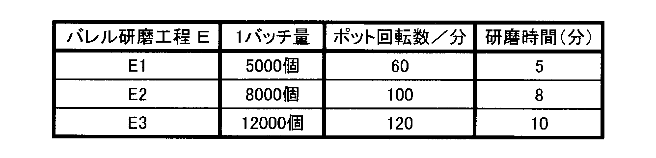
- the pot capacity is 10 to 15 liters, and 4000 to 15000 pieces of Mo sintered body are filled into a pot in one batch, and further, the number of revolutions is set with abrasives and water. Defects such as burrs are removed by performing barrel polishing for about 3 to 10 minutes while rotating the pot at 60 to 130 / min. After the barrel polishing process, the barrel polishing body is dried.
- the barrel polishing body When the brazing material surface has a wavy shape by pressing, it can be made flat.
- the barrel polishing described above is effective for removing burrs formed on the outer peripheral surface of the Mo sintered body (end hat), but it is sufficiently effective for removing burrs on the inner surface where there are burrs on the surface of the brazing material. Cannot be obtained.
- the abrasive is small, burrs may occur in the brazing material due to the barrel polishing process.
- the brazing material is deburred, it is predicted that the absolute amount of the brazing material will be insufficient, which may adversely affect the brazing operation of the filament in a subsequent process.
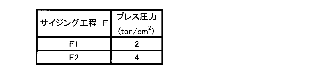
- the pressing pressure for carrying out this sizing is arbitrary, but the pressing pressure is preferably 6 ton / cm 2 or less (588 MPa or less).
- press oil lubricating oil
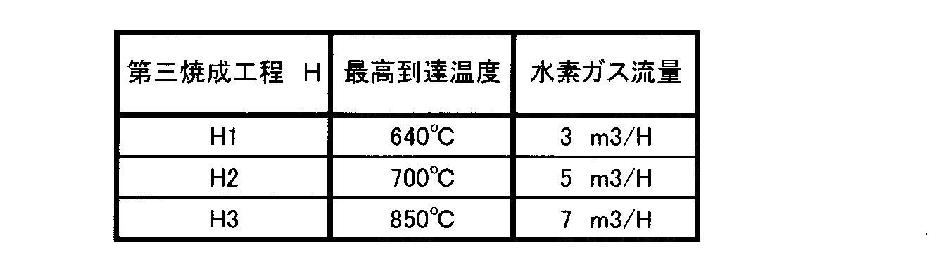
- a third baking step of heat treating the degreased product When barrel polishing, sizing, or press oil degreasing is performed, the end hat may be oxidized. Therefore, it is preferable to perform a step of removing surface oxide by heat treatment in a hydrogen atmosphere.
- the heat treatment is preferably carried out in a hydrogen gas stream with a maximum temperature of 600 to 900 ° C. If the temperature is less than 600 ° C., it takes time until the oxide removing effect is exhibited. On the other hand, if the temperature exceeds 900 ° C., no further effect can be obtained, which causes an increase in manufacturing cost.
- the end hat for magnetrons can be manufactured efficiently with high yield. Further, for example, when the firing operation is performed in a state where the firing boats are stacked in multiple stages as shown in FIG. 3, 200 or more Mo molded bodies per batch can be sintered simultaneously.
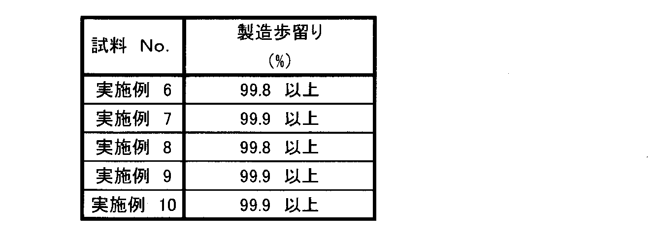
- the manufacturing yield can be increased to 80% or more even when 200 or more treatments are performed per batch.
- the manufacturing yield can be improved to 99% or more by performing barrel processing, press processing (sizing), degreasing, and a third firing step thereafter.
- Example 5 A high-purity Mo powder having an average particle size of 3 ⁇ m and a purity of 99.9% or more was prepared. As a result of investigating the impurity element amount of the high-purity Mo powder, the impurity element (nonvolatile component) was 0.08% by mass or less. Each impurity element component has an Al content of 0.005 mass% or less, a Ca content of 0.003 mass% or less, a Cr content of 0.005 mass% or less, and a Cu content of 0.
- a Mo boat having a length of 320 mm ⁇ a width of 220 mm ⁇ a thickness of 15 mm was prepared as the firing boat 22 and 500 Mo molded bodies 20 were placed (the gap between the molded bodies was 1 mm or more). . 10 stages of firing boats 22 were stacked on the firing container 21 through the separator 23 (5000 pieces per batch). This was put into a push-type firing furnace and fired under the firing conditions shown in Table 2. In charging, the inside of the furnace was replaced with nitrogen gas, and then a predetermined amount of wet hydrogen gas shown in Table 2 was supplied.
- Step C Second firing step
- the 2nd baking process was implemented on the baking conditions shown in Table 3.
- FIG. in the second firing step firing boats similar to those in the first firing step were stacked and placed in a firing container.
- the firing container was put into a push-type second firing furnace. In firing, the furnace was replaced with nitrogen gas, and then the hydrogen gas flow rate was adjusted.
- the main parts of the magnetron end hats according to Examples 1 to 5 were prepared by combining the molding process A, the first firing process B, and the second firing process C shown in Tables 1 to 3 as follows. .
- Example 1 A1 ⁇ B1 ⁇ C1
- Example 2 A1 ⁇ B2 ⁇ C2 -Example 3: A2->B2-> C2
- Example 4 A2 ⁇ B3 ⁇ C3
- Example 5 A3 ⁇ B4 ⁇ C4
- the process B4 of the example 5 was processed in a process in which the wet hydrogen gas was changed to the hydrogen gas to prepare a magnetron end hat according to the comparative example 1.
- the density of the Mo sintered body (end hat) and the production yield were measured. Further, the carbon content (wt. Ppm) in the surface region (region from the surface to a depth of 100 ⁇ m) and the central region (region of ⁇ 100 ⁇ m from the center point (W / 2) of the thickness W of the side wall) was measured. .
- the density was measured by the Archimedes method.
- the production yield was determined by measuring the ratio of non-defective products per 5000 batches.
- the carbon content was measured by a high frequency combustion-infrared absorption method. The measurement results are shown in Table 4 below.
- the magnetron end hats according to the respective examples had a density of 9.6 g / cm 3 or more and a production yield of 90% or more. Further, the end hat according to each example had a carbon content (carbon content) in the surface region lower than that in the central region.
- Mo—Ru brazing paste Mo: 57 wt%, Ru: 43 wt%, impurity carbon is 0.05 wt% or less, Fe is 0.009 wt% or less, Ni is 0.007 wt% or less at a predetermined position of the end hat.
- the center lead 5, the side lead 6, and the coiled filament 1 were brazed to produce a cathode assembly. This was incorporated into a vacuum tube to form a magnetron. A microwave oven was constructed using this magnetron, and the lifetime was measured. The lifetime was measured by measuring the presence or absence of erosion in the Mo sintered body (end hat surface) after 1000 sets and 10,000 sets after 1500 W ⁇ 5 minutes as one set. The results are shown in Table 5.
- Step D1 A step of placing a pre-sintered Mo—Ru brazing material was placed between the first firing step (Step B) and the second firing step (Step C).
- Step D2 After Step C, a pre-sintered Mo—Ru brazing material was placed and then joined by laser irradiation.
- Step G Degreasing
- Step G 3rd baking process
- the brazing material disposing step D, the barrel polishing step E, the sizing step F, the degreasing step G, and the third firing step H shown in Tables 6 to 8 are performed as follows.
- magnetron end hats according to Examples 6 to 10 were prepared.
- Example 6 Example 2 ⁇ (Process D1) ⁇ Process E1 ⁇ Process F1 ⁇ Process G ⁇ Process H3
- Example 7 Example 2 ⁇ (Process D1) ⁇ Process E2 ⁇ Process F1 ⁇ Process G ⁇ Process H1
- Example 8 Example 2 ⁇ Step D2 ⁇ Step E3 ⁇ Step F2 ⁇ Step G ⁇ Step H2
- Example 9 Example 3 ⁇ Step D2 ⁇ Step E2 ⁇ Step F1 ⁇ Step G ⁇ Step H1
- Example 10 Example 3 ⁇ Step E3 ⁇ Step G ⁇ Step H2 ⁇ Brazer Paste Application Drying
- Table 9 The production yield of the magnetron end hats according to Examples 6 to 10 was measured in the same manner as in Example 1. The measurement results are shown in Table 9 below.
- the manufacturing yield can be significantly improved even when various methods are applied as the brazing material arranging step D.
- the carbon content of the surface region of the end hat according to each example there was no change from the state of Example 2 and Example 3. Therefore, it was confirmed that the end hats according to Examples 6 to 10 have high long-term reliability.
- the magnetron end hat of the present invention since there is little residual carbon in the surface area of the Mo end hat, it is less likely to be sputtered when used as a magnetron. Can be obtained. Moreover, according to the manufacturing method of the end hat which concerns on this invention, the end hat of this invention can be manufactured efficiently with a sufficient yield.
Landscapes
- Microwave Tubes (AREA)
Abstract
Description
次に本発明について、以下の実施例を参照して具体的に説明する。
平均粒径が3μmであり、純度が99.9%以上である高純度Mo粉末を用意した。この高純度Mo粉末の不純物元素量を調査した結果、不純物元素(不揮発成分)が0.08質量%以下であった。各不純物元素成分は、Al含有量が0.005質量%以下であり、Ca含有量が0.003質量%以下であり、Cr含有量が0.005質量%以下であり、Cu含有量が0.002質量%以下であり、Fe含有量が0.03質量%以下であり、Mg含有量が0.002質量%以下であり、Mn含有量が0.002質量%以下であり、Ni含有量が0.008質量%以下であり、Pb含有量が0.002質量%以下であり、Si含有量が0.005質量%以下であり、Sn含有量が0.002質量%以下であり、炭素含有量が0.01質量%以下であった。
次に、Mo粉末を樹脂バインダ(PVA)と混合して造粒して、成形型に充填してプレス成形した。プレス圧力(成形圧力)は、表1に示す通りとした。なお、成形体のサイズは、エンドハットの直径Lが7.5mm×厚さがT2.5mm、内径が3.3mmであり、ろう材を載せる箇所の内径は3.9mmとした。

図3に示すように、焼成ボート22として、縦320mm×横220mm×厚さ15mmのMoボートを用意し、Mo成形体20を500個載置した(成形体同士の隙間は1mm以上あけた)。セパレータ23を介し、焼成ボート22を10段重ねて焼成用容器21に配置した(1バッチ5000個)。これをプッシュ式の焼成炉に投入し、表2に示す焼成条件にて焼成した。投入にあたっては炉内を窒素ガスで置換した後、ウエット水素ガスを表2に示す所定量を供給した。
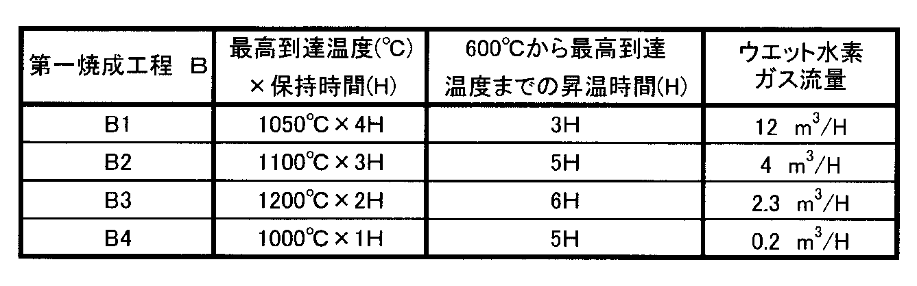
上記のように調製した第一の焼成体について、表3に示す焼成条件により、第二焼成工程を実施した。なお、第二焼成工程は第一焼成工程と同様の焼成ボートを積層して焼成用容器に配置した。焼成用容器ごとプッシュ式の第二の焼成炉に投入した。また、焼成にあたっては炉内を窒素ガスに置換してから後に、水素ガス流量を調製した。

・実施例2:A1→B2→C2
・実施例3:A2→B2→C2
・実施例4:A2→B3→C3
・実施例5:A3→B4→C4
また、比較例1として実施例5の工程B4をウエット水素ガスから水素ガスに変えた工程で処理して比較例1に係るマグネトロン用エンドハットを調製した。


次に、さらに製造歩留りを高める方法として次の工程を組み込んだ実施例を説明する。
ろう材配置工程として次の工程を行った。
各マグネトロン用エンドハットを研磨材および水と混合して、下記表6に示す条件(1バッチ量、ポット回転数、研磨時間)でバレル研磨工程を実施した。
工程Eを実施した各マグネトロン用エンドハットを下記表7に示すプレス圧力を掛けてろう材の型崩れを修正するサイジング工程を実施した。なお、プレス圧力を掛けるに際して金型には潤滑油を塗布した。
工程Fを実施した各マグネトロン用エンドハットを脱脂して潤滑油を除去して脱脂工程を実施した。
工程Gを実施した各マグネトロン用エンドハットを下記表8に示す条件で焼成し第3焼成工程を実施した。
実施例2→(工程D1)→工程E1→工程F1→工程G→工程H3
実施例7:
実施例2→(工程D1)→工程E2→工程F1→工程G→工程H1
実施例8:実施例2→工程D2→工程E3→工程F2→工程G→工程H2
実施例9:実施例3→工程D2→工程E2→工程F1→工程G→工程H1
実施例10:
実施例3→工程E3→工程G→工程H2→ろう材ペースト塗布乾燥
実施例6~10に係るマグネトロン用エンドハットについて、その製造歩留りを実施例1と同様に測定した。その測定結果を下記表9に示す。
5…センターリード
6…サイドリード
7…センターリード取付穴部
8…エンドハットとろう材の接合底面部
9…エンドハットとろう材の接合側面部
10…厚さ方向の中心点
11…表面領域
12…中心領域
20…Mo成形体
21…焼成用容器
22…焼成ボート
23…セパレータ
S…表面
Claims (14)
- Mo焼結体から成るマグネトロン用エンドハットにおいて、Mo焼結体の表面から100μmまでの表面領域の炭素含有量が30ppm以下であり、上記Mo焼結体の厚さ方向の中心点から±100μm以内の中心領域の炭素含有量が50~300ppmであることを特徴とするマグネトロン用エンドハット。
- 前記Mo焼結体の密度が9.6~10.0g/cm3であることを特徴とする請求項1記載のマグネトロン用エンドハット。
- 前記Mo焼結体は、Mo含有量が99.9質量%以上であり、かつ不純物元素として、Al含有量が0.005質量%以下であり、Ca含有量が0.003質量%以下であり、Cr含有量が0.005質量%以下であり、Cu含有量が0.002質量%以下であり、Fe含有量が0.03質量%以下であり、Mg含有量が0.002質量%以下であり、Mn含有量が0.002質量%以下であり、Ni含有量が0.008質量%以下であり、Pb含有量が0.002質量%以下であり、Si含有量が0.005質量%以下であり、Sn含有量が0.002質量%以下であることを特徴とする請求項1または請求項2に記載のマグネトロン用エンドハット。
- Mo-Ruろう材が設けられていることを特徴とする請求項1ないし請求項3のいずれか1項に記載のマグネトロン用エンドハット。
- 前記Mo-Ru系ろう材は、不純物元素として、炭素含有量が0.05質量%以下であり、Fe含有量が0.009質量%以下であり、Ni含有量が0.007質量%以下であることを特徴とする請求項4記載のマグネトロン用エンドハット。
- 請求項1ないし請求項5のいずれか1項に記載のマグネトロン用エンドハットを用いたことを特徴とするマグネトロン。
- 純度99.9質量%以上であるMo粉と樹脂バインダーとを用いてエンドハット形状のMo成形体をプレス成形するプレス工程と、このMo成形体を酸化還元雰囲気中で焼成して第一の焼成体を得る第一焼成工程と、この第一の焼成体を還元雰囲気中で焼成して第二の焼成体を得る第二の焼成工程とを具備することを特徴とするマグネトロン用エンドハットの製造方法。
- 前記酸化還元雰囲気がウエット水素ガスであることを特徴とする請求項7記載のマグネトロン用エンドハットの製造方法。
- 前記第一焼成工程は、ウエット水素ガス流量が0.2m3/時間以上であり、最高到達温度が1000~1200℃であり、この最高到達温度での保持時間が1~4時間である条件下で実施されることを特徴とする請求項7または請求項8記載のマグネトロン用エンドハットの製造方法。
- 前記第一焼成工程は、温度600℃から最高到達温度までを3~7時間かけて昇温することを特徴とする請求項7ないし請求項9のいずれか1項に記載のマグネトロン用エンドハットの製造方法。
- 前記第二焼成工程は、水素ガス流量が0.2m3/時間以上であり、最高到達温度が1600~1900℃であり、最高到達温度での保持時間が30分~5時間である条件下で実施されることを特徴とする請求項7ないし請求項10のいずれか1項に記載のマグネトロン用エンドハットの製造方法。
- 前記第二の焼成体にバレル研磨加工を施すことによりバレル研磨体を得ることを特徴とする請求項7ないし請求項11のいずれか1項に記載のマグネトロン用エンドハットの製造方法。
- 前記バレル研磨体をプレス加工することを特徴とする請求項12記載のマグネトロン用エンドハットの製造方法。
- 得られたマグネトロン用エンドハットは、Mo焼結体の表面から100μmまでの表面領域の炭素含有量を30ppm以下とする一方、Mo焼結体の厚さ方向の中心点から±100μm以内の中心領域の炭素含有量を100~300ppmとすることを特徴とする請求項7記載のマグネトロン用エンドハットの製造方法。
Priority Applications (3)
| Application Number | Priority Date | Filing Date | Title |
|---|---|---|---|
| CN201180035073.9A CN103003909B (zh) | 2010-07-16 | 2011-07-15 | 用于磁控管的端帽、其制造方法以及磁控管 |
| KR1020137001043A KR101368145B1 (ko) | 2010-07-16 | 2011-07-15 | 마그네트론용 엔드헷, 그의 제조방법, 및 마그네트론 |
| JP2012524611A JP5814236B2 (ja) | 2010-07-16 | 2011-07-15 | マグネトロン用エンドハットおよびその製造方法並びにマグネトロン |
Applications Claiming Priority (2)
| Application Number | Priority Date | Filing Date | Title |
|---|---|---|---|
| JP2010-162202 | 2010-07-16 | ||
| JP2010162202 | 2010-07-16 |
Publications (1)
| Publication Number | Publication Date |
|---|---|
| WO2012008580A1 true WO2012008580A1 (ja) | 2012-01-19 |
Family
ID=45469574
Family Applications (1)
| Application Number | Title | Priority Date | Filing Date |
|---|---|---|---|
| PCT/JP2011/066243 Ceased WO2012008580A1 (ja) | 2010-07-16 | 2011-07-15 | マグネトロン用エンドハットおよびその製造方法並びにマグネトロン |
Country Status (5)
| Country | Link |
|---|---|
| JP (1) | JP5814236B2 (ja) |
| KR (1) | KR101368145B1 (ja) |
| CN (1) | CN103003909B (ja) |
| MY (1) | MY157350A (ja) |
| WO (1) | WO2012008580A1 (ja) |
Families Citing this family (1)
| Publication number | Priority date | Publication date | Assignee | Title |
|---|---|---|---|---|
| CN106531597B (zh) * | 2016-12-29 | 2019-04-02 | 广东威特真空电子制造有限公司 | 磁控管及其阴极组件以及制造磁控管的阴极组件的方法 |
Citations (7)
| Publication number | Priority date | Publication date | Assignee | Title |
|---|---|---|---|---|
| JPS62208527A (ja) * | 1986-03-07 | 1987-09-12 | Toho Kinzoku Kk | マグネトロン用エンドハツトの製法 |
| JPS6417354A (en) * | 1987-07-13 | 1989-01-20 | Hitachi Ltd | Magnetron |
| JPH01156449A (ja) * | 1987-12-11 | 1989-06-20 | Tokyo Tungsten Co Ltd | モリブデン焼結体及びその製造方法 |
| JPH08339768A (ja) * | 1994-05-10 | 1996-12-24 | Tokyo Tungsten Co Ltd | ろう付け用リング |
| JPH1083765A (ja) * | 1996-07-15 | 1998-03-31 | Toshiba Corp | マグネトロン用エンドハット部品およびその製造方法 |
| JPH11335705A (ja) * | 1998-05-28 | 1999-12-07 | Toshiba Corp | 焼結部品の製造方法 |
| JP2000173483A (ja) * | 1998-12-03 | 2000-06-23 | Matsushita Electronics Industry Corp | マグネトロン用陰極部及びそれを用いたマグネトロン装置 |
Family Cites Families (5)
| Publication number | Priority date | Publication date | Assignee | Title |
|---|---|---|---|---|
| JPS58157593A (ja) * | 1982-03-12 | 1983-09-19 | Tokyo Tungsten Co Ltd | 高融点難溶性金属部品への鑞着方法 |
| JPS6086731A (ja) * | 1983-10-18 | 1985-05-16 | Tokyo Tungsten Co Ltd | マグネトロン用部品の製造方法 |
| KR980011615A (ko) * | 1996-07-15 | 1998-04-30 | 원본미기재 | 마그네트론용 엔드 햇 부품 및 그 제조방법 |
| JP4667441B2 (ja) * | 2007-10-31 | 2011-04-13 | 東芝ホクト電子株式会社 | ろう材、管球、マグネトロンおよびろう付け方法 |
| KR100925015B1 (ko) * | 2008-02-29 | 2009-11-04 | 안의현 | 마그네트론 음극 구조체 융착체 및 그 제조방법 |
-
2011
- 2011-07-15 CN CN201180035073.9A patent/CN103003909B/zh active Active
- 2011-07-15 KR KR1020137001043A patent/KR101368145B1/ko active Active
- 2011-07-15 MY MYPI2012701313A patent/MY157350A/en unknown
- 2011-07-15 WO PCT/JP2011/066243 patent/WO2012008580A1/ja not_active Ceased
- 2011-07-15 JP JP2012524611A patent/JP5814236B2/ja active Active
Patent Citations (7)
| Publication number | Priority date | Publication date | Assignee | Title |
|---|---|---|---|---|
| JPS62208527A (ja) * | 1986-03-07 | 1987-09-12 | Toho Kinzoku Kk | マグネトロン用エンドハツトの製法 |
| JPS6417354A (en) * | 1987-07-13 | 1989-01-20 | Hitachi Ltd | Magnetron |
| JPH01156449A (ja) * | 1987-12-11 | 1989-06-20 | Tokyo Tungsten Co Ltd | モリブデン焼結体及びその製造方法 |
| JPH08339768A (ja) * | 1994-05-10 | 1996-12-24 | Tokyo Tungsten Co Ltd | ろう付け用リング |
| JPH1083765A (ja) * | 1996-07-15 | 1998-03-31 | Toshiba Corp | マグネトロン用エンドハット部品およびその製造方法 |
| JPH11335705A (ja) * | 1998-05-28 | 1999-12-07 | Toshiba Corp | 焼結部品の製造方法 |
| JP2000173483A (ja) * | 1998-12-03 | 2000-06-23 | Matsushita Electronics Industry Corp | マグネトロン用陰極部及びそれを用いたマグネトロン装置 |
Also Published As
| Publication number | Publication date |
|---|---|
| MY157350A (en) | 2016-05-31 |
| CN103003909B (zh) | 2015-08-19 |
| KR20130020921A (ko) | 2013-03-04 |
| JP5814236B2 (ja) | 2015-11-17 |
| KR101368145B1 (ko) | 2014-02-27 |
| JPWO2012008580A1 (ja) | 2013-09-09 |
| CN103003909A (zh) | 2013-03-27 |
Similar Documents
| Publication | Publication Date | Title |
|---|---|---|
| JP5341049B2 (ja) | セラミックス焼結体の製造方法、セラミックス焼結体およびセラミックスヒータ | |
| TWI439337B (zh) | Sintered body and sintered body | |
| JP2010514921A (ja) | スパッタリングターゲット修復用の方法 | |
| JP3917208B2 (ja) | タングステン−モリブデン合金製ルツボ及びその製造方法 | |
| JP5450059B2 (ja) | マグネトロン用ステムおよびそれを用いたマグネトロン並びにマグネトロン用ステムの製造方法 | |
| WO2025086823A1 (zh) | 一种钨合金丝及其制备方法和用途、碳化钨合金灯丝 | |
| JP5814236B2 (ja) | マグネトロン用エンドハットおよびその製造方法並びにマグネトロン | |
| US5118332A (en) | Composite brazed spinner | |
| JP5814228B2 (ja) | マグネトロン用エンドハットおよびその製造方法並びにマグネトロン | |
| JP6037217B2 (ja) | 窒化珪素質焼結体の製造方法 | |
| JP5187579B2 (ja) | 炭化珪素発熱体端部の製造方法 | |
| JP5285868B2 (ja) | マグネトロン用ステムの製造方法 | |
| WO2020213033A1 (ja) | プラズマ電極用の炭化ハフニウム粉末、その製造方法、炭化ハフニウム焼結体及びプラズマ電極 | |
| JP2019009021A (ja) | セラミックス部材及びその製造方法 | |
| JP6307121B2 (ja) | LiCoO2を含有する焼結体および円筒形スパッタリングターゲット | |
| JP3402191B2 (ja) | 放電ランプ用陰極の製造方法 | |
| JPH10310841A (ja) | セラミックコーティング材料,その製造方法および同材料を用いた高温部材 | |
| JP4476662B2 (ja) | マトリックス材料の製造方法ならびにマトリックス型陰極構体およびその製造方法 | |
| JP2017137569A (ja) | Cu−Ga合金スパッタリングターゲットの製造方法、及び、Cu−Ga合金スパッタリングターゲット | |
| JP2021044088A (ja) | マグネトロン用セラミックス部品およびその製造方法 | |
| JP2026505917A (ja) | 炭化タングステン合金フィラメントおよびその製造方法、加熱デバイス | |
| JP2001115228A (ja) | タングステンモリブデン合金 | |
| JPH05314868A (ja) | 真空インタラプタ用電極の製造方法 | |
| JP2008108579A (ja) | 冷陰極蛍光ランプ用電極 | |
| JPH03272124A (ja) | タンタルコンデンサ用リード線 |
Legal Events
| Date | Code | Title | Description |
|---|---|---|---|
| 121 | Ep: the epo has been informed by wipo that ep was designated in this application |
Ref document number: 11806910 Country of ref document: EP Kind code of ref document: A1 |
|
| WWE | Wipo information: entry into national phase |
Ref document number: 2012524611 Country of ref document: JP |
|
| ENP | Entry into the national phase |
Ref document number: 20137001043 Country of ref document: KR Kind code of ref document: A |
|
| NENP | Non-entry into the national phase |
Ref country code: DE |
|
| WWE | Wipo information: entry into national phase |
Ref document number: 1201006850 Country of ref document: TH |
|
| 122 | Ep: pct application non-entry in european phase |
Ref document number: 11806910 Country of ref document: EP Kind code of ref document: A1 |