WO2012008107A1 - 位相ずれ検出装置、モータ駆動装置、およびブラシレスモータ、並びに位相ずれ検出方法 - Google Patents
位相ずれ検出装置、モータ駆動装置、およびブラシレスモータ、並びに位相ずれ検出方法 Download PDFInfo
- Publication number
- WO2012008107A1 WO2012008107A1 PCT/JP2011/003747 JP2011003747W WO2012008107A1 WO 2012008107 A1 WO2012008107 A1 WO 2012008107A1 JP 2011003747 W JP2011003747 W JP 2011003747W WO 2012008107 A1 WO2012008107 A1 WO 2012008107A1
- Authority
- WO
- WIPO (PCT)
- Prior art keywords
- phase shift
- phase
- timing
- signal
- motor
- Prior art date
Links
Images


Classifications
-
- H—ELECTRICITY
- H02—GENERATION; CONVERSION OR DISTRIBUTION OF ELECTRIC POWER
- H02P—CONTROL OR REGULATION OF ELECTRIC MOTORS, ELECTRIC GENERATORS OR DYNAMO-ELECTRIC CONVERTERS; CONTROLLING TRANSFORMERS, REACTORS OR CHOKE COILS
- H02P6/00—Arrangements for controlling synchronous motors or other dynamo-electric motors using electronic commutation dependent on the rotor position; Electronic commutators therefor
- H02P6/14—Electronic commutators
- H02P6/16—Circuit arrangements for detecting position
- H02P6/18—Circuit arrangements for detecting position without separate position detecting elements
- H02P6/182—Circuit arrangements for detecting position without separate position detecting elements using back-emf in windings
-
- H—ELECTRICITY
- H02—GENERATION; CONVERSION OR DISTRIBUTION OF ELECTRIC POWER
- H02P—CONTROL OR REGULATION OF ELECTRIC MOTORS, ELECTRIC GENERATORS OR DYNAMO-ELECTRIC CONVERTERS; CONTROLLING TRANSFORMERS, REACTORS OR CHOKE COILS
- H02P6/00—Arrangements for controlling synchronous motors or other dynamo-electric motors using electronic commutation dependent on the rotor position; Electronic commutators therefor
- H02P6/14—Electronic commutators
- H02P6/16—Circuit arrangements for detecting position
- H02P6/18—Circuit arrangements for detecting position without separate position detecting elements
- H02P6/188—Circuit arrangements for detecting position without separate position detecting elements using the voltage difference between the windings
Definitions
- the present invention relates to a phase shift detection device that detects a motor drive phase shift based on a shift in the arrangement of a magnetic pole position sensor disposed in a motor, a motor drive device and a brushless motor including the same, and a phase shift detection method.
- Patent Document 1 A technique for detecting such a motor drive phase shift and a motor using the technique have been disclosed in, for example, Patent Document 1.
- a detection position error due to the positional shift is generated.
- accurate rotation control of the brushless motor cannot be performed, and there is a problem that, for example, rotation efficiency is reduced.
- the phase difference between the sensor signal from the magnetic pole position sensor and the back EMF signal including the local minimum value from the motor drive circuit is calculated, so that The alignment error is determined. That is, first, the brushless motor is elliptically moved with the motor driving stopped. During this elliptical period, the sensor signal and the back EMF signal are measured. Then, the phase of the local minimum value of the back EMF signal and the phase of the pulse change point of the sensor signal are obtained, and the alignment error is determined from these phase differences. Further, the detected position of the rotor is corrected by accumulating the phase difference and correcting the sensor signal based on the phase difference.
- Patent Document 2 a method has been proposed in which a phase shift amount from an ideal position is detected using a comparator and the energization timing is corrected (see, for example, Patent Document 2). That is, in Patent Document 2, the W-phase induced voltage is detected by a comparator, and the mutual phase difference is detected from the output signal of the comparator and the detection signal from the U-phase Hall element.
- the phase shift detection device of the present invention uses a pulse-like position detection signal based on a sensor signal of a magnetic pole position sensor arranged in a motor and a measurement signal based on an induced voltage from a winding that drives the motor. Detecting phase shift.
- the phase shift detection device includes a level difference calculation unit that calculates a level difference between the level of the measurement signal at the rising timing of the position detection signal and the level of the measurement signal at the falling timing, and a phase based on the level difference. And a phase shift calculator that calculates the amount of shift.
- a motor drive device includes the phase shift detection device and a drive phase correction unit that corrects a phase shift of the motor drive based on the phase shift amount calculated by the phase shift calculation unit. is there.
- the brushless motor of the present invention includes a rotor that holds a permanent magnet and is arranged to be rotatable around a rotation axis, a stator in which windings for each phase are wound around a stator core having a plurality of salient poles, It is the structure provided with the said motor drive device.
- This configuration makes it possible to realize a brushless motor having a function of correcting a phase shift of the motor drive with a simple configuration.
- the phase shift detection method of the present invention uses a pulse-shaped position detection signal based on a sensor signal of a magnetic pole position sensor arranged in a motor and a measurement signal based on an induced voltage from a winding that drives the motor, This is a phase shift detection method for detecting a motor drive phase shift.
- a level difference between the level of the measurement signal at the rising timing of the position detection signal and the level of the measurement signal at the falling timing is calculated, and the phase shift amount is calculated based on the level difference.
- FIG. 1 is a block diagram of a brushless motor including a phase shift detection device according to Embodiment 1 of the present invention.
- FIG. 2 is a diagram showing waveforms of a measurement signal and a position detection signal supplied to the phase shift detector.
- FIG. 3 is a block diagram of a brushless motor including the phase shift detection device according to Embodiment 2 of the present invention.
- FIG. 4A is a timing chart of a measurement signal, an acquisition timing signal, and a sensor signal when each position sensor is arranged at a normal position in the same phase shift detection device.
- FIG. 4B is a timing chart of a measurement signal, an acquisition timing signal, and a sensor signal when each position sensor is not arranged at a normal position in the same phase shift detection device.
- FIG. 4A is a timing chart of a measurement signal, an acquisition timing signal, and a sensor signal when each position sensor is not arranged at a normal position in the same phase shift detection device.
- FIG. 5 is a diagram illustrating a method of calculating phase shift data calculated by the phase shift calculation unit in the phase shift detection device.
- FIG. 6 is a block diagram of a brushless motor including the phase shift detection device according to the third embodiment of the present invention.
- FIG. 7 is a block diagram of a feedback loop configured in the same phase shift detection device.
- FIG. 8 is a block diagram of a brushless motor including the phase shift detection device according to the fourth embodiment of the present invention.
- FIG. 9 is a diagram for explaining processing of the phase shift detection unit and the phase shift correction unit of the phase shift detection device.
- FIG. 10 is a block diagram of a brushless motor including the phase shift detection device according to the fifth embodiment of the present invention.
- FIG. 11 is a diagram illustrating waveforms of a measurement signal and a position detection signal in the same phase shift detection device.
- FIG. 12 is a diagram showing a cross-sectional structure of a brushless motor including the motor drive device according to Embodiment 6 of the present invention.
- FIG. 13 is a view showing the inside of the brushless motor from above.
- FIG. 14 is a view showing the inside of the brushless motor from above.
- FIG. 15 is a block diagram of the brushless motor.
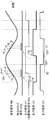
- FIG. 16 is a diagram showing the timing of the induced voltage and the sensor signal when the rotor rotates in a non-driven state when each of the position sensors of the brushless motor is arranged in a normal state.
- FIG. 12 is a diagram showing a cross-sectional structure of a brushless motor including the motor drive device according to Embodiment 6 of the present invention.
- FIG. 13 is a view showing the inside of the brushless motor from above.
- FIG. 14 is a view showing the inside
- FIG. 17 is a diagram illustrating an example when a mounting position shift of the position sensor of the brushless motor occurs.
- FIG. 18 is a diagram showing the timing of the induced voltage and the sensor signal when the rotor rotates in a non-driven state when the mounting position shift of the position sensor of the brushless motor occurs.
- FIG. 19 is a block diagram of a brushless motor including the phase shift detection device according to the seventh embodiment of the present invention.
- FIG. 20 is a flowchart showing a procedure of processing for generating correction data of the brushless motor.
- phase shift detection device a phase shift detection device, a motor drive device, a brushless motor, and a phase shift detection method according to an embodiment of the present invention will be described with reference to the drawings.
- FIG. 1 is a block diagram of a brushless motor including a phase shift detection device 30 according to Embodiment 1 of the present invention.
- the brushless motor includes a motor 10 having a winding 11, a position sensor 12 as a magnetic pole position sensor that detects the rotational position of the rotor of the motor 10, and a motor driving device that drives the motor 10. 20. Further, a power source 29 is connected to the motor driving device 20 in order to supply electric power.
- motor 10 includes a rotor that is rotatably arranged around a rotation axis, and a stator in which winding 11 for each phase is wound around a stator core, and U phases that are 120 degrees out of phase with each other.
- An example of a brushless motor driven in three phases, V phase and W phase will be described.
- a U-phase winding 11u, a V-phase winding 11v, and a W-phase winding 11w are wound around the stator of the motor 10. Then, a Y connection is made such that one end of each winding is connected at a neutral point, and an energization signal for driving the winding is supplied from the motor driving device 20 to the other end of each winding.
- the brushless motor also includes a U-phase position sensor 12u, a V-phase position sensor 12v, and a W-phase position sensor 12w as position sensors 12 such as Hall sensors in order to detect the position of each phase. I have. Then, a sensor signal Hs indicating the detected position is supplied from each position sensor 12 to the motor driving device 20.
- the motor drive device 20 includes an inverter 21, a phase shift detection device 30, and a drive control circuit 40.
- the drive control circuit 40 is notified of rotation command data Rr for instructing a rotation speed, a rotation position, and the like from an external host device, for example. Further, the drive control circuit 40 is supplied with the sensor signal Hs from the position sensor 12u, the sensor signal H2 from the position sensor 12v, and the sensor signal H3 from the position sensor 12w as the sensor signal Hs. Deviation data dP is supplied. The drive control circuit 40 generates rotational position data indicating the rotational position of the rotor based on the sensor signal Hs. At this time, the drive control circuit 40 corrects the rotational position detected from the sensor signal Hs based on the phase shift data dP, and generates rotational position data.
- the drive control circuit 40 further provides a pulse for driving the inverter 21 based on the deviation amount between the rotation command data Rr and the rotation position data or the deviation amount between the rotation command data Rr and the rotation speed data generated based on the rotation position data.
- the driving pulse signal Pwm having a shape is generated.
- the inverter 21 energizes the winding 11 for each phase based on the drive pulse signal Pwm to drive the winding 11.
- the inverter 21 includes a switch element 22 connected to the positive electrode Vcc side of the power supply 29 and a switch element 22 connected to the ground GND side serving as a negative electrode for each of the U phase, the V phase, and the W phase. Further, the opposite power supply sides of the switch elements 22 on the positive electrode side and the negative electrode side are connected to each other, and an energization signal for energizing and driving the winding 11 is output from this connection portion via the drive output terminal.
- a U-phase energization signal U is transmitted from the drive output terminal Du to the winding 11u
- a V-phase energization signal V is transmitted from the drive output terminal Dv to the coil 11v
- a W-phase energization signal W is transmitted from the drive output terminal Dw to the winding 11v. 11w.
- an energization drive current flows from the power source 29 to the winding 11 via the on switch element 22.
- a feedback control loop is formed that controls the rotational speed and rotational position of the rotor in accordance with the rotation command data Rr.
- the brushless motor according to the present embodiment compensates for the influence on the position detection due to, for example, mounting position shift of the position sensors 12u, 12v, 12w on the circuit board or mounting position shift of the circuit board.
- a deviation detection device 30 is provided.
- the phase shift detection device 30 uses a pulse-like position detection signal based on the sensor signal Hs of the position sensor 12 disposed in the motor 10 and a measurement signal Ms based on an induced voltage from the winding 11 that drives the motor 10. Detecting the phase shift of the motor drive.
- the phase shift detection device 30 includes a measurement signal generation unit 31, a level difference calculation unit 32, and a phase shift calculation unit 33.
- the phase shift detection device 30 is supplied with one phase of the three sensor signals Hs and is connected to two of the three drive output terminals Du, Dv, and Dw. In FIG.
- the sensor signal H1 is directly supplied to the level difference calculation unit 32 as the position detection signal Rd, and the bias voltage Vb generated by the measurement signal generation unit 31 is connected to the drive output terminal Du, and the drive output terminal Dw
- the phase shift detection device 30 detects a motor drive phase shift using an induced voltage generated from the winding 11. For this reason, the phase shift detection device 30 uses a period in which the motor 10 rotates in a non-driven state such as an elliptical state.
- the measurement signal generator 31 In the period in which the motor 10 rotates in the non-driven state, the measurement signal generator 31 generates the measurement signal Ms in order to detect a phase shift based on the induced voltage generated from the winding 11.
- the measurement signal Ms is a signal based on an induced voltage
- the measurement signal generation unit 31 includes a bias circuit that applies a bias voltage Vb to one phase winding in order to generate the measurement signal Ms.
- a series circuit of a resistor R1 and a resistor R2 as a bias circuit is provided between the positive electrode Vcc of the power supply 29 and the ground GND.
- the voltage divided by the resistors R1 and R2 is supplied as a bias voltage Vb to the winding 11u via the drive output terminal Du.
- the measurement signal generation unit 31 outputs an induced voltage generated from a winding of another phase different from the winding to which the bias voltage Vb is applied as the measurement signal Ms.
- the measurement signal generation unit 31 takes in the voltage waveform of the drive output terminal Dw to which the induced voltage generated from the winding 11w is supplied, and outputs this voltage waveform as the measurement signal Ms.
- 1 shows an example in which the measurement signal generator 31 outputs the voltage waveform of the drive output terminal Dw as the measurement signal Ms as it is, but the voltage waveform of the drive output terminal Dw has an amplitude suitable for measurement.
- the configuration may be such that the measurement signal Ms is converted and output via an amplification circuit or an attenuation circuit that converts the waveform signal.
- a sinusoidal induced voltage can be obtained from the drive output terminal of the other phase in the motor 10 that rotates in a non-driven state. it can.
- the phase shift is detected by using the sinusoidal induced voltage thus obtained, that is, the measurement signal Ms.
- the present embodiment uses the sinusoidal measurement signal Ms, there is an advantage that erroneous detection is less likely to occur compared to a waveform including a local minimum value.
- FIG. 2 is a diagram illustrating waveforms of the measurement signal Ms and the position detection signal Rd supplied to the phase shift detection device 30 according to the first embodiment of the present invention.
- the upper waveform in FIG. 2 shows the measurement signal Ms
- the lower waveform in FIG. 2 shows the position detection signal Rd.
- the position detection signal Rd is a pulse signal as shown in FIG.
- the level difference calculation unit 32 is supplied with two signals as shown in FIG.
- the level difference calculation unit 32 calculates a level difference between the level of the measurement signal Ms at the rising timing of the position detection signal Rd and the level of the measurement signal Ms at the falling timing.
- FIG. 2 shows an example in which the rise of the position detection signal Rd at the time t0 and the fall at the time t1 are used as the rise and fall timings of the position detection signal Rd.
- the level difference calculation unit 32 uses this timing to detect the level Lr of the measurement signal Ms at time t0 and the level Lf of the measurement signal Ms at time t1.
- the phase shift calculation unit 33 calculates the amount of phase shift based on the notified level difference data dL. That is, when the phase of the position detection signal Rd with respect to the measurement signal Ms changes, the level difference data dL also changes accordingly.
- the phase shift calculator 33 calculates a phase shift amount from the level difference data dL based on the change in the level difference data dL.
- the phase shift calculation unit 33 converts the phase shift amount into, for example, an electrical angle, and supplies it to the drive control circuit 40 as phase shift data dP.
- the drive control circuit 40 corrects the rotational position detected from the sensor signal Hs based on the phase shift data dP, and generates a corrected position signal.
- the timing of the peak value of the measurement signal Ms is set so as to coincide with the center timing of the pulse of the position detection signal Rd. Then, when the position sensor 12u is correctly disposed, the level of the measurement signal Ms at the time of rising and falling of the position detection signal Rd becomes equal, so that the level difference data dL becomes zero.
- the position sensor 12u is displaced, the phase of the position detection signal Rd with respect to the measurement signal Ms is also shifted according to the displacement. For example, the level Lr and the level Lf are different as shown in FIG. The magnitude of the level difference data dL changes substantially proportionally depending on the position where the position sensor 12u is disposed.
- the phase shift calculation unit 33 can calculate the phase shift amount using the phase where the level difference data dL is zero as the reference phase. Further, the phase advance or delay can be detected by the sign of the level difference data dL, and the amount of phase shift from the reference phase can be calculated according to the magnitude of the absolute value of the level difference data dL. Further, the phase shift detection device 30 calculates the phase shift amount based on the difference in the sine wave level at the timing of the change edge of the position detection signal Rd as described above. For this reason, even if the duty ratio of the position detection signal Rd, that is, the pulse width (t1-t0) shown in FIG. 2 changes, the change is canceled out by the difference, thereby improving the accuracy of phase shift detection. it can.
- the phase shift detection device 30 utilizes the level difference between the level of the measurement signal Ms at the rising timing of the position detection signal Rd and the level of the measurement signal Ms at the falling timing. A phase shift is detected. For this reason, for example, since it is not necessary to detect the phase of the local minimum value in the induced voltage waveform including the local minimum value, it is possible to detect the phase shift of the motor drive with a simple configuration.
- the example using the sinusoidal measurement signal Ms has been described, but the level during the voltage increase period and the level during the voltage decrease period in the induced voltage waveform including the local minimum value are described. It is also possible to adopt a configuration that captures at the change edge timing of the position detection signal Rd and calculates the phase shift amount based on the level difference.
- the phase shift detection device 30 of the present embodiment detects the phase shift using the measurement signal Ms based on the sinusoidal induced voltage. This is based on a level difference during a period in which the amount of change in the sine wave waveform is large, and the level difference changes almost proportionally to the phase shift. Can detect the deviation.
- the phase shift calculation unit can calculate the phase shift for each phase, and the drive control circuit can correct the phase shift for each phase.
- FIG. 2 shows an example in which the level difference is calculated using the edge change of one pulse of the position detection signal Rd.
- each level difference is calculated using the edge change of a plurality of pulses.
- the average value may be set as the level difference data dL. Thereby, the influence of noise or the like can be suppressed.
- phase difference between the level of the measurement signal Ms at the rising timing of the position detection signal Rd and the level of the measurement signal Ms at the falling timing is calculated, and the phase shift amount is calculated based on the level difference. Even with the detection method, it is possible to detect misalignment in the same manner while having the same effect. Such a phase shift detection method can be easily implemented by using, for example, a microcomputer described below.
- FIG. 3 is a block diagram of a brushless motor including the phase shift detection device 302 according to the second embodiment of the present invention.
- the brushless motor shown in FIG. 3 includes a phase shift detection device 302 provided in the motor driving device 202 and a capture timing generation unit 342, and a level difference.
- the calculation unit 322 and the phase shift calculation unit 332 perform processing different from that in the first embodiment.
- symbol is attached
- the phase shift detection device 302 uses the sensor signal Hs of the position sensor 12 disposed in the motor 10 and the measurement signal Ms based on the induced voltage from the winding 11 that drives the motor 10. Detect motor drive phase shift.
- the phase shift detection device 302 includes a measurement signal generation unit 31, a level difference calculation unit 322, a phase shift calculation unit 332, and a capture timing generation unit 342. Further, the phase shift detection device 302 is supplied with one phase of the three sensor signals Hs and is connected to two of the three drive output terminals Du, Dv, and Dw. In FIG.
- the sensor signal H2 is supplied to the capture timing generation unit 342, the bias voltage Vb generated by the measurement signal generation unit 31 is connected to the drive output terminal Du, and the signal at the drive output terminal Dw is the measurement signal.
- An example of supply to the level difference calculation unit 322 via the generation unit 31 is shown.
- the capture timing generation unit 342 uses the timing of the change edge of the sensor signal H2 as a reference for the rise and fall of the position detection signal Rd. The timing before and after that is generated. That is, for the rise and fall of the position detection signal Rd based on the sensor signal H1 described in the first embodiment, the timing before and after the rise and the timing before and after the fall are generated.
- each level of the measurement signal Ms is measured at these timings, and the level is captured as level data.
- the phase shift detection device 302 uses a period during which the motor 10 rotates in a non-driven state, and detects a phase shift using an induced voltage during that period.
- the sensor signal H2 is supplied to the capture timing generation unit 342.
- the capture timing generation unit 342 uses the sensor signal H2 to generate timings before and after the rising and falling of the position detection signal Rd based on the sensor signal H1.
- the timing generated by the acquisition timing generation unit 342 includes a plurality of timings at a certain period before and after the rising timing of the position detection signal Rd and a plurality of timings at a certain period before and after the timing of the falling of the position detection signal Rd. Is the timing.
- the generated timing is supplied to the level difference calculation unit 322 as a capture timing signal Smp.
- the level difference calculation unit 322 measures the level of the measurement signal Ms according to each timing indicated by the capture timing signal Smp, and captures the level as level data. Then, the level difference calculation unit 322 calculates a plurality of level differences at timings before and after the rise timing and fall timing of the position detection signal Rd using each level data taken in. The level difference calculation unit 322 supplies level difference data dL0 to dLn, which are calculated level differences, to the phase shift calculation unit 332.
- the phase shift calculation unit 332 obtains the timing at which the level difference becomes zero using the supplied plurality of level difference data dL0 to dLn. That is, the zero cross timing of the signal obtained by sequentially obtaining the level difference between the two points with respect to the measurement signal Ms is obtained. Then, the phase shift calculation unit 332 calculates the phase shift from the timing when the level difference becomes zero, and outputs it as the phase shift data dP.
- FIG. 4A and 4B are timing charts of the measurement signal Ms, the capture timing signal Smp, and the sensor signal Hs according to Embodiment 2 of the present invention.
- FIG. 5 is a diagram illustrating a method of calculating the phase shift data dP calculated by the phase shift calculation unit 332 according to Embodiment 2 of the present invention.
- the details of the phase shift detector 302 will be described with reference to FIGS. 4A, 4B, and 5.
- FIG. 4A shows timings when the position sensors 12u, 12v, and 12w are arranged at the normal positions
- FIG. 4B shows timings when the position sensor 12v is not arranged at the normal positions.
- the capture timing generation unit 342 generates five sampling timings before and after the rising and falling of the position detection signal Rd. Note that the number of times of sampling is not limited to five times, and may be a plurality of times.
- the capture timing generation unit 342 generates a capture timing signal Smp as shown in FIGS. 4A and 4B. That is, the capture timing generation unit 342 first generates a timing delayed by the time Tld from the falling edge of the supplied sensor signal H2.
- each sensor signal Hs is a signal shifted by 120 degrees in electrical angle. Therefore, such timing can be generated by reducing the timing delayed by the time Tld by a predetermined time from the electrical angle of 120 degrees.
- the capture timing generation unit 342 generates five sampling timings for each fixed period Tck from the timing delayed by the time Tld from the falling edge of the sensor signal H2. At this time, here, as shown in FIG.
- the third sampling timing matches the rising timing of the position detection signal Rd based on the sensor signal H1. Is set. In other words, five sampling timings before and after the rising timing t0 of the position detection signal Rd are generated. Further, the capture timing generation unit 342 generates a timing delayed by a time Tld from the rising edge of the supplied sensor signal H2, and generates five sampling timings for each predetermined period Tck from the generated timing. Further, when the position sensor 12v is arranged at the regular position, the third sampling timing is set to coincide with the falling timing of the position detection signal Rd. That is, the capture timing generation unit 342 generates five sampling timings before and after the falling timing t1 of the position detection signal Rd. The capture timing generation unit 342 supplies a capture timing signal Smp indicating such sampling timing to the level difference calculation unit 322.
- the level difference calculation unit 322 captures the level data of the measurement signal Ms at each timing according to the sampling timing based on the capture timing signal Smp. 4A and 4B, the level of the measurement signal Ms before and after the rising edge of the position detection signal Rd is taken in as level data r0 to r4, and the level of the measurement signal Ms before and after the falling edge of the position detection signal Rd is level data f0 to f4. An example of taking in as is shown.
- the phase shift calculation unit 332 calculates the phase shift using the plurality of level difference data dL0, dL1, dL2, dL3, and dL4 supplied from the level difference calculation unit 322, and outputs the phase shift data dP.
- FIG. 5 shows the relationship between each level difference data value and the phase shift timing.
- the broken line in FIG. 5 indicates the relationship when the position sensor 12v is arranged at the normal position, that is, in the case of FIG. 4A, and the solid line indicates the case when the position sensor 12v is not arranged at the normal position, that is, in FIG. Shows the relationship.
- the third sampling timing is set to coincide with the rising and falling timings of the position detection signal Rd, and this timing is The zero cross timing of the signal is obtained as the difference between the two points of the measurement signal Ms is sequentially obtained. For this reason, the value of the level difference data dL2 corresponding to the third sampling timing is zero. Even if the measurement signal Ms is such that an offset voltage such as a DC voltage is added, since the present invention processes based on the level difference between two points, the value of the level difference data dL2 is zero.
- FIG. 4B shows a case where the sensor signal H2 is shifted forward by a time Td compared to the sensor signal H2 in the normal arrangement. For this reason, the capture timing signal Smp is also shifted forward, and as a result, as shown in FIG. 5, the value of each level difference data is smaller than that in the normal arrangement. That is, in accordance with the phase shift, the straight line connecting the values of the level difference data changes so as to translate with reference to the straight line indicated by the broken line in FIG. Then, the point at which the straight line in FIG.
- the phase shift calculation unit 332 calculates the shifted time Td using a plurality of level difference data using such a principle. That is, first, the timing difference Tdf shown in FIG. 5 is calculated using the level difference data dL2 and dL3. Further, using the level difference data dL3 and dL4, the timing deviation Tin is calculated by linear interpolation, for example. The phase shift calculation unit 332 adds the timing shift Tdf and the timing shift Tin to calculate the shifted time Td by back calculation. Then, the phase shift calculation unit 332 generates the phase shift data dP corresponding to the phase shift pdt by using the timing obtained by the reverse calculation as the phase shift pdt.
- the level difference calculation unit 322 uses the rising timing and falling timing of the position detection signal Rd as a reference, and outputs a plurality of level difference data dL at timings before and after the timing. calculate. Then, the phase shift calculation unit 332 uses the plurality of level difference data dL to obtain the timing when the level difference becomes zero, and calculates the phase shift pdt from the timing. As described above, the phase shift detection device 302 according to the present embodiment uses a plurality of level difference data dL to calculate the timing at which the level difference becomes zero, and thus the influence of the amplitude of the induced voltage. Therefore, it is possible to detect the deviation of the driving phase with high accuracy.
- FIG. 6 is a block diagram of a brushless motor including the phase shift detection device 303 according to the third embodiment of the present invention.
- the brushless motor shown in FIG. 6 includes a phase shift detection device 303 provided in the motor driving device 203 and a timing control unit 363, and a level difference calculation unit. 323, the phase shift calculation unit 333, and the capture timing generation unit 353 perform processing different from that of the second embodiment.
- symbol is attached
- the phase shift detection device 303 uses the sensor signal Hs of the position sensor 12 arranged in the motor 10 and the measurement signal Ms based on the induced voltage from the winding 11 that drives the motor 10. Detect motor drive phase shift.
- the phase shift detection device 303 includes a measurement signal generation unit 31, a level difference calculation unit 323, a phase shift calculation unit 333, an acquisition timing generation unit 353, and a timing control unit 363.
- the phase shift detection device 303 is supplied with one phase of the three sensor signals Hs and is connected to two of the three drive output terminals Du, Dv, and Dw.
- the sensor signal H2 is supplied to the capture timing generation unit 353, the bias voltage Vb generated by the measurement signal generation unit 31 is connected to the drive output terminal Du, and the signal at the drive output terminal Dw is the measurement signal.
- An example of supply to the level difference calculation unit 323 via the generation unit 31 is shown.
- the capture timing generation unit 353 uses the timing of the change edge of the sensor signal H2 to detect the rise and fall of the position detection signal Rd. Sampling timing is generated. The sampling timing generated by the capture timing generation unit 353 is controlled by the timing control unit 363 with reference to the rise and fall of the position detection signal Rd.
- the phase shift detector 303 uses a period during which the motor 10 rotates in a non-driven state, and detects a phase shift using an induced voltage during that period.
- the sensor signal H2 is supplied to the capture timing generation unit 353, and the capture timing generation unit 353 uses the sensor signal H2 and the vicinity of the rise and fall of the position detection signal Rd based on the sensor signal H1. Two sampling timings are generated.
- the sampling timing generated by the capture timing generation unit 353 can be adjusted in the advance and delay directions under the control of the timing control unit 363 with reference to the timing of the rise of the position detection signal Rd and the timing of the fall of the position detection signal Rd.
- the generated timing is supplied to the level difference calculation unit 323 as a capture timing signal Smp.
- the level difference calculation unit 323 measures the level of the measurement signal Ms according to two sampling timings indicated by the capture timing signal Smp, and captures the level as level data.
- the level difference calculation unit 323 performs a difference operation between the two acquired level data, and calculates a level difference. Then, the level difference calculation unit 323 supplies level difference data dL, which is the calculated level difference, to the timing control unit 363.
- the timing control unit 363 obtains an error value between the supplied level difference data dL and a target value of zero. Then, integration processing, integration gain processing, and proportional gain processing are performed on the error value, and the processed data is supplied to the capture timing generation unit 353 as control data pct.
- the capture timing generation unit 353 adjusts the sampling timing in a direction in which the level difference data dL becomes zero based on the control data pct.
- FIG. 7 is a block diagram of a feedback loop configured as described above. By configuring such a feedback loop, this loop is locked at the sampling timing at which the level difference data dL becomes zero. That is, in the present embodiment, by forming a feedback loop as shown in FIG. 7, the phase advance or delay is detected by the sign of the level difference data dL, and at the same time the level difference data dL becomes zero in the direction of zero. The sampling timing for detecting the difference is automatically adjusted.
- the timing at which the level difference becomes zero corresponds to the control data pct for adjusting the sampling timing, and also corresponds to the phase shift amount of the sensor signal H2. That is, the phase shift amount of the sensor signal H2 can be obtained from the control data pct.
- the phase shift calculation unit 333 calculates a phase shift amount from the timing indicated by the supplied control data pct, and outputs it as phase shift data dP.
- the phase shift detection device 303 in addition to the level difference calculation unit 323 and the phase shift calculation unit 333, the phase shift detection device 303 according to the present embodiment generates an acquisition timing generation unit that generates the rising timing and the falling timing of the position detection signal. 353 and a timing control unit 363 that controls the timing generated by the capture timing generation unit 353. Then, the level difference calculation unit 323 calculates the level difference of the measurement signals captured at the timing generated by the capture timing generation unit 353. The timing control unit 363 detects the phase advance or delay based on the sign of the level difference, and at the same time controls to adjust the timing generated by the capture timing generation unit 353 so that the level difference becomes zero. Further, the phase shift calculation unit 333 is configured to calculate the phase shift from the adjusted timing.
- the phase shift detection device 303 of the present embodiment forms a feedback loop that adjusts the timing at which the level difference is detected in the direction in which the level difference becomes zero, and obtains the timing at which the level difference becomes zero.
- the phase shift detection device 303 according to the present embodiment is also a method that reversely calculates the timing at which the level difference becomes zero using the level difference data dL, similarly to the second embodiment. It is difficult to be influenced by the amplitude of the induced voltage, and the drive phase shift can be detected with high accuracy.
- the timing at which the level difference is zero is determined by adjusting the timing at which the level difference is detected in the direction in which the level difference is zero at the same time that the phase advance or delay is detected by the sign of the level difference.
- the phase shift detection method for detecting the phase shift can be detected in the same manner while having the same effect.
- Such a phase shift detection method can be easily implemented by using, for example, a microcomputer described below.
- FIG. 8 is a block diagram of a brushless motor including the phase shift detection device 304 according to the fourth embodiment of the present invention.
- the phase shift detection device 304 in the motor drive device 204 of the brushless motor illustrated in FIG. 8 further includes the sensor signal correction unit 364, the phase shift detection unit 374, and the phase And a deviation correction unit 384.
- symbol is attached
- the phase shift data dP is obtained by using the same method as in the second embodiment by the measurement signal generation unit 31, the level difference calculation unit 322, the capture timing generation unit 342, and the phase shift calculation unit 332. Output.
- the phase shift detection unit 374 detects an interphase phase shift amount, which is a phase shift between the phases of the sensor signals Hs, using the sensor signals Hs of the three phases. That is, for example, with the sensor signal H2 as a reference, an interphase phase shift amount, which is a phase shift from the electrical angle of 120 degrees, which is a standard between the sensor signal H2 and the sensor signal H1, and The amount of phase shift between phases, which is a phase shift from an electrical angle of 120 degrees, which is the standard of the above, is detected.
- the phase shift amount of the sensor signal H2 is zero.
- the phase shift detection unit 374 further calculates an average interphase phase shift amount, which is an average value of the detected phase shift amounts, and outputs the calculated average interphase shift amount to the phase shift correction unit 384 and the sensor signal correction unit 364. Supply.
- the phase shift correction unit 384 corrects the phase shift data dP calculated by the phase shift calculation unit 332 using the average interphase phase shift amount, and supplies the corrected phase shift data dPa to the drive control circuit 40. Further, the sensor signal correcting unit 364 corrects each sensor signal Hs using the average phase shift amount and supplies the corrected sensor signal Hs ′ to the drive control circuit 40.
- FIG. 9 is a diagram for explaining processing of the phase shift detection unit 374, the phase shift correction unit 384, and the sensor signal correction unit 364 according to Embodiment 4 of the present invention.
- the details of the arithmetic processing performed by the phase shift detection unit 374, the phase shift correction unit 384, and the sensor signal correction unit 364 will be described with reference to FIG.
- the upper part of FIG. 9 shows the phase shift amount between the phases
- the phase shift amount between the sensor signals H2 and H1 is the phase shift data dH1
- the phase shift amount between the sensor signals H2 and H3 is the phase shift.
- the phase shift amount between the phase difference data dH3 and the sensor signal H2 is shown as phase phase shift data dH2.
- the middle part of FIG. 9 shows average interphase phase shift data dAv that is the average interphase phase shift amount.
- the phase shift amounts dH1 ', dH2', and dH3 'of the correction sensor signals for correcting the sensor signals H1, H2, and H3 using the average interphase phase shift data dAv are shown.
- the phase shift detection unit 374 detects the amount of phase shift between phases, which is the phase shift between the phases of the sensor signals Hs, and detects each phase shift detected.
- the average interphase phase shift data dAv which is the average value of the quantities, is calculated.
- the phase shift correction unit 384 corrects the phase shift data dP calculated by the phase shift calculation unit 332 using the average interphase phase shift data dAv and outputs the corrected data.
- each of the sensor signals Hs is also corrected by the sensor signal correction unit 364 using the average interphase phase shift data dAv.
- the drive control circuit 40 generates a drive waveform for driving the winding 11 using the corrected phase shift data dPa corrected based on the phase shift between phases and the correction sensor signal Hs ′.
- phase shift data dP is replaced with a relative error from the average value of the sensor signal Hs phase shift.
- phase shift that detects the phase shift amount which is the phase shift between the phases of the sensor signals Hs, and corrects and outputs the motor drive phase shift amount using the average value of the detected phase shift amounts.
- the detection method can also detect the phase shift in the same manner while having the same effect.
- phase shift detection method can be easily implemented by using, for example, a microcomputer described below.
- phase shift data dP calculated by the same method as in the second embodiment is corrected.
- the same method as in the first or third embodiment is used. It is also possible to apply to the calculated phase shift data dP.
- FIG. 10 is a block diagram of a brushless motor including the phase shift detection device 51 according to the fifth embodiment of the present invention.
- the phase shift detection device 51 provided in the motor driving device 50 further has a measurement period control unit 35.
- symbol is attached
- the measurement period control unit 35 controls the drive control circuit 40 so as to provide a non-drive period during the drive operation period of the motor 10.
- the phase shift detection device 51 takes in the induced voltage using this non-driving period and generates the measurement signal Ms.
- the present embodiment is characterized in that a non-driving period having a predetermined period width from before to after the rising and falling timings of the position detection signal Rd is provided as a measurement period.
- the measurement period control unit 35 controls the drive control circuit 40 so as to cut off the driving of the motor 10, thereby generating a measurement period in which no driving is performed for a minute period during the driving.
- FIG. 11 is a diagram illustrating waveforms of the measurement signal Ms and the position detection signal Rd in the phase shift detection device 51 according to the fifth embodiment of the present invention.
- the upper waveform in FIG. 11 shows the measurement signal Ms
- the lower waveform in FIG. 11 shows the position detection signal Rd.
- the measurement signal Ms which becomes the voltage waveform of the drive output terminal Dw has a waveform including each of the energization signal and the induced voltage. That is, as shown in FIG. 11, the measurement signal Ms includes the energization signal U from the inverter 21 and the induced voltage Bu generated from the winding 11 during the non-driving period.
- FIG. 11 shows an example in which a phase shift detection period having a period width Tms is provided as a period for detecting a phase shift.
- the partial drive that repeats the drive and non-drive of the motor 10 is executed under the control of the measurement period control unit 35.
- the non-driving measurement period for example, a measurement period having a predetermined period width Tm from a time t00 before the rising time t0 of the position detection signal Rd to a time t01 after is provided.
- a measurement period having a predetermined period width Tm from a time t10 before the falling time t1 of the position detection signal Rd to a later time t11 is provided as a non-driving measurement period.
- phase shift detection period such a measurement period is provided for each of the rising edge and the falling edge of the position detection signal Rd. Since no current is supplied during this measurement period, an induced voltage Bu that is a part of a sinusoidal waveform is generated from the winding 11 as shown in FIG. On the other hand, during a period with a period width Tdr other than the measurement period, a voltage waveform due to the energization signal U is generated in the measurement signal Ms.
- the measurement period control unit 35 generates a measurement period signal Cm indicating the measurement period based on the position detection signal Rd and supplies the measurement period signal Cm to the drive control circuit 40.
- the drive control circuit 40 stops outputting the drive pulse signal Pwm during the period indicating the measurement period. Thereby, the energization from the inverter 21 to the motor 10 is stopped during the measurement period.
- the level difference calculation unit 32 detects the level Lr of the measurement signal Ms at the rising timing of the position detection signal Rd and the level Lf of the measurement signal Ms at the falling timing during such a measurement period. Data dL is generated.
- the phase shift detection device 51 of the present embodiment provides a measurement period of the predetermined period width Tm from before to after the rising and falling timings of the position detection signal Rd, and during the measurement period, In this configuration, the driving of the motor 10 is interrupted. Accordingly, it is possible to detect a positional shift while rotating the motor 10, and it is not necessary to provide a special period for detecting a phase shift.
- the motor rotation speed decreases rapidly after the motor driving is turned off, so an accurate value can be detected. Can not. Therefore, it is usually necessary to perform measurement with some inertia connected.
- the drive phase for driving the motor 10 using the phase shift data dP detected by the phase shift detector 51 is set. It is also possible to make a configuration that corrects and repeats such an operation of detecting a phase shift. By adopting such a configuration, the error of the detected phase shift value can be further reduced.
- the configuration example in which the measurement period control unit 35 is further added to the configuration of the first embodiment shown in FIG. 1 has been described.
- the configuration of the second embodiment shown in FIG. 3 the configuration of the third embodiment shown in FIG. 6, or the configuration of the fourth embodiment shown in FIG. It is also possible to obtain the same effect.
- phase shift detection method including a measurement period having a predetermined period width before and after the rising and falling timings of the position detection signal, and including a procedure for cutting off the driving of the motor during the measurement period. While having the effect, the positional deviation can be detected in the same manner.
- phase shift detection method can be easily implemented by using, for example, a microcomputer described below.
- FIG. 12 is a view showing a cross-sectional structure of a brushless motor 70 including a motor drive device according to Embodiment 6 of the present invention
- FIGS. 13 and 14 are views showing the inside of the brushless motor 70 from above.
- FIG. 15 is a block diagram of a brushless motor 70 including a motor driving device according to Embodiment 6 of the present invention.
- a detailed configuration of the brushless motor 70 will be described using an example of a motor driving device including a phase shift detection device that detects a phase shift for each of the three phases.
- symbol is attached
- an example of an inner rotor type brushless motor in which a rotor is rotatably arranged on the inner peripheral side of a stator will be described.
- the brushless motor 70 includes a stator 71, a rotor 72, a circuit board 73, and a motor case 74.
- the motor case 74 is formed of a sealed cylindrical metal, and the brushless motor 70 has a configuration in which a stator 71, a rotor 72, and a circuit board 73 are accommodated in such a motor case 74.
- the motor case 74 includes a case main body 74a and a case lid 74b.
- the motor case 74 is substantially sealed by attaching the case lid 74b to the case main body 74a.
- the stator 71 is configured by winding a winding 11 for each phase around a stator iron core 75. Also in the present embodiment, an example will be described in which the winding 11 divided into three phases of a U phase, a V phase, and a W phase that are 120 degrees out of phase is wound around the stator core 75.
- the stator iron core 75 has a plurality of salient poles protruding toward the inner peripheral side. Further, the outer peripheral side of the stator iron core 75 has a substantially cylindrical shape, and the outer periphery thereof is fixed to the case main body 74a.
- a rotor 72 is inserted inside the stator 71 through a gap.
- the rotor 72 holds a cylindrical permanent magnet 78 on the outer periphery of the rotor frame 77, and is disposed so as to be rotatable about a rotation shaft 76 supported by a bearing 79. That is, the tip end surface of the salient pole of the stator iron core 75 and the outer peripheral surface of the permanent magnet 78 are arranged to face each other.
- a circuit board 73 on which various circuit components 13 are mounted is built in a motor case 74.
- These circuit components 13 constitute a motor drive device 52 shown in FIG.
- a position sensor 12 such as a Hall element is mounted on the circuit board 73 in order to detect the rotational position of the rotor 72.
- a support member 81 is attached to the stator core 75, and the circuit board 73 is fixed in the motor case 74 via the support member 81. Ends of the U-phase, V-phase, and W-phase windings 11 are led out from the stator 71 as lead wires 11a, and the lead wires 11a are connected to the circuit board 73.
- the stator 71 is inserted into the case body 74a and fixed to the inner surface of the case body 74a, and then the rotor 72 and the circuit board 73 are housed in the case body 74a.
- the case lid 74b is fixed to the case main body 74a.
- the brushless motor 70 including the position sensor 12 and the motor driving device 52 is formed.
- the brushless motor 70 has a configuration in which the motor 10 including the stator 71 and the rotor 72, the position sensor 12, and the motor driving device 52 are integrated.
- 13 and 14 are views showing the inside of the brushless motor 70 from above.
- 13 and 14 show the stator core 75 in a state where the winding 11 is not wound.
- 13 shows an arrangement relationship between the stator iron core 75 and the permanent magnet 78
- FIG. 14 shows an arrangement relationship between the stator iron core 75 and the circuit board 73.
- the stator core 75 is composed of an annular yoke 75a and teeth 75b as salient poles.
- the outer periphery of the stator core 75 is fixed to the inner surface of the case main body 74a.
- Each of the teeth 75b extends and protrudes toward the inner peripheral side, and is arranged at equal intervals in the circumferential direction while forming slots that are spaces between the teeth 75b.
- the teeth 75b are sequentially associated with any one of the U phase, the V phase, and the W phase.
- a U-phase winding 11u is wound around the U-phase teeth 75b
- a V-phase winding 11v is wound around the V-phase teeth 75b
- a W-phase winding is wound around the W-phase teeth 75b. 11w is wound.
- the rotor 72 is disposed on the inner peripheral side facing the tip portions of the twelve teeth 75b.
- the permanent magnets 78 held by the rotor 72 are magnetized at equal intervals in the circumferential direction so that S poles and N poles are alternately arranged.
- the permanent magnet 78 of the present embodiment is magnetized so that there are four pairs of S poles and N poles, that is, eight poles in the circumferential direction.
- the brushless motor 70 has an 8 pole 12 slot configuration.
- position sensors 12 u, 12 v, and 12 w are mounted on the circuit board 73 together with various circuit components 13.
- the position sensors 12u, 12v, 12w are arranged on the circuit board 73 so as to face one end surface of the cylindrical permanent magnet 78.
- the position sensors 12u, 12v, and 12w are disposed on the extending direction side of the teeth 75b corresponding to the U phase, the V phase, and the W phase, respectively.
- the position sensors 12u, 12v, and 12w detect the magnetic poles of the permanent magnet 78 corresponding to the U phase, the V phase, and the W phase, respectively.
- the position sensors 12u, 12v, 12w are arranged so as to deviate from the magnetic poles of the permanent magnet 78 by 120 degrees in electrical angle.
- the rotational positions of the U phase, V phase, and W phase can be detected from 12v and 12w.
- a drive current flows through the winding 11 by a drive control circuit, an inverter, or the like of the circuit board 73, and the stator core 75. Generates a magnetic field. Then, the magnetic field from the stator iron core 75 and the magnetic field from the permanent magnet 78 generate an attractive force and a repulsive force according to the polarities of the magnetic fields, and the rotor 72 rotates around the rotation shaft 76 by these forces.
- the motor driving device 52 includes a drive control circuit 40, an inverter 21, and a phase shift detection device 53.
- the phase shift detector 53 applies a bias voltage Vb to each of the drive output terminals Du, Dv, and Dw, and also drives the drive output terminals Du, Dv, and Dw.
- a measurement signal Ms corresponding to each phase is generated from the induced voltage generated in each.
- the phase shift detector 53 generates the level difference data dL using the measurement signal Ms and the position detection signal Rd in the same manner as in the first to fifth embodiments, and the phase difference data dL is used to generate the phase difference data dL.
- Deviation data dP is generated and supplied to the drive control circuit 40.
- the drive control circuit 40 includes a rotation control unit 41, a drive waveform generation unit 42, a PWM circuit 43, a position data generation unit 45, a phase control unit 46, a correction data generation unit 47, and a correction data storage unit 48. And a detection position correction unit 49.
- Rotation command data Rr from an external host device is notified to the rotation control unit 41.
- the rotation control unit 41 is notified of the detected position data Dp generated by the position data generation unit 45.
- the detected position data Dp is basically data indicating the rotational position of the rotor 72 based on the sensor signal Hs.
- the rotation control unit 41 generates rotation control data Dd indicating the drive amount to the winding 11 based on the rotation command data Rr and the detected position data Dp.
- the rotation control unit 41 obtains a speed deviation between the rotation command data Rr indicating the speed command and the detected speed data calculated from the detected position data Dp by differentiation or the like. . And the rotation control part 41 produces
- the drive waveform generator 42 generates a waveform signal Wd for driving the winding 11 for each phase, and supplies the generated waveform signal Wd to the PWM circuit 43.
- the waveform signal Wd is a sine wave signal.
- the waveform signal Wd is a rectangular wave signal.
- the amplitude of the waveform signal Wd is determined according to the rotation control data Dd.
- the timing at which the waveform signal Wd is supplied to the PWM circuit 43 is a reference timing for driving the winding 11 based on the waveform signal Wd. This reference timing is determined according to the phase control data Dtp from the phase control unit 46.
- the phase in the advance direction is a so-called advance angle and the phase in the delay direction is the retard angle with respect to the reference timing.
- a PWM (Pulse Width Modulation) circuit 43 performs pulse width modulation on each waveform signal Wd supplied from the drive waveform generation unit 42 for each phase.
- the PWM circuit 43 supplies the drive pulse signal Pwm, which is a pulse train signal pulse-width-modulated with the waveform signal Wd as described above, to the inverter 21.
- the PWM circuit 43 is supplied with a measurement period signal Cm indicating a measurement period from the phase shift detection device 53. In accordance with the measurement period signal Cm, the PWM circuit 43 stops outputting the drive pulse signal Pwm during the period indicating the measurement period.
- the energization from the inverter 21 to the motor 10 is stopped during the measurement period, and the phase shift detection device 53 detects the phase shift using this measurement period.
- the inverter 21 energizes the winding 11 for each phase based on the drive pulse signal Pwm to drive the winding 11.
- the drive pulse signal Pwm is a signal obtained by performing pulse width modulation on the waveform signal Wd
- the respective windings 11 are energized with the drive current corresponding to the waveform signal Wd when the switch elements are turned on and off in this way. Is done.
- a feedback control loop for controlling the rotation speed and rotation position of the rotor 72 according to the rotation command data Rr is formed.
- the brushless motor 70 compensates for the influence on the position detection due to the mounting position shift of the position sensors 12u, 12v, 12w on the circuit board 73 or the mounting position shift of the circuit board 73 to the case body 74a.
- a phase shift detection device 53 is provided, and a function for correcting the detection position is also provided.
- the phase shift data dP generated by the phase shift detection device 53 is supplied to the correction data generation unit 47.
- the generation instruction signal Sg instructing generation of the correction data Dc is notified to the phase shift detection device 53 and the correction data generation unit 47 from an external host device or the like.
- the phase shift detection device 53 outputs the measurement period signal Cm indicating the measurement period and also generates the phase shift data dP, and the correction data generation unit 47.
- the correction data generation unit 47 generates the correction data Dc using the phase shift data dP in order to compensate the influence on the position detection due to the position shift of the position sensor 12 or the like.
- the correction data generation unit 47 stores the generated correction data Dc in the correction data storage unit 48.
- the detection position correction unit 49 generates a correction position signal St indicating the corrected detection position using the sensor signal Hs supplied from the position sensor 12 and the correction data Dc stored in the correction data storage unit 48. . That is, the detection position correction unit 49 first corrects each of the three sensor signals Hs supplied from the position sensor 12 so as to have a timing corresponding to the correction data Dc, and generates a corrected position signal generated by this correction. St is output. The corrected position signal St is supplied to the position data generation unit 45 and the phase control unit 46.
- the position data generation unit 45 generates detected position data Dp using the three corrected position signals St.
- the position data generation unit 45 supplies the detected position data Dp generated in this way to the rotation control unit 41.
- the phase control unit 46 generates phase control data Dtp to be supplied to the drive waveform generation unit 42 based on the timing of the correction position signal St. That is, the drive waveform generation unit 42 supplies the waveform signal Wd to the PWM circuit 43 at a timing based on the corrected detection position. As a result, the motor 10 is driven at a timing at which the phase shift is corrected.
- the correction data generation unit 47, the detection position correction unit 49, and the phase control unit 46 correct the motor drive phase shift based on the phase shift amount calculated by the phase shift calculation unit 33 of the phase shift detection device 53.
- a driving phase correction unit 54 is configured.
- the brushless motor 70 is rotationally driven based on the detected position in which the positional deviation of the position sensor 12 is corrected.
- FIG. 16 is a diagram showing the timing of the induced voltage and the sensor signal Hs when the rotor 72 rotates in a non-driven state when each of the position sensors 12 is arranged in a normal state.
- the stator 71 and the position sensor 12 are in an arrangement relationship as shown in FIG.
- the upper waveform of FIG. 16 shows a waveform example of U-phase, V-phase, and W-phase induced voltages generated at the drive output terminals Du, Dv, and Dw under such conditions.
- the lower waveform of FIG. 16 shows examples of waveforms of the U-phase, V-phase, and W-phase sensor signals Hs.
- the phase of the sensor signal Hs corresponds to the position where the position sensor 12 is disposed and the rotational position of the permanent magnet 78. Therefore, the position sensor 12 outputs a pulse-shaped sensor signal Hs as shown in FIG. 16 due to the change in the magnetic pole of the permanent magnet 78 due to the rotation.
- FIG. 16 shows an example in which the position sensor 12 outputs the H level when detecting the S pole of the permanent magnet 78 and outputs the L level when detecting the N pole.
- the pattern in which the levels of the U phase, V phase, and W phase are combined repeats 6 patterns as one cycle.
- the position of the permanent magnet 78 can be detected with a resolution obtained by resolving the NS pole pair arc length into six.
- the position data generation unit 45 generates the detected position data Dp using such a principle.
- the reference timing for driving the winding 11 as described above is set by using the rising or falling timing of the pulse of the sensor signal Hs shown in FIG. Specifically, as described below, the timing at which the timing of the sensor signal Hs is corrected, that is, the timing based on the corrected position signal St is used as the reference timing.
- FIG. 16 shows an example in which the phase of the falling edge of the sensor signal Hs is delayed by the time Ts due to the delay of the circuit element or the like with respect to the phase at which the induced voltage zero-crosses with the center voltage. .
- FIG. 17 is a diagram illustrating an example of a case where a mounting position shift of the position sensor 12u mounted on the circuit board 73 occurs as an example of such a position shift.
- the position sensor 12u shows an example in which the position is shifted from the normal u-axis to the u′-axis.
- FIG. 18 is a diagram showing the timing of the induced voltage and the sensor signal Hs when the rotor 72 rotates in a non-driven state when the position sensor 12u is displaced as shown in FIG. It is.
- the upper waveform of FIG. 18 shows waveform examples of induced voltages of the U phase, the V phase, and the W phase.
- the lower waveform of FIG. 18 shows a waveform example of the sensor signal Hs for each of the U phase, the V phase, and the W phase.
- the phase of the induced voltage corresponds to the position of the stator core 75 and the rotational position of the permanent magnet 78, the induced voltage is not affected by the position shift of the position sensor 12. Therefore, the upper waveform of FIG. 18 is the same as the upper waveform of FIG.
- the phase of the sensor signal Hs corresponds to the position of the position sensor 12 and the rotational position of the permanent magnet 78, for example, when the position sensor 12u is displaced, the phase of the induced voltage is changed as shown in FIG. In comparison, the phase of the U-phase sensor signal Hs is shifted by the time Td. That is, in the case of the U phase in FIG. 18, the phase is further delayed by the phase (Td ⁇ Ts) from the phase difference Ts from the normal induced voltage. From this, it can be seen that the positional deviation of the position sensor 12 corresponds to the phase difference between the induced voltage and the sensor signal Hs.
- the phase shift data dP output from the phase shift detection device 53 is also generated based on the phase difference between the induced voltage and the sensor signal Hs. Then, by correcting the phase shift amount indicated by the phase shift data dP to be a normal phase, it is possible to obtain a corrected position signal St as a sensor signal in which the influence of the position shift of the position sensor 12 is suppressed.
- FIG. 17 and 18 show an example in which the mounting position of one position sensor 12u is shifted on the circuit board 73.
- FIG. when the mounting position of the circuit board 73 on the support member 81 is deviated, for example, the U-phase, V-phase, and W-phase sensor signals Hs in FIG. Further, in the case of a mounting position shift in the opposite direction, the phase advances.
- the correction data generation unit 47 is instructed to generate correction data by the generation instruction signal Sg. Then, correction data Dc for correcting the phase shift is generated based on the phase shift data dP, and stored in the correction data storage unit 48. Further, the detection position correction unit 49 corrects the phase of the sensor signal Hs using such correction data Dc, and outputs a correction position signal St. Then, the position data generating unit 45 generates the detected position data Dp using the corrected position signal St. Further, the phase control unit 46 supplies the phase control data Dtp generated based on the timing of the correction position signal St to the drive waveform generation unit 42. As a result, the winding 11 is driven at a timing based on the corrected sensor signal.
- the brushless motor 70 includes a phase shift detection device 53 that uses the same method as in the first, second, third, fourth, or fifth embodiments. This is a configuration provided. For this reason, according to the brushless motor 70, even if the position sensor 12 is misaligned, the misalignment can be accurately detected, and the influence of the position detection sensor such as a decrease in torque due to the position misalignment can be simplified. It can be accurately controlled.
- the mounting position of the position sensor 12 is shifted due to secular change or the like. Even if the position of the circuit board 73 is displaced with respect to the iron core 75, the displacement can be corrected.
- FIG. 19 is a block diagram of a brushless motor 80 including the motor drive device 55 according to Embodiment 7 of the present invention.
- the brushless motor 80 of the present embodiment is configured by a microcomputer (hereinafter referred to as a microcomputer) 56 for performing control and arithmetic processing. That is, the functions of the drive control circuits of the rotation control unit 41, the drive waveform generation unit 42, the PWM circuit 43, the position data generation unit 45, the phase control unit 46, the correction data generation unit 47, and the detection position correction unit 49 in the sixth embodiment.
- the functions of the phase difference detection device of the level difference calculation unit 32, the phase difference calculation unit 33, and the measurement period control unit 35 are realized by the microcomputer 56 reading and executing a program stored in a memory or the like.
- the correction data Dc is stored in the memory 57 in the microcomputer 56.
- the structure of the brushless motor 80 is the same as that of the sixth embodiment, and components having the same reference numerals as those of the first to sixth embodiments have the same functions.
- the microcomputer 56 is mounted on the circuit board 73 as one of the circuit components 13, and the circuit board 73 is built in the motor case 74.
- the AD converter built in the microcomputer 56 is configured to take in the level of the measurement signal Ms and convert it into level data.
- the level of the measurement signal Ms based on the induced voltage is directly observed by the AD converter, the phase shift can be accurately detected without being affected by the delay due to hysteresis.
- FIG. 20 is a flowchart showing an example of a procedure of processing for generating correction data Dc for the brushless motor 80 in the present embodiment.
- a generation instruction signal Sg instructing generation of the correction data Dc is notified from an external host device or the like, the microcomputer 56 starts processing for generating the correction data Dc according to the procedure shown in FIG.
- FIG. 20 executed by the microcomputer 56 will be described using the functional blocks shown in FIG.
- the rotation control unit 41 controls the rotation so that the rotor 72 reaches the target rotation number (step S100). Further, the measurement period control unit 35 measures the number of rotations of the rotor 72 using the sensor signal Hs. When the measured rotational speed reaches the target rotational speed, the process proceeds to the next process (step S102).
- the measurement period control unit 35 when the rotation speed of the rotor 72 reaches the target rotation speed, the measurement period control unit 35 generates a measurement period signal Cm indicating the measurement period and supplies it to the PWM circuit 43. In accordance with the measurement period signal Cm, the PWM circuit 43 stops outputting the drive pulse signal Pwm during the period indicating the measurement period. The inverter 21 is partially driven by such measurement period control. (Step S104). Using this measurement period, the microcomputer 56 detects, for each phase, the level of the measurement signal Ms at the rise and fall times of the sensor signal Hs, for example, via a built-in AD converter. Then, the level difference calculation unit 32 calculates the level difference data dL (step S106).
- the measurement period control unit 35 switches from partial drive to normal drive (step S108). Since the brushless motor in the present embodiment can perform such control, the level difference data dL corresponding to the phase shift can be calculated even while the motor is operating.
- the phase shift calculation unit 33 calculates the phase shift data dP (step S110), the correction data generation unit 47 calculates the correction data Dc (step S112), and the calculated correction data Dc is stored in the memory 57. (Step S114). By such processing by the microcomputer 56, the correction data Dc is generated and stored.
- the correction data Dc can be generated by executing the process according to the procedure described above.
- the correction data Dc can be generated by completing the brushless motor 80 alone, as in the sixth embodiment. Therefore, for example, the correction data Dc can be generated when the brushless motor 80 is shipped, and the correction data Dc can be generated even when the brushless motor 80 is incorporated in, for example, an electric device. That is, for example, even if the vibration of the brushless motor 80 is applied for a long time and the mounting position of the circuit board 73 is shifted, according to the present embodiment, the displacement can be corrected and the position detection is affected. Can be compensated.
- the timing for generating such correction data Dc can be executed, for example, when the electric device incorporating the brushless motor 80 is turned on, or as part of a periodic inspection of the electric device.
- the phase shift detection device of the present invention uses the pulse-like position detection signal and the measurement signal based on the induced voltage from the winding to detect the phase shift of the motor drive.
- a level difference calculation unit that calculates the level difference between the level of the measurement signal at the rising timing of the position detection signal and the level of the measurement signal at the falling timing, and a phase shift calculation that calculates the amount of phase shift based on the level difference It is the structure provided with the part.
- the level difference calculation unit calculates a plurality of level differences at timings before and after the rise timing and the fall timing of the position detection signal, and the phase shift calculation unit In this configuration, a timing at which the level difference becomes zero is obtained using a plurality of level differences, and a phase shift is calculated from the timing.
- the phase shift detection device of the present invention further includes an acquisition timing generation unit that generates the rising timing and the falling timing of the position detection signal, and a timing control unit that controls the timing generated by the acquisition timing generation unit.
- the level difference calculation unit calculates the level difference of the measurement signals acquired at the timing generated by the acquisition timing generation unit.
- the timing control unit detects the phase advance or delay based on the sign of the level difference, and at the same time controls to adjust the timing generated by the capture timing generation unit in a direction in which the level difference becomes zero.
- the phase shift calculation unit is configured to calculate the phase shift from the adjusted timing.
- the phase shift detection device of the present invention further includes a measurement signal generation unit that generates a measurement signal from the induced voltage, and the measurement signal generation unit generates a sinusoidal measurement signal from the induced voltage.
- the detected phase shift is based on a level difference during a period in which the amount of change in the sine wave waveform is large, and the level difference changes approximately in proportion to the phase shift.
- the level difference changes approximately in proportion to the phase shift.
- the phase shift detection device of the present invention has a configuration further including an interphase shift detection unit and a phase shift correction unit.
- the phase shift detection unit detects an interphase phase shift amount that is a phase shift between phases of sensor signals, and an average that is an average value of the detected phase shift amounts.
- the phase shift amount between phases is calculated.
- the phase shift correction unit corrects and outputs the phase shift amount calculated by the phase shift calculation unit using the average interphase phase shift amount.
- each phase shift data is replaced with a relative error from the average value of the sensor signal phase shift, so that the distortion of the drive waveform can be kept small.
- phase shift detection device of the present invention is configured to provide a measurement period having a predetermined period width before and after the rising and falling timings of the position detection signal and cut off the driving of the motor only during the measurement period.
- a motor drive device includes the phase shift detection device and a drive phase correction unit that corrects a phase shift of the motor drive based on the phase shift amount calculated by the phase shift calculation unit. is there.
- the brushless motor of the present invention includes a rotor that holds a permanent magnet and is arranged to be rotatable around a rotation axis, a stator in which windings for each phase are wound around a stator core having a plurality of salient poles, It is the structure provided with the said motor drive device.
- This configuration makes it possible to realize a brushless motor having a function of correcting a phase shift of the motor drive with a simple configuration.
- the phase shift detection method of the present invention is a phase shift detection method for detecting a motor drive phase shift using a pulse-like position detection signal and a measurement signal based on an induced voltage from a winding.
- a level difference between the level of the measurement signal at the rising timing of the position detection signal and the level of the measurement signal at the falling timing is calculated, and the phase shift amount is calculated based on the level difference.
- the phase shift detection method of the present invention calculates a plurality of level differences at timings before and after the rising timing and falling timing of the position detection signal, and uses the plurality of level differences so that the level difference is zero. And the phase shift is calculated from the timing.
- the phase shift detection method of the present invention detects the phase advance or delay based on the sign of the level difference, and at the same time adjusts the timing for detecting the level difference in the direction in which the level difference becomes zero, so that the level difference is zero. And the phase shift is detected from the timing.
- the measurement signal is a sinusoidal signal generated from the induced voltage.
- the detected phase shift is based on the level difference during a period in which the amount of change in the sine wave waveform is large, and the level difference changes approximately in proportion to the phase shift.
- phase shift detection method of the present invention detects the phase shift amount between phases, which is the phase shift between the phases of the sensor signals, and uses the average value of the detected phase shift amounts between the phases to detect the phase shift of the motor drive. Correct the amount and output.
- each phase shift data is replaced with a relative error from the average value of the sensor signal phase shift, so that the distortion of the drive waveform can be suppressed to a small value.
- phase shift detection method of the present invention provides a measurement period having a predetermined period width before and after the rising and falling timings of the position detection signal, and during the measurement period, the driving of the motor is cut off.
- the phase shift detection device of the present invention it is not necessary to detect the phase of the local minimum value or the like, and the phase shift is detected using the level difference between two points of the sinusoidal induced voltage. For this reason, even if there is a position shift of the position detection sensor, the position shift can be accurately detected with a simple configuration. Further, according to the motor drive device and the brushless motor of the present invention, since the configuration includes the present phase shift detection device, the positional shift can be accurately corrected with a simple configuration. Also, even with the phase shift detection method of the present invention, it is not necessary to detect the phase of the local minimum value, etc., and the phase shift is detected using the level difference between two points of the sinusoidal induced voltage. Even if there is a position shift of the position detection sensor, the position shift can be accurately detected with a simple configuration.
- the phase shift can be accurately detected without being affected by the delay due to hysteresis.
- the phase shift detection device and the phase shift detection method of the present invention can accurately detect a motor drive phase shift, and the motor drive device and the brushless motor have a simple configuration and the motor drive phase accurately. Since the deviation can be corrected, it is useful for motors that require high output, high efficiency, and low noise, such as home appliances and electrical components.
Abstract
Description
図1は、本発明の実施の形態1における位相ずれ検出装置30を含むブラシレスモータのブロック図である。
図3は、本発明の実施の形態2における位相ずれ検出装置302を含むブラシレスモータのブロック図である。図1に示した実施の形態1の構成との比較において、図3に示すブラシレスモータは、モータ駆動装置202に備えた位相ずれ検出装置302がさらに取込タイミング生成部342を有するとともに、レベル差算出部322および位相ずれ算出部332が実施の形態1とは異なった処理を行う。なお、図1と同様の構成要素については同一の符号を付しており詳細な説明は省略する。
図6は、本発明の実施の形態3における位相ずれ検出装置303を含むブラシレスモータのブロック図である。図3に示した実施の形態2の構成との比較において、図6に示すブラシレスモータは、モータ駆動装置203に備えた位相ずれ検出装置303がさらにタイミング制御部363を有するとともに、レベル差算出部323、位相ずれ算出部333および取込タイミング生成部353が実施の形態2とは異なった処理を行う。なお、図1や図3と同様の構成要素については同一の符号を付しており詳細な説明は省略する。
図8は、本発明の実施の形態4における位相ずれ検出装置304を含むブラシレスモータのブロック図である。
図10は、本発明の実施の形態5における位相ずれ検出装置51を含むブラシレスモータのブロック図である。図1に示した実施の形態1の構成との比較において、図10に示すブラシレスモータは、モータ駆動装置50に備えた位相ずれ検出装置51がさらに測定期間制御部35を有している。なお、図1と同様の構成要素については同一の符号を付しており詳細な説明は省略する。
図12は、本発明の実施の形態6におけるモータ駆動装置を含むブラシレスモータ70の断面の構造を示す図であり、図13および図14は、ブラシレスモータ70の内部を上面から示した図である。また、図15は、本発明の実施の形態6におけるモータ駆動装置を含むブラシレスモータ70のブロック図である。本実施の形態では、3相それぞれに対して位相のずれを検出する位相ずれ検出装置を備えたモータ駆動装置の例を挙げて、ブラシレスモータ70の詳細な構成について説明する。なお、図10と同様の構成要素については同一の符号を付しており詳細な説明は省略する。また、本実施の形態では、ロータがステータの内周側に回転自在に配置されたインナロータ型のブラシレスモータの例を挙げて説明する。
図19は、本発明の実施の形態7におけるモータ駆動装置55を含むブラシレスモータ80のブロック図である。本実施の形態のブラシレスモータ80は、図15で示したブラシレスモータ70と比較して、制御や演算処理などを行う各部をマイクロコンピュータ(以下、マイコンと呼ぶ)56により構成している。すなわち、実施の形態6における回転制御部41、駆動波形生成部42、PWM回路43、位置データ生成部45、位相制御部46、補正データ生成部47および検出位置補正部49の駆動制御回路の機能と、レベル差算出部32、位相ずれ算出部33および測定期間制御部35の位相ずれ検出装置の機能とは、メモリなどに記憶されたプログラムをマイコン56が読込み、実行することで実現される。また、補正データDcはマイコン56内のメモリ57に記憶される。なお、ブラシレスモータ80の構造としては実施の形態6と同様であり、実施の形態1~6と同一の符号を付した構成要素は同一の機能を有している。さらに、このようなマイコン56は、回路部品13の1つとして回路基板73上に実装され、このような回路基板73がモータケース74の内部に内蔵されている。
11a 引出線
11,11u,11v,11w 巻線
12,12u,12v,12w 位置センサ
13 回路部品
20,50,52,55,202,203,204 モータ駆動装置
21 インバータ
22 スイッチ素子
29 電源
30,51,53,302,303,304 位相ずれ検出装置
31 測定信号生成部
32,322,323 レベル差算出部
33,332,333 位相ずれ算出部
35 測定期間制御部
40 駆動制御回路
41 回転制御部
42 駆動波形生成部
43 PWM回路
45 位置データ生成部
46 位相制御部
47 補正データ生成部
48 補正データ記憶部
49 検出位置補正部
54 駆動位相補正部
56 マイコン
57 メモリ
70,80 ブラシレスモータ
71 ステータ
72 ロータ
73 回路基板
74 モータケース
74a ケース本体
74b ケース蓋
75 ステータ鉄心
75a ヨーク
75b ティース
76 回転軸
77 ロータフレーム
78 永久磁石
79 軸受
81 支持部材
342,353 取込タイミング生成部
363 タイミング制御部
374 相間ずれ検出部
384 位相ずれ補正部
Claims (25)
- モータに配置した磁極位置センサのセンサ信号に基づくパルス状の位置検出信号と、前記モータを駆動する巻線からの誘起電圧に基づく測定信号とを用いて、モータ駆動の位相のずれを検出する位相ずれ検出装置であって、
前記位置検出信号の立上りタイミングでの前記測定信号のレベルと、立下りタイミングでの前記測定信号のレベルとのレベル差を算出するレベル差算出部と、
前記レベル差に基づき位相のずれ量を算出する位相ずれ算出部とを備えたことを特徴とする位相ずれ検出装置。 - 前記レベル差算出部は、前記位置検出信号の立上りタイミングおよび立下りタイミングを基準とし、その前後のタイミングにおける複数の前記レベル差を算出し、
前記位相ずれ算出部は、前記複数のレベル差を用いて、前記レベル差がゼロとなるタイミングを求め、そのタイミングから前記位相のずれを算出することを特徴とする請求項1に記載の位相ずれ検出装置。 - 前記位置検出信号の立上りタイミングおよび立下りタイミングを生成する取込タイミング生成部と、
前記取込タイミング生成部が生成するタイミングを制御するタイミング制御部とをさらに備え、
前記レベル差算出部は、前記取込タイミング生成部が生成するタイミングで取り込んだ前記測定信号のレベル差を算出し、
前記タイミング制御部は、前記レベル差の符号によって位相の進みまたは遅れを検出すると同時に、前記レベル差がゼロとなる方向に前記取込タイミング生成部が生成するタイミングを調整するよう制御し、
前記位相ずれ算出部は、前記調整したタイミングから位相のずれを算出することを特徴とする請求項1に記載の位相ずれ検出装置。 - 前記レベル差がゼロとなる方向に前記レベル差を検出するタイミングを調整するフィードバックループを構成することで、前記レベル差がゼロとなるタイミングを求めることを特徴とする請求項3に記載の位相ずれ検出装置。
- 前記誘起電圧から前記測定信号を生成する測定信号生成部をさらに備え、前記測定信号生成部は、前記誘起電圧から正弦波状の前記測定信号を生成することを特徴とする請求項1に記載の位相ずれ検出装置。
- 前記モータは、3相で駆動されるそれぞれの前記巻線を有し、
前記測定信号生成部は、1つの相の前記巻線にバイアス電圧を印加するバイアス回路を備え、前記バイアス電圧を印加する前記巻線とは異なる他の相の前記巻線から生じる前記誘起電圧を前記測定信号として出力することを特徴とする請求項5に記載の位相ずれ検出装置。 - 前記モータは、3相で駆動されるそれぞれの前記巻線を有し、
前記測定信号生成部は、それぞれの相の前記巻線にバイアス電圧を印加するバイアス回路を備え、それぞれの相の前記巻線から生じる前記誘起電圧を前記測定信号として出力することを特徴とする請求項5に記載の位相ずれ検出装置。 - 前記センサ信号どうしの相間における位相ずれである相間位相ずれ量をそれぞれ検出し、検出した各相間位相ずれ量の平均値である平均相間位相ずれ量を算出する相間ずれ検出部と、
前記位相ずれ算出部が算出した位相のずれ量を、前記平均相間位相ずれ量を用いて補正して出力する位相ずれ補正部とをさらに備えことを特徴とする請求項1に記載の位相ずれ検出装置。 - 前記位置検出信号の立上りおよび立下りタイミングの前から後にかけての所定の期間幅の測定期間を設け、前記測定期間中は、前記モータの駆動を遮断することを特徴とする請求項1に記載の位相ずれ検出装置。
- 検出した前記位相のずれ量を用いて前記モータを駆動する駆動位相を補正して、さらに位相ずれ検出の動作を繰り返すことを特徴とする請求項9に記載の位相ずれ検出装置。
- 請求項1から10のいずれか1項に記載の位相ずれ検出装置と、
前記位相ずれ算出部で算出した位相の前記ずれ量に基づき、モータ駆動の位相のずれを補正する駆動位相補正部とを備えたことを特徴とするモータ駆動装置。 - 前記モータは、3相で駆動されるそれぞれの前記巻線、および各相に対応した前記磁極位置センサを有し、
前記位相ずれ算出部は、相ごとに前記位相のずれ量を算出し、
前記駆動位相補正部は、相ごとの前記位相のずれ量に基づき、相ごとに前記位相のずれを補正することを特徴とする請求項11に記載のモータ駆動装置。 - 前記駆動位相補正部は、前記磁極位置センサに基づく前記センサ信号のタイミングを補正することを特徴とする請求項11に記載のモータ駆動装置。
- 前記巻線を駆動するための波形信号を生成する駆動波形生成部と、
前記波形信号によりパルス幅変調した駆動パルス信号を生成するPWM回路と、
前記駆動パルス信号に基づいて前記巻線を通電するインバータとをさらに備え、
前記駆動波形生成部が生成した前記波形信号は、前記駆動位相補正部で補正された補正位置信号のタイミングで前記PWM回路に出力されることを特徴とする請求項13に記載のモータ駆動装置。 - 永久磁石を保持し、回転軸を中心として回転自在に配置されたロータと、複数の突極を有するステータ鉄心に相ごとの前記巻線を巻回したステータと、
請求項11に記載のモータ駆動装置とを備えたことを特徴とするブラシレスモータ。 - モータに配置した磁極位置センサのセンサ信号に基づくパルス状の位置検出信号と、前記モータを駆動する巻線からの誘起電圧に基づく測定信号とを用いて、モータ駆動の位相のずれを検出する位相ずれ検出方法であって、
前記位置検出信号の立上りタイミングでの前記測定信号のレベルと、立下りタイミングでの前記測定信号のレベルとのレベル差を算出し、
前記レベル差に基づき位相のずれ量を算出することを特徴とする位相ずれ検出方法。 - 前記位置検出信号の立上りタイミングおよび立下りタイミングを基準とし、その前後のタイミングにおける複数の前記レベル差を算出し、
前記複数のレベル差を用いて、前記レベル差がゼロとなるタイミングを求め、そのタイミングから前記位相のずれを算出することを特徴とする請求項16に記載の位相ずれ検出方法。 - 前記レベル差の符号によって位相の進みまたは遅れを検出すると同時に、前記レベル差がゼロとなる方向に前記レベル差を検出するタイミングを調整することで、前記レベル差がゼロとなるタイミングを求め、そのタイミングから位相のずれを検出することを特徴とする請求項16に記載の位相ずれ検出方法。
- 前記レベル差がゼロとなる方向に前記レベル差を検出するタイミングを調整するフィードバックループを構成することで、前記レベル差がゼロとなるタイミングを求めることを特徴とする請求項18に記載の位相ずれ検出方法。
- 前記測定信号は、前記誘起電圧から生成された正弦波状の信号であることを特徴とする請求項16に記載の位相ずれ検出方法。
- 前記モータは、3相で駆動されるそれぞれの前記巻線を有し、
1つの相の前記巻線にバイアス電圧を印加し、
前記バイアス電圧を印加する前記巻線とは異なる他の相の前記巻線から生じる前記誘起電圧を前記測定信号とすることを特徴とする請求項20に記載の位相ずれ検出方法。 - 前記モータは、3相で駆動されるそれぞれの前記巻線を有し、
それぞれの相の前記巻線にバイアス電圧を印加し、
それぞれの相の前記巻線から生じる前記誘起電圧を前記測定信号とすることを特徴とする請求項20に記載の位相ずれ検出方法。 - 前記センサ信号どうしの相間における位相ずれである相間位相ずれ量をそれぞれ検出し、検出した各相間位相ずれ量の平均値を用いて、モータ駆動の前記位相のずれ量を補正し出力することを特徴とする請求項16に記載の位相ずれ検出方法。
- 前記位置検出信号の立上りおよび立下りタイミングの前から後にかけての所定の期間幅の測定期間を設け、前記測定期間中は、前記モータの駆動を遮断することを特徴とする請求項16に記載の位相ずれ検出方法。
- 検出した位相のずれ量を用いて前記モータを駆動する駆動位相を補正して、さらに位相ずれ検出の動作を繰り返すことを特徴とする請求項24に記載の位相ずれ検出方法。
Priority Applications (3)
| Application Number | Priority Date | Filing Date | Title |
|---|---|---|---|
| CN201180043859.5A CN103098366B (zh) | 2010-07-12 | 2011-06-30 | 相位偏移检测装置、马达驱动装置、无刷马达以及相位偏移检测方法 |
| JP2012524413A JP5824660B2 (ja) | 2010-07-12 | 2011-06-30 | 位相ずれ検出装置、モータ駆動装置、およびブラシレスモータ、並びに位相ずれ検出方法 |
| US13/808,874 US8917041B2 (en) | 2010-07-12 | 2011-06-30 | Phase-shift detection device, motor drive device, brushless motor, and phase-shift detection method |
Applications Claiming Priority (2)
| Application Number | Priority Date | Filing Date | Title |
|---|---|---|---|
| JP2010-157456 | 2010-07-12 | ||
| JP2010157456 | 2010-07-12 |
Publications (1)
| Publication Number | Publication Date |
|---|---|
| WO2012008107A1 true WO2012008107A1 (ja) | 2012-01-19 |
Family
ID=45469127
Family Applications (1)
| Application Number | Title | Priority Date | Filing Date |
|---|---|---|---|
| PCT/JP2011/003747 WO2012008107A1 (ja) | 2010-07-12 | 2011-06-30 | 位相ずれ検出装置、モータ駆動装置、およびブラシレスモータ、並びに位相ずれ検出方法 |
Country Status (4)
| Country | Link |
|---|---|
| US (1) | US8917041B2 (ja) |
| JP (1) | JP5824660B2 (ja) |
| CN (1) | CN103098366B (ja) |
| WO (1) | WO2012008107A1 (ja) |
Cited By (2)
| Publication number | Priority date | Publication date | Assignee | Title |
|---|---|---|---|---|
| JP2014054078A (ja) * | 2012-09-07 | 2014-03-20 | Panasonic Corp | モータ制御装置 |
| JP2014054077A (ja) * | 2012-09-07 | 2014-03-20 | Panasonic Corp | モータ制御装置 |
Families Citing this family (26)
| Publication number | Priority date | Publication date | Assignee | Title |
|---|---|---|---|---|
| JP5413424B2 (ja) * | 2011-08-24 | 2014-02-12 | パナソニック株式会社 | モータ駆動装置およびブラシレスモータ |
| WO2014020736A1 (ja) * | 2012-08-02 | 2014-02-06 | 新電元工業株式会社 | 3相モータ駆動装置、および、3相モータ駆動方法 |
| JP6195758B2 (ja) * | 2013-08-07 | 2017-09-13 | ローム株式会社 | 多相モータの駆動装置、駆動方法、および冷却装置、電子機器 |
| CN104682785B (zh) * | 2013-11-29 | 2017-03-01 | 晶致半导体股份有限公司 | 具有校正功能的驱动芯片及其应用的马达驱动系统 |
| WO2015099003A1 (ja) | 2013-12-25 | 2015-07-02 | 株式会社ミツバ | ワイパ装置 |
| EP3089350B1 (en) | 2013-12-25 | 2021-09-15 | Mitsuba Corporation | Wiper device and control method for the wiper device |
| US10199966B2 (en) * | 2014-05-28 | 2019-02-05 | Panasonic Intellectual Property Management Co., Ltd. | Brushless motor drive device |
| WO2016016812A1 (en) * | 2014-08-01 | 2016-02-04 | Piaggio & C. S.P.A. | Permanent magnet electric motor for an internal combustion engine and related starting control system |
| US10288074B2 (en) * | 2015-09-15 | 2019-05-14 | General Electric Company | Control sub-system and related method of controlling electric machine in fluid extraction system |
| US10135369B2 (en) * | 2015-09-29 | 2018-11-20 | Microchip Technology Incorporated | Linear hall effect sensors for multi-phase permanent magnet motors with PWM drive |
| JP2017135950A (ja) * | 2016-01-29 | 2017-08-03 | 株式会社マキタ | 電動作業機 |
| US9960716B2 (en) * | 2016-02-29 | 2018-05-01 | Allegro Microsystems, Llc | Control timing and sequencing for a multi-phase electric motor |
| US10097115B2 (en) * | 2016-11-07 | 2018-10-09 | Infineon Technologies Ag | Auto-synchronization of brushless DC motors |
| CN110168924B (zh) * | 2017-01-11 | 2022-11-15 | 三菱电机株式会社 | 电动机控制装置 |
| JP6726632B2 (ja) * | 2017-02-15 | 2020-07-22 | 株式会社ミツバ | モータ制御装置およびモータ制御装置の制御方法 |
| FR3064427B1 (fr) * | 2017-03-27 | 2021-10-22 | Valeo Systemes Dessuyage | Moteur electrique, moto-reducteur, systeme d'essuyage et procede de commande associe |
| CN109560725A (zh) * | 2017-09-15 | 2019-04-02 | 大青节能科技股份有限公司 | 具有追相模块的马达控制系统 |
| JP6914787B2 (ja) * | 2017-09-20 | 2021-08-04 | 株式会社東芝 | モータ制御用集積回路 |
| CN108768243B (zh) * | 2018-05-23 | 2022-01-07 | 中山瑞信智能控制系统有限公司 | 一种开关磁阻电机角度补偿的控制方法 |
| CN109302105B (zh) | 2018-10-12 | 2020-11-06 | 珠海格力电器股份有限公司 | 电机转子逻辑电平的检测方法、系统和电机 |
| JP2022514535A (ja) * | 2018-12-27 | 2022-02-14 | ▲広▼▲東▼美的白色家▲電▼技▲術▼▲創▼新中心有限公司 | Bldc逆起電力ゼロクロス点閾値の決定方法、装置及び記憶媒体 |
| EP3731408A1 (en) * | 2019-04-25 | 2020-10-28 | Black & Decker Inc. | Dual-controller system for a sensorless brushless motor control |
| CN112185647B (zh) * | 2019-07-04 | 2021-12-31 | 华中科技大学 | 一种周期性背景磁场的产生装置及方法 |
| TWI699959B (zh) * | 2019-09-19 | 2020-07-21 | 茂達電子股份有限公司 | 馬達驅動裝置及方法 |
| US11824478B2 (en) * | 2020-07-08 | 2023-11-21 | Infineon Technologies Ag | Two output pin protocol for speed, direction, and diagnosis |
| TWI793517B (zh) * | 2021-02-05 | 2023-02-21 | 陞達科技股份有限公司 | 馬達系統及馬達驅動方法 |
Citations (4)
| Publication number | Priority date | Publication date | Assignee | Title |
|---|---|---|---|---|
| JP2005039991A (ja) * | 2003-06-30 | 2005-02-10 | Matsushita Electric Ind Co Ltd | センサレスモータ駆動装置、及びその駆動方法 |
| JP2005110453A (ja) * | 2003-10-01 | 2005-04-21 | Asmo Co Ltd | ブラシレスモータ |
| JP2007166735A (ja) * | 2005-12-12 | 2007-06-28 | Hitachi Ltd | 位置検出装置及びこれを用いた同期モータ駆動装置 |
| JP2010063291A (ja) * | 2008-09-04 | 2010-03-18 | Calsonic Kansei Corp | モータ制御回路 |
Family Cites Families (36)
| Publication number | Priority date | Publication date | Assignee | Title |
|---|---|---|---|---|
| US3581077A (en) * | 1968-07-01 | 1971-05-25 | Southern Gas Ass | Electrical analog model for fluid flow transmission system |
| US4213517A (en) * | 1978-07-06 | 1980-07-22 | Fujitec Co., Ltd. | Elevator control system |
| US4359678A (en) * | 1980-04-07 | 1982-11-16 | Pertti Raivola | Electronic reactive power regulator |
| US4591795A (en) * | 1984-10-01 | 1986-05-27 | United Technologies Corporation | Signal conditioning circuit for L/R VDT sensors |
| US4931715A (en) * | 1986-11-03 | 1990-06-05 | Teledyne Inet | Synchronous motor torque control device |
| US4876637A (en) * | 1988-03-22 | 1989-10-24 | Kabushiki Kaisha Toshiba | Power converter and method of controlling the same |
| US5013982A (en) * | 1989-05-02 | 1991-05-07 | Olympus Optical Co., Ltd. | Circuit for driving ultrasonic motor |
| JPH04275091A (ja) * | 1991-02-28 | 1992-09-30 | Toshiba Corp | 無整流子電動機の駆動制御装置 |
| US5563478A (en) * | 1992-08-18 | 1996-10-08 | Nikon Corporation | Drive control device for an ultrasonic motor |
| US5473497A (en) * | 1993-02-05 | 1995-12-05 | Franklin Electric Co., Inc. | Electronic motor load sensing device |
| JP3662975B2 (ja) * | 1994-07-22 | 2005-06-22 | 日本無線株式会社 | 追尾型アレイアンテナ装置 |
| JP3545163B2 (ja) * | 1997-04-10 | 2004-07-21 | パイオニア株式会社 | 信号変換装置及びディジタル情報記録装置 |
| JP3577218B2 (ja) * | 1998-06-10 | 2004-10-13 | オークマ株式会社 | リラクタンス型同期電動機の制御装置 |
| DE60007202T2 (de) * | 1999-03-15 | 2004-11-04 | Goto, Atsutoshi, Fuchu | Induktiver Stellungsdetektor |
| JP3454212B2 (ja) * | 1999-12-02 | 2003-10-06 | 株式会社日立製作所 | モータ制御装置 |
| US6324085B2 (en) * | 1999-12-27 | 2001-11-27 | Denso Corporation | Power converter apparatus and related method |
| GB0028733D0 (en) * | 2000-11-24 | 2001-01-10 | Switched Reluctance Drives Ltd | Current chopping in switched reluctance drive systems |
| US6647325B2 (en) * | 2001-02-19 | 2003-11-11 | Kokusan Denki Co., Ltd. | Control system for electric motor for driving electric vehicle |
| JP2002291284A (ja) * | 2001-03-26 | 2002-10-04 | Toshiba Kyaria Kk | 電動機の電流検出方法及び制御装置 |
| US6724708B2 (en) * | 2001-06-20 | 2004-04-20 | Matsushita Electric Industrial Co., Ltd. | Optical disk medium and method and apparatus for reading information |
| JP3671884B2 (ja) * | 2001-08-30 | 2005-07-13 | 日産自動車株式会社 | 回転電機 |
| JP3765287B2 (ja) * | 2002-05-09 | 2006-04-12 | トヨタ自動車株式会社 | エネルギー変換機制御装置 |
| US6891342B2 (en) * | 2002-08-08 | 2005-05-10 | Denso Corporation | Drive apparatus for PWM control of two inductive loads with reduced generation of electrical noise |
| US6979970B2 (en) | 2003-06-30 | 2005-12-27 | Matsushita Electric Industrial Co., Ltd. | Sensorless motor driving device and its driving method |
| US7423396B2 (en) | 2004-06-11 | 2008-09-09 | International Rectifier Corporation | Hall sensor alignment for BLDC motor |
| JP2007110779A (ja) * | 2005-10-11 | 2007-04-26 | Matsushita Electric Ind Co Ltd | モータ駆動装置および駆動方法 |
| JP2007110778A (ja) * | 2005-10-11 | 2007-04-26 | Matsushita Electric Ind Co Ltd | モータ駆動装置および駆動方法 |
| TWI302401B (en) * | 2005-11-04 | 2008-10-21 | Delta Electronics Inc | Control device and method of motor |
| JP4876661B2 (ja) * | 2006-03-24 | 2012-02-15 | 株式会社デンソー | 車両用発電電動装置 |
| JP2008092784A (ja) * | 2006-07-28 | 2008-04-17 | Mitsuba Corp | ブラシレスモータの駆動装置及びブラシレスモータの始動方法並びにブラシレスモータのロータ停止位置検出方法 |
| US7450333B2 (en) * | 2006-12-29 | 2008-11-11 | Hitachi Global Storage Technologies Netherlands B.V. | Electrostatic fly-height control |
| JP5144337B2 (ja) | 2008-03-26 | 2013-02-13 | アスモ株式会社 | ブラシレスモータ制御装置及びブラシレスモータ |
| US8378619B2 (en) * | 2009-07-02 | 2013-02-19 | Hendon Semi Conductors Pty Ltd | Motor start circuit for an induction motor |
| JP5553564B2 (ja) * | 2009-09-18 | 2014-07-16 | キヤノン株式会社 | 振動型モータ制御装置および撮像装置 |
| JP4911271B1 (ja) * | 2010-12-24 | 2012-04-04 | トヨタ自動車株式会社 | トルク検出装置 |
| KR101444543B1 (ko) * | 2012-11-26 | 2014-09-24 | 삼성전기주식회사 | 구동 회로, 구동 모듈 및 모터 구동 장치 |
-
2011
- 2011-06-30 JP JP2012524413A patent/JP5824660B2/ja not_active Expired - Fee Related
- 2011-06-30 CN CN201180043859.5A patent/CN103098366B/zh not_active Expired - Fee Related
- 2011-06-30 US US13/808,874 patent/US8917041B2/en not_active Expired - Fee Related
- 2011-06-30 WO PCT/JP2011/003747 patent/WO2012008107A1/ja active Application Filing
Patent Citations (4)
| Publication number | Priority date | Publication date | Assignee | Title |
|---|---|---|---|---|
| JP2005039991A (ja) * | 2003-06-30 | 2005-02-10 | Matsushita Electric Ind Co Ltd | センサレスモータ駆動装置、及びその駆動方法 |
| JP2005110453A (ja) * | 2003-10-01 | 2005-04-21 | Asmo Co Ltd | ブラシレスモータ |
| JP2007166735A (ja) * | 2005-12-12 | 2007-06-28 | Hitachi Ltd | 位置検出装置及びこれを用いた同期モータ駆動装置 |
| JP2010063291A (ja) * | 2008-09-04 | 2010-03-18 | Calsonic Kansei Corp | モータ制御回路 |
Cited By (2)
| Publication number | Priority date | Publication date | Assignee | Title |
|---|---|---|---|---|
| JP2014054078A (ja) * | 2012-09-07 | 2014-03-20 | Panasonic Corp | モータ制御装置 |
| JP2014054077A (ja) * | 2012-09-07 | 2014-03-20 | Panasonic Corp | モータ制御装置 |
Also Published As
| Publication number | Publication date |
|---|---|
| JP5824660B2 (ja) | 2015-11-25 |
| US8917041B2 (en) | 2014-12-23 |
| CN103098366B (zh) | 2016-05-18 |
| JPWO2012008107A1 (ja) | 2013-09-05 |
| CN103098366A (zh) | 2013-05-08 |
| US20130113400A1 (en) | 2013-05-09 |
Similar Documents
| Publication | Publication Date | Title |
|---|---|---|
| JP5824660B2 (ja) | 位相ずれ検出装置、モータ駆動装置、およびブラシレスモータ、並びに位相ずれ検出方法 | |
| JP5413424B2 (ja) | モータ駆動装置およびブラシレスモータ | |
| JP5131318B2 (ja) | モータ制御装置 | |
| JP5494662B2 (ja) | 回転角検出装置 | |
| JP2013046488A5 (ja) | ||
| US20140001908A1 (en) | Permanent-magnet type rotating electrical machine | |
| JP2015213424A (ja) | ステッピングモータを駆動するためのコントローラ | |
| JP2007101480A (ja) | レゾルバ | |
| JP2010011637A (ja) | 永久磁石回転電機及びそれを用いたエレベータ用巻上機 | |
| CN109863683B (zh) | 电动机驱动装置以及电动机驱动装置的控制方法 | |
| EP3522361A1 (en) | Method for correcting field position error in electric motor | |
| US9742323B2 (en) | Phase control circuit for brushless motor, brushless motor and method for controlling the phase of brushless motor | |
| JPH10229691A (ja) | モータの速度制御装置 | |
| US10389283B2 (en) | Motor drive apparatus for driving stepping motor and control method therefor | |
| JP2006266999A (ja) | 角度位置検出装置及び方法 | |
| EP1444774B1 (en) | Motor controller | |
| JP6780855B2 (ja) | サーボアクチュエータ | |
| EP3588768B1 (en) | Method for determining the position of a rotor in an electronically commuted motor | |
| WO2017195435A1 (ja) | モータモジュール、モータステップ動作制御システム、およびモータ制御装置 | |
| WO2016208474A1 (ja) | モータ | |
| JP5945715B2 (ja) | モータ駆動装置およびブラシレスモータ | |
| JP5464793B2 (ja) | モータ駆動装置 | |
| JP7291104B2 (ja) | 3相ブラシレスモーター及び3相ブラシレスモーターの回転位置検出方法 | |
| JP2007312535A (ja) | 同期型電動機の駆動装置及び同期型電動機の駆動装置の製造装置 | |
| JP2009261121A (ja) | モータ制御装置 |
Legal Events
| Date | Code | Title | Description |
|---|---|---|---|
| WWE | Wipo information: entry into national phase |
Ref document number: 201180043859.5 Country of ref document: CN |
|
| 121 | Ep: the epo has been informed by wipo that ep was designated in this application |
Ref document number: 11806444 Country of ref document: EP Kind code of ref document: A1 |
|
| WWE | Wipo information: entry into national phase |
Ref document number: 2012524413 Country of ref document: JP |
|
| WWE | Wipo information: entry into national phase |
Ref document number: 13808874 Country of ref document: US |
|
| NENP | Non-entry into the national phase |
Ref country code: DE |
|
| 122 | Ep: pct application non-entry in european phase |
Ref document number: 11806444 Country of ref document: EP Kind code of ref document: A1 |