WO2011152197A1 - 回転電機 - Google Patents
回転電機 Download PDFInfo
- Publication number
- WO2011152197A1 WO2011152197A1 PCT/JP2011/061257 JP2011061257W WO2011152197A1 WO 2011152197 A1 WO2011152197 A1 WO 2011152197A1 JP 2011061257 W JP2011061257 W JP 2011061257W WO 2011152197 A1 WO2011152197 A1 WO 2011152197A1
- Authority
- WO
- WIPO (PCT)
- Prior art keywords
- back yoke
- core
- core plate
- slit
- electrical machine
- Prior art date
Links
Images


Classifications
-
- H—ELECTRICITY
- H02—GENERATION; CONVERSION OR DISTRIBUTION OF ELECTRIC POWER
- H02K—DYNAMO-ELECTRIC MACHINES
- H02K1/00—Details of the magnetic circuit
- H02K1/06—Details of the magnetic circuit characterised by the shape, form or construction
- H02K1/12—Stationary parts of the magnetic circuit
- H02K1/18—Means for mounting or fastening magnetic stationary parts on to, or to, the stator structures
- H02K1/185—Means for mounting or fastening magnetic stationary parts on to, or to, the stator structures to outer stators
-
- H—ELECTRICITY
- H02—GENERATION; CONVERSION OR DISTRIBUTION OF ELECTRIC POWER
- H02K—DYNAMO-ELECTRIC MACHINES
- H02K1/00—Details of the magnetic circuit
- H02K1/06—Details of the magnetic circuit characterised by the shape, form or construction
- H02K1/12—Stationary parts of the magnetic circuit
- H02K1/14—Stator cores with salient poles
- H02K1/146—Stator cores with salient poles consisting of a generally annular yoke with salient poles
- H02K1/148—Sectional cores
-
- H—ELECTRICITY
- H02—GENERATION; CONVERSION OR DISTRIBUTION OF ELECTRIC POWER
- H02K—DYNAMO-ELECTRIC MACHINES
- H02K2201/00—Specific aspects not provided for in the other groups of this subclass relating to the magnetic circuits
- H02K2201/09—Magnetic cores comprising laminations characterised by being fastened by caulking
-
- H—ELECTRICITY
- H02—GENERATION; CONVERSION OR DISTRIBUTION OF ELECTRIC POWER
- H02K—DYNAMO-ELECTRIC MACHINES
- H02K2213/00—Specific aspects, not otherwise provided for and not covered by codes H02K2201/00 - H02K2211/00
- H02K2213/03—Machines characterised by numerical values, ranges, mathematical expressions or similar information
-
- H—ELECTRICITY
- H02—GENERATION; CONVERSION OR DISTRIBUTION OF ELECTRIC POWER
- H02K—DYNAMO-ELECTRIC MACHINES
- H02K2213/00—Specific aspects, not otherwise provided for and not covered by codes H02K2201/00 - H02K2211/00
- H02K2213/12—Machines characterised by the modularity of some components
Definitions
- the present invention relates to a rotating electrical machine that drives a rotor by energizing a core of a stator.
- Patent Document 1 discloses a conventional technique related to a rotating electric machine. This is mainly used as a motor for driving wheels of a hybrid vehicle. A plurality of cores are arranged in an annular shape and fixed to the inner peripheral surface of the cylindrical portion of the retaining ring, and then the retaining ring is motored. Installed in the housing.
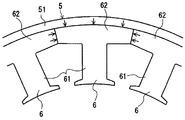
- FIG. 16 shows a state of stress generation in each divided core 6 when a plurality of divided cores 6 are attached in an annular shape on the inner peripheral surface of the cylindrical portion 51 of the retaining ring 5 of the stator.
- Each of the split cores 6 has a tooth portion 61 around which a coil (not shown) is wound, and a back yoke portion 62 connected to the outside of the tooth portion 61 in the radial direction.
- the split cores 6 that are adjacent to each other have a predetermined tightening margin (the outer diameter of the split core 6 minus the outer diameter of the split core 6) in a state where the circumferential ends of the back yoke portion 62 are in contact with each other.
- the inner diameter of the cylindrical portion 51 of the retaining ring 5 is press-fitted.
- each back yoke portion 62 is radially inward from the inner peripheral surface of the cylindrical portion 51 of the retaining ring 5 by press-fitting the retaining core 5 into the cylindrical portion 51 of the split core 6. Is subjected to substantially equal pressing force (surface pressure). Further, both end portions of the back yoke portion 62 receive a circumferential pressing force from the back yoke portion 62 of the adjacent split core 6. Therefore, compressive stress is easily generated in the back yoke portion 62.
- each member of the rotating electrical machine has a variation in dimensions, and the above-described tightening allowance varies due to the variation. If the dimensions of each member are set so that the above-described predetermined tightening allowance is maintained even in the worst case in consideration of dimensional variations, if the tightening allowance increases, the inside of the cylindrical portion 51 of the retaining ring 5 The surface pressure applied from the peripheral surface to the outer peripheral surface of the back yoke portion 62 increases. And when the stress which generate
- each divided core 6 is formed by laminating a large number of thin electromagnetic steel plates, so that buckling of the back yoke portion 62, that is, deformation in which the back yoke portion 62 is bent in the axial direction due to a compressive load occurs.
- the electric machine may be damaged.
- the contact pressure applied from the inner peripheral surface of the cylindrical portion 51 of the retaining ring 5 to the outer peripheral surface of the back yoke portion 62 can be reduced by reducing the thickness of the cylindrical portion 51 of the retaining ring 5.
- the cylindrical portion 51 of the retaining ring 5 breaks when the plurality of split cores 6 are press-fitted or shrink-fitted into the inner peripheral portion of the cylindrical portion 51 of the retaining ring 5. There is a fear.
- the present invention has been made in view of the above circumstances, and its purpose is to reduce the iron loss inside the core due to the surface pressure from the holding ring while maintaining the holding force of the split core by the holding ring, and An object of the present invention is to provide a rotating electrical machine that prevents buckling.
- an invention according to claim 1 includes a rotor that is rotatably attached to a housing, a radially outer side facing the rotor, and a cylindrical portion.
- a holding ring attached to the housing, and a stator plate having a plurality of divided cores, each of which is configured by laminating a core plate made of electromagnetic steel plate, each of which is wound with a coil and fixed to the inner peripheral surface of the cylindrical portion;
- Each of the split cores extends in a radial direction in a state of being attached to the holding ring, and is connected to a tooth portion around which a coil is wound, and radially outward of the tooth portion, A plurality of the split cores in a state where end surfaces of the adjacent back yoke portions are in contact with each other and arranged in an annular shape.
- a rotating electric machine that is fitted to the holding ring by applying a surface pressure to the inner periphery of the cylindrical portion of the ring with a tightening margin by press fitting or shrink fitting, and a slit is formed in the back yoke portion of the split core That is, the back yoke portion is provided so as to penetrate both ends in the circumferential direction.
- the slit is configured such that the distance from the slit to the outer periphery of the back yoke portion is the same as the distance from the inner periphery to the outer periphery of the cylindrical portion of the holding ring. Is formed.
- the slit extends from the slit to the outer periphery of the back yoke portion with respect to the distance from the inner periphery to the outer periphery of the cylindrical portion of the holding ring. That is, the distance ratio is increased.
- the laminated electromagnetic steel sheets are doubly crimped between the slit and the outer periphery of the back yoke portion. It is that you are.
- the divided core is formed by bonding the laminated electromagnetic steel sheets between the slit and the outer periphery of the back yoke portion. It is that you are.
- a rotor that is rotatably attached to a housing, a holding ring that is provided radially opposite to the rotor, has a cylindrical portion, and is attached to the housing;
- a stator plate having a plurality of divided cores, each of which is configured by laminating core plates made of electromagnetic steel plates, each of which is wound with a coil and fixed to the inner peripheral surface of the cylindrical portion.
- a tooth portion that extends in the radial direction and is wound with a coil
- a back yoke portion that is connected radially outward of the teeth portion and extends in the circumferential direction
- the plurality of split cores are press-fitted into the inner periphery of the cylindrical portion of the holding ring in a state where the end surfaces of the adjacent back yoke portions are in contact with each other and arranged in an annular shape.
- a surface pressure is applied to the retaining ring with a tightening margin by fitting, and at least at the center portion in the circumferential direction of the back yoke portion, the back yoke portion has a slit whose longitudinal direction is the circumferential direction. Is formed.
- the invention according to claim 7 is that, in claim 6, the length of the slit in the circumferential direction is equal to or greater than the circumferential length of the teeth portion.
- the slit is formed in an outer peripheral edge portion of the back yoke portion.
- each of the divided cores is formed by laminating a plurality of first core plates and a plurality of second core plates in a predetermined order.
- the first core plate is formed such that an outer periphery of the first core plate protrudes radially outward from an outer periphery of the second core plate, and is formed on the back yoke portion of the first core plate.
- the slits are provided so as to leave both circumferential ends of the back yoke portion.
- the invention according to claim 10 is the invention according to claim 9, wherein the first core plate is formed such that a distance from an outer periphery of the first core plate to an outer periphery of the second core plate is equal to or more than the tightening allowance. It is that you are.
- the plurality of divided cores contact each other in the circumferential direction end surfaces of the back yoke portion of the first core plate that respectively constitute the divided cores adjacent to each other.
- the first core plate and the second core plate are laminated in a predetermined order so that the position and the joining position of the circumferential end faces of the back yoke portion of the second core plate are shifted in the circumferential direction. It is fitted to the holding ring.
- the plurality of divided cores are arranged in the circumferential direction of the back yoke portion of the first core plate that constitutes the divided cores adjacent to each other.
- the first core plate and the second core plate are laminated in a predetermined order so that the end surfaces are in contact with each other and a gap is formed between the circumferential end surfaces of the back yoke portion of the second core plate. It is fitted to the holding ring.
- the slit is formed in the first core plate by press work, and the plurality of first core plates and the plurality of the first core plates stacked.
- the two-core plate is squeezed.
- a notch for positioning at the time of stacking with the second core plate is formed on the outer periphery of the first core plate. It is formed so as to reach the outer periphery of the core plate.
- the divided core in which the plurality of first core plates and the plurality of second core plates are laminated in a predetermined order is provided at both ends. That is, the second core plate is configured by being laminated.
- a rotor that is rotatably attached to a housing, a holding ring that is provided radially opposite to the rotor, has a cylindrical portion, and is attached to the housing.
- a stator plate having a plurality of divided cores, each of which is configured by laminating core plates made of electromagnetic steel plates, each of which is wound with a coil and fixed to the inner peripheral surface of the cylindrical portion.
- a teeth portion that extends in a radial direction and is wound with a coil in a state of being attached to the retaining ring, and a back yoke portion that is connected radially outward of the teeth portion and extends in the circumferential direction.
- the plurality of split cores are press-fitted into the inner periphery of the cylindrical portion of the holding ring in a state where end surfaces of the adjacent back yoke portions are in contact with each other and arranged in an annular shape.
- a surface pressure is applied to the holding ring with a tightening margin by fitting, and each of the divided cores includes a plurality of first core plates and a plurality of second core plates stacked in a predetermined order.
- the first core plate is formed such that an outer periphery of the first core plate protrudes radially outward from an outer periphery of the second core plate, and at least the back of the first core plate is formed.
- a slit having a longitudinal direction in the circumferential direction is formed in the back yoke portion.
- the invention according to claim 17 is the invention according to claim 16, wherein the length of the slit in the circumferential direction is equal to or greater than the circumferential length of the teeth portion of the first core plate.
- the slit is formed in an outer peripheral edge portion of the back yoke portion of the first core plate.
- the slit is provided in the back yoke portion of the split core so as to leave both circumferential ends of the back yoke portion.
- the slit serves as a buffer portion, and the portion between the slit and the outer periphery of the back yoke portion (hereinafter referred to as the bridge portion) receives most of the surface pressure from the cylindrical portion of the retaining ring.
- the stress generated by reducing the surface pressure received by the back yoke portion excluding the portion from the cylindrical portion of the retaining ring can be reduced.
- the slit is a distance from the slit to the outer periphery of the back yoke portion, that is, a radial thickness of the bridge portion, and a distance from the inner periphery to the outer periphery of the cylindrical portion of the holding ring, that is, The cylindrical portion of the retaining ring is formed so as to have the same thickness in the radial direction.
- the radial thickness of the cylindrical portion of the retaining ring can be made thinner than the radial thickness of the conventional cylindrical portion, and as a result Further, the outer diameter of the split core can be widened by reducing the thickness of the cylindrical portion in the radial direction, and a bridge portion can be formed at that portion.
- the outer diameter of the cylindrical part of the retaining ring cannot be increased beyond a certain level.
- the outer diameter of the retaining ring's cylindrical part remains the same as that of the conventional cylindrical part.
- the thickness of the cylindrical portion in the radial direction is, for example, 1 ⁇ 2 of the radial thickness of the conventional cylindrical portion, and the outer diameter of the split core is increased by 1 ⁇ 2 of the radial thickness of the conventional cylindrical portion.
- a bridge portion is formed in the portion so that the rigidity of the cylindrical portion of the holding ring and the rigidity of the bridge portion can be made substantially equal, and the bridge portion can receive most of the surface pressure from the cylindrical portion of the holding ring.
- the size of the rotating electrical machine remains the same as the size of the conventional rotating electrical machine, the area (volume) of the back yoke part other than the bridge part is substantially the same as the conventional one, and the magnetic flux flow can be ensured and maintained as before. Maintaining the holding power of the split core by the ring, improving the efficiency of the rotating electrical machine by reducing the iron loss inside the back yoke part, and preventing the rotating electrical machine from being damaged by preventing buckling of the back yoke part can be achieved.
- the slit increases in the distance from the inner periphery to the outer periphery of the cylindrical portion of the retaining ring, that is, in the radial direction of the cylindrical portion of the retaining ring.
- the distance from the slit to the outer periphery of the back yoke part that is, the ratio of the thickness of the bridge part in the radial direction is increased.
- the laminated electromagnetic steel plates are squeezed between the slit and the outer periphery of the back yoke portion.
- a back yoke part especially a bridge
- the laminated electromagnetic steel sheets are bonded to each other from the slit to the outer periphery of the back yoke portion. This prevents the back yoke part, especially the bridge part from buckling and bending in the axial direction even when the radial thickness of the bridge part is thin and cannot be squeezed. Can be prevented.
- the slit is formed so that the circumferential direction is the longitudinal direction at least in the central portion of the back yoke portion in the circumferential direction.
- the slit serves as a buffer portion and the bridge portion receives most of the surface pressure from the cylindrical portion of the holding ring, so that the back yoke portion excluding the bridge portion receives the surface pressure received from the cylindrical portion of the holding ring. The stress generated by the reduction can be reduced.
- the slit is formed such that its circumferential length is equal to or greater than the circumferential length of the tooth portion.
- the longer the slit is in the circumferential direction the lower the surface pressure that the back yoke part excluding the bridge part receives from the cylindrical part of the retaining ring, thereby reducing the generated stress. Therefore, the iron loss inside the back yoke portion can be further reduced to greatly improve the efficiency of the rotating electrical machine, and buckling of the back yoke portion can be prevented to prevent the rotating electrical machine from being damaged.
- the slit is provided through the outer peripheral edge portion of the back yoke portion of the split core. Accordingly, the surface pressure from the cylindrical portion of the holding ring is received only by the bridge portion provided at the outer peripheral edge portion of the back yoke portion, so that the surface pressure received from the cylindrical portion of the holding ring in the majority of the back yoke portion. It is possible to reduce the generated stress. Therefore, it is possible to achieve both the maintenance of the holding force of the split core by the retaining ring, the improvement of the efficiency of the rotating electrical machine by reducing the iron loss inside the back yoke part, and the prevention of damage to the rotating electrical machine by preventing buckling of the back yoke part. it can.
- each divided core is configured by laminating a plurality of first core plates and a plurality of second core plates in a predetermined order, and the first core plate
- the outer periphery of the first core plate is formed so as to protrude outward in the radial direction from the outer periphery of the second core plate, and slits are provided in the back yoke portion of the first core plate, leaving both end portions in the circumferential direction of the back yoke portion.
- the surface pressure from the cylindrical portion of the holding ring is received only by the back yoke portion of the first core plate protruding from the back yoke portion of the second core plate.
- the slit formed in the first core plate serves as a buffer portion, and a portion between the slit and the outer periphery of the back yoke portion of the first core plate (hereinafter referred to as a bridge portion) is separated from the cylindrical portion of the holding ring. Since the surface pressure is received, the stress generated by reducing the surface pressure received by the back yoke portion excluding the bridge portion from the cylindrical portion of the holding ring can be reduced.
- the first core plate that receives the surface pressure is sandwiched by the second core plate that does not receive the surface pressure and is fixed to the holding ring, the movement of the bridge portion in the axial direction can be suppressed. Even if it is not fixed by dowel crimping or adhesion, it is possible to prevent the bridge portion from buckling and bending in the axial direction. Therefore, it is possible to achieve both the maintenance of the holding force of the split core by the retaining ring, the improvement of the efficiency of the rotating electrical machine by reducing the iron loss inside the back yoke part, and the prevention of damage to the rotating electrical machine by preventing buckling of the back yoke part. it can.
- the first core plate is formed such that the distance from the outer periphery of the first core plate to the outer periphery of the second core plate is equal to or greater than the tightening allowance.
- the plurality of divided cores include the contact positions of the circumferential end surfaces of the back yoke portions of the first core plate that constitute the adjacent divided cores, and the back yoke of the second core plate.
- the first core plate and the second core plate are laminated in a predetermined order and fitted to the holding ring so that the joining positions of the circumferential end faces of the portions are shifted in the circumferential direction.
- the back yoke portion of the first core plate is sandwiched between the back yoke portions of the adjacent second core plates, so that the circumferential end surfaces of the back yoke portions of the first core plate are adjacent to each other.
- the core plate does not come into contact with the circumferential end surface of the back yoke portion, and the circumferential end surfaces of the back yoke portion can be reliably brought into contact with each other.
- the plurality of split cores are in contact with each other in the circumferential end surfaces of the back yoke portions of the first core plate constituting the adjacent split cores, and the back yoke portions of the second core plate.
- the first core plate and the second core plate are laminated in a predetermined order and are fitted to the holding ring so that a gap is generated between the circumferential end faces.
- the surface pressure from the cylindrical portion of the retaining ring hardly propagates between the back yoke portions of the second core plate that constitute the mutually adjacent divided cores, and the inside of the back yoke portion of the second core plate. An increase in iron loss can be prevented.
- the slit is formed in the first core plate by press working, and the plurality of stacked first core plates and the plurality of second core plates are doubly crimped.
- the bridge portion is buckled by a compressive load received from the cylindrical portion of the retaining ring, and is easily bent in the axial direction.
- the first core plate that receives the surface pressure is sandwiched by the second core plate that does not receive the surface pressure and is fixed to the holding ring, the axial movement of the bridge portion is suppressed to prevent buckling.
- the radial width of the slit can be widened so that it can be pressed. Therefore, since the formation of the slits and the formation of the concave and convex portions on the front and back surfaces of the first core plate and the second core plate can be handled only by a series of pressing processes, the manufacturing cost of the split core can be reduced.
- the outer periphery of the first core plate is formed with a positioning notch for stacking with the second core plate so as to reach the outer periphery of the second core plate.
- the plurality of first core plates and the plurality of second core plates are stacked in a mold, and the outer periphery of the first core plate protrudes radially outward from the outer periphery of the second core plate.
- the outer periphery of the first core plate contacts the inner wall of the mold, and the outer periphery of the second core plate does not contact the inner wall of the mold. For this reason, it becomes difficult to laminate the plurality of first core plates and the plurality of second core plates with high accuracy in the mold.
- the positioning notch reaching the outer periphery of the second core plate is formed on the outer periphery of the first core plate, by providing a positioning member that fits into the positioning notch on the inner wall of the mold, The plurality of first core plates and the plurality of second core plates can be stacked with high accuracy in the mold.
- the stacked divided cores are configured by stacking the second core plates on both ends.
- the first core plate is sandwiched on the inner layer side of the second core plate at both ends of the stack, so that the axial movement of the bridge portion of the first core plate can be suppressed, and the bridge portion buckles and axially Can be prevented from being bent.
- each divided core is configured by laminating a plurality of first core plates and a plurality of second core plates in a predetermined order.
- the outer periphery of the one core plate is formed so as to protrude outward in the radial direction from the outer periphery of the second core plate, and at least a slit whose circumferential direction is the longitudinal direction is formed at a central portion in the circumferential direction of the back yoke portion.
- the slit formed in the first core plate serves as a buffer portion, and the bridge portion receives the surface pressure from the cylindrical portion of the holding ring. Therefore, the back yoke portion excluding the bridge portion is separated from the cylindrical portion of the holding ring. It is possible to reduce the stress generated by reducing the contact pressure.
- the first core plate that receives the surface pressure is sandwiched by the second core plate that does not receive the surface pressure and is fixed to the holding ring, the movement of the bridge portion in the axial direction can be suppressed. Even if it is not fixed by dowel crimping or adhesion, it is possible to prevent the bridge portion from buckling and bending in the axial direction. Therefore, it is possible to achieve both the maintenance of the holding force of the split core by the retaining ring, the improvement of the efficiency of the rotating electrical machine by reducing the iron loss inside the back yoke part, and the prevention of damage to the rotating electrical machine by preventing buckling of the back yoke part. it can.
- the slit is formed such that its circumferential length is equal to or greater than the circumferential length of the tooth portion of the first core plate.
- the longer the slit is in the circumferential direction the lower the surface pressure that the back yoke part of the first core plate excluding the bridge part receives from the cylindrical part of the holding ring, and the stress generated can be reduced. Therefore, the iron loss inside the back yoke portion of the first core plate can be further reduced to greatly improve the efficiency of the rotating electrical machine, and the back yoke portion of the first core plate can be prevented from buckling and the rotating electrical machine can be prevented. Can prevent damage.
- the slit is provided through the outer peripheral edge portion of the back yoke portion of the first core plate. Accordingly, the surface pressure from the cylindrical portion of the holding ring is received only by the bridge portion provided at the outer peripheral edge portion of the back yoke portion, so that the surface pressure received from the cylindrical portion of the holding ring in the majority of the back yoke portion. It is possible to reduce the generated stress. Therefore, it is possible to achieve both the maintenance of the holding force of the split core by the retaining ring, the improvement of the efficiency of the rotating electrical machine by reducing the iron loss inside the back yoke part, and the prevention of damage to the rotating electrical machine by preventing buckling of the back yoke part. it can.
- FIG. 3 is a plan view of a single split core included in the stator shown in FIG. 2.
- A is a figure which shows the relationship between the tightening allowance of the cylindrical part and division
- B is the cylindrical part of the holding ring of the conventional rotary electric machine, It is a figure which shows the relationship between the interference with a division
- FIG. 7 shows the minimum principal stress distribution, the magnetic flux density distribution, and the iron loss density distribution generated when the split core of the rotating electrical machine of this embodiment is attached to the holding ring. It is a figure which shows the result analyzed using the method (FEM).
- FEM the method
- FIG. 8 shows the result analyzed using FEM. It is a top view of the stator of the rotary electric machine of 2nd Embodiment.
- FIG. 8 is an exploded perspective view of a single split core included in the stator shown in FIG. 7.
- (A) is a figure which shows the relationship between the tightening allowance of the cylindrical part and division
- (B) is the cylindrical part of the holding ring of the conventional rotary electric machine, It is a figure which shows the relationship between the interference with a division
- (A) Analyzes the minimum principal stress distribution, magnetic flux density distribution, and iron loss density distribution generated when the split core of the rotating electrical machine of this embodiment is attached to the retaining ring, using the finite element method (FEM).
- FEM finite element method
- 5B is a finite element method (FEM) showing the minimum principal stress distribution, magnetic flux density distribution and iron loss density distribution generated when a split core of a conventional rotating electrical machine is attached to a retaining ring. It is a figure which shows the result analyzed using. It is a schematic diagram for demonstrating the mechanism in which a stress generate
- FEM finite element method
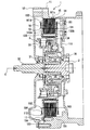
- the rotating electrical machine 1 is a synchronous motor for driving wheels of a hybrid vehicle.
- the left side is sometimes referred to as the front of the rotating electrical machine 1 and the clutch device 3, and the right side is sometimes referred to as the rear, but is not related to the actual direction on the vehicle.
- the direction of the rotation axis or the axial direction means the direction along the rotation axis C of the rotating electrical machine 1, that is, the left-right direction in FIG. 2 and 3, the bobbins 162 and 163 and the coil 164 fitted to the split core 16 are omitted.
- the motor housing 11 (corresponding to the “housing” of the present invention) is sealed with a motor cover 12 at the front in a state in which the rotor 13 and the stator 14 constituting the rotating electrical machine 1 are incorporated. Yes.
- a vehicle engine (not shown) is attached to the front of the motor cover 12, and a transmission (not shown) is disposed behind the motor housing 11.
- a normally closed type clutch device 3 that is a wet multi-plate clutch is interposed between the rotor 13 and the engine.
- the rotating electrical machine 1 is connected to driving wheels of a vehicle (not shown) via a transmission, and the driving force by the rotating electrical machine 1 is input to the driving wheels.
- the engine rotates the drive wheels via the transmission.
- the rotating electrical machine 1 can be operated to assist the engine.
- the rotary electric machine 1 rotates a driving wheel via a transmission.
- the clutch device 3 is released, and the connection between the engine and the rotating electrical machine 1 is released. Further, the rotating electrical machine 1 is driven by the engine via the clutch device 3 and also functions as a generator.
- the input shaft 32 of the clutch device 3 is attached to the inner peripheral end of the motor cover 12 via a bearing 31 so as to be rotatable about the rotation axis C.
- the rotating shaft C is also the rotating shaft of the turbine shaft 2 of the engine, the rotating electrical machine 1 and the transmission.
- the input shaft 32 is connected to the crankshaft of the engine.
- the input shaft 32 is connected to the clutch outer 34 via the engaging portion 33 of the clutch device 3. By engaging / disengaging the engaging portion 33, the input shaft 32 and the clutch outer 34 are intermittently connected.
- the clutch outer 34 is connected to the rotor 13 of the rotating electrical machine 1, extends radially inward, and is splined to the turbine shaft 2 at the inner end.
- a bearing device 35 is interposed between the clutch outer 34 and the fixed wall 111 of the motor housing 11 so as to allow relative rotation between the two.
- the rotor 13 of the rotating electrical machine 1 is rotatably attached to the motor housing 11 via a clutch outer 34.
- the rotor 13 is formed by sandwiching a plurality of laminated electromagnetic steel plates 131 between a pair of holding plates 132a and 132b, and penetrating a fixing member 133 therebetween to caulk the ends.
- a plurality of field pole magnets (not shown) are provided on the circumference of the rotor 13.
- One holding plate 132 b is attached to the clutch outer 34, whereby the rotor 13 is connected to the clutch outer 34.
- the stator 14 of the rotating electrical machine 1 is attached to the inner peripheral surface of the motor housing 11 so as to face the rotor 13 in the radial direction.
- the stator 14 is formed by fitting a plurality of split cores 16 for generating a rotating magnetic field on the inner peripheral surface of the retaining ring 15 with a surface pressure applied by shrink fitting so as to be arranged in an annular shape. (Shown in FIG. 2).
- the holding ring 15 is formed by press-molding a steel plate, and is connected to a ring-shaped cylindrical portion 151 and one end portion of the cylindrical portion 151 in the axial direction, and radially outward over the entire circumference. Further, mounting flanges 153 that extend further outward in the radial direction are formed at three locations on the circumference of the outer peripheral flange 152 (shown in FIG. 2).
- the mounting flange 153 is formed to mount the stator 14 to the motor housing 11, and each has one mounting hole 154 or one mounting hole 154 and one positioning hole 155 passing therethrough (see FIG. 2).
- a portion where the cylindrical portion 151 is connected to the outer peripheral flange 152 and the mounting flange 153 is formed into a curved surface having a predetermined curvature over the entire periphery.
- each divided core 16 includes a tooth portion 161a formed by laminating a plurality of silicon steel plates (electromagnetic steel plates).
- a pair of bobbins 162 and 163 are attached to the teeth portion 161a, and the bobbins 162 and 163 are fitted to each other so as to surround the outer peripheral surface of the teeth portion 161a.
- a coil 164 for generating a rotating magnetic field is wound around the bobbins 162 and 163.
- the coil 164 wound around the tooth portion 161a is connected to an external inverter via a bus ring (not shown).
- a rotating magnetic field is generated in the stator 14 by supplying, for example, a three-phase alternating current to the coil 164, and the rotor 13 is caused by the attractive force or repulsive force caused by the rotating magnetic field. It is rotated relative to the stator 14.
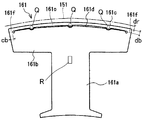
- each divided core 16 has an approximately T-shape.
- the plurality of split cores 16 attached to the holding ring 15 are arranged in an annular shape by abutting the end portions of the back yoke portion 161b with each other to form a core row CR (see FIG. 2).
- each of the split cores 16 is formed with a slit 161d whose longitudinal direction is the circumferential direction at least in the central portion in the circumferential direction of the back yoke portion 161b. That is, at the outer peripheral edge portion located radially inward from the outer peripheral surface 161c of the back yoke portion 161b, it extends in the circumferential direction leaving both circumferential ends of the back yoke portion 161b, and the back yoke portion A slit 161d penetrating 161b in the axial direction is formed (shown in FIGS. 2 and 3).
- Each slit 161d is formed so that the length in the circumferential direction is equal to or greater than the circumferential length of the tooth portion 161a.
- the slit 161d formed in the back yoke portion 161b should not be limited to the shape shown in FIG. 3, and various shapes can be applied as long as they extend in the circumferential direction on the back yoke portion 161b. It is.
- each bridge portion 161e receives most of the surface pressure from the cylindrical portion 151 of the holding ring 15 with each slit 161d serving as a buffer portion. (Shown in FIG. 2).
- the distance from the slit 161d to the outer peripheral surface 161c of the back yoke portion 161b, that is, the radial thickness db of the bridge portion 161e the distance from the inner periphery to the outer periphery of the cylindrical portion 151 of the holding ring 15, that is, the thickness dr of the cylindrical portion 151 of the holding ring 15 is formed to be the same (shown in FIG. 3).
- each slit 161d is formed so that the ratio of the thickness db in the radial direction of the bridge portion 161e to the thickness dr of the cylindrical portion 151 of the holding ring 15 is increased, thereby improving the strength of the bridge portion 161e. Even if the surface pressure from the cylindrical portion 151 of the ring 15 increases, most of the surface pressure can be received, and the stress generated in the back yoke portion 161b excluding the bridge portion 161e can be reduced.
- Each of the slits 161d has a rotational torque applied to the split core 16 when the rotating electrical machine 1 rotates at a portion from the end of the slit 161d to the end of the back yoke portion 161b (hereinafter referred to as the bridge leg portion 161f).
- the vehicle is formed so as not to be broken by an axial force applied to the split core 16 when the vehicle collides with the side. That is, the circumferential length cb of the bridge leg 161f is determined from the above-described rotational torque and axial force (shown in FIG. 3).
- the bridge portion 161e since the bridge portion 161e receives a large part of the surface pressure from the cylindrical portion 151 of the holding ring 15 with the slit 161d serving as a buffer portion, the bridge portion 161e is bent in the axial direction by a compressive load. In order to prevent buckling, it is squeezed at three points Q (shown in FIG. 3). In addition, since the generated stress is reduced in the portion of the split core 16 other than the bridge portion 161e, it may be squeezed at one point R in the substantially central portion of the split core 16 (shown in FIG. 3). Moreover, when the thickness of the bridge part 161e is thin and it cannot do a caulking, it is good to adhere
- the plurality of divided cores 16 are attached to the inner peripheral surface of the cylindrical portion 151 by shrink fitting.
- the retaining ring 15 is heated to a predetermined temperature, and its inner diameter is expanded.
- the plurality of cores 16 are inserted in an annular shape by bringing the back yokes 161b of the cores 16 into contact with the heated cylindrical part 151. After the split cores 16 are inserted into the cylindrical portion 151, the holding ring 15 is cooled and contracted, and each split core 16 can be firmly held.
- the split core 16 is held in the holding ring 15 by press-fitting. Furthermore, when the split core 16 is held in the holding ring 15 by press-fitting, an adhesive may be interposed between the split core 16 and the cylindrical portion 151 to increase the holding force.
- the holding ring 15 to which the split core 16 is attached is fixed to the motor housing 11. After the mounting flange 153 is brought into contact with the boss 112 of the motor housing 11, the mounting bolt 17 is inserted into the mounting hole 154 and screwed into the boss 112, so that the mounting flange 153 is attached to the motor housing 11.
- FIG. 4A is a view showing the relationship between the fastening allowance V and the surface pressure P between the cylindrical portion 151 and the split core 16 of the holding ring 15 of the present embodiment
- FIG. 4B is a conventional holding ring 5. It is a figure which shows the relationship between the interference V and the surface pressure P of the cylindrical part 51 of this, and the division
- FIG. 5A, 5 ⁇ / b> B, and 5 ⁇ / b> C show the minimum principal stress distribution, magnetic flux density distribution, and iron loss density distribution generated when the split core 16 of this embodiment is attached to the retaining ring 15. It is a figure which shows the result analyzed using the element method (FEM).
- FEM element method
- 6A, 6B, and 6C show the minimum principal stress distribution, the magnetic flux density distribution, and the iron loss density distribution generated when the conventional split core 6 is attached to the retaining ring 5, and the finite element method is used. It is a figure which shows the result analyzed using (FEM). 5 and 6, the smaller the number assigned to the region, the higher the minimum principal stress, the magnetic flux density and the iron loss density, and the larger the number attached to the region, the minimum principal stress, the magnetic flux density and the iron. Loss density is low.
- the surface pressures P1 and P1 can hold the split cores 6 and 161 in the circumferential direction and the axial direction with respect to the cylindrical portions 51 and 151 of the holding rings 5 and 15, that is, the holding ring.
- the divided cores 6 and 161 do not rotate in the circumferential direction with respect to the 5 and 15 cylindrical portions 51 and 151, and represent the minimum surface pressure that does not come off in the axial direction.
- the surface pressures P2 and P3 represent the tensile limit of the cylindrical portions 51 and 151 of the retaining rings 5 and 15, that is, the maximum surface pressure at which the cylindrical portions 51 and 151 of the retaining rings 5 and 15 break.
- the axial cross-sectional area of the cylindrical portion 151 of the retaining ring 15 is approximately half of the axial sectional area of the cylindrical portion 51 of the conventional retaining ring 5, so the surface pressure P ⁇ b> 2 is the surface pressure. About half of P3.
- the bridge part 161e bends by the surface pressure P from the cylindrical part 151 of the holding ring 15, it is applied to the cylindrical part 151 of the holding ring 15 of this embodiment by the fastening margin V.
- the load is smaller than the load applied to the cylindrical portion 51 of the conventional holding ring 5 due to the same fastening allowance V.
- the tightening margin V even if the tightening margin V is increased, the increase in the surface pressure P can be suppressed. That is, in the past, the maximum contact pressure P31 ( ⁇ P3), for example, 5.2 MPa was reached when the tightening margin was set to V4, but in this embodiment, the tightening margin is 1.5 times larger than the tightening margin V4. When V2 is reached, the maximum surface pressure P21 ( ⁇ P2), which is half of the surface pressure P31, for example, 2.6 MPa is reached.
- the tightening allowance establishment range V1 to V2 of this embodiment for example, 0.074 mm to 0.48 mm ( ⁇ 0.406 mm) is used as the conventional allowance allowance establishment range V3 to V4, for example, 0.024 mm to 0.298 mm ( ( ⁇ 0.274 mm). Therefore, since the allowable range (processing tolerance) of the dimensional variation of each member of the rotating electrical machine 1 is wider than the conventional one, the surface pressure between the cylindrical portion 151 of the holding ring 15 and the split core 16 increases excessively. This can be suppressed.
- the stress generated in the back yoke portion 62 of the conventional split core 6 is as follows. Although the stress was excessive, for example, a compressive stress of 33.4 MPa (shown in FIG. 6A), the stress generated in the back yoke portion 161b of the split core 16 of the present embodiment is the bridge portion 161e (the length of the dotted line). Only the portion surrounded by the circle a) becomes an excessive stress, for example, a compressive stress of 33.4 MPa, and the stress of the other portions, particularly both ends of the back yoke portion 161b (portion surrounded by the dotted ellipse b) is reduced.
- a compressive stress of 33.4 MPa shown in FIG. 6A
- a compressive stress of 3.8 MPa (shown in FIG. 5A).
- the magnetic flux density (shown in FIG. 5B) at both ends of the back yoke portion 161b of the split core 16 of the present embodiment (portion surrounded by a dotted oval) is the back yoke portion 62 of the conventional split core 6.
- the magnetic flux density at both ends (portion surrounded by a dotted-line ellipse) is lower than that shown in FIG.
- the iron loss density (shown in FIG. 5C) at both ends of the back yoke portion 161b of the split core 16 of the present embodiment (portion surrounded by a dotted-line ellipse) is the back yoke portion of the conventional split core 6. It is more relaxed than the iron loss density (shown in FIG. 6C) at both ends of 62 (portion surrounded by a dotted oval).
- the slit 161d is provided in the back yoke portion 161b of the split core 16 so as to leave both circumferential ends of the back yoke portion 161b.
- the slit 161 d serves as a buffer portion, and the bridge portion 161 e receives most of the surface pressure from the cylindrical portion 151 of the holding ring 15, so that the back yoke portion 161 b excluding the bridge portion 161 e serves as the holding ring 15.
- the stress generated by reducing the surface pressure received from the cylindrical portion 151 can be reduced.
- the slit 161d is formed so that the radial thickness of the bridge portion 161e and the radial thickness of the cylindrical portion 151 of the holding ring 15 are the same. ing.
- the bridge portion 161e receives most of the surface pressure from the cylindrical portion 151 of the retaining ring 15. Therefore, the stress generated in the back yoke portion 161b excluding the bridge portion 161e can be reduced, for example, half of the stress generated conventionally.
- the radial thickness of the cylindrical portion 151 of the holding ring 15 is made thinner than the radial thickness of the conventional cylindrical portion 51.
- the outer diameter of the split core 16 can be widened by reducing the thickness of the cylindrical portion 151 in the radial direction, and the bridge portion 161e can be formed at that portion.
- the outer diameter of the cylindrical portion 151 of the retaining ring 15 cannot be increased beyond a certain level, but the outer diameter of the cylindrical portion 151 of the retaining ring 15 is the outer diameter of the conventional cylindrical portion 51.
- the radial thickness of the cylindrical portion 151 of the retaining ring 15 is, for example, 1 ⁇ 2 of the radial thickness of the conventional cylindrical portion 51, and the outer diameter of the split core 16 is set to the radius of the conventional cylindrical portion 51.
- the bridge portion 161e is formed by expanding the thickness by 1 ⁇ 2 of the thickness in the direction, and the rigidity of the cylindrical portion 151 of the holding ring 15 and the rigidity of the bridge portion 161e can be made substantially equal, and are held by the bridge portion 161e. Most of the surface pressure from the cylindrical portion 151 of the ring 15 can be received. Therefore, the size of the rotating electrical machine 1 remains the same as the size of the conventional rotating electrical machine, and the area (volume) of the back yoke portion 161b other than the bridge portion 161e is substantially the same as the conventional one to ensure the flow of magnetic flux as in the conventional case.
- the retaining ring 15 maintains the holding force of the split core 16, improves the efficiency of the rotating electrical machine 1 by reducing the iron loss inside the back yoke part 161b, and prevents the rotating electrical machine 1 from being damaged by preventing buckling of the back yoke part 161b. Can be made compatible.
- the slit 161d is a bridge portion with respect to the radial thickness of the cylindrical portion 151 of the retaining ring 15 as the surface pressure from the cylindrical portion 151 of the retaining ring 15 increases.
- 161e is formed so that the ratio of the thickness in the radial direction is increased.
- the strength of the bridge portion 161e is improved, so that even if the surface pressure from the cylindrical portion 151 of the retaining ring 15 is increased, most of the surface pressure can be received, and the back yoke portion 161b excluding the bridge portion 161e. It is possible to reduce the stress generated in.
- the divided cores 16 are stiffened between the laminated electromagnetic steel plates from the slit 161d to the outer peripheral surface 161c of the back yoke portion 161b.
- the back yoke portion 161b, in particular, the bridge portion 161e from buckling and bending in the axial direction, and to prevent the rotating electrical machine 1 from being damaged.
- stacked electromagnetic steel plates are adhere
- the back yoke portion 161b particularly the bridge portion 161e, can be prevented from buckling and bending in the axial direction. Damage to the electric machine 1 can be prevented.
- the slit 161d is formed so that the circumferential direction is the longitudinal direction at least in the circumferential central portion of the back yoke portion 161b.
- the slit 161 d serves as a buffer portion, and the bridge portion 161 e receives most of the surface pressure from the cylindrical portion 151 of the holding ring 15, so that the back yoke portion 161 b excluding the bridge portion 161 e serves as the holding ring 15.
- the stress generated by reducing the surface pressure received from the cylindrical portion 151 can be reduced.
- the slit 161d is formed such that its circumferential length is equal to or greater than the circumferential length of the tooth portion 161a.
- the longer the slit 161d is in the circumferential direction the lower the surface pressure that the back yoke portion 161b excluding the bridge portion 161e receives from the cylindrical portion 151 of the holding ring 15 can be reduced. Therefore, the iron loss inside the back yoke portion 161b can be further reduced to significantly improve the efficiency of the rotating electrical machine 1, and the buck yoke of the back yoke portion 161b can be prevented to prevent the rotating electrical machine 1 from being damaged. Can do.
- the slit 161d is provided through the edge of the outer peripheral surface 161c of the back yoke portion 161b of the split core 16.
- the surface pressure from the cylindrical portion 151 of the holding ring 15 is received only by the bridge portion 161e provided at the edge of the outer peripheral surface 161c of the back yoke portion 161b, so that the holding ring is mostly in the back yoke portion 161b.
- the stress generated by reducing the surface pressure received from the 15 cylindrical portions 151 can be reduced.
- the rotating electrical machine of the second embodiment has basically the same configuration as the rotating electrical machine 1 of the first embodiment shown in FIG.
- the same components as those of the rotating electrical machine 1 according to the first embodiment are denoted by the same reference numerals, and detailed description thereof is omitted.
- each split core 16 extends in the radial direction when attached to the holding ring 15, and is connected to the teeth portion 161 a around which the coil 164 is wound, and radially outward of the teeth portion 161 a. And a back yoke portion 161b extending in the circumferential direction (shown in FIG. 7).
- each divided core 16 has an approximately T-shape.
- the plurality of divided cores 16 attached to the holding ring 15 are arranged in an annular shape by abutting the end portions of the back yoke portion 161b with each other to form a core row CR.
- a pair of bobbins 162 and 163 are attached to the teeth portion 161a, and the bobbins 162 and 163 are fitted to each other so as to surround the outer peripheral surface of the teeth portion 161a. Further, a coil 164 for generating a rotating magnetic field is wound around the bobbins 162 and 163. The coil 164 wound around the tooth portion 161a is connected to an external inverter via a bus ring (not shown).
- a rotating magnetic field is generated in the stator 14 by supplying, for example, a three-phase alternating current to the coil 164, and the rotor 13 is caused by the attractive force or repulsive force caused by the rotating magnetic field. It is rotated relative to the stator 14.
- each of the divided cores 16 includes a first core plate 165 and a second core plate 166 made of silicon steel plates having two types of shapes, in a predetermined order, for example, one by one alternately, or an arbitrary number of sheets. It is formed by laminating a plurality of sheets alternately.
- the first core plate 165 is formed with a slit 165d whose longitudinal direction is the circumferential direction at least in the central portion in the circumferential direction of the first back yoke portion 165b.
- the first core plate 165 has an outer peripheral edge portion located radially inward by a predetermined distance from the outer periphery 165c of the portion constituting the back yoke portion 161b of the split core 16 (hereinafter referred to as the first back yoke portion 165b).
- a slit 165d that extends in the circumferential direction leaving both circumferential ends of the first back yoke portion 165b and penetrates the first back yoke portion 165b in the axial direction is formed.
- Each slit 165d is formed so that the length in the circumferential direction is equal to or greater than the circumferential length of the first tooth portion 165a of the first core plate 165.
- a portion corresponding to the slit 165d is not formed in a portion (hereinafter referred to as a second back yoke portion 166b) constituting the back yoke portion 161b of the split core 16 in the second core plate 166.
- each bridge portion 165e receives a surface pressure from the cylindrical portion 151 of the holding ring 15 with each slit 165d serving as a buffer portion ( Fig. 7). Therefore, when the same number of first core plates 165 and second core plates 166 are stacked, in order to halve the stress generated in the first back yoke portion 165b excluding the bridge portion 165e, for example, the first back from the slit 165d.
- the distance to the outer periphery 165c of the yoke portion 165b, that is, the radial thickness db of the bridge portion 165e is the distance from the inner periphery to the outer periphery of the cylindrical portion 151 of the retaining ring 15, that is, the thickness of the cylindrical portion 151 of the retaining ring 15. It is formed to be twice the dr.
- the slits 165d are formed so that the ratio of the thickness db in the radial direction of the bridge portion 165e to the thickness dr of the cylindrical portion 151 of the holding ring 15 is increased, thereby improving the strength of the bridge portion 165e. Even if the surface pressure from the cylindrical portion 151 of the ring 15 increases, the surface pressure can be received, and the stress generated in the first back yoke portion 165b excluding the bridge portion 165e can be reduced.
- each slit 165d is a portion of the slit 165d from the end portion of the first back yoke portion 165b (hereinafter referred to as a bridge leg portion 165f) that rotates on the split core 16 when the rotating electrical machine 1 rotates. It is formed so as not to be broken by torque or an axial force applied to the split core 16 when the vehicle collides with the side, for example. That is, the circumferential length cb of the bridge leg 165f is determined from the above-described rotational torque and axial force.
- the first core plate 165 has an outer periphery 165 c of the first back yoke portion 165 b of the first core plate 165, and the second back yoke portion 166 b of the second core plate 166.
- the outer periphery 166c is formed so as to protrude outward in the radial direction.
- the protruding length that is, the distance sb from the outer periphery 165c of the first back yoke portion 165b to the outer periphery 166c of the second back yoke portion 166b is formed to be equal to or greater than the tightening allowance with the cylindrical portion 151 of the holding ring 15. Yes.
- the plurality of split cores 16 are radially outward from the outer periphery 165c of the first back yoke portion 165b by a distance sb greater than the outer periphery 166c than the outer periphery 166c of the second back yoke portion 166b.
- the outer periphery 166c of the second back yoke portion 166b does not contact the inner peripheral surface of the cylindrical portion 151 of the holding ring 15, so that the first Only the outer periphery 165c of the back yoke portion 165b contacts.
- a portion constituting the tooth portion 161 a of the split core 16 in the first core plate 165 (hereinafter referred to as the first tooth portion 165 a) is split in the second core plate 166.
- the first back yoke portion 165b of the first core plate 165 is formed in the same shape as a portion constituting the tooth portion 161a of the core 16 (hereinafter referred to as the second tooth portion 166a).
- the lengths ub1 and ub2 of the outer peripheries 165c and 166c are substantially the same as the second back yoke portion 166b, and are formed to be shifted by a predetermined length vb in the circumferential direction.
- the plurality of divided cores 16 are in contact with the contact positions r1 between the circumferential end surfaces of the first back yoke portion 165b of the first core plate 165 constituting the divided cores 16 adjacent to each other.
- the first core plate 165 and the second core plate 166 are alternately stacked in a state where the joining position r2 between the circumferential end faces of the second back yoke portion 166b of the second core plate 166 is shifted in the circumferential direction. And is fitted to the cylindrical portion 151 of the holding ring 15.
- circumferential direction end surfaces of the adjacent 1st back yoke part 165b contact
- the circumferential direction end surfaces of the adjacent second back yoke portions 166b may be lightly joined, they may be joined with a minute gap.
- the second core plate 166 has a length ub2 of the outer periphery 166c of the second back yoke portion 166b of the second core plate 166, and a length ub1 of the outer periphery 165c of the first back yoke portion 165b of the first core plate 165. You may form so that it may become slightly shorter than. As a result, as shown in FIG. 12, the plurality of split cores 16 are in contact with each other in the circumferential direction end surfaces of the first back yoke portions 165b of the first core plates 165 constituting the split cores 16 adjacent to each other. The first core plate 165 and the second core plate 166 are alternately stacked in a state where a gap x is generated between the circumferential end faces of the second back yoke portion 166b of the core plate 166.
- each of the divided cores 16 includes a first core plate 165 and a second core plate 166 formed by punching electromagnetic steel sheets by press working, positioned in a mold 167, and sequentially stacked. It is formed by joining.
- the bridge portion 165e receives the surface pressure from the cylindrical portion 151 of the retaining ring 15 with the slit 165d serving as a buffer portion.
- the bridge portion 165e of the first core plate 165 is sandwiched between the second core plates 166, so that the occurrence of buckling in which the bridge portion 165e is bent in the axial direction due to a compressive load is prevented. Is done.
- the split core 16 when the split core 16 is formed in the mold 167, at least the lowermost layer and the uppermost core plate are the second core plates 166 that do not have the slits 165d, so that the bridge portion 165e that is easily buckled is formed. Since the first core plate 165 formed by the slits 165d is not disposed at both ends of the split core 16 where buckling is likely to occur, buckling of the bridge portion 165e can be prevented. For the above-described reason, it is not necessary to reinforce the bridge portion 165e and strengthen the strength.
- the two points Q in the circumferential direction inward in the radial direction and the point R at substantially the center of the first and second tooth portions 165a and 166a are connected by dowel caulking.
- the first core plate 165 has an outer periphery 165c of the first back yoke portion 165b protruding radially outward from the outer periphery 166c of the second back yoke portion 166b by a distance sb.
- two (or three) notches 165f for positioning when stacked with the second core plate 166 are provided on the outer periphery 165c of the first back yoke portion 165b of the first core plate 165.
- the two-core plate 166 is formed so as to reach the outer periphery 166c of the second back yoke portion 166b.
- first projecting portions as positioning members that enter the notch 165f into the die 167 and abut against the outer peripheries 165c, 166c of the first and second back yoke portions 165b, 166b.
- 167a and two second protrusions 167b are provided as positioning members that contact and position on both sides in the circumferential direction of the first and second teeth 165a, 166a.
- the first core plate 165 in the die 167 is also formed in the outer periphery 166c of the second back yoke portion 166b of the second core plate 166 by forming a minute notch at a position corresponding to the notch 165f.
- the positioning accuracy of the second core plate 166 with respect to can be further improved.
- the plurality of divided cores 16 are attached to the inner peripheral surface of the cylindrical portion 151 by shrink fitting.
- the retaining ring 15 is heated to a predetermined temperature, and its inner diameter is expanded.
- the plurality of cores 16 are inserted in an annular shape by bringing the back yokes 161b of the cores 16 into contact with the heated cylindrical part 151. After the split cores 16 are inserted into the cylindrical portion 151, the holding ring 15 is cooled and contracted, and each split core 16 can be firmly held.
- the split core 16 is held in the holding ring 15 by press-fitting. Furthermore, when the split core 16 is held in the holding ring 15 by press-fitting, an adhesive may be interposed between the split core 16 and the cylindrical portion 151 to increase the holding force.
- the holding ring 15 to which the split core 16 is attached is fixed to the motor housing 11. After the mounting flange 153 is brought into contact with the boss 112 of the motor housing 11, the mounting bolt 17 is inserted into the mounting hole 154 and screwed into the boss 112, so that the mounting flange 153 is attached to the motor housing 11.
- FIG. 14A is a diagram showing the relationship between the fastening allowance V and the surface pressure P between the cylindrical portion 151 and the split core 16 of the holding ring 15 of the present embodiment
- FIG. 14B is the conventional holding ring 5. It is a figure which shows the relationship between the interference V and the surface pressure P of the cylindrical part 51 of this, and the division
- FIG. FIG. 15A is a diagram illustrating a result of analyzing the minimum principal stress distribution generated when the split core 16 of the present embodiment is attached to the retaining ring 15 using a finite element method (FEM). The left half shows the minimum principal stress distribution of the first core plate 165, and the right half shows the minimum principal stress distribution of the second core plate 166.
- FEM finite element method
- 15B is a diagram showing a result of analyzing the minimum principal stress distribution generated when the conventional split core 6 is attached to the retaining ring 5 by using the finite element method (FEM).
- FEM finite element method
- the surface pressures P1 and P1 can hold the split cores 6 and 161 in the circumferential direction and the axial direction with respect to the cylindrical portions 51 and 151 of the holding rings 5 and 15, that is, the holding ring 5.
- 15 represents the minimum surface pressure at which the split cores 6 and 161 do not rotate in the circumferential direction and do not come off in the axial direction with respect to the cylindrical portions 51 and 151.
- the surface pressures P2 and P3 represent the tensile limit of the cylindrical portions 51 and 151 of the retaining rings 5 and 15, that is, the maximum surface pressure at which the cylindrical portions 51 and 151 of the retaining rings 5 and 15 break.
- the axial cross-sectional area of the cylindrical portion 151 of the retaining ring 15 is approximately half of the axial sectional area of the cylindrical portion 51 of the conventional retaining ring 5, so the surface pressure P ⁇ b> 2 is the surface pressure. About half of P3.
- the bridge part 161e bends by the surface pressure P from the cylindrical part 151 of the holding ring 15, it is applied to the cylindrical part 151 of the holding ring 15 of this embodiment by the fastening margin V.
- the load is smaller than the load applied to the cylindrical portion 51 of the conventional holding ring 5 due to the same fastening allowance V.
- the fastening allowance establishment range V1 to V2 of the present embodiment can be expanded from the conventional fastening allowance establishment range V3 to V4.
- the allowable range (processing tolerance) of the dimensional variation of each member of the rotating electrical machine 1 is wider than the conventional one, the surface pressure between the cylindrical portion 151 of the holding ring 15 and the split core 16 increases excessively. This can be suppressed.
- the stress generated in the back yoke portion 62 of the conventional split core 6 is excessive stress (compressive stress) (FIG. 15B).
- the stress generated in the back yoke portion 161b of the split core 16 of this embodiment is an excessive stress (compressive stress) in the bridge portion 165e of the first core plate 165 (portion surrounded by the dotted oval a).
- the other portions in particular, the center portion of the first back yoke portion 165b of the first core plate 165 (the portion surrounded by the dotted ellipse b) and the second teeth portion 166a and the second back yoke of the second core plate 166
- the stress of the portion 166b becomes extremely reduced stress (compressive stress) (shown in FIG. 15A). Therefore, the iron loss of the back yoke part 161b of the split core 16 of this embodiment is reduced more than the iron loss of the back yoke part 62 of the conventional split core 6.
- each divided core 16 includes a plurality of first core plates 165 and a plurality of second core plates 166 stacked in a predetermined order.
- the first core plate 165 is formed such that the outer periphery 165c of the first core plate 165 protrudes radially outward from the outer periphery 166c of the second core plate 166.
- a slit 165d is provided in one back yoke portion 165b so as to penetrate both ends in the circumferential direction of the first back yoke portion 165b.
- the surface pressure from the cylindrical portion 151 of the holding ring 15 is received only by the first back yoke portion 165b of the first core plate 165 protruding from the second back yoke portion 166b of the second core plate 166.
- the slit 165d formed in the first core plate 165 serves as a buffer portion, and the bridge portion 165e receives the surface pressure from the cylindrical portion 151 of the holding ring 15. Therefore, the first back yoke excluding the bridge portion 165e is used.
- the stress generated by reducing the surface pressure that the portion 165b receives from the cylindrical portion 151 of the retaining ring 15 can be reduced.
- the first core plate 165 that receives the surface pressure is sandwiched by the second core plate 166 that does not receive the surface pressure and is fixed to the holding ring 15, the axial movement of the bridge portion 165e can be suppressed. Even if the bridge portions 165e are not fixed to each other by doweling or bonding, the bridge portion 165e can be prevented from buckling and bending in the axial direction. Therefore, maintaining the holding force of the split core 16 by the retaining ring 15, improving the efficiency of the rotating electrical machine 1 by reducing the iron loss inside the back yoke part 161b, and preventing damage to the rotating electrical machine 1 by preventing buckling of the back yoke part 161b. Can be made compatible.
- the slit 165d has a radial thickness of the bridge portion 165e that is twice the radial thickness of the cylindrical portion 151 of the holding ring 15. Is formed.
- the bridge portion 165e receives a surface pressure from the cylindrical portion 151 of the retaining ring 15.
- the thickness of the bridge portion 165e in the radial direction is increased.
- the stress generated in the first back yoke portion 165b excluding the bridge portion 165e is reduced, for example, half of the stress generated conventionally. Can be.
- the radial thickness of the cylindrical portion 151 of the holding ring 15 is made thinner than the radial thickness of the conventional cylindrical portion 51.
- the outer diameter of the split core 16 can be widened by reducing the thickness of the cylindrical portion 151 in the radial direction, and the bridge portion 165e can be formed at that portion.
- the outer diameter of the cylindrical portion 151 of the retaining ring 15 cannot be increased beyond a certain level, but the outer diameter of the cylindrical portion 151 of the retaining ring 15 is the outer diameter of the conventional cylindrical portion 51.
- the radial thickness of the cylindrical portion 151 of the retaining ring 15 is, for example, 1 ⁇ 2 of the radial thickness of the conventional cylindrical portion 51, and the outer diameter of the split core 16 is set to the radius of the conventional cylindrical portion 51.
- the bridge portion 165e having a thickness twice as large as the radial thickness of the conventional cylindrical portion 51 is formed, and the rigidity of the cylindrical portion 151 of the retaining ring 15 and the bridge portion 165e are increased.
- the rigidity can be made substantially equal, and the bridge portion 165e can receive the surface pressure from the cylindrical portion 151 of the holding ring 15. Since the first core plate 165 having the bridge portion 165e is sandwiched between the second core plates 166 without the bridge portion 165e, the thickness of the bridge portion 165e is twice the radial thickness of the conventional cylindrical portion 51. Thus, even if the iron loss of the bridge portion 165e becomes large, there is no particular problem without affecting the overall iron loss. Therefore, the size of the rotating electrical machine 1 remains the same as the size of the conventional rotating electrical machine, the area (volume) of the first back yoke portion 165b other than the bridge portion 165e is substantially the same as the conventional one, and the flow of magnetic flux is the same as the conventional one.
- the slit 165d has a bridge portion with respect to the radial thickness of the cylindrical portion 151 of the holding ring 15 as the surface pressure from the cylindrical portion 151 of the holding ring 15 increases. It is formed so that the ratio of the thickness of 165e in the radial direction is increased. As a result, the strength of the bridge portion 165e is improved, so even if the surface pressure from the cylindrical portion 151 of the retaining ring 15 increases, the surface pressure can be received, and the first back yoke portion 165b excluding the bridge portion 165e The generated stress can be reduced.
- the distance sb from the outer periphery 165c of the first core plate 165 to the outer periphery 166c of the second core plate 166 is equal to or greater than the tightening margin. It is formed as follows. As a result, the surface pressure from the cylindrical portion 151 of the holding ring 15 is not always applied to the second back yoke portion 166b of the second core plate 166, and is received only by the first back yoke portion 165b of the first core plate 165. Therefore, the stress generated in the second back yoke part 166b of the second core plate 166 can be reliably reduced, and the iron loss inside the second back yoke part 166b of the second core plate 166 can be reduced.
- the plurality of divided cores 16 are arranged between the circumferential end faces of the first back yoke portion 165b of the first core plate 165 that constitutes the divided cores 16 adjacent to each other.
- the first core plate 165 and the second core plate 166 are predetermined so that the contact position r1 and the joining position r2 between the circumferential end surfaces of the second back yoke portion 166b of the second core plate 166 are shifted in the circumferential direction.
- the layers are laminated in order and fitted to the holding ring 15.
- the first back yoke portion 165b of the first core plate 165 is sandwiched between the first back yoke portions 166b of the adjacent second core plate 166. Therefore, the first back yoke of the first core plate 165 The circumferential end surface of the portion 165b does not hit against the circumferential end surface of the second back yoke portion 166b of the adjacent second core plate 166, and the circumferential end surfaces of the second back yoke portion 166b are reliably in contact with each other. can do.
- the plurality of divided cores 16 have the circumferential end surfaces of the first back yoke portion 165b of the first core plate 165 constituting the divided cores 16 adjacent to each other.
- the first core plate 165 and the second core plate 166 are configured and held in a predetermined order so that a space is generated between the circumferential end surfaces of the second back yoke portion 166b of the second core plate 166 in contact with each other. It is fitted to the ring 15.
- the surface pressure from the cylindrical portion 151 of the retaining ring 15 hardly propagates between the second back yoke portions 166b of the second core plates 166 constituting the adjacent divided cores 16, respectively.
- An increase in iron loss inside the second back yoke portion 166b of the plate 166 can be prevented.
- the slits 165d are formed in the first core plate 165 by press working, and the plurality of stacked first core plates 165 and the plurality of second core plates 166 are doweled.
- the width of the slit 165d in the radial direction is widened so as to be press-workable, the bridge portion 165e is easily buckled by the compressive load received from the cylindrical portion 151 of the holding ring 15, and is easily bent in the axial direction.
- the first core plate 165 that receives the surface pressure is sandwiched by the second core plate 166 that does not receive the surface pressure and is fixed to the holding ring 15, the axial movement of the bridge portion 165e is suppressed to buckle.
- the width of the slit 165d in the radial direction can be widened so that it can be pressed. Therefore, since the formation of the slits 165d and the formation of the concave and convex portions for the dowel crimping on the front and back surfaces of the first core plate 165 and the second core plate 166 can be dealt with only by a series of pressing processes, the manufacturing cost of the split core 16 can be reduced Can do.
- the notch 165f for positioning when the second core plate 166 is stacked is provided on the outer periphery 165c of the first core plate 165. It is formed so as to reach the outer periphery 166c.
- the plurality of first core plates 165 and the plurality of second core plates 166 are stacked in a mold 167, and the outer periphery 165c of the first core plate 165 is more than the outer periphery 166c of the second core plate 166.
- the first protruding portion serves as a positioning member that fits into the positioning notch 165f.
- the laminated cores 16 are configured by laminating the second core plates 166 at both ends. Thereby, since the first core plate 165 is sandwiched between the second core plates 166 at both ends of the stack, the axial movement of the bridge portion 165e of the first core plate 165 can be suppressed, and the bridge portion 165e It can prevent buckling and bending in the axial direction.
- each divided core 16 is configured by laminating a plurality of first core plates 165 and a plurality of second core plates 166 in a predetermined order
- the first core plate 165 is formed such that the outer periphery 165c of the first core plate 165 protrudes radially outward from the outer periphery 166c of the second core plate 166, and at least the circumferential direction of the first back yoke portion 165b.
- a slit 165d whose longitudinal direction is the circumferential direction is formed in the central portion.
- the surface pressure from the cylindrical portion 151 of the holding ring 15 is received only by the first back yoke portion 165b of the first core plate 165 protruding from the second back yoke portion 166b of the second core plate 166.
- the slit 165d formed in the first core plate 165 serves as a buffer portion, and the bridge portion 165e receives the surface pressure from the cylindrical portion 151 of the holding ring 15. Therefore, the first back yoke excluding the bridge portion 165e is used.
- the stress generated by reducing the surface pressure that the portion 165b receives from the cylindrical portion 151 of the retaining ring 15 can be reduced.
- the first core plate 165 that receives the surface pressure is sandwiched by the second core plate 166 that does not receive the surface pressure and is fixed to the holding ring 15, the axial movement of the bridge portion 165e can be suppressed. Even if the bridge portions 165e are not fixed to each other by doweling or bonding, the bridge portion 165e can be prevented from buckling and bending in the axial direction. Therefore, maintaining the holding force of the split core 16 by the retaining ring 15, improving the efficiency of the rotating electrical machine 1 by reducing the iron loss inside the back yoke part 161b, and preventing damage to the rotating electrical machine by preventing buckling of the back yoke part 161b. Can be made compatible.
- the slit 165d has a circumferential length equal to or greater than the circumferential length of the first teeth portion 165a of the first core plate 165. Is formed.
- the longer the slit 165d is in the circumferential direction the lower the surface pressure that the first back yoke part 165b excluding the bridge part 165e receives from the cylindrical part 151 of the holding ring 15 can be reduced. Therefore, the iron loss inside the first back yoke part 165b can be further reduced to greatly improve the efficiency of the rotating electrical machine 1, and the buckling of the first back yoke part 165b can be prevented to damage the rotating electrical machine 1. Can be prevented.
- the slit 165d is provided through the outer peripheral edge portion of the first back yoke portion 165b of the first core plate 165.
- the surface pressure from the cylindrical portion 151 of the retaining ring 15 is received only by the bridge portion 165e provided at the outer peripheral edge portion of the first back yoke portion 165b, and therefore, in most of the first back yoke portion 165b.
- the stress generated by reducing the surface pressure received from the cylindrical portion 151 of the retaining ring 15 can be reduced.
- the rotating electric machine is maintained by maintaining the holding force of the split core 16 by the holding ring 15, improving the efficiency of the rotating electric machine 1 by reducing the iron loss inside the first back yoke part 165b, and preventing the buckling of the first back yoke part 165b. 1 damage prevention can be made compatible.
- the present invention is not limited to the above-described embodiments, and can be modified or expanded as follows.
- the present invention can be applied not only to a split core formed by laminating a plurality of electromagnetic steel plates, but also to a split core formed by pressure forming metal magnetic powder.
- the rotating electrical machine 1 can be applied to a motor provided in household electric appliances such as a synchronous motor, an induction motor, a DC motor, or a motor that drives a general industrial machine.
Landscapes
- Engineering & Computer Science (AREA)
- Power Engineering (AREA)
- Iron Core Of Rotating Electric Machines (AREA)
Priority Applications (3)
| Application Number | Priority Date | Filing Date | Title |
|---|---|---|---|
| EP11789606.8A EP2579428A4 (en) | 2010-06-02 | 2011-05-17 | ROTARY ELECTRIC MACHINE |
| US13/642,231 US9030076B2 (en) | 2010-06-02 | 2011-05-17 | Electrical rotary machine |
| CN2011800246595A CN102893498A (zh) | 2010-06-02 | 2011-05-17 | 旋转电机 |
Applications Claiming Priority (4)
| Application Number | Priority Date | Filing Date | Title |
|---|---|---|---|
| JP2010126808A JP2011254625A (ja) | 2010-06-02 | 2010-06-02 | 回転電機 |
| JP2010126807A JP2011254624A (ja) | 2010-06-02 | 2010-06-02 | 回転電機 |
| JP2010-126807 | 2010-06-02 | ||
| JP2010-126808 | 2010-06-02 |
Publications (1)
| Publication Number | Publication Date |
|---|---|
| WO2011152197A1 true WO2011152197A1 (ja) | 2011-12-08 |
Family
ID=45066576
Family Applications (1)
| Application Number | Title | Priority Date | Filing Date |
|---|---|---|---|
| PCT/JP2011/061257 WO2011152197A1 (ja) | 2010-06-02 | 2011-05-17 | 回転電機 |
Country Status (4)
| Country | Link |
|---|---|
| US (1) | US9030076B2 (zh) |
| EP (1) | EP2579428A4 (zh) |
| CN (1) | CN102893498A (zh) |
| WO (1) | WO2011152197A1 (zh) |
Cited By (2)
| Publication number | Priority date | Publication date | Assignee | Title |
|---|---|---|---|---|
| JP2019221035A (ja) * | 2018-06-18 | 2019-12-26 | 三菱電機株式会社 | 回転電機および回転電機の製造方法 |
| TWI729628B (zh) * | 2018-12-17 | 2021-06-01 | 日商日本製鐵股份有限公司 | 積層鐵芯及旋轉電機 |
Families Citing this family (12)
| Publication number | Priority date | Publication date | Assignee | Title |
|---|---|---|---|---|
| JP5519550B2 (ja) * | 2011-02-15 | 2014-06-11 | トヨタ自動車株式会社 | 分割コアおよびステータコア |
| US10243441B2 (en) * | 2013-03-15 | 2019-03-26 | Rockwell Automation, Inc. | Controlled motion system having a magnetic flux bridge joining linear motor sections |
| DE102014110073A1 (de) * | 2014-07-17 | 2016-01-21 | Pfeiffer Vacuum Gmbh | Vakuumpumpe |
| JP6331942B2 (ja) * | 2014-10-03 | 2018-05-30 | 新日鐵住金株式会社 | 回転電機解析方法、回転電機解析装置、およびプログラム |
| JP6556241B2 (ja) | 2015-08-21 | 2019-08-07 | 三菱電機株式会社 | ステータの製造方法 |
| DE112016004389T5 (de) * | 2015-09-28 | 2018-06-14 | Mitsubishi Electric Corporation | Rotierende elektrische maschine und herstellungsverfahren für eine rotierende elektrische maschine |
| US20170201137A1 (en) * | 2016-01-13 | 2017-07-13 | Ford Global Technologies, Llc | Utilization of Magnetic Fields in Electric Machines |
| US10541577B2 (en) * | 2016-01-13 | 2020-01-21 | Ford Global Technologies, Llc | Utilization of magnetic fields in electric machines having skewed rotor sections and separators with cutouts |
| EP3642937B1 (en) * | 2017-07-18 | 2023-09-13 | Siemens Gamesa Renewable Energy A/S | Segmented stator for a direct drive electrical generator |
| JP7103122B2 (ja) * | 2018-09-27 | 2022-07-20 | 株式会社デンソー | 回転電機 |
| FR3087962B1 (fr) * | 2018-10-29 | 2022-01-14 | Circor Ind | Moteur electrique a courant continu sans balai avec un couple de crantage reduit et son procede de fabrication |
| WO2023103638A1 (zh) * | 2021-12-08 | 2023-06-15 | 安徽美芝精密制造有限公司 | 定子、电机、压缩机和电器设备 |
Citations (8)
| Publication number | Priority date | Publication date | Assignee | Title |
|---|---|---|---|---|
| JPS6084934A (ja) * | 1983-10-13 | 1985-05-14 | Matsushita Electric Ind Co Ltd | サ−ボモ−タ |
| JP2005051941A (ja) * | 2003-07-30 | 2005-02-24 | Toyota Motor Corp | 分割ステータコア |
| JP3666727B2 (ja) | 1999-07-05 | 2005-06-29 | 本田技研工業株式会社 | ハイブリッド車両駆動装置 |
| JP2007104830A (ja) * | 2005-10-06 | 2007-04-19 | Mitsubishi Electric Corp | 回転電機の固定子および回転電機 |
| JP2008104325A (ja) * | 2006-10-20 | 2008-05-01 | Toyota Motor Corp | ステータコアおよび回転電機 |
| JP2008220112A (ja) * | 2007-03-07 | 2008-09-18 | Mitsubishi Electric Corp | 固定子及び密閉型圧縮機及び回転機 |
| JP2009136101A (ja) * | 2007-11-30 | 2009-06-18 | Mitsubishi Electric Corp | モータ及びそれを備えた冷媒圧縮機 |
| JP2010114951A (ja) * | 2008-11-04 | 2010-05-20 | Toyota Motor Corp | モータ |
Family Cites Families (16)
| Publication number | Priority date | Publication date | Assignee | Title |
|---|---|---|---|---|
| JP3430521B2 (ja) * | 1992-09-24 | 2003-07-28 | 松下電器産業株式会社 | 回転電機の固定子 |
| JP2000333423A (ja) * | 1999-05-21 | 2000-11-30 | Matsushita Electric Ind Co Ltd | 永久磁石モータ |
| TW508891B (en) * | 2000-02-21 | 2002-11-01 | Misubishi Electric Corp | Stator iron core of electric motor, manufacturing method thereof, electric motor, and compresor |
| JP3864728B2 (ja) * | 2001-06-20 | 2007-01-10 | 日産自動車株式会社 | 回転電機 |
| JP2005143214A (ja) * | 2003-11-06 | 2005-06-02 | Matsushita Electric Ind Co Ltd | 電動機とその製造方法およびそれを用いた圧縮機 |
| DE102004007322A1 (de) * | 2004-02-14 | 2005-09-01 | Robert Bosch Gmbh | Statoranordnung für eine elektrische Maschine |
| JP2006115581A (ja) * | 2004-10-13 | 2006-04-27 | Matsushita Electric Ind Co Ltd | 密閉型電動圧縮機 |
| JP4861985B2 (ja) * | 2005-05-06 | 2012-01-25 | 株式会社ミツバ | 電動機、回転電機及びそのステータ、並びにこのステータの製造方法 |
| JP2006333657A (ja) * | 2005-05-27 | 2006-12-07 | Mitsuba Corp | モータ |
| JP2007049842A (ja) | 2005-08-11 | 2007-02-22 | Toshiba Kyaria Kk | 電動機、密閉型圧縮機及びこれを用いた冷凍サイクル装置 |
| JP2007129835A (ja) * | 2005-11-04 | 2007-05-24 | Aisin Seiki Co Ltd | モータ |
| JP5040407B2 (ja) * | 2006-05-12 | 2012-10-03 | ダイキン工業株式会社 | アキシャルギャップ型モータ及び圧縮機 |
| JP2008141805A (ja) | 2006-11-30 | 2008-06-19 | Daikin Ind Ltd | 圧縮機 |
| JP2008193778A (ja) * | 2007-02-02 | 2008-08-21 | Mitsubishi Electric Corp | 固定子及び密閉型圧縮機及び回転機 |
| JP2009044880A (ja) * | 2007-08-09 | 2009-02-26 | Jtekt Corp | モータ及び電動パワーステアリング装置 |
| JP2009261162A (ja) * | 2008-04-18 | 2009-11-05 | Toyota Motor Corp | 分割ステータコア |
-
2011
- 2011-05-17 WO PCT/JP2011/061257 patent/WO2011152197A1/ja active Application Filing
- 2011-05-17 EP EP11789606.8A patent/EP2579428A4/en not_active Withdrawn
- 2011-05-17 US US13/642,231 patent/US9030076B2/en not_active Expired - Fee Related
- 2011-05-17 CN CN2011800246595A patent/CN102893498A/zh active Pending
Patent Citations (8)
| Publication number | Priority date | Publication date | Assignee | Title |
|---|---|---|---|---|
| JPS6084934A (ja) * | 1983-10-13 | 1985-05-14 | Matsushita Electric Ind Co Ltd | サ−ボモ−タ |
| JP3666727B2 (ja) | 1999-07-05 | 2005-06-29 | 本田技研工業株式会社 | ハイブリッド車両駆動装置 |
| JP2005051941A (ja) * | 2003-07-30 | 2005-02-24 | Toyota Motor Corp | 分割ステータコア |
| JP2007104830A (ja) * | 2005-10-06 | 2007-04-19 | Mitsubishi Electric Corp | 回転電機の固定子および回転電機 |
| JP2008104325A (ja) * | 2006-10-20 | 2008-05-01 | Toyota Motor Corp | ステータコアおよび回転電機 |
| JP2008220112A (ja) * | 2007-03-07 | 2008-09-18 | Mitsubishi Electric Corp | 固定子及び密閉型圧縮機及び回転機 |
| JP2009136101A (ja) * | 2007-11-30 | 2009-06-18 | Mitsubishi Electric Corp | モータ及びそれを備えた冷媒圧縮機 |
| JP2010114951A (ja) * | 2008-11-04 | 2010-05-20 | Toyota Motor Corp | モータ |
Non-Patent Citations (1)
| Title |
|---|
| See also references of EP2579428A4 |
Cited By (3)
| Publication number | Priority date | Publication date | Assignee | Title |
|---|---|---|---|---|
| JP2019221035A (ja) * | 2018-06-18 | 2019-12-26 | 三菱電機株式会社 | 回転電機および回転電機の製造方法 |
| JP7209480B2 (ja) | 2018-06-18 | 2023-01-20 | 三菱電機株式会社 | 回転電機および回転電機の製造方法 |
| TWI729628B (zh) * | 2018-12-17 | 2021-06-01 | 日商日本製鐵股份有限公司 | 積層鐵芯及旋轉電機 |
Also Published As
| Publication number | Publication date |
|---|---|
| US9030076B2 (en) | 2015-05-12 |
| EP2579428A1 (en) | 2013-04-10 |
| US20130038169A1 (en) | 2013-02-14 |
| CN102893498A (zh) | 2013-01-23 |
| EP2579428A4 (en) | 2015-12-23 |
Similar Documents
| Publication | Publication Date | Title |
|---|---|---|
| WO2011152197A1 (ja) | 回転電機 | |
| JP5240495B2 (ja) | モータ | |
| US8860281B2 (en) | Multiple-gap electric rotating machine | |
| JP5896937B2 (ja) | 分割鉄心、及びこの分割鉄心を用いた固定子、並びにこの固定子を備えた回転電機 | |
| WO2017216995A1 (ja) | 永久磁石式同期機および永久磁石式同期機の固定子の製造方法 | |
| JP5499899B2 (ja) | 回転電機の保持リングの製造方法 | |
| US20120181894A1 (en) | Rotor for rotary electric machine | |
| JP2013099047A (ja) | 永久磁石式回転電機の回転子、及び永久磁石式回転電機 | |
| JP5326642B2 (ja) | 回転電機及び回転電機の製造方法 | |
| WO2011152198A1 (ja) | 回転電機および回転電機のステータ | |
| JP2011254625A (ja) | 回転電機 | |
| JP5924194B2 (ja) | マルチギャップ型回転電機 | |
| JP2013074736A (ja) | 回転電機のロータ、および、これを用いた回転電機 | |
| JP5900180B2 (ja) | 回転電機の回転子鉄心 | |
| JP2013207946A (ja) | 回転電機 | |
| JP5754324B2 (ja) | 回転電機のロータおよびロータの形成方法 | |
| JP2011254624A (ja) | 回転電機 | |
| JP6447206B2 (ja) | 回転電機のロータ及びその製造方法 | |
| JP5025258B2 (ja) | 回転電機のロータ | |
| WO2013121755A1 (ja) | モータの分割ステータ・コア | |
| JP4295691B2 (ja) | 回転電機の電機子 | |
| CN115250017A (zh) | 定子 | |
| JP2011239575A (ja) | 回転電機および回転電機のステータ | |
| JP2012125111A (ja) | アウターロータ型回転機のロータ | |
| JP2010063205A (ja) | ロータ及びロータの製造方法 |
Legal Events
| Date | Code | Title | Description |
|---|---|---|---|
| WWE | Wipo information: entry into national phase |
Ref document number: 201180024659.5 Country of ref document: CN |
|
| 121 | Ep: the epo has been informed by wipo that ep was designated in this application |
Ref document number: 11789606 Country of ref document: EP Kind code of ref document: A1 |
|
| WWE | Wipo information: entry into national phase |
Ref document number: 13642231 Country of ref document: US |
|
| WWE | Wipo information: entry into national phase |
Ref document number: 2011789606 Country of ref document: EP |
|
| NENP | Non-entry into the national phase |
Ref country code: DE |