WO2011152197A1 - Electrical rotary machine - Google Patents
Electrical rotary machine Download PDFInfo
- Publication number
- WO2011152197A1 WO2011152197A1 PCT/JP2011/061257 JP2011061257W WO2011152197A1 WO 2011152197 A1 WO2011152197 A1 WO 2011152197A1 JP 2011061257 W JP2011061257 W JP 2011061257W WO 2011152197 A1 WO2011152197 A1 WO 2011152197A1
- Authority
- WO
- WIPO (PCT)
- Prior art keywords
- back yoke
- core
- core plate
- slit
- electrical machine
- Prior art date
Links
Images


Classifications
-
- H—ELECTRICITY
- H02—GENERATION; CONVERSION OR DISTRIBUTION OF ELECTRIC POWER
- H02K—DYNAMO-ELECTRIC MACHINES
- H02K1/00—Details of the magnetic circuit
- H02K1/06—Details of the magnetic circuit characterised by the shape, form or construction
- H02K1/12—Stationary parts of the magnetic circuit
- H02K1/18—Means for mounting or fastening magnetic stationary parts on to, or to, the stator structures
- H02K1/185—Means for mounting or fastening magnetic stationary parts on to, or to, the stator structures to outer stators
-
- H—ELECTRICITY
- H02—GENERATION; CONVERSION OR DISTRIBUTION OF ELECTRIC POWER
- H02K—DYNAMO-ELECTRIC MACHINES
- H02K1/00—Details of the magnetic circuit
- H02K1/06—Details of the magnetic circuit characterised by the shape, form or construction
- H02K1/12—Stationary parts of the magnetic circuit
- H02K1/14—Stator cores with salient poles
- H02K1/146—Stator cores with salient poles consisting of a generally annular yoke with salient poles
- H02K1/148—Sectional cores
-
- H—ELECTRICITY
- H02—GENERATION; CONVERSION OR DISTRIBUTION OF ELECTRIC POWER
- H02K—DYNAMO-ELECTRIC MACHINES
- H02K2201/00—Specific aspects not provided for in the other groups of this subclass relating to the magnetic circuits
- H02K2201/09—Magnetic cores comprising laminations characterised by being fastened by caulking
-
- H—ELECTRICITY
- H02—GENERATION; CONVERSION OR DISTRIBUTION OF ELECTRIC POWER
- H02K—DYNAMO-ELECTRIC MACHINES
- H02K2213/00—Specific aspects, not otherwise provided for and not covered by codes H02K2201/00 - H02K2211/00
- H02K2213/03—Machines characterised by numerical values, ranges, mathematical expressions or similar information
-
- H—ELECTRICITY
- H02—GENERATION; CONVERSION OR DISTRIBUTION OF ELECTRIC POWER
- H02K—DYNAMO-ELECTRIC MACHINES
- H02K2213/00—Specific aspects, not otherwise provided for and not covered by codes H02K2201/00 - H02K2211/00
- H02K2213/12—Machines characterised by the modularity of some components
Definitions
- the present invention relates to a rotating electrical machine that drives a rotor by energizing a core of a stator.
- Patent Document 1 discloses a conventional technique related to a rotating electric machine. This is mainly used as a motor for driving wheels of a hybrid vehicle. A plurality of cores are arranged in an annular shape and fixed to the inner peripheral surface of the cylindrical portion of the retaining ring, and then the retaining ring is motored. Installed in the housing.
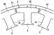
- FIG. 16 shows a state of stress generation in each divided core 6 when a plurality of divided cores 6 are attached in an annular shape on the inner peripheral surface of the cylindrical portion 51 of the retaining ring 5 of the stator.
- Each of the split cores 6 has a tooth portion 61 around which a coil (not shown) is wound, and a back yoke portion 62 connected to the outside of the tooth portion 61 in the radial direction.
- the split cores 6 that are adjacent to each other have a predetermined tightening margin (the outer diameter of the split core 6 minus the outer diameter of the split core 6) in a state where the circumferential ends of the back yoke portion 62 are in contact with each other.
- the inner diameter of the cylindrical portion 51 of the retaining ring 5 is press-fitted.
- each back yoke portion 62 is radially inward from the inner peripheral surface of the cylindrical portion 51 of the retaining ring 5 by press-fitting the retaining core 5 into the cylindrical portion 51 of the split core 6. Is subjected to substantially equal pressing force (surface pressure). Further, both end portions of the back yoke portion 62 receive a circumferential pressing force from the back yoke portion 62 of the adjacent split core 6. Therefore, compressive stress is easily generated in the back yoke portion 62.
- each member of the rotating electrical machine has a variation in dimensions, and the above-described tightening allowance varies due to the variation. If the dimensions of each member are set so that the above-described predetermined tightening allowance is maintained even in the worst case in consideration of dimensional variations, if the tightening allowance increases, the inside of the cylindrical portion 51 of the retaining ring 5 The surface pressure applied from the peripheral surface to the outer peripheral surface of the back yoke portion 62 increases. And when the stress which generate
- each divided core 6 is formed by laminating a large number of thin electromagnetic steel plates, so that buckling of the back yoke portion 62, that is, deformation in which the back yoke portion 62 is bent in the axial direction due to a compressive load occurs.
- the electric machine may be damaged.
- the contact pressure applied from the inner peripheral surface of the cylindrical portion 51 of the retaining ring 5 to the outer peripheral surface of the back yoke portion 62 can be reduced by reducing the thickness of the cylindrical portion 51 of the retaining ring 5.
- the cylindrical portion 51 of the retaining ring 5 breaks when the plurality of split cores 6 are press-fitted or shrink-fitted into the inner peripheral portion of the cylindrical portion 51 of the retaining ring 5. There is a fear.
- the present invention has been made in view of the above circumstances, and its purpose is to reduce the iron loss inside the core due to the surface pressure from the holding ring while maintaining the holding force of the split core by the holding ring, and An object of the present invention is to provide a rotating electrical machine that prevents buckling.
- an invention according to claim 1 includes a rotor that is rotatably attached to a housing, a radially outer side facing the rotor, and a cylindrical portion.
- a holding ring attached to the housing, and a stator plate having a plurality of divided cores, each of which is configured by laminating a core plate made of electromagnetic steel plate, each of which is wound with a coil and fixed to the inner peripheral surface of the cylindrical portion;
- Each of the split cores extends in a radial direction in a state of being attached to the holding ring, and is connected to a tooth portion around which a coil is wound, and radially outward of the tooth portion, A plurality of the split cores in a state where end surfaces of the adjacent back yoke portions are in contact with each other and arranged in an annular shape.
- a rotating electric machine that is fitted to the holding ring by applying a surface pressure to the inner periphery of the cylindrical portion of the ring with a tightening margin by press fitting or shrink fitting, and a slit is formed in the back yoke portion of the split core That is, the back yoke portion is provided so as to penetrate both ends in the circumferential direction.
- the slit is configured such that the distance from the slit to the outer periphery of the back yoke portion is the same as the distance from the inner periphery to the outer periphery of the cylindrical portion of the holding ring. Is formed.
- the slit extends from the slit to the outer periphery of the back yoke portion with respect to the distance from the inner periphery to the outer periphery of the cylindrical portion of the holding ring. That is, the distance ratio is increased.
- the laminated electromagnetic steel sheets are doubly crimped between the slit and the outer periphery of the back yoke portion. It is that you are.
- the divided core is formed by bonding the laminated electromagnetic steel sheets between the slit and the outer periphery of the back yoke portion. It is that you are.
- a rotor that is rotatably attached to a housing, a holding ring that is provided radially opposite to the rotor, has a cylindrical portion, and is attached to the housing;
- a stator plate having a plurality of divided cores, each of which is configured by laminating core plates made of electromagnetic steel plates, each of which is wound with a coil and fixed to the inner peripheral surface of the cylindrical portion.
- a tooth portion that extends in the radial direction and is wound with a coil
- a back yoke portion that is connected radially outward of the teeth portion and extends in the circumferential direction
- the plurality of split cores are press-fitted into the inner periphery of the cylindrical portion of the holding ring in a state where the end surfaces of the adjacent back yoke portions are in contact with each other and arranged in an annular shape.
- a surface pressure is applied to the retaining ring with a tightening margin by fitting, and at least at the center portion in the circumferential direction of the back yoke portion, the back yoke portion has a slit whose longitudinal direction is the circumferential direction. Is formed.
- the invention according to claim 7 is that, in claim 6, the length of the slit in the circumferential direction is equal to or greater than the circumferential length of the teeth portion.
- the slit is formed in an outer peripheral edge portion of the back yoke portion.
- each of the divided cores is formed by laminating a plurality of first core plates and a plurality of second core plates in a predetermined order.
- the first core plate is formed such that an outer periphery of the first core plate protrudes radially outward from an outer periphery of the second core plate, and is formed on the back yoke portion of the first core plate.
- the slits are provided so as to leave both circumferential ends of the back yoke portion.
- the invention according to claim 10 is the invention according to claim 9, wherein the first core plate is formed such that a distance from an outer periphery of the first core plate to an outer periphery of the second core plate is equal to or more than the tightening allowance. It is that you are.
- the plurality of divided cores contact each other in the circumferential direction end surfaces of the back yoke portion of the first core plate that respectively constitute the divided cores adjacent to each other.
- the first core plate and the second core plate are laminated in a predetermined order so that the position and the joining position of the circumferential end faces of the back yoke portion of the second core plate are shifted in the circumferential direction. It is fitted to the holding ring.
- the plurality of divided cores are arranged in the circumferential direction of the back yoke portion of the first core plate that constitutes the divided cores adjacent to each other.
- the first core plate and the second core plate are laminated in a predetermined order so that the end surfaces are in contact with each other and a gap is formed between the circumferential end surfaces of the back yoke portion of the second core plate. It is fitted to the holding ring.
- the slit is formed in the first core plate by press work, and the plurality of first core plates and the plurality of the first core plates stacked.
- the two-core plate is squeezed.
- a notch for positioning at the time of stacking with the second core plate is formed on the outer periphery of the first core plate. It is formed so as to reach the outer periphery of the core plate.
- the divided core in which the plurality of first core plates and the plurality of second core plates are laminated in a predetermined order is provided at both ends. That is, the second core plate is configured by being laminated.
- a rotor that is rotatably attached to a housing, a holding ring that is provided radially opposite to the rotor, has a cylindrical portion, and is attached to the housing.
- a stator plate having a plurality of divided cores, each of which is configured by laminating core plates made of electromagnetic steel plates, each of which is wound with a coil and fixed to the inner peripheral surface of the cylindrical portion.
- a teeth portion that extends in a radial direction and is wound with a coil in a state of being attached to the retaining ring, and a back yoke portion that is connected radially outward of the teeth portion and extends in the circumferential direction.
- the plurality of split cores are press-fitted into the inner periphery of the cylindrical portion of the holding ring in a state where end surfaces of the adjacent back yoke portions are in contact with each other and arranged in an annular shape.
- a surface pressure is applied to the holding ring with a tightening margin by fitting, and each of the divided cores includes a plurality of first core plates and a plurality of second core plates stacked in a predetermined order.
- the first core plate is formed such that an outer periphery of the first core plate protrudes radially outward from an outer periphery of the second core plate, and at least the back of the first core plate is formed.
- a slit having a longitudinal direction in the circumferential direction is formed in the back yoke portion.
- the invention according to claim 17 is the invention according to claim 16, wherein the length of the slit in the circumferential direction is equal to or greater than the circumferential length of the teeth portion of the first core plate.
- the slit is formed in an outer peripheral edge portion of the back yoke portion of the first core plate.
- the slit is provided in the back yoke portion of the split core so as to leave both circumferential ends of the back yoke portion.
- the slit serves as a buffer portion, and the portion between the slit and the outer periphery of the back yoke portion (hereinafter referred to as the bridge portion) receives most of the surface pressure from the cylindrical portion of the retaining ring.
- the stress generated by reducing the surface pressure received by the back yoke portion excluding the portion from the cylindrical portion of the retaining ring can be reduced.
- the slit is a distance from the slit to the outer periphery of the back yoke portion, that is, a radial thickness of the bridge portion, and a distance from the inner periphery to the outer periphery of the cylindrical portion of the holding ring, that is, The cylindrical portion of the retaining ring is formed so as to have the same thickness in the radial direction.
- the radial thickness of the cylindrical portion of the retaining ring can be made thinner than the radial thickness of the conventional cylindrical portion, and as a result Further, the outer diameter of the split core can be widened by reducing the thickness of the cylindrical portion in the radial direction, and a bridge portion can be formed at that portion.
- the outer diameter of the cylindrical part of the retaining ring cannot be increased beyond a certain level.
- the outer diameter of the retaining ring's cylindrical part remains the same as that of the conventional cylindrical part.
- the thickness of the cylindrical portion in the radial direction is, for example, 1 ⁇ 2 of the radial thickness of the conventional cylindrical portion, and the outer diameter of the split core is increased by 1 ⁇ 2 of the radial thickness of the conventional cylindrical portion.
- a bridge portion is formed in the portion so that the rigidity of the cylindrical portion of the holding ring and the rigidity of the bridge portion can be made substantially equal, and the bridge portion can receive most of the surface pressure from the cylindrical portion of the holding ring.
- the size of the rotating electrical machine remains the same as the size of the conventional rotating electrical machine, the area (volume) of the back yoke part other than the bridge part is substantially the same as the conventional one, and the magnetic flux flow can be ensured and maintained as before. Maintaining the holding power of the split core by the ring, improving the efficiency of the rotating electrical machine by reducing the iron loss inside the back yoke part, and preventing the rotating electrical machine from being damaged by preventing buckling of the back yoke part can be achieved.
- the slit increases in the distance from the inner periphery to the outer periphery of the cylindrical portion of the retaining ring, that is, in the radial direction of the cylindrical portion of the retaining ring.
- the distance from the slit to the outer periphery of the back yoke part that is, the ratio of the thickness of the bridge part in the radial direction is increased.
- the laminated electromagnetic steel plates are squeezed between the slit and the outer periphery of the back yoke portion.
- a back yoke part especially a bridge
- the laminated electromagnetic steel sheets are bonded to each other from the slit to the outer periphery of the back yoke portion. This prevents the back yoke part, especially the bridge part from buckling and bending in the axial direction even when the radial thickness of the bridge part is thin and cannot be squeezed. Can be prevented.
- the slit is formed so that the circumferential direction is the longitudinal direction at least in the central portion of the back yoke portion in the circumferential direction.
- the slit serves as a buffer portion and the bridge portion receives most of the surface pressure from the cylindrical portion of the holding ring, so that the back yoke portion excluding the bridge portion receives the surface pressure received from the cylindrical portion of the holding ring. The stress generated by the reduction can be reduced.
- the slit is formed such that its circumferential length is equal to or greater than the circumferential length of the tooth portion.
- the longer the slit is in the circumferential direction the lower the surface pressure that the back yoke part excluding the bridge part receives from the cylindrical part of the retaining ring, thereby reducing the generated stress. Therefore, the iron loss inside the back yoke portion can be further reduced to greatly improve the efficiency of the rotating electrical machine, and buckling of the back yoke portion can be prevented to prevent the rotating electrical machine from being damaged.
- the slit is provided through the outer peripheral edge portion of the back yoke portion of the split core. Accordingly, the surface pressure from the cylindrical portion of the holding ring is received only by the bridge portion provided at the outer peripheral edge portion of the back yoke portion, so that the surface pressure received from the cylindrical portion of the holding ring in the majority of the back yoke portion. It is possible to reduce the generated stress. Therefore, it is possible to achieve both the maintenance of the holding force of the split core by the retaining ring, the improvement of the efficiency of the rotating electrical machine by reducing the iron loss inside the back yoke part, and the prevention of damage to the rotating electrical machine by preventing buckling of the back yoke part. it can.
- each divided core is configured by laminating a plurality of first core plates and a plurality of second core plates in a predetermined order, and the first core plate
- the outer periphery of the first core plate is formed so as to protrude outward in the radial direction from the outer periphery of the second core plate, and slits are provided in the back yoke portion of the first core plate, leaving both end portions in the circumferential direction of the back yoke portion.
- the surface pressure from the cylindrical portion of the holding ring is received only by the back yoke portion of the first core plate protruding from the back yoke portion of the second core plate.
- the slit formed in the first core plate serves as a buffer portion, and a portion between the slit and the outer periphery of the back yoke portion of the first core plate (hereinafter referred to as a bridge portion) is separated from the cylindrical portion of the holding ring. Since the surface pressure is received, the stress generated by reducing the surface pressure received by the back yoke portion excluding the bridge portion from the cylindrical portion of the holding ring can be reduced.
- the first core plate that receives the surface pressure is sandwiched by the second core plate that does not receive the surface pressure and is fixed to the holding ring, the movement of the bridge portion in the axial direction can be suppressed. Even if it is not fixed by dowel crimping or adhesion, it is possible to prevent the bridge portion from buckling and bending in the axial direction. Therefore, it is possible to achieve both the maintenance of the holding force of the split core by the retaining ring, the improvement of the efficiency of the rotating electrical machine by reducing the iron loss inside the back yoke part, and the prevention of damage to the rotating electrical machine by preventing buckling of the back yoke part. it can.
- the first core plate is formed such that the distance from the outer periphery of the first core plate to the outer periphery of the second core plate is equal to or greater than the tightening allowance.
- the plurality of divided cores include the contact positions of the circumferential end surfaces of the back yoke portions of the first core plate that constitute the adjacent divided cores, and the back yoke of the second core plate.
- the first core plate and the second core plate are laminated in a predetermined order and fitted to the holding ring so that the joining positions of the circumferential end faces of the portions are shifted in the circumferential direction.
- the back yoke portion of the first core plate is sandwiched between the back yoke portions of the adjacent second core plates, so that the circumferential end surfaces of the back yoke portions of the first core plate are adjacent to each other.
- the core plate does not come into contact with the circumferential end surface of the back yoke portion, and the circumferential end surfaces of the back yoke portion can be reliably brought into contact with each other.
- the plurality of split cores are in contact with each other in the circumferential end surfaces of the back yoke portions of the first core plate constituting the adjacent split cores, and the back yoke portions of the second core plate.
- the first core plate and the second core plate are laminated in a predetermined order and are fitted to the holding ring so that a gap is generated between the circumferential end faces.
- the surface pressure from the cylindrical portion of the retaining ring hardly propagates between the back yoke portions of the second core plate that constitute the mutually adjacent divided cores, and the inside of the back yoke portion of the second core plate. An increase in iron loss can be prevented.
- the slit is formed in the first core plate by press working, and the plurality of stacked first core plates and the plurality of second core plates are doubly crimped.
- the bridge portion is buckled by a compressive load received from the cylindrical portion of the retaining ring, and is easily bent in the axial direction.
- the first core plate that receives the surface pressure is sandwiched by the second core plate that does not receive the surface pressure and is fixed to the holding ring, the axial movement of the bridge portion is suppressed to prevent buckling.
- the radial width of the slit can be widened so that it can be pressed. Therefore, since the formation of the slits and the formation of the concave and convex portions on the front and back surfaces of the first core plate and the second core plate can be handled only by a series of pressing processes, the manufacturing cost of the split core can be reduced.
- the outer periphery of the first core plate is formed with a positioning notch for stacking with the second core plate so as to reach the outer periphery of the second core plate.
- the plurality of first core plates and the plurality of second core plates are stacked in a mold, and the outer periphery of the first core plate protrudes radially outward from the outer periphery of the second core plate.
- the outer periphery of the first core plate contacts the inner wall of the mold, and the outer periphery of the second core plate does not contact the inner wall of the mold. For this reason, it becomes difficult to laminate the plurality of first core plates and the plurality of second core plates with high accuracy in the mold.
- the positioning notch reaching the outer periphery of the second core plate is formed on the outer periphery of the first core plate, by providing a positioning member that fits into the positioning notch on the inner wall of the mold, The plurality of first core plates and the plurality of second core plates can be stacked with high accuracy in the mold.
- the stacked divided cores are configured by stacking the second core plates on both ends.
- the first core plate is sandwiched on the inner layer side of the second core plate at both ends of the stack, so that the axial movement of the bridge portion of the first core plate can be suppressed, and the bridge portion buckles and axially Can be prevented from being bent.
- each divided core is configured by laminating a plurality of first core plates and a plurality of second core plates in a predetermined order.
- the outer periphery of the one core plate is formed so as to protrude outward in the radial direction from the outer periphery of the second core plate, and at least a slit whose circumferential direction is the longitudinal direction is formed at a central portion in the circumferential direction of the back yoke portion.
- the slit formed in the first core plate serves as a buffer portion, and the bridge portion receives the surface pressure from the cylindrical portion of the holding ring. Therefore, the back yoke portion excluding the bridge portion is separated from the cylindrical portion of the holding ring. It is possible to reduce the stress generated by reducing the contact pressure.
- the first core plate that receives the surface pressure is sandwiched by the second core plate that does not receive the surface pressure and is fixed to the holding ring, the movement of the bridge portion in the axial direction can be suppressed. Even if it is not fixed by dowel crimping or adhesion, it is possible to prevent the bridge portion from buckling and bending in the axial direction. Therefore, it is possible to achieve both the maintenance of the holding force of the split core by the retaining ring, the improvement of the efficiency of the rotating electrical machine by reducing the iron loss inside the back yoke part, and the prevention of damage to the rotating electrical machine by preventing buckling of the back yoke part. it can.
- the slit is formed such that its circumferential length is equal to or greater than the circumferential length of the tooth portion of the first core plate.
- the longer the slit is in the circumferential direction the lower the surface pressure that the back yoke part of the first core plate excluding the bridge part receives from the cylindrical part of the holding ring, and the stress generated can be reduced. Therefore, the iron loss inside the back yoke portion of the first core plate can be further reduced to greatly improve the efficiency of the rotating electrical machine, and the back yoke portion of the first core plate can be prevented from buckling and the rotating electrical machine can be prevented. Can prevent damage.
- the slit is provided through the outer peripheral edge portion of the back yoke portion of the first core plate. Accordingly, the surface pressure from the cylindrical portion of the holding ring is received only by the bridge portion provided at the outer peripheral edge portion of the back yoke portion, so that the surface pressure received from the cylindrical portion of the holding ring in the majority of the back yoke portion. It is possible to reduce the generated stress. Therefore, it is possible to achieve both the maintenance of the holding force of the split core by the retaining ring, the improvement of the efficiency of the rotating electrical machine by reducing the iron loss inside the back yoke part, and the prevention of damage to the rotating electrical machine by preventing buckling of the back yoke part. it can.
- FIG. 3 is a plan view of a single split core included in the stator shown in FIG. 2.
- A is a figure which shows the relationship between the tightening allowance of the cylindrical part and division
- B is the cylindrical part of the holding ring of the conventional rotary electric machine, It is a figure which shows the relationship between the interference with a division
- FIG. 7 shows the minimum principal stress distribution, the magnetic flux density distribution, and the iron loss density distribution generated when the split core of the rotating electrical machine of this embodiment is attached to the holding ring. It is a figure which shows the result analyzed using the method (FEM).
- FEM the method
- FIG. 8 shows the result analyzed using FEM. It is a top view of the stator of the rotary electric machine of 2nd Embodiment.
- FIG. 8 is an exploded perspective view of a single split core included in the stator shown in FIG. 7.
- (A) is a figure which shows the relationship between the tightening allowance of the cylindrical part and division
- (B) is the cylindrical part of the holding ring of the conventional rotary electric machine, It is a figure which shows the relationship between the interference with a division
- (A) Analyzes the minimum principal stress distribution, magnetic flux density distribution, and iron loss density distribution generated when the split core of the rotating electrical machine of this embodiment is attached to the retaining ring, using the finite element method (FEM).
- FEM finite element method
- 5B is a finite element method (FEM) showing the minimum principal stress distribution, magnetic flux density distribution and iron loss density distribution generated when a split core of a conventional rotating electrical machine is attached to a retaining ring. It is a figure which shows the result analyzed using. It is a schematic diagram for demonstrating the mechanism in which a stress generate
- FEM finite element method
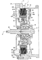
- the rotating electrical machine 1 is a synchronous motor for driving wheels of a hybrid vehicle.
- the left side is sometimes referred to as the front of the rotating electrical machine 1 and the clutch device 3, and the right side is sometimes referred to as the rear, but is not related to the actual direction on the vehicle.
- the direction of the rotation axis or the axial direction means the direction along the rotation axis C of the rotating electrical machine 1, that is, the left-right direction in FIG. 2 and 3, the bobbins 162 and 163 and the coil 164 fitted to the split core 16 are omitted.
- the motor housing 11 (corresponding to the “housing” of the present invention) is sealed with a motor cover 12 at the front in a state in which the rotor 13 and the stator 14 constituting the rotating electrical machine 1 are incorporated. Yes.
- a vehicle engine (not shown) is attached to the front of the motor cover 12, and a transmission (not shown) is disposed behind the motor housing 11.
- a normally closed type clutch device 3 that is a wet multi-plate clutch is interposed between the rotor 13 and the engine.
- the rotating electrical machine 1 is connected to driving wheels of a vehicle (not shown) via a transmission, and the driving force by the rotating electrical machine 1 is input to the driving wheels.
- the engine rotates the drive wheels via the transmission.
- the rotating electrical machine 1 can be operated to assist the engine.
- the rotary electric machine 1 rotates a driving wheel via a transmission.
- the clutch device 3 is released, and the connection between the engine and the rotating electrical machine 1 is released. Further, the rotating electrical machine 1 is driven by the engine via the clutch device 3 and also functions as a generator.
- the input shaft 32 of the clutch device 3 is attached to the inner peripheral end of the motor cover 12 via a bearing 31 so as to be rotatable about the rotation axis C.
- the rotating shaft C is also the rotating shaft of the turbine shaft 2 of the engine, the rotating electrical machine 1 and the transmission.
- the input shaft 32 is connected to the crankshaft of the engine.
- the input shaft 32 is connected to the clutch outer 34 via the engaging portion 33 of the clutch device 3. By engaging / disengaging the engaging portion 33, the input shaft 32 and the clutch outer 34 are intermittently connected.
- the clutch outer 34 is connected to the rotor 13 of the rotating electrical machine 1, extends radially inward, and is splined to the turbine shaft 2 at the inner end.
- a bearing device 35 is interposed between the clutch outer 34 and the fixed wall 111 of the motor housing 11 so as to allow relative rotation between the two.
- the rotor 13 of the rotating electrical machine 1 is rotatably attached to the motor housing 11 via a clutch outer 34.
- the rotor 13 is formed by sandwiching a plurality of laminated electromagnetic steel plates 131 between a pair of holding plates 132a and 132b, and penetrating a fixing member 133 therebetween to caulk the ends.
- a plurality of field pole magnets (not shown) are provided on the circumference of the rotor 13.
- One holding plate 132 b is attached to the clutch outer 34, whereby the rotor 13 is connected to the clutch outer 34.
- the stator 14 of the rotating electrical machine 1 is attached to the inner peripheral surface of the motor housing 11 so as to face the rotor 13 in the radial direction.
- the stator 14 is formed by fitting a plurality of split cores 16 for generating a rotating magnetic field on the inner peripheral surface of the retaining ring 15 with a surface pressure applied by shrink fitting so as to be arranged in an annular shape. (Shown in FIG. 2).
- the holding ring 15 is formed by press-molding a steel plate, and is connected to a ring-shaped cylindrical portion 151 and one end portion of the cylindrical portion 151 in the axial direction, and radially outward over the entire circumference. Further, mounting flanges 153 that extend further outward in the radial direction are formed at three locations on the circumference of the outer peripheral flange 152 (shown in FIG. 2).
- the mounting flange 153 is formed to mount the stator 14 to the motor housing 11, and each has one mounting hole 154 or one mounting hole 154 and one positioning hole 155 passing therethrough (see FIG. 2).
- a portion where the cylindrical portion 151 is connected to the outer peripheral flange 152 and the mounting flange 153 is formed into a curved surface having a predetermined curvature over the entire periphery.
- each divided core 16 includes a tooth portion 161a formed by laminating a plurality of silicon steel plates (electromagnetic steel plates).
- a pair of bobbins 162 and 163 are attached to the teeth portion 161a, and the bobbins 162 and 163 are fitted to each other so as to surround the outer peripheral surface of the teeth portion 161a.
- a coil 164 for generating a rotating magnetic field is wound around the bobbins 162 and 163.
- the coil 164 wound around the tooth portion 161a is connected to an external inverter via a bus ring (not shown).
- a rotating magnetic field is generated in the stator 14 by supplying, for example, a three-phase alternating current to the coil 164, and the rotor 13 is caused by the attractive force or repulsive force caused by the rotating magnetic field. It is rotated relative to the stator 14.
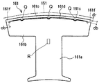
- each divided core 16 has an approximately T-shape.
- the plurality of split cores 16 attached to the holding ring 15 are arranged in an annular shape by abutting the end portions of the back yoke portion 161b with each other to form a core row CR (see FIG. 2).
- each of the split cores 16 is formed with a slit 161d whose longitudinal direction is the circumferential direction at least in the central portion in the circumferential direction of the back yoke portion 161b. That is, at the outer peripheral edge portion located radially inward from the outer peripheral surface 161c of the back yoke portion 161b, it extends in the circumferential direction leaving both circumferential ends of the back yoke portion 161b, and the back yoke portion A slit 161d penetrating 161b in the axial direction is formed (shown in FIGS. 2 and 3).
- Each slit 161d is formed so that the length in the circumferential direction is equal to or greater than the circumferential length of the tooth portion 161a.
- the slit 161d formed in the back yoke portion 161b should not be limited to the shape shown in FIG. 3, and various shapes can be applied as long as they extend in the circumferential direction on the back yoke portion 161b. It is.
- each bridge portion 161e receives most of the surface pressure from the cylindrical portion 151 of the holding ring 15 with each slit 161d serving as a buffer portion. (Shown in FIG. 2).
- the distance from the slit 161d to the outer peripheral surface 161c of the back yoke portion 161b, that is, the radial thickness db of the bridge portion 161e the distance from the inner periphery to the outer periphery of the cylindrical portion 151 of the holding ring 15, that is, the thickness dr of the cylindrical portion 151 of the holding ring 15 is formed to be the same (shown in FIG. 3).
- each slit 161d is formed so that the ratio of the thickness db in the radial direction of the bridge portion 161e to the thickness dr of the cylindrical portion 151 of the holding ring 15 is increased, thereby improving the strength of the bridge portion 161e. Even if the surface pressure from the cylindrical portion 151 of the ring 15 increases, most of the surface pressure can be received, and the stress generated in the back yoke portion 161b excluding the bridge portion 161e can be reduced.
- Each of the slits 161d has a rotational torque applied to the split core 16 when the rotating electrical machine 1 rotates at a portion from the end of the slit 161d to the end of the back yoke portion 161b (hereinafter referred to as the bridge leg portion 161f).
- the vehicle is formed so as not to be broken by an axial force applied to the split core 16 when the vehicle collides with the side. That is, the circumferential length cb of the bridge leg 161f is determined from the above-described rotational torque and axial force (shown in FIG. 3).
- the bridge portion 161e since the bridge portion 161e receives a large part of the surface pressure from the cylindrical portion 151 of the holding ring 15 with the slit 161d serving as a buffer portion, the bridge portion 161e is bent in the axial direction by a compressive load. In order to prevent buckling, it is squeezed at three points Q (shown in FIG. 3). In addition, since the generated stress is reduced in the portion of the split core 16 other than the bridge portion 161e, it may be squeezed at one point R in the substantially central portion of the split core 16 (shown in FIG. 3). Moreover, when the thickness of the bridge part 161e is thin and it cannot do a caulking, it is good to adhere
- the plurality of divided cores 16 are attached to the inner peripheral surface of the cylindrical portion 151 by shrink fitting.
- the retaining ring 15 is heated to a predetermined temperature, and its inner diameter is expanded.
- the plurality of cores 16 are inserted in an annular shape by bringing the back yokes 161b of the cores 16 into contact with the heated cylindrical part 151. After the split cores 16 are inserted into the cylindrical portion 151, the holding ring 15 is cooled and contracted, and each split core 16 can be firmly held.
- the split core 16 is held in the holding ring 15 by press-fitting. Furthermore, when the split core 16 is held in the holding ring 15 by press-fitting, an adhesive may be interposed between the split core 16 and the cylindrical portion 151 to increase the holding force.
- the holding ring 15 to which the split core 16 is attached is fixed to the motor housing 11. After the mounting flange 153 is brought into contact with the boss 112 of the motor housing 11, the mounting bolt 17 is inserted into the mounting hole 154 and screwed into the boss 112, so that the mounting flange 153 is attached to the motor housing 11.
- FIG. 4A is a view showing the relationship between the fastening allowance V and the surface pressure P between the cylindrical portion 151 and the split core 16 of the holding ring 15 of the present embodiment
- FIG. 4B is a conventional holding ring 5. It is a figure which shows the relationship between the interference V and the surface pressure P of the cylindrical part 51 of this, and the division
- FIG. 5A, 5 ⁇ / b> B, and 5 ⁇ / b> C show the minimum principal stress distribution, magnetic flux density distribution, and iron loss density distribution generated when the split core 16 of this embodiment is attached to the retaining ring 15. It is a figure which shows the result analyzed using the element method (FEM).
- FEM element method
- 6A, 6B, and 6C show the minimum principal stress distribution, the magnetic flux density distribution, and the iron loss density distribution generated when the conventional split core 6 is attached to the retaining ring 5, and the finite element method is used. It is a figure which shows the result analyzed using (FEM). 5 and 6, the smaller the number assigned to the region, the higher the minimum principal stress, the magnetic flux density and the iron loss density, and the larger the number attached to the region, the minimum principal stress, the magnetic flux density and the iron. Loss density is low.
- the surface pressures P1 and P1 can hold the split cores 6 and 161 in the circumferential direction and the axial direction with respect to the cylindrical portions 51 and 151 of the holding rings 5 and 15, that is, the holding ring.
- the divided cores 6 and 161 do not rotate in the circumferential direction with respect to the 5 and 15 cylindrical portions 51 and 151, and represent the minimum surface pressure that does not come off in the axial direction.
- the surface pressures P2 and P3 represent the tensile limit of the cylindrical portions 51 and 151 of the retaining rings 5 and 15, that is, the maximum surface pressure at which the cylindrical portions 51 and 151 of the retaining rings 5 and 15 break.
- the axial cross-sectional area of the cylindrical portion 151 of the retaining ring 15 is approximately half of the axial sectional area of the cylindrical portion 51 of the conventional retaining ring 5, so the surface pressure P ⁇ b> 2 is the surface pressure. About half of P3.
- the bridge part 161e bends by the surface pressure P from the cylindrical part 151 of the holding ring 15, it is applied to the cylindrical part 151 of the holding ring 15 of this embodiment by the fastening margin V.
- the load is smaller than the load applied to the cylindrical portion 51 of the conventional holding ring 5 due to the same fastening allowance V.
- the tightening margin V even if the tightening margin V is increased, the increase in the surface pressure P can be suppressed. That is, in the past, the maximum contact pressure P31 ( ⁇ P3), for example, 5.2 MPa was reached when the tightening margin was set to V4, but in this embodiment, the tightening margin is 1.5 times larger than the tightening margin V4. When V2 is reached, the maximum surface pressure P21 ( ⁇ P2), which is half of the surface pressure P31, for example, 2.6 MPa is reached.
- the tightening allowance establishment range V1 to V2 of this embodiment for example, 0.074 mm to 0.48 mm ( ⁇ 0.406 mm) is used as the conventional allowance allowance establishment range V3 to V4, for example, 0.024 mm to 0.298 mm ( ( ⁇ 0.274 mm). Therefore, since the allowable range (processing tolerance) of the dimensional variation of each member of the rotating electrical machine 1 is wider than the conventional one, the surface pressure between the cylindrical portion 151 of the holding ring 15 and the split core 16 increases excessively. This can be suppressed.
- the stress generated in the back yoke portion 62 of the conventional split core 6 is as follows. Although the stress was excessive, for example, a compressive stress of 33.4 MPa (shown in FIG. 6A), the stress generated in the back yoke portion 161b of the split core 16 of the present embodiment is the bridge portion 161e (the length of the dotted line). Only the portion surrounded by the circle a) becomes an excessive stress, for example, a compressive stress of 33.4 MPa, and the stress of the other portions, particularly both ends of the back yoke portion 161b (portion surrounded by the dotted ellipse b) is reduced.
- a compressive stress of 33.4 MPa shown in FIG. 6A
- a compressive stress of 3.8 MPa (shown in FIG. 5A).
- the magnetic flux density (shown in FIG. 5B) at both ends of the back yoke portion 161b of the split core 16 of the present embodiment (portion surrounded by a dotted oval) is the back yoke portion 62 of the conventional split core 6.
- the magnetic flux density at both ends (portion surrounded by a dotted-line ellipse) is lower than that shown in FIG.
- the iron loss density (shown in FIG. 5C) at both ends of the back yoke portion 161b of the split core 16 of the present embodiment (portion surrounded by a dotted-line ellipse) is the back yoke portion of the conventional split core 6. It is more relaxed than the iron loss density (shown in FIG. 6C) at both ends of 62 (portion surrounded by a dotted oval).
- the slit 161d is provided in the back yoke portion 161b of the split core 16 so as to leave both circumferential ends of the back yoke portion 161b.
- the slit 161 d serves as a buffer portion, and the bridge portion 161 e receives most of the surface pressure from the cylindrical portion 151 of the holding ring 15, so that the back yoke portion 161 b excluding the bridge portion 161 e serves as the holding ring 15.
- the stress generated by reducing the surface pressure received from the cylindrical portion 151 can be reduced.
- the slit 161d is formed so that the radial thickness of the bridge portion 161e and the radial thickness of the cylindrical portion 151 of the holding ring 15 are the same. ing.
- the bridge portion 161e receives most of the surface pressure from the cylindrical portion 151 of the retaining ring 15. Therefore, the stress generated in the back yoke portion 161b excluding the bridge portion 161e can be reduced, for example, half of the stress generated conventionally.
- the radial thickness of the cylindrical portion 151 of the holding ring 15 is made thinner than the radial thickness of the conventional cylindrical portion 51.
- the outer diameter of the split core 16 can be widened by reducing the thickness of the cylindrical portion 151 in the radial direction, and the bridge portion 161e can be formed at that portion.
- the outer diameter of the cylindrical portion 151 of the retaining ring 15 cannot be increased beyond a certain level, but the outer diameter of the cylindrical portion 151 of the retaining ring 15 is the outer diameter of the conventional cylindrical portion 51.
- the radial thickness of the cylindrical portion 151 of the retaining ring 15 is, for example, 1 ⁇ 2 of the radial thickness of the conventional cylindrical portion 51, and the outer diameter of the split core 16 is set to the radius of the conventional cylindrical portion 51.
- the bridge portion 161e is formed by expanding the thickness by 1 ⁇ 2 of the thickness in the direction, and the rigidity of the cylindrical portion 151 of the holding ring 15 and the rigidity of the bridge portion 161e can be made substantially equal, and are held by the bridge portion 161e. Most of the surface pressure from the cylindrical portion 151 of the ring 15 can be received. Therefore, the size of the rotating electrical machine 1 remains the same as the size of the conventional rotating electrical machine, and the area (volume) of the back yoke portion 161b other than the bridge portion 161e is substantially the same as the conventional one to ensure the flow of magnetic flux as in the conventional case.
- the retaining ring 15 maintains the holding force of the split core 16, improves the efficiency of the rotating electrical machine 1 by reducing the iron loss inside the back yoke part 161b, and prevents the rotating electrical machine 1 from being damaged by preventing buckling of the back yoke part 161b. Can be made compatible.
- the slit 161d is a bridge portion with respect to the radial thickness of the cylindrical portion 151 of the retaining ring 15 as the surface pressure from the cylindrical portion 151 of the retaining ring 15 increases.
- 161e is formed so that the ratio of the thickness in the radial direction is increased.
- the strength of the bridge portion 161e is improved, so that even if the surface pressure from the cylindrical portion 151 of the retaining ring 15 is increased, most of the surface pressure can be received, and the back yoke portion 161b excluding the bridge portion 161e. It is possible to reduce the stress generated in.
- the divided cores 16 are stiffened between the laminated electromagnetic steel plates from the slit 161d to the outer peripheral surface 161c of the back yoke portion 161b.
- the back yoke portion 161b, in particular, the bridge portion 161e from buckling and bending in the axial direction, and to prevent the rotating electrical machine 1 from being damaged.
- stacked electromagnetic steel plates are adhere
- the back yoke portion 161b particularly the bridge portion 161e, can be prevented from buckling and bending in the axial direction. Damage to the electric machine 1 can be prevented.
- the slit 161d is formed so that the circumferential direction is the longitudinal direction at least in the circumferential central portion of the back yoke portion 161b.
- the slit 161 d serves as a buffer portion, and the bridge portion 161 e receives most of the surface pressure from the cylindrical portion 151 of the holding ring 15, so that the back yoke portion 161 b excluding the bridge portion 161 e serves as the holding ring 15.
- the stress generated by reducing the surface pressure received from the cylindrical portion 151 can be reduced.
- the slit 161d is formed such that its circumferential length is equal to or greater than the circumferential length of the tooth portion 161a.
- the longer the slit 161d is in the circumferential direction the lower the surface pressure that the back yoke portion 161b excluding the bridge portion 161e receives from the cylindrical portion 151 of the holding ring 15 can be reduced. Therefore, the iron loss inside the back yoke portion 161b can be further reduced to significantly improve the efficiency of the rotating electrical machine 1, and the buck yoke of the back yoke portion 161b can be prevented to prevent the rotating electrical machine 1 from being damaged. Can do.
- the slit 161d is provided through the edge of the outer peripheral surface 161c of the back yoke portion 161b of the split core 16.
- the surface pressure from the cylindrical portion 151 of the holding ring 15 is received only by the bridge portion 161e provided at the edge of the outer peripheral surface 161c of the back yoke portion 161b, so that the holding ring is mostly in the back yoke portion 161b.
- the stress generated by reducing the surface pressure received from the 15 cylindrical portions 151 can be reduced.
- the rotating electrical machine of the second embodiment has basically the same configuration as the rotating electrical machine 1 of the first embodiment shown in FIG.
- the same components as those of the rotating electrical machine 1 according to the first embodiment are denoted by the same reference numerals, and detailed description thereof is omitted.
- each split core 16 extends in the radial direction when attached to the holding ring 15, and is connected to the teeth portion 161 a around which the coil 164 is wound, and radially outward of the teeth portion 161 a. And a back yoke portion 161b extending in the circumferential direction (shown in FIG. 7).
- each divided core 16 has an approximately T-shape.
- the plurality of divided cores 16 attached to the holding ring 15 are arranged in an annular shape by abutting the end portions of the back yoke portion 161b with each other to form a core row CR.
- a pair of bobbins 162 and 163 are attached to the teeth portion 161a, and the bobbins 162 and 163 are fitted to each other so as to surround the outer peripheral surface of the teeth portion 161a. Further, a coil 164 for generating a rotating magnetic field is wound around the bobbins 162 and 163. The coil 164 wound around the tooth portion 161a is connected to an external inverter via a bus ring (not shown).
- a rotating magnetic field is generated in the stator 14 by supplying, for example, a three-phase alternating current to the coil 164, and the rotor 13 is caused by the attractive force or repulsive force caused by the rotating magnetic field. It is rotated relative to the stator 14.
- each of the divided cores 16 includes a first core plate 165 and a second core plate 166 made of silicon steel plates having two types of shapes, in a predetermined order, for example, one by one alternately, or an arbitrary number of sheets. It is formed by laminating a plurality of sheets alternately.
- the first core plate 165 is formed with a slit 165d whose longitudinal direction is the circumferential direction at least in the central portion in the circumferential direction of the first back yoke portion 165b.
- the first core plate 165 has an outer peripheral edge portion located radially inward by a predetermined distance from the outer periphery 165c of the portion constituting the back yoke portion 161b of the split core 16 (hereinafter referred to as the first back yoke portion 165b).
- a slit 165d that extends in the circumferential direction leaving both circumferential ends of the first back yoke portion 165b and penetrates the first back yoke portion 165b in the axial direction is formed.
- Each slit 165d is formed so that the length in the circumferential direction is equal to or greater than the circumferential length of the first tooth portion 165a of the first core plate 165.
- a portion corresponding to the slit 165d is not formed in a portion (hereinafter referred to as a second back yoke portion 166b) constituting the back yoke portion 161b of the split core 16 in the second core plate 166.
- each bridge portion 165e receives a surface pressure from the cylindrical portion 151 of the holding ring 15 with each slit 165d serving as a buffer portion ( Fig. 7). Therefore, when the same number of first core plates 165 and second core plates 166 are stacked, in order to halve the stress generated in the first back yoke portion 165b excluding the bridge portion 165e, for example, the first back from the slit 165d.
- the distance to the outer periphery 165c of the yoke portion 165b, that is, the radial thickness db of the bridge portion 165e is the distance from the inner periphery to the outer periphery of the cylindrical portion 151 of the retaining ring 15, that is, the thickness of the cylindrical portion 151 of the retaining ring 15. It is formed to be twice the dr.
- the slits 165d are formed so that the ratio of the thickness db in the radial direction of the bridge portion 165e to the thickness dr of the cylindrical portion 151 of the holding ring 15 is increased, thereby improving the strength of the bridge portion 165e. Even if the surface pressure from the cylindrical portion 151 of the ring 15 increases, the surface pressure can be received, and the stress generated in the first back yoke portion 165b excluding the bridge portion 165e can be reduced.
- each slit 165d is a portion of the slit 165d from the end portion of the first back yoke portion 165b (hereinafter referred to as a bridge leg portion 165f) that rotates on the split core 16 when the rotating electrical machine 1 rotates. It is formed so as not to be broken by torque or an axial force applied to the split core 16 when the vehicle collides with the side, for example. That is, the circumferential length cb of the bridge leg 165f is determined from the above-described rotational torque and axial force.
- the first core plate 165 has an outer periphery 165 c of the first back yoke portion 165 b of the first core plate 165, and the second back yoke portion 166 b of the second core plate 166.
- the outer periphery 166c is formed so as to protrude outward in the radial direction.
- the protruding length that is, the distance sb from the outer periphery 165c of the first back yoke portion 165b to the outer periphery 166c of the second back yoke portion 166b is formed to be equal to or greater than the tightening allowance with the cylindrical portion 151 of the holding ring 15. Yes.
- the plurality of split cores 16 are radially outward from the outer periphery 165c of the first back yoke portion 165b by a distance sb greater than the outer periphery 166c than the outer periphery 166c of the second back yoke portion 166b.
- the outer periphery 166c of the second back yoke portion 166b does not contact the inner peripheral surface of the cylindrical portion 151 of the holding ring 15, so that the first Only the outer periphery 165c of the back yoke portion 165b contacts.
- a portion constituting the tooth portion 161 a of the split core 16 in the first core plate 165 (hereinafter referred to as the first tooth portion 165 a) is split in the second core plate 166.
- the first back yoke portion 165b of the first core plate 165 is formed in the same shape as a portion constituting the tooth portion 161a of the core 16 (hereinafter referred to as the second tooth portion 166a).
- the lengths ub1 and ub2 of the outer peripheries 165c and 166c are substantially the same as the second back yoke portion 166b, and are formed to be shifted by a predetermined length vb in the circumferential direction.
- the plurality of divided cores 16 are in contact with the contact positions r1 between the circumferential end surfaces of the first back yoke portion 165b of the first core plate 165 constituting the divided cores 16 adjacent to each other.
- the first core plate 165 and the second core plate 166 are alternately stacked in a state where the joining position r2 between the circumferential end faces of the second back yoke portion 166b of the second core plate 166 is shifted in the circumferential direction. And is fitted to the cylindrical portion 151 of the holding ring 15.
- circumferential direction end surfaces of the adjacent 1st back yoke part 165b contact
- the circumferential direction end surfaces of the adjacent second back yoke portions 166b may be lightly joined, they may be joined with a minute gap.
- the second core plate 166 has a length ub2 of the outer periphery 166c of the second back yoke portion 166b of the second core plate 166, and a length ub1 of the outer periphery 165c of the first back yoke portion 165b of the first core plate 165. You may form so that it may become slightly shorter than. As a result, as shown in FIG. 12, the plurality of split cores 16 are in contact with each other in the circumferential direction end surfaces of the first back yoke portions 165b of the first core plates 165 constituting the split cores 16 adjacent to each other. The first core plate 165 and the second core plate 166 are alternately stacked in a state where a gap x is generated between the circumferential end faces of the second back yoke portion 166b of the core plate 166.
- each of the divided cores 16 includes a first core plate 165 and a second core plate 166 formed by punching electromagnetic steel sheets by press working, positioned in a mold 167, and sequentially stacked. It is formed by joining.
- the bridge portion 165e receives the surface pressure from the cylindrical portion 151 of the retaining ring 15 with the slit 165d serving as a buffer portion.
- the bridge portion 165e of the first core plate 165 is sandwiched between the second core plates 166, so that the occurrence of buckling in which the bridge portion 165e is bent in the axial direction due to a compressive load is prevented. Is done.
- the split core 16 when the split core 16 is formed in the mold 167, at least the lowermost layer and the uppermost core plate are the second core plates 166 that do not have the slits 165d, so that the bridge portion 165e that is easily buckled is formed. Since the first core plate 165 formed by the slits 165d is not disposed at both ends of the split core 16 where buckling is likely to occur, buckling of the bridge portion 165e can be prevented. For the above-described reason, it is not necessary to reinforce the bridge portion 165e and strengthen the strength.
- the two points Q in the circumferential direction inward in the radial direction and the point R at substantially the center of the first and second tooth portions 165a and 166a are connected by dowel caulking.
- the first core plate 165 has an outer periphery 165c of the first back yoke portion 165b protruding radially outward from the outer periphery 166c of the second back yoke portion 166b by a distance sb.
- two (or three) notches 165f for positioning when stacked with the second core plate 166 are provided on the outer periphery 165c of the first back yoke portion 165b of the first core plate 165.
- the two-core plate 166 is formed so as to reach the outer periphery 166c of the second back yoke portion 166b.
- first projecting portions as positioning members that enter the notch 165f into the die 167 and abut against the outer peripheries 165c, 166c of the first and second back yoke portions 165b, 166b.
- 167a and two second protrusions 167b are provided as positioning members that contact and position on both sides in the circumferential direction of the first and second teeth 165a, 166a.
- the first core plate 165 in the die 167 is also formed in the outer periphery 166c of the second back yoke portion 166b of the second core plate 166 by forming a minute notch at a position corresponding to the notch 165f.
- the positioning accuracy of the second core plate 166 with respect to can be further improved.
- the plurality of divided cores 16 are attached to the inner peripheral surface of the cylindrical portion 151 by shrink fitting.
- the retaining ring 15 is heated to a predetermined temperature, and its inner diameter is expanded.
- the plurality of cores 16 are inserted in an annular shape by bringing the back yokes 161b of the cores 16 into contact with the heated cylindrical part 151. After the split cores 16 are inserted into the cylindrical portion 151, the holding ring 15 is cooled and contracted, and each split core 16 can be firmly held.
- the split core 16 is held in the holding ring 15 by press-fitting. Furthermore, when the split core 16 is held in the holding ring 15 by press-fitting, an adhesive may be interposed between the split core 16 and the cylindrical portion 151 to increase the holding force.
- the holding ring 15 to which the split core 16 is attached is fixed to the motor housing 11. After the mounting flange 153 is brought into contact with the boss 112 of the motor housing 11, the mounting bolt 17 is inserted into the mounting hole 154 and screwed into the boss 112, so that the mounting flange 153 is attached to the motor housing 11.
- FIG. 14A is a diagram showing the relationship between the fastening allowance V and the surface pressure P between the cylindrical portion 151 and the split core 16 of the holding ring 15 of the present embodiment
- FIG. 14B is the conventional holding ring 5. It is a figure which shows the relationship between the interference V and the surface pressure P of the cylindrical part 51 of this, and the division
- FIG. FIG. 15A is a diagram illustrating a result of analyzing the minimum principal stress distribution generated when the split core 16 of the present embodiment is attached to the retaining ring 15 using a finite element method (FEM). The left half shows the minimum principal stress distribution of the first core plate 165, and the right half shows the minimum principal stress distribution of the second core plate 166.
- FEM finite element method
- 15B is a diagram showing a result of analyzing the minimum principal stress distribution generated when the conventional split core 6 is attached to the retaining ring 5 by using the finite element method (FEM).
- FEM finite element method
- the surface pressures P1 and P1 can hold the split cores 6 and 161 in the circumferential direction and the axial direction with respect to the cylindrical portions 51 and 151 of the holding rings 5 and 15, that is, the holding ring 5.
- 15 represents the minimum surface pressure at which the split cores 6 and 161 do not rotate in the circumferential direction and do not come off in the axial direction with respect to the cylindrical portions 51 and 151.
- the surface pressures P2 and P3 represent the tensile limit of the cylindrical portions 51 and 151 of the retaining rings 5 and 15, that is, the maximum surface pressure at which the cylindrical portions 51 and 151 of the retaining rings 5 and 15 break.
- the axial cross-sectional area of the cylindrical portion 151 of the retaining ring 15 is approximately half of the axial sectional area of the cylindrical portion 51 of the conventional retaining ring 5, so the surface pressure P ⁇ b> 2 is the surface pressure. About half of P3.
- the bridge part 161e bends by the surface pressure P from the cylindrical part 151 of the holding ring 15, it is applied to the cylindrical part 151 of the holding ring 15 of this embodiment by the fastening margin V.
- the load is smaller than the load applied to the cylindrical portion 51 of the conventional holding ring 5 due to the same fastening allowance V.
- the fastening allowance establishment range V1 to V2 of the present embodiment can be expanded from the conventional fastening allowance establishment range V3 to V4.
- the allowable range (processing tolerance) of the dimensional variation of each member of the rotating electrical machine 1 is wider than the conventional one, the surface pressure between the cylindrical portion 151 of the holding ring 15 and the split core 16 increases excessively. This can be suppressed.
- the stress generated in the back yoke portion 62 of the conventional split core 6 is excessive stress (compressive stress) (FIG. 15B).
- the stress generated in the back yoke portion 161b of the split core 16 of this embodiment is an excessive stress (compressive stress) in the bridge portion 165e of the first core plate 165 (portion surrounded by the dotted oval a).
- the other portions in particular, the center portion of the first back yoke portion 165b of the first core plate 165 (the portion surrounded by the dotted ellipse b) and the second teeth portion 166a and the second back yoke of the second core plate 166
- the stress of the portion 166b becomes extremely reduced stress (compressive stress) (shown in FIG. 15A). Therefore, the iron loss of the back yoke part 161b of the split core 16 of this embodiment is reduced more than the iron loss of the back yoke part 62 of the conventional split core 6.
- each divided core 16 includes a plurality of first core plates 165 and a plurality of second core plates 166 stacked in a predetermined order.
- the first core plate 165 is formed such that the outer periphery 165c of the first core plate 165 protrudes radially outward from the outer periphery 166c of the second core plate 166.
- a slit 165d is provided in one back yoke portion 165b so as to penetrate both ends in the circumferential direction of the first back yoke portion 165b.
- the surface pressure from the cylindrical portion 151 of the holding ring 15 is received only by the first back yoke portion 165b of the first core plate 165 protruding from the second back yoke portion 166b of the second core plate 166.
- the slit 165d formed in the first core plate 165 serves as a buffer portion, and the bridge portion 165e receives the surface pressure from the cylindrical portion 151 of the holding ring 15. Therefore, the first back yoke excluding the bridge portion 165e is used.
- the stress generated by reducing the surface pressure that the portion 165b receives from the cylindrical portion 151 of the retaining ring 15 can be reduced.
- the first core plate 165 that receives the surface pressure is sandwiched by the second core plate 166 that does not receive the surface pressure and is fixed to the holding ring 15, the axial movement of the bridge portion 165e can be suppressed. Even if the bridge portions 165e are not fixed to each other by doweling or bonding, the bridge portion 165e can be prevented from buckling and bending in the axial direction. Therefore, maintaining the holding force of the split core 16 by the retaining ring 15, improving the efficiency of the rotating electrical machine 1 by reducing the iron loss inside the back yoke part 161b, and preventing damage to the rotating electrical machine 1 by preventing buckling of the back yoke part 161b. Can be made compatible.
- the slit 165d has a radial thickness of the bridge portion 165e that is twice the radial thickness of the cylindrical portion 151 of the holding ring 15. Is formed.
- the bridge portion 165e receives a surface pressure from the cylindrical portion 151 of the retaining ring 15.
- the thickness of the bridge portion 165e in the radial direction is increased.
- the stress generated in the first back yoke portion 165b excluding the bridge portion 165e is reduced, for example, half of the stress generated conventionally. Can be.
- the radial thickness of the cylindrical portion 151 of the holding ring 15 is made thinner than the radial thickness of the conventional cylindrical portion 51.
- the outer diameter of the split core 16 can be widened by reducing the thickness of the cylindrical portion 151 in the radial direction, and the bridge portion 165e can be formed at that portion.
- the outer diameter of the cylindrical portion 151 of the retaining ring 15 cannot be increased beyond a certain level, but the outer diameter of the cylindrical portion 151 of the retaining ring 15 is the outer diameter of the conventional cylindrical portion 51.
- the radial thickness of the cylindrical portion 151 of the retaining ring 15 is, for example, 1 ⁇ 2 of the radial thickness of the conventional cylindrical portion 51, and the outer diameter of the split core 16 is set to the radius of the conventional cylindrical portion 51.
- the bridge portion 165e having a thickness twice as large as the radial thickness of the conventional cylindrical portion 51 is formed, and the rigidity of the cylindrical portion 151 of the retaining ring 15 and the bridge portion 165e are increased.
- the rigidity can be made substantially equal, and the bridge portion 165e can receive the surface pressure from the cylindrical portion 151 of the holding ring 15. Since the first core plate 165 having the bridge portion 165e is sandwiched between the second core plates 166 without the bridge portion 165e, the thickness of the bridge portion 165e is twice the radial thickness of the conventional cylindrical portion 51. Thus, even if the iron loss of the bridge portion 165e becomes large, there is no particular problem without affecting the overall iron loss. Therefore, the size of the rotating electrical machine 1 remains the same as the size of the conventional rotating electrical machine, the area (volume) of the first back yoke portion 165b other than the bridge portion 165e is substantially the same as the conventional one, and the flow of magnetic flux is the same as the conventional one.
- the slit 165d has a bridge portion with respect to the radial thickness of the cylindrical portion 151 of the holding ring 15 as the surface pressure from the cylindrical portion 151 of the holding ring 15 increases. It is formed so that the ratio of the thickness of 165e in the radial direction is increased. As a result, the strength of the bridge portion 165e is improved, so even if the surface pressure from the cylindrical portion 151 of the retaining ring 15 increases, the surface pressure can be received, and the first back yoke portion 165b excluding the bridge portion 165e The generated stress can be reduced.
- the distance sb from the outer periphery 165c of the first core plate 165 to the outer periphery 166c of the second core plate 166 is equal to or greater than the tightening margin. It is formed as follows. As a result, the surface pressure from the cylindrical portion 151 of the holding ring 15 is not always applied to the second back yoke portion 166b of the second core plate 166, and is received only by the first back yoke portion 165b of the first core plate 165. Therefore, the stress generated in the second back yoke part 166b of the second core plate 166 can be reliably reduced, and the iron loss inside the second back yoke part 166b of the second core plate 166 can be reduced.
- the plurality of divided cores 16 are arranged between the circumferential end faces of the first back yoke portion 165b of the first core plate 165 that constitutes the divided cores 16 adjacent to each other.
- the first core plate 165 and the second core plate 166 are predetermined so that the contact position r1 and the joining position r2 between the circumferential end surfaces of the second back yoke portion 166b of the second core plate 166 are shifted in the circumferential direction.
- the layers are laminated in order and fitted to the holding ring 15.
- the first back yoke portion 165b of the first core plate 165 is sandwiched between the first back yoke portions 166b of the adjacent second core plate 166. Therefore, the first back yoke of the first core plate 165 The circumferential end surface of the portion 165b does not hit against the circumferential end surface of the second back yoke portion 166b of the adjacent second core plate 166, and the circumferential end surfaces of the second back yoke portion 166b are reliably in contact with each other. can do.
- the plurality of divided cores 16 have the circumferential end surfaces of the first back yoke portion 165b of the first core plate 165 constituting the divided cores 16 adjacent to each other.
- the first core plate 165 and the second core plate 166 are configured and held in a predetermined order so that a space is generated between the circumferential end surfaces of the second back yoke portion 166b of the second core plate 166 in contact with each other. It is fitted to the ring 15.
- the surface pressure from the cylindrical portion 151 of the retaining ring 15 hardly propagates between the second back yoke portions 166b of the second core plates 166 constituting the adjacent divided cores 16, respectively.
- An increase in iron loss inside the second back yoke portion 166b of the plate 166 can be prevented.
- the slits 165d are formed in the first core plate 165 by press working, and the plurality of stacked first core plates 165 and the plurality of second core plates 166 are doweled.
- the width of the slit 165d in the radial direction is widened so as to be press-workable, the bridge portion 165e is easily buckled by the compressive load received from the cylindrical portion 151 of the holding ring 15, and is easily bent in the axial direction.
- the first core plate 165 that receives the surface pressure is sandwiched by the second core plate 166 that does not receive the surface pressure and is fixed to the holding ring 15, the axial movement of the bridge portion 165e is suppressed to buckle.
- the width of the slit 165d in the radial direction can be widened so that it can be pressed. Therefore, since the formation of the slits 165d and the formation of the concave and convex portions for the dowel crimping on the front and back surfaces of the first core plate 165 and the second core plate 166 can be dealt with only by a series of pressing processes, the manufacturing cost of the split core 16 can be reduced Can do.
- the notch 165f for positioning when the second core plate 166 is stacked is provided on the outer periphery 165c of the first core plate 165. It is formed so as to reach the outer periphery 166c.
- the plurality of first core plates 165 and the plurality of second core plates 166 are stacked in a mold 167, and the outer periphery 165c of the first core plate 165 is more than the outer periphery 166c of the second core plate 166.
- the first protruding portion serves as a positioning member that fits into the positioning notch 165f.
- the laminated cores 16 are configured by laminating the second core plates 166 at both ends. Thereby, since the first core plate 165 is sandwiched between the second core plates 166 at both ends of the stack, the axial movement of the bridge portion 165e of the first core plate 165 can be suppressed, and the bridge portion 165e It can prevent buckling and bending in the axial direction.
- each divided core 16 is configured by laminating a plurality of first core plates 165 and a plurality of second core plates 166 in a predetermined order
- the first core plate 165 is formed such that the outer periphery 165c of the first core plate 165 protrudes radially outward from the outer periphery 166c of the second core plate 166, and at least the circumferential direction of the first back yoke portion 165b.
- a slit 165d whose longitudinal direction is the circumferential direction is formed in the central portion.
- the surface pressure from the cylindrical portion 151 of the holding ring 15 is received only by the first back yoke portion 165b of the first core plate 165 protruding from the second back yoke portion 166b of the second core plate 166.
- the slit 165d formed in the first core plate 165 serves as a buffer portion, and the bridge portion 165e receives the surface pressure from the cylindrical portion 151 of the holding ring 15. Therefore, the first back yoke excluding the bridge portion 165e is used.
- the stress generated by reducing the surface pressure that the portion 165b receives from the cylindrical portion 151 of the retaining ring 15 can be reduced.
- the first core plate 165 that receives the surface pressure is sandwiched by the second core plate 166 that does not receive the surface pressure and is fixed to the holding ring 15, the axial movement of the bridge portion 165e can be suppressed. Even if the bridge portions 165e are not fixed to each other by doweling or bonding, the bridge portion 165e can be prevented from buckling and bending in the axial direction. Therefore, maintaining the holding force of the split core 16 by the retaining ring 15, improving the efficiency of the rotating electrical machine 1 by reducing the iron loss inside the back yoke part 161b, and preventing damage to the rotating electrical machine by preventing buckling of the back yoke part 161b. Can be made compatible.
- the slit 165d has a circumferential length equal to or greater than the circumferential length of the first teeth portion 165a of the first core plate 165. Is formed.
- the longer the slit 165d is in the circumferential direction the lower the surface pressure that the first back yoke part 165b excluding the bridge part 165e receives from the cylindrical part 151 of the holding ring 15 can be reduced. Therefore, the iron loss inside the first back yoke part 165b can be further reduced to greatly improve the efficiency of the rotating electrical machine 1, and the buckling of the first back yoke part 165b can be prevented to damage the rotating electrical machine 1. Can be prevented.
- the slit 165d is provided through the outer peripheral edge portion of the first back yoke portion 165b of the first core plate 165.
- the surface pressure from the cylindrical portion 151 of the retaining ring 15 is received only by the bridge portion 165e provided at the outer peripheral edge portion of the first back yoke portion 165b, and therefore, in most of the first back yoke portion 165b.
- the stress generated by reducing the surface pressure received from the cylindrical portion 151 of the retaining ring 15 can be reduced.
- the rotating electric machine is maintained by maintaining the holding force of the split core 16 by the holding ring 15, improving the efficiency of the rotating electric machine 1 by reducing the iron loss inside the first back yoke part 165b, and preventing the buckling of the first back yoke part 165b. 1 damage prevention can be made compatible.
- the present invention is not limited to the above-described embodiments, and can be modified or expanded as follows.
- the present invention can be applied not only to a split core formed by laminating a plurality of electromagnetic steel plates, but also to a split core formed by pressure forming metal magnetic powder.
- the rotating electrical machine 1 can be applied to a motor provided in household electric appliances such as a synchronous motor, an induction motor, a DC motor, or a motor that drives a general industrial machine.
Abstract
Disclosed is an electrical rotary machine in which a slit penetrates an edge of an outer circumferential surface of a back yoke part of a split core, leaving both end sections of the back yoke part in the circumferential direction. As a result, the slit assumes a buffer position and a bridge part receives the majority of surface pressure from a cylindrical portion of a retaining ring, and therefore the surface pressure from the cylindrical portion of the retaining ring received by the back yoke part excluding the bridge part is reduced, thereby making it possible to reduce stress that is generated. It is consequently possible for the retaining force of the split core to be retained by the retaining ring, and also for the efficiency of the electrical rotary machine to be increased by reducing iron loss inside the back yoke part and for damage to the electrical rotary machine to be prevented by preventing buckling of the back yoke part.
Description
本発明は、ステータのコアに通電することによりロータを駆動する回転電機に関する。
The present invention relates to a rotating electrical machine that drives a rotor by energizing a core of a stator.
保持リングの円筒部の内周面に、夫々コイルが巻回された複数のコアが円環状に保持されて形成されたステータと、ステータと半径方向に対向するように形成されたロータとを備えた回転電機に関する従来技術が、例えば、特許文献1に開示されている。これは、主にハイブリッド車両の車輪駆動用のモータとして使用されるもので、複数のコアを円環状に並べた状態で保持リングの円筒部の内周面に固定し、その後、保持リングをモータハウジング内に取り付けている。
Provided on the inner circumferential surface of the cylindrical portion of the holding ring is a stator formed by holding a plurality of cores each having a coil wound in an annular shape, and a rotor formed to face the stator in the radial direction. For example, Patent Document 1 discloses a conventional technique related to a rotating electric machine. This is mainly used as a motor for driving wheels of a hybrid vehicle. A plurality of cores are arranged in an annular shape and fixed to the inner peripheral surface of the cylindrical portion of the retaining ring, and then the retaining ring is motored. Installed in the housing.
上述した特許文献1に開示された回転電機においては、複数の分割コア6が保持リングの円筒部の内周部に圧入されて固定されている。図16において、ステータの保持リング5の円筒部51の内周面に、複数の分割コア6を円環状に並べて取り付けた場合の、各分割コア6における応力の発生状態を示す。夫々の分割コア6は図略のコイルが巻回されたティース部61と、ティース部61の半径方向外方に接続されたバックヨーク部62とを有している。互いに隣接する分割コア6は、バックヨーク部62の円周方向の端部同士を突き合わせた状態で、保持リング5の円筒部51の内周部に所定の締め代(分割コア6の外径-保持リング5の円筒部51の内径)を持って圧入されている。
In the rotating electrical machine disclosed in Patent Document 1 described above, a plurality of split cores 6 are press-fitted and fixed to the inner peripheral portion of the cylindrical portion of the retaining ring. FIG. 16 shows a state of stress generation in each divided core 6 when a plurality of divided cores 6 are attached in an annular shape on the inner peripheral surface of the cylindrical portion 51 of the retaining ring 5 of the stator. Each of the split cores 6 has a tooth portion 61 around which a coil (not shown) is wound, and a back yoke portion 62 connected to the outside of the tooth portion 61 in the radial direction. The split cores 6 that are adjacent to each other have a predetermined tightening margin (the outer diameter of the split core 6 minus the outer diameter of the split core 6) in a state where the circumferential ends of the back yoke portion 62 are in contact with each other. The inner diameter of the cylindrical portion 51 of the retaining ring 5 is press-fitted.
図16に示すように、分割コア6の保持リング5の円筒部51への圧入により、各々のバックヨーク部62の外周面は、保持リング5の円筒部51の内周面から半径方向内方に略均等な押圧力(面圧)を受けている。また、バックヨーク部62の両端部は、隣接した分割コア6のバックヨーク部62から、円周方向の押圧力を受けている。したがって、バックヨーク部62には、圧縮応力が発生しやすくなる。
As shown in FIG. 16, the outer peripheral surface of each back yoke portion 62 is radially inward from the inner peripheral surface of the cylindrical portion 51 of the retaining ring 5 by press-fitting the retaining core 5 into the cylindrical portion 51 of the split core 6. Is subjected to substantially equal pressing force (surface pressure). Further, both end portions of the back yoke portion 62 receive a circumferential pressing force from the back yoke portion 62 of the adjacent split core 6. Therefore, compressive stress is easily generated in the back yoke portion 62.
ここで、回転電機の各々の部材には寸法上のばらつきがあり、このばらつきによって上述した締め代も変動する。寸法上のばらつきを考慮して、最悪の場合でも上述した所定の締め代が維持されるように各部材の寸法を設定すると、締め代が大きくなった場合、保持リング5の円筒部51の内周面からバックヨーク部62の外周面に加えられる面圧が増大する。そして、バックヨーク部62に発生した応力が過大になった場合、バックヨーク部62内部の鉄損(応力鉄損)を増大させ、回転電機の効率を低下させる。また、各々の分割コア6は多数の薄い電磁鋼板が積層されて形成されているため、バックヨーク部62の座屈、すなわちバックヨーク部62が圧縮荷重により軸方向に折れ曲がる変形が発生し、回転電機が損傷するおそれがある。
Here, each member of the rotating electrical machine has a variation in dimensions, and the above-described tightening allowance varies due to the variation. If the dimensions of each member are set so that the above-described predetermined tightening allowance is maintained even in the worst case in consideration of dimensional variations, if the tightening allowance increases, the inside of the cylindrical portion 51 of the retaining ring 5 The surface pressure applied from the peripheral surface to the outer peripheral surface of the back yoke portion 62 increases. And when the stress which generate | occur | produced in the back yoke part 62 becomes excessive, the iron loss (stress iron loss) inside the back yoke part 62 will be increased, and the efficiency of a rotary electric machine will be reduced. In addition, each divided core 6 is formed by laminating a large number of thin electromagnetic steel plates, so that buckling of the back yoke portion 62, that is, deformation in which the back yoke portion 62 is bent in the axial direction due to a compressive load occurs. The electric machine may be damaged.
複数の分割コア6を保持リング5の円筒部51の内周面に固定する方法として、上述した常温による圧入以外に焼き嵌めがある。これは、保持リング5を加熱して、その円筒部51の内径を拡張させた状態で円環状に並べた複数の分割コア6を嵌め込み、その後、保持リング5を冷却して、その円筒部51の内径を収縮させることにより、保持リング5の円筒部51の内周面に複数の分割コア6を固定する方法である。しかしながら、この方法によっても、分割コア6と冷却後の保持リング5の円筒部51との間の締め代が大きい場合には、バックヨーク部62に発生する過大な応力によって、バックヨーク部62内部の鉄損が増大して回転電機の効率が低下する点およびバックヨーク部62が座屈して回転電機が損傷するおそれがある点については、圧入による場合と同様であった。
As a method of fixing the plurality of divided cores 6 to the inner peripheral surface of the cylindrical portion 51 of the retaining ring 5, there is shrink fitting other than the above-described press fitting at normal temperature. This is because the holding ring 5 is heated to fit the plurality of split cores 6 arranged in an annular shape with the inner diameter of the cylindrical portion 51 expanded, and then the holding ring 5 is cooled to obtain the cylindrical portion 51. This is a method of fixing the plurality of split cores 6 to the inner peripheral surface of the cylindrical portion 51 of the retaining ring 5 by contracting the inner diameter of the retaining ring 5. However, even with this method, when the interference between the split core 6 and the cylindrical portion 51 of the holding ring 5 after cooling is large, excessive stress generated in the back yoke portion 62 causes internal stress in the back yoke portion 62. The point that the iron loss of the rotating electrical machine increases and the efficiency of the rotating electrical machine decreases and the back yoke part 62 may buckle and damage the rotating electrical machine are the same as in the case of press-fitting.
分割コア6を保持リング5の円筒部51に強固に取り付けるためには、分割コア6と保持リング5の円筒部51との間に所定以上の締め代を必要とし、該締め代が大きければ保持リング5の円筒部51の内周面からバックヨーク部62の外周面に加えられる面圧は増大し、バックヨーク部62に発生する応力も増大する。すなわち、保持リング5による分割コア6の保持力の維持と、バックヨーク部62内部の鉄損の増大による回転電機の効率の低下およびバックヨーク部62の座屈による回転電機の損傷とは相反する課題であった。
In order to firmly attach the split core 6 to the cylindrical portion 51 of the holding ring 5, a predetermined allowance is required between the split core 6 and the cylindrical portion 51 of the holding ring 5, and if the allowance is large, the split core 6 is held. The surface pressure applied to the outer peripheral surface of the back yoke portion 62 from the inner peripheral surface of the cylindrical portion 51 of the ring 5 increases, and the stress generated in the back yoke portion 62 also increases. That is, maintaining the holding force of the split core 6 by the holding ring 5 conflicts with the reduction in the efficiency of the rotating electrical machine due to the increase in iron loss inside the back yoke part 62 and the damage to the rotating electrical machine due to the buckling of the back yoke part 62. It was an issue.
保持リング5の円筒部51の内周面からバックヨーク部62の外周面に加えられる面圧は、保持リング5の円筒部51の厚さを薄くすることにより低減させることができる。しかしながら、保持リング5の円筒部51の厚さを薄くすると保持リング5の円筒部51の内周部に複数の分割コア6を圧入もしくは焼き嵌めしたときに保持リング5の円筒部51が破断するおそれがある。
The contact pressure applied from the inner peripheral surface of the cylindrical portion 51 of the retaining ring 5 to the outer peripheral surface of the back yoke portion 62 can be reduced by reducing the thickness of the cylindrical portion 51 of the retaining ring 5. However, when the thickness of the cylindrical portion 51 of the retaining ring 5 is reduced, the cylindrical portion 51 of the retaining ring 5 breaks when the plurality of split cores 6 are press-fitted or shrink-fitted into the inner peripheral portion of the cylindrical portion 51 of the retaining ring 5. There is a fear.
本発明は上記事情に鑑みてなされたものであり、その目的は、保持リングによる分割コアの保持力を維持しつつ、保持リングからの面圧によるコア内部の鉄損を低減し、且つコアの座屈を防止する回転電機を提供することにある。
The present invention has been made in view of the above circumstances, and its purpose is to reduce the iron loss inside the core due to the surface pressure from the holding ring while maintaining the holding force of the split core by the holding ring, and An object of the present invention is to provide a rotating electrical machine that prevents buckling.
上述した課題を解決するために、請求項1に係る発明は、ハウジングに対し回転可能に取り付けられたロータと、前記ロータに対し半径方向外方に対向して設けられ、円筒部を有し前記ハウジングに取り付けられた保持リング、および電磁鋼板製のコアプレートを積層して構成され、各々コイルが巻回されるとともに前記円筒部の内周面に固定された複数の分割コアを有するステータと、を備え、各々の前記分割コアは、前記保持リングに取り付けられた状態において、半径方向に延び、コイルが巻回されたティース部と、前記ティース部の半径方向外方に接続され、円周方向に延在したバックヨーク部と、を有しており、複数の前記分割コアは、隣接する前記バックヨーク部の端面が互いに当接して円環状に配置された状態で、前記保持リングの円筒部の内周に圧入又は焼き嵌めにより締め代を持って面圧を付与されて前記保持リングに嵌着されている回転電機であって、前記分割コアの前記バックヨーク部にスリットが前記バックヨーク部の周方向両端部を残して貫設されていることである。
In order to solve the above-described problem, an invention according to claim 1 includes a rotor that is rotatably attached to a housing, a radially outer side facing the rotor, and a cylindrical portion. A holding ring attached to the housing, and a stator plate having a plurality of divided cores, each of which is configured by laminating a core plate made of electromagnetic steel plate, each of which is wound with a coil and fixed to the inner peripheral surface of the cylindrical portion; Each of the split cores extends in a radial direction in a state of being attached to the holding ring, and is connected to a tooth portion around which a coil is wound, and radially outward of the tooth portion, A plurality of the split cores in a state where end surfaces of the adjacent back yoke portions are in contact with each other and arranged in an annular shape. A rotating electric machine that is fitted to the holding ring by applying a surface pressure to the inner periphery of the cylindrical portion of the ring with a tightening margin by press fitting or shrink fitting, and a slit is formed in the back yoke portion of the split core That is, the back yoke portion is provided so as to penetrate both ends in the circumferential direction.
請求項2に係る発明は、請求項1において、前記スリットは、該スリットから前記バックヨーク部の外周までの距離と前記保持リングの円筒部の内周から外周までの距離とが同じになるように形成されていることである。
According to a second aspect of the present invention, in the first aspect, the slit is configured such that the distance from the slit to the outer periphery of the back yoke portion is the same as the distance from the inner periphery to the outer periphery of the cylindrical portion of the holding ring. Is formed.
請求項3に係る発明は、請求項1において、前記スリットは、前記面圧が大きくなるほど、前記保持リングの円筒部の内周から外周までの距離に対する前記スリットから前記バックヨーク部の外周までの距離の割合が大きくなるように形成されていることである。
According to a third aspect of the present invention, in the first aspect, as the surface pressure increases, the slit extends from the slit to the outer periphery of the back yoke portion with respect to the distance from the inner periphery to the outer periphery of the cylindrical portion of the holding ring. That is, the distance ratio is increased.
請求項4に係る発明は、請求項1~3の何れか一項において、前記分割コアは、前記積層された各電磁鋼板同士が前記スリットから前記バックヨーク部の外周までの間でダボカシメされていることである。
According to a fourth aspect of the present invention, in the split core according to any one of the first to third aspects, the laminated electromagnetic steel sheets are doubly crimped between the slit and the outer periphery of the back yoke portion. It is that you are.
請求項5に係る発明は、請求項1~3の何れか一項において、前記分割コアは、前記積層された各電磁鋼板同士が前記スリットから前記バックヨーク部の外周までの間で接着されていることである。
According to a fifth aspect of the invention, in any one of the first to third aspects, the divided core is formed by bonding the laminated electromagnetic steel sheets between the slit and the outer periphery of the back yoke portion. It is that you are.
請求項6に係る発明は、ハウジングに対し回転可能に取り付けられたロータと、前記ロータに対し半径方向外方に対向して設けられ、円筒部を有し前記ハウジングに取り付けられた保持リング、および電磁鋼板製のコアプレートを積層して構成され、各々コイルが巻回されるとともに前記円筒部の内周面に固定された複数の分割コアを有するステータと、を備え、各々の前記分割コアは、前記保持リングに取り付けられた状態において、半径方向に延び、コイルが巻回されたティース部と、前記ティース部の半径方向外方に接続され、円周方向に延在したバックヨーク部と、を有しており、複数の前記分割コアは、隣接する前記バックヨーク部の端面が互いに当接して円環状に配置された状態で、前記保持リングの円筒部の内周に圧入又は焼き嵌めにより締め代を持って面圧を付与されて前記保持リングに嵌着され、少なくとも前記バックヨーク部の円周方向中央部分において、前記バックヨーク部には円周方向を長手方向とするスリットが形成されていることである。
According to a sixth aspect of the present invention, there is provided a rotor that is rotatably attached to a housing, a holding ring that is provided radially opposite to the rotor, has a cylindrical portion, and is attached to the housing; A stator plate having a plurality of divided cores, each of which is configured by laminating core plates made of electromagnetic steel plates, each of which is wound with a coil and fixed to the inner peripheral surface of the cylindrical portion. In a state attached to the retaining ring, a tooth portion that extends in the radial direction and is wound with a coil, a back yoke portion that is connected radially outward of the teeth portion and extends in the circumferential direction, The plurality of split cores are press-fitted into the inner periphery of the cylindrical portion of the holding ring in a state where the end surfaces of the adjacent back yoke portions are in contact with each other and arranged in an annular shape. A surface pressure is applied to the retaining ring with a tightening margin by fitting, and at least at the center portion in the circumferential direction of the back yoke portion, the back yoke portion has a slit whose longitudinal direction is the circumferential direction. Is formed.
請求項7に係る発明は、請求項6において、前記スリットの円周方向における長さは、前記ティース部の円周方向長さ以上であることである。
The invention according to claim 7 is that, in claim 6, the length of the slit in the circumferential direction is equal to or greater than the circumferential length of the teeth portion.
請求項8に係る発明は、請求項1~7の何れか一項において、前記バックヨーク部の外周縁部に前記スリットが形成されたことである。
According to an eighth aspect of the present invention, in any one of the first to seventh aspects, the slit is formed in an outer peripheral edge portion of the back yoke portion.
請求項9に係る発明は、請求項1に記載の回転電機であって、各々の前記分割コアは、複数の第1コアプレートおよび複数の第2コアプレートが所定の順で積層されることにより構成され、前記第1コアプレートは、該第1コアプレートの外周が前記第2コアプレートの外周よりも半径方向外方に突出するように形成され、前記第1コアプレートの前記バックヨーク部にスリットが前記バックヨーク部の周方向両端部を残して貫設されていることである。
The invention according to claim 9 is the rotating electrical machine according to claim 1, wherein each of the divided cores is formed by laminating a plurality of first core plates and a plurality of second core plates in a predetermined order. The first core plate is formed such that an outer periphery of the first core plate protrudes radially outward from an outer periphery of the second core plate, and is formed on the back yoke portion of the first core plate. The slits are provided so as to leave both circumferential ends of the back yoke portion.
請求項10に係る発明は、請求項9において、前記第1コアプレートは、該第1コアプレートの外周から前記第2コアプレートの外周までの距離が前記締め代以上となるように形成されていることである。
The invention according to claim 10 is the invention according to claim 9, wherein the first core plate is formed such that a distance from an outer periphery of the first core plate to an outer periphery of the second core plate is equal to or more than the tightening allowance. It is that you are.
請求項11に係る発明は、請求項9又は10において、複数の前記分割コアは、互いに隣接する前記分割コアを夫々構成する前記第1コアプレートの前記バックヨーク部の周方向端面同士の当接位置と前記第2コアプレートの前記バックヨーク部の周方向端面同士の接合位置とが周方向にずれるように、前記第1コアプレートおよび前記第2コアプレートが所定の順で積層されて構成され前記保持リングに嵌着されていることである。
According to an eleventh aspect of the present invention, in the ninth or tenth aspect, the plurality of divided cores contact each other in the circumferential direction end surfaces of the back yoke portion of the first core plate that respectively constitute the divided cores adjacent to each other. The first core plate and the second core plate are laminated in a predetermined order so that the position and the joining position of the circumferential end faces of the back yoke portion of the second core plate are shifted in the circumferential direction. It is fitted to the holding ring.
請求項12に係る発明は、請求項9~11の何れか一項において、複数の前記分割コアは、互いに隣接する前記分割コアを夫々構成する前記第1コアプレートの前記バックヨーク部の周方向端面同士が当接し、前記第2コアプレートの前記バックヨーク部の周方向端面同士間に空隙が生じるように、前記第1コアプレートおよび前記第2コアプレートが所定の順で積層されて構成され前記保持リングに嵌着されていることである。
According to a twelfth aspect of the present invention, in any one of the ninth to eleventh aspects, the plurality of divided cores are arranged in the circumferential direction of the back yoke portion of the first core plate that constitutes the divided cores adjacent to each other. The first core plate and the second core plate are laminated in a predetermined order so that the end surfaces are in contact with each other and a gap is formed between the circumferential end surfaces of the back yoke portion of the second core plate. It is fitted to the holding ring.
請求項13に係る発明は、請求項9~12の何れか一項において、前記スリットはプレス加工により前記第1コアプレートに形成され、積層された複数の前記第1コアプレートおよび複数の前記第2コアプレートはダボカシメされていることである。
According to a thirteenth aspect of the present invention, in any one of the ninth to twelfth aspects, the slit is formed in the first core plate by press work, and the plurality of first core plates and the plurality of the first core plates stacked. The two-core plate is squeezed.
請求項14に係る発明は、請求項9~13の何れか一項において、前記第1コアプレートの外周には、前記第2コアプレートとの積層時の位置決め用の切り欠きが、前記第2コアプレートの外周まで達するように形成されていることである。
According to a fourteenth aspect of the present invention, in any one of the ninth to thirteenth aspects, a notch for positioning at the time of stacking with the second core plate is formed on the outer periphery of the first core plate. It is formed so as to reach the outer periphery of the core plate.
請求項15に係る発明は、請求項9~14の何れか一項において、複数の前記第1コアプレートおよび複数の前記第2コアプレートが所定の順で積層された前記分割コアは、両端に前記第2コアプレートが積層されることにより構成されていることである。
According to a fifteenth aspect of the present invention, in any one of the ninth to fourteenth aspects, the divided core in which the plurality of first core plates and the plurality of second core plates are laminated in a predetermined order is provided at both ends. That is, the second core plate is configured by being laminated.
請求項16に係る発明は、ハウジングに対し回転可能に取り付けられたロータと、前記ロータに対し半径方向外方に対向して設けられ、円筒部を有し前記ハウジングに取り付けられた保持リング、および電磁鋼板製のコアプレートを積層して構成され、各々コイルが巻回されるとともに前記円筒部の内周面に固定された複数の分割コアを有するステータと、を備え、各々の前記分割コアは、前記保持リングに取り付けられた状態において、半径方向に延び、コイルが巻回されたティース部と、前記ティース部の半径方向外方に接続され、周方向に延在したバックヨーク部と、を有しており、複数の前記分割コアは、隣接する前記バックヨーク部の端面が互いに当接して円環状に配置された状態で、前記保持リングの円筒部の内周に圧入又は焼き嵌めにより締め代を持って面圧を付与されて前記保持リングに嵌着され、各々の前記分割コアは、複数の第1コアプレートおよび複数の第2コアプレートが所定の順で積層されることにより構成され、前記第1コアプレートは、該第1コアプレートの外周が前記第2コアプレートの外周よりも半径方向外方に突出するように形成され、少なくとも前記第1コアプレートの前記バックヨーク部の円周方向中央部分において、前記バックヨーク部には円周方向を長手方向とするスリットが形成されていることである。
According to a sixteenth aspect of the present invention, there is provided a rotor that is rotatably attached to a housing, a holding ring that is provided radially opposite to the rotor, has a cylindrical portion, and is attached to the housing. A stator plate having a plurality of divided cores, each of which is configured by laminating core plates made of electromagnetic steel plates, each of which is wound with a coil and fixed to the inner peripheral surface of the cylindrical portion. A teeth portion that extends in a radial direction and is wound with a coil in a state of being attached to the retaining ring, and a back yoke portion that is connected radially outward of the teeth portion and extends in the circumferential direction. The plurality of split cores are press-fitted into the inner periphery of the cylindrical portion of the holding ring in a state where end surfaces of the adjacent back yoke portions are in contact with each other and arranged in an annular shape. A surface pressure is applied to the holding ring with a tightening margin by fitting, and each of the divided cores includes a plurality of first core plates and a plurality of second core plates stacked in a predetermined order. The first core plate is formed such that an outer periphery of the first core plate protrudes radially outward from an outer periphery of the second core plate, and at least the back of the first core plate is formed. In the central portion of the yoke portion in the circumferential direction, a slit having a longitudinal direction in the circumferential direction is formed in the back yoke portion.
請求項17に係る発明は、請求項16において、前記スリットの円周方向における長さは、前記第1コアプレートの前記ティース部の円周方向長さ以上であることである。
The invention according to claim 17 is the invention according to claim 16, wherein the length of the slit in the circumferential direction is equal to or greater than the circumferential length of the teeth portion of the first core plate.
請求項18に係る発明は、請求項9~17の何れか一項において、前記第1コアプレートの前記バックヨーク部の外周縁部に前記スリットが形成されたことである。
According to an eighteenth aspect of the present invention, in any one of the ninth to seventeenth aspects, the slit is formed in an outer peripheral edge portion of the back yoke portion of the first core plate.
請求項1に係る発明によれば、スリットは、分割コアのバックヨーク部にバックヨーク部の周方向両端部を残して貫設されている。これにより、スリットが緩衝部位となってスリットとバックヨーク部の外周との間の部分(以下、ブリッジ部という)が保持リングの円筒部からの面圧の大部分を受けることになるので、ブリッジ部を除くバックヨーク部が保持リングの円筒部から受ける面圧を低減して発生する応力を低減することができる。よって、保持リングによる分割コアの保持力の維持と、バックヨーク部内部の鉄損の低減による回転電機の効率向上およびバックヨーク部の座屈の防止による回転電機の損傷防止とを両立させることができる。
According to the first aspect of the present invention, the slit is provided in the back yoke portion of the split core so as to leave both circumferential ends of the back yoke portion. As a result, the slit serves as a buffer portion, and the portion between the slit and the outer periphery of the back yoke portion (hereinafter referred to as the bridge portion) receives most of the surface pressure from the cylindrical portion of the retaining ring. The stress generated by reducing the surface pressure received by the back yoke portion excluding the portion from the cylindrical portion of the retaining ring can be reduced. Therefore, it is possible to achieve both the maintenance of the holding force of the split core by the retaining ring, the improvement of the efficiency of the rotating electrical machine by reducing the iron loss inside the back yoke part, and the prevention of damage to the rotating electrical machine by preventing buckling of the back yoke part. it can.
請求項2に係る発明によれば、スリットは、該スリットからバックヨーク部の外周までの距離、すなわちブリッジ部の半径方向の厚さと、保持リングの円筒部の内周から外周までの距離、すなわち保持リングの円筒部の半径方向の厚さとが同じになるように形成されている。ブリッジ部の半径方向の厚さと保持リングの円筒部の半径方向の厚さとを同じにすることにより、ブリッジ部が保持リングの円筒部からの面圧の大部分を受けることになるので、ブリッジ部を除くバックヨーク部で発生する応力を低減、例えば従来発生していた応力の半分にすることができる。保持リングからの見かけ上の分割コアの剛性は低下することになるので、保持リングの円筒部の半径方向の厚さを従来の円筒部の半径方向の厚さよりも薄くすることができ、その結果、分割コアの外径を円筒部の半径方向の厚さを薄くした分だけ広げてその部分にブリッジ部を形成することができる。
According to the invention of claim 2, the slit is a distance from the slit to the outer periphery of the back yoke portion, that is, a radial thickness of the bridge portion, and a distance from the inner periphery to the outer periphery of the cylindrical portion of the holding ring, that is, The cylindrical portion of the retaining ring is formed so as to have the same thickness in the radial direction. By making the radial thickness of the bridge portion and the radial thickness of the cylindrical portion of the retaining ring the same, the bridge portion receives most of the surface pressure from the cylindrical portion of the retaining ring. It is possible to reduce the stress generated in the back yoke portion except for, for example, half the stress generated conventionally. Since the apparent rigidity of the split core from the retaining ring will be reduced, the radial thickness of the cylindrical portion of the retaining ring can be made thinner than the radial thickness of the conventional cylindrical portion, and as a result Further, the outer diameter of the split core can be widened by reducing the thickness of the cylindrical portion in the radial direction, and a bridge portion can be formed at that portion.
ハウジングの小型化が進む中、保持リングの円筒部の外径は一定以上に大きくすることができないが、保持リングの円筒部の外径は従来の円筒部の外径のままで、保持リングの円筒部の半径方向の厚さを従来の円筒部の半径方向の厚さの例えば1/2にし、分割コアの外径を従来の円筒部の半径方向の厚さの1/2だけ広げてその部分にブリッジ部を形成し、保持リングの円筒部の剛性とブリッジ部の剛性とを略等しくすることができ、ブリッジ部で保持リングの円筒部からの面圧の大部分を受けることができる。よって、回転電機の大きさは従来の回転電機の大きさと同じままで、ブリッジ部以外のバックヨーク部の面積(体積)を従来と略同一にして磁束の流れを従来と同様に確保でき、保持リングによる分割コアの保持力の維持と、バックヨーク部内部の鉄損の低減による回転電機の効率向上およびバックヨーク部の座屈の防止による回転電機の損傷防止とを両立させることができる。
While the housing is becoming more compact, the outer diameter of the cylindrical part of the retaining ring cannot be increased beyond a certain level. However, the outer diameter of the retaining ring's cylindrical part remains the same as that of the conventional cylindrical part. The thickness of the cylindrical portion in the radial direction is, for example, ½ of the radial thickness of the conventional cylindrical portion, and the outer diameter of the split core is increased by ½ of the radial thickness of the conventional cylindrical portion. A bridge portion is formed in the portion so that the rigidity of the cylindrical portion of the holding ring and the rigidity of the bridge portion can be made substantially equal, and the bridge portion can receive most of the surface pressure from the cylindrical portion of the holding ring. Therefore, the size of the rotating electrical machine remains the same as the size of the conventional rotating electrical machine, the area (volume) of the back yoke part other than the bridge part is substantially the same as the conventional one, and the magnetic flux flow can be ensured and maintained as before. Maintaining the holding power of the split core by the ring, improving the efficiency of the rotating electrical machine by reducing the iron loss inside the back yoke part, and preventing the rotating electrical machine from being damaged by preventing buckling of the back yoke part can be achieved.
請求項3に係る発明によれば、スリットは、保持リングの円筒部からの面圧が大きくなるほど、保持リングの円筒部の内周から外周までの距離、すなわち保持リングの円筒部の半径方向の厚さに対するスリットからバックヨーク部の外周までの距離、すなわちブリッジ部の半径方向の厚さの割合が大きくなるように形成されている。これにより、ブリッジ部の強度が向上するので、保持リングの円筒部からの面圧が大きくなっても該面圧の大部分を受けることができ、ブリッジ部を除くバックヨーク部で発生する応力を低減させることができる。
According to the third aspect of the present invention, as the surface pressure from the cylindrical portion of the retaining ring increases, the slit increases in the distance from the inner periphery to the outer periphery of the cylindrical portion of the retaining ring, that is, in the radial direction of the cylindrical portion of the retaining ring. The distance from the slit to the outer periphery of the back yoke part, that is, the ratio of the thickness of the bridge part in the radial direction is increased. As a result, the strength of the bridge portion is improved, so that even if the surface pressure from the cylindrical portion of the retaining ring increases, most of the surface pressure can be received, and the stress generated in the back yoke portion excluding the bridge portion can be received. Can be reduced.
請求項4に係る発明によれば、分割コアは、積層された各電磁鋼板同士がスリットからバックヨーク部の外周までの間でダボカシメされている。これにより、バックヨーク部、特にブリッジ部が座屈して軸方向に折れ曲がることを防止することができ、回転電機の損傷を防止することができる。
According to the invention of claim 4, in the split core, the laminated electromagnetic steel plates are squeezed between the slit and the outer periphery of the back yoke portion. Thereby, it can prevent that a back yoke part, especially a bridge | bridging part buckles and it bends in an axial direction, and can prevent damage to a rotary electric machine.
請求項5に係る発明によれば、分割コアは、積層された各電磁鋼板同士がスリットからバックヨーク部の外周までの間で接着されている。これにより、ブリッジ部の半径方向の厚さが薄くてダボカシメができない場合であっても、バックヨーク部、特にブリッジ部が座屈して軸方向に折れ曲がることを防止することができ、回転電機の損傷を防止することができる。
According to the invention of claim 5, in the split core, the laminated electromagnetic steel sheets are bonded to each other from the slit to the outer periphery of the back yoke portion. This prevents the back yoke part, especially the bridge part from buckling and bending in the axial direction even when the radial thickness of the bridge part is thin and cannot be squeezed. Can be prevented.
請求項6に係る発明によれば、スリットは、少なくともバックヨーク部の円周方向中央部分において円周方向が長手方向となるように形成されている。これにより、スリットが緩衝部位となってブリッジ部が保持リングの円筒部からの面圧の大部分を受けることになるので、ブリッジ部を除くバックヨーク部が保持リングの円筒部から受ける面圧を低減して発生する応力を低減することができる。よって、保持リングによる分割コアの保持力の維持と、バックヨーク部内部の鉄損の低減による回転電機の効率向上およびバックヨーク部の座屈の防止による回転電機の損傷防止とを両立させることができる。
According to the invention of claim 6, the slit is formed so that the circumferential direction is the longitudinal direction at least in the central portion of the back yoke portion in the circumferential direction. As a result, the slit serves as a buffer portion and the bridge portion receives most of the surface pressure from the cylindrical portion of the holding ring, so that the back yoke portion excluding the bridge portion receives the surface pressure received from the cylindrical portion of the holding ring. The stress generated by the reduction can be reduced. Therefore, it is possible to achieve both the maintenance of the holding force of the split core by the retaining ring, the improvement of the efficiency of the rotating electrical machine by reducing the iron loss inside the back yoke part, and the prevention of damage to the rotating electrical machine by preventing buckling of the back yoke part. it can.
請求項7に係る発明によれば、スリットは、その円周方向における長さが、ティース部の円周方向長さ以上となるように形成されている。スリットが円周方向に長いほど、ブリッジ部を除くバックヨーク部が保持リングの円筒部から受ける面圧を低減して発生する応力を低減することができる。よって、バックヨーク部内部の鉄損をさらに低減させて回転電機の効率を大幅に向上させることができ、またバックヨーク部の座屈を防止して回転電機の損傷を防止することができる。
According to the invention of claim 7, the slit is formed such that its circumferential length is equal to or greater than the circumferential length of the tooth portion. The longer the slit is in the circumferential direction, the lower the surface pressure that the back yoke part excluding the bridge part receives from the cylindrical part of the retaining ring, thereby reducing the generated stress. Therefore, the iron loss inside the back yoke portion can be further reduced to greatly improve the efficiency of the rotating electrical machine, and buckling of the back yoke portion can be prevented to prevent the rotating electrical machine from being damaged.
請求項8に係る発明によれば、スリットは、分割コアのバックヨーク部の外周縁部に貫設されている。これにより、保持リングの円筒部からの面圧はバックヨーク部の外周縁部に設けられたブリッジ部のみで受けることになるので、バックヨーク部の大部分において保持リングの円筒部から受ける面圧を低減して発生する応力を低減することができる。よって、保持リングによる分割コアの保持力の維持と、バックヨーク部内部の鉄損の低減による回転電機の効率向上およびバックヨーク部の座屈の防止による回転電機の損傷防止とを両立させることができる。
According to the invention of claim 8, the slit is provided through the outer peripheral edge portion of the back yoke portion of the split core. Accordingly, the surface pressure from the cylindrical portion of the holding ring is received only by the bridge portion provided at the outer peripheral edge portion of the back yoke portion, so that the surface pressure received from the cylindrical portion of the holding ring in the majority of the back yoke portion. It is possible to reduce the generated stress. Therefore, it is possible to achieve both the maintenance of the holding force of the split core by the retaining ring, the improvement of the efficiency of the rotating electrical machine by reducing the iron loss inside the back yoke part, and the prevention of damage to the rotating electrical machine by preventing buckling of the back yoke part. it can.
請求項9に係る発明によれば、各々の分割コアは、複数の第1コアプレートおよび複数の第2コアプレートが所定の順で積層されることにより構成され、第1コアプレートは、該第1コアプレートの外周が第2コアプレートの外周よりも半径方向外方に突出するように形成され、第1コアプレートのバックヨーク部にスリットがバックヨーク部の周方向両端部を残して貫設されている。これにより、保持リングの円筒部からの面圧は、第2コアプレートのバックヨーク部よりも突出している第1コアプレートのバックヨーク部のみが受けることになる。したがって、第1コアプレートに形成されたスリットが緩衝部位となって該スリットと第1コアプレートのバックヨーク部の外周との間の部分(以下、ブリッジ部という)が保持リングの円筒部からの面圧を受けることになるので、ブリッジ部を除くバックヨーク部が保持リングの円筒部から受ける面圧を低減して発生する応力を低減することができる。
According to the invention of claim 9, each divided core is configured by laminating a plurality of first core plates and a plurality of second core plates in a predetermined order, and the first core plate The outer periphery of the first core plate is formed so as to protrude outward in the radial direction from the outer periphery of the second core plate, and slits are provided in the back yoke portion of the first core plate, leaving both end portions in the circumferential direction of the back yoke portion. Has been. As a result, the surface pressure from the cylindrical portion of the holding ring is received only by the back yoke portion of the first core plate protruding from the back yoke portion of the second core plate. Accordingly, the slit formed in the first core plate serves as a buffer portion, and a portion between the slit and the outer periphery of the back yoke portion of the first core plate (hereinafter referred to as a bridge portion) is separated from the cylindrical portion of the holding ring. Since the surface pressure is received, the stress generated by reducing the surface pressure received by the back yoke portion excluding the bridge portion from the cylindrical portion of the holding ring can be reduced.
さらに、面圧を受ける第1コアプレートは、面圧を受けない第2コアプレートにより挟み込まれて保持リングに固定されているので、ブリッジ部の軸方向の動きを抑えることができ、ブリッジ部同士をダボカシメや接着等により固定しなくても、ブリッジ部が座屈して軸方向に折れ曲がることを防止することができる。よって、保持リングによる分割コアの保持力の維持と、バックヨーク部内部の鉄損の低減による回転電機の効率向上およびバックヨーク部の座屈の防止による回転電機の損傷防止とを両立させることができる。
Furthermore, since the first core plate that receives the surface pressure is sandwiched by the second core plate that does not receive the surface pressure and is fixed to the holding ring, the movement of the bridge portion in the axial direction can be suppressed. Even if it is not fixed by dowel crimping or adhesion, it is possible to prevent the bridge portion from buckling and bending in the axial direction. Therefore, it is possible to achieve both the maintenance of the holding force of the split core by the retaining ring, the improvement of the efficiency of the rotating electrical machine by reducing the iron loss inside the back yoke part, and the prevention of damage to the rotating electrical machine by preventing buckling of the back yoke part. it can.
請求項10に係る発明によれば、第1コアプレートは、該第1コアプレートの外周から第2コアプレートの外周までの距離が締め代以上となるように形成されている。これにより、保持リングの円筒部からの面圧は、常に、第2コアプレートのバックヨーク部には掛からず、第1コアプレートのバックヨーク部のみが受けることになるので、第2コアプレートのバックヨーク部で発生する応力を確実に低減し、第2コアプレートのバックヨーク部内部の鉄損を低減することができる。
According to the invention of claim 10, the first core plate is formed such that the distance from the outer periphery of the first core plate to the outer periphery of the second core plate is equal to or greater than the tightening allowance. Thereby, the surface pressure from the cylindrical portion of the holding ring is not always applied to the back yoke portion of the second core plate, and is received only by the back yoke portion of the first core plate. The stress generated in the back yoke part can be reliably reduced, and the iron loss inside the back yoke part of the second core plate can be reduced.
請求項11に係る発明によれば、複数の分割コアは、互いに隣接する分割コアを夫々構成する第1コアプレートのバックヨーク部の周方向端面同士の当接位置と第2コアプレートのバックヨーク部の周方向端面同士の接合位置とが周方向にずれるように、第1コアプレートおよび第2コアプレートが所定の順で積層されて構成され保持リングに嵌着されている。これにより、第1コアプレートのバックヨーク部は、隣接する第2コアプレートのバックヨーク部に挟持されることになるので、第1コアプレートのバックヨーク部の周方向端面が、隣接する第2コアプレートのバックヨーク部の周方向端面に当たって拗れることはなく、該バックヨーク部の周方向端面同士の当接を確実にすることができる。
According to the eleventh aspect of the present invention, the plurality of divided cores include the contact positions of the circumferential end surfaces of the back yoke portions of the first core plate that constitute the adjacent divided cores, and the back yoke of the second core plate. The first core plate and the second core plate are laminated in a predetermined order and fitted to the holding ring so that the joining positions of the circumferential end faces of the portions are shifted in the circumferential direction. As a result, the back yoke portion of the first core plate is sandwiched between the back yoke portions of the adjacent second core plates, so that the circumferential end surfaces of the back yoke portions of the first core plate are adjacent to each other. The core plate does not come into contact with the circumferential end surface of the back yoke portion, and the circumferential end surfaces of the back yoke portion can be reliably brought into contact with each other.
請求項12に係る発明によれば、複数の分割コアは、互いに隣接する分割コアを夫々構成する第1コアプレートのバックヨーク部の周方向端面同士が当接し、第2コアプレートのバックヨーク部の周方向端面同士間に空隙が生じるように、第1コアプレートおよび第2コアプレートが所定の順で積層されて構成され保持リングに嵌着されている。これにより、保持リングの円筒部からの面圧は、互いに隣接する分割コアを夫々構成する第2コアプレートのバックヨーク部間において殆ど伝播することはなく、第2コアプレートのバックヨーク部内部の鉄損の増大を防止することができる。
According to the twelfth aspect of the present invention, the plurality of split cores are in contact with each other in the circumferential end surfaces of the back yoke portions of the first core plate constituting the adjacent split cores, and the back yoke portions of the second core plate. The first core plate and the second core plate are laminated in a predetermined order and are fitted to the holding ring so that a gap is generated between the circumferential end faces. As a result, the surface pressure from the cylindrical portion of the retaining ring hardly propagates between the back yoke portions of the second core plate that constitute the mutually adjacent divided cores, and the inside of the back yoke portion of the second core plate. An increase in iron loss can be prevented.
請求項13に係る発明によれば、スリットはプレス加工により第1コアプレートに形成され、積層された複数の第1コアプレートおよび複数の第2コアプレートはダボカシメされている。スリットの半径方向の幅をプレス加工可能なように広くした場合、ブリッジ部が保持リングの円筒部から受ける圧縮荷重により座屈して軸方向に折れ曲がりやすくなる。しかし、面圧を受ける第1コアプレートは、面圧を受けない第2コアプレートにより挟み込まれて保持リングに固定されているので、ブリッジ部の軸方向の動きを抑えて座屈を防止することができ、この結果、スリットの半径方向の幅をプレス加工可能なように広くすることができる。よって、スリットの形成および第1コアプレートおよび第2コアプレートの表裏面におけるダボカシメ用の凹凸部の形成を一連のプレス加工のみにより対応できるため、分割コアの製造コストを低減することができる。
According to the invention of claim 13, the slit is formed in the first core plate by press working, and the plurality of stacked first core plates and the plurality of second core plates are doubly crimped. When the width of the slit in the radial direction is increased so as to be press-workable, the bridge portion is buckled by a compressive load received from the cylindrical portion of the retaining ring, and is easily bent in the axial direction. However, since the first core plate that receives the surface pressure is sandwiched by the second core plate that does not receive the surface pressure and is fixed to the holding ring, the axial movement of the bridge portion is suppressed to prevent buckling. As a result, the radial width of the slit can be widened so that it can be pressed. Therefore, since the formation of the slits and the formation of the concave and convex portions on the front and back surfaces of the first core plate and the second core plate can be handled only by a series of pressing processes, the manufacturing cost of the split core can be reduced.
請求項14に係る発明によれば、第1コアプレートの外周には、第2コアプレートとの積層時の位置決め用の切り欠きが、第2コアプレートの外周まで達するように形成されている。複数の第1コアプレートおよび複数の第2コアプレートは型内にて積層するが、第1コアプレートは該第1コアプレートの外周が第2コアプレートの外周よりも半径方向外方に突出するように形成されているので、第1コアプレートの外周のみが型の内壁に当接し、第2コアプレートの外周は型の内壁に当接しないことになる。このため、複数の第1コアプレートおよび複数の第2コアプレートは型内にて高精度に積層することが困難となる。しかし、第2コアプレートの外周まで達する位置決め用の切り欠きが第1コアプレートの外周に形成されているので、位置決め用の切り欠きに嵌まる位置決め部材を型の内壁に設けておくことにより、複数の第1コアプレートおよび複数の第2コアプレートは型内にて高精度に積層することができる。
According to the fourteenth aspect of the present invention, the outer periphery of the first core plate is formed with a positioning notch for stacking with the second core plate so as to reach the outer periphery of the second core plate. The plurality of first core plates and the plurality of second core plates are stacked in a mold, and the outer periphery of the first core plate protrudes radially outward from the outer periphery of the second core plate. Thus, only the outer periphery of the first core plate contacts the inner wall of the mold, and the outer periphery of the second core plate does not contact the inner wall of the mold. For this reason, it becomes difficult to laminate the plurality of first core plates and the plurality of second core plates with high accuracy in the mold. However, since the positioning notch reaching the outer periphery of the second core plate is formed on the outer periphery of the first core plate, by providing a positioning member that fits into the positioning notch on the inner wall of the mold, The plurality of first core plates and the plurality of second core plates can be stacked with high accuracy in the mold.
請求項15に係る発明によれば、積層された分割コアは、両端に第2コアプレートが積層されることにより構成されている。これにより、積層両端の第2コアプレートよりも内層側に第1コアプレートが挟み込まれるので、第1コアプレートのブリッジ部の軸方向の動きを抑えることができ、ブリッジ部が座屈して軸方向に折れ曲がることを防止することができる。
According to the fifteenth aspect of the present invention, the stacked divided cores are configured by stacking the second core plates on both ends. As a result, the first core plate is sandwiched on the inner layer side of the second core plate at both ends of the stack, so that the axial movement of the bridge portion of the first core plate can be suppressed, and the bridge portion buckles and axially Can be prevented from being bent.
請求項16に係る発明によれば、各々の分割コアは、複数の第1コアプレートおよび複数の第2コアプレートが所定の順で積層されることにより構成され、第1コアプレートは、該第1コアプレートの外周が第2コアプレートの外周よりも半径方向外方に突出するように形成され、少なくともバックヨーク部の円周方向中央部分において円周方向が長手方向となるスリットが形成されている。これにより、保持リングの円筒部からの面圧は、第2コアプレートのバックヨーク部よりも突出している第1コアプレートのバックヨーク部のみが受けることになる。したがって、第1コアプレートに形成されたスリットが緩衝部位となってブリッジ部が保持リングの円筒部からの面圧を受けることになるので、ブリッジ部を除くバックヨーク部が保持リングの円筒部から受ける面圧を低減して発生する応力を低減することができる。
According to the invention of claim 16, each divided core is configured by laminating a plurality of first core plates and a plurality of second core plates in a predetermined order. The outer periphery of the one core plate is formed so as to protrude outward in the radial direction from the outer periphery of the second core plate, and at least a slit whose circumferential direction is the longitudinal direction is formed at a central portion in the circumferential direction of the back yoke portion. Yes. As a result, the surface pressure from the cylindrical portion of the holding ring is received only by the back yoke portion of the first core plate protruding from the back yoke portion of the second core plate. Accordingly, the slit formed in the first core plate serves as a buffer portion, and the bridge portion receives the surface pressure from the cylindrical portion of the holding ring. Therefore, the back yoke portion excluding the bridge portion is separated from the cylindrical portion of the holding ring. It is possible to reduce the stress generated by reducing the contact pressure.
さらに、面圧を受ける第1コアプレートは、面圧を受けない第2コアプレートにより挟み込まれて保持リングに固定されているので、ブリッジ部の軸方向の動きを抑えることができ、ブリッジ部同士をダボカシメや接着等により固定しなくても、ブリッジ部が座屈して軸方向に折れ曲がることを防止することができる。よって、保持リングによる分割コアの保持力の維持と、バックヨーク部内部の鉄損の低減による回転電機の効率向上およびバックヨーク部の座屈の防止による回転電機の損傷防止とを両立させることができる。
Furthermore, since the first core plate that receives the surface pressure is sandwiched by the second core plate that does not receive the surface pressure and is fixed to the holding ring, the movement of the bridge portion in the axial direction can be suppressed. Even if it is not fixed by dowel crimping or adhesion, it is possible to prevent the bridge portion from buckling and bending in the axial direction. Therefore, it is possible to achieve both the maintenance of the holding force of the split core by the retaining ring, the improvement of the efficiency of the rotating electrical machine by reducing the iron loss inside the back yoke part, and the prevention of damage to the rotating electrical machine by preventing buckling of the back yoke part. it can.
請求項17に係る発明によれば、スリットは、その円周方向における長さが、第1コアプレートのティース部の円周方向長さ以上となるように形成されている。スリットが円周方向に長いほど、ブリッジ部を除く第1コアプレートのバックヨーク部が保持リングの円筒部から受ける面圧を低減して発生する応力を低減することができる。よって、第1コアプレートのバックヨーク部内部の鉄損をさらに低減させて回転電機の効率を大幅に向上させることができ、また第1コアプレートのバックヨーク部の座屈を防止して回転電機の損傷を防止することができる。
According to the seventeenth aspect of the present invention, the slit is formed such that its circumferential length is equal to or greater than the circumferential length of the tooth portion of the first core plate. The longer the slit is in the circumferential direction, the lower the surface pressure that the back yoke part of the first core plate excluding the bridge part receives from the cylindrical part of the holding ring, and the stress generated can be reduced. Therefore, the iron loss inside the back yoke portion of the first core plate can be further reduced to greatly improve the efficiency of the rotating electrical machine, and the back yoke portion of the first core plate can be prevented from buckling and the rotating electrical machine can be prevented. Can prevent damage.
請求項18に係る発明によれば、スリットは、第1コアプレートのバックヨーク部の外周縁部に貫設されている。これにより、保持リングの円筒部からの面圧はバックヨーク部の外周縁部に設けられたブリッジ部のみで受けることになるので、バックヨーク部の大部分において保持リングの円筒部から受ける面圧を低減して発生する応力を低減することができる。よって、保持リングによる分割コアの保持力の維持と、バックヨーク部内部の鉄損の低減による回転電機の効率向上およびバックヨーク部の座屈の防止による回転電機の損傷防止とを両立させることができる。
According to the eighteenth aspect of the present invention, the slit is provided through the outer peripheral edge portion of the back yoke portion of the first core plate. Accordingly, the surface pressure from the cylindrical portion of the holding ring is received only by the bridge portion provided at the outer peripheral edge portion of the back yoke portion, so that the surface pressure received from the cylindrical portion of the holding ring in the majority of the back yoke portion. It is possible to reduce the generated stress. Therefore, it is possible to achieve both the maintenance of the holding force of the split core by the retaining ring, the improvement of the efficiency of the rotating electrical machine by reducing the iron loss inside the back yoke part, and the prevention of damage to the rotating electrical machine by preventing buckling of the back yoke part. it can.
本発明の第1の実施の形態による回転電機について図1乃至図3を参照して説明する。この回転電機1は、ハイブリッド車両の車輪駆動用の同期モータである。なお、図1において、左方を回転電機1およびクラッチ装置3の前方といい、右方を後方ということがあるが、実際の車両上における方向とは無関係である。また、説明中において回転軸方向または軸方向という場合、特に断らなければ、回転電機1の回転軸Cに沿った方向、すなわち図1における左右方向を意味する。また、図2および図3において、分割コア16に嵌合されたボビン162,163およびコイル164は省略されている。
The rotating electrical machine according to the first embodiment of the present invention will be described with reference to FIGS. The rotating electrical machine 1 is a synchronous motor for driving wheels of a hybrid vehicle. In FIG. 1, the left side is sometimes referred to as the front of the rotating electrical machine 1 and the clutch device 3, and the right side is sometimes referred to as the rear, but is not related to the actual direction on the vehicle. In the description, the direction of the rotation axis or the axial direction means the direction along the rotation axis C of the rotating electrical machine 1, that is, the left-right direction in FIG. 2 and 3, the bobbins 162 and 163 and the coil 164 fitted to the split core 16 are omitted.
図1に示すように、モータハウジング11(本発明の「ハウジング」に該当する)は、回転電機1を構成するロータ13およびステータ14を内蔵した状態で、前方をモータカバー12により封止されている。モータカバー12の前方には、図示しない車両のエンジンが取り付けられ、モータハウジング11の後方には、図示しないトランスミッションが配設されている。また、ロータ13とエンジンとの間には、湿式多板クラッチであるノーマリクローズタイプのクラッチ装置3が介装されている。さらに、回転電機1は、トランスミッションを介して図示しない車両の駆動輪と接続されており、回転電機1による駆動力が駆動輪に入力される。
As shown in FIG. 1, the motor housing 11 (corresponding to the “housing” of the present invention) is sealed with a motor cover 12 at the front in a state in which the rotor 13 and the stator 14 constituting the rotating electrical machine 1 are incorporated. Yes. A vehicle engine (not shown) is attached to the front of the motor cover 12, and a transmission (not shown) is disposed behind the motor housing 11. Further, a normally closed type clutch device 3 that is a wet multi-plate clutch is interposed between the rotor 13 and the engine. Furthermore, the rotating electrical machine 1 is connected to driving wheels of a vehicle (not shown) via a transmission, and the driving force by the rotating electrical machine 1 is input to the driving wheels.
回転電機1が搭載された車両は、エンジンにより走行する場合、エンジンがトランスミッションを介して駆動輪を回転させる。このとき回転電機1を作動してエンジンを補助することもできる。また、回転電機1により走行する場合、回転電機1がトランスミッションを介して駆動輪を回転させる。この時、クラッチ装置3をレリーズさせて、エンジンと回転電機1との間の接続を解除している。さらに、回転電機1は、クラッチ装置3を介してエンジンにより駆動され、発電機としても機能する。
When a vehicle equipped with the rotating electrical machine 1 is driven by an engine, the engine rotates the drive wheels via the transmission. At this time, the rotating electrical machine 1 can be operated to assist the engine. Moreover, when drive | working with the rotary electric machine 1, the rotary electric machine 1 rotates a driving wheel via a transmission. At this time, the clutch device 3 is released, and the connection between the engine and the rotating electrical machine 1 is released. Further, the rotating electrical machine 1 is driven by the engine via the clutch device 3 and also functions as a generator.
モータカバー12の内周端には、軸受31を介してクラッチ装置3のインプットシャフト32が、回転軸Cを中心に回転可能に取り付けられている。回転軸Cは、エンジン、回転電機1およびトランスミッションのタービンシャフト2の回転軸でもある。インプットシャフト32は、エンジンのクランクシャフトと接続されている。また、インプットシャフト32は、クラッチ装置3の係合部33を介して、クラッチアウタ34と接続されている。係合部33が係脱することにより、インプットシャフト32とクラッチアウタ34との間が断続される。クラッチアウタ34は、回転電機1のロータ13に連結されるとともに、半径方向内方へと延びて、内端においてタービンシャフト2とスプライン嵌合している。また、クラッチアウタ34とモータハウジング11の固定壁111との間には、双方の間の相対回転が可能なように、ベアリング装置35が介装されている。
The input shaft 32 of the clutch device 3 is attached to the inner peripheral end of the motor cover 12 via a bearing 31 so as to be rotatable about the rotation axis C. The rotating shaft C is also the rotating shaft of the turbine shaft 2 of the engine, the rotating electrical machine 1 and the transmission. The input shaft 32 is connected to the crankshaft of the engine. Further, the input shaft 32 is connected to the clutch outer 34 via the engaging portion 33 of the clutch device 3. By engaging / disengaging the engaging portion 33, the input shaft 32 and the clutch outer 34 are intermittently connected. The clutch outer 34 is connected to the rotor 13 of the rotating electrical machine 1, extends radially inward, and is splined to the turbine shaft 2 at the inner end. A bearing device 35 is interposed between the clutch outer 34 and the fixed wall 111 of the motor housing 11 so as to allow relative rotation between the two.
回転電機1のロータ13は、クラッチアウタ34を介して、モータハウジング11に回転可能に取り付けられている。ロータ13は、積層された複数の電磁鋼板131を一対の保持プレート132a,132bにより挟み、これに固定部材133を貫通させて端部をかしめることにより形成されている。また、ロータ13の円周上には、図示しない複数の界磁極用マグネットが設けられている。一方の保持プレート132bは、クラッチアウタ34に取り付けられ、これにより、ロータ13はクラッチアウタ34と連結されている。
The rotor 13 of the rotating electrical machine 1 is rotatably attached to the motor housing 11 via a clutch outer 34. The rotor 13 is formed by sandwiching a plurality of laminated electromagnetic steel plates 131 between a pair of holding plates 132a and 132b, and penetrating a fixing member 133 therebetween to caulk the ends. A plurality of field pole magnets (not shown) are provided on the circumference of the rotor 13. One holding plate 132 b is attached to the clutch outer 34, whereby the rotor 13 is connected to the clutch outer 34.
また、モータハウジング11の内周面には、ロータ13と半径方向に対向するように、回転電機1のステータ14が取り付けられている。ステータ14は、保持リング15の内周面に、回転磁界発生用の複数の分割コア16が円環状に並ぶように焼き嵌めにより締め代を持って面圧を付与されて嵌着されて形成されている(図2示)。保持リング15は、鋼板をプレス成形して形成されており、リング状の円筒部151と、円筒部151の軸方向の一側の端部に接続され、全周に亘って半径方向外方に延びる外周フランジ152とを有し、さらに、外周フランジ152の円周上の3箇所には、夫々半径方向外方にさらに延びた取付フランジ153が形成されている(図2示)。
The stator 14 of the rotating electrical machine 1 is attached to the inner peripheral surface of the motor housing 11 so as to face the rotor 13 in the radial direction. The stator 14 is formed by fitting a plurality of split cores 16 for generating a rotating magnetic field on the inner peripheral surface of the retaining ring 15 with a surface pressure applied by shrink fitting so as to be arranged in an annular shape. (Shown in FIG. 2). The holding ring 15 is formed by press-molding a steel plate, and is connected to a ring-shaped cylindrical portion 151 and one end portion of the cylindrical portion 151 in the axial direction, and radially outward over the entire circumference. Further, mounting flanges 153 that extend further outward in the radial direction are formed at three locations on the circumference of the outer peripheral flange 152 (shown in FIG. 2).
取付フランジ153は、ステータ14をモータハウジング11に取り付けるために形成されており、夫々1個の取付穴154、あるいは1個の取付穴154および1個の位置決め用穴155が貫通している(図2示)。保持リング15において、円筒部151と外周フランジ152および取付フランジ153とが接続された部位は、全周に亘って、所定の大きさの曲率を有する曲面に形成されている。
The mounting flange 153 is formed to mount the stator 14 to the motor housing 11, and each has one mounting hole 154 or one mounting hole 154 and one positioning hole 155 passing therethrough (see FIG. 2). In the retaining ring 15, a portion where the cylindrical portion 151 is connected to the outer peripheral flange 152 and the mounting flange 153 is formed into a curved surface having a predetermined curvature over the entire periphery.
一方、各々の分割コア16は、複数のケイ素鋼板(電磁鋼板)が積層されることにより形成されたティース部161aを備えている。ティース部161aには一対のボビン162,163が装着され、ボビン162,163は、ティース部161aの外周面を囲むように互いに嵌合している。さらに、ボビン162,163の回りには、回転磁界を発生させるためのコイル164が巻回されている。ティース部161aの周囲に巻回されたコイル164は、図示しないバスリングを介して外部のインバータと接続される。上述した構成を備えた回転電機1において、コイル164に例えば三相の交流電流が供給されることによりステータ14において回転磁界が発生し、回転磁界に起因する吸引力または反発力によって、ロータ13がステータ14に対し回転される。
On the other hand, each divided core 16 includes a tooth portion 161a formed by laminating a plurality of silicon steel plates (electromagnetic steel plates). A pair of bobbins 162 and 163 are attached to the teeth portion 161a, and the bobbins 162 and 163 are fitted to each other so as to surround the outer peripheral surface of the teeth portion 161a. Further, a coil 164 for generating a rotating magnetic field is wound around the bobbins 162 and 163. The coil 164 wound around the tooth portion 161a is connected to an external inverter via a bus ring (not shown). In the rotating electrical machine 1 having the above-described configuration, a rotating magnetic field is generated in the stator 14 by supplying, for example, a three-phase alternating current to the coil 164, and the rotor 13 is caused by the attractive force or repulsive force caused by the rotating magnetic field. It is rotated relative to the stator 14.
上述した分割コア16は、保持リング15に取り付けられた状態において半径方向に延び、コイル164が巻回されたティース部161aと、ティース部161aの半径方向外方に接続され、円周方向に延在したバックヨーク部161bとを有している(図2,3示)。これにより各々の分割コア16は、およそT字状を呈している。保持リング15に取り付けられた複数の分割コア16は、隣接するものとの間で、バックヨーク部161bの端部同士を突き合わせることにより円環状に並び、コア列CRを形成している(図2示)。
The above-described split core 16 extends in the radial direction when attached to the holding ring 15, and is connected to the teeth portion 161 a around which the coil 164 is wound, and radially outward of the teeth portion 161 a, and extends in the circumferential direction. And the existing back yoke portion 161b (shown in FIGS. 2 and 3). As a result, each divided core 16 has an approximately T-shape. The plurality of split cores 16 attached to the holding ring 15 are arranged in an annular shape by abutting the end portions of the back yoke portion 161b with each other to form a core row CR (see FIG. 2).
また、各々の分割コア16には、少なくともバックヨーク部161bの円周方向中央部分において、円周方向が長手方向とするスリット161dが形成されている。すなわち、バックヨーク部161bの外周面161cから所定距離だけ半径方向内方に位置する外周縁部において、バックヨーク部161bの周方向両端部を残して円周方向に延在し、且つバックヨーク部161bを軸方向に貫通したスリット161dが形成されている(図2,3示)。各スリット161dは、円周方向における長さが、ティース部161aの円周方向長さ以上となるように形成されている。各スリット161dは、スリット幅が、鋼板の厚さ(t)の2倍より小さい場合、例えばt=0.3mmのときスリット幅が0.6mmより狭い場合は、エッチング加工やレーザ加工が必要であるが、例えば0.6mmから0.8mmと比較的広いので、プレス加工により形成される。なお、バックヨーク部161bに形成されるスリット161dは、図3に示した形状に限定されるべきではなく、バックヨーク部161b上を円周方向に延在していれば種々の形状が適用可能である。
Further, each of the split cores 16 is formed with a slit 161d whose longitudinal direction is the circumferential direction at least in the central portion in the circumferential direction of the back yoke portion 161b. That is, at the outer peripheral edge portion located radially inward from the outer peripheral surface 161c of the back yoke portion 161b, it extends in the circumferential direction leaving both circumferential ends of the back yoke portion 161b, and the back yoke portion A slit 161d penetrating 161b in the axial direction is formed (shown in FIGS. 2 and 3). Each slit 161d is formed so that the length in the circumferential direction is equal to or greater than the circumferential length of the tooth portion 161a. Each slit 161d requires etching or laser processing if the slit width is smaller than twice the thickness (t) of the steel plate, for example, if t = 0.3 mm and the slit width is smaller than 0.6 mm. However, since it is relatively wide, for example, from 0.6 mm to 0.8 mm, it is formed by pressing. The slit 161d formed in the back yoke portion 161b should not be limited to the shape shown in FIG. 3, and various shapes can be applied as long as they extend in the circumferential direction on the back yoke portion 161b. It is.
各スリット161dからバックヨーク部161bの外周面161cまでの部位、すなわち各ブリッジ部161eは、各スリット161dが緩衝部位となって保持リング15の円筒部151からの面圧の大部分を受けることになる(図2示)。そこで、ブリッジ部161eを除くバックヨーク部161bで発生する応力を例えば半減するために、スリット161dからバックヨーク部161bの外周面161cまでの距離、すなわちブリッジ部161eの半径方向の厚さdbと、保持リング15の円筒部151の内周から外周までの距離、すなわち保持リング15の円筒部151の厚さdrとが同じになるように形成されている(図3示)。
The portion from each slit 161d to the outer peripheral surface 161c of the back yoke portion 161b, that is, each bridge portion 161e receives most of the surface pressure from the cylindrical portion 151 of the holding ring 15 with each slit 161d serving as a buffer portion. (Shown in FIG. 2). Therefore, in order to halve the stress generated in the back yoke portion 161b excluding the bridge portion 161e, for example, the distance from the slit 161d to the outer peripheral surface 161c of the back yoke portion 161b, that is, the radial thickness db of the bridge portion 161e, The distance from the inner periphery to the outer periphery of the cylindrical portion 151 of the holding ring 15, that is, the thickness dr of the cylindrical portion 151 of the holding ring 15 is formed to be the same (shown in FIG. 3).
また、保持リング15の円筒部151の厚さdrに対するブリッジ部161eの半径方向の厚さdbの割合が大きくなるように各スリット161dを形成し、ブリッジ部161eの強度を向上させることにより、保持リング15の円筒部151からの面圧が大きくなっても該面圧の大部分を受けることができ、ブリッジ部161eを除くバックヨーク部161bで発生する応力を低減させることができる。
In addition, each slit 161d is formed so that the ratio of the thickness db in the radial direction of the bridge portion 161e to the thickness dr of the cylindrical portion 151 of the holding ring 15 is increased, thereby improving the strength of the bridge portion 161e. Even if the surface pressure from the cylindrical portion 151 of the ring 15 increases, most of the surface pressure can be received, and the stress generated in the back yoke portion 161b excluding the bridge portion 161e can be reduced.
また、各スリット161dは、スリット161dの端部からバックヨーク部161bの端部までの部位(以下、ブリッジ脚部161fという)が、回転電機1が回転したときに分割コア16に掛かる回転トルクや車両が例えば側面衝突したときに分割コア16に掛かる軸方向力により破断しないように形成されている。すなわち、ブリッジ脚部161fの円周方向の長さcbは、上述の回転トルクや軸方向力から決定されている(図3示)。
Each of the slits 161d has a rotational torque applied to the split core 16 when the rotating electrical machine 1 rotates at a portion from the end of the slit 161d to the end of the back yoke portion 161b (hereinafter referred to as the bridge leg portion 161f). For example, the vehicle is formed so as not to be broken by an axial force applied to the split core 16 when the vehicle collides with the side. That is, the circumferential length cb of the bridge leg 161f is determined from the above-described rotational torque and axial force (shown in FIG. 3).
上述したように、ブリッジ部161eは、スリット161dが緩衝部位となって保持リング15の円筒部151からの面圧の大部分を受けることになるので、ブリッジ部161eが圧縮荷重により軸方向に折れ曲がる座屈を防止するために、3箇所の点Qにおいてダボカシメされている(図3示)。なお、分割コア16のブリッジ部161eを除く部位では、発生する応力は低減されているので、分割コア16の略中央部の1箇所の点Rにおいてダボカシメすればよい(図3示)。また、ブリッジ部161eの半径方向の厚さが薄くてダボカシメができない場合は、ブリッジ部161eで積層された各電磁鋼板同士を接着剤により接着するとよい。
As described above, since the bridge portion 161e receives a large part of the surface pressure from the cylindrical portion 151 of the holding ring 15 with the slit 161d serving as a buffer portion, the bridge portion 161e is bent in the axial direction by a compressive load. In order to prevent buckling, it is squeezed at three points Q (shown in FIG. 3). In addition, since the generated stress is reduced in the portion of the split core 16 other than the bridge portion 161e, it may be squeezed at one point R in the substantially central portion of the split core 16 (shown in FIG. 3). Moreover, when the thickness of the bridge part 161e is thin and it cannot do a caulking, it is good to adhere | attach each electromagnetic steel plate laminated | stacked by the bridge part 161e with an adhesive agent.
上述したように、複数の分割コア16は、円筒部151の内周面に焼き嵌めにより取り付けられる。保持リング15は所定温度に加熱されて、その内径が拡張される。加熱された円筒部151に対し、分割コア16のバックヨーク部161bを互いに当接させて、複数の分割コア16を円環状に並べた状態で挿入していく。分割コア16が円筒部151内に挿入された後、保持リング15は冷却されて収縮し、各々の分割コア16を強固に保持することができる。
As described above, the plurality of divided cores 16 are attached to the inner peripheral surface of the cylindrical portion 151 by shrink fitting. The retaining ring 15 is heated to a predetermined temperature, and its inner diameter is expanded. The plurality of cores 16 are inserted in an annular shape by bringing the back yokes 161b of the cores 16 into contact with the heated cylindrical part 151. After the split cores 16 are inserted into the cylindrical portion 151, the holding ring 15 is cooled and contracted, and each split core 16 can be firmly held.
また、分割コア16を保持リング15内に取り付ける方法として、常温における圧入を適用してもよい。さらに、圧入により分割コア16を保持リング15内に保持させる場合、分割コア16と円筒部151との間に接着剤を介在させ、その保持力を増大させてもよい。分割コア16が取り付けられた保持リング15は、モータハウジング11に固定される。取付フランジ153をモータハウジング11のボス部112に当接させた後、取付ボルト17を取付穴154に挿通し、ボス部112に螺合させることにより、取付フランジ153はモータハウジング11に取り付けられる。
Further, as a method of attaching the split core 16 in the holding ring 15, press-fitting at normal temperature may be applied. Furthermore, when the split core 16 is held in the holding ring 15 by press-fitting, an adhesive may be interposed between the split core 16 and the cylindrical portion 151 to increase the holding force. The holding ring 15 to which the split core 16 is attached is fixed to the motor housing 11. After the mounting flange 153 is brought into contact with the boss 112 of the motor housing 11, the mounting bolt 17 is inserted into the mounting hole 154 and screwed into the boss 112, so that the mounting flange 153 is attached to the motor housing 11.
図4(A)は、本実施形態の保持リング15の円筒部151と分割コア16との締め代Vと面圧Pとの関係を示す図、図4(B)は、従来の保持リング5の円筒部51と分割コア6との締め代Vと面圧Pとの関係を示す図である。図5(A),(B),(C)は、本実施形態の分割コア16が保持リング15に取り付けられた場合に発生する最小主応力分布、磁束密度分布および鉄損密度分布を、有限要素法(FEM)を用いて解析した結果を示す図である。図6(A),(B),(C)は、従来の分割コア6が保持リング5に取り付けられた場合に発生する最小主応力分布、磁束密度分布および鉄損密度分布を、有限要素法(FEM)を用いて解析した結果を示す図である。図5および図6において、領域に付されている数字が小さいほど、最小主応力、磁束密度および鉄損密度は高く、領域に付されている数字が大きいほど、最小主応力、磁束密度および鉄損密度は低くなる。
FIG. 4A is a view showing the relationship between the fastening allowance V and the surface pressure P between the cylindrical portion 151 and the split core 16 of the holding ring 15 of the present embodiment, and FIG. 4B is a conventional holding ring 5. It is a figure which shows the relationship between the interference V and the surface pressure P of the cylindrical part 51 of this, and the division | segmentation core 6. FIG. 5A, 5 </ b> B, and 5 </ b> C show the minimum principal stress distribution, magnetic flux density distribution, and iron loss density distribution generated when the split core 16 of this embodiment is attached to the retaining ring 15. It is a figure which shows the result analyzed using the element method (FEM). 6A, 6B, and 6C show the minimum principal stress distribution, the magnetic flux density distribution, and the iron loss density distribution generated when the conventional split core 6 is attached to the retaining ring 5, and the finite element method is used. It is a figure which shows the result analyzed using (FEM). 5 and 6, the smaller the number assigned to the region, the higher the minimum principal stress, the magnetic flux density and the iron loss density, and the larger the number attached to the region, the minimum principal stress, the magnetic flux density and the iron. Loss density is low.
図4(A),(B)に示す面圧P1,P1は、保持リング5,15の円筒部51,151に対し分割コア6,161を円周方向および軸方向に保持可能、すなわち保持リング5,15の円筒部51,151に対し分割コア6,161が円周方向に回転せず軸方向に抜けない最小の面圧を表している。また、面圧P2,P3は、保持リング5,15の円筒部51,151の引張限界、すなわち保持リング5,15の円筒部51,151が破断する最大の面圧を表している。本実施形態の場合、保持リング15の円筒部151の軸方向の断面積は、従来の保持リング5の円筒部51の軸方向の断面積の略半分にしているため、面圧P2は面圧P3に対し略半分になっている。そして、本実施形態の分割コア161においては、保持リング15の円筒部151からの面圧Pによりブリッジ部161eが撓むので、締め代Vにより本実施形態の保持リング15の円筒部151に掛かる負荷は、同一の締め代Vにより従来の保持リング5の円筒部51に掛かる負荷よりも小さくなる。
4A and 4B, the surface pressures P1 and P1 can hold the split cores 6 and 161 in the circumferential direction and the axial direction with respect to the cylindrical portions 51 and 151 of the holding rings 5 and 15, that is, the holding ring. The divided cores 6 and 161 do not rotate in the circumferential direction with respect to the 5 and 15 cylindrical portions 51 and 151, and represent the minimum surface pressure that does not come off in the axial direction. The surface pressures P2 and P3 represent the tensile limit of the cylindrical portions 51 and 151 of the retaining rings 5 and 15, that is, the maximum surface pressure at which the cylindrical portions 51 and 151 of the retaining rings 5 and 15 break. In the case of this embodiment, the axial cross-sectional area of the cylindrical portion 151 of the retaining ring 15 is approximately half of the axial sectional area of the cylindrical portion 51 of the conventional retaining ring 5, so the surface pressure P <b> 2 is the surface pressure. About half of P3. And in the split core 161 of this embodiment, since the bridge part 161e bends by the surface pressure P from the cylindrical part 151 of the holding ring 15, it is applied to the cylindrical part 151 of the holding ring 15 of this embodiment by the fastening margin V. The load is smaller than the load applied to the cylindrical portion 51 of the conventional holding ring 5 due to the same fastening allowance V.
従って、本実施形態においては、締め代Vを大きくしても面圧Pの増加を抑えることができる。すなわち、従来は、締め代をV4にしたときに最大の面圧P31(<P3)、例えば5.2MPaに達していたが、本実施形態では、締め代V4より1.5倍以上大きい締め代V2にしたときに面圧P31の半分の最大の面圧P21(<P2)、例えば2.6MPaに達している。このように本実施形態の締め代の成立範囲V1~V2、例えば0.074mm~0.48mm(Δ0.406mm)を従来の締め代の成立範囲V3~V4、例えば0.024mm~0.298mm(Δ0.274mm)よりも拡張することができる。よって、回転電機1の各々の部材の寸法上のばらつきの許容範囲(加工公差)は従来のものよりも広がるので、保持リング15の円筒部151と分割コア16との面圧が過度に増大することを抑制することができる。
Therefore, in this embodiment, even if the tightening margin V is increased, the increase in the surface pressure P can be suppressed. That is, in the past, the maximum contact pressure P31 (<P3), for example, 5.2 MPa was reached when the tightening margin was set to V4, but in this embodiment, the tightening margin is 1.5 times larger than the tightening margin V4. When V2 is reached, the maximum surface pressure P21 (<P2), which is half of the surface pressure P31, for example, 2.6 MPa is reached. In this way, the tightening allowance establishment range V1 to V2 of this embodiment, for example, 0.074 mm to 0.48 mm (Δ0.406 mm) is used as the conventional allowance allowance establishment range V3 to V4, for example, 0.024 mm to 0.298 mm ( (Δ0.274 mm). Therefore, since the allowable range (processing tolerance) of the dimensional variation of each member of the rotating electrical machine 1 is wider than the conventional one, the surface pressure between the cylindrical portion 151 of the holding ring 15 and the split core 16 increases excessively. This can be suppressed.
そして、図5(A),(B),(C)および図6(A),(B),(C)から明らかなように、従来の分割コア6のバックヨーク部62に発生した応力は過大な応力、例えば33.4MPaの圧縮応力となっていたが(図6(A)示)、本実施形態の分割コア16のバックヨーク部161bに発生した応力は、ブリッジ部161e(点線の長円aで囲まれた部分)のみが過大な応力、例えば33.4MPaの圧縮応力となり、その他の部分、特にバックヨーク部161bの両端部(点線の楕円bで囲まれた部分)の応力は低減された応力、例えば3.8MPaの圧縮応力となる(図5(A)示)。また、本実施形態の分割コア16のバックヨーク部161bの両端部(点線の楕円で囲まれた部分)における磁束密度(図5(B)示)は、従来の分割コア6のバックヨーク部62の両端部(点線の楕円で囲まれた部分)における磁束密度(図6(B)示)よりも低減されている。そして、本実施形態の分割コア16のバックヨーク部161bの両端部(点線の楕円で囲まれた部分)における鉄損密度(図5(C)示)は、従来の分割コア6のバックヨーク部62の両端部(点線の楕円で囲まれた部分)における鉄損密度(図6(C)示)よりも緩和されている。
As is clear from FIGS. 5A, 5B, and 6C and FIGS. 6A, 6B, and 6C, the stress generated in the back yoke portion 62 of the conventional split core 6 is as follows. Although the stress was excessive, for example, a compressive stress of 33.4 MPa (shown in FIG. 6A), the stress generated in the back yoke portion 161b of the split core 16 of the present embodiment is the bridge portion 161e (the length of the dotted line). Only the portion surrounded by the circle a) becomes an excessive stress, for example, a compressive stress of 33.4 MPa, and the stress of the other portions, particularly both ends of the back yoke portion 161b (portion surrounded by the dotted ellipse b) is reduced. For example, a compressive stress of 3.8 MPa (shown in FIG. 5A). In addition, the magnetic flux density (shown in FIG. 5B) at both ends of the back yoke portion 161b of the split core 16 of the present embodiment (portion surrounded by a dotted oval) is the back yoke portion 62 of the conventional split core 6. The magnetic flux density at both ends (portion surrounded by a dotted-line ellipse) is lower than that shown in FIG. The iron loss density (shown in FIG. 5C) at both ends of the back yoke portion 161b of the split core 16 of the present embodiment (portion surrounded by a dotted-line ellipse) is the back yoke portion of the conventional split core 6. It is more relaxed than the iron loss density (shown in FIG. 6C) at both ends of 62 (portion surrounded by a dotted oval).
以上説明したように、第1の実施形態の回転電機1によれば、スリット161dは、分割コア16のバックヨーク部161bにバックヨーク部161bの周方向両端部を残して貫設されている。これにより、スリット161dが緩衝部位となってブリッジ部161eが保持リング15の円筒部151からの面圧の大部分を受けることになるので、ブリッジ部161eを除くバックヨーク部161bが保持リング15の円筒部151から受ける面圧を低減して発生する応力を低減することができる。よって、保持リング15による分割コア16の保持力の維持と、バックヨーク部161b内部の鉄損の低減による回転電機1の効率向上およびバックヨーク部161bの座屈の防止による回転電機1の損傷防止とを両立させることができる。
As described above, according to the rotating electrical machine 1 of the first embodiment, the slit 161d is provided in the back yoke portion 161b of the split core 16 so as to leave both circumferential ends of the back yoke portion 161b. As a result, the slit 161 d serves as a buffer portion, and the bridge portion 161 e receives most of the surface pressure from the cylindrical portion 151 of the holding ring 15, so that the back yoke portion 161 b excluding the bridge portion 161 e serves as the holding ring 15. The stress generated by reducing the surface pressure received from the cylindrical portion 151 can be reduced. Therefore, maintaining the holding force of the split core 16 by the retaining ring 15, improving the efficiency of the rotating electrical machine 1 by reducing the iron loss inside the back yoke part 161b, and preventing damage to the rotating electrical machine 1 by preventing buckling of the back yoke part 161b. Can be made compatible.
また、第1の実施形態の回転電機1によれば、スリット161dは、ブリッジ部161eの半径方向の厚さと、保持リング15の円筒部151の半径方向の厚さとが同じになるように形成されている。ブリッジ部161eの半径方向の厚さと保持リング15の円筒部151の半径方向の厚さとを同じにすることにより、ブリッジ部161eが保持リング15の円筒部151からの面圧の大部分を受けることになるので、ブリッジ部161eを除くバックヨーク部161bで発生する応力を低減、例えば従来発生していた応力の半分にすることができる。保持リング15からの見かけ上の分割コア16の剛性は低下することになるので、保持リング15の円筒部151の半径方向の厚さを従来の円筒部51の半径方向の厚さよりも薄くすることができ、その結果、分割コア16の外径を円筒部151の半径方向の厚さを薄くした分だけ広げてその部分にブリッジ部161eを形成することができる。
Further, according to the rotating electrical machine 1 of the first embodiment, the slit 161d is formed so that the radial thickness of the bridge portion 161e and the radial thickness of the cylindrical portion 151 of the holding ring 15 are the same. ing. By making the radial thickness of the bridge portion 161e and the radial thickness of the cylindrical portion 151 of the retaining ring 15 the same, the bridge portion 161e receives most of the surface pressure from the cylindrical portion 151 of the retaining ring 15. Therefore, the stress generated in the back yoke portion 161b excluding the bridge portion 161e can be reduced, for example, half of the stress generated conventionally. Since the apparent rigidity of the split core 16 from the holding ring 15 is lowered, the radial thickness of the cylindrical portion 151 of the holding ring 15 is made thinner than the radial thickness of the conventional cylindrical portion 51. As a result, the outer diameter of the split core 16 can be widened by reducing the thickness of the cylindrical portion 151 in the radial direction, and the bridge portion 161e can be formed at that portion.
モータハウジング11の小型化が進む中、保持リング15の円筒部151の外径は一定以上に大きくすることができないが、保持リング15の円筒部151の外径は従来の円筒部51の外径のままで、保持リング15の円筒部151の半径方向の厚さを従来の円筒部51の半径方向の厚さの例えば1/2にし、分割コア16の外径を従来の円筒部51の半径方向の厚さの1/2だけ広げてその部分にブリッジ部161eを形成し、保持リング15の円筒部151の剛性とブリッジ部161eの剛性とを略等しくすることができ、ブリッジ部161eで保持リング15の円筒部151からの面圧の大部分を受けることができる。よって、回転電機1の大きさは従来の回転電機の大きさと同じままで、ブリッジ部161e以外のバックヨーク部161bの面積(体積)を従来と略同一にして磁束の流れを従来と同様に確保でき、保持リング15による分割コア16の保持力の維持と、バックヨーク部161b内部の鉄損の低減による回転電機1の効率向上およびバックヨーク部161bの座屈の防止による回転電機1の損傷防止とを両立させることができる。
While the motor housing 11 is being reduced in size, the outer diameter of the cylindrical portion 151 of the retaining ring 15 cannot be increased beyond a certain level, but the outer diameter of the cylindrical portion 151 of the retaining ring 15 is the outer diameter of the conventional cylindrical portion 51. In this state, the radial thickness of the cylindrical portion 151 of the retaining ring 15 is, for example, ½ of the radial thickness of the conventional cylindrical portion 51, and the outer diameter of the split core 16 is set to the radius of the conventional cylindrical portion 51. The bridge portion 161e is formed by expanding the thickness by ½ of the thickness in the direction, and the rigidity of the cylindrical portion 151 of the holding ring 15 and the rigidity of the bridge portion 161e can be made substantially equal, and are held by the bridge portion 161e. Most of the surface pressure from the cylindrical portion 151 of the ring 15 can be received. Therefore, the size of the rotating electrical machine 1 remains the same as the size of the conventional rotating electrical machine, and the area (volume) of the back yoke portion 161b other than the bridge portion 161e is substantially the same as the conventional one to ensure the flow of magnetic flux as in the conventional case. The retaining ring 15 maintains the holding force of the split core 16, improves the efficiency of the rotating electrical machine 1 by reducing the iron loss inside the back yoke part 161b, and prevents the rotating electrical machine 1 from being damaged by preventing buckling of the back yoke part 161b. Can be made compatible.
また、第1の実施形態の回転電機1によれば、スリット161dは、保持リング15の円筒部151からの面圧が大きくなるほど、保持リング15の円筒部151の半径方向の厚さに対するブリッジ部161eの半径方向の厚さの割合が大きくなるように形成されている。これにより、ブリッジ部161eの強度が向上するので、保持リング15の円筒部151からの面圧が大きくなっても該面圧の大部分を受けることができ、ブリッジ部161eを除くバックヨーク部161bで発生する応力を低減させることができる。
Further, according to the rotating electrical machine 1 of the first embodiment, the slit 161d is a bridge portion with respect to the radial thickness of the cylindrical portion 151 of the retaining ring 15 as the surface pressure from the cylindrical portion 151 of the retaining ring 15 increases. 161e is formed so that the ratio of the thickness in the radial direction is increased. As a result, the strength of the bridge portion 161e is improved, so that even if the surface pressure from the cylindrical portion 151 of the retaining ring 15 is increased, most of the surface pressure can be received, and the back yoke portion 161b excluding the bridge portion 161e. It is possible to reduce the stress generated in.
また、第1の実施形態の回転電機1によれば、分割コア16は、積層された各電磁鋼板同士がスリット161dからバックヨーク部161bの外周面161cまでの間でダボカシメされている。これにより、バックヨーク部161b、特にブリッジ部161eが座屈して軸方向に折れ曲がることを防止することができ、回転電機1の損傷を防止することができる。
Further, according to the rotating electrical machine 1 of the first embodiment, the divided cores 16 are stiffened between the laminated electromagnetic steel plates from the slit 161d to the outer peripheral surface 161c of the back yoke portion 161b. Thereby, it is possible to prevent the back yoke portion 161b, in particular, the bridge portion 161e from buckling and bending in the axial direction, and to prevent the rotating electrical machine 1 from being damaged.
また、第1の実施形態の回転電機1によれば、分割コア16は、積層された各電磁鋼板同士がスリット161dからバックヨーク部161bの外周面161cまでの間で接着されている。これにより、ブリッジ部161eの半径方向の厚さが薄くてダボカシメができない場合であっても、バックヨーク部161b、特にブリッジ部161eが座屈して軸方向に折れ曲がることを防止することができ、回転電機1の損傷を防止することができる。
Moreover, according to the rotary electric machine 1 of 1st Embodiment, as for the split core 16, the laminated | stacked electromagnetic steel plates are adhere | attached between the slit 161d and the outer peripheral surface 161c of the back yoke part 161b. As a result, even when the bridge portion 161e has a small thickness in the radial direction and cannot be squeezed, the back yoke portion 161b, particularly the bridge portion 161e, can be prevented from buckling and bending in the axial direction. Damage to the electric machine 1 can be prevented.
また、第1の実施形態の回転電機1によれば、スリット161dは、少なくともバックヨーク部161bの円周方向中央部分において円周方向が長手方向となるように形成されている。これにより、スリット161dが緩衝部位となってブリッジ部161eが保持リング15の円筒部151からの面圧の大部分を受けることになるので、ブリッジ部161eを除くバックヨーク部161bが保持リング15の円筒部151から受ける面圧を低減して発生する応力を低減することができる。よって、保持リング15による分割コア16の保持力の維持と、バックヨーク部161b内部の鉄損の低減による回転電機1の効率向上およびバックヨーク部161bの座屈の防止による回転電機1の損傷防止とを両立させることができる。
Moreover, according to the rotating electrical machine 1 of the first embodiment, the slit 161d is formed so that the circumferential direction is the longitudinal direction at least in the circumferential central portion of the back yoke portion 161b. As a result, the slit 161 d serves as a buffer portion, and the bridge portion 161 e receives most of the surface pressure from the cylindrical portion 151 of the holding ring 15, so that the back yoke portion 161 b excluding the bridge portion 161 e serves as the holding ring 15. The stress generated by reducing the surface pressure received from the cylindrical portion 151 can be reduced. Therefore, maintaining the holding force of the split core 16 by the retaining ring 15, improving the efficiency of the rotating electrical machine 1 by reducing the iron loss inside the back yoke part 161b, and preventing damage to the rotating electrical machine 1 by preventing buckling of the back yoke part 161b. Can be made compatible.
また、第1の実施形態の回転電機1によれば、スリット161dは、その円周方向における長さが、ティース部161aの円周方向長さ以上となるように形成されている。スリット161dが円周方向に長いほど、ブリッジ部161eを除くバックヨーク部161bが保持リング15の円筒部151から受ける面圧を低減して発生する応力を低減することができる。よって、バックヨーク部161b内部の鉄損をさらに低減させて回転電機1の効率を大幅に向上させることができ、またバックヨーク部161bの座屈を防止して回転電機1の損傷を防止することができる。
Further, according to the rotating electrical machine 1 of the first embodiment, the slit 161d is formed such that its circumferential length is equal to or greater than the circumferential length of the tooth portion 161a. The longer the slit 161d is in the circumferential direction, the lower the surface pressure that the back yoke portion 161b excluding the bridge portion 161e receives from the cylindrical portion 151 of the holding ring 15 can be reduced. Therefore, the iron loss inside the back yoke portion 161b can be further reduced to significantly improve the efficiency of the rotating electrical machine 1, and the buck yoke of the back yoke portion 161b can be prevented to prevent the rotating electrical machine 1 from being damaged. Can do.
また、第1の実施形態の回転電機1によれば、スリット161dは、分割コア16のバックヨーク部161bの外周面161c縁部に貫設されている。これにより、保持リング15の円筒部151からの面圧はバックヨーク部161bの外周面161c縁部に設けられたブリッジ部161eのみで受けることになるので、バックヨーク部161bの大部分において保持リング15の円筒部151から受ける面圧を低減して発生する応力を低減することができる。よって、保持リング15による分割コア16の保持力の維持と、バックヨーク部161b内部の鉄損の低減による回転電機1の効率向上およびバックヨーク部161bの座屈の防止による回転電機1の損傷防止とを両立させることができる。
Further, according to the rotating electrical machine 1 of the first embodiment, the slit 161d is provided through the edge of the outer peripheral surface 161c of the back yoke portion 161b of the split core 16. As a result, the surface pressure from the cylindrical portion 151 of the holding ring 15 is received only by the bridge portion 161e provided at the edge of the outer peripheral surface 161c of the back yoke portion 161b, so that the holding ring is mostly in the back yoke portion 161b. The stress generated by reducing the surface pressure received from the 15 cylindrical portions 151 can be reduced. Therefore, maintaining the holding force of the split core 16 by the retaining ring 15, improving the efficiency of the rotating electrical machine 1 by reducing the iron loss inside the back yoke part 161b, and preventing damage to the rotating electrical machine 1 by preventing buckling of the back yoke part 161b. Can be made compatible.
次に、本発明の第2の実施の形態による回転電機について説明する。第2の実施の形態の回転電機は、図1に示す第1の実施の形態の回転電機1と基本的には同一の構成であり、分割コア16が異なる構成となっている。以下の説明では、第1の実施の形態の回転電機1と同一構成部材は同一番号を付して詳細な説明を省略する。
Next, a rotating electrical machine according to a second embodiment of the present invention will be described. The rotating electrical machine of the second embodiment has basically the same configuration as the rotating electrical machine 1 of the first embodiment shown in FIG. In the following description, the same components as those of the rotating electrical machine 1 according to the first embodiment are denoted by the same reference numerals, and detailed description thereof is omitted.
図7に示すように、各々の分割コア16は、保持リング15に取り付けられた状態において半径方向に延び、コイル164が巻回されたティース部161aと、ティース部161aの半径方向外方に接続され、周方向に延在したバックヨーク部161bとを有している(図7示)。これにより各々の分割コア16は、およそT字状を呈している。保持リング15に取り付けられた複数の分割コア16は、隣接するものとの間で、バックヨーク部161bの端部同士を突き合わせることにより円環状に並び、コア列CRを形成している。
As shown in FIG. 7, each split core 16 extends in the radial direction when attached to the holding ring 15, and is connected to the teeth portion 161 a around which the coil 164 is wound, and radially outward of the teeth portion 161 a. And a back yoke portion 161b extending in the circumferential direction (shown in FIG. 7). As a result, each divided core 16 has an approximately T-shape. The plurality of divided cores 16 attached to the holding ring 15 are arranged in an annular shape by abutting the end portions of the back yoke portion 161b with each other to form a core row CR.
ティース部161aには一対のボビン162,163が装着され、ボビン162,163は、ティース部161aの外周面を囲むように互いに嵌合している。さらに、ボビン162,163の回りには、回転磁界を発生させるためのコイル164が巻回されている。ティース部161aの周囲に巻回されたコイル164は、図示しないバスリングを介して外部のインバータと接続される。上述した構成を備えた回転電機1において、コイル164に例えば三相の交流電流が供給されることによりステータ14において回転磁界が発生し、回転磁界に起因する吸引力または反発力によって、ロータ13がステータ14に対し回転される。
A pair of bobbins 162 and 163 are attached to the teeth portion 161a, and the bobbins 162 and 163 are fitted to each other so as to surround the outer peripheral surface of the teeth portion 161a. Further, a coil 164 for generating a rotating magnetic field is wound around the bobbins 162 and 163. The coil 164 wound around the tooth portion 161a is connected to an external inverter via a bus ring (not shown). In the rotating electrical machine 1 having the above-described configuration, a rotating magnetic field is generated in the stator 14 by supplying, for example, a three-phase alternating current to the coil 164, and the rotor 13 is caused by the attractive force or repulsive force caused by the rotating magnetic field. It is rotated relative to the stator 14.
図8に示すように、各々の分割コア16は、2種類の形状のケイ素鋼板製の第1コアプレート165および第2コアプレート166が所定の順、例えば1枚ずつ交互に、もしくは任意の枚数ずつ交互に複数枚積層されることにより形成されている。第1コアプレート165には、少なくとも第1バックヨーク部165bの円周方向中央部分において、円周方向を長手方向とするスリット165dが形成されている。すなわち、第1コアプレート165には、分割コア16のバックヨーク部161bを構成する部分(以下、第1バックヨーク部165bという)の外周165cから所定距離だけ半径方向内方に位置する外周縁部において、第1バックヨーク部165bの周方向両端部を残して周方向に延在し、且つ第1バックヨーク部165bを軸方向に貫通したスリット165dが形成されている。各スリット165dは、円周方向における長さが、第1コアプレート165の第1ティース部165aの円周方向長さ以上となるように形成されている。第2コアプレート166における分割コア16のバックヨーク部161bを構成する部分(以下、第2バックヨーク部166bという)には、上記スリット165dに該当するものは形成されていない。
As shown in FIG. 8, each of the divided cores 16 includes a first core plate 165 and a second core plate 166 made of silicon steel plates having two types of shapes, in a predetermined order, for example, one by one alternately, or an arbitrary number of sheets. It is formed by laminating a plurality of sheets alternately. The first core plate 165 is formed with a slit 165d whose longitudinal direction is the circumferential direction at least in the central portion in the circumferential direction of the first back yoke portion 165b. In other words, the first core plate 165 has an outer peripheral edge portion located radially inward by a predetermined distance from the outer periphery 165c of the portion constituting the back yoke portion 161b of the split core 16 (hereinafter referred to as the first back yoke portion 165b). , A slit 165d that extends in the circumferential direction leaving both circumferential ends of the first back yoke portion 165b and penetrates the first back yoke portion 165b in the axial direction is formed. Each slit 165d is formed so that the length in the circumferential direction is equal to or greater than the circumferential length of the first tooth portion 165a of the first core plate 165. A portion corresponding to the slit 165d is not formed in a portion (hereinafter referred to as a second back yoke portion 166b) constituting the back yoke portion 161b of the split core 16 in the second core plate 166.
各スリット165dから第1バックヨーク部165bの外周165cまでの部位、すなわち各ブリッジ部165eは、各スリット165dが緩衝部位となって保持リング15の円筒部151からの面圧を受けることになる(図7示)。そこで、第1コアプレート165と第2コアプレート166が同じ枚数ずつ積層される場合、ブリッジ部165eを除く第1バックヨーク部165bで発生する応力を例えば半減するために、スリット165dから第1バックヨーク部165bの外周165cまでの距離、すなわちブリッジ部165eの半径方向の厚さdbを、保持リング15の円筒部151の内周から外周までの距離、すなわち保持リング15の円筒部151の厚さdrの2倍になるように形成されている。
A portion from each slit 165d to the outer periphery 165c of the first back yoke portion 165b, that is, each bridge portion 165e receives a surface pressure from the cylindrical portion 151 of the holding ring 15 with each slit 165d serving as a buffer portion ( Fig. 7). Therefore, when the same number of first core plates 165 and second core plates 166 are stacked, in order to halve the stress generated in the first back yoke portion 165b excluding the bridge portion 165e, for example, the first back from the slit 165d. The distance to the outer periphery 165c of the yoke portion 165b, that is, the radial thickness db of the bridge portion 165e is the distance from the inner periphery to the outer periphery of the cylindrical portion 151 of the retaining ring 15, that is, the thickness of the cylindrical portion 151 of the retaining ring 15. It is formed to be twice the dr.
また、保持リング15の円筒部151の厚さdrに対するブリッジ部165eの半径方向の厚さdbの割合が大きくなるように各スリット165dを形成し、ブリッジ部165eの強度を向上させることにより、保持リング15の円筒部151からの面圧が大きくなっても該面圧を受けることができ、ブリッジ部165eを除く第1バックヨーク部165bで発生する応力を低減させることができる。
Further, the slits 165d are formed so that the ratio of the thickness db in the radial direction of the bridge portion 165e to the thickness dr of the cylindrical portion 151 of the holding ring 15 is increased, thereby improving the strength of the bridge portion 165e. Even if the surface pressure from the cylindrical portion 151 of the ring 15 increases, the surface pressure can be received, and the stress generated in the first back yoke portion 165b excluding the bridge portion 165e can be reduced.
また、各スリット165dは、スリット165dの端部から第1バックヨーク部165bの端部までの部位(以下、ブリッジ脚部165fという)が、回転電機1が回転したときに分割コア16に掛かる回転トルクや車両が例えば側面衝突したときに分割コア16に掛かる軸方向力により破断しないように形成されている。すなわち、ブリッジ脚部165fの周方向の長さcbは、上述の回転トルクや軸方向力から決定されている。各スリット165dは、スリット幅が、鋼板の厚さ(t)の2倍より小さい場合、例えばt=0.3mmのときスリット幅が0.6mmより狭い場合は、エッチング加工やレーザ加工が必要であるが、例えば0.6mmから0.8mmと比較的広いので、プレス加工により形成される。なお、第1バックヨーク部165bに形成されるスリット165dは、図8に示した形状に限定されるべきではなく、第1バックヨーク部165b上を周方向に延在していれば種々の形状が適用可能である。
Further, each slit 165d is a portion of the slit 165d from the end portion of the first back yoke portion 165b (hereinafter referred to as a bridge leg portion 165f) that rotates on the split core 16 when the rotating electrical machine 1 rotates. It is formed so as not to be broken by torque or an axial force applied to the split core 16 when the vehicle collides with the side, for example. That is, the circumferential length cb of the bridge leg 165f is determined from the above-described rotational torque and axial force. Each slit 165d requires etching or laser processing if the slit width is smaller than twice the thickness (t) of the steel plate, for example, if t = 0.3 mm and the slit width is smaller than 0.6 mm. However, since it is relatively wide, for example, from 0.6 mm to 0.8 mm, it is formed by pressing. Note that the slit 165d formed in the first back yoke portion 165b should not be limited to the shape shown in FIG. 8, and various shapes can be used as long as they extend in the circumferential direction on the first back yoke portion 165b. Is applicable.
図9に示すように、分割コア16において、第1コアプレート165は、該第1コアプレート165の第1バックヨーク部165bの外周165cが、第2コアプレート166の第2バックヨーク部166bの外周166cよりも半径方向外方に突き出るように形成されている。この突出長さ、すなわち第1バックヨーク部165bの外周165cから第2バックヨーク部166bの外周166cまでの距離sbは、保持リング15の円筒部151との締め代以上となるように形成されている。
As shown in FIG. 9, in the split core 16, the first core plate 165 has an outer periphery 165 c of the first back yoke portion 165 b of the first core plate 165, and the second back yoke portion 166 b of the second core plate 166. The outer periphery 166c is formed so as to protrude outward in the radial direction. The protruding length, that is, the distance sb from the outer periphery 165c of the first back yoke portion 165b to the outer periphery 166c of the second back yoke portion 166b is formed to be equal to or greater than the tightening allowance with the cylindrical portion 151 of the holding ring 15. Yes.
これにより、図10に示すように、複数の分割コア16は、第1バックヨーク部165bの外周165cが、第2バックヨーク部166bの外周166cよりも締め代以上の距離sbだけ半径方向外方に突き出た状態で保持リング15の円筒部151に嵌着されるので、保持リング15の円筒部151の内周面には、第2バックヨーク部166bの外周166cは当接せず、第1バックヨーク部165bの外周165cのみが当接する。
As a result, as shown in FIG. 10, the plurality of split cores 16 are radially outward from the outer periphery 165c of the first back yoke portion 165b by a distance sb greater than the outer periphery 166c than the outer periphery 166c of the second back yoke portion 166b. The outer periphery 166c of the second back yoke portion 166b does not contact the inner peripheral surface of the cylindrical portion 151 of the holding ring 15, so that the first Only the outer periphery 165c of the back yoke portion 165b contacts.
また、図9に示すように、分割コア16において、第1コアプレート165における分割コア16のティース部161aを構成する部分(以下、第1ティース部165aという)は、第2コアプレート166における分割コア16のティース部161aを構成する部分(以下、第2ティース部166aという)と同一の形状に形成されているが、第1コアプレート165の第1バックヨーク部165bは、第2コアプレート166の第2バックヨーク部166bに対し、夫々の外周165c,166cの長さub1,ub2は略同一のままで、周方向に所定長vb分だけずれるように形成されている。
Further, as shown in FIG. 9, in the split core 16, a portion constituting the tooth portion 161 a of the split core 16 in the first core plate 165 (hereinafter referred to as the first tooth portion 165 a) is split in the second core plate 166. The first back yoke portion 165b of the first core plate 165 is formed in the same shape as a portion constituting the tooth portion 161a of the core 16 (hereinafter referred to as the second tooth portion 166a). The lengths ub1 and ub2 of the outer peripheries 165c and 166c are substantially the same as the second back yoke portion 166b, and are formed to be shifted by a predetermined length vb in the circumferential direction.
これにより、図11に示すように、複数の分割コア16は、互いに隣接する分割コア16を夫々構成する第1コアプレート165の第1バックヨーク部165bの周方向端面同士の当接位置r1と、第2コアプレート166の第2バックヨーク部166bの周方向端面同士の接合位置r2とが周方向にずれた状態で、第1コアプレート165および第2コアプレート166が交互に積層されて構成され、保持リング15の円筒部151に嵌着されている。そして、隣接する第1バックヨーク部165bの周方向端面同士が当接され、第2バックヨーク部166bの周方向端面部に挟持されている。隣接する第2バックヨーク部166bの周方向端面同士は軽く接合されてもよいが、微小隙間を持って接合されていてもよい。
As a result, as shown in FIG. 11, the plurality of divided cores 16 are in contact with the contact positions r1 between the circumferential end surfaces of the first back yoke portion 165b of the first core plate 165 constituting the divided cores 16 adjacent to each other. The first core plate 165 and the second core plate 166 are alternately stacked in a state where the joining position r2 between the circumferential end faces of the second back yoke portion 166b of the second core plate 166 is shifted in the circumferential direction. And is fitted to the cylindrical portion 151 of the holding ring 15. And the circumferential direction end surfaces of the adjacent 1st back yoke part 165b contact | abut, and it is clamped by the circumferential direction end surface part of the 2nd back yoke part 166b. Although the circumferential direction end surfaces of the adjacent second back yoke portions 166b may be lightly joined, they may be joined with a minute gap.
また、第2コアプレート166は、該第2コアプレート166の第2バックヨーク部166bの外周166cの長さub2が、第1コアプレート165の第1バックヨーク部165bの外周165cの長さub1よりも僅かに短くなるように形成してもよい。これにより、図12に示すように、複数の分割コア16は、互いに隣接する分割コア16を夫々構成する第1コアプレート165の第1バックヨーク部165bの周方向端面同士が当接し、第2コアプレート166の第2バックヨーク部166bの周方向端面同士間に空隙xが生じる状態で、第1コアプレート165および第2コアプレート166が交互に積層されて構成される。
The second core plate 166 has a length ub2 of the outer periphery 166c of the second back yoke portion 166b of the second core plate 166, and a length ub1 of the outer periphery 165c of the first back yoke portion 165b of the first core plate 165. You may form so that it may become slightly shorter than. As a result, as shown in FIG. 12, the plurality of split cores 16 are in contact with each other in the circumferential direction end surfaces of the first back yoke portions 165b of the first core plates 165 constituting the split cores 16 adjacent to each other. The first core plate 165 and the second core plate 166 are alternately stacked in a state where a gap x is generated between the circumferential end faces of the second back yoke portion 166b of the core plate 166.
各々の分割コア16は、図13に示すように、電磁鋼板をプレス加工により打ち抜いて形成した第1コアプレート165および第2コアプレート166が、型167内にて位置決めされて順次積層されダボカシメで結合されて形成される。ここで、上述したように、ブリッジ部165eは、スリット165dが緩衝部位となって保持リング15の円筒部151からの面圧を受けることになる。しかし、各々の分割コア16において、第1コアプレート165のブリッジ部165eは第2コアプレート166に挟持されることになるので、ブリッジ部165eが圧縮荷重により軸方向に折れ曲がる座屈の発生は防止される。
As shown in FIG. 13, each of the divided cores 16 includes a first core plate 165 and a second core plate 166 formed by punching electromagnetic steel sheets by press working, positioned in a mold 167, and sequentially stacked. It is formed by joining. Here, as described above, the bridge portion 165e receives the surface pressure from the cylindrical portion 151 of the retaining ring 15 with the slit 165d serving as a buffer portion. However, in each divided core 16, the bridge portion 165e of the first core plate 165 is sandwiched between the second core plates 166, so that the occurrence of buckling in which the bridge portion 165e is bent in the axial direction due to a compressive load is prevented. Is done.
よって、分割コア16を型167内にて形成するとき、少なくとも最下層および最上層のコアプレートは、スリット165dを有していない第2コアプレート166とすることにより、座屈しやすいブリッジ部165eがスリット165dによって形成された第1コアプレート165を、座屈が生じやすい分割コア16の両端に配置しないので、ブリッジ部165eの座屈を防止することができる。上述の理由からブリッジ部165eをダボカシメして強度補強する必要はなく、分割コア16は、第1、第2コアプレート165,166が第1、第2バックヨーク部165b,166bにおけるスリット165dよりも半径方向内方の周方向の2箇所の点Qと第1、第2ティース部165a,166aの略中央の1箇所の点Rにおいてダボカシメで結合して構成されている。
Therefore, when the split core 16 is formed in the mold 167, at least the lowermost layer and the uppermost core plate are the second core plates 166 that do not have the slits 165d, so that the bridge portion 165e that is easily buckled is formed. Since the first core plate 165 formed by the slits 165d is not disposed at both ends of the split core 16 where buckling is likely to occur, buckling of the bridge portion 165e can be prevented. For the above-described reason, it is not necessary to reinforce the bridge portion 165e and strengthen the strength. The two points Q in the circumferential direction inward in the radial direction and the point R at substantially the center of the first and second tooth portions 165a and 166a are connected by dowel caulking.
また、第1コアプレート165は、第1バックヨーク部165bの外周165cが、第2バックヨーク部166bの外周166cよりも距離sbだけ半径方向外方に突き出ているので、第1コアプレート165に対して第2コアプレート166を型167内にて位置決めすることが困難である。このため、第1コアプレート165の第1バックヨーク部165bの外周165cには、第2コアプレート166との積層時の位置決め用の2つ(3つとしてもよい)の切り欠き165fが、第2コアプレート166の第2バックヨーク部166bの外周166cまで達するように形成されている。
Further, the first core plate 165 has an outer periphery 165c of the first back yoke portion 165b protruding radially outward from the outer periphery 166c of the second back yoke portion 166b by a distance sb. On the other hand, it is difficult to position the second core plate 166 in the mold 167. For this reason, on the outer periphery 165c of the first back yoke portion 165b of the first core plate 165, two (or three) notches 165f for positioning when stacked with the second core plate 166 are provided. The two-core plate 166 is formed so as to reach the outer periphery 166c of the second back yoke portion 166b.
そして、型167内には、切り欠き165fに入り込んで第1、第2バックヨーク部165b,166bの外周165c,166cに当接して位置決めする位置決め部材として2つ(3つ)の第1突出部167aと、第1、第2ティース部165a,166aの周方向の両側部に当接して位置決めする位置決め部材として2つの第2突出部167bとが設けられている。なお、第2コアプレート166の第2バックヨーク部166bの外周166cにおいても、切り欠き165fに対応する位置に微小な切り欠きを形成しておくことにより、型167内での第1コアプレート165に対する第2コアプレート166の位置決め精度をさらに向上させることができる。
Then, two (three) first projecting portions as positioning members that enter the notch 165f into the die 167 and abut against the outer peripheries 165c, 166c of the first and second back yoke portions 165b, 166b. 167a and two second protrusions 167b are provided as positioning members that contact and position on both sides in the circumferential direction of the first and second teeth 165a, 166a. Note that the first core plate 165 in the die 167 is also formed in the outer periphery 166c of the second back yoke portion 166b of the second core plate 166 by forming a minute notch at a position corresponding to the notch 165f. The positioning accuracy of the second core plate 166 with respect to can be further improved.
上述したように、複数の分割コア16は、円筒部151の内周面に焼き嵌めにより取り付けられる。保持リング15は所定温度に加熱されて、その内径が拡張される。加熱された円筒部151に対し、分割コア16のバックヨーク部161bを互いに当接させて、複数の分割コア16を円環状に並べた状態で挿入していく。分割コア16が円筒部151内に挿入された後、保持リング15は冷却されて収縮し、各々の分割コア16を強固に保持することができる。
As described above, the plurality of divided cores 16 are attached to the inner peripheral surface of the cylindrical portion 151 by shrink fitting. The retaining ring 15 is heated to a predetermined temperature, and its inner diameter is expanded. The plurality of cores 16 are inserted in an annular shape by bringing the back yokes 161b of the cores 16 into contact with the heated cylindrical part 151. After the split cores 16 are inserted into the cylindrical portion 151, the holding ring 15 is cooled and contracted, and each split core 16 can be firmly held.
また、分割コア16を保持リング15内に取り付ける方法として、常温における圧入を適用してもよい。さらに、圧入により分割コア16を保持リング15内に保持させる場合、分割コア16と円筒部151との間に接着剤を介在させ、その保持力を増大させてもよい。分割コア16が取り付けられた保持リング15は、モータハウジング11に固定される。取付フランジ153をモータハウジング11のボス部112に当接させた後、取付ボルト17を取付穴154に挿通し、ボス部112に螺合させることにより、取付フランジ153はモータハウジング11に取り付けられる。
Further, as a method of attaching the split core 16 in the holding ring 15, press-fitting at normal temperature may be applied. Furthermore, when the split core 16 is held in the holding ring 15 by press-fitting, an adhesive may be interposed between the split core 16 and the cylindrical portion 151 to increase the holding force. The holding ring 15 to which the split core 16 is attached is fixed to the motor housing 11. After the mounting flange 153 is brought into contact with the boss 112 of the motor housing 11, the mounting bolt 17 is inserted into the mounting hole 154 and screwed into the boss 112, so that the mounting flange 153 is attached to the motor housing 11.
図14(A)は、本実施形態の保持リング15の円筒部151と分割コア16との締め代Vと面圧Pとの関係を示す図、図14(B)は、従来の保持リング5の円筒部51と分割コア6との締め代Vと面圧Pとの関係を示す図である。図15(A)は、本実施形態の分割コア16が保持リング15に取り付けられた場合に発生する最小主応力分布を、有限要素法(FEM)を用いて解析した結果を示す図であり、左半分は第1コアプレート165の最小主応力分布を示し、右半分は第2コアプレート166の最小主応力分布を示している。図15(B)は、従来の分割コア6が保持リング5に取り付けられた場合に発生する最小主応力分布を、有限要素法(FEM)を用いて解析した結果を示す図である。図15において、領域に付されている数字が小さいほど、最小主応力は高く、領域に付されている数字が大きいほど、最小主応力は低くなる。
FIG. 14A is a diagram showing the relationship between the fastening allowance V and the surface pressure P between the cylindrical portion 151 and the split core 16 of the holding ring 15 of the present embodiment, and FIG. 14B is the conventional holding ring 5. It is a figure which shows the relationship between the interference V and the surface pressure P of the cylindrical part 51 of this, and the division | segmentation core 6. FIG. FIG. 15A is a diagram illustrating a result of analyzing the minimum principal stress distribution generated when the split core 16 of the present embodiment is attached to the retaining ring 15 using a finite element method (FEM). The left half shows the minimum principal stress distribution of the first core plate 165, and the right half shows the minimum principal stress distribution of the second core plate 166. FIG. 15B is a diagram showing a result of analyzing the minimum principal stress distribution generated when the conventional split core 6 is attached to the retaining ring 5 by using the finite element method (FEM). In FIG. 15, the smaller the number assigned to the region, the higher the minimum principal stress, and the larger the number attached to the region, the lower the minimum principal stress.
図14(A),(B)に示す面圧P1,P1は、保持リング5,15の円筒部51,151に対し分割コア6,161を周方向および軸方向に保持可能、すなわち保持リング5,15の円筒部51,151に対し分割コア6,161が周方向に回転せず軸方向に抜けない最小の面圧を表している。また、面圧P2,P3は、保持リング5,15の円筒部51,151の引張限界、すなわち保持リング5,15の円筒部51,151が破断する最大の面圧を表している。本実施形態の場合、保持リング15の円筒部151の軸方向の断面積は、従来の保持リング5の円筒部51の軸方向の断面積の略半分にしているため、面圧P2は面圧P3に対し略半分になっている。そして、本実施形態の分割コア161においては、保持リング15の円筒部151からの面圧Pによりブリッジ部161eが撓むので、締め代Vにより本実施形態の保持リング15の円筒部151に掛かる負荷は、同一の締め代Vにより従来の保持リング5の円筒部51に掛かる負荷よりも小さくなる。
14A and 14B, the surface pressures P1 and P1 can hold the split cores 6 and 161 in the circumferential direction and the axial direction with respect to the cylindrical portions 51 and 151 of the holding rings 5 and 15, that is, the holding ring 5. , 15 represents the minimum surface pressure at which the split cores 6 and 161 do not rotate in the circumferential direction and do not come off in the axial direction with respect to the cylindrical portions 51 and 151. The surface pressures P2 and P3 represent the tensile limit of the cylindrical portions 51 and 151 of the retaining rings 5 and 15, that is, the maximum surface pressure at which the cylindrical portions 51 and 151 of the retaining rings 5 and 15 break. In the case of this embodiment, the axial cross-sectional area of the cylindrical portion 151 of the retaining ring 15 is approximately half of the axial sectional area of the cylindrical portion 51 of the conventional retaining ring 5, so the surface pressure P <b> 2 is the surface pressure. About half of P3. And in the split core 161 of this embodiment, since the bridge part 161e bends by the surface pressure P from the cylindrical part 151 of the holding ring 15, it is applied to the cylindrical part 151 of the holding ring 15 of this embodiment by the fastening margin V. The load is smaller than the load applied to the cylindrical portion 51 of the conventional holding ring 5 due to the same fastening allowance V.
本実施形態においては、締め代Vを大きくしても面圧Pの増加を抑えることができる。すなわち、従来は、締め代をV4にしたときに最大の面圧P31(<P3)に達していたが、本実施形態では、締め代V4より1.5倍以上大きい締め代V2にしたときに面圧P31の半分の最大の面圧P21(<P2)に達している。このように本実施形態の締め代の成立範囲V1~V2を従来の締め代の成立範囲V3~V4よりも拡張することができる。よって、回転電機1の各々の部材の寸法上のばらつきの許容範囲(加工公差)は従来のものよりも広がるので、保持リング15の円筒部151と分割コア16との面圧が過度に増大することを抑制することができる。
In the present embodiment, even if the tightening allowance V is increased, the increase in the surface pressure P can be suppressed. That is, conventionally, the maximum surface pressure P31 (<P3) has been reached when the tightening margin is set to V4, but in the present embodiment, when the tightening margin V2 is 1.5 times larger than the tightening margin V4. The maximum surface pressure P21 (<P2), which is half of the surface pressure P31, is reached. In this manner, the fastening allowance establishment range V1 to V2 of the present embodiment can be expanded from the conventional fastening allowance establishment range V3 to V4. Therefore, since the allowable range (processing tolerance) of the dimensional variation of each member of the rotating electrical machine 1 is wider than the conventional one, the surface pressure between the cylindrical portion 151 of the holding ring 15 and the split core 16 increases excessively. This can be suppressed.
そして、図15(A),(B)から明らかなように、従来の分割コア6のバックヨーク部62に発生した応力は過大な応力(圧縮応力)となっていたが(図15(B)示)、本実施形態の分割コア16のバックヨーク部161bに発生した応力は、第1コアプレート165のブリッジ部165e(点線の長円aで囲まれた部分)が過大な応力(圧縮応力)となり、その他の部分、特に第1コアプレート165の第1バックヨーク部165bの中央部(点線の楕円bで囲まれた部分)並びに第2コアプレート166の第2ティース部166aおよび第2バックヨーク部166bの応力は極めて低減された応力(圧縮応力)となる(図15(A)示)。よって、本実施形態の分割コア16のバックヨーク部161bの鉄損は、従来の分割コア6のバックヨーク部62の鉄損よりも低減される。
As is apparent from FIGS. 15A and 15B, the stress generated in the back yoke portion 62 of the conventional split core 6 is excessive stress (compressive stress) (FIG. 15B). The stress generated in the back yoke portion 161b of the split core 16 of this embodiment is an excessive stress (compressive stress) in the bridge portion 165e of the first core plate 165 (portion surrounded by the dotted oval a). The other portions, in particular, the center portion of the first back yoke portion 165b of the first core plate 165 (the portion surrounded by the dotted ellipse b) and the second teeth portion 166a and the second back yoke of the second core plate 166 The stress of the portion 166b becomes extremely reduced stress (compressive stress) (shown in FIG. 15A). Therefore, the iron loss of the back yoke part 161b of the split core 16 of this embodiment is reduced more than the iron loss of the back yoke part 62 of the conventional split core 6.
以上説明したように、第2の実施形態の回転電機1によれば、各々の分割コア16は、複数の第1コアプレート165および複数の第2コアプレート166が所定の順で積層されることにより構成され、第1コアプレート165は、該第1コアプレート165の外周165cが第2コアプレート166の外周166cよりも半径方向外方に突出するように形成され、第1コアプレート165の第1バックヨーク部165bにスリット165dが第1バックヨーク部165bの周方向両端部を残して貫設されている。
As described above, according to the rotating electrical machine 1 of the second embodiment, each divided core 16 includes a plurality of first core plates 165 and a plurality of second core plates 166 stacked in a predetermined order. The first core plate 165 is formed such that the outer periphery 165c of the first core plate 165 protrudes radially outward from the outer periphery 166c of the second core plate 166. A slit 165d is provided in one back yoke portion 165b so as to penetrate both ends in the circumferential direction of the first back yoke portion 165b.
これにより、保持リング15の円筒部151からの面圧は、第2コアプレート166の第2バックヨーク部166bよりも突出している第1コアプレート165の第1バックヨーク部165bのみが受けることになる。したがって、第1コアプレート165に形成されたスリット165dが緩衝部位となってブリッジ部165eが保持リング15の円筒部151からの面圧を受けることになるので、ブリッジ部165eを除く第1バックヨーク部165bが保持リング15の円筒部151から受ける面圧を低減して発生する応力を低減することができる。
As a result, the surface pressure from the cylindrical portion 151 of the holding ring 15 is received only by the first back yoke portion 165b of the first core plate 165 protruding from the second back yoke portion 166b of the second core plate 166. Become. Therefore, the slit 165d formed in the first core plate 165 serves as a buffer portion, and the bridge portion 165e receives the surface pressure from the cylindrical portion 151 of the holding ring 15. Therefore, the first back yoke excluding the bridge portion 165e is used. The stress generated by reducing the surface pressure that the portion 165b receives from the cylindrical portion 151 of the retaining ring 15 can be reduced.
さらに、面圧を受ける第1コアプレート165は、面圧を受けない第2コアプレート166により挟み込まれて保持リング15に固定されているので、ブリッジ部165eの軸方向の動きを抑えることができ、ブリッジ部165e同士をダボカシメや接着等により固定しなくても、ブリッジ部165eが座屈して軸方向に折れ曲がることを防止することができる。よって、保持リング15による分割コア16の保持力の維持と、バックヨーク部161b内部の鉄損の低減による回転電機1の効率向上およびバックヨーク部161bの座屈の防止による回転電機1の損傷防止とを両立させることができる。
Furthermore, since the first core plate 165 that receives the surface pressure is sandwiched by the second core plate 166 that does not receive the surface pressure and is fixed to the holding ring 15, the axial movement of the bridge portion 165e can be suppressed. Even if the bridge portions 165e are not fixed to each other by doweling or bonding, the bridge portion 165e can be prevented from buckling and bending in the axial direction. Therefore, maintaining the holding force of the split core 16 by the retaining ring 15, improving the efficiency of the rotating electrical machine 1 by reducing the iron loss inside the back yoke part 161b, and preventing damage to the rotating electrical machine 1 by preventing buckling of the back yoke part 161b. Can be made compatible.
また、第2の実施形態の回転電機1によれば、スリット165dは、ブリッジ部165eの半径方向の厚さが、保持リング15の円筒部151の半径方向の厚さの2倍になるように形成されている。ブリッジ部165eが保持リング15の円筒部151からの面圧を受けることになるが、第1コアプレート165と第2コアプレート166が同じ枚数ずつ積層される場合、ブリッジ部165eの半径方向の厚さを保持リング15の円筒部151の半径方向の厚さの2倍にすることにより、ブリッジ部165eを除く第1バックヨーク部165bで発生する応力を低減、例えば従来発生していた応力の半分にすることができる。保持リング15からの見かけ上の分割コア16の剛性は低下することになるので、保持リング15の円筒部151の半径方向の厚さを従来の円筒部51の半径方向の厚さよりも薄くすることができ、その結果、分割コア16の外径を円筒部151の半径方向の厚さを薄くした分だけ広げてその部分にブリッジ部165eを形成することができる。
In addition, according to the rotating electrical machine 1 of the second embodiment, the slit 165d has a radial thickness of the bridge portion 165e that is twice the radial thickness of the cylindrical portion 151 of the holding ring 15. Is formed. The bridge portion 165e receives a surface pressure from the cylindrical portion 151 of the retaining ring 15. When the same number of first core plates 165 and second core plates 166 are stacked, the thickness of the bridge portion 165e in the radial direction is increased. By reducing the thickness to twice the thickness of the cylindrical portion 151 of the retaining ring 15 in the radial direction, the stress generated in the first back yoke portion 165b excluding the bridge portion 165e is reduced, for example, half of the stress generated conventionally. Can be. Since the apparent rigidity of the split core 16 from the holding ring 15 is lowered, the radial thickness of the cylindrical portion 151 of the holding ring 15 is made thinner than the radial thickness of the conventional cylindrical portion 51. As a result, the outer diameter of the split core 16 can be widened by reducing the thickness of the cylindrical portion 151 in the radial direction, and the bridge portion 165e can be formed at that portion.
モータハウジング11の小型化が進む中、保持リング15の円筒部151の外径は一定以上に大きくすることができないが、保持リング15の円筒部151の外径は従来の円筒部51の外径のままで、保持リング15の円筒部151の半径方向の厚さを従来の円筒部51の半径方向の厚さの例えば1/2にし、分割コア16の外径を従来の円筒部51の半径方向の厚さの1/2だけ広げ、従来の円筒部51の半径方向の厚さの2倍の厚さのブリッジ部165eを形成し、保持リング15の円筒部151の剛性とブリッジ部165eの剛性とを略等しくすることができ、ブリッジ部165eで保持リング15の円筒部151からの面圧を受けることができる。ブリッジ部165eを有する第1コアプレート165はブリッジ部165eの無い第2コアプレート166に挟み込まれているので、ブリッジ部165eの厚さが従来の円筒部51の半径方向の厚さの2倍となることでブリッジ部165eの鉄損が大きくなっても全体の鉄損には影響せず特に問題はない。よって、回転電機1の大きさは従来の回転電機の大きさと同じままで、ブリッジ部165e以外の第1バックヨーク部165bの面積(体積)を従来と略同一にして磁束の流れを従来と同様に確保でき、保持リング15による分割コア16の保持力の維持と、バックヨーク部161b内部の鉄損の低減による回転電機1の効率向上およびバックヨーク部161bの座屈の防止による回転電機1の損傷防止とを両立させることができる。
While the motor housing 11 is being reduced in size, the outer diameter of the cylindrical portion 151 of the retaining ring 15 cannot be increased beyond a certain level, but the outer diameter of the cylindrical portion 151 of the retaining ring 15 is the outer diameter of the conventional cylindrical portion 51. In this state, the radial thickness of the cylindrical portion 151 of the retaining ring 15 is, for example, ½ of the radial thickness of the conventional cylindrical portion 51, and the outer diameter of the split core 16 is set to the radius of the conventional cylindrical portion 51. The bridge portion 165e having a thickness twice as large as the radial thickness of the conventional cylindrical portion 51 is formed, and the rigidity of the cylindrical portion 151 of the retaining ring 15 and the bridge portion 165e are increased. The rigidity can be made substantially equal, and the bridge portion 165e can receive the surface pressure from the cylindrical portion 151 of the holding ring 15. Since the first core plate 165 having the bridge portion 165e is sandwiched between the second core plates 166 without the bridge portion 165e, the thickness of the bridge portion 165e is twice the radial thickness of the conventional cylindrical portion 51. Thus, even if the iron loss of the bridge portion 165e becomes large, there is no particular problem without affecting the overall iron loss. Therefore, the size of the rotating electrical machine 1 remains the same as the size of the conventional rotating electrical machine, the area (volume) of the first back yoke portion 165b other than the bridge portion 165e is substantially the same as the conventional one, and the flow of magnetic flux is the same as the conventional one. Of the rotary electric machine 1 by maintaining the holding force of the split core 16 by the holding ring 15, improving the efficiency of the rotary electric machine 1 by reducing the iron loss inside the back yoke part 161b, and preventing buckling of the back yoke part 161b. Both damage prevention can be achieved.
また、第2の実施形態の回転電機1によれば、スリット165dは、保持リング15の円筒部151からの面圧が大きくなるほど、保持リング15の円筒部151の半径方向の厚さに対するブリッジ部165eの半径方向の厚さの割合が大きくなるように形成されている。これにより、ブリッジ部165eの強度が向上するので、保持リング15の円筒部151からの面圧が大きくなっても該面圧を受けることができ、ブリッジ部165eを除く第1バックヨーク部165bで発生する応力を低減させることができる。
Further, according to the rotating electrical machine 1 of the second embodiment, the slit 165d has a bridge portion with respect to the radial thickness of the cylindrical portion 151 of the holding ring 15 as the surface pressure from the cylindrical portion 151 of the holding ring 15 increases. It is formed so that the ratio of the thickness of 165e in the radial direction is increased. As a result, the strength of the bridge portion 165e is improved, so even if the surface pressure from the cylindrical portion 151 of the retaining ring 15 increases, the surface pressure can be received, and the first back yoke portion 165b excluding the bridge portion 165e The generated stress can be reduced.
また、第2の実施形態の回転電機1によれば、第1コアプレート165は、該第1コアプレート165の外周165cから第2コアプレート166の外周166cまでの距離sbが締め代以上となるように形成されている。これにより、保持リング15の円筒部151からの面圧は、常に、第2コアプレート166の第2バックヨーク部166bには掛からず、第1コアプレート165の第1バックヨーク部165bのみが受けることになるので、第2コアプレート166の第2バックヨーク部166bで発生する応力を確実に低減し、第2コアプレート166の第2バックヨーク部166b内部の鉄損を低減することができる。
Further, according to the rotating electrical machine 1 of the second embodiment, the distance sb from the outer periphery 165c of the first core plate 165 to the outer periphery 166c of the second core plate 166 is equal to or greater than the tightening margin. It is formed as follows. As a result, the surface pressure from the cylindrical portion 151 of the holding ring 15 is not always applied to the second back yoke portion 166b of the second core plate 166, and is received only by the first back yoke portion 165b of the first core plate 165. Therefore, the stress generated in the second back yoke part 166b of the second core plate 166 can be reliably reduced, and the iron loss inside the second back yoke part 166b of the second core plate 166 can be reduced.
また、第2の実施形態の回転電機1によれば、複数の分割コア16は、互いに隣接する分割コア16を夫々構成する第1コアプレート165の第1バックヨーク部165bの周方向端面同士の当接位置r1と、第2コアプレート166の第2バックヨーク部166bの周方向端面同士の接合位置r2とが周方向にずれるように、第1コアプレート165および第2コアプレート166が所定の順で積層されて構成され保持リング15に嵌着されている。これにより、第1コアプレート165の第1バックヨーク部165bは、隣接する第2コアプレート166の第1バックヨーク部166bに挟持されることになるので、第1コアプレート165の第1バックヨーク部165bの周方向端面が、隣接する第2コアプレート166の第2バックヨーク部166bの周方向端面に当たって拗れることはなく、第2バックヨーク部166bの周方向端面同士の当接を確実にすることができる。
Further, according to the rotating electrical machine 1 of the second embodiment, the plurality of divided cores 16 are arranged between the circumferential end faces of the first back yoke portion 165b of the first core plate 165 that constitutes the divided cores 16 adjacent to each other. The first core plate 165 and the second core plate 166 are predetermined so that the contact position r1 and the joining position r2 between the circumferential end surfaces of the second back yoke portion 166b of the second core plate 166 are shifted in the circumferential direction. The layers are laminated in order and fitted to the holding ring 15. As a result, the first back yoke portion 165b of the first core plate 165 is sandwiched between the first back yoke portions 166b of the adjacent second core plate 166. Therefore, the first back yoke of the first core plate 165 The circumferential end surface of the portion 165b does not hit against the circumferential end surface of the second back yoke portion 166b of the adjacent second core plate 166, and the circumferential end surfaces of the second back yoke portion 166b are reliably in contact with each other. can do.
また、第2の実施形態の回転電機1によれば、複数の分割コア16は、互いに隣接する分割コア16を夫々構成する第1コアプレート165の第1バックヨーク部165bの周方向端面同士が当接し、第2コアプレート166の第2バックヨーク部166bの周方向端面同士間に空隙が生じるように、第1コアプレート165および第2コアプレート166が所定の順で積層されて構成され保持リング15に嵌着されている。これにより、保持リング15の円筒部151からの面圧は、互いに隣接する分割コア16を夫々構成する第2コアプレート166の第2バックヨーク部166b間において殆ど伝播することはなく、第2コアプレート166の第2バックヨーク部166b内部の鉄損の増大を防止することができる。
Further, according to the rotating electrical machine 1 of the second embodiment, the plurality of divided cores 16 have the circumferential end surfaces of the first back yoke portion 165b of the first core plate 165 constituting the divided cores 16 adjacent to each other. The first core plate 165 and the second core plate 166 are configured and held in a predetermined order so that a space is generated between the circumferential end surfaces of the second back yoke portion 166b of the second core plate 166 in contact with each other. It is fitted to the ring 15. As a result, the surface pressure from the cylindrical portion 151 of the retaining ring 15 hardly propagates between the second back yoke portions 166b of the second core plates 166 constituting the adjacent divided cores 16, respectively. An increase in iron loss inside the second back yoke portion 166b of the plate 166 can be prevented.
また、第2の実施形態の回転電機1によれば、スリット165dはプレス加工により第1コアプレート165に形成され、積層された複数の第1コアプレート165および複数の第2コアプレート166はダボカシメされている。スリット165dの半径方向の幅をプレス加工可能なように広くした場合、ブリッジ部165eが保持リング15の円筒部151から受ける圧縮荷重により座屈して軸方向に折れ曲がりやすくなる。しかし、面圧を受ける第1コアプレート165は、面圧を受けない第2コアプレート166により挟み込まれて保持リング15に固定されているので、ブリッジ部165eの軸方向の動きを抑えて座屈を防止することができ、この結果、スリット165dの半径方向の幅をプレス加工可能なように広くすることができる。よって、スリット165dの形成および第1コアプレート165および第2コアプレート166の表裏面におけるダボカシメ用の凹凸部の形成を一連のプレス加工のみにより対応できるため、分割コア16の製造コストを低減することができる。
Further, according to the rotating electrical machine 1 of the second embodiment, the slits 165d are formed in the first core plate 165 by press working, and the plurality of stacked first core plates 165 and the plurality of second core plates 166 are doweled. Has been. When the width of the slit 165d in the radial direction is widened so as to be press-workable, the bridge portion 165e is easily buckled by the compressive load received from the cylindrical portion 151 of the holding ring 15, and is easily bent in the axial direction. However, since the first core plate 165 that receives the surface pressure is sandwiched by the second core plate 166 that does not receive the surface pressure and is fixed to the holding ring 15, the axial movement of the bridge portion 165e is suppressed to buckle. As a result, the width of the slit 165d in the radial direction can be widened so that it can be pressed. Therefore, since the formation of the slits 165d and the formation of the concave and convex portions for the dowel crimping on the front and back surfaces of the first core plate 165 and the second core plate 166 can be dealt with only by a series of pressing processes, the manufacturing cost of the split core 16 can be reduced Can do.
また、第2の実施形態の回転電機1によれば、第1コアプレート165の外周165cには、第2コアプレート166との積層時の位置決め用の切り欠き165fが、第2コアプレート166の外周166cまで達するように形成されている。複数の第1コアプレート165および複数の第2コアプレート166は型167内にて積層するが、第1コアプレート165は該第1コアプレート165の外周165cが第2コアプレート166の外周166cよりも半径方向外方に突出するように形成されているので、第1コアプレート165の外周165cのみが型167の内壁に当接し、第2コアプレート166の外周166cは型167の内壁に当接しないことになる。このため、複数の第1コアプレート165および複数の第2コアプレート166は型167内にて高精度に積層することが困難となる。
Further, according to the rotating electrical machine 1 of the second embodiment, the notch 165f for positioning when the second core plate 166 is stacked is provided on the outer periphery 165c of the first core plate 165. It is formed so as to reach the outer periphery 166c. The plurality of first core plates 165 and the plurality of second core plates 166 are stacked in a mold 167, and the outer periphery 165c of the first core plate 165 is more than the outer periphery 166c of the second core plate 166. Are formed so as to protrude outward in the radial direction, only the outer periphery 165c of the first core plate 165 contacts the inner wall of the die 167, and the outer periphery 166c of the second core plate 166 contacts the inner wall of the die 167. Will not. For this reason, it is difficult to stack the plurality of first core plates 165 and the plurality of second core plates 166 in the mold 167 with high accuracy.
しかし、第2コアプレート166の外周166cまで達する位置決め用の切り欠き165fが第1コアプレート165の外周165cに形成されているので、位置決め用の切り欠き165fに嵌まる位置決め部材として第1突出部167aを型167の内壁に設けておくことにより、複数の第1コアプレート165および複数の第2コアプレート166は型167内にて高精度に積層することができる。
However, since the positioning notch 165f reaching the outer periphery 166c of the second core plate 166 is formed on the outer periphery 165c of the first core plate 165, the first protruding portion serves as a positioning member that fits into the positioning notch 165f. By providing 167 a on the inner wall of the mold 167, the plurality of first core plates 165 and the plurality of second core plates 166 can be stacked in the mold 167 with high accuracy.
また、第2の実施形態の回転電機1によれば、積層された分割コア16は、両端に第2コアプレート166が積層されることにより構成されている。これにより、積層両端の第2コアプレート166よりも内層側に第1コアプレート165が挟み込まれるので、第1コアプレート165のブリッジ部165eの軸方向の動きを抑えることができ、ブリッジ部165eが座屈して軸方向に折れ曲がることを防止することができる。
Further, according to the rotating electrical machine 1 of the second embodiment, the laminated cores 16 are configured by laminating the second core plates 166 at both ends. Thereby, since the first core plate 165 is sandwiched between the second core plates 166 at both ends of the stack, the axial movement of the bridge portion 165e of the first core plate 165 can be suppressed, and the bridge portion 165e It can prevent buckling and bending in the axial direction.
また、第2の実施形態の回転電機1によれば、各々の分割コア16は、複数の第1コアプレート165および複数の第2コアプレート166が所定の順で積層されることにより構成され、第1コアプレート165は、該第1コアプレート165の外周165cが第2コアプレート166の外周166cよりも半径方向外方に突出するように形成され、少なくとも第1バックヨーク部165bの円周方向中央部分において円周方向が長手方向となるスリット165dが形成されている。これにより、保持リング15の円筒部151からの面圧は、第2コアプレート166の第2バックヨーク部166bよりも突出している第1コアプレート165の第1バックヨーク部165bのみが受けることになる。したがって、第1コアプレート165に形成されたスリット165dが緩衝部位となってブリッジ部165eが保持リング15の円筒部151からの面圧を受けることになるので、ブリッジ部165eを除く第1バックヨーク部165bが保持リング15の円筒部151から受ける面圧を低減して発生する応力を低減することができる。
Further, according to the rotating electrical machine 1 of the second embodiment, each divided core 16 is configured by laminating a plurality of first core plates 165 and a plurality of second core plates 166 in a predetermined order, The first core plate 165 is formed such that the outer periphery 165c of the first core plate 165 protrudes radially outward from the outer periphery 166c of the second core plate 166, and at least the circumferential direction of the first back yoke portion 165b. A slit 165d whose longitudinal direction is the circumferential direction is formed in the central portion. As a result, the surface pressure from the cylindrical portion 151 of the holding ring 15 is received only by the first back yoke portion 165b of the first core plate 165 protruding from the second back yoke portion 166b of the second core plate 166. Become. Therefore, the slit 165d formed in the first core plate 165 serves as a buffer portion, and the bridge portion 165e receives the surface pressure from the cylindrical portion 151 of the holding ring 15. Therefore, the first back yoke excluding the bridge portion 165e is used. The stress generated by reducing the surface pressure that the portion 165b receives from the cylindrical portion 151 of the retaining ring 15 can be reduced.
さらに、面圧を受ける第1コアプレート165は、面圧を受けない第2コアプレート166により挟み込まれて保持リング15に固定されているので、ブリッジ部165eの軸方向の動きを抑えることができ、ブリッジ部165e同士をダボカシメや接着等により固定しなくても、ブリッジ部165eが座屈して軸方向に折れ曲がることを防止することができる。よって、保持リング15による分割コア16の保持力の維持と、バックヨーク部161b内部の鉄損の低減による回転電機1の効率向上およびバックヨーク部161bの座屈の防止による回転電機の損傷防止とを両立させることができる。
Furthermore, since the first core plate 165 that receives the surface pressure is sandwiched by the second core plate 166 that does not receive the surface pressure and is fixed to the holding ring 15, the axial movement of the bridge portion 165e can be suppressed. Even if the bridge portions 165e are not fixed to each other by doweling or bonding, the bridge portion 165e can be prevented from buckling and bending in the axial direction. Therefore, maintaining the holding force of the split core 16 by the retaining ring 15, improving the efficiency of the rotating electrical machine 1 by reducing the iron loss inside the back yoke part 161b, and preventing damage to the rotating electrical machine by preventing buckling of the back yoke part 161b. Can be made compatible.
また、第2の実施形態の回転電機1によれば、スリット165dは、その円周方向における長さが、第1コアプレート165の第1ティース部165aの円周方向長さ以上となるように形成されている。スリット165dが円周方向に長いほど、ブリッジ部165eを除く第1バックヨーク部165bが保持リング15の円筒部151から受ける面圧を低減して発生する応力を低減することができる。よって、第1バックヨーク部165b内部の鉄損をさらに低減させて回転電機1の効率を大幅に向上させることができ、また第1バックヨーク部165bの座屈を防止して回転電機1の損傷を防止することができる。
Further, according to the rotating electrical machine 1 of the second embodiment, the slit 165d has a circumferential length equal to or greater than the circumferential length of the first teeth portion 165a of the first core plate 165. Is formed. The longer the slit 165d is in the circumferential direction, the lower the surface pressure that the first back yoke part 165b excluding the bridge part 165e receives from the cylindrical part 151 of the holding ring 15 can be reduced. Therefore, the iron loss inside the first back yoke part 165b can be further reduced to greatly improve the efficiency of the rotating electrical machine 1, and the buckling of the first back yoke part 165b can be prevented to damage the rotating electrical machine 1. Can be prevented.
また、第2の実施形態の回転電機1によれば、スリット165dは、第1コアプレート165の第1バックヨーク部165bの外周縁部に貫設されている。これにより、保持リング15の円筒部151からの面圧は第1バックヨーク部165bの外周縁部に設けられたブリッジ部165eのみで受けることになるので、第1バックヨーク部165bの大部分において保持リング15の円筒部151から受ける面圧を低減して発生する応力を低減することができる。よって、保持リング15による分割コア16の保持力の維持と、第1バックヨーク部165b内部の鉄損の低減による回転電機1の効率向上および第1バックヨーク部165bの座屈の防止による回転電機1の損傷防止とを両立させることができる。
Further, according to the rotatingelectrical machine 1 of the second embodiment, the slit 165d is provided through the outer peripheral edge portion of the first back yoke portion 165b of the first core plate 165. As a result, the surface pressure from the cylindrical portion 151 of the retaining ring 15 is received only by the bridge portion 165e provided at the outer peripheral edge portion of the first back yoke portion 165b, and therefore, in most of the first back yoke portion 165b. The stress generated by reducing the surface pressure received from the cylindrical portion 151 of the retaining ring 15 can be reduced. Therefore, the rotating electric machine is maintained by maintaining the holding force of the split core 16 by the holding ring 15, improving the efficiency of the rotating electric machine 1 by reducing the iron loss inside the first back yoke part 165b, and preventing the buckling of the first back yoke part 165b. 1 damage prevention can be made compatible.
Further, according to the rotating
なお、本発明は、上述した各実施形態に限定されるものではなく、次のように変形または拡張することができる。本発明は、複数の電磁鋼板を積層して形成された分割コアのみではなく、金属磁性粉末を加圧成形して形成した分割コアにも適用可能である。
The present invention is not limited to the above-described embodiments, and can be modified or expanded as follows. The present invention can be applied not only to a split core formed by laminating a plurality of electromagnetic steel plates, but also to a split core formed by pressure forming metal magnetic powder.
本発明に係る回転電機1は、同期モータ、誘導モータ、直流モータ等の家庭用電器に設けられるモータあるいは一般的な産業用機械を駆動するモータに適用可能である。
The rotating electrical machine 1 according to the present invention can be applied to a motor provided in household electric appliances such as a synchronous motor, an induction motor, a DC motor, or a motor that drives a general industrial machine.
1:回転電機、11:モータハウジング(ハウジング)、13:ロータ、14:ステータ、15:保持リング、16:分割コア、151:円筒部、161a:ティース部、161b:バックヨーク部、161c:外周面、161d:スリット、161e:ブリッジ部、165:第1コアプレート、165a:第1ティース部、165b:第1バックヨーク部、165c:外周、165d:スリット、165e:ブリッジ部、165f:切り欠き、166:第2コアプレート、165a:第2ティース部、165b:第2バックヨーク部、166c:外周、167:型。
1: rotating electrical machine, 11: motor housing (housing), 13: rotor, 14: stator, 15: retaining ring, 16: split core, 151: cylindrical portion, 161a: teeth portion, 161b: back yoke portion, 161c: outer periphery Surface, 161d: slit, 161e: bridge portion, 165: first core plate, 165a: first tooth portion, 165b: first back yoke portion, 165c: outer periphery, 165d: slit, 165e: bridge portion, 165f: notch 166: second core plate, 165a: second tooth portion, 165b: second back yoke portion, 166c: outer periphery, 167: mold.
Claims (18)
- ハウジングに対し回転可能に取り付けられたロータと、
前記ロータに対し半径方向外方に対向して設けられ、円筒部を有し前記ハウジングに取り付けられた保持リング、および電磁鋼板製のコアプレートを積層して構成され、各々コイルが巻回されるとともに前記円筒部の内周面に固定された複数の分割コアを有するステータと、を備え、
各々の前記分割コアは、前記保持リングに取り付けられた状態において、半径方向に延び、コイルが巻回されたティース部と、
前記ティース部の半径方向外方に接続され、円周方向に延在したバックヨーク部と、を有しており、
複数の前記分割コアは、隣接する前記バックヨーク部の端面が互いに当接して円環状に配置された状態で、前記保持リングの円筒部の内周に圧入又は焼き嵌めにより締め代を持って面圧を付与されて前記保持リングに嵌着されている回転電機であって、
前記分割コアの前記バックヨーク部にスリットが前記バックヨーク部の周方向両端部を残して貫設されている回転電機。 A rotor mounted rotatably with respect to the housing;
Constructed by stacking a retaining ring attached to the housing having a cylindrical portion, and a core plate made of electromagnetic steel plate, each of which is wound around a coil. And a stator having a plurality of divided cores fixed to the inner peripheral surface of the cylindrical portion,
Each of the split cores extends in the radial direction in a state where the split core is attached to the holding ring, and a tooth portion around which a coil is wound,
A back yoke portion that is connected radially outward of the teeth portion and extends in the circumferential direction;
The plurality of split cores have a tight margin by press-fitting or shrink-fitting into the inner periphery of the cylindrical portion of the holding ring in a state where the end surfaces of the adjacent back yoke portions are in contact with each other and arranged in an annular shape. A rotating electric machine to which pressure is applied and fitted to the holding ring,
A rotating electrical machine in which slits are provided in the back yoke portion of the split core so as to leave both end portions in the circumferential direction of the back yoke portion. - 請求項1において、
前記スリットは、該スリットから前記バックヨーク部の外周までの距離と前記保持リングの円筒部の内周から外周までの距離とが同じになるように形成されている回転電機。 In claim 1,
The slit is an electric rotating machine in which the distance from the slit to the outer periphery of the back yoke portion is the same as the distance from the inner periphery to the outer periphery of the cylindrical portion of the holding ring. - 請求項1において、
前記スリットは、前記面圧が大きくなるほど、前記保持リングの円筒部の内周から外周までの距離に対する前記スリットから前記バックヨーク部の外周までの距離の割合が大きくなるように形成されている回転電機。 In claim 1,
The slit is formed so that the ratio of the distance from the slit to the outer periphery of the back yoke portion with respect to the distance from the inner periphery to the outer periphery of the cylindrical portion of the holding ring increases as the surface pressure increases. Electric. - 請求項1~3の何れか一項において、
前記分割コアは、前記積層された各電磁鋼板同士が前記スリットから前記バックヨーク部の外周までの間でダボカシメされている回転電機。 In any one of claims 1 to 3,
The split core is a rotating electrical machine in which the laminated electromagnetic steel sheets are squeezed between the slit and the outer periphery of the back yoke portion. - 請求項1~3の何れか一項において、
前記分割コアは、前記積層された各電磁鋼板同士が前記スリットから前記バックヨーク部の外周までの間で接着されている回転電機。 In any one of claims 1 to 3,
The split core is a rotating electrical machine in which the laminated electromagnetic steel sheets are bonded to each other from the slit to the outer periphery of the back yoke portion. - ハウジングに対し回転可能に取り付けられたロータと、
前記ロータに対し半径方向外方に対向して設けられ、円筒部を有し前記ハウジングに取り付けられた保持リング、および電磁鋼板製のコアプレートを積層して構成され、各々コイルが巻回されるとともに前記円筒部の内周面に固定された複数の分割コアを有するステータと、を備え、
各々の前記分割コアは、前記保持リングに取り付けられた状態において、半径方向に延び、コイルが巻回されたティース部と、
前記ティース部の半径方向外方に接続され、円周方向に延在したバックヨーク部と、を有しており、
複数の前記分割コアは、隣接する前記バックヨーク部の端面が互いに当接して円環状に配置された状態で、前記保持リングの円筒部の内周に圧入又は焼き嵌めにより締め代を持って面圧を付与されて前記保持リングに嵌着され、
少なくとも前記バックヨーク部の円周方向中央部分において、前記バックヨーク部には円周方向を長手方向とするスリットが形成されている回転電機。 A rotor mounted rotatably with respect to the housing;
Constructed by stacking a retaining ring attached to the housing having a cylindrical portion, and a core plate made of electromagnetic steel plate, each of which is wound around a coil. And a stator having a plurality of divided cores fixed to the inner peripheral surface of the cylindrical portion,
Each of the split cores extends in the radial direction in a state where the split core is attached to the holding ring, and a tooth portion around which a coil is wound,
A back yoke portion that is connected radially outward of the teeth portion and extends in the circumferential direction;
The plurality of split cores have a tight margin by press-fitting or shrink-fitting into the inner periphery of the cylindrical portion of the holding ring in a state where the end surfaces of the adjacent back yoke portions are in contact with each other and arranged in an annular shape. Pressure is applied to the retaining ring,
A rotating electrical machine in which a slit having a longitudinal direction in the circumferential direction is formed in the back yoke portion at least in a central portion in the circumferential direction of the back yoke portion. - 請求項6において、
前記スリットの円周方向における長さは、前記ティース部の円周方向長さ以上である回転電機。 In claim 6,
The length of the slit in the circumferential direction is a rotating electrical machine that is equal to or greater than the circumferential length of the teeth portion. - 請求項1~7の何れか一項において、
前記バックヨーク部の外周縁部に前記スリットが形成された回転電機。 In any one of claims 1 to 7,
A rotating electrical machine in which the slit is formed in an outer peripheral edge portion of the back yoke portion. - 請求項1において、
各々の前記分割コアは、複数の第1コアプレートおよび複数の第2コアプレートが所定の順で積層されることにより構成され、
前記第1コアプレートは、該第1コアプレートの外周が前記第2コアプレートの外周よりも半径方向外方に突出するように形成され、前記第1コアプレートの前記バックヨーク部にスリットが前記バックヨーク部の周方向両端部を残して貫設されている回転電機。 In claim 1,
Each of the divided cores is configured by laminating a plurality of first core plates and a plurality of second core plates in a predetermined order,
The first core plate is formed such that an outer periphery of the first core plate protrudes radially outward from an outer periphery of the second core plate, and a slit is formed in the back yoke portion of the first core plate. A rotating electrical machine that is provided to pass through both ends of the back yoke in the circumferential direction. - 請求項9において、
前記第1コアプレートは、該第1コアプレートの外周から前記第2コアプレートの外周までの距離が前記締め代以上となるように形成されている回転電機。 In claim 9,
The first core plate is a rotating electrical machine formed such that a distance from an outer periphery of the first core plate to an outer periphery of the second core plate is equal to or greater than the tightening allowance. - 請求項9又は10において、
複数の前記分割コアは、互いに隣接する前記分割コアを夫々構成する前記第1コアプレートの前記バックヨーク部の周方向端面同士の当接位置と前記第2コアプレートの前記バックヨーク部の周方向端面同士の接合位置とが周方向にずれるように、前記第1コアプレートおよび前記第2コアプレートが所定の順で積層されて構成され前記保持リングに嵌着されている回転電機。 In claim 9 or 10,
The plurality of divided cores are in contact with the circumferential end surfaces of the back yoke portions of the first core plate that constitute the divided cores adjacent to each other and in the circumferential direction of the back yoke portion of the second core plate. A rotating electrical machine in which the first core plate and the second core plate are laminated in a predetermined order and fitted to the holding ring so that the joining positions of the end faces are displaced in the circumferential direction. - 請求項9~11の何れか一項において、
複数の前記分割コアは、互いに隣接する前記分割コアを夫々構成する前記第1コアプレートの前記バックヨーク部の周方向端面同士が当接し、前記第2コアプレートの前記バックヨーク部の周方向端面同士間に空隙が生じるように、前記第1コアプレートおよび前記第2コアプレートが所定の順で積層されて構成され前記保持リングに嵌着されている回転電機。 In any one of claims 9 to 11,
In the plurality of divided cores, circumferential end surfaces of the back yoke portion of the first core plate that respectively constitute the divided cores adjacent to each other abut each other, and a circumferential end surface of the back yoke portion of the second core plate A rotating electrical machine in which the first core plate and the second core plate are laminated in a predetermined order and are fitted to the holding ring so that a gap is generated between them. - 請求項9~12の何れか一項において、
前記スリットはプレス加工により前記第1コアプレートに形成され、積層された複数の前記第1コアプレートおよび複数の前記第2コアプレートはダボカシメされている回転電機。 In any one of claims 9 to 12,
The slit is formed in the first core plate by pressing, and the plurality of stacked first core plates and the plurality of second core plates are squeezed. - 請求項9~13の何れか一項において、
前記第1コアプレートの外周には、前記第2コアプレートとの積層時の位置決め用の切り欠きが、前記第2コアプレートの外周まで達するように形成されている回転電機。 In any one of claims 9 to 13,
A rotating electrical machine in which a notch for positioning at the time of stacking with the second core plate reaches the outer periphery of the second core plate on the outer periphery of the first core plate. - 請求項9~14の何れか一項において、
複数の前記第1コアプレートおよび複数の前記第2コアプレートが所定の順で積層された前記分割コアは、両端に前記第2コアプレートが積層されることにより構成されている回転電機。 In any one of claims 9 to 14,
The split electric core in which a plurality of first core plates and a plurality of second core plates are stacked in a predetermined order is a rotating electrical machine configured by stacking the second core plates at both ends. - ハウジングに対し回転可能に取り付けられたロータと、
前記ロータに対し半径方向外方に対向して設けられ、円筒部を有し前記ハウジングに取り付けられた保持リング、および電磁鋼板製のコアプレートを積層して構成され、各々コイルが巻回されるとともに前記円筒部の内周面に固定された複数の分割コアを有するステータと、を備え、
各々の前記分割コアは、前記保持リングに取り付けられた状態において、半径方向に延び、コイルが巻回されたティース部と、
前記ティース部の半径方向外方に接続され、周方向に延在したバックヨーク部と、を有しており、
複数の前記分割コアは、隣接する前記バックヨーク部の端面が互いに当接して円環状に配置された状態で、前記保持リングの円筒部の内周に圧入又は焼き嵌めにより締め代を持って面圧を付与されて前記保持リングに嵌着され、
各々の前記分割コアは、複数の第1コアプレートおよび複数の第2コアプレートが所定の順で積層されることにより構成され、
前記第1コアプレートは、該第1コアプレートの外周が前記第2コアプレートの外周よりも半径方向外方に突出するように形成され、少なくとも前記第1コアプレートの前記バックヨーク部の円周方向中央部分において、前記バックヨーク部には円周方向を長手方向とするスリットが形成されている回転電機。 A rotor mounted rotatably with respect to the housing;
Constructed by stacking a retaining ring attached to the housing having a cylindrical portion, and a core plate made of electromagnetic steel plate, each of which is wound around a coil. And a stator having a plurality of divided cores fixed to the inner peripheral surface of the cylindrical portion,
Each of the split cores extends in the radial direction in a state where the split core is attached to the holding ring, and a tooth portion around which a coil is wound,
A back yoke portion that is connected radially outward of the teeth portion and extends in the circumferential direction,
The plurality of split cores have a tight margin by press-fitting or shrink-fitting into the inner periphery of the cylindrical portion of the holding ring in a state where the end surfaces of the adjacent back yoke portions are in contact with each other and arranged in an annular shape. Pressure is applied to the retaining ring,
Each of the divided cores is configured by laminating a plurality of first core plates and a plurality of second core plates in a predetermined order,
The first core plate is formed such that an outer periphery of the first core plate protrudes radially outward from an outer periphery of the second core plate, and at least a circumference of the back yoke portion of the first core plate A rotating electrical machine in which a slit having a circumferential direction as a longitudinal direction is formed in the back yoke portion at a central portion in the direction. - 請求項16において、
前記スリットの円周方向における長さは、前記第1コアプレートの前記ティース部の円周方向長さ以上である回転電機。 In claim 16,
The length of the slit in the circumferential direction is a rotating electrical machine that is greater than or equal to the circumferential length of the teeth portion of the first core plate. - 請求項9~17の何れか一項において、
前記第1コアプレートの前記バックヨーク部の外周縁部に前記スリットが形成された回転電機。 In any one of claims 9 to 17,
A rotating electrical machine in which the slit is formed in an outer peripheral edge portion of the back yoke portion of the first core plate.
Priority Applications (3)
| Application Number | Priority Date | Filing Date | Title |
|---|---|---|---|
| EP11789606.8A EP2579428A4 (en) | 2010-06-02 | 2011-05-17 | Electrical rotary machine |
| US13/642,231 US9030076B2 (en) | 2010-06-02 | 2011-05-17 | Electrical rotary machine |
| CN2011800246595A CN102893498A (en) | 2010-06-02 | 2011-05-17 | Electrical rotary machine |
Applications Claiming Priority (4)
| Application Number | Priority Date | Filing Date | Title |
|---|---|---|---|
| JP2010-126807 | 2010-06-02 | ||
| JP2010-126808 | 2010-06-02 | ||
| JP2010126808A JP2011254625A (en) | 2010-06-02 | 2010-06-02 | Rotary electric machine |
| JP2010126807A JP2011254624A (en) | 2010-06-02 | 2010-06-02 | Rotary electric machine |
Publications (1)
| Publication Number | Publication Date |
|---|---|
| WO2011152197A1 true WO2011152197A1 (en) | 2011-12-08 |
Family
ID=45066576
Family Applications (1)
| Application Number | Title | Priority Date | Filing Date |
|---|---|---|---|
| PCT/JP2011/061257 WO2011152197A1 (en) | 2010-06-02 | 2011-05-17 | Electrical rotary machine |
Country Status (4)
| Country | Link |
|---|---|
| US (1) | US9030076B2 (en) |
| EP (1) | EP2579428A4 (en) |
| CN (1) | CN102893498A (en) |
| WO (1) | WO2011152197A1 (en) |
Cited By (2)
| Publication number | Priority date | Publication date | Assignee | Title |
|---|---|---|---|---|
| JP2019221035A (en) * | 2018-06-18 | 2019-12-26 | 三菱電機株式会社 | Rotary electric machine and rotary electric machine manufacturing method |
| TWI729628B (en) * | 2018-12-17 | 2021-06-01 | 日商日本製鐵股份有限公司 | Laminated iron core and rotating electric machine |
Families Citing this family (12)
| Publication number | Priority date | Publication date | Assignee | Title |
|---|---|---|---|---|
| JP5519550B2 (en) * | 2011-02-15 | 2014-06-11 | トヨタ自動車株式会社 | Split core and stator core |
| US10243441B2 (en) * | 2013-03-15 | 2019-03-26 | Rockwell Automation, Inc. | Controlled motion system having a magnetic flux bridge joining linear motor sections |
| DE102014110073A1 (en) * | 2014-07-17 | 2016-01-21 | Pfeiffer Vacuum Gmbh | vacuum pump |
| JP6331942B2 (en) * | 2014-10-03 | 2018-05-30 | 新日鐵住金株式会社 | Rotating electrical machine analysis method, rotating electrical machine analysis device, and program |
| US10804754B2 (en) | 2015-08-21 | 2020-10-13 | Mitsubishi Electric Corporation | Permanent magnet embedded motor, compressor, and refrigerating and air conditioning apparatus |
| JP6381820B2 (en) * | 2015-09-28 | 2018-08-29 | 三菱電機株式会社 | Rotating electric machine and method of manufacturing rotating electric machine |
| US20170201137A1 (en) * | 2016-01-13 | 2017-07-13 | Ford Global Technologies, Llc | Utilization of Magnetic Fields in Electric Machines |
| US10541577B2 (en) * | 2016-01-13 | 2020-01-21 | Ford Global Technologies, Llc | Utilization of magnetic fields in electric machines having skewed rotor sections and separators with cutouts |
| EP3642937B1 (en) * | 2017-07-18 | 2023-09-13 | Siemens Gamesa Renewable Energy A/S | Segmented stator for a direct drive electrical generator |
| JP7103122B2 (en) * | 2018-09-27 | 2022-07-20 | 株式会社デンソー | Rotating electric machine |
| FR3087962B1 (en) * | 2018-10-29 | 2022-01-14 | Circor Ind | BRUSHLESS DIRECT CURRENT ELECTRIC MOTOR WITH REDUCED COGGING TORQUE AND METHOD OF MANUFACTURING THEREOF |
| CN114069906A (en) * | 2021-12-08 | 2022-02-18 | 安徽美芝精密制造有限公司 | Stator, motor, compressor and electrical equipment |
Citations (8)
| Publication number | Priority date | Publication date | Assignee | Title |
|---|---|---|---|---|
| JPS6084934A (en) * | 1983-10-13 | 1985-05-14 | Matsushita Electric Ind Co Ltd | Servo motor |
| JP2005051941A (en) * | 2003-07-30 | 2005-02-24 | Toyota Motor Corp | Split stator core |
| JP3666727B2 (en) | 1999-07-05 | 2005-06-29 | 本田技研工業株式会社 | Hybrid vehicle drive device |
| JP2007104830A (en) * | 2005-10-06 | 2007-04-19 | Mitsubishi Electric Corp | Stator for rotating electric machine and rotating electric machine |
| JP2008104325A (en) * | 2006-10-20 | 2008-05-01 | Toyota Motor Corp | Stator core and rotary electric machine |
| JP2008220112A (en) * | 2007-03-07 | 2008-09-18 | Mitsubishi Electric Corp | Stator, closed type compressor, and rotating machine |
| JP2009136101A (en) * | 2007-11-30 | 2009-06-18 | Mitsubishi Electric Corp | Motor, and refrigerant compressor with the same |
| JP2010114951A (en) * | 2008-11-04 | 2010-05-20 | Toyota Motor Corp | Electric motor |
Family Cites Families (16)
| Publication number | Priority date | Publication date | Assignee | Title |
|---|---|---|---|---|
| JP3430521B2 (en) * | 1992-09-24 | 2003-07-28 | 松下電器産業株式会社 | Rotating electric machine stator |
| JP2000333423A (en) * | 1999-05-21 | 2000-11-30 | Matsushita Electric Ind Co Ltd | Permanent magnet motor |
| TW508891B (en) * | 2000-02-21 | 2002-11-01 | Misubishi Electric Corp | Stator iron core of electric motor, manufacturing method thereof, electric motor, and compresor |
| JP3864728B2 (en) * | 2001-06-20 | 2007-01-10 | 日産自動車株式会社 | Rotating electric machine |
| JP2005143214A (en) * | 2003-11-06 | 2005-06-02 | Matsushita Electric Ind Co Ltd | Motor and its manufacturing method, and compressor using it |
| DE102004007322A1 (en) * | 2004-02-14 | 2005-09-01 | Robert Bosch Gmbh | Stator arrangement for an electrical machine |
| JP2006115581A (en) * | 2004-10-13 | 2006-04-27 | Matsushita Electric Ind Co Ltd | Closed electric compressor |
| WO2006120975A1 (en) * | 2005-05-06 | 2006-11-16 | Mitsuba Corporation | Motor, rotary electric machine and its stator, and method for manufacturing the stator |
| JP2006333657A (en) * | 2005-05-27 | 2006-12-07 | Mitsuba Corp | Motor |
| JP2007049842A (en) | 2005-08-11 | 2007-02-22 | Toshiba Kyaria Kk | Motor, enclosed compressor, and refrigerating cycle apparatus using the same |
| JP2007129835A (en) * | 2005-11-04 | 2007-05-24 | Aisin Seiki Co Ltd | Motor |
| JP5040407B2 (en) * | 2006-05-12 | 2012-10-03 | ダイキン工業株式会社 | Axial gap type motor and compressor |
| JP2008141805A (en) | 2006-11-30 | 2008-06-19 | Daikin Ind Ltd | Compressor |
| JP2008193778A (en) * | 2007-02-02 | 2008-08-21 | Mitsubishi Electric Corp | Stator and enclosed compressor and rotating machine |
| JP2009044880A (en) * | 2007-08-09 | 2009-02-26 | Jtekt Corp | Motor and electric power steering system |
| JP2009261162A (en) * | 2008-04-18 | 2009-11-05 | Toyota Motor Corp | Split stator core |
-
2011
- 2011-05-17 EP EP11789606.8A patent/EP2579428A4/en not_active Withdrawn
- 2011-05-17 CN CN2011800246595A patent/CN102893498A/en active Pending
- 2011-05-17 US US13/642,231 patent/US9030076B2/en not_active Expired - Fee Related
- 2011-05-17 WO PCT/JP2011/061257 patent/WO2011152197A1/en active Application Filing
Patent Citations (8)
| Publication number | Priority date | Publication date | Assignee | Title |
|---|---|---|---|---|
| JPS6084934A (en) * | 1983-10-13 | 1985-05-14 | Matsushita Electric Ind Co Ltd | Servo motor |
| JP3666727B2 (en) | 1999-07-05 | 2005-06-29 | 本田技研工業株式会社 | Hybrid vehicle drive device |
| JP2005051941A (en) * | 2003-07-30 | 2005-02-24 | Toyota Motor Corp | Split stator core |
| JP2007104830A (en) * | 2005-10-06 | 2007-04-19 | Mitsubishi Electric Corp | Stator for rotating electric machine and rotating electric machine |
| JP2008104325A (en) * | 2006-10-20 | 2008-05-01 | Toyota Motor Corp | Stator core and rotary electric machine |
| JP2008220112A (en) * | 2007-03-07 | 2008-09-18 | Mitsubishi Electric Corp | Stator, closed type compressor, and rotating machine |
| JP2009136101A (en) * | 2007-11-30 | 2009-06-18 | Mitsubishi Electric Corp | Motor, and refrigerant compressor with the same |
| JP2010114951A (en) * | 2008-11-04 | 2010-05-20 | Toyota Motor Corp | Electric motor |
Non-Patent Citations (1)
| Title |
|---|
| See also references of EP2579428A4 |
Cited By (3)
| Publication number | Priority date | Publication date | Assignee | Title |
|---|---|---|---|---|
| JP2019221035A (en) * | 2018-06-18 | 2019-12-26 | 三菱電機株式会社 | Rotary electric machine and rotary electric machine manufacturing method |
| JP7209480B2 (en) | 2018-06-18 | 2023-01-20 | 三菱電機株式会社 | Rotating electric machine and manufacturing method of rotating electric machine |
| TWI729628B (en) * | 2018-12-17 | 2021-06-01 | 日商日本製鐵股份有限公司 | Laminated iron core and rotating electric machine |
Also Published As
| Publication number | Publication date |
|---|---|
| EP2579428A4 (en) | 2015-12-23 |
| US20130038169A1 (en) | 2013-02-14 |
| US9030076B2 (en) | 2015-05-12 |
| CN102893498A (en) | 2013-01-23 |
| EP2579428A1 (en) | 2013-04-10 |
Similar Documents
| Publication | Publication Date | Title |
|---|---|---|
| WO2011152197A1 (en) | Electrical rotary machine | |
| JP5240495B2 (en) | motor | |
| US8860281B2 (en) | Multiple-gap electric rotating machine | |
| JP5896937B2 (en) | Divided iron core, stator using the divided iron core, and rotating electric machine equipped with the stator | |
| WO2017216995A1 (en) | Permanent magnet synchronous machine and method for manufacturing permanent magnet synchronous machine stator | |
| JP5499899B2 (en) | Method for manufacturing retaining ring of rotating electric machine | |
| US20120181894A1 (en) | Rotor for rotary electric machine | |
| JP2013099047A (en) | Rotor of permanent magnet rotary electric machine and permanent magnet rotary electric machine | |
| JP5326642B2 (en) | Rotating electric machine and method of manufacturing rotating electric machine | |
| WO2011152198A1 (en) | Dynamo-electric machine, and stator for dynamo-electric machine | |
| JP2011254625A (en) | Rotary electric machine | |
| JP5924194B2 (en) | Multi-gap rotating electric machine | |
| JP2013074736A (en) | Rotor of rotary electric machine, and rotary electric machine using the same | |
| JP5900180B2 (en) | Rotor core of rotating electrical machine | |
| JP2013207946A (en) | Rotary electric machine | |
| JP5754324B2 (en) | Rotor of rotating electrical machine and method of forming rotor | |
| JP2011254624A (en) | Rotary electric machine | |
| JP6447206B2 (en) | Rotor for rotating electrical machine and method for manufacturing the same | |
| WO2013121755A1 (en) | Divided stator core for motor | |
| JP4295691B2 (en) | Rotating machine armature | |
| CN115250017A (en) | Stator | |
| JP5025258B2 (en) | Rotating electrical machine rotor | |
| JP2011239575A (en) | Rotary electric machine and stator for rotary electric machine | |
| JP2012125111A (en) | Rotor of outer rotor type rotary machine | |
| JP2010063205A (en) | Rotor and method for manufacturing the rotor |
Legal Events
| Date | Code | Title | Description |
|---|---|---|---|
| WWE | Wipo information: entry into national phase |
Ref document number: 201180024659.5 Country of ref document: CN |
|
| 121 | Ep: the epo has been informed by wipo that ep was designated in this application |
Ref document number: 11789606 Country of ref document: EP Kind code of ref document: A1 |
|
| WWE | Wipo information: entry into national phase |
Ref document number: 13642231 Country of ref document: US |
|
| WWE | Wipo information: entry into national phase |
Ref document number: 2011789606 Country of ref document: EP |
|
| NENP | Non-entry into the national phase |
Ref country code: DE |