JP7103122B2 - Rotating electric machine - Google Patents
Rotating electric machine Download PDFInfo
- Publication number
- JP7103122B2 JP7103122B2 JP2018182226A JP2018182226A JP7103122B2 JP 7103122 B2 JP7103122 B2 JP 7103122B2 JP 2018182226 A JP2018182226 A JP 2018182226A JP 2018182226 A JP2018182226 A JP 2018182226A JP 7103122 B2 JP7103122 B2 JP 7103122B2
- Authority
- JP
- Japan
- Prior art keywords
- notch
- circumferential direction
- teeth
- electric machine
- housing
- Prior art date
- Legal status (The legal status is an assumption and is not a legal conclusion. Google has not performed a legal analysis and makes no representation as to the accuracy of the status listed.)
- Active
Links
Images


Classifications
-
- H—ELECTRICITY
- H02—GENERATION; CONVERSION OR DISTRIBUTION OF ELECTRIC POWER
- H02K—DYNAMO-ELECTRIC MACHINES
- H02K1/00—Details of the magnetic circuit
- H02K1/06—Details of the magnetic circuit characterised by the shape, form or construction
- H02K1/12—Stationary parts of the magnetic circuit
- H02K1/16—Stator cores with slots for windings
- H02K1/165—Shape, form or location of the slots
-
- H—ELECTRICITY
- H02—GENERATION; CONVERSION OR DISTRIBUTION OF ELECTRIC POWER
- H02K—DYNAMO-ELECTRIC MACHINES
- H02K1/00—Details of the magnetic circuit
- H02K1/06—Details of the magnetic circuit characterised by the shape, form or construction
- H02K1/12—Stationary parts of the magnetic circuit
- H02K1/14—Stator cores with salient poles
- H02K1/146—Stator cores with salient poles consisting of a generally annular yoke with salient poles
-
- H—ELECTRICITY
- H02—GENERATION; CONVERSION OR DISTRIBUTION OF ELECTRIC POWER
- H02K—DYNAMO-ELECTRIC MACHINES
- H02K1/00—Details of the magnetic circuit
- H02K1/06—Details of the magnetic circuit characterised by the shape, form or construction
- H02K1/12—Stationary parts of the magnetic circuit
-
- H—ELECTRICITY
- H02—GENERATION; CONVERSION OR DISTRIBUTION OF ELECTRIC POWER
- H02K—DYNAMO-ELECTRIC MACHINES
- H02K1/00—Details of the magnetic circuit
- H02K1/06—Details of the magnetic circuit characterised by the shape, form or construction
- H02K1/12—Stationary parts of the magnetic circuit
- H02K1/16—Stator cores with slots for windings
-
- H—ELECTRICITY
- H02—GENERATION; CONVERSION OR DISTRIBUTION OF ELECTRIC POWER
- H02K—DYNAMO-ELECTRIC MACHINES
- H02K1/00—Details of the magnetic circuit
- H02K1/06—Details of the magnetic circuit characterised by the shape, form or construction
- H02K1/12—Stationary parts of the magnetic circuit
- H02K1/18—Means for mounting or fastening magnetic stationary parts on to, or to, the stator structures
- H02K1/185—Means for mounting or fastening magnetic stationary parts on to, or to, the stator structures to outer stators
-
- H—ELECTRICITY
- H02—GENERATION; CONVERSION OR DISTRIBUTION OF ELECTRIC POWER
- H02K—DYNAMO-ELECTRIC MACHINES
- H02K1/00—Details of the magnetic circuit
- H02K1/06—Details of the magnetic circuit characterised by the shape, form or construction
- H02K1/22—Rotating parts of the magnetic circuit
- H02K1/27—Rotor cores with permanent magnets
- H02K1/2706—Inner rotors
- H02K1/272—Inner rotors the magnetisation axis of the magnets being perpendicular to the rotor axis
- H02K1/274—Inner rotors the magnetisation axis of the magnets being perpendicular to the rotor axis the rotor consisting of two or more circumferentially positioned magnets
- H02K1/2753—Inner rotors the magnetisation axis of the magnets being perpendicular to the rotor axis the rotor consisting of two or more circumferentially positioned magnets the rotor consisting of magnets or groups of magnets arranged with alternating polarity
- H02K1/276—Magnets embedded in the magnetic core, e.g. interior permanent magnets [IPM]
-
- H—ELECTRICITY
- H02—GENERATION; CONVERSION OR DISTRIBUTION OF ELECTRIC POWER
- H02K—DYNAMO-ELECTRIC MACHINES
- H02K21/00—Synchronous motors having permanent magnets; Synchronous generators having permanent magnets
- H02K21/12—Synchronous motors having permanent magnets; Synchronous generators having permanent magnets with stationary armatures and rotating magnets
- H02K21/14—Synchronous motors having permanent magnets; Synchronous generators having permanent magnets with stationary armatures and rotating magnets with magnets rotating within the armatures
-
- H—ELECTRICITY
- H02—GENERATION; CONVERSION OR DISTRIBUTION OF ELECTRIC POWER
- H02K—DYNAMO-ELECTRIC MACHINES
- H02K5/00—Casings; Enclosures; Supports
- H02K5/04—Casings or enclosures characterised by the shape, form or construction thereof
- H02K5/16—Means for supporting bearings, e.g. insulating supports or means for fitting bearings in the bearing-shields
- H02K5/161—Means for supporting bearings, e.g. insulating supports or means for fitting bearings in the bearing-shields radially supporting the rotary shaft at both ends of the rotor
-
- H—ELECTRICITY
- H02—GENERATION; CONVERSION OR DISTRIBUTION OF ELECTRIC POWER
- H02K—DYNAMO-ELECTRIC MACHINES
- H02K2201/00—Specific aspects not provided for in the other groups of this subclass relating to the magnetic circuits
- H02K2201/06—Magnetic cores, or permanent magnets characterised by their skew
-
- H—ELECTRICITY
- H02—GENERATION; CONVERSION OR DISTRIBUTION OF ELECTRIC POWER
- H02K—DYNAMO-ELECTRIC MACHINES
- H02K2213/00—Specific aspects, not otherwise provided for and not covered by codes H02K2201/00 - H02K2211/00
- H02K2213/03—Machines characterised by numerical values, ranges, mathematical expressions or similar information
Description
この発明は、回転電機に関するものである。 The present invention relates to a rotary electric machine.
従来、円筒形状のハウジングの内周面に固定される円環状の固定子と、固定子に対して径方向に対向するように配置される回転子とを備える回転電機がある。固定子は、円環状の固定子鉄心(ステータコア)と、固定子鉄心のスロットに巻装された固定子巻線とを有する。そして、固定子鉄心がハウジングの内周面に圧入固定、接着、焼嵌め等することにより、固定子がハウジングに固定されるようになっている。 Conventionally, there is a rotary electric machine including an annular stator fixed to the inner peripheral surface of a cylindrical housing and a rotor arranged so as to face the stator in the radial direction. The stator has an annular stator core (stator core) and a stator winding wound in a slot of the stator core. Then, the stator core is fixed to the housing by press-fitting, fixing, adhering, shrink-fitting, etc. to the inner peripheral surface of the housing.
このような回転電機では、周方向にトルクが発生するため、固定子をハウジングに固定する場合には、周方向における回り止めを適切に行う必要がある。そこで、例えば、特許文献1では、ハウジングと固定子鉄心の間において、径方向の圧縮応力をかける固定部をハウジングの内周面、又は固定子鉄心の外周面に食い込むように設けた。その結果、固定子をハウジングに適切に固定することが可能となっている。
In such a rotary electric machine, torque is generated in the circumferential direction, so when fixing the stator to the housing, it is necessary to appropriately prevent rotation in the circumferential direction. Therefore, for example, in
ところで、特許文献1のような固定部を設ける場合や接着する場合、圧入固定する場合に比較して、部品点数や製造工程が多くなり、製造コストが高くなるという問題がある。しかしながら、圧入固定する場合に回り止めを適切に行うためには、固定する前において固定子鉄心の外径をハウジングの内径よりも大きくするなど、圧入代を十分に設けてから圧入固定する必要がある。このようにした場合、固定子鉄心に係る応力が大きくなりすぎ、固定子鉄心が歪む虞がある。そして、固定子鉄心が歪む場合、磁気損失が大きくなるなどの問題が生じることとなる。
By the way, there is a problem that the number of parts and the manufacturing process increase and the manufacturing cost increases as compared with the case where the fixing portion is provided or bonded as in
本発明は、上記課題に鑑みてなされたものであり、その目的は、固定子鉄心をハウジングに圧入固定する場合において、固定子鉄心の歪みが抑制される回転電機を提供することにある。 The present invention has been made in view of the above problems, and an object of the present invention is to provide a rotary electric machine in which distortion of the stator core is suppressed when the stator core is press-fitted and fixed to the housing.
上記課題を解決するための第1の手段は、円環状の固定子鉄心を有する固定子と、周方向に1又は複数対の磁極を有し、前記固定子に対して径方向に対向するように配置される回転子と、前記固定子鉄心が内周面に固定されている円筒形状のハウジングと、を備える回転電機において、前記固定子鉄心は、前記ハウジングの内周面に固定される円環状のバックヨークと、前記バックヨークの内周から径方向に沿って設けられたティースを備え、前記バックヨークの外周には、径方向外側に開口する切欠きが設けられており、前記切欠きは、前記周方向において前記ティースの範囲に対して重複するように設けられていることである。 The first means for solving the above-mentioned problems is to have a stator having an annular stator core and one or a plurality of pairs of magnetic poles in the circumferential direction so as to face the stator in the radial direction. In a rotary electric machine including a rotor arranged in a rotor and a cylindrical housing in which the stator core is fixed to an inner peripheral surface, the stator core is a circle fixed to the inner peripheral surface of the housing. An annular back yoke and teeth provided along the radial direction from the inner circumference of the back yoke are provided, and a notch that opens radially outward is provided on the outer periphery of the back yoke, and the notch is provided. Is provided so as to overlap the range of the teeth in the circumferential direction.
バックヨークの外周に、径方向外側に開口する切欠きを設けた。これにより、ハウジングの内周面にバックヨークを圧入固定しても、バックヨークに加えられる径方向の応力が切欠きにより逃がされ、バックヨークが変形することを抑制できる。また、切欠きは、周方向においてティースの範囲に対して重複するように設けた。これにより、バックヨークの径方向における厚さを確保し、磁束が流れる磁路を確保することができる。すなわち、磁気飽和や磁束の流れを歪むことを抑制することができる。このため、磁気損失を抑制し、回転電機の小型化軽量化を実現することができる。また、電流量を減らして、発熱量を抑制することができる。また、トルクリプルを抑制できる。 A notch that opens radially outward is provided on the outer circumference of the back yoke. As a result, even if the back yoke is press-fitted and fixed to the inner peripheral surface of the housing, the radial stress applied to the back yoke is released by the notch, and the deformation of the back yoke can be suppressed. In addition, the notches were provided so as to overlap the range of the teeth in the circumferential direction. As a result, the thickness of the back yoke in the radial direction can be secured, and the magnetic path through which the magnetic flux flows can be secured. That is, it is possible to suppress magnetic saturation and distortion of the flow of magnetic flux. Therefore, it is possible to suppress the magnetic loss and realize the miniaturization and weight reduction of the rotary electric machine. In addition, the amount of current can be reduced to suppress the amount of heat generated. In addition, torque ripple can be suppressed.
以下、各実施形態を図面に基づいて説明する。なお、以下の各実施形態相互において、互いに同一もしくは均等である部分には、図中、同一符号を付しており、同一符号の部分についてはその説明を援用する。第1実施形態の回転電機としてのモータ10は、例えば、ドライバのステアリング操作を補助する電動パワーステアリング装置(以下、EPS装置)に用いられる。
Hereinafter, each embodiment will be described with reference to the drawings. In each of the following embodiments, parts that are the same or equal to each other are designated by the same reference numerals in the drawings, and the description thereof will be incorporated for the parts having the same reference numerals. The
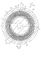
図1に示すモータ10は、永久磁石界磁型のものであり、具体的には3相巻線を有する永久磁石界磁型同期機である。つまり、モータ10は、ブラシレスモータである。この3相巻線は2系統有していてもよい。モータ10は、ハウジング20と、ハウジング20に固定される固定子30と、固定子30に対して回転する回転子40と、回転子40が固定される回転軸11と、を備える。以下、本実施形態において、軸方向とは、回転軸11の軸方向のことを示す(図において矢印Y1で示す)。径方向とは、回転軸11の径方向のことを示す(図において矢印Y2で示す)。周方向とは、回転軸11の周方向のことを示す(図において矢印Y3で示す)。
The
ハウジング20は、円筒形状に形成されており、ハウジング20内には、固定子30及び回転子40等が収容されている。ハウジング20は、円盤状の蓋部材21,22を有しており、軸方向両端におけるハウジング20の開口部は、それぞれ蓋部材21,22により閉塞されている。
The
図1において左側に配置される蓋部材21は、ハウジング20の外径と同程度の外径を有する円板状に形成されており、ネジ等を介してハウジング20に固定されている。図1において右側に配置される蓋部材22は、ハウジング20の内径と同程度の外径を有する円板状に形成されており、ハウジング20の内周面に圧入固定されている。
The
ハウジング20(より詳しくはハウジング20の蓋部材21,22)には、軸受け23,24が設けられており、この軸受け23,24により回転軸11が回転自在に支持されている。ハウジング20の内周面の軸心は、回転軸11と同軸となっている。また、図2に示すように、径方向におけるハウジング20の内周面の断面形状は、凹凸のない真円形状である。回転軸11の先端側には、角度センサ12が設けられている。角度センサ12は、磁気センサでもレゾルバでもよい。
固定子30は、ハウジング20の軸方向略中央において、ハウジング20の内周に沿って円筒状に設けられている。そして、固定子30は、回転軸11の軸心Oを中心にして、ハウジング20の内周面に固定されている。固定子30は、磁気回路の一部を構成するものであり、円環状をなし回転子40の外周側において径方向に対向して配置される固定子鉄心31(ステータコア)と、固定子鉄心31に巻装された固定子巻線32(アーマチャコイル)とを有している。
The
図2に示すように、固定子鉄心31は、円環状のバックヨーク33と、バックヨーク33から径方向内側へ突出し周方向に所定距離を隔てて配列された複数のティース34とを有し、隣り合うティース34の間にスロット35(ステータスロット)が形成されている。固定子鉄心31においてスロット35は周方向に等間隔に設けられ、そのスロット35に固定子巻線32が巻装される。本実施形態では、ティース34の数を「60」とし、スロット35の数を「60」としている。ただしその数は任意である。これらスロット35が周方向においてそれぞれU相スロット、V相スロット及びW相スロットとなっている。固定子巻線32は、当該スロット35に収容され保持されている。
As shown in FIG. 2, the
固定子鉄心31は、円環状をなす複数の薄板状の磁性体である鋼板31a(コアシート)を、固定子鉄心31の軸方向に積層して形成された一体型のものである。鋼板31aは、帯状の電磁鋼板材をプレス打ち抜きすることで形成される。また、本実施形態では、カシメ加工を行うことにより、各鋼板31aが積層状態で固定されることとなる。
The
詳しく説明すると、図2及び図3に示すように、軸方向において、各鋼板31aの一方の面には、軸方向に沿って凹部31bが複数(本実施形態では12カ所)設けられている。各凹部31bは、周方向に等間隔になるように配置されている。
More specifically, as shown in FIGS. 2 and 3, in the axial direction, one surface of each steel plate 31a is provided with a plurality of
そして、軸方向において、各鋼板31aの他方の面には、軸方向に沿って突出する凸部31cが複数(本実施形態では12カ所)設けられている。凸部31cは、周方向に等間隔になるように設けられている。各鋼板31aが積層された場合、凹部31b及び凸部31cの径方向及び周方向の位置は、同一になっている。また、軸方向における凹部31bの深さ寸法と、凸部31cの高さ寸法はほぼ同じとなっている。また、凹部31b及び凸部31cは、軸方向から見た場合、ほぼ円形に形成されている。なお、各鋼板31aの一方の面から、棒状の冶具等により軸方向に押圧力を加えて鋼板31aを塑性変形させることにより、凹部31b及び凸部31cを同時に設けることができる。
Then, in the axial direction, a plurality of
図3に示すように、凹部31b及び凸部31cは、バックヨーク33に設けられる。また、凹部31b及び凸部31cは、周方向においてティース34の根元部分の範囲内に設けられている。
As shown in FIG. 3, the
そして、鋼板31aの各凸部31cが、当該鋼板31aに固定させる鋼板31aの各凹部31bに対してそれぞれカシメ固定されることにより、各鋼板31aが積層状態で固定される。これにより、各鋼板31aは、他の鋼板31aに対して周方向及び径方向(及び軸方向)の移動が規制され、他の鋼板31aに対する位置が固定されることとなる。本実施形態において、凹部31bが固定用穴部に相当する。
Then, each
固定子巻線32は、Y結線された3相巻線により構成されている。そして、固定子巻線32は、電力(交流電力)が供給されることで磁束を発生する。固定子巻線32は、連続線を利用して設けてもよく、また、略矩形断面(平角断面)の一定太さの電気導体を略U字状に成形した導体セグメントをスロット35に挿入し、それらの端部を接続して設けてもよい。
The stator winding 32 is composed of a Y-connected three-phase winding. Then, the stator winding 32 generates magnetic flux by being supplied with electric power (AC power). The stator winding 32 may be provided by using a continuous wire, and a conductor segment obtained by forming an electric conductor having a substantially rectangular cross section (flat cross section) and having a constant thickness into a substantially U shape is inserted into the
回転子40は、磁気回路の一部を構成するものであり、周方向に1又は複数対の磁極を有し、固定子30に対して径方向に対向するように配置される。本実施形態において、回転子40は、10個の(すなわち、磁極対数が5個となる)磁極を有する。回転子40は、磁性体からなる回転子鉄心41と、回転子鉄心41に固定される永久磁石42と、を備える。具体的には、図2に示すように、回転子40は、周方向に極性が交互となるように永久磁石42を10個備えており、回転子鉄心41に軸方向に沿って設けられた収容孔に永久磁石42が埋め込まれている。
The
回転子40は、周知の構成でよく、例えば、IPM型(Interior Permanent Magnet:埋め込み磁石型)の回転子であっても、SPM型(Surface Permanent Magnet:表面磁石側)の回転子であってもよい。また、回転子40として、界磁巻線側の回転子を採用してもよい。本実施形態では、IPM型の回転子を採用している。回転子40には、回転軸11が挿通され、回転軸11を中心にして回転軸11と一体回転するように回転軸11に固定されている。
The
モータ10には、図示しない制御装置が接続されている。制御装置は、CPU、ROM、RAM及びI/O等を備えたマイクロコンピュータを主体として構成されており、CPUがROMに記憶されているプログラムを実行することにより、各種機能を実現する。なお、各種機能は、ハードウェアである電子回路によって実現されてもよく、あるいは、少なくとも一部をソフトウェア、すなわちコンピュータ上で実行される処理によって実現されてもよい。
A control device (not shown) is connected to the
制御装置が備える機能としては、例えば、外部(例えばバッテリ)からの電力を変換し、モータ10に供給して駆動力を発生させる機能を有する。また、例えば、制御装置は、角度センサ12から入力された回転角度に関する情報を利用して、モータ10の制御(電流制御など)を行う機能を備える。
As a function provided in the control device, for example, it has a function of converting electric power from an outside (for example, a battery) and supplying it to a
ところで、固定子30をハウジング20の内周面に圧入固定する場合、回り止めを適切に行うことができる程度に、ハウジング20から固定子30への径方向の応力(圧力)を高める必要がある。このため、例えば、固定する前において固定子鉄心31の外径をハウジング20の内径よりもわずかに大きくするなど、圧入代を設けてから圧入固定する必要がある。また、例えば、本実施形態に示すように、ハウジング20の内径と同程度の外径を有する蓋部材22を、ハウジング20の開口部付近にて、ハウジング20の内周面を圧入固定する。このようにすることにより、ハウジング20の開口部分において、蓋部材22から径方向外側への応力が加えられることとなり、その影響により、ハウジング20の軸方向中央側において径方向内側への応力が増加することとなる。つまり、蓋部材22よりも軸方向において内側に位置する固定子鉄心31への径方向応力を高めて、回り止めを適切に行うようにしている。
By the way, when the
しかしながら、このようにした場合、ハウジング20から固定子鉄心31への応力が大きくなりすぎ、固定子鉄心31が歪む虞がある。そして、固定子鉄心31が歪む場合、磁気損失が大きくなるなどの問題が生じることとなる。
However, in this case, the stress from the
より詳しくは、固定子鉄心31の歪みに伴い、固定子鉄心31において磁束が流れる磁路が細くなる、又は曲がることにより、磁気飽和や磁束漏れが生じ、磁気損失が大きくなる。また、応力がかかることで磁気損失が大きくなるように固定子鉄心31の材質自体が変化する。磁気損失が大きくなると、トルクの低下につながり、結果としてモータ10の小型軽量化を阻む要因となる。また、磁気損失を補うために、電流を大きくすれば、発熱が大きくなり、発熱に対処する必要が出てくる。更にいえば、固定子巻線32に通電させていないときにおける損失も大きくなるため、固定子巻線32に通電させていないときにおける損失を抑制したいEPS装置に採用しにくくなる。
More specifically, as the
そこで、固定子鉄心31の歪みを抑制すべく、固定子鉄心31の形状に対して工夫を施した。以下、詳しく説明する。
Therefore, in order to suppress the distortion of the
図2に示すように、バックヨーク33の外周には、径方向外側に開口する切欠き36が設けられており、切欠き36は、周方向においてティース34の範囲に対して重複するように設けられている。より詳しくは、図4に示すように、周方向において切欠き36の中心位置T1が、少なくても、周方向においてティース34の根元部分の範囲H1内になるように固定子鉄心31が形成されている。本実施形態において、切欠き36は、断面形状が三角形状に形成されており、頂点位置が中心位置T1となるようになっている。切欠き36の頂点位置は、切欠き36のうち、径方向において最も内側の位置である。また、切欠き36は、中心位置T1を中心として左右対称に形成されている。
As shown in FIG. 2, a
また、切欠き36の中心位置T1が、ティース34の先端の範囲H2内に位置するように設けられている。本実施形態においてティース34の先端は、図2及び図4に示すように、周方向において一方側(図2では、時計回り方向)に延びるように形成されている。この場合であっても、切欠き36の中心位置T1が、ティース34の先端の範囲H2内に位置するように設けられている。
Further, the center position T1 of the
また、本実施形態において、周方向において切欠き36の全域(切欠き36の径方向外側における幅寸法L1)が、周方向においてティース34の根元部分の範囲H1内になるように固定子鉄心31が形成されている。つまり、切欠き36の幅寸法L1≦ティース34の根元部分の範囲H1になるように、切欠き36及びティース34が設けられている。
Further, in the present embodiment, the
径方向における切欠き36の厚さ寸法A1(切欠き36の深さ寸法)は、径方向におけるバックヨーク33の厚さ寸法E1に比較して、短く形成されている。つまり、切欠き36の厚さ寸法A1<バックヨーク33の厚さ寸法E1となっている。径方向における切欠き36の厚さ寸法A1は、図4に示すように、周方向における切欠き36の端点C1,C2を結ぶ直線と、中心位置T1を通過する径方向に沿った直線との交点D1から、切欠き36の中心位置T1(頂点位置)までの距離に相当する。
The thickness dimension A1 of the
また、径方向における切欠き36の厚さ寸法A1は、径方向におけるハウジング20の厚さ寸法F1に比較して、短く形成されている。つまり、切欠き36の厚さ寸法A1<ハウジング20の厚さ寸法F1となっている。ハウジング20の厚さ寸法F1は、固定子鉄心31が圧接するハウジング20の円筒部における厚さ寸法に相当する。より望ましくは、A1/F1>0.1の関係になるように、切欠き36の厚さ寸法A1及びハウジング20の厚さ寸法F1が設計されていることが望ましい。
Further, the thickness dimension A1 of the
また、切欠き36の厚さ寸法A1は、バックヨーク33の厚さ寸法E1から切欠き36の厚さ寸法A1を減算した値が、周方向におけるティース34の根元部分の範囲H1よりも大きくなるように設けられている。より望ましくは、A1/E1>0.15の関係になるように、切欠き36の厚さ寸法A1及びバックヨーク33の厚さ寸法E1が設計されていることが望ましい。
Further, as for the thickness dimension A1 of the
また、切欠き36の厚さ寸法A1は、幅寸法L1に比較して短く形成されている。より望ましくは、A1/L1≦0.5の関係になるように、切欠き36の厚さ寸法A1及び幅寸法L1が設計されていることが望ましい。また、回転軸11の軸心Oからハウジング20の外径までの距離G1と、切欠き36の厚さ寸法A1と、がA1/G1>0.005の関係を有するように、切欠き36の厚さ寸法A1が設計されていることが望ましい。
Further, the thickness dimension A1 of the
そして、切欠き36は、軸方向において、固定子鉄心31の全域に亘って設けられている。その際、周方向における切欠き36の位置は、軸方向において、同じ位置となるように設けられている。すなわち、軸方向において、切欠き36は、軸方向に沿った直線上に設けられていることとなる。
The
また、切欠き36は、固定子鉄心31の外周において複数(12カ所)設けられている。各切欠き36は、周方向に等間隔(等角度間隔、本実施形態では30度間隔)で設けられている。ところで、本実施形態の固定子30において、スロット数は「60」であり、磁極対数は「5」である。このため、回転軸11が30度[deg]回転するごと(機械角で30度ごと)に、電気角において360度回転(1回転)することとなる。
Further, a plurality (12 places) of
したがって、電気角における360度回転(1回転)は、スロット35の数又はティース34の数でいえば、12個通過することに相当する。このため、切欠き36の数は、スロット35の数を回転子40の磁極対数で除算した数、又はその倍数にすることが望ましい。このようにすることにより、電気角において同じ角度において切欠き36に基づく磁束の歪みを生じさせることができ、回転磁界を一様にすることが可能となり、制御しやすくなるからである。また、切欠き36の数は、圧入固定する際に不都合がなければ、なるべく少ない方が望ましい。したがって、本実施形態では、前述したように、12カ所(=60/5)に切欠き36を等間隔で設けている。
Therefore, a 360-degree rotation (one rotation) at an electric angle corresponds to passing 12
また、凹部31bに対して凸部31cをカシメ固定する場合、切欠き36の近傍に凹部31bが存在すると、切欠き36へ凸部31cからの応力を逃がすように、凹部31bが変形する可能性がある。凹部31bが変形すると、凸部31cに対する凹部31bの固定力が弱くなる可能性がある。また、凹部31bを設けることにより、磁束が流れる磁路が歪む。このため、切欠き36の近傍に、凹部31bが存在すると、磁束の歪みが重畳し、磁気損失が大きくなる可能性もある。
Further, when the
そこで、切欠き36は、凹部31bに対して径方向及び周方向において重複しない位置になるように設けられている。具体的には、凹部31bが設けられているティース34に隣接するティース34のうち、予め決められた一方側(本実施形態では時計回り方向)のティース34の範囲内に切欠き36が設けられている。また、凹部31bよりも径方向外側に位置するように、切欠き36が設けられている。
Therefore, the
なお、凹部31bをバックヨーク33に設ける場合、切欠き36を設けた場合と同様に、磁束の歪みが生じる。このため、切欠き36と同様に、凹部31bの数は、スロット35の数を回転子40の磁極対数で除算した数、又はその倍数にすることが望ましい。このようにすることにより、電気角において同じ角度において凹部31bに基づく磁束の歪みを生じさせることができ、回転磁界を一様にすることが可能となり、制御しやすくなるからである。また、凹部31bの数は、カシメ固定に不都合がなければ、なるべく少ない方が望ましい。このため、本実施形態では、前述したように、12カ所(=60/5)に凹部31bを等間隔で設けている。
When the
上述したように構成したことによる有利な効果について以下に述べる。 The advantageous effects of the above configuration will be described below.
バックヨーク33の外周に、径方向外側に開口する切欠き36を設けた。これにより、ハウジング20の内周面にバックヨーク33を圧入固定しても、バックヨーク33に加えられる径方向の応力が切欠き36により逃がされ、バックヨーク33が変形することを抑制できる。
A
磁束は、磁気飽和がなければ、原則として磁性体の中を最短距離で流れる性質を有する。磁束は、ティース34から流入又は流出することから、図4において矢印Y5に示すように、バックヨーク33を流れる磁束は、ティース34に向かって円弧を描くように流入する。また、矢印Y6に示すように、ティース34から流出する磁束は、円弧を描くようにバックヨーク33へ流れ込むこととなる。また、径方向内側であるほど、磁束密度が高くなることが予想される。このため、バックヨーク33の外周のうち、ティース34が設けられている範囲H1は、ティース34が設けられていない(つまり、スロット35の)範囲H5に比較して、磁束が流れにくい範囲であるといえる。つまり、バックヨーク33の外周において、ティース34が設けられている範囲H1は、切欠き36を設けても磁束の流れに対して影響の少ない領域であるといえる。
In principle, the magnetic flux has the property of flowing in the magnetic material at the shortest distance if there is no magnetic saturation. Since the magnetic flux flows in or out of the
そこで、切欠き36を、バックヨーク33の外周のうち、周方向においてティース34の範囲H1に対して重複するように設けた。このため、切欠き36により、バックヨーク33の厚さ寸法が一部分だけ短くなることを抑制できる。すなわち、磁路の幅を確保して、切欠き36がバックヨーク33を通過する磁束の妨げになりにくく、切欠き36による磁束の歪みを抑制することができる。したがって、磁気飽和や磁束の流れを歪むことを抑制することができる。そして、磁気損失を抑制し、モータ10の小型化軽量化を実現することができる。また、電流量を減らして、発熱量を抑制することができる。また、トルクリプルを抑制できる。
Therefore, the
図4に示すように、磁束はティース34から流入又は流出するため、周方向におけるティース34の幅(範囲H1)に相当する磁路を確保できれば、ティース34から流入又は流出する磁束を、磁気飽和を生じさせることなく通過させることができる。そこで、径方向におけるバックヨーク33の厚さ寸法E1から径方向における切欠き36の厚さ寸法A1を減算した値が、ティース34の周方向における幅(範囲H1)よりも大きくなるように、切欠き36を設けた。これにより、バックヨーク33においてティース34からの磁束により磁気飽和が発生することを抑制できる。それに伴い、磁束の流れが歪むことを抑制できる。
As shown in FIG. 4, since the magnetic flux flows in or out from the
電気角において360度回転するごとに(つまり、交流電流が1サイクル流れるごとに)、スロット35の数を磁極対数で除算した数のスロット35を通過することとなる。そして、切欠き36に基づく磁束の歪みが発生した場合であっても、切欠き36に基づく磁束の歪みが電気角において同じ角度で生じるならば、電流制御がしやすくなる。例えば、磁束の歪みが電気角において同じ角度で生じる場合、磁束の歪みに基づく磁界の変化を抑制するような電流制御を行いやすくなる。また、一定周期でトルクリプルが生じる場合、不定期にトルクリプルが生じる場合と比較して、違和感を与え難い。そこで、切欠き36の数を、スロット35の数を回転子40の磁極対数で除算した数になるようにし、かつ、各切欠き36を、バックヨーク33において、周方向に等間隔に配置した。これにより、制御しやすくなり、また、トルクリプルを抑制できる。
Every time it rotates 360 degrees in the electrical angle (that is, every time an alternating current flows for one cycle), it passes through the number of
鋼板31aに凹部31bを設けた場合、凹部31bに基づいて磁束が歪むこととなる。このため、切欠き36が、周方向又は径方向において凹部31bに対して重複すると、切欠き36による磁束の歪みと凹部31bによる磁束の歪みが重畳し、磁束の歪みが大きくなり、場合によっては磁気飽和が生じる場合がある。そこで、切欠き36が、周方向及び径方向において凹部31bに対して重複しないようにして、切欠き36による磁束の歪みと凹部31bによる磁束の歪みが重畳することを防止した。これにより、磁束の歪みが大きくなることや、磁気飽和や磁束漏れを抑制することができる。
When the
また、周方向において切欠き36が設けられたティース34に隣接するティース34の範囲(隣接するティースの範囲H1)に凹部31b及び凸部31cを設けた。これにより、カシメ固定される凹部31b及び凸部31cに対して、切欠き36の距離を近づけることができ、凹部31bに対して凸部31cをカシメ固定する場合において、カシメ固定による応力が切欠き36へ逃げて凹部31bが変形することを抑制できる。このため、カシメ固定を確実に行うことができる。
Further, the
ハウジング20には、固定子30の軸方向外側において、ハウジング20の内周面に圧接する円板状の固定部材としての蓋部材22が設けられている。これにより、固定子鉄心31に対して径方向への応力を高めて、より圧接させ、周方向における回り止めを確実に行うことができる。
The
切欠き36は、径方向に沿った中心線を中心に、周方向に左右対称に設けられている。これにより、ハウジング20からの応力を均等に逃すことができ、応力が集中してバックヨーク33が歪むことを抑制できる。また、切欠き36による磁束の歪みを均等に発生させることができ、制御しやすくなる。
The
径方向における切欠き36の断面形状を、三角形状にした。多角形の頂点部は応力が集中しやすいため、三角形状としたことで、多角形状にする場合と比較して、応力を均等に逃すことができ、応力が集中してバックヨーク33が歪むことを抑制できる。また、切欠き36による磁束の歪みを均等に発生させることができ、制御しやすくなる。
The cross-sectional shape of the
ハウジング20の内周面の横断面形状を、凹凸のない真円形状にした。これにより、固定子鉄心31からの応力により、ハウジング20が歪むことを抑制できる。また、ハウジング20を製造しやすくなる。
The cross-sectional shape of the inner peripheral surface of the
(他の実施形態)
なお、本発明は上記実施形態に限定されるものではなく、本発明の要旨の範囲内において種々の変形実施が可能である。
(Other embodiments)
The present invention is not limited to the above embodiment, and various modifications can be made within the scope of the gist of the present invention.
・上記実施形態において、スロット35の数、固定子巻線32の形状、巻き数、巻き方などを任意に変更してもよい。また、磁極対数を任意に変更してもよい。また、切欠き36の数や配置を任意に変更してもよい。また、ティース34の範囲内に存在するならば、切欠き36の径方向における厚さ寸法、周方向における幅寸法、形状等を任意に変更してもよい。また、凹部31b及び凸部31cの形状、配置、大きさ、数を任意に変更してもよい。また、凹部31b及び凸部31cを設けなくてもよい。例えば、接着により固定してもよい。また、回転子40を積層することにより形成しなくてもよい。
-In the above embodiment, the number of
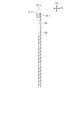
・上記実施形態において、ティース34(及びスロット35)が、軸方向において、周方向の位置が段階的に又は徐々(連続的)にずれるスキュー構造を有していてもよい。図5において徐々にずれるスキュー構造を例示する。なお、図5では、図面の都合上、ティース34及びスロット35の数を12個としている。この場合において、切欠き36は、軸方向においていずれの位置においても、ティース34の範囲内に存在するように設けられている。
-In the above embodiment, the teeth 34 (and the slot 35) may have a skew structure in which the position in the circumferential direction is shifted stepwise or gradually (continuously) in the axial direction. FIG. 5 illustrates a skew structure that gradually shifts. In FIG. 5, for convenience of drawing, the number of
より詳しくは、少なくても切欠き36の中心位置T1が、軸方向においていずれの位置においても、ティース34の根元部分の範囲H1内に存在するようになっている。なお、図5では、切欠き36の中心位置T1(頂点位置)を破線で示す。より望ましくは、切欠き36の中心位置T1が、軸方向においていずれの位置においても、ティース34の先端部分の範囲H2内に存在することが望ましい。さらに、より好ましくは、周方向における切欠き36の全域が、軸方向においていずれの位置においても、ティース34の根元部分の範囲H1内であって、ティース34の先端部分の範囲H2内に存在することが好ましい。
More specifically, at least the central position T1 of the
これにより、軸方向においていずれの位置においても、バックヨーク33の径方向における厚さを確保し、磁束が流れる磁路を確保することができる。つまり、磁気損失を抑制することができる。
As a result, the thickness of the
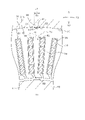
なお、図6に段階的にずれるスキュー構造を図示する。この場合も図5の場合と同様に、切欠き36は、軸方向においていずれの位置においても、ティース34の範囲内に存在するように設けられていることが望ましい。
Note that FIG. 6 shows a skew structure that shifts stepwise. In this case as well, as in the case of FIG. 5, it is desirable that the
・上記実施形態において、径方向における切欠き36の断面形状を、円弧状にしてもよい。これにより、応力を均等に逃すことができ、応力が集中してバックヨーク33が歪むことを抑制できる。また、切欠き36による磁束の歪みを均等に発生させることができ、制御しやすい。
-In the above embodiment, the cross-sectional shape of the
・上記実施形態において、各鋼板31aには、カシメ固定を行うための凹部31b及び凸部31cを設けたが、凹部31b及び凸部31cの代わりに軸方向に沿って貫通孔を設けてもよい。そして、各鋼板31aが積層状態にした場合において、当該貫通孔に軸方向に沿った棒状の留め具としてのリベットを挿入し、軸方向両端においてリベットによるカシメ固定を行ってもよい。この場合、貫通孔が固定用穴部に相当する。貫通孔を設けた場合も、凹部31bと同様に磁束の歪みが生じる。このため、切欠き36を、周方向及び径方向において貫通孔に重複しないように設けることが望ましい。
-In the above embodiment, each steel plate 31a is provided with a
・上記実施形態におけるモータ10は、車両に搭載される発電機、電動機、あるいはそれら両者の機能を発揮し得るものとして実用化できる。また、車両搭載以外の用途にて、上記構成のモータ10を用いることも可能である。
-The
・上記実施形態において、ハウジング20の内周面に、切欠き36に対して周方向に係合する突起部を設けてもよい。また、蓋部材22は、蓋部材21と同様に、ハウジング20の外径と同じ外径にして、ネジ止めなどによりハウジング20の開口部に固定してもよい。
-In the above embodiment, a protrusion that engages with the
10…モータ、20…ハウジング、30…固定子、31…固定子鉄心、33…バックヨーク、34…ティース、36…切欠き、40…回転子。 10 ... motor, 20 ... housing, 30 ... stator, 31 ... stator core, 33 ... back yoke, 34 ... teeth, 36 ... notch, 40 ... rotor.
Claims (9)
前記固定子鉄心は、前記ハウジングの内周面に固定される円環状のバックヨーク(33)と、前記バックヨークの内周から径方向に沿って設けられたティース(34)を備え、
前記バックヨークの外周には、径方向外側に開口する切欠きが設けられており、前記切欠きは、前記周方向において前記ティースの範囲に対して重複するように設けられており、
前記ティースは、軸方向において、周方向の位置が段階的に又は連続的にずれるスキュー構造を有しており、
前記切欠きは、軸方向に沿った直線上に形成されているとともに、軸方向においていずれの位置においても、前記ティースの範囲内に存在する、回転電機。 A stator (30) having an annular stator core (31) and a rotor (30) having one or more pairs of magnetic poles in the circumferential direction and arranged so as to face the stator in the radial direction. In the rotary electric machine (10) including the 40) and the cylindrical housing (20) in which the stator core is fixed to the inner peripheral surface.
The stator core includes an annular back yoke (33) fixed to the inner peripheral surface of the housing and teeth (34) provided along the radial direction from the inner circumference of the back yoke.
A notch that opens radially outward is provided on the outer periphery of the back yoke, and the notch is provided so as to overlap the range of the teeth in the circumferential direction .
The teeth have a skew structure in which the positions in the circumferential direction are shifted stepwise or continuously in the axial direction.
A rotary electric machine in which the notch is formed on a straight line along the axial direction and exists within the range of the teeth at any position in the axial direction .
前記固定子鉄心の前記ティースの間には、固定子巻線が巻装されるスロット(35)が形成されており、
前記切欠きは、周方向に等間隔に配置されており、
前記切欠きの数は、前記スロットの数を前記回転子の磁極対数で除算した数、又はその倍数である請求項1又は2に記載の回転電機。 A plurality of the teeth are provided in the circumferential direction.
A slot (35) around which the stator winding is wound is formed between the teeth of the stator core.
The notches are arranged at equal intervals in the circumferential direction.
The rotary electric machine according to claim 1 or 2, wherein the number of notches is a number obtained by dividing the number of slots by the number of magnetic pole pairs of the rotor, or a multiple thereof.
前記コアシートには、軸方向に沿って固定用穴部(31b)が設けられており、前記固定用穴部に、他の前記コアシートに設けられた凸部(31c)がカシメ固定されることにより、前記コアシート間の固定が行われるものであり、
前記固定用穴部は、周方向に所定間隔ごとに複数設けられるとともに、前記周方向において前記ティースの範囲に対して重複するように設けられ、
前記切欠きは、周方向及び径方向において前記固定用穴部に対して重複しない位置に設けられており、
前記切欠きは、周方向において、隣り合う前記固定用穴部の中間位置よりも、前記固定用穴部に近い位置に配置されている、請求項1~3のうちいずれか1項に記載の回転電機。 The stator core is formed by laminating a plurality of plate-shaped core sheets (31a) in the axial direction.
The core sheet is provided with a fixing hole (31b) along the axial direction, and another convex portion (31c ) provided on the core sheet is caulked and fixed to the fixing hole. As a result, the core sheets are fixed to each other.
A plurality of the fixing holes are provided at predetermined intervals in the circumferential direction, and are provided so as to overlap the range of the teeth in the circumferential direction.
The notch is provided at a position that does not overlap with the fixing hole in the circumferential direction and the radial direction .
The invention according to any one of claims 1 to 3 , wherein the notch is arranged at a position closer to the fixing hole than an intermediate position of the adjacent fixing holes in the circumferential direction. Rotating electric machine.
Priority Applications (3)
| Application Number | Priority Date | Filing Date | Title |
|---|---|---|---|
| JP2018182226A JP7103122B2 (en) | 2018-09-27 | 2018-09-27 | Rotating electric machine |
| CN201910911049.5A CN110957820A (en) | 2018-09-27 | 2019-09-25 | Rotating electrical machine |
| US16/582,247 US11374443B2 (en) | 2018-09-27 | 2019-09-25 | Rotary electric machine |
Applications Claiming Priority (1)
| Application Number | Priority Date | Filing Date | Title |
|---|---|---|---|
| JP2018182226A JP7103122B2 (en) | 2018-09-27 | 2018-09-27 | Rotating electric machine |
Publications (2)
| Publication Number | Publication Date |
|---|---|
| JP2020054135A JP2020054135A (en) | 2020-04-02 |
| JP7103122B2 true JP7103122B2 (en) | 2022-07-20 |
Family
ID=69945085
Family Applications (1)
| Application Number | Title | Priority Date | Filing Date |
|---|---|---|---|
| JP2018182226A Active JP7103122B2 (en) | 2018-09-27 | 2018-09-27 | Rotating electric machine |
Country Status (3)
| Country | Link |
|---|---|
| US (1) | US11374443B2 (en) |
| JP (1) | JP7103122B2 (en) |
| CN (1) | CN110957820A (en) |
Families Citing this family (2)
| Publication number | Priority date | Publication date | Assignee | Title |
|---|---|---|---|---|
| CN111384790A (en) * | 2018-12-28 | 2020-07-07 | 福特全球技术公司 | Stator for motor and motor |
| JP2022055707A (en) * | 2020-09-29 | 2022-04-08 | 本田技研工業株式会社 | Rotary electric machine |
Citations (6)
| Publication number | Priority date | Publication date | Assignee | Title |
|---|---|---|---|---|
| DE19653838A1 (en) | 1996-12-21 | 1998-06-25 | Rainer Born | Stator plate for electrical machine with annular wound coils in slots |
| JP2000350390A (en) | 1999-06-04 | 2000-12-15 | Daikin Ind Ltd | Switched reluctance motor |
| JP2001258225A (en) | 2000-03-09 | 2001-09-21 | Toyoda Mach Works Ltd | Motor |
| JP2003032939A (en) | 2001-07-11 | 2003-01-31 | Matsushita Electric Ind Co Ltd | Electric motor |
| JP2016086579A (en) | 2014-10-28 | 2016-05-19 | パナソニックIpマネジメント株式会社 | Brushless motor and electric power tool |
| JP2016111731A (en) | 2014-12-02 | 2016-06-20 | 多摩川精機株式会社 | Resolver |
Family Cites Families (23)
| Publication number | Priority date | Publication date | Assignee | Title |
|---|---|---|---|---|
| JPH02179246A (en) | 1988-12-28 | 1990-07-12 | Fanuc Ltd | Stator construction of built-in motor |
| JPH0583891A (en) * | 1991-09-18 | 1993-04-02 | Sony Corp | Iron core motor |
| JP2585446Y2 (en) * | 1992-05-25 | 1998-11-18 | 自動車電機工業株式会社 | Motor case opening end cover fixing structure |
| JPH0731086A (en) * | 1993-07-02 | 1995-01-31 | Toyota Motor Corp | Stator structure for three-phase synchronous motor and stator |
| JP2003169431A (en) * | 2001-11-29 | 2003-06-13 | Hitachi Ltd | Motor |
| JP2008061407A (en) * | 2006-08-31 | 2008-03-13 | Jtekt Corp | Electric motor |
| JP5171224B2 (en) * | 2007-11-22 | 2013-03-27 | 三菱電機株式会社 | Rotating electric machine |
| JP5389559B2 (en) * | 2009-07-23 | 2014-01-15 | 愛三工業株式会社 | Rotating motor stator and fuel pump |
| EP2579428A4 (en) * | 2010-06-02 | 2015-12-23 | Aisin Seiki | Electrical rotary machine |
| JP2012253834A (en) | 2011-05-31 | 2012-12-20 | Hitachi Koki Co Ltd | Motor for electric machine and air compressor |
| US9502931B2 (en) * | 2012-03-23 | 2016-11-22 | Asmo Co., Ltd. | Brushless motor |
| US9806566B2 (en) * | 2012-08-30 | 2017-10-31 | Asmo Co., Ltd. | Brushless motor, stator, stator manufacturing method and brushless motor manufacturing method |
| JP6096441B2 (en) * | 2012-09-05 | 2017-03-15 | 東芝メディカルシステムズ株式会社 | Medical image processing apparatus, medical image processing method, and medical image processing program |
| JP5850259B2 (en) * | 2012-11-28 | 2016-02-03 | 株式会社デンソー | Rotating electric machine |
| JP6075539B2 (en) | 2013-01-15 | 2017-02-08 | 日本電産株式会社 | motor |
| JP2014153069A (en) | 2013-02-05 | 2014-08-25 | Jtekt Corp | Resolver and rolling bearing device with resolver |
| US9800102B2 (en) * | 2013-03-06 | 2017-10-24 | Asmo Co., Ltd. | Dual rotor core motor with reduced flux leakage |
| JP2015139265A (en) | 2014-01-21 | 2015-07-30 | アイシン・エィ・ダブリュ株式会社 | stator core |
| EP3197019A4 (en) * | 2014-09-05 | 2018-06-06 | Hitachi Automotive Systems, Ltd. | Stator for rotary electric machine and rotary electric machine equipped with same |
| US20170331336A1 (en) * | 2014-12-02 | 2017-11-16 | Mitsubishi Electric Corporation | Stator core for rotating electrical machine, rotating electrical machine, and method of manufacturing rotating electrical machine |
| WO2017002873A1 (en) * | 2015-06-29 | 2017-01-05 | 株式会社ミツバ | Brushless motor |
| CN106549512B (en) * | 2015-09-16 | 2019-06-14 | 雅马哈发动机株式会社 | Rotating electric machine |
| JP6595443B2 (en) * | 2016-12-01 | 2019-10-23 | トヨタ自動車株式会社 | Rotating electric machine |
-
2018
- 2018-09-27 JP JP2018182226A patent/JP7103122B2/en active Active
-
2019
- 2019-09-25 US US16/582,247 patent/US11374443B2/en active Active
- 2019-09-25 CN CN201910911049.5A patent/CN110957820A/en active Pending
Patent Citations (6)
| Publication number | Priority date | Publication date | Assignee | Title |
|---|---|---|---|---|
| DE19653838A1 (en) | 1996-12-21 | 1998-06-25 | Rainer Born | Stator plate for electrical machine with annular wound coils in slots |
| JP2000350390A (en) | 1999-06-04 | 2000-12-15 | Daikin Ind Ltd | Switched reluctance motor |
| JP2001258225A (en) | 2000-03-09 | 2001-09-21 | Toyoda Mach Works Ltd | Motor |
| JP2003032939A (en) | 2001-07-11 | 2003-01-31 | Matsushita Electric Ind Co Ltd | Electric motor |
| JP2016086579A (en) | 2014-10-28 | 2016-05-19 | パナソニックIpマネジメント株式会社 | Brushless motor and electric power tool |
| JP2016111731A (en) | 2014-12-02 | 2016-06-20 | 多摩川精機株式会社 | Resolver |
Also Published As
| Publication number | Publication date |
|---|---|
| US11374443B2 (en) | 2022-06-28 |
| JP2020054135A (en) | 2020-04-02 |
| US20200106311A1 (en) | 2020-04-02 |
| CN110957820A (en) | 2020-04-03 |
Similar Documents
| Publication | Publication Date | Title |
|---|---|---|
| JP4640422B2 (en) | Landel rotor type motor | |
| EP3200318A1 (en) | Brushless motor | |
| US9143014B2 (en) | Rotor, dynamo-electric machine having the rotor and rotor manufacturing method | |
| US20110018384A1 (en) | Motor | |
| JP5776652B2 (en) | Rotating electrical machine rotor | |
| JP2006333657A (en) | Motor | |
| JP6380310B2 (en) | Rotating electric machine stator | |
| JP6864595B2 (en) | Rotor core, rotor, rotary electric machine, electric auxiliary equipment system for automobiles | |
| JP2013230047A (en) | Rotor for motor, and motor | |
| JP2014045630A (en) | Rotary electric machine | |
| JP3928297B2 (en) | Electric motor and manufacturing method thereof | |
| JP7103122B2 (en) | Rotating electric machine | |
| JP2013099038A (en) | Rotor for electric motor and brushless motor | |
| JP2013102597A (en) | Rotor for electric motor and brushless motor | |
| WO2007123057A1 (en) | Motor | |
| JP2008312348A (en) | Electric motor | |
| JP6869158B2 (en) | Rotor core, rotor, rotary electric machine, electric auxiliary equipment system for automobiles | |
| JP2004222356A (en) | Rotating electric equipment | |
| JP6695241B2 (en) | Brushless motor | |
| JP2008306796A (en) | Rotary electric machine | |
| JP2004336999A (en) | Permanent magnet motor | |
| JP2019047630A (en) | Rotary electric machine | |
| JP4396142B2 (en) | Permanent magnet rotating electric machine | |
| JP5256007B2 (en) | Armature and axial gap type rotating electric machine | |
| CN109997290B (en) | Synchronous reluctance type rotating electric machine |
Legal Events
| Date | Code | Title | Description |
|---|---|---|---|
| A621 | Written request for application examination |
Free format text: JAPANESE INTERMEDIATE CODE: A621 Effective date: 20210413 |
|
| A977 | Report on retrieval |
Free format text: JAPANESE INTERMEDIATE CODE: A971007 Effective date: 20220316 |
|
| A131 | Notification of reasons for refusal |
Free format text: JAPANESE INTERMEDIATE CODE: A131 Effective date: 20220322 |
|
| A521 | Request for written amendment filed |
Free format text: JAPANESE INTERMEDIATE CODE: A523 Effective date: 20220520 |
|
| TRDD | Decision of grant or rejection written | ||
| A01 | Written decision to grant a patent or to grant a registration (utility model) |
Free format text: JAPANESE INTERMEDIATE CODE: A01 Effective date: 20220607 |
|
| A61 | First payment of annual fees (during grant procedure) |
Free format text: JAPANESE INTERMEDIATE CODE: A61 Effective date: 20220620 |
|
| R151 | Written notification of patent or utility model registration |
Ref document number: 7103122 Country of ref document: JP Free format text: JAPANESE INTERMEDIATE CODE: R151 |