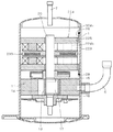
JP5040407B2 - Axial gap type motor and compressor - Google Patents
Axial gap type motor and compressor Download PDFInfo
- Publication number
- JP5040407B2 JP5040407B2 JP2007103774A JP2007103774A JP5040407B2 JP 5040407 B2 JP5040407 B2 JP 5040407B2 JP 2007103774 A JP2007103774 A JP 2007103774A JP 2007103774 A JP2007103774 A JP 2007103774A JP 5040407 B2 JP5040407 B2 JP 5040407B2
- Authority
- JP
- Japan
- Prior art keywords
- yoke
- type motor
- axial gap
- gap type
- axial
- Prior art date
- Legal status (The legal status is an assumption and is not a legal conclusion. Google has not performed a legal analysis and makes no representation as to the accuracy of the status listed.)
- Expired - Fee Related
Links
Images
Landscapes
- Compressor (AREA)
- Iron Core Of Rotating Electric Machines (AREA)
- Permanent Magnet Type Synchronous Machine (AREA)
Description
この発明は、アキシャルギャップ型モータ及び圧縮機に関する。 The present invention relates to an axial gap type motor and a compressor.
従来、圧縮機やファンに用いられるモータは、ラジアルギャップ型が主体であった。このラジアルギャップ型モータでは、ステータの外周をケーシングの内周に焼きばめしたとしても、軸方向に長いステータの全周が焼きばめされるため、ステータの内周面の変形は少なく、エアギャップの精度への影響は僅少であった。 Conventionally, motors used for compressors and fans have been mainly radial gap types. In this radial gap type motor, even if the outer periphery of the stator is shrink-fitted to the inner periphery of the casing, the entire circumference of the stator that is long in the axial direction is shrink-fitted. The impact on gap accuracy was negligible.
このようなラジアルギャップ型モータに対して、磁石面積を大きく取れ、小型化が可能であり、整列巻およびコイルの小型化により効率が向上するアキシャルギャップ型モータが近年注目されている(例えば、特開2000−253635号公報(特許文献1)参照)。 In recent years, axial gap motors that have a large magnet area and can be miniaturized and whose efficiency is improved by downsizing windings and coils have attracted attention in recent years. No. 2000-253635 (Patent Document 1)).
上記アキシャルギャップ型モータでは、ステータの外周をケーシングの内周に焼きばめするとき、軸方向に短い形状となることもあり、面内変形のみならず、軸方向も含めた変形を生じる場合がある。上記アキシャルギャップ型モータは、軸方向にエアギャップを有するため、ごくわずかな変形であってもエアギャップ精度を大幅に悪化させるという問題がある。 In the axial gap type motor described above, when the outer periphery of the stator is shrink-fitted to the inner periphery of the casing, the axial direction may be short, and not only in-plane deformation but also deformation including the axial direction may occur. is there. Since the axial gap type motor has an air gap in the axial direction, there is a problem that the accuracy of the air gap is greatly deteriorated even with a slight deformation.
そこで、この発明の課題は、焼きばめ等によるヨークの変形を防止でき、エアギャップ精度を向上できるアキシャルギャップ型モータ及び圧縮機を提供することにある。 SUMMARY OF THE INVENTION An object of the present invention is to provide an axial gap type motor and a compressor that can prevent deformation of the yoke due to shrink fitting or the like and improve air gap accuracy.
上記課題を解決するため、この発明のアキシャルギャップ型モータの第1の態様は、所定の回転軸に対して略直交する略環状の磁性体からなるヨークと、上記ヨークの少なくとも一方の端面側に軸方向に起立するように、周方向に設けられた磁性体からなるティースと、上記ティースに巻回されたコイルとを有するステータと、上記ステータの上記ティースの先端に所定のエアギャップを隔てて対向すると共に、上記所定の回転軸を中心に回転するロータと、上記ステータと上記ロータとを収納するケーシングとを備え、上記ステータの上記ヨークの外周が、上記ケーシングの内周に焼きばめまたは圧入により固定され、上記ヨークの外周側かつ少なくとも上記ティースよりも半径方向外側で上記ヨークを軸方向に貫通する複数の孔を設け、前記孔と前記コイルの一部とが前記軸方向で互いに対向することを特徴とする。
In order to solve the above problems, a first aspect of an axial gap type motor according to the present invention includes a yoke made of a substantially annular magnetic body substantially orthogonal to a predetermined rotation axis, and at least one end face side of the yoke. A stator having teeth made of a magnetic material provided in the circumferential direction so as to stand up in the axial direction and a coil wound around the teeth, and a predetermined air gap is provided at the tip of the teeth of the stator. A rotor that opposes and rotates about the predetermined rotation axis, and a casing that houses the stator and the rotor, and an outer periphery of the yoke of the stator is shrink-fitted or fitted to an inner periphery of the casing is fixed by press-fitting, a plurality of holes through the yoke in the axial direction is provided radially outward from the outer peripheral side and at least the tooth of the yoke, A portion of the coil and Kiana characterized in that the facing each other in the axial direction.
また、第2の態様のアキシャルギャップ型モータでは、上記複数の孔は、3以上であって、周方向にかつ略等間隔に配置されている。 In the axial gap motor of the second aspect, the plurality of holes are three or more, and are arranged in the circumferential direction and at substantially equal intervals.
また、第3の態様のアキシャルギャップ型モータでは、互いに隣接する上記孔間の連結部が、上記ティース間の領域の半径方向外側にある。 Moreover, in the axial gap type motor of the third aspect, the connecting portion between the holes adjacent to each other is located radially outside the region between the teeth.
また、第4の態様のアキシャルギャップ型モータでは、上記ヨークの外周部に、上記ケーシングの内周に接触しないコアカット部が設けられ、上記複数の孔は、上記コアカット部および上記コアカット部近傍を除く領域に設けられている。 Further, in the axial gap type motor of the fourth aspect, a core cut portion that does not contact the inner periphery of the casing is provided on the outer peripheral portion of the yoke, and the plurality of holes include the core cut portion and the core cut portion. It is provided in the area excluding the vicinity.
また、第5の態様のアキシャルギャップ型モータでは、互いに隣接する上記孔間の最小間隔は、上記孔が設けられた部分の上記ヨークの厚さよりも小さい。 In the axial gap type motor of the fifth aspect, the minimum interval between the adjacent holes is smaller than the thickness of the yoke in the portion where the holes are provided.
また、第6の態様のアキシャルギャップ型モータでは、上記複数の孔と上記コアカット部との間の最小間隔は、上記孔が設けられた部分の上記ヨークの厚さよりも小さい。 In the axial gap type motor of the sixth aspect, the minimum distance between the plurality of holes and the core cut portion is smaller than the thickness of the yoke in the portion where the holes are provided.
また、第7の態様のアキシャルギャップ型モータでは、上記複数の孔の領域を軸方向に投影した部分には、少なくとも上記コイルの一部が重なる。 In the axial gap type motor according to the seventh aspect, at least a part of the coil overlaps a portion where the plurality of hole regions are projected in the axial direction.
また、第8の態様のアキシャルギャップ型モータでは、軸流ファンを駆動するアキシャルギャップ型モータであって、上記軸流ファンの風通路に、上記複数の孔を配置した。 Moreover, the axial gap type motor of the eighth aspect is an axial gap type motor for driving an axial fan, and the plurality of holes are arranged in the air passage of the axial fan.
また、第9の態様のアキシャルギャップ型モータでは、上記ケーシングに設けられた吸入口から冷媒を吸入して、上記ケーシングに設けられた吐出口から上記冷媒を吐出する圧縮機構部を駆動するアキシャルギャップ型モータであって、上記ステータは、上記吸入口から上記吐出口までの間に配置されている。 In the axial gap type motor of the ninth aspect, the axial gap that drives the compression mechanism that sucks the refrigerant from the suction port provided in the casing and discharges the refrigerant from the discharge port provided in the casing. The stator is arranged between the suction port and the discharge port.
また、第10の態様のアキシャルギャップ型モータでは、上記ヨークのうち、少なくとも上記ケーシングの内周に焼きばめまたは圧入される部分と上記複数の孔の周辺部分は、薄板が軸方向に積層された積層鋼板により一体に形成されている。 In the axial gap motor of the tenth aspect, at least a portion of the yoke that is shrink-fitted or press-fitted into the inner periphery of the casing and a peripheral portion of the plurality of holes are laminated in the axial direction. The laminated steel plate is integrally formed.
また、第11の態様のアキシャルギャップ型モータでは、上記ティースは、圧粉磁心からなり、上記ヨーク内に軸方向に所定の深さ埋め込まれているか、または、上記ヨーク内に軸方向に貫通するように埋め込まれている。 In the axial gap type motor of the eleventh aspect, the teeth are made of a dust core and are embedded in the yoke in a predetermined depth in the axial direction, or penetrate in the yoke in the axial direction. Is embedded as such.
また、第12の態様のアキシャルギャップ型モータでは、上記ステータの上記ヨークの外周のうち、上記複数の孔が周方向に延在する範囲内で、上記ケーシングの内周に溶接により固定されている。 In the axial gap motor of the twelfth aspect, the outer periphery of the yoke of the stator is fixed to the inner periphery of the casing by welding within a range in which the plurality of holes extend in the circumferential direction. .
また、第13の態様のアキシャルギャップ型モータでは、上記孔は、少なくとも上記ティースの間の径方向外側に延長した部分に設けられている。 In the axial gap type motor of the thirteenth aspect, the hole is provided at least in a portion extending radially outward between the teeth.
また、第14の態様のアキシャルギャップ型モータでは、上記孔は、上記コイルを避けて貫通する部分を有する。 Moreover, in the axial gap type motor according to the fourteenth aspect, the hole has a portion penetrating to avoid the coil.
また、第15の態様のアキシャルギャップ型モータでは、上記孔は、周方向に隣接する上記コイルの間でも上記ヨークを軸方向に貫通する。 In the axial gap type motor according to the fifteenth aspect, the hole penetrates the yoke in the axial direction even between the coils adjacent in the circumferential direction.
また、第16の態様のアキシャルギャップ型モータでは、上記ヨークは、上記溶接が施された箇所と上記孔との間において、軸方向厚みに比べ、径方向厚みが小さい。 In the axial gap type motor according to the sixteenth aspect, the yoke has a smaller radial thickness than the axial thickness between the welded portion and the hole.
また、第17の態様のアキシャルギャップ型モータでは、上記孔の外周側で、上記ヨークの外周端部から軸方向に突出した溶接部を有し、上記溶接部において上記ヨークと上記ケーシングとが溶接される。 In the axial gap type motor of the seventeenth aspect, the outer peripheral side of the hole has a weld portion protruding in the axial direction from the outer peripheral end portion of the yoke, and the yoke and the casing are welded at the weld portion. Is done.
また、第18の態様のアキシャルギャップ型モータでは、上記ヨークは、軸方向に積層された鋼板からなる。 In the axial gap motor of the eighteenth aspect, the yoke is made of steel plates laminated in the axial direction.
また、第19の態様のアキシャルギャップ型モータでは、上記ヨークは、圧粉鉄心からなる。 In the axial gap type motor according to the nineteenth aspect, the yoke is made of a dust core.
また、第20の態様のアキシャルギャップ型モータでは、上記ヨークは、上記ケーシングに圧入または焼きばめもされている。 In the axial gap type motor according to the twentieth aspect, the yoke is press-fitted or shrink-fitted into the casing.
また、第21の態様のアキシャルギャップ型モータでは、上記溶接が施された箇所を除く、上記ヨークの外周端部が上記ケーシングと圧入または焼きばめされている。 In the axial gap type motor according to the twenty-first aspect, the outer peripheral end of the yoke is press-fitted or shrink-fitted with the casing except for the welded portion.
また、上記課題を解決するため、この発明の圧縮機は、上記の何れかのアキシャルギャップ型モータを搭載したことを特徴とする。 In order to solve the above problems, a compressor according to the present invention includes any one of the axial gap motors described above.
例えば、この圧縮機では、冷媒がCO2である。 For example, in the compressor, the refrigerant is CO 2.
第1の態様のアキシャルギャップ型モータによれば、上記ヨークの外周側かつティースの半径方向外側に、ヨークを軸方向に貫通する複数の孔を設けたことによって、焼きばめ等による歪が緩和されて、ヨークの変形が防止されるため、エアギャップ精度が向上する。また、焼きばめによる特性劣化が、複数の孔により緩和されるため、ヨークの磁路に影響を与えない。さらには、ティースよりも半径方向外側のヨークの領域は、通常磁路として積極的に使わないため、孔を設けても、磁路を阻害することがない。さらには、ヨークの軸長は通常短いため、孔の垂直度も良好であり、精度良く孔を設けることも可能であり、ラジアルギャップ型モータと比べて孔による悪影響を排除でき、性能を向上できる。 According to the axial gap type motor of the first aspect, by providing a plurality of holes penetrating the yoke in the axial direction on the outer peripheral side of the yoke and radially outside the teeth, distortion due to shrink fitting or the like is alleviated. As a result, the deformation of the yoke is prevented, so that the air gap accuracy is improved. In addition, the characteristic deterioration due to shrink fitting is alleviated by the plurality of holes, so that the magnetic path of the yoke is not affected. Further, since the yoke area radially outside the teeth is not actively used as a normal magnetic path, even if a hole is provided, the magnetic path is not obstructed. Furthermore, since the axial length of the yoke is usually short, the verticality of the hole is also good, and it is possible to provide the hole with high precision, and the adverse effects of the hole can be eliminated and the performance can be improved compared to a radial gap type motor. .
第2の態様のアキシャルギャップ型モータによれば、3以上の孔を周方向にかつ略等間隔に配置することによって、焼きばめ時または圧入時の応力を全周にわたって均一に吸収でき、エアギャップ部の平面度を向上できる。また、孔の数は最低3あれば、焼きばめ時または圧入時の応力を安定して緩和する。 According to the axial gap type motor of the second aspect, by arranging three or more holes in the circumferential direction and at substantially equal intervals, the stress at the time of shrink fitting or press fitting can be uniformly absorbed over the entire circumference, and the air The flatness of the gap portion can be improved. If the number of holes is at least 3, the stress at the time of shrink fitting or press fitting is stably relieved.
第3の態様のアキシャルギャップ型モータによれば、上記ティース間の領域の半径方向外側にある上記孔間の連結部によって、ヨークの外周をケーシングの内周に焼きばめ(または圧入)するときの応力に対してヨークの剛性を保ちつつ、ヨークが傾かないようにできる。また、上記連結部がティース間の領域の半径方向外側にあるので、磁気特性に対する影響も少ない。 According to the axial gap type motor of the third aspect, when the outer periphery of the yoke is shrink-fitted (or press-fitted) into the inner periphery of the casing by the connecting portion between the holes on the radially outer side of the region between the teeth. It is possible to prevent the yoke from tilting while maintaining the rigidity of the yoke against the stress. In addition, since the connecting portion is located outside the region between the teeth in the radial direction, the influence on the magnetic characteristics is small.
また、第4の態様のアキシャルギャップ型モータによれば、上記ヨークの外周部に設けられ、ケーシングの内周に接触しないコアカット部は、冷媒の通路や冷却のための風の通路等に利用することができる。 Further, according to the axial gap type motor of the fourth aspect, the core cut portion that is provided on the outer peripheral portion of the yoke and does not contact the inner periphery of the casing is used for a refrigerant passage, a wind passage for cooling, or the like. can do.
また、第5の態様のアキシャルギャップ型モータによれば、互いに隣接する孔間の最小間隔を、孔が設けられた部分のヨークの厚さよりも小さくすることによって、焼きばめ時または圧入時の応力によりヨークが面内変形するが軸方向に変形しないので、エアギャップ精度が向上すると共に、ヨークのティース周りで歪が緩和されるため、磁気特性の劣化がない。 Further, according to the axial gap type motor of the fifth aspect, the minimum interval between the adjacent holes is made smaller than the thickness of the yoke of the portion where the holes are provided, so that it can be reduced during shrink fitting or press fitting. The yoke is deformed in-plane by the stress but is not deformed in the axial direction, so that the accuracy of the air gap is improved and the strain is relaxed around the teeth of the yoke, so that there is no deterioration in magnetic characteristics.
また、第6の態様のアキシャルギャップ型モータによれば、上記複数の孔とコアカット部との間の最小間隔を、孔が設けられた部分のヨークの厚さよりも小さくすることによって、焼きばめ時または圧入時の応力によりヨークが面内変形するが軸方向に変形しないので、エアギャップ精度が向上すると共に、ヨークのティース周りで歪が緩和されるため、磁気特性の劣化がない。 Further, according to the axial gap type motor of the sixth aspect, the minimum gap between the plurality of holes and the core cut portion is made smaller than the thickness of the yoke of the portion where the holes are provided. The yoke is deformed in-plane by the stress at the time of press-fitting or press-fitting but is not deformed in the axial direction, so that the air gap accuracy is improved and the distortion is eased around the teeth of the yoke, so there is no deterioration of the magnetic characteristics.
また、第7の態様のアキシャルギャップ型モータによれば、上記複数の孔の領域を軸方向に投影した部分には、少なくとも上記コイルの一部が重なることによって、風や冷媒等を複数の孔に通すことにより、ステータのコイルを冷却することができる。 Further, according to the axial gap type motor of the seventh aspect, at least a part of the coil overlaps a portion where the regions of the plurality of holes are projected in the axial direction, so that wind, refrigerant, or the like can be supplied to the plurality of holes. By passing through, the coil of the stator can be cooled.
また、第8の態様のアキシャルギャップ型モータによれば、軸流ファンの風通路上に複数の孔を配置して、軸流ファンにより発生する風が複数の孔を通過することにより、ステータのコイルを冷却することができる。 Further, according to the axial gap type motor of the eighth aspect, a plurality of holes are arranged on the wind passage of the axial fan, and the wind generated by the axial fan passes through the holes, so that the stator The coil can be cooled.
また、第9の態様のアキシャルギャップ型モータによれば、上記ケーシング内の吸入口から吐出口との間にステータを配置することによって、ヨークに設けられた複数の孔を冷媒が通過して、コイルを冷却することができる。 Further, according to the axial gap type motor of the ninth aspect, by disposing the stator between the suction port and the discharge port in the casing, the refrigerant passes through the plurality of holes provided in the yoke, The coil can be cooled.
また、第10の態様のアキシャルギャップ型モータによれば、上記ヨークのうち、少なくともケーシングの内周に焼きばめ(または圧入)される部分と複数の孔の周辺部分が、薄板が軸方向に積層された十分な強度を有する積層鋼板により一体に形成されていることによって、モータ特性を損なうことなく、焼きばめや圧入等によるヨークの保持を確実に行うことができる。 According to the axial gap type motor of the tenth aspect, at least a portion of the yoke that is shrink-fitted (or press-fitted) into the inner periphery of the casing and a peripheral portion of the plurality of holes are arranged so that the thin plate is in the axial direction. By integrally forming the laminated steel sheets having sufficient strength, the yoke can be reliably held by shrink fitting or press fitting without impairing the motor characteristics.
また、第11の態様のアキシャルギャップ型モータによれば、圧粉磁心からなる上記ティースが、ヨーク内に軸方向に所定の深さ埋め込まれているか、または、上記ヨーク内に軸方向に貫通するように埋め込まれていることによって、ティースを通って十分な深さまで磁束が到達してからヨークに磁束が渡るため、磁気抵抗が低く、また、鉄損も小さくなる。 Further, according to the axial gap type motor of the eleventh aspect, the teeth made of the powder magnetic core are embedded in the yoke in a predetermined depth in the axial direction, or penetrate through the yoke in the axial direction. By being embedded in this manner, since the magnetic flux reaches the yoke after reaching the sufficient depth through the teeth, the magnetic resistance is low, and the iron loss is also reduced.
また、第12の態様のアキシャルギャップ型モータによれば、ヨークの外周のうち、複数の孔が周方向に延在する範囲内で、ケーシングの内周に溶接されているため、コイルを熱によって損傷することなく、エアギャップ精度を向上できる。 Further, according to the axial gap type motor of the twelfth aspect, since the plurality of holes are welded to the inner periphery of the casing within the range extending in the circumferential direction, the coil is heated by heat. The air gap accuracy can be improved without being damaged.
また、第13の態様のアキシャルギャップ型モータによれば、複数の孔はティースの間の径方向外側に延長した部分に設けられているため、コイルの熱損傷を更に抑制できる。 Further, according to the axial gap type motor of the thirteenth aspect, since the plurality of holes are provided in a portion extending radially outward between the teeth, the thermal damage of the coil can be further suppressed.
また、第14の態様のアキシャルギャップ型モータによれば、複数の孔はコイルを避けて貫通しているため、磁気特性の劣化を抑制しつつ冷媒の通路や冷却風の通路を確保できる。 Further, according to the axial gap type motor of the fourteenth aspect, since the plurality of holes penetrates avoiding the coil, it is possible to secure the refrigerant passage and the cooling air passage while suppressing the deterioration of the magnetic characteristics.
また、第15の態様のアキシャルギャップ型モータによれば、複数の孔は、周方向に隣接するコイルの間でもヨークを軸方向に貫通するため、冷媒の通路や冷却風の通路を更に大きくできる。 According to the axial gap type motor of the fifteenth aspect, since the plurality of holes penetrate the yoke in the axial direction even between the coils adjacent in the circumferential direction, the refrigerant passage and the cooling air passage can be further enlarged. .
また、第16の態様のアキシャルギャップ型モータによれば、ヨークは、溶接が施された箇所と孔との間において、軸方向厚みに比べ、径方向厚みが小さいため、溶接によるバックヨークの歪を防止または抑制できる。 According to the axial gap type motor of the sixteenth aspect, since the yoke has a smaller radial thickness than the axial thickness between the welded portion and the hole, the distortion of the back yoke due to welding. Can be prevented or suppressed.
また、第17の態様のアキシャルギャップ型モータによれば、孔の外周側で、ヨークの外周端部から軸方向に突出した溶接部を有し、溶接部においてヨークとケーシングとが溶接されるため、溶接が容易になる。さらに、熱がコイルに伝わりにくく、バックヨークの円筒部に歪が生じるのを防止または抑制できる。 According to the axial gap type motor of the seventeenth aspect, the outer peripheral side of the hole has a welded portion protruding in the axial direction from the outer peripheral end of the yoke, and the yoke and the casing are welded at the welded portion. , Making welding easier. Furthermore, it is difficult for heat to be transmitted to the coil, and it is possible to prevent or suppress the distortion of the cylindrical portion of the back yoke.
また、第18の態様のアキシャルギャップ型モータによれば、ヨークは、軸方向に積層された鋼板からなるため、モータ特性を損なうことなく、ヨークの保持を確実に行うことができる。 According to the axial gap type motor of the eighteenth aspect, since the yoke is made of steel plates laminated in the axial direction, the yoke can be reliably held without impairing the motor characteristics.
また、第19の態様のアキシャルギャップ型モータによれば、ヨークは、圧粉鉄心からなるため、磁気抵抗が低く、また、鉄損も小さくなる。 According to the axial gap type motor of the nineteenth aspect, since the yoke is made of a dust core, the magnetic resistance is low and the iron loss is also small.
また、第20の態様のアキシャルギャップ型モータによれば、ヨークは、ケーシングに圧入または焼きばめもされているため、エアギャップ精度を向上できる。 According to the axial gap type motor of the twentieth aspect, since the yoke is press-fitted or shrink-fitted into the casing, the air gap accuracy can be improved.
また、第21の態様のアキシャルギャップ型モータによれば、溶接が施された箇所を除く、ヨークの外周端部がケーシングに圧入または焼きばめされているため、エアギャップ精度を更に向上できる。 Further, according to the axial gap type motor of the twenty-first aspect, since the outer peripheral end portion of the yoke excluding the welded portion is press-fitted or shrink-fitted into the casing, the air gap accuracy can be further improved.
上記の何れかのアキシャルギャップ型モータを搭載した圧縮機によれば、上記の発明と同様の効果を得ることができる。 According to the compressor on which any one of the above axial gap motors is mounted, the same effect as the above-described invention can be obtained.
この圧縮機によれば、冷媒がCO2であって、ケーシング内部が高圧になっても、上記の発明と同様の効果を得ることができる。 According to this compressor, even if the refrigerant is CO 2 and the inside of the casing becomes a high pressure, the same effect as the above-described invention can be obtained.
以下、この発明のアキシャルギャップ型モータを図示の実施の形態により詳細に説明する。 The axial gap type motor of the present invention will be described in detail below with reference to the illustrated embodiments.
〔第1実施形態〕
図1はこの発明の第1実施形態のアキシャルギャップ型モータの要部を軸方向に分解した斜視図を示している。
[First Embodiment]
FIG. 1 is a perspective view in which a main part of an axial gap type motor according to a first embodiment of the present invention is exploded in the axial direction.
図1に示すように、アキシャルギャップ型モータは、ステータ21と、このステータ21の上に配置されたロータ31と、このロータ31の中央のボス部35に固定され、かつ、ロータ31から延設されて軸受(図示せず)に回転自在に支持されるシャフト(図示せず)とを有している。上記ロータ31の回転力を、シャフトを介して負荷に伝達する。なお実際には、ステータ21とロータ31との間にはエアギャップが介在する。
As shown in FIG. 1, the axial gap type motor is fixed to a
上記ステータ21は、例えばケーシング(図示せず)の内側に圧入または焼きばめされて取り付けられたステータコア24と、このステータコア24に取り付けられたコイル23とを有する。上記ステータコア24は、シャフトに対して略直交するように配置された円環状のバックヨーク24aと、このバックヨーク24aのロータ31側の一面に設けられたティース24bとを有する。上記ティース24bは、シャフトに沿って延びており、シャフトの周りに複数個設けられている。上記コイル23は、各ティース24bの軸周りに巻回されている。上記コイル23は、励磁されて、ティース24bに軸方向の磁束を発生する。上記コイル23は、ステータコア24に、いわゆる「集中巻」されており、巻線が簡単で、銅量を低減できる巻線方式である。
The
上記ティース24bおよびコイル23はそれぞれ6つあり、ステータ21は4極となる。つまり、このステータ21は、集中巻4極6スロットに相当すると考えられる。また、巻線は3相で、例えば周方向にU相、V相、W相、U相、V相、W相に配置され、それぞれ3相はスター結線され、インバータ(図示せず)から電流が供給される。
There are six
ここで、例えば、ティース24bは圧粉磁心からなり、複数の電磁鋼板が軸方向に積層された積層鋼板からなるバックヨーク24aに設けられた孔に、ティース24bを挿入している。ティース24bは、ティース毎に独立しているが、それぞれバックヨーク24aに固定されている。ティース24bの固定手段は、圧入や接着等が考えられる。上記圧粉磁心としては、軟質磁性材料(例えば鉄,アモルファス,ソフトフェライト)からなる表面が絶縁された磁性粉を、圧力を加えて固めたものであり、渦電流損が小さい。また、電磁鋼板は、いわゆる珪素鋼板と呼ばれるが、他に、アモルファス、パーマロイ等の薄板であっても良い。これらは、必要な特性に応じて選択される。
Here, for example, the
上記ケーシングの内周に焼きばめ(または圧入)される部分と複数の孔25の周辺部分が、十分な強度を有する透磁率および飽和磁束密度の高い積層鋼板により一体に形成されているので、モータ特性を損なうことなく、焼きばめや圧入等によりバックヨーク24aを確実に保持することができる。
Since the portion that is shrink-fitted (or press-fitted) to the inner periphery of the casing and the peripheral portion of the plurality of
また、上記アキシャルギャップ型モータによれば、圧粉磁心を通って十分な深さまで磁束が到達してから積層鋼板からなるバックヨーク24aに磁束が渡るため、磁気抵抗が低く、また、鉄損も小さくなる。
Further, according to the axial gap type motor, since the magnetic flux reaches the
上記バックヨーク24aの外周部とティース24bとの間、かつ、バックヨーク24aの略全周にわたって、複数の孔25を設けている。このバックヨーク24aに設けた複数の孔25によって、バックヨーク24aをケーシングの内周に圧入または焼きばめ等により保持するときにバックヨーク24aに径方向に働く応力を緩和するので、バックヨーク24aの変形を防止して、エアギャップ精度を保つことができ、モータ特性を損なうことがない。よって以下、孔25を応力緩和孔25と称する。
A plurality of
この第1実施形態では、ティース数6と同じ、6つの応力緩和孔25が設けられ、円周方向にそれぞれ近接している。上記応力緩和孔25は、周方向に略等間隔に設けられているので、焼きばめ時または圧入時の応力を全周にわたって均一に吸収することにより、エアギャップ部の平面度を向上させる。なお、応力緩和孔の数は最低3あれば、安定して応力を緩和する。 In the first embodiment, the same six stress relaxation holes 25 as the number of teeth 6 are provided and are close to each other in the circumferential direction. Since the stress relaxation holes 25 are provided at substantially equal intervals in the circumferential direction, the flatness of the air gap portion is improved by uniformly absorbing the stress during shrink fitting or press fitting over the entire circumference. If the number of stress relaxation holes is at least 3, the stress can be relaxed stably.
また、上記ティース24b間の領域の半径方向外側にある応力緩和孔25間の連結部26によって、焼きばめ時または圧入時の応力に対してバックヨーク24aの剛性を保つことにより、バックヨーク24aが傾かないようにできる。また、上記応力緩和孔25間の連結部26がティース24b間の領域の半径方向外側にあるので、磁気特性に対する影響も少ない。また、ティース数と応力緩和孔の数が同じであり、ティースと応力緩和孔が同じ位置関係であるので、各ティースに与える応力緩和孔の影響(例えば磁路が狭くなることによる磁気飽和の影響)が均一となり、回転むらがなく安定した回転力が得られる。
Further, the rigidity of the
なお、この第1実施形態では、応力緩和孔25間の連結部26が全てのティース24b間にあったが、この連結部は全てのティース24b間にある必要はなく、ティース数などに応じて適宜設定すればよい。
In addition, in this 1st Embodiment, although the
また、バックヨーク24aの応力緩和孔25間の連結部26の最も近接している部分の幅Wyを、バックヨーク24aの厚みLyよりも小さくしている。これにより、焼きばめ時または圧入時の応力によりバックヨーク24aが面内変形するため、軸方向に変位しない。これにより、エアギャップ精度が向上すると共に、バックヨーク24aのティース24b周りで歪が緩和されるため、磁気特性の劣化がない。言い換えれば、応力緩和孔が、全周に対して、半分を超えて設けられている。
Further, the width Wy of the closest portion of the connecting
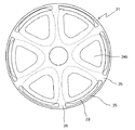
また、図2は上記アキシャルギャップ型モータのステータ21の平面図を示している。図2に示すように、バックヨーク24aに対してコイル23と反対の側から軸方向にステータ21を見ると、応力緩和孔25を介してコイル23の一部が見える。これにより、風や冷媒等を応力緩和孔25に通すことにより、コイル23を冷却することができる。
FIG. 2 is a plan view of the
また、上記ティース24bの外周側にある応力緩和孔25は、ティース24bをバックヨーク24aに圧入したときの応力緩和としても役に立つ場合もある。
Further, the
図1に示すように、上記ロータ31は、シャフト(図示せず)に取り付けられた円環状のバックヨーク34と、このバックヨーク34のステータ21側の一面に設けられた永久磁石33とを有する。
As shown in FIG. 1, the
上記バックヨーク34は、磁性体からなる。上記永久磁石33は、シャフトの周方向に交互に異なる磁極を有する。上記永久磁石33は、シャフトに沿った方向の磁束を発生する。
The
次に、上記ステータ21の組立方法について述べる。
Next, a method for assembling the
上記ティース24b先端のエアギャップに対向する側の面を治具(図示せず)の基準面に向けて、治具上にティース24bを載置する。
The
次に、治具上に載置されたティース24bに、予め整列巻したコイル23を外嵌して配置する。このとき、コイル23と、ティース24bおよびバックヨーク24aとの絶縁は、コイル23側か、ティース24bおよびバックヨーク24aの側のいずれかに設ければよい。
Next, the
そうして、ティース24bの回りにコイル23が配置された状態で、ティース24bにバックヨーク24aを上方から載置して、ティース24bの上部がバックヨーク24aの凹部に埋め込むようにした後、バックヨーク24aとティース24bとを接合する。治具の基準面は精度の良い平面を呈している。
Then, with the
上記ステータ21の組立方法によれば、ステータコア24を容易に組み立てることができる。なお、予め所定の形状に巻回された状態のコイル23をバックヨーク24a上に配置した後、バックヨーク24aと複数のティース24bとを接合しても、ステータコア24を容易に組み立てることができる。また、ティース24bまわりにコイル23を直接巻回した後、バックヨーク24aに接合しても良い。このとき、巻線ノズルをティース24bまわりで旋回させてもよく、ティース24bそのものを回転させてもよい。
According to the method for assembling the
また、上記ティース24bのロータ31と対向する側の平面を基準にしてバックヨーク24aとティース24bとを接合するので、エアギャップ精度を向上できる。
Further, since the
なお、この第1実施形態のモータにおいて、巻線方式は、集中巻、分布巻、波巻等に限らず、自由に選択することができる。また、ステータティース数とロータ極数の組合せおよび比率は自由である。 In the motor of the first embodiment, the winding method is not limited to concentrated winding, distributed winding, wave winding, and the like, and can be freely selected. Moreover, the combination and ratio of the number of stator teeth and the number of rotor poles are free.
〔第2実施形態〕
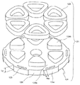
図3はこの発明の第2実施形態のアキシャルギャップ型モータのステータを軸方向に分解した斜視図を示している。この第2実施形態のアキシャルギャップ型モータは、バックヨーク124aの外周にコアカット部126を有する。以下の実施形態において、既述の実施形態と同様の構成については同一符号を付してその説明を省略する。
[Second Embodiment]
FIG. 3 is a perspective view in which the stator of the axial gap motor according to the second embodiment of the present invention is disassembled in the axial direction. The axial gap type motor of the second embodiment has a
このコアカット部126は、冷媒の通路や冷却のための風の通路等に用いられる。この場合、バックヨーク124aの、外周にケーシング(図示せず)の内周が接触する部分のみ、応力緩和孔125を有すれば良い。
The core cut
また、応力緩和孔125とコアカット部126との間の最小間隔Wzを、応力緩和孔125が設けられた部分のバックヨーク124aの厚さLyよりも小さくしている。これにより、バックヨーク124aの固定部124cをケーシングの内周に固定する焼きばめ時(または圧入時)の応力によりバックヨーク124aが面内変形して軸方向に変位しないので、エアギャップ精度が向上すると共に、バックヨーク124aのティース124b周りで歪が緩和されるため、磁気特性の劣化がない。
Further, the minimum interval Wz between the
図4はこの第2実施形態のアキシャルギャップ型モータのステータコア124を軸方向に分解した斜視図を示しており、ステータコア124は、バックヨーク124aに設けられた貫通孔127にティース124bを挿入した後、バックヨーク124aにティース124bを接合している。
FIG. 4 is a perspective view in which the
上記第2実施形態では、別体のバックヨーク124aとティース124bとを接合したステータコア124を用いたが、バックヨークとティースを一体に形成されたステータコアでもよい。
In the second embodiment, the
〔第3実施形態〕
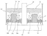
図5はこの発明の第3実施形態のアキシャルギャップ型モータの要部の断面図を示している。この第3実施形態のアキシャルギャップ型モータでは、軸流ファン40により発生する風の通り道が応力緩和孔25を経由する。
[Third Embodiment]
FIG. 5 shows a cross-sectional view of a main part of an axial gap type motor according to a third embodiment of the present invention. In the axial gap type motor of the third embodiment, the path of the wind generated by the
図5に示すアキシャルギャップ型モータのステータ21は、ティース24bが孔24cにおいてバックヨーク24aを貫通している。
In the
上記ステータ21は、図5に示すように、ケーシング101の内側に例えば圧入または焼きばめにより取り付けられたステータコア24と、このステータコア24に取り付けられたコイル23とを有する。
As shown in FIG. 5, the
上記ステータコア24は、シャフト20に対して略直交するように配置された円環状のバックヨーク24aと、このバックヨーク24aのロータ31側に立設されたティース24bとを有する。上記ティース24bは、シャフト20の軸方向に沿ってロータ31側に向かって延びており、シャフト20の周りに複数個設けられている。上記各ティース24bの軸周りに、コイル23を夫々巻回している。上記コイル23は、励磁されて、ティース24bに軸方向の磁束を発生する。
The
上記シャフト20の下端に軸流ファン40を取り付けている。
An
上記第3実施形態のアキシャルギャップ型モータによれば、軸流ファン40により発生する風が応力緩和孔25を通過することにより、コイル23を冷却することができる。
According to the axial gap type motor of the third embodiment, the wind generated by the
〔第4実施形態〕
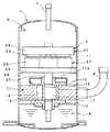
図6はこの発明の第4実施形態のアキシャルギャップ型モータを用いた圧縮機の縦断面図を示している。この圧縮機は、図6に示すように、ケーシングの一例としての密閉容器1と、上記密閉容器1内に配置されたアキシャルギャップ型モータ2と、密閉容器1内かつアキシャルギャップ型モータ2の下側に配置され、アキシャルギャップ型モータ2により駆動される圧縮機構部11とを備えている。ここで、上方向とは、上記密閉容器1の中心軸が水平面に対して傾斜しているか否かに関わらず、密閉容器1の中心軸に沿った上方向をいう。
[Fourth Embodiment]
FIG. 6 shows a longitudinal sectional view of a compressor using the axial gap type motor according to the fourth embodiment of the present invention. As shown in FIG. 6, the compressor includes a sealed
上記アキシャルギャップ型モータ2は、圧縮機構部11から吐出された高圧の冷媒が満たされる密閉容器1内の領域に配置されている。具体的には、上記密閉容器1内は、高圧領域Hであり、この圧縮機は、いわゆる高圧ドーム型である。
The axial
上記アキシャルギャップ型モータ2は、ステータ21と、このステータ21の上にエアギャップ41を介して配置されたロータ31と、このロータ31に固定され、かつ、このロータ31から延設されて軸受(図示せず)に回転自在に支持されたシャフト20とを有している。このロータ31の回転力を、シャフト20を介して圧縮機構部11に伝達する。
The axial
上記圧縮機構部11は、シリンダ状の本体部12と、この本体部12の上下の開口端のそれぞれに取り付けられる上端板15および下端板16とを備える。上記シャフト20は、上端板15および下端板16を貫通して、本体部12の内部に進入している。
The
上記本体部12の内部には、シャフト20に設けられたクランクピン17に嵌合したローラ13を、公転可能に配置し、このローラ13の公転運動で圧縮作用を行うようにしている。すなわち、上記ローラ13の外面と本体部12の内面との間に、圧縮室14を形成する。
A
上記密閉容器1は、圧縮機構部11の低圧側の圧縮室14に開口する吸入管6、および、アキシャルギャップ型モータ2の上側(下流側)に開口する吐出管7を有する。上記圧縮機構部11は、アキシャルギャップ型モータ2側に開口する吐出孔11aを有する。
The sealed
上記シャフト20の一端側は、圧縮機構部11の下端板16に回転自在に支持され、シャフト20の他端側は、ステータ21に回転自在に支持されている。
One end side of the
上記密閉容器1内の下側に、シャフト20の下部が浸漬される潤滑油8を有する。この潤滑油8は、シャフト20の回転によって、シャフト20の内部を上がって、圧縮機構部11の摺動部等を潤滑する。
On the lower side in the sealed
次に、上記圧縮機の作用を説明する。 Next, the operation of the compressor will be described.
上記吸入管6から圧縮機構部11の圧縮室14に冷媒を供給し、アキシャルギャップ型モータ2により圧縮機構部11を駆動させて、冷媒を圧縮する。圧縮された冷媒は、潤滑油と共に、圧縮機構部11の吐出孔11aから密閉容器1内に吐出され、アキシャルギャップ型モータ2を通って、吐出管7より密閉容器1の外側に吐出される。
The refrigerant is supplied from the suction pipe 6 to the
このとき、応力緩和孔25は、冷媒通路を兼ねる。
At this time, the
上記密閉容器1内の吸入口としての吸入管6と吐出口としての吐出管7との間にステータ21を配置することによって、ステータコア24のバックヨークに設けられた複数の応力緩和孔25を冷媒が通過して、コイル23を冷却することができるとともに、回転電機の上部の空間に吹き上げられた油を戻す通路としても働く。なお、応力緩和孔25以外にも通路を設けてもよい。
By disposing the
上記第4実施形態では、アキシャルギャップ型モータを用いたロータリー圧縮機について説明したが、ロータリー圧縮機に限らず、スクロール圧縮機等の他の圧縮機にこの発明のアキシャルギャップ型モータを適用してもよい。 In the fourth embodiment, the rotary compressor using the axial gap type motor has been described. However, the axial gap type motor of the present invention is not limited to the rotary compressor but applied to other compressors such as a scroll compressor. Also good.
また、上記第4実施形態では、被駆動部としての圧縮機構部11をアキシャルギャップ型モータ2により駆動したが、この発明のアキシャルギャップ型モータにより駆動される被駆動部は、圧縮機構部に限らず、アキシャルギャップ型モータの主軸の回転により駆動される他の構成の被駆動部であってもよい。
Moreover, in the said 4th Embodiment, although the
また、上記第1〜第4実施形態では、ステータの片側にエアギャップを介してロータが対向するアキシャルギャップ型モータについて説明したが、ステータの両側にステータを挟むようにエアギャップを介して2つのロータが対向するアキシャルギャップ型モータにこの発明を適用してもよい。 In the first to fourth embodiments, the axial gap type motor in which the rotor is opposed to one side of the stator via the air gap has been described. However, the two gaps are interposed via the air gap so that the stator is sandwiched on both sides of the stator. The present invention may be applied to an axial gap type motor that faces the rotor.
〔第5実施形態〕
図7はこの発明の第5実施形態のアキシャルギャップ型モータの要部を軸方向に分解した斜視図を示している。
[Fifth Embodiment]
FIG. 7 shows a perspective view of an essential part of an axial gap type motor according to a fifth embodiment of the present invention exploded in the axial direction.
図7に示すように、アキシャルギャップ型モータは、ステータ221,234と、このステータ221,234の間に配置されたロータ233と、ロータ233から延設されて軸受(図示せず)に回転自在に支持されるシャフト(図示せず)とを有している。上記ロータ233の回転力を、シャフトを介して負荷に伝達する。なお実際には、ステータ221とロータ233との間及びステータ234とロータ233との間にはそれぞれエアギャップが介在する。
As shown in FIG. 7, the axial gap type motor includes
上記ステータ221は、第1実施形態のコイル23、バックヨーク24a及びティース24bにそれぞれ相当して、コイル223、バックヨーク224a及びティース224bを有している。コイル223はティース224bに巻回されており、ここでは集中巻の場合が例示されている。
The
ステータ221はさらに、バックヨーク224aとは反対側で、ティース224bを各々独立して覆う磁性板236を有している。ここでは磁性板236同士が内周側及び外周側のそれぞれで、磁気飽和しやすく実質的には磁気障壁として機能する薄肉部によって連結されている。なお、この第5実施形態においては、ティース224b及びコイル223はそれぞれ12あり、ステータ221は8極となる。つまり、このステータ221は、集中巻8極12スロットに相当すると考えられる。また、巻線は3相で、例えば周方向にU相、V相、W相、U相、…に配置され、それぞれ3相はスター結線され、インバータから電流が供給される。
The
上記ロータ233は永久磁石233aと、永久磁石233aをそれぞれ独立して挟む磁性板233b,233cとを有する。図示していないが、永久磁石233a及び磁性板233b,233cを、非磁性体によって保持し、シャフトと締結している。非磁性体は、例えば樹脂モールドや、永久磁石233a及び磁性板233b,233cがはまる孔が設けられた非磁性体のホルダであってもよい。
The
ステータ234は、ロータ233のステータ221とは反対の側の磁束を短絡し、ロータ233とステータ221との間に働く磁気的な吸引力をキャンセルする機能を担う。
The
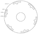
図8は、上記アキシャルギャップ型モータのバックヨーク224aの平面図である。バックヨーク224aには、複数の孔(応力緩和孔)225が設けられている。応力緩和孔225は、何れもコイル223を避けて設けられており、ティース224bの最外周を繋ぐ円より外側においてバックヨーク224aの外周に沿った形状のアーチ部225aと、上記アーチ部225aの中心から内周側に突出した凸部225bとを有している。すなわち、応力緩和孔225は、コイル223同士の間でもバックヨーク224aを軸方向に貫通する。したがって、モータ特性を損なうことなく、コイル223に熱が伝わるのを防止する。さらに、上記第1〜第4実施形態の応力緩和孔25よりも冷媒や冷却風を通すことに優れている。なお、ステータ234にも、ステータ221と同じ位置に孔225を設けているが、同じ位置に限定されない。
FIG. 8 is a plan view of the
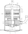
図9は、上記アキシャルギャップ型モータを用いた圧縮機の縦断面図である。この圧縮機は、上記第4実施形態と同様、密閉容器1と、上記密閉容器1内に配置されたアキシャルギャップ型モータ22と、上記密閉容器1内で、かつ、アキシャルギャップ型モータ22の下側に配置され、アキシャルギャップ型モータ22により駆動される圧縮機構部11とを備えている。
FIG. 9 is a longitudinal sectional view of a compressor using the above axial gap type motor. As in the fourth embodiment, the compressor includes a
上記ステータコア224は、例えばケーシングの内周において、溶接部28で溶接されている。溶接部28は、通常、ステータコア224の外周端部において等間隔で3箇所以上、ここでは6箇所であり、応力緩和孔225の外側に選定されている。ここで、溶接部28の幅は、応力緩和孔225の幅と同じかまたはより小(すなわち、溶接部28の幅より応力緩和孔225の幅が大)であるので、溶接によるバックヨークの歪を防止する。
The
また、溶接部28近傍のステータコア224は、軸方向の厚みに比べ、径方向の厚みが小さいので、応力がかかっても、空隙の平面度には影響しない。これにより、焼きばめ時または圧入時の応力によりバックヨーク224aが面内変形しても、軸方向に変位しない。これにより、エアギャップ精度が向上すると共に、バックヨーク224aのティース224b周りで歪が緩和されるため、磁気特性の劣化がない。
Further, the
なお、溶接は、バックヨーク224aをケーシングに焼きばめまたは圧入した後に溶接しても良い。また、溶接は、何れの側からしてもよく、両側からしてもよい。また、溶接する際には、ステータコア224の空隙面を基準にして行うことにより、精度よくステータ221をケーシングに固定することができる。
The welding may be performed after the
〔第6実施形態〕
図10はこの発明の第6実施形態のアキシャルギャップ型モータが有する回転電機を搭載した圧縮機の縦断面図である。この第6実施形態のアキシャルギャップ型モータは、ロータの両側にステータを有する。ステータ及びロータの構造は上記第5実施形態と同じであるので説明を省略する。この圧縮機では、ステータが2つあり、何れのステータもバックヨークの外周端部においてケーシングの内側に溶接されている。
[Sixth Embodiment]
FIG. 10 is a longitudinal sectional view of a compressor equipped with a rotating electrical machine included in an axial gap motor according to a sixth embodiment of the present invention. The axial gap type motor of the sixth embodiment has stators on both sides of the rotor. Since the structure of the stator and the rotor is the same as that of the fifth embodiment, description thereof is omitted. In this compressor, there are two stators, and each stator is welded to the inside of the casing at the outer peripheral end of the back yoke.
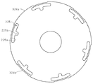
図11は上記アキシャルギャップ型モータのバックヨーク324aの平面図である。この第6実施形態でのバックヨーク324aは、溶接部28に対応する位置において、径をやや小さくして凹部324bを形成してある。なお、図11では分かり易いように描いているが、実際には、溶接部28に対応する部分のみ、焼きばめまたは圧入しないか、締め代が他の部分より小さい程度でよい。その部分は、溶接にて保持される。つまり、圧縮機が仮に高温になって、ケーシングが大きくなり、締め代が甘くなっても、溶接によって保持されるようになっている。
FIG. 11 is a plan view of the
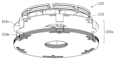
図12は上記アキシャルギャップ型モータの要部を軸方向に分解した斜視図である。図12では、バックヨーク324aから軸方向に突出させた溶接部324cを設けている。これにより、溶接が容易になり、熱がコイル223に伝わりにくく、また、バックヨーク324aの円筒部に歪が生じない。なお、溶接部324cとバックヨーク324aとは一体化されていることが望ましいため、溶接部128も圧粉磁心(例えば、圧粉鉄心)であることが望ましい。
FIG. 12 is a perspective view in which the main part of the axial gap type motor is exploded in the axial direction. In FIG. 12, a welded
例えばバックヨーク324aを積層鋼板で形成する場合、外周側に応力緩和孔225が設けられている略円形の鋼板において、応力緩和孔225の径方向外側の半径を、他の部分よりも、鋼板の板厚程度小さくして凹部324bを形成する。この鋼板を、応力緩和孔225が軸方向に貫通するように積層し、最も界磁子に近い1枚だけ、その凹部324bが形成される位置において、軸方向に沿って界磁子とは反対側に屈曲して突出する屈曲部324cを形成する。屈曲部324cの端部が溶接部128に相当し、ケーシングに溶接される。つまり、屈曲部324cの長さは、積層される鋼板の積層厚みを超える必要がある。なお、積層鋼板からなるバックヨーク324aそのものは、カラマセ等により、締結されていることが前提である。また、屈曲部324cを形成する鋼板は、必ずしも1枚である必要はなく、必要に応じて枚数を増やしてもよい。その場合には、凹部324bにおける鋼板の半径(すなわち、凹部324bの凹み具合)、屈曲部324cにおける鋼板の半径や屈曲部324cの長さ等を適宜変更する必要がある。
For example, when the
図13は上記アキシャルギャップ型モータが有する回転電機を搭載した圧縮機の縦断面図である。図13に示すように、この屈曲部324cの端部が溶接部128に相当し、ケーシングに溶接される。この圧縮機で使用される冷媒がCO2であるとき、ケーシング内部は高圧になるので、ケーシングの厚みが増加する。ケーシングの厚みが増加すると、焼きばめ時の体積変化が大きくなり、バックヨークとケーシングとを強固に固定することが困難になるため、溶接による固定が必須となる。またケーシング内部が高圧となることにより、潤滑油はアキシャルギャップ型モータよりも上側へ上昇しやすくなる。これを下方へ戻すためにも、応力緩和孔225が凸部225bを有していることは、冷媒としてCO2を採用する場合に好適である。したがって、CO2を冷媒として使用する給湯器や空調機の圧縮機には、このアキシャルギャップ型モータが好適である。
FIG. 13 is a longitudinal sectional view of a compressor equipped with a rotating electrical machine included in the axial gap type motor. As shown in FIG. 13, the end of the
なお、図10あるいは図13に示されたように、ロータの両側にステータを有するアキシャルギャップ型モータにおける溶接は、例えば次の手順を採用することができる。 As shown in FIG. 10 or FIG. 13, for example, the following procedure can be adopted for welding in an axial gap type motor having stators on both sides of the rotor.
まず下側のステータのバックヨークをケーシング1の内壁に溶接する。次に圧縮機構部11を下側から組込む。そしてロータ233及びシャフト20を上方からケーシング1に組込む。その後、上側のステータをロータ233の上方から組入れ、上側のステータのバックヨーク224をケーシング1の内壁に溶接する。
First, the back yoke of the lower stator is welded to the inner wall of the
あるいは、下側のステータのバックヨークの溶接位置を、バックヨークの上側に採る場合には次の手順を採用することができる。まず圧縮機構部11をケーシング1に組込む。そして下側のステータをケーシング1に組入れ、そのバックヨークをケーシング1の内壁に溶接する。そしてロータ233及びシャフト20を上方からケーシング1に組込む。その後、上側のステータをロータ233の上方から組入れ、上側のステータのバックヨーク224をケーシング1の内壁に溶接する。
Alternatively, when the welding position of the back yoke of the lower stator is set on the upper side of the back yoke, the following procedure can be adopted. First, the
1 密閉容器
2,22 アキシャルギャップ型モータ
20 シャフト
21,121,221,231,234 ステータ
23,123,223 コイル
24,124,224 ステータコア
24a,124a,224a,324a バックヨーク
24b,124b,224b ティース
25,125,225 応力緩和孔
26 連結部
31,231 ロータ
33,233a 永久磁石
34 バックヨーク
40 軸流ファン
101 ケーシング
124c 固定部
126 コアカット部
127 貫通孔
DESCRIPTION OF
Claims (23)
上記ステータ(21,121)の上記ティース(24b,124b)の先端に所定のエアギャップを隔てて対向すると共に、上記所定の回転軸を中心に回転するロータ(31)と、
上記ステータ(21,121)と上記ロータ(31)とを収納するケーシング(1)と
を備え、
上記ステータ(21,121)の上記ヨーク(24a,124a,224a)の外周が、上記ケーシング(1)の内周に固定され、
上記ヨーク(24a,124a,224a)の外周側かつ少なくとも上記ティース(24b,124b)よりも半径方向外側で上記ヨーク(24a,124a,224a)を軸方向に貫通する複数の孔(25,125,225)を設け、
前記孔と前記コイルの一部とが前記軸方向で互いに対向することを特徴とするアキシャルギャップ型モータ。 A yoke (24a, 124a, 224a) made of a substantially annular magnetic body that is substantially orthogonal to a predetermined rotation axis, and at least one end face side of the yoke (24a, 124a, 224a) so as to stand in the axial direction. A stator (21, 121) having teeth (24b, 124b) made of a magnetic material provided in the circumferential direction and coils (23, 123) wound around the teeth (24b, 124b);
A rotor (31) opposed to a tip of the teeth (24b, 124b) of the stator (21, 121) with a predetermined air gap and rotating about the predetermined rotation axis;
A casing (1) for housing the stator (21, 121) and the rotor (31);
The outer periphery of the yoke (24a, 124a, 224a) of the stator (21, 121) is fixed to the inner periphery of the casing (1),
A plurality of holes (25, 125, 224) that penetrate the yoke (24a, 124a, 224a) in the axial direction at the outer peripheral side of the yoke (24a, 124a, 224a) and at least radially outside the teeth (24b, 124b). 225) ,
The axial gap type motor, wherein the hole and a part of the coil face each other in the axial direction .
上記複数の孔(25,125,225)は、3以上であって、周方向にかつ略等間隔に配置されていることを特徴とするアキシャルギャップ型モータ。 The axial gap type motor according to claim 1,
The axial gap type motor characterized in that the plurality of holes (25, 125, 225) are three or more, and are arranged in the circumferential direction at substantially equal intervals.
互いに隣接する上記孔(25,125,225)間の連結部が、上記ティース(24b,124b)間の領域の半径方向外側にあることを特徴とするアキシャルギャップ型モータ。 In the axial gap type motor according to claim 1 or 2,
An axial gap type motor characterized in that a connecting portion between the holes (25, 125, 225) adjacent to each other is radially outside a region between the teeth (24b, 124b).
上記ヨーク(124a)の外周部に、上記ケーシングの内周に接触しないコアカット部(126)が設けられ、
上記複数の孔(215)は、上記コアカット部(126)および上記コアカット部(125)近傍を除く領域に設けられていることを特徴とするアキシャルギャップ型モータ。 The axial gap type motor according to claim 1,
A core cut portion (126) that does not contact the inner periphery of the casing is provided on the outer periphery of the yoke (124a),
The axial gap motor, wherein the plurality of holes (215) are provided in a region excluding the core cut portion (126) and the vicinity of the core cut portion (125).
上記ステータ(21,121)の上記ティース(24b,124b)の先端に所定のエアギャップを隔てて対向すると共に、上記所定の回転軸を中心に回転するロータ(31)と、
上記ステータ(21,121)と上記ロータ(31)とを収納するケーシング(1)と
を備え、
上記ステータ(21,121)の上記ヨーク(24a,124a,224a)の外周が、上記ケーシング(1)の内周に固定され、
上記ヨーク(24a,124a,224a)の外周側かつ少なくとも上記ティース(24b,124b)よりも半径方向外側で上記ヨーク(24a,124a,224a)を軸方向に貫通する複数の孔(25,125,225)を設け、
互いに隣接する上記孔(25,125,225)間の最小間隔は、上記孔(25,125,225)が設けられた部分の上記ヨーク(24a,124a,224a)の厚さよりも小さいことを特徴とするアキシャルギャップ型モータ。 A yoke (24a, 124a, 224a) made of a substantially annular magnetic body that is substantially orthogonal to a predetermined rotation axis, and at least one end face side of the yoke (24a, 124a, 224a) so as to stand in the axial direction. A stator (21, 121) having teeth (24b, 124b) made of a magnetic material provided in the circumferential direction and coils (23, 123) wound around the teeth (24b, 124b);
A rotor (31) opposed to a tip of the teeth (24b, 124b) of the stator (21, 121) with a predetermined air gap and rotating about the predetermined rotation axis;
A casing (1) for housing the stator (21, 121) and the rotor (31);
With
The outer periphery of the yoke (24a, 124a, 224a) of the stator (21, 121) is fixed to the inner periphery of the casing (1),
A plurality of holes (25, 125, 224) that penetrate the yoke (24a, 124a, 224a) in the axial direction at the outer peripheral side of the yoke (24a, 124a, 224a) and at least radially outside the teeth (24b, 124b). 225),
The minimum distance between the adjacent holes (25, 125, 225) is smaller than the thickness of the yoke (24a, 124a, 224a) where the holes (25, 125, 225) are provided. Axial gap type motor.
上記複数の孔(125)と上記コアカット部(126)との間の最小間隔は、上記孔(125)が設けられた部分の上記ヨーク(124a)の厚さよりも小さいことを特徴とするアキシャルギャップ型モータ。 In the axial gap type motor according to claim 4,
Axial characterized in that a minimum distance between the plurality of holes (125) and the core cut part (126) is smaller than a thickness of the yoke (124a) in a portion where the hole (125) is provided. Gap type motor.
上記ステータ(21,121)の上記ティース(24b,124b)の先端に所定のエアギャップを隔てて対向すると共に、上記所定の回転軸を中心に回転するロータ(31)と、
上記ステータ(21,121)と上記ロータ(31)とを収納するケーシング(1)と
を備え、
上記ステータ(21,121)の上記ヨーク(24a,124a,224a)の外周が、上記ケーシング(1)の内周に固定され、
上記ヨーク(24a,124a,224a)の外周側かつ少なくとも上記ティース(24b,124b)よりも半径方向外側で上記ヨーク(24a,124a,224a)を軸方向に貫通する複数の孔(25,125,225)を設け、
上記複数の孔(25,125,225)の領域を軸方向に投影した部分には、少なくとも上記コイル(23,123)の一部が重なることを特徴とするアキシャルギャップ型モータ。 A yoke (24a, 124a, 224a) made of a substantially annular magnetic body that is substantially orthogonal to a predetermined rotation axis, and at least one end face side of the yoke (24a, 124a, 224a) so as to stand in the axial direction. A stator (21, 121) having teeth (24b, 124b) made of a magnetic material provided in the circumferential direction and coils (23, 123) wound around the teeth (24b, 124b);
A rotor (31) opposed to a tip of the teeth (24b, 124b) of the stator (21, 121) with a predetermined air gap and rotating about the predetermined rotation axis;
A casing (1) for housing the stator (21, 121) and the rotor (31);
With
The outer periphery of the yoke (24a, 124a, 224a) of the stator (21, 121) is fixed to the inner periphery of the casing (1),
A plurality of holes (25, 125, 224) that penetrate the yoke (24a, 124a, 224a) in the axial direction at the outer peripheral side of the yoke (24a, 124a, 224a) and at least radially outside the teeth (24b, 124b). 225),
An axial gap type motor characterized in that at least a part of the coil (23, 123) overlaps with a portion of the plurality of holes (25, 125, 225) projected in the axial direction.
軸流ファン(40)を駆動するアキシャルギャップ型モータであって、
上記軸流ファン(40)の風通路に、上記複数の孔(25)を配置したことを特徴とするアキシャルギャップ型モータ。 In the axial gap type motor according to claim 7,
An axial gap motor for driving the axial fan (40),
An axial gap type motor, wherein the plurality of holes (25) are arranged in a wind passage of the axial fan (40).
上記ケーシング(1)に設けられた吸入口から冷媒を吸入して、上記ケーシング(1)に設けられた吐出口から上記冷媒を吐出する圧縮機構部(11)を駆動するアキシャルギャップ型モータであって、
上記ステータ(21,121)は、上記吸入口から上記吐出口までの間に配置されていることを特徴とするアキシャルギャップ型モータ。 In the axial gap type motor according to claim 7,
An axial gap motor that drives a compression mechanism (11) that sucks refrigerant from an inlet provided in the casing (1) and discharges the refrigerant from an outlet provided in the casing (1). And
The axial gap type motor, wherein the stator (21, 121) is disposed between the suction port and the discharge port.
上記ヨーク(24a,124a,224a)のうち、少なくとも上記ケーシング(1)の内周に焼きばめまたは圧入される部分と上記複数の孔(25,125,225)の周辺部分は、薄板が軸方向に積層された積層鋼板により一体に形成されていることを特徴とするアキシャルギャップ型モータ。 In the axial gap type motor according to any one of claims 1 to 9,
Of the yoke (24a, 124a, 224a), at least a portion that is shrink-fitted or press-fitted into the inner periphery of the casing (1) and a peripheral portion of the plurality of holes (25, 125, 225) are thin plates. An axial gap motor characterized by being integrally formed of laminated steel plates laminated in a direction.
上記ティース(24b,124b)は、圧粉磁心からなり、上記ヨーク(24a,124a,224a)内に軸方向に所定の深さ埋め込まれているか、または、上記ヨーク(24a,124a,224a)内に軸方向に貫通するように埋め込まれていることを特徴とするアキシャルギャップ型モータ。 In the axial gap type motor according to claim 10,
The teeth (24b, 124b) are made of a dust core and are embedded in the yokes (24a, 124a, 224a) in a predetermined depth in the axial direction, or in the yokes (24a, 124a, 224a). An axial gap type motor characterized by being embedded so as to penetrate in the axial direction.
上記ステータ(221)の上記ヨーク(24a,124a,224a)の外周のうち、上記複数の孔(25,125,225)が周方向に延在する範囲内で、上記ケーシング(1)の内周に溶接により固定された、アキシャルギャップ型モータ。 In the axial gap type motor according to claim 1 or 2,
Of the outer periphery of the yoke (24a, 124a, 224a) of the stator (221), the inner periphery of the casing (1) is within a range in which the plurality of holes (25, 125, 225) extend in the circumferential direction. Axial gap type motor fixed to the machine by welding.
上記孔(25,225)は、少なくとも上記ティース(24b,224b)の間の径方向外側に延長した部分に設けられている、アキシャルギャップ型モータ。 The axial gap type motor according to claim 12,
The hole (25, 225) is an axial gap type motor provided in at least a portion extending radially outward between the teeth (24b, 224b).
上記孔(25,125,225)は、上記コイル(23,123,223)を避けて貫通する部分を有する、アキシャルギャップ型モータ。 In the axial gap type motor according to claim 12 or 13,
The axial gap type motor, wherein the holes (25, 125, 225) have a portion that penetrates the coil (23, 123, 223).
上記孔(225)は、周方向に隣接する上記コイル(223)の間でも上記ヨーク(224a)を軸方向に貫通する、アキシャルギャップ型モータ。 In the axial gap type motor according to claim 14,
The axial gap type motor in which the hole (225) penetrates the yoke (224a) in the axial direction even between the coils (223) adjacent in the circumferential direction.
上記ステータ(21,121)の上記ティース(24b,124b)の先端に所定のエアギャップを隔てて対向すると共に、上記所定の回転軸を中心に回転するロータ(31)と、
上記ステータ(21,121)と上記ロータ(31)とを収納するケーシング(1)と
を備え、
上記ステータ(21,121)の上記ヨーク(24a,124a,224a)の外周が、上記ケーシング(1)の内周に固定され、
上記ヨーク(24a,124a,224a)の外周側かつ少なくとも上記ティース(24b,124b)よりも半径方向外側で上記ヨーク(24a,124a,224a)を軸方向に貫通する複数の孔(25,125,225)を設け、
上記ステータ(221)の上記ヨーク(24a,124a,224a)の外周のうち、上記複数の孔(25,125,225)が周方向に延在する範囲内で、上記ケーシング(1)の内周に溶接により固定され、
上記ヨーク(24a,124a,224a)は、上記溶接が施された箇所と上記孔(25,125,225)との間において、軸方向厚みに比べ、径方向厚みが小さい、アキシャルギャップ型モータ。 A yoke (24a, 124a, 224a) made of a substantially annular magnetic body that is substantially orthogonal to a predetermined rotation axis, and at least one end face side of the yoke (24a, 124a, 224a) so as to stand in the axial direction. A stator (21, 121) having teeth (24b, 124b) made of a magnetic material provided in the circumferential direction and coils (23, 123) wound around the teeth (24b, 124b);
A rotor (31) opposed to a tip of the teeth (24b, 124b) of the stator (21, 121) with a predetermined air gap and rotating about the predetermined rotation axis;
A casing (1) for housing the stator (21, 121) and the rotor (31);
With
The outer periphery of the yoke (24a, 124a, 224a) of the stator (21, 121) is fixed to the inner periphery of the casing (1),
A plurality of holes (25, 125, 224) that penetrate the yoke (24a, 124a, 224a) in the axial direction at the outer peripheral side of the yoke (24a, 124a, 224a) and at least radially outside the teeth (24b, 124b). 225),
Of the outer periphery of the yoke (24a, 124a, 224a) of the stator (221), the inner periphery of the casing (1) is within a range in which the plurality of holes (25, 125, 225) extend in the circumferential direction. Fixed by welding ,
The axial gap type motor in which the yoke (24a, 124a, 224a) has a smaller radial thickness than an axial thickness between the welded portion and the hole (25, 125, 225).
上記孔(225)の外周側で、上記ヨーク(224a)の外周端部から軸方向に突出した溶接部(324c)を有し、
上記溶接部(324c)において上記ヨーク(224a)と上記ケーシング(1)とが溶接される、アキシャルギャップ型モータ。 The axial gap type motor according to any one of claims 12 to 16,
On the outer peripheral side of the hole (225), it has a welded part (324c) protruding in the axial direction from the outer peripheral end of the yoke (224a),
An axial gap type motor in which the yoke (224a) and the casing (1) are welded at the welded portion (324c).
上記ヨーク(24a,124a,224a)は、軸方向に積層された鋼板からなる、アキシャルギャップ型モータ。 The axial gap type motor according to any one of claims 12 to 17,
The yoke (24a, 124a, 224a) is an axial gap type motor made of steel plates laminated in the axial direction.
上記ヨーク(24a,124a,224a)は、圧粉鉄心からなる、アキシャルギャップ型モータ。 The axial gap type motor according to any one of claims 12 to 18,
The yoke (24a, 124a, 224a) is an axial gap type motor composed of a dust core.
上記ヨーク(24a,124a,224a)は、上記ケーシング(1)に圧入または焼きばめもされている、アキシャルギャップ型モータ。 In the axial gap type motor according to any one of claims 12 to 19,
The axial gap type motor in which the yoke (24a, 124a, 224a) is press-fitted or shrink-fitted into the casing (1).
上記溶接が施された箇所を除く、上記ヨーク(24a,124a,224a)の外周端部が上記ケーシング(1)と圧入または焼きばめされている、アキシャルギャップ型モータ。 The axial gap type motor according to claim 20,
An axial gap type motor in which an outer peripheral end portion of the yoke (24a, 124a, 224a) is press-fitted or shrink-fitted with the casing (1) excluding the place where the welding is performed.
冷媒がCO2である、圧縮機。 The compressor according to claim 22, wherein
A compressor, wherein the refrigerant is CO 2 .
Priority Applications (1)
| Application Number | Priority Date | Filing Date | Title |
|---|---|---|---|
| JP2007103774A JP5040407B2 (en) | 2006-05-12 | 2007-04-11 | Axial gap type motor and compressor |
Applications Claiming Priority (3)
| Application Number | Priority Date | Filing Date | Title |
|---|---|---|---|
| JP2006133214 | 2006-05-12 | ||
| JP2006133214 | 2006-05-12 | ||
| JP2007103774A JP5040407B2 (en) | 2006-05-12 | 2007-04-11 | Axial gap type motor and compressor |
Publications (2)
| Publication Number | Publication Date |
|---|---|
| JP2007330092A JP2007330092A (en) | 2007-12-20 |
| JP5040407B2 true JP5040407B2 (en) | 2012-10-03 |
Family
ID=38930163
Family Applications (1)
| Application Number | Title | Priority Date | Filing Date |
|---|---|---|---|
| JP2007103774A Expired - Fee Related JP5040407B2 (en) | 2006-05-12 | 2007-04-11 | Axial gap type motor and compressor |
Country Status (1)
| Country | Link |
|---|---|
| JP (1) | JP5040407B2 (en) |
Cited By (1)
| Publication number | Priority date | Publication date | Assignee | Title |
|---|---|---|---|---|
| WO2021145136A1 (en) | 2020-01-14 | 2021-07-22 | ヤマハ発動機株式会社 | Axial gap motor |
Families Citing this family (8)
| Publication number | Priority date | Publication date | Assignee | Title |
|---|---|---|---|---|
| JP4858565B2 (en) * | 2009-03-31 | 2012-01-18 | ダイキン工業株式会社 | Compressor |
| JP4858564B2 (en) * | 2009-03-31 | 2012-01-18 | ダイキン工業株式会社 | Compressor |
| WO2011152197A1 (en) * | 2010-06-02 | 2011-12-08 | アイシン精機株式会社 | Electrical rotary machine |
| JP5510079B2 (en) * | 2010-06-02 | 2014-06-04 | 富士電機株式会社 | Axial gap motor |
| KR101113397B1 (en) * | 2010-10-28 | 2012-02-28 | 대성전기공업 주식회사 | Rotary Actuator |
| JP6806210B1 (en) * | 2019-09-26 | 2021-01-06 | 株式会社富士通ゼネラル | Compressor |
| CN114287103B (en) * | 2019-10-17 | 2023-11-03 | 住友电气工业株式会社 | Rotary electric machine |
| JP7426280B2 (en) * | 2020-04-01 | 2024-02-01 | 三菱重工サーマルシステムズ株式会社 | compressor |
Family Cites Families (3)
| Publication number | Priority date | Publication date | Assignee | Title |
|---|---|---|---|---|
| JP2001136721A (en) * | 1999-08-26 | 2001-05-18 | Toyota Motor Corp | Axial gap type permanent magnet synchronous machine |
| JP4848665B2 (en) * | 2005-04-28 | 2011-12-28 | ダイキン工業株式会社 | Compressor |
| JP4618050B2 (en) * | 2005-08-29 | 2011-01-26 | ダイキン工業株式会社 | Compressor |
-
2007
- 2007-04-11 JP JP2007103774A patent/JP5040407B2/en not_active Expired - Fee Related
Cited By (3)
| Publication number | Priority date | Publication date | Assignee | Title |
|---|---|---|---|---|
| WO2021145136A1 (en) | 2020-01-14 | 2021-07-22 | ヤマハ発動機株式会社 | Axial gap motor |
| US12074489B2 (en) | 2020-01-14 | 2024-08-27 | Yamaha Hatsudoki Kabushiki Kaisha | Axial gap motor |
| US12081088B2 (en) | 2020-01-14 | 2024-09-03 | Yamaha Hatsudoki Kabushiki Kaisha | Axial-gap-dynamoelectric machine |
Also Published As
| Publication number | Publication date |
|---|---|
| JP2007330092A (en) | 2007-12-20 |
Similar Documents
| Publication | Publication Date | Title |
|---|---|---|
| JP5040407B2 (en) | Axial gap type motor and compressor | |
| KR101025366B1 (en) | Motor and compressor | |
| CN101652914B (en) | Rotating electric machine and compressor | |
| JP2008245504A (en) | Armature core manufacturing method and armature core | |
| US20100259125A1 (en) | Armature core, armature, rotary electric machine and compressor | |
| JP4529500B2 (en) | Axial gap rotating electric machine | |
| JP6999506B2 (en) | Brushless motor and its stator | |
| JPWO2007114079A1 (en) | Motor, motor manufacturing method and compressor | |
| JP5359112B2 (en) | Axial gap type rotating electrical machine and compressor using the same | |
| JP2008228363A (en) | Armature cores, armatures, rotating electrical machines, compressors | |
| JP2003274579A (en) | Stator of motor for hermetic compressor | |
| JP6545393B2 (en) | Conscious pole rotor, motor and air conditioner | |
| JP4715832B2 (en) | Motor, motor manufacturing method and compressor | |
| CN118407924A (en) | Rotating Equipment | |
| WO2023136117A1 (en) | Rotary electric machine | |
| JP2009077491A (en) | Stator core laminated body and electric motor | |
| JP6927343B1 (en) | Compressor | |
| JP5375534B2 (en) | Compressor and manufacturing method thereof | |
| JP4253574B2 (en) | Permanent magnet type rotating electric machine and compressor using the same | |
| TWI790636B (en) | electric motor | |
| JP2010288330A (en) | Stator for adder motor | |
| WO2020208988A1 (en) | Motor and electric device | |
| JP2008172918A (en) | Axial gap type motor and compressor | |
| JP5120126B2 (en) | Compressor | |
| JP2013126267A (en) | Rotating electric machine and compressor |
Legal Events
| Date | Code | Title | Description |
|---|---|---|---|
| RD04 | Notification of resignation of power of attorney |
Free format text: JAPANESE INTERMEDIATE CODE: A7424 Effective date: 20091105 |
|
| A621 | Written request for application examination |
Free format text: JAPANESE INTERMEDIATE CODE: A621 Effective date: 20091217 |
|
| A977 | Report on retrieval |
Free format text: JAPANESE INTERMEDIATE CODE: A971007 Effective date: 20120321 |
|
| A131 | Notification of reasons for refusal |
Free format text: JAPANESE INTERMEDIATE CODE: A131 Effective date: 20120327 |
|
| A521 | Written amendment |
Free format text: JAPANESE INTERMEDIATE CODE: A523 Effective date: 20120525 |
|
| TRDD | Decision of grant or rejection written | ||
| A01 | Written decision to grant a patent or to grant a registration (utility model) |
Free format text: JAPANESE INTERMEDIATE CODE: A01 Effective date: 20120612 |
|
| A01 | Written decision to grant a patent or to grant a registration (utility model) |
Free format text: JAPANESE INTERMEDIATE CODE: A01 |
|
| A61 | First payment of annual fees (during grant procedure) |
Free format text: JAPANESE INTERMEDIATE CODE: A61 Effective date: 20120625 |
|
| FPAY | Renewal fee payment (event date is renewal date of database) |
Free format text: PAYMENT UNTIL: 20150720 Year of fee payment: 3 |
|
| LAPS | Cancellation because of no payment of annual fees |

