WO2011145546A1 - 電動車両およびその制御方法 - Google Patents
電動車両およびその制御方法 Download PDFInfo
- Publication number
- WO2011145546A1 WO2011145546A1 PCT/JP2011/061154 JP2011061154W WO2011145546A1 WO 2011145546 A1 WO2011145546 A1 WO 2011145546A1 JP 2011061154 W JP2011061154 W JP 2011061154W WO 2011145546 A1 WO2011145546 A1 WO 2011145546A1
- Authority
- WO
- WIPO (PCT)
- Prior art keywords
- power
- value
- storage device
- power storage
- control
- Prior art date
Links
Images


Classifications
-
- B—PERFORMING OPERATIONS; TRANSPORTING
- B60—VEHICLES IN GENERAL
- B60K—ARRANGEMENT OR MOUNTING OF PROPULSION UNITS OR OF TRANSMISSIONS IN VEHICLES; ARRANGEMENT OR MOUNTING OF PLURAL DIVERSE PRIME-MOVERS IN VEHICLES; AUXILIARY DRIVES FOR VEHICLES; INSTRUMENTATION OR DASHBOARDS FOR VEHICLES; ARRANGEMENTS IN CONNECTION WITH COOLING, AIR INTAKE, GAS EXHAUST OR FUEL SUPPLY OF PROPULSION UNITS IN VEHICLES
- B60K6/00—Arrangement or mounting of plural diverse prime-movers for mutual or common propulsion, e.g. hybrid propulsion systems comprising electric motors and internal combustion engines ; Control systems therefor, i.e. systems controlling two or more prime movers, or controlling one of these prime movers and any of the transmission, drive or drive units Informative references: mechanical gearings with secondary electric drive F16H3/72; arrangements for handling mechanical energy structurally associated with the dynamo-electric machine H02K7/00; machines comprising structurally interrelated motor and generator parts H02K51/00; dynamo-electric machines not otherwise provided for in H02K see H02K99/00
- B60K6/20—Arrangement or mounting of plural diverse prime-movers for mutual or common propulsion, e.g. hybrid propulsion systems comprising electric motors and internal combustion engines ; Control systems therefor, i.e. systems controlling two or more prime movers, or controlling one of these prime movers and any of the transmission, drive or drive units Informative references: mechanical gearings with secondary electric drive F16H3/72; arrangements for handling mechanical energy structurally associated with the dynamo-electric machine H02K7/00; machines comprising structurally interrelated motor and generator parts H02K51/00; dynamo-electric machines not otherwise provided for in H02K see H02K99/00 the prime-movers consisting of electric motors and internal combustion engines, e.g. HEVs
- B60K6/42—Arrangement or mounting of plural diverse prime-movers for mutual or common propulsion, e.g. hybrid propulsion systems comprising electric motors and internal combustion engines ; Control systems therefor, i.e. systems controlling two or more prime movers, or controlling one of these prime movers and any of the transmission, drive or drive units Informative references: mechanical gearings with secondary electric drive F16H3/72; arrangements for handling mechanical energy structurally associated with the dynamo-electric machine H02K7/00; machines comprising structurally interrelated motor and generator parts H02K51/00; dynamo-electric machines not otherwise provided for in H02K see H02K99/00 the prime-movers consisting of electric motors and internal combustion engines, e.g. HEVs characterised by the architecture of the hybrid electric vehicle
- B60K6/44—Series-parallel type
- B60K6/445—Differential gearing distribution type
-
- B—PERFORMING OPERATIONS; TRANSPORTING
- B60—VEHICLES IN GENERAL
- B60L—PROPULSION OF ELECTRICALLY-PROPELLED VEHICLES; SUPPLYING ELECTRIC POWER FOR AUXILIARY EQUIPMENT OF ELECTRICALLY-PROPELLED VEHICLES; ELECTRODYNAMIC BRAKE SYSTEMS FOR VEHICLES IN GENERAL; MAGNETIC SUSPENSION OR LEVITATION FOR VEHICLES; MONITORING OPERATING VARIABLES OF ELECTRICALLY-PROPELLED VEHICLES; ELECTRIC SAFETY DEVICES FOR ELECTRICALLY-PROPELLED VEHICLES
- B60L3/00—Electric devices on electrically-propelled vehicles for safety purposes; Monitoring operating variables, e.g. speed, deceleration or energy consumption
- B60L3/0023—Detecting, eliminating, remedying or compensating for drive train abnormalities, e.g. failures within the drive train
- B60L3/0046—Detecting, eliminating, remedying or compensating for drive train abnormalities, e.g. failures within the drive train relating to electric energy storage systems, e.g. batteries or capacitors
-
- B—PERFORMING OPERATIONS; TRANSPORTING
- B60—VEHICLES IN GENERAL
- B60L—PROPULSION OF ELECTRICALLY-PROPELLED VEHICLES; SUPPLYING ELECTRIC POWER FOR AUXILIARY EQUIPMENT OF ELECTRICALLY-PROPELLED VEHICLES; ELECTRODYNAMIC BRAKE SYSTEMS FOR VEHICLES IN GENERAL; MAGNETIC SUSPENSION OR LEVITATION FOR VEHICLES; MONITORING OPERATING VARIABLES OF ELECTRICALLY-PROPELLED VEHICLES; ELECTRIC SAFETY DEVICES FOR ELECTRICALLY-PROPELLED VEHICLES
- B60L3/00—Electric devices on electrically-propelled vehicles for safety purposes; Monitoring operating variables, e.g. speed, deceleration or energy consumption
- B60L3/0092—Electric devices on electrically-propelled vehicles for safety purposes; Monitoring operating variables, e.g. speed, deceleration or energy consumption with use of redundant elements for safety purposes
-
- B—PERFORMING OPERATIONS; TRANSPORTING
- B60—VEHICLES IN GENERAL
- B60L—PROPULSION OF ELECTRICALLY-PROPELLED VEHICLES; SUPPLYING ELECTRIC POWER FOR AUXILIARY EQUIPMENT OF ELECTRICALLY-PROPELLED VEHICLES; ELECTRODYNAMIC BRAKE SYSTEMS FOR VEHICLES IN GENERAL; MAGNETIC SUSPENSION OR LEVITATION FOR VEHICLES; MONITORING OPERATING VARIABLES OF ELECTRICALLY-PROPELLED VEHICLES; ELECTRIC SAFETY DEVICES FOR ELECTRICALLY-PROPELLED VEHICLES
- B60L50/00—Electric propulsion with power supplied within the vehicle
- B60L50/10—Electric propulsion with power supplied within the vehicle using propulsion power supplied by engine-driven generators, e.g. generators driven by combustion engines
- B60L50/16—Electric propulsion with power supplied within the vehicle using propulsion power supplied by engine-driven generators, e.g. generators driven by combustion engines with provision for separate direct mechanical propulsion
-
- B—PERFORMING OPERATIONS; TRANSPORTING
- B60—VEHICLES IN GENERAL
- B60L—PROPULSION OF ELECTRICALLY-PROPELLED VEHICLES; SUPPLYING ELECTRIC POWER FOR AUXILIARY EQUIPMENT OF ELECTRICALLY-PROPELLED VEHICLES; ELECTRODYNAMIC BRAKE SYSTEMS FOR VEHICLES IN GENERAL; MAGNETIC SUSPENSION OR LEVITATION FOR VEHICLES; MONITORING OPERATING VARIABLES OF ELECTRICALLY-PROPELLED VEHICLES; ELECTRIC SAFETY DEVICES FOR ELECTRICALLY-PROPELLED VEHICLES
- B60L50/00—Electric propulsion with power supplied within the vehicle
- B60L50/50—Electric propulsion with power supplied within the vehicle using propulsion power supplied by batteries or fuel cells
- B60L50/60—Electric propulsion with power supplied within the vehicle using propulsion power supplied by batteries or fuel cells using power supplied by batteries
- B60L50/61—Electric propulsion with power supplied within the vehicle using propulsion power supplied by batteries or fuel cells using power supplied by batteries by batteries charged by engine-driven generators, e.g. series hybrid electric vehicles
-
- B—PERFORMING OPERATIONS; TRANSPORTING
- B60—VEHICLES IN GENERAL
- B60L—PROPULSION OF ELECTRICALLY-PROPELLED VEHICLES; SUPPLYING ELECTRIC POWER FOR AUXILIARY EQUIPMENT OF ELECTRICALLY-PROPELLED VEHICLES; ELECTRODYNAMIC BRAKE SYSTEMS FOR VEHICLES IN GENERAL; MAGNETIC SUSPENSION OR LEVITATION FOR VEHICLES; MONITORING OPERATING VARIABLES OF ELECTRICALLY-PROPELLED VEHICLES; ELECTRIC SAFETY DEVICES FOR ELECTRICALLY-PROPELLED VEHICLES
- B60L53/00—Methods of charging batteries, specially adapted for electric vehicles; Charging stations or on-board charging equipment therefor; Exchange of energy storage elements in electric vehicles
- B60L53/10—Methods of charging batteries, specially adapted for electric vehicles; Charging stations or on-board charging equipment therefor; Exchange of energy storage elements in electric vehicles characterised by the energy transfer between the charging station and the vehicle
- B60L53/14—Conductive energy transfer
-
- B—PERFORMING OPERATIONS; TRANSPORTING
- B60—VEHICLES IN GENERAL
- B60L—PROPULSION OF ELECTRICALLY-PROPELLED VEHICLES; SUPPLYING ELECTRIC POWER FOR AUXILIARY EQUIPMENT OF ELECTRICALLY-PROPELLED VEHICLES; ELECTRODYNAMIC BRAKE SYSTEMS FOR VEHICLES IN GENERAL; MAGNETIC SUSPENSION OR LEVITATION FOR VEHICLES; MONITORING OPERATING VARIABLES OF ELECTRICALLY-PROPELLED VEHICLES; ELECTRIC SAFETY DEVICES FOR ELECTRICALLY-PROPELLED VEHICLES
- B60L58/00—Methods or circuit arrangements for monitoring or controlling batteries or fuel cells, specially adapted for electric vehicles
- B60L58/10—Methods or circuit arrangements for monitoring or controlling batteries or fuel cells, specially adapted for electric vehicles for monitoring or controlling batteries
- B60L58/12—Methods or circuit arrangements for monitoring or controlling batteries or fuel cells, specially adapted for electric vehicles for monitoring or controlling batteries responding to state of charge [SoC]
- B60L58/13—Maintaining the SoC within a determined range
-
- B—PERFORMING OPERATIONS; TRANSPORTING
- B60—VEHICLES IN GENERAL
- B60W—CONJOINT CONTROL OF VEHICLE SUB-UNITS OF DIFFERENT TYPE OR DIFFERENT FUNCTION; CONTROL SYSTEMS SPECIALLY ADAPTED FOR HYBRID VEHICLES; ROAD VEHICLE DRIVE CONTROL SYSTEMS FOR PURPOSES NOT RELATED TO THE CONTROL OF A PARTICULAR SUB-UNIT
- B60W10/00—Conjoint control of vehicle sub-units of different type or different function
- B60W10/04—Conjoint control of vehicle sub-units of different type or different function including control of propulsion units
- B60W10/08—Conjoint control of vehicle sub-units of different type or different function including control of propulsion units including control of electric propulsion units, e.g. motors or generators
-
- B—PERFORMING OPERATIONS; TRANSPORTING
- B60—VEHICLES IN GENERAL
- B60W—CONJOINT CONTROL OF VEHICLE SUB-UNITS OF DIFFERENT TYPE OR DIFFERENT FUNCTION; CONTROL SYSTEMS SPECIALLY ADAPTED FOR HYBRID VEHICLES; ROAD VEHICLE DRIVE CONTROL SYSTEMS FOR PURPOSES NOT RELATED TO THE CONTROL OF A PARTICULAR SUB-UNIT
- B60W10/00—Conjoint control of vehicle sub-units of different type or different function
- B60W10/24—Conjoint control of vehicle sub-units of different type or different function including control of energy storage means
- B60W10/26—Conjoint control of vehicle sub-units of different type or different function including control of energy storage means for electrical energy, e.g. batteries or capacitors
-
- B—PERFORMING OPERATIONS; TRANSPORTING
- B60—VEHICLES IN GENERAL
- B60W—CONJOINT CONTROL OF VEHICLE SUB-UNITS OF DIFFERENT TYPE OR DIFFERENT FUNCTION; CONTROL SYSTEMS SPECIALLY ADAPTED FOR HYBRID VEHICLES; ROAD VEHICLE DRIVE CONTROL SYSTEMS FOR PURPOSES NOT RELATED TO THE CONTROL OF A PARTICULAR SUB-UNIT
- B60W20/00—Control systems specially adapted for hybrid vehicles
- B60W20/10—Controlling the power contribution of each of the prime movers to meet required power demand
- B60W20/13—Controlling the power contribution of each of the prime movers to meet required power demand in order to stay within battery power input or output limits; in order to prevent overcharging or battery depletion
-
- F—MECHANICAL ENGINEERING; LIGHTING; HEATING; WEAPONS; BLASTING
- F02—COMBUSTION ENGINES; HOT-GAS OR COMBUSTION-PRODUCT ENGINE PLANTS
- F02D—CONTROLLING COMBUSTION ENGINES
- F02D29/00—Controlling engines, such controlling being peculiar to the devices driven thereby, the devices being other than parts or accessories essential to engine operation, e.g. controlling of engines by signals external thereto
- F02D29/02—Controlling engines, such controlling being peculiar to the devices driven thereby, the devices being other than parts or accessories essential to engine operation, e.g. controlling of engines by signals external thereto peculiar to engines driving vehicles; peculiar to engines driving variable pitch propellers
-
- B—PERFORMING OPERATIONS; TRANSPORTING
- B60—VEHICLES IN GENERAL
- B60L—PROPULSION OF ELECTRICALLY-PROPELLED VEHICLES; SUPPLYING ELECTRIC POWER FOR AUXILIARY EQUIPMENT OF ELECTRICALLY-PROPELLED VEHICLES; ELECTRODYNAMIC BRAKE SYSTEMS FOR VEHICLES IN GENERAL; MAGNETIC SUSPENSION OR LEVITATION FOR VEHICLES; MONITORING OPERATING VARIABLES OF ELECTRICALLY-PROPELLED VEHICLES; ELECTRIC SAFETY DEVICES FOR ELECTRICALLY-PROPELLED VEHICLES
- B60L2210/00—Converter types
- B60L2210/10—DC to DC converters
- B60L2210/12—Buck converters
-
- B—PERFORMING OPERATIONS; TRANSPORTING
- B60—VEHICLES IN GENERAL
- B60L—PROPULSION OF ELECTRICALLY-PROPELLED VEHICLES; SUPPLYING ELECTRIC POWER FOR AUXILIARY EQUIPMENT OF ELECTRICALLY-PROPELLED VEHICLES; ELECTRODYNAMIC BRAKE SYSTEMS FOR VEHICLES IN GENERAL; MAGNETIC SUSPENSION OR LEVITATION FOR VEHICLES; MONITORING OPERATING VARIABLES OF ELECTRICALLY-PROPELLED VEHICLES; ELECTRIC SAFETY DEVICES FOR ELECTRICALLY-PROPELLED VEHICLES
- B60L2210/00—Converter types
- B60L2210/10—DC to DC converters
- B60L2210/14—Boost converters
-
- B—PERFORMING OPERATIONS; TRANSPORTING
- B60—VEHICLES IN GENERAL
- B60L—PROPULSION OF ELECTRICALLY-PROPELLED VEHICLES; SUPPLYING ELECTRIC POWER FOR AUXILIARY EQUIPMENT OF ELECTRICALLY-PROPELLED VEHICLES; ELECTRODYNAMIC BRAKE SYSTEMS FOR VEHICLES IN GENERAL; MAGNETIC SUSPENSION OR LEVITATION FOR VEHICLES; MONITORING OPERATING VARIABLES OF ELECTRICALLY-PROPELLED VEHICLES; ELECTRIC SAFETY DEVICES FOR ELECTRICALLY-PROPELLED VEHICLES
- B60L2240/00—Control parameters of input or output; Target parameters
- B60L2240/10—Vehicle control parameters
- B60L2240/36—Temperature of vehicle components or parts
-
- B—PERFORMING OPERATIONS; TRANSPORTING
- B60—VEHICLES IN GENERAL
- B60L—PROPULSION OF ELECTRICALLY-PROPELLED VEHICLES; SUPPLYING ELECTRIC POWER FOR AUXILIARY EQUIPMENT OF ELECTRICALLY-PROPELLED VEHICLES; ELECTRODYNAMIC BRAKE SYSTEMS FOR VEHICLES IN GENERAL; MAGNETIC SUSPENSION OR LEVITATION FOR VEHICLES; MONITORING OPERATING VARIABLES OF ELECTRICALLY-PROPELLED VEHICLES; ELECTRIC SAFETY DEVICES FOR ELECTRICALLY-PROPELLED VEHICLES
- B60L2240/00—Control parameters of input or output; Target parameters
- B60L2240/40—Drive Train control parameters
- B60L2240/42—Drive Train control parameters related to electric machines
- B60L2240/421—Speed
-
- B—PERFORMING OPERATIONS; TRANSPORTING
- B60—VEHICLES IN GENERAL
- B60L—PROPULSION OF ELECTRICALLY-PROPELLED VEHICLES; SUPPLYING ELECTRIC POWER FOR AUXILIARY EQUIPMENT OF ELECTRICALLY-PROPELLED VEHICLES; ELECTRODYNAMIC BRAKE SYSTEMS FOR VEHICLES IN GENERAL; MAGNETIC SUSPENSION OR LEVITATION FOR VEHICLES; MONITORING OPERATING VARIABLES OF ELECTRICALLY-PROPELLED VEHICLES; ELECTRIC SAFETY DEVICES FOR ELECTRICALLY-PROPELLED VEHICLES
- B60L2240/00—Control parameters of input or output; Target parameters
- B60L2240/40—Drive Train control parameters
- B60L2240/42—Drive Train control parameters related to electric machines
- B60L2240/423—Torque
-
- B—PERFORMING OPERATIONS; TRANSPORTING
- B60—VEHICLES IN GENERAL
- B60W—CONJOINT CONTROL OF VEHICLE SUB-UNITS OF DIFFERENT TYPE OR DIFFERENT FUNCTION; CONTROL SYSTEMS SPECIALLY ADAPTED FOR HYBRID VEHICLES; ROAD VEHICLE DRIVE CONTROL SYSTEMS FOR PURPOSES NOT RELATED TO THE CONTROL OF A PARTICULAR SUB-UNIT
- B60W2510/00—Input parameters relating to a particular sub-units
- B60W2510/24—Energy storage means
- B60W2510/242—Energy storage means for electrical energy
- B60W2510/244—Charge state
-
- B—PERFORMING OPERATIONS; TRANSPORTING
- B60—VEHICLES IN GENERAL
- B60W—CONJOINT CONTROL OF VEHICLE SUB-UNITS OF DIFFERENT TYPE OR DIFFERENT FUNCTION; CONTROL SYSTEMS SPECIALLY ADAPTED FOR HYBRID VEHICLES; ROAD VEHICLE DRIVE CONTROL SYSTEMS FOR PURPOSES NOT RELATED TO THE CONTROL OF A PARTICULAR SUB-UNIT
- B60W2510/00—Input parameters relating to a particular sub-units
- B60W2510/24—Energy storage means
- B60W2510/242—Energy storage means for electrical energy
- B60W2510/246—Temperature
-
- B—PERFORMING OPERATIONS; TRANSPORTING
- B60—VEHICLES IN GENERAL
- B60W—CONJOINT CONTROL OF VEHICLE SUB-UNITS OF DIFFERENT TYPE OR DIFFERENT FUNCTION; CONTROL SYSTEMS SPECIALLY ADAPTED FOR HYBRID VEHICLES; ROAD VEHICLE DRIVE CONTROL SYSTEMS FOR PURPOSES NOT RELATED TO THE CONTROL OF A PARTICULAR SUB-UNIT
- B60W2510/00—Input parameters relating to a particular sub-units
- B60W2510/24—Energy storage means
- B60W2510/242—Energy storage means for electrical energy
- B60W2510/248—Age of storage means
-
- Y—GENERAL TAGGING OF NEW TECHNOLOGICAL DEVELOPMENTS; GENERAL TAGGING OF CROSS-SECTIONAL TECHNOLOGIES SPANNING OVER SEVERAL SECTIONS OF THE IPC; TECHNICAL SUBJECTS COVERED BY FORMER USPC CROSS-REFERENCE ART COLLECTIONS [XRACs] AND DIGESTS
- Y02—TECHNOLOGIES OR APPLICATIONS FOR MITIGATION OR ADAPTATION AGAINST CLIMATE CHANGE
- Y02T—CLIMATE CHANGE MITIGATION TECHNOLOGIES RELATED TO TRANSPORTATION
- Y02T10/00—Road transport of goods or passengers
- Y02T10/60—Other road transportation technologies with climate change mitigation effect
- Y02T10/62—Hybrid vehicles
-
- Y—GENERAL TAGGING OF NEW TECHNOLOGICAL DEVELOPMENTS; GENERAL TAGGING OF CROSS-SECTIONAL TECHNOLOGIES SPANNING OVER SEVERAL SECTIONS OF THE IPC; TECHNICAL SUBJECTS COVERED BY FORMER USPC CROSS-REFERENCE ART COLLECTIONS [XRACs] AND DIGESTS
- Y02—TECHNOLOGIES OR APPLICATIONS FOR MITIGATION OR ADAPTATION AGAINST CLIMATE CHANGE
- Y02T—CLIMATE CHANGE MITIGATION TECHNOLOGIES RELATED TO TRANSPORTATION
- Y02T10/00—Road transport of goods or passengers
- Y02T10/60—Other road transportation technologies with climate change mitigation effect
- Y02T10/64—Electric machine technologies in electromobility
-
- Y—GENERAL TAGGING OF NEW TECHNOLOGICAL DEVELOPMENTS; GENERAL TAGGING OF CROSS-SECTIONAL TECHNOLOGIES SPANNING OVER SEVERAL SECTIONS OF THE IPC; TECHNICAL SUBJECTS COVERED BY FORMER USPC CROSS-REFERENCE ART COLLECTIONS [XRACs] AND DIGESTS
- Y02—TECHNOLOGIES OR APPLICATIONS FOR MITIGATION OR ADAPTATION AGAINST CLIMATE CHANGE
- Y02T—CLIMATE CHANGE MITIGATION TECHNOLOGIES RELATED TO TRANSPORTATION
- Y02T10/00—Road transport of goods or passengers
- Y02T10/60—Other road transportation technologies with climate change mitigation effect
- Y02T10/70—Energy storage systems for electromobility, e.g. batteries
-
- Y—GENERAL TAGGING OF NEW TECHNOLOGICAL DEVELOPMENTS; GENERAL TAGGING OF CROSS-SECTIONAL TECHNOLOGIES SPANNING OVER SEVERAL SECTIONS OF THE IPC; TECHNICAL SUBJECTS COVERED BY FORMER USPC CROSS-REFERENCE ART COLLECTIONS [XRACs] AND DIGESTS
- Y02—TECHNOLOGIES OR APPLICATIONS FOR MITIGATION OR ADAPTATION AGAINST CLIMATE CHANGE
- Y02T—CLIMATE CHANGE MITIGATION TECHNOLOGIES RELATED TO TRANSPORTATION
- Y02T10/00—Road transport of goods or passengers
- Y02T10/60—Other road transportation technologies with climate change mitigation effect
- Y02T10/7072—Electromobility specific charging systems or methods for batteries, ultracapacitors, supercapacitors or double-layer capacitors
-
- Y—GENERAL TAGGING OF NEW TECHNOLOGICAL DEVELOPMENTS; GENERAL TAGGING OF CROSS-SECTIONAL TECHNOLOGIES SPANNING OVER SEVERAL SECTIONS OF THE IPC; TECHNICAL SUBJECTS COVERED BY FORMER USPC CROSS-REFERENCE ART COLLECTIONS [XRACs] AND DIGESTS
- Y02—TECHNOLOGIES OR APPLICATIONS FOR MITIGATION OR ADAPTATION AGAINST CLIMATE CHANGE
- Y02T—CLIMATE CHANGE MITIGATION TECHNOLOGIES RELATED TO TRANSPORTATION
- Y02T10/00—Road transport of goods or passengers
- Y02T10/60—Other road transportation technologies with climate change mitigation effect
- Y02T10/72—Electric energy management in electromobility
-
- Y—GENERAL TAGGING OF NEW TECHNOLOGICAL DEVELOPMENTS; GENERAL TAGGING OF CROSS-SECTIONAL TECHNOLOGIES SPANNING OVER SEVERAL SECTIONS OF THE IPC; TECHNICAL SUBJECTS COVERED BY FORMER USPC CROSS-REFERENCE ART COLLECTIONS [XRACs] AND DIGESTS
- Y02—TECHNOLOGIES OR APPLICATIONS FOR MITIGATION OR ADAPTATION AGAINST CLIMATE CHANGE
- Y02T—CLIMATE CHANGE MITIGATION TECHNOLOGIES RELATED TO TRANSPORTATION
- Y02T90/00—Enabling technologies or technologies with a potential or indirect contribution to GHG emissions mitigation
- Y02T90/10—Technologies relating to charging of electric vehicles
- Y02T90/12—Electric charging stations
-
- Y—GENERAL TAGGING OF NEW TECHNOLOGICAL DEVELOPMENTS; GENERAL TAGGING OF CROSS-SECTIONAL TECHNOLOGIES SPANNING OVER SEVERAL SECTIONS OF THE IPC; TECHNICAL SUBJECTS COVERED BY FORMER USPC CROSS-REFERENCE ART COLLECTIONS [XRACs] AND DIGESTS
- Y02—TECHNOLOGIES OR APPLICATIONS FOR MITIGATION OR ADAPTATION AGAINST CLIMATE CHANGE
- Y02T—CLIMATE CHANGE MITIGATION TECHNOLOGIES RELATED TO TRANSPORTATION
- Y02T90/00—Enabling technologies or technologies with a potential or indirect contribution to GHG emissions mitigation
- Y02T90/10—Technologies relating to charging of electric vehicles
- Y02T90/14—Plug-in electric vehicles
Definitions
- the present invention relates to an electric vehicle and a control method thereof, and more specifically to charge / discharge control of an electric storage device in an electric vehicle provided with a mechanism for charging an in-vehicle electric storage device while the vehicle is running.
- electric vehicles that can generate a vehicle driving force with electric power from an in-vehicle power storage device are provided with a power generation mechanism that charges the power storage device while the vehicle is running.
- a typical example is a hybrid vehicle that generates charging power for an in-vehicle power storage device using the output of an internal combustion engine.
- a fuel cell vehicle equipped with a fuel cell can also be positioned as a hybrid vehicle in a broad sense because the vehicle battery can be charged by the fuel cell while the vehicle is running.
- a vehicle driving force that is generated by the electric power from the in-vehicle power storage device and that has a power generation mechanism for charging the in-vehicle power storage device while the vehicle is traveling will be referred to as a hybrid type electric vehicle.
- SOC state of charge
- Patent Document 1 describes a hybrid vehicle that controls the SOC of a power storage device in consideration of the power usage state at a destination.
- the target SOC is set by the driver in consideration of the power usage state at the destination.
- the EV (Electric Vehicle) mode in which the engine is stopped and the vehicle runs only with the motor generator is selected until the SOC reaches the target SOC after the vehicle has started running from the fully charged state of the in-vehicle power storage device.
- HV Hybrid Vehicle
- Patent Document 1 the SOC of the power storage device in the HV traveling mode is controlled so that the target SOC set by the driver is maintained.
- the present invention has been made to solve such problems, and an object of the present invention is to reflect the performance change of the on-vehicle power storage device so as not to impair the drivability of the electric vehicle. Appropriate control of the state of charge of the device.
- an electric vehicle in one aspect of the present invention, includes a first electric motor as a driving force source, a power storage device configured to input and output electric power between the first motor, and a power storage device during vehicle travel.
- a power generation mechanism for generating the charged power a charge state estimation unit, a deterioration diagnosis unit, and a charge / discharge control unit.
- the charge state estimation unit is configured to estimate the remaining capacity of the power storage device based on the state value of the power storage device.
- the deterioration diagnosis unit is configured to acquire a deterioration parameter indicating a deterioration state of the power storage device.
- the charging / discharging control unit is configured to control charging / discharging of the power storage device so that the estimated remaining capacity value by the charging state estimation unit does not deviate from the control range during traveling of the vehicle.
- the charge / discharge control unit includes a control range setting unit for setting a control range of the remaining capacity estimation value, and a charge instruction unit.
- the charging instruction unit generates charging power by the power generation mechanism at least when the estimated remaining capacity value reaches the lower limit value of the control range.
- the control range setting unit sets the lower limit value. Increase from the first value to the second value.
- control range setting unit is a first value that is a default value, a first correction amount that is variably set according to the temperature of the power storage device, and a second value that is variably set according to the deterioration parameter.
- the lower limit value of the control range is set according to the sum of the correction amount.
- the electric vehicle further includes an internal combustion engine as a driving force source.
- the power generation mechanism includes a second electric motor configured to generate charging power by power generation using the output of the internal combustion engine and to start the internal combustion engine using power from the power storage device.
- the charge / discharge control unit further includes an upper limit setting unit.
- the upper limit value setting unit is configured to set a charge power upper limit value and a discharge power upper limit value in the current state of the power storage device based at least on the estimated remaining capacity value and the temperature of the power storage device.
- the charge instructing unit is configured to generate the charging power by the power generation mechanism when the discharge power upper limit value of the power storage device is lower than the determination value when at least one of the first or second condition is satisfied. Is done.
- the determination value is set to a value having a margin with respect to the power consumption required to start the stopped internal combustion engine by the second electric motor.
- the electric vehicle further includes an internal combustion engine as a driving force source, an external charging mechanism configured to charge the power storage device with a power supply external to the vehicle, and a travel mode selection unit.
- the travel mode selection unit selects the first travel mode for traveling so as to actively use the stored power of the power storage device until the remaining capacity estimated value decreases to the mode determination value. After the estimated value decreases to the mode determination value, the second traveling mode in which the vehicle travels so as to maintain the stored power of the power storage device is selected.
- the control range is set by a combination of the control center value of the remaining capacity and a predetermined control width, and the control range setting unit estimates the remaining capacity within a range not exceeding the set lower limit value (SOCrmin) in the first travel mode.
- control center value is changed according to the value
- the control center value is set to a constant value in the second traveling mode.
- the control range setting unit sets the set lower limit value in the first travel mode as compared to when both the first and second conditions are not satisfied. Raise.
- control range setting unit increases the mode determination value when at least one of the first and second conditions is satisfied in the first traveling mode.
- control range setting unit increases the constant value when at least one of the first and second conditions is satisfied in the second travel mode.
- a method for controlling an electric vehicle wherein the electric vehicle is configured to input and output electric power between a first electric motor as a driving force source and the first electric motor.
- the power storage device and a power generation mechanism for generating charging power for the power storage device while the vehicle is running are mounted.
- the control method includes a step of calculating a remaining capacity estimated value of the power storage device based on a state value of the power storage device, a step of obtaining a deterioration parameter (DP) indicating a deterioration state of the power storage device, and a control range of the remaining capacity estimated value And at least a step of instructing generation of charging power by the power generation mechanism when the estimated remaining capacity value reaches the lower limit value of the control range.
- DP deterioration parameter
- the setting step sets the lower limit value when at least one of the first condition that the temperature of the power storage device is lower than the predetermined temperature and the second condition that the acquired deterioration parameter has reached the predetermined level is satisfied. Increasing from a first value to a second value.
- the setting step includes a first value that is a default value, a first correction amount that is variably set according to the temperature of the power storage device, and a second value that is variably set according to the deterioration parameter.
- control method further includes a step of setting a charge power upper limit value and a discharge power upper limit value in the current state of the power storage device based on at least the remaining capacity estimation value and the temperature of the power storage device.
- the instructing step includes a step of generating charging power by the power generation mechanism when the discharge power upper limit value of the power storage device is lower than the determination value when at least one of the first and second conditions is satisfied. .
- the electric vehicle is further equipped with an internal combustion engine as a driving force source.
- the power generation mechanism includes a second electric motor configured to generate charging power by power generation using the output of the internal combustion engine and to start the internal combustion engine using power from the power storage device.
- the determination value is set to a value having a margin with respect to power consumption necessary for starting the internal combustion engine in a stopped state by the second electric motor.
- the electric vehicle further includes an internal combustion engine as a driving force source and an external charging mechanism configured to charge the power storage device with a power source external to the vehicle.
- the control method selects the first travel mode in which the vehicle travels so as to actively use the stored power of the power storage device until the remaining capacity estimated value decreases to the mode determination value, while the remaining capacity estimated value. Is further reduced to the mode determination value, the method further includes a step of selecting a second travel mode in which the vehicle travels so as to maintain the stored power of the power storage device.
- the control range is set by a combination of the control center value of the remaining capacity estimation value and a predetermined control width.
- the setting step includes a step of changing the control center value in accordance with the remaining capacity estimated value within a range not exceeding the set lower limit value in the first traveling mode, and a constant value of the control center value in the second traveling mode.
- the setting step increases the mode determination value when at least one of the first and second conditions is satisfied in the first traveling mode.
- the setting step increases the constant value when at least one of the first and second conditions is satisfied in the second travel mode.
- the drivability of an electric vehicle due to a shortage of output power from the power storage device is impaired by appropriately controlling the state of charge of the power storage device reflecting the performance change of the on-vehicle power storage device. Can be avoided.
- FIG. 1 is a schematic configuration diagram of a hybrid vehicle shown as a representative example of an electric vehicle according to Embodiment 1 of the present invention.
- FIG. 2 is a configuration diagram of a power split mechanism shown in FIG. 1. It is an alignment chart of a power split mechanism. It is a functional block diagram explaining charging / discharging control of the vehicle-mounted electrical storage apparatus in the electric vehicle by Embodiment 1 of this invention.
- FIG. 5 is a functional block diagram for further explaining the configuration of a charge / discharge control unit shown in FIG. 4. It is a conceptual diagram explaining the setting of the SOC control range by the control range setting part shown in FIG. It is a conceptual diagram explaining the setting of the SOC control lower limit with respect to battery temperature.
- FIG. 6 is a flowchart illustrating in detail a procedure for setting a SOC control range according to a second embodiment.
- FIG. 6 is a nomographic chart (part 1) when the engine of the hybrid vehicle is started.
- FIG. 6 is a collinear diagram (part 2) when the engine of the hybrid vehicle is started.
- 12 is a flowchart for illustrating the characteristics of charge / discharge control of an in-vehicle power storage device of an electric vehicle according to a third embodiment.
- FIG. 1 is a schematic configuration diagram of a hybrid vehicle 5 shown as a representative example of an electric vehicle according to Embodiment 1 of the present invention.
- hybrid vehicle 5 includes an engine (internal combustion engine) 18 and motor generators MG1, MG2. Furthermore, hybrid vehicle 5 is equipped with a power storage device 10 capable of inputting / outputting electric power to / from motor generators MG1, MG2.
- the power storage device 10 is a rechargeable power storage element, and typically, a secondary battery such as a lithium ion battery or nickel metal hydride is applied. Or you may comprise the electrical storage apparatus 10 by electric power storage elements other than batteries, such as an electric double layer capacitor.
- FIG. 1 shows a system configuration related to charge / discharge control of the power storage device 10 in the hybrid vehicle 5.
- the monitoring unit 11 detects the “state value” of the power storage device 10 based on the outputs of the temperature sensor 12, the voltage sensor 13 and the current sensor 14 provided in the power storage device 10. That is, “state value” includes at least temperature Tb of power storage device 10 and further includes voltage Vb and / or current Ib of power storage device 10 as necessary. As described above, since a secondary battery is typically used as power storage device 10, the temperature Tb, voltage Vb, and current Ib of power storage device 10 will be described below as battery temperature Tb, battery voltage Vb, and battery current Ib. Called. In addition, the battery temperature Tb, the battery voltage Vb, and the battery current Ib are collectively referred to as “battery data”.
- the temperature sensor 12, the voltage sensor 13, and the current sensor 14 comprehensively indicate the temperature sensor, the voltage sensor, and the current sensor provided in the power storage device 10. That is, in practice, at least a part of the temperature sensor 12, the voltage sensor 13, and the current sensor 14 will be described in detail in terms of being generally provided.
- Motor generator MG1 and motor generator MG2 are mechanically coupled via power split mechanism 22.
- the power split mechanism 22 will be further described with reference to FIG.
- the power split mechanism 22 is constituted by a planetary gear including a sun gear 202, a pinion gear 204, a carrier 206, and a ring gear 208.
- the pinion gear 204 engages with the sun gear 202 and the ring gear 208.
- the carrier 206 supports the pinion gear 204 so that it can rotate.
- Sun gear 202 is coupled to the rotation shaft of motor generator MG1.
- the carrier 206 is connected to the crankshaft of the engine 18.
- Ring gear 208 is connected to the rotation shaft of motor generator MG 2 and reduction gear 95.
- the engine 18, the motor generator MG1 and the motor generator MG2 are connected via a power split mechanism 22 made of planetary gears, so that the rotational speeds of the engine 18, motor generator MG1 and motor generator MG2 are as shown in FIG. In the collinear diagram, the relationship is a straight line.
- the power split mechanism 22 divides the driving force generated by the operation of the engine 18 into two parts, and distributes one of them to the motor generator MG1 side and the remaining part to the motor generator MG2. To do.
- the driving force distributed from power split mechanism 22 to motor generator MG1 side is used for the power generation operation.
- the driving force distributed to the motor generator MG2 side is combined with the driving force generated by the motor generator MG2 and used to drive the drive wheels 24F.
- the driving force is distributed and combined among the three parties via the power split mechanism 22, and as a result, the driving wheel 24F is driven.
- the power storage device 10 can be charged by the generated power of the motor generator MG1 using the output of the engine 18 as a source. That is, the engine 18 corresponds to an “internal combustion engine”, and the motor generator MG2 corresponds to a “first electric motor”. Motor generator MG1 corresponds to “power generation mechanism” and “second electric motor”.
- hybrid vehicle 5 further includes a power control unit 50.
- Power control unit 50 is configured to bi-directionally convert power between motor generator MG1 and motor generator MG2 and power storage device 10.
- Power control unit 50 includes a converter (CONV) 6, and a first inverter (INV1) 8-1 and a second inverter (INV2) 8-2 associated with motor generators MG1 and MG2, respectively.
- Converter (CONV) 6 is configured to perform bidirectional DC voltage conversion between power storage device 10 and positive bus MPL that transmits the DC link voltage of inverters 8-1, 8-2. That is, the input / output voltage of power storage device 10 and the DC voltage between positive bus MPL and negative bus MNL are boosted or lowered in both directions.
- the step-up / step-down operation in converter 6 is controlled according to switching command PWC from control device 100.
- a smoothing capacitor C is connected between the positive bus MPL and the negative bus MNL.
- the DC voltage Vh between the positive bus MPL and the negative bus MNL is detected by the voltage sensor 16.
- First inverter 8-1 and second inverter 8-2 execute bidirectional power conversion between DC power of positive bus MPL and negative bus MNL and AC power input / output to / from motor generators MG1 and MG2. To do. Mainly, in response to switching command PWM1 from control device 100, first inverter 8-1 converts AC power generated by motor generator MG1 into DC power from the output of engine 18 to positive bus MPL and negative bus MNL. Supply. Thereby, the power storage device 10 can be actively charged by the output of the engine 18 even while the vehicle is running.
- first inverter 8-1 converts DC power from power storage device 10 into AC power in accordance with switching command PWM1 from control device 100, and supplies it to motor generator MG1. Thereby, engine 18 can be started using motor generator MG1 as a starter.
- the second inverter 8-2 converts the DC power supplied via the positive bus MPL and the negative bus MNL into AC power according to the switching command PWM2 from the control device 100, and supplies the AC power to the motor generator MG2. Thereby, motor generator MG2 generates the driving force of hybrid vehicle 5.
- the motor generator MG2 generates AC power as the drive wheels 24F are decelerated.
- second inverter 8-2 converts AC power generated by motor generator MG2 into DC power in response to switching command PWM2 from control device 100, and supplies the DC power to positive bus MPL and negative bus MNL.
- the power storage device 10 is charged during deceleration or when traveling downhill.
- system main relay 7 inserted and connected to the positive line PL and the negative line NL.
- System main relay 7 is turned on / off in response to relay control signal SE from control device 100.
- the system main relay 7 is used as a representative example of an “opening / closing device” that can cut off a charge / discharge path of the power storage device 10. In other words, any type of switching device can be applied in place of the system main relay 7.
- the control device 100 is typically an electronic control device mainly composed of a CPU (Central Processing Unit), a memory area such as a RAM (Random Access Memory) and a ROM (Read Only Memory), and an input / output interface.
- CPU Central Processing Unit
- a memory area such as a RAM (Random Access Memory) and a ROM (Read Only Memory)
- ECU Electronic Control Unit
- the control apparatus 100 performs control which concerns on vehicle driving
- at least a part of the ECU may be configured to execute predetermined numerical / logical operation processing by hardware such as an electronic circuit.
- FIG. 1 shows battery data (battery temperature Tb, battery voltage Vb, and battery current Ib) from the monitoring unit 11 and a line between the positive bus MPL and the negative bus MNL.
- the DC voltage Vh from the voltage sensor 16 is illustrated.
- current detection values for the phases of motor generators MG1 and MG2 and rotation angle detection values for motor generators MG1 and MG2 are also input to control device 100.
- FIG. 4 is a functional block diagram illustrating charge / discharge control of the in-vehicle power storage device in the electric vehicle according to the first embodiment of the present invention. Note that each functional block described in each of the following block diagrams including FIG. 4 can be realized by the control device 100 executing software processing according to a preset program. Alternatively, a circuit (hardware) having a function corresponding to the functional block can be configured in the control device 100.
- state estimation unit 110 estimates the SOC of power storage device 10 based on battery data (Tb, Ib, Vb) from monitoring unit 11.
- the SOC is a percentage (0 to 100%) of the current remaining capacity with respect to the full charge capacity.
- state estimating unit 110 sequentially calculates the SOC estimated value (#SOC) of power storage device 10 based on the integrated value of the charge / discharge amount of power storage device 10.
- the integrated value of the charge / discharge amount can be obtained by temporally integrating the product (electric power) of the battery current Ib and the battery voltage Vb.
- the estimated SOC value (#SOC) may be calculated based on the relationship between the open circuit voltage (OCV) and the SOC.
- the deterioration diagnosis unit 120 calculates a deterioration parameter DP indicating the degree of deterioration of the power storage device 10 based on the battery data from the monitoring unit 11.
- a deterioration parameter DP an internal resistance or a full charge capacity can be used.
- the full charge capacity and the internal resistance can be obtained by a known method as described in, for example, Japanese Patent Application Laid-Open No. 2007-195312.
- the decreasing direction of the parameter value is defined as the deterioration progressing side of the power storage device 10. That is, the deterioration parameter DP is handled uniformly as a parameter value that decreases as the deterioration progresses.
- the SOC estimation by the state estimation unit 110 is executed at a predetermined cycle while the hybrid vehicle 5 is traveling.
- the deterioration diagnosis by the deterioration diagnosis unit 120 that is, the calculation of the deterioration parameter DP does not have to be executed at the same frequency as the SOC estimation.
- the deterioration diagnosis unit 120 calculates the deterioration parameter DP. If it does in this way, degradation parameter DP will be updated based on the track record (battery data) in the said driving
- the degradation diagnosis part 120 can acquire degradation parameter DP by reading the parameter value calculated at the time of completion
- a deterioration diagnosis of the power storage device 10 is performed using a dedicated battery checker or the like, and the deterioration parameter obtained as a result of the deterioration diagnosis is stored in the memory area of the control device 100 You may keep it.
- the deterioration diagnosis unit 120 can acquire the deterioration parameter DP by accessing the memory area without directly executing the deterioration diagnosis.
- the estimated SOC value (#SOC) obtained by the state estimation unit 110 and the deterioration parameter DP acquired by the deterioration diagnosis unit 120 are transmitted to the charge / discharge control unit 150.
- the traveling control unit 200 calculates a vehicle driving force and a vehicle braking force necessary for the entire hybrid vehicle 5 according to the vehicle state of the hybrid vehicle 5 and the driver operation.
- the driver operation includes an amount of depression of an accelerator pedal (not shown), a position of a shift lever (not shown), an amount of depression of a brake pedal (not shown), and the like.
- traveling control unit 200 determines an output request to motor generators MG1 and MG2 and an output request to engine 18 so as to realize the requested vehicle driving force or vehicle braking force.
- Hybrid vehicle 5 can travel only with the output of motor generator MG2 while engine 18 is stopped. Therefore, energy efficiency can be improved by determining each output request so as to operate the engine 18 while avoiding a region where the fuel efficiency is poor.
- the output request to motor generators MG1 and MG2 is set after limiting the charging / discharging of power storage device 10 within the power range (Win to Wout) in which power storage device 10 can be charged / discharged. That is, when the output power of power storage device 10 cannot be secured, the output from motor generator MG2 is limited.
- the distribution unit 250 calculates the torque and rotation speed of the motor generators MG1 and MG2 in response to the output request to the motor generators MG1 and MG2 set by the travel control unit 200.
- a control command for torque and rotation speed is output to inverter control unit 260, and at the same time, a control command value for DC voltage Vh is output to converter control unit 270.
- the distribution unit 250 generates an engine control instruction indicating the engine power and the engine target rotational speed determined by the travel control unit 200.
- this engine control instruction fuel injection, ignition timing, valve timing, etc. of the engine 18 (not shown) are controlled.
- Inverter control unit 260 generates switching commands PWM1 and PWM2 for driving motor generators MG1 and MG2 in accordance with a control command from distribution unit 250.
- the switching commands PWM1 and PWM2 are output to inverters 8-1 and 8-2, respectively.
- Converter control unit 270 generates switching command PWC such that DC voltage Vh is controlled according to the control command from distribution unit 250.
- the charge / discharge power of power storage device 10 is controlled by voltage conversion of converter 6 in accordance with switching command PWC.
- traveling control of the hybrid vehicle 5 with improved energy efficiency is realized in accordance with the vehicle state and driver operation.
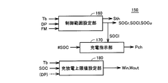
- FIG. 5 shows a more detailed configuration of charge / discharge control unit 150 (FIG. 4).
- charge / discharge control unit 150 includes a control range setting unit 160, a charge instruction unit 170, and a charge / discharge upper limit value setting unit 180.
- Charging / discharging upper limit value setting unit 180 sets charging power upper limit value Win and discharging power upper limit value Wout based at least on battery temperature Tb and estimated SOC value (#SOC).
- SOC estimated value (#SOC) decreases, discharge power upper limit value Wout is set gradually lower.
- SOC estimated value (#SOC) increases, charging power upper limit value Win is set to gradually decrease.
- the power storage device 10 including the secondary battery has a temperature dependency that the internal resistance increases particularly at a low temperature. Further, at a high temperature, it is necessary to prevent the temperature from excessively rising due to further heat generation. For this reason, it is preferable to limit charge / discharge power at low temperatures and high temperatures.
- charging power upper limit value Win and discharging power upper limit value Wout are set in accordance with estimated SOC value (#SOC) and battery temperature Tb.
- the charge / discharge upper limit setting unit 180 may further set the charge power upper limit value Win and the discharge power upper limit value Wout by further reflecting the deterioration parameter DP. Specifically, the charging power upper limit value Win and the discharging power upper limit value Wout can be decreased in accordance with a decrease in the deterioration parameter.
- Control range setting unit 160 sets the SOC control range of power storage device 10 according to battery temperature Tb and deterioration parameter DP.
- the SOC control range is set to have control widths on the upper limit side and the lower limit side with respect to the control center value SOCr.
- SOCl control lower limit value
- SOCu control upper limit value
- Charge instruction unit 170 instructs charging of power storage device 10 when SOC estimated value (#SOC) is lower than the SOC control range by control range setting unit 160, that is, when at least #SOC ⁇ SOCl. That is, Pch> 0 is set. Alternatively, Pch> 0 may be set preliminary at the stage of SOCl ⁇ SOC # ⁇ SOCr. When Pch> 0, the operation of the engine 18 is required. When the engine 18 is stopped, the engine 18 is started. Then, the charging power command value Pch is added to the engine output request.
- the charge / discharge upper limit value setting unit 180 sets the charge power upper limit value Win low as described above. At this time, regenerative power generation by motor generator MG2 is restricted or prohibited, so that overcharging of power storage device 10 is avoided. When regenerative power generation is prohibited, a necessary braking force is generated in the entire hybrid vehicle 5 only by a hydraulic brake mechanism (not shown).
- SOC estimation and setting of charge / discharge power upper limit values Win and Wout based on this are executed.
- the setting of the charge / discharge power upper limit values Win and Wout can reflect the battery temperature and the deterioration parameter that affect the battery performance.
- the SOC control of power storage device 10 is switched as follows between the normal time and the performance time when output power is likely to be reduced.
- SOC control range 151 is set to have control widths on the upper limit side and the lower limit side with respect to control center value SOCr. As described above, charging / discharging of power storage device 10 is controlled such that the estimated SOC value (#SOC) is maintained between control upper limit value SOCu and control lower limit value SOCl.
- the management upper limit value Smax and the management lower limit value Smin are further set for the SOC of the power storage device 10.
- the control upper limit value Smax and the control lower limit value Smin correspond to the charge / discharge limit values on the specification such that the deterioration may rapidly progress when the overcharge or overdischarge further proceeds. Therefore, the SOC control range 151 needs to be set within the range of the management lower limit value Smin to the management upper limit value Smax. That is, control lower limit values SOCl and SOCu are set to have a margin with respect to management lower limit value Smin and management upper limit value Smax.
- Control range setting unit 160 tends to decrease the performance of power storage device 10, from normal SOC control range 151 shown in FIG. 6A to FIG. 6B when the temperature is low and / or deteriorates. It changes to the SOC control range 152 shown.
- the SOC control range 152 (FIG. 6B) is characterized in that the control lower limit SOCl is increased as compared to the SOC control range 151 (FIG. 6A).
- FIG. 7 is a conceptual diagram illustrating setting of the SOC control range with respect to battery temperature Tb.
- control lower limit SOCl is set to S0, which is a default value, at room temperature when T1 ⁇ Tb ⁇ T2. This corresponds to the control lower limit SOCl in the SOC control range 151 in FIG.
- S0 is set in the vicinity of the management lower limit value Smin while ensuring a margin for the management lower limit value Smin.
- the control lower limit SOCl is increased by the correction amount S1.
- the correction amount S1 may be a variable value depending on the battery temperature Tb.
- S1> 0 can be set even when the battery temperature is high (Tb> T2).
- Determination values T1 and T2 can be determined in advance based on the temperature dependence of the performance (for example, internal resistance) of power storage device 10.
- FIG. 8 shows the setting of the correction amount S2 depending on the battery deterioration.
- the deterioration parameter DP decreases as deterioration progresses from when it is new.
- the correction amount S2 0 is set because the influence of deterioration is small.
- a correction amount S2 corresponding to the deterioration parameter DP is set (S2> 0).
- the predetermined level D1 can also be determined in advance by determining the relationship between the deterioration parameter and the battery performance (for example, characteristics relating to the output power that can be secured) by a deterioration test of the power storage device 10 or the like.
- the determination values T1, T2, and D1 are threshold values for determining whether or not the performance of the power storage device 10 is such that the output power is greatly reduced.
- FIG. 9 is a flowchart showing a control processing procedure for realizing charge control of the in-vehicle power storage device in the electric vehicle according to Embodiment 1 of the present invention.
- control device 100 acquires battery data (Tb, Ib, Vb) from monitoring unit 11 in step S100. Then, control device 100 estimates the SOC of power storage device 10 in step S110. That is, the process of step S110 corresponds to the function of the state estimation unit 110 shown in FIG.
- control device 100 sets charging power upper limit value Win and discharging power upper limit value Wout of power storage device 10 based on the estimated SOC value (#SOC) calculated in step S110 and battery temperature Tb.
- the process of step S120 corresponds to the function of the charge / discharge upper limit setting unit 180 of FIG. That is, the setting of charging power upper limit value Win and discharging power upper limit value Wout is the same as that by charging / discharging upper limit value setting unit 180 in FIG.
- step S130 acquires a deterioration parameter DP based on the deterioration diagnosis in step S130.
- the function of step S130 corresponds to the function of the deterioration diagnosis unit 120 shown in FIG. Note that, as described above, the deterioration diagnosis (deterioration parameter DP calculation period) by the deterioration diagnosis unit 120 may not be executed every execution period of the flowchart of FIG. 9. That is, step S130 may be executed by reading out the deterioration parameter DP obtained in the past by the deterioration diagnosis from the memory area.
- step S150 control device 100 sets the SOC control range based on the degradation state (degradation parameter DP) and / or battery temperature (Tb) of power storage device 10.
- the processing in step S150 corresponds to the function of the control range setting unit 160 shown in FIG.
- FIG. 10 is a flowchart for explaining the process of step S150 of FIG. 9 in more detail.
- Control device 100 compares battery temperature Tb with determination value T1 (FIG. 7) in step S155 following steps S151 to S153.
- control device 100 sets correction amount S1 in accordance with battery temperature Tb in step S157. That is, S1> 0 is set.
- the correction amount S1 for the battery temperature Tb is set according to a map created in advance according to the characteristics shown in FIG. As described above, step S155 may be determined as YES even when the battery temperature is high (Tb> T2 (FIG. 7)).
- control device 100 determines the lower limit of the SOC control range according to the sum of default value S0, correction amount S2 set in steps S151 to S152, and correction amount S1 set in steps S155 to S157.
- a value (control lower limit SOCl) is set.
- step S200 controller 100 determines the estimated SOC value (#SOC) obtained in step S110 and the SOC control range set in step S150 (FIGS. 6A and 6B). )) And a charging instruction is generated. That is, the function of step S200 corresponds to the function of charge instruction unit 170 shown in FIG.
- the lower limit value of the SOC control range can be increased more than usual. . Therefore, the SOC lower limit value under charge / discharge control is increased from the normal time.
- output power from the power storage device 10 is secured by avoiding the low SOC region. can do.
- the stored power of power storage device 10 can be used up to the management lower limit region, so that energy efficiency (fuel consumption) can be improved.
- the setting of the SOC control range according to the first embodiment is not limited to the above example as long as the lower limit value of the SOC control range can be increased as a result. That is, the control lower limit SOCl may be directly changed according to FIGS. 7 and 8, or the control lower limit SOCl is incidentally increased by correcting the control center value SOCr according to FIGS. 7 and 8. Also good.
- FIG. 6B shows an example in which the entire SOC control range is shifted upward.
- the control center value SOCr and / or the control upper limit value SOCu are fixed and only the control lower limit value SOCl is changed. Even if it makes it, the same effect can be acquired.
- overall charge / discharge management can be facilitated by shifting the entire SOC control range.
- FIG. 11 is a schematic configuration diagram of a hybrid vehicle 5 shown as a representative example of the electric vehicle according to the second embodiment of the present invention.
- Hybrid vehicle 5 according to the second embodiment is a so-called plug-in type hybrid vehicle that can charge an in-vehicle power storage device with an external power source.
- hybrid vehicle 5 according to the second embodiment has a connector receiving unit 90 for charging power storage device 10 with an external power supply, as compared with the hybrid vehicle according to the first embodiment shown in FIG. 1. And an external charging unit 30. Further, a selection switch 26 provided in the vicinity of the driver's seat is provided for the user to forcibly select a travel mode to be described later.
- charging of power storage device 10 by an external power supply is also referred to as “external charging”, and charging of power storage device 10 by engine 18 and motor generator MG1 while the vehicle is traveling is “internally”. Also referred to as “charging”.
- Connector receiving unit 90 includes a connection detection sensor 90 a for detecting the connection state between connector receiving unit 90 and connector unit 350. Based on the connection signal CON from the connection detection sensor 90a, the control device 100 detects that charging is possible with an external power source.
- the external power supply is typically constituted by a single-phase AC commercial power supply. However, instead of the commercial power source or in addition to the commercial power source, the power of the external power source may be supplied by the power generated by the solar cell panel installed on the roof of the house.
- the connector unit 350 constitutes a coupling mechanism for supplying electric power from an external power source to the hybrid vehicle 5.
- the connector unit 350 is connected to a charging station (not shown) having an external power source via a power line PSL made of a cabtire cable or the like.
- connector part 350 is connected with hybrid vehicle 5 at the time of external charging, and thereby electrically connects an external power supply and external charging part 30 mounted on hybrid vehicle 5.
- the hybrid vehicle 5 is provided with a connector receiving portion 90 for receiving an external power source by being connected to the connector portion 350.
- a configuration in which an external power source and a vehicle are electromagnetically coupled in a non-contact manner to supply electric power specifically, a primary coil is provided on the external power source side, and a vehicle side is provided. You may receive the electric power from an external power supply by the structure which provides a secondary coil and supplies electric power using the mutual inductance between a primary coil and a secondary coil.
- External charging unit 30 is a device for receiving power from an external power source to charge power storage device 10 and is disposed between positive line PL and negative line NL and positive charge line CPL and negative charge line CNL.
- External charging unit 30 includes a current control unit 30 a and a voltage conversion unit 30 b, and converts power from an external power source into power suitable for charging power storage device 10.
- the voltage conversion unit 30b is a device for converting the supply voltage of the external power source into a voltage suitable for charging the power storage device 10, and typically includes a winding transformer having a predetermined transformation ratio, And AC-AC switching regulator. Further, current control unit 30a rectifies the AC voltage after voltage conversion by voltage conversion unit 30b to generate a DC voltage, and controls the charging current supplied to power storage device 10 in accordance with the charging current command from control device 100. To do.
- the current control unit 30a typically includes a single-phase bridge circuit or the like. Note that the external charging unit 30 may be realized by an AC-DC switching regulator or the like instead of the configuration including the current control unit 30a and the voltage conversion unit 30b.
- power storage device 10 can be internally charged while the vehicle is traveling with the electric power generated by motor generator MG1, and after the end of travel, power storage device 10 Can be externally charged.
- a plug-in type electric vehicle it is preferable in terms of energy efficiency to travel while maintaining the engine 18 in a stopped state as much as possible.
- the two travel modes of the EV mode and the HV mode are selectively applied as in JP 2007-62640 A (Patent Document 1).
- 12 and 13 are functional block diagrams illustrating charge / discharge control of the in-vehicle power storage device in the electric vehicle according to the second embodiment of the present invention. 12 and 13 correspond to FIGS. 4 and 5 in the first embodiment, respectively.
- a travel mode selection unit 210 is further provided. Traveling mode selection unit 210 selects one of the EV mode and the HV mode based on the estimated SOC value (#SOC) of power storage device 10 and mode determination value Sth. Traveling mode selection unit 210 generates a traveling mode flag FM indicating which of the EV mode and the HV mode is selected. Traveling mode flag FM is sent to charge / discharge control unit 150 and traveling control unit 200.
- control range setting unit 160 determines the SOC control range (SOCr, SOCu, SOCl) according to travel mode flag FM and battery temperature Tb and / or deterioration parameter DP. Set. The setting of the SOC control range will be described in detail later. Furthermore, the control range setting unit 160 sets the mode determination value Sth according to the battery temperature Tb and / or the deterioration parameter DP.
- running mode selection unit 210 selects the EV mode until SOC estimated value (#SOC) falls below predetermined mode determination value Sth.
- SOC estimated value #SOC
- Sth predetermined mode determination value
- traveling control unit 200 basically stops engine 18 and outputs an output request to motor generators MG1 and MG2 to engine 18 so as to travel only with the driving force from motor generator MG2.
- Determine the output request that is, in the EV mode, when a driving force request such as rapid acceleration is given from the driver in the EV mode, the traveling control unit 200 is given a request that is unrelated to the driving force request such as when the catalyst is warmed up or when the air conditioning is required.
- the engine 18 is started when a special condition is satisfied. That is, in the EV mode, the fuel efficiency of the hybrid vehicle 5 is basically improved by stopping the engine 18. For this reason, in the EV mode, the power generation operation by motor generator MG1, that is, the internal charging is restricted, so the SOC of power storage device 10 decreases monotonously.
- Travel mode selection unit 210 switches the travel mode to the HV mode when the estimated SOC value (#SOC) of power storage device 10 decreases to mode determination value Sth during the EV mode.
- HV mode internal charging by motor generator MG1 is controlled such that the SOC of power storage device 10 is maintained within a certain SOC control range. That is, when internal charging by motor generator MG1 is requested, engine 18 also starts operation. A part of the driving force generated by the operation of the engine 18 may be used for traveling of the hybrid vehicle 5.
- traveling control unit 200 maintains the SOC of power storage device 10 and optimizes the overall fuel consumption and outputs requests to motor generators MG1 and MG2 and to engine 18. Determine the output request.
- traveling mode selection unit 210 automatically selects the traveling mode based on the estimated SOC value (#SOC) of power storage device 10 as described above.
- FIG. 14 shows a typical transition of the SOC of power storage device 10 in the electric vehicle according to the second embodiment.
- power storage device 10 is externally charged to the vicinity of the SOC upper limit value at the start of vehicle travel (time t1).
- the ignition switch is turned on and the traveling of the hybrid vehicle 5 is disclosed, since the SOC estimated value (#SOC) is higher than the mode determination value Sth, the EV mode is selected.
- the SOC of the power storage device 10 gradually decreases due to running in the EV mode.
- the control center value SOCr of the SOC control range is set corresponding to the current SOC estimated value (#SOC). That is, in the EV mode, the SOC control range also decreases as the SOC decreases.
- engine 18 is not started for the purpose of internal charging of power storage device 10.
- the traveling mode shifts from the EV mode to the HV mode.
- the control center value SOCr is set to a constant value for the HV mode.
- the control lower limit SOCl is also kept constant.
- the power storage device 10 When the HV mode is forcibly selected by operating the selection switch 26 during the EV mode (#SOC> Sth), the power storage device 10 is charged / discharged so as to maintain the SOC at that time. Be controlled. That is, the SOC control range is set such that control center value SOCr is fixed to the estimated SOC value (#SOC) when selector switch 26 is operated.
- the driver connects the connector portion 350 (FIG. 10) to the hybrid vehicle 5 to start external charging (time t3). Thereby, the SOC of power storage device 10 begins to rise.
- the SOC control lower limit SOCl is increased when the performance of the power storage device 10 is reduced.
- FIG. 15 is a conceptual diagram illustrating setting of the SOC control range by the control range setting unit 160 (FIG. 13) in the electric vehicle according to the second embodiment.
- the SOC is determined by the control center value SOCr, the predetermined upper limit side control width ⁇ (%), and the lower limit side control width ⁇ (%).
- a control range 151 is defined. This is because, as described with reference to FIG. 14, during the EV mode, the control center value SOCr changes in accordance with the decrease in the SOC.
- an upper limit guard value SOCrmax and a lower limit guard value SOCrmin are set for the control center value SOCr. That is, the range is set to SOCrmin ⁇ SOCr ⁇ SOCrmax through the EV mode and the HV mode.
- Upper limit guard value SOCrmax and lower limit guard value SOCrmin are such that control upper limit value SOCu and control lower limit value SOCl set corresponding to control center value SOCr have a margin with respect to management upper limit value Smax and management lower limit value Smin.
- FIG. 15B shows the SOC control range 151 at normal time, that is, when the power storage device 10 is at normal temperature and is not deteriorated, as in FIG. 6A.
- control range setting unit 160 sets SOC control range 151 to allow control lower limit value SOCl to drop to about default value S0 in the first embodiment.
- FIG. 15 (c) shows the SOC control range 152 when the performance of the power storage device 10 is reduced (during low temperature and / or deterioration), as in FIG. 6 (b).
- Control range setting unit 160 sets SOC control range 152 such that the minimum value of control lower limit SOCl is higher than normal.
- the lower limit value (SOCl) of the normal SOC control range 151 is equivalent to that in FIG. 6A, and the lower limit value of the SOC control range 152 when the performance of the power storage device 10 is degraded. (SOCl) is equivalent to FIG.
- the upper limit guard value SOCrmax of the control center value is constant between the normal time (FIG. 15B) and the performance degradation time (FIG. 15C).
- FIG. 16 shows a processing procedure of charge / discharge control of power storage device 10 in the electric vehicle according to the second embodiment of the present invention.
- control device 100 performs battery data detection, SOC estimation, charge / discharge power upper limit (Win, Wout) setting, and deterioration parameter (DP) through steps S100 to S130 similar to FIG. Execute the acquisition. Furthermore, the control device 100 determines the travel mode in step S140. As a result, the travel mode is selected as either the HV mode or the EV mode.
- the process of step S140 corresponds to the function of the travel mode selection unit 210 shown in FIG.
- control device 100 sets the SOC control range in step S150.
- FIG. 17 is a flowchart showing in detail the process of step S150 of FIG. 16 for explaining the SOC control range according to the second embodiment.
- control device 100 sets correction amount S2 corresponding to deterioration parameter DP and correction amount S1 corresponding to battery temperature Tb through steps S151 to S157 similar to FIG.
- control device 100 sets lower limit guard value SOCrmin of the control center value as the sum of default value SO #, correction amount S1, and correction amount S2.
- Default value SO # corresponds to lower limit guard value SOCrmin (for example, S0 + ⁇ ) in FIG.
- step S170 the control device 100 determines whether or not the traveling mode is the EV mode.
- control device 100 compares the estimated SOC value (#SOC) with lower limit guard value SOCrmin in step S172.
- #SOC is higher than lower limit guard value SOCrmin (YES in S170)
- the control center value SOCr is set so as to change according to the estimated SOC value (#SOC) after guarding so as not to fall below the lower limit guard value SOCrmin.
- the control lower limit SOCl also changes within a range that does not fall below the default value S0.
- control device 100 sets control center value SOCr in accordance with lower limit guard value SOCrmin obtained in step S165 in step S280.
- the control center value SOCr SOCrmin may be set, but a value obtained by adding a predetermined margin to the lower limit guard value SOCrmin may be used as the control center value SOCr.
- the control center value SOCr is constant regardless of the change in the estimated SOC value.
- the control center value SOCr is fixed to the estimated SOC value (#SOC) when the selection switch 26 is operated. Is done.
- control device 100 controls control upper limit value SOCu and control lower limit value SOCl so as to ensure predetermined control widths ⁇ and ⁇ with respect to control center value SOCr set in step S174, S176, or S180. To decide.
- the electric vehicle according to the second embodiment can externally charge the in-vehicle power storage device, and travels with the EV mode and the HV mode selected. Also in the electric vehicle according to the second embodiment, when the performance of power storage device 10 is reduced (during low temperature and / or progressing deterioration), the lower limit value of the SOC control range is set to the normal value as in the first embodiment. Than can rise.
- the lower limit value of the SOC control range is set according to both the temperature and the degradation state of power storage device 10, but the SOC control is performed according to only one of the temperature and the degradation state.
- a lower limit value of the range may be set. In this case, one of the correction amounts S1 and S2 is fixed to zero.
- the control width ( ⁇ , ⁇ ) is provided around the control center value SOCr, but other setting methods can be applied.
- any mode can be applied as long as the lower limit value of the SOC control range can be increased more than the normal time when the performance of the power storage device 10 is lowered.
- the motor generator MG1 operates as a motor so as to crank the engine 18 using the motor generator MG1.
- the MG1 rotation speed changes from negative to positive.
- motor generator MG1 generates a positive torque for motoring
- motor generator MG1 generates power when MG1 rotational speed is negative
- motor generator MG1 consumes power when MG1 rotational speed is positive.
- the generated power and consumed power of motor generator MG1 at the time of engine start are input / output to / from power storage device 10.
- the power required for starting the stopped engine 18 varies depending on the vehicle state (typically, the vehicle speed). And if the electrical storage apparatus 10 cannot output this required electric power reliably, it will become difficult to start the engine 18 reliably. On the other hand, in order to charge power storage device 10 while traveling, engine 18 needs to be operated.
- the power storage device 10 has enough power to start the stopped engine 18 or restart the engine 18 after it is stopped. It is preferable to maintain.
- the charge control of power storage device 10 for ensuring engine startability is further executed. .
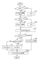
- FIG. 20 is a flowchart for explaining the characteristics of charge / discharge control of the in-vehicle power storage device of the electric vehicle according to the third embodiment.
- step S200 charging instruction in the flowcharts of FIG. 9 (Embodiment 1) and FIG. 16 (Embodiment 2) follows the flowchart of FIG. Executed. Since other control operations may be the same as those in the first or second embodiment, detailed description will not be repeated.
- control device 100 determines whether or not the performance degradation (low temperature and / or degradation) of power storage device 10 has occurred as described in the first and second embodiments. judge. That is, in FIG. 10 or FIG. 17, when at least one of steps S151 and S155 is determined as YES, step S210 is determined as YES. Otherwise, step S210 is determined as NO.
- control device 100 estimates the power value required to start engine 18 in step S220, and determines based on this estimation result.
- Determination value W1 is set so as to have a margin with respect to the output power from power storage device 10 that is required to start engine 18 or restart it after stopping.
- the electric power required for starting the engine varies depending on the vehicle speed of the hybrid vehicle 5. Further, at low temperatures, there is a concern that the electric power required for starting the engine may increase due to a decrease in the viscosity of the lubricating oil. Therefore, the determination value W1 is preferably set variably according to the vehicle state such as the vehicle speed and temperature.
- step S230 the control device 100 compares the current discharge power upper limit value Wout with the determination value W1. As described above, the current SOC estimated value (#SOC) and the battery temperature Tb are reflected in the discharge power upper limit Wout.
- control device 100 proceeds to step S250 to make a request for charging power storage device 10 regardless of the SOC. It occurs forcibly. That is, Pch> 0 is set.
- control device 100 allows discharge to control lower limit SOCl in step S240.
- whether or not charging is necessary is determined according to the estimated SOC value (#SOC).
- the SOC control range set according to FIG. 6B or 15C in the first or second embodiment and shifted to the upper limit side than the normal time is applied. Has been.
- control device 100 performs normal charge / discharge control in step S260. Specifically, it is determined whether or not the power storage device 10 needs to be charged according to the normal control lower limit SOCl (default value) set according to FIG. 6A or 15B in the first or second embodiment. Is done.
- the output from the power storage device 10 can be performed by shifting the SOC control range when the performance of the power storage device 10 is lowered, as in the first and second embodiments. A decrease in drivability of the hybrid vehicle 5 due to power shortage can be avoided. Further, in the third embodiment, charging of power storage device 10 is controlled so that discharge power upper limit value Wout of power storage device 10 does not fall below the output power required for engine start, which is necessary depending on the vehicle state and user operation. The starting of the engine 18 can now be realized with certainty. As a result, it is possible to more reliably avoid the drivability reduction of the hybrid vehicle 5 due to the shortage of output power from the power storage device 10.
- the present invention can be applied if a power generation mechanism for charging a power storage device mounted on an electric vehicle while traveling is described.
- the present invention can be applied to a hybrid vehicle having a hybrid configuration different from those shown in FIGS. 1 and 11 (for example, a so-called series hybrid configuration or an electric distribution type hybrid configuration) and a fuel cell vehicle.
- the present invention can be applied to an electric vehicle equipped with a vehicle-mounted power storage device and a power generation mechanism for generating charging power for the vehicle-mounted power storage device while the vehicle is traveling.
Priority Applications (3)
| Application Number | Priority Date | Filing Date | Title |
|---|---|---|---|
| CN201180024943.2A CN102905949B (zh) | 2010-05-20 | 2011-05-16 | 电动车辆及其控制方法 |
| US13/699,049 US9327591B2 (en) | 2010-05-20 | 2011-05-16 | Electrically powered vehicle and method for controlling same |
| EP11783480.4A EP2572951B1 (de) | 2010-05-20 | 2011-05-16 | Elektrisch angetriebenes fahrzeug und steuerverfahren dafür |
Applications Claiming Priority (2)
| Application Number | Priority Date | Filing Date | Title |
|---|---|---|---|
| JP2010-116142 | 2010-05-20 | ||
| JP2010116142A JP5730501B2 (ja) | 2010-05-20 | 2010-05-20 | 電動車両およびその制御方法 |
Publications (1)
| Publication Number | Publication Date |
|---|---|
| WO2011145546A1 true WO2011145546A1 (ja) | 2011-11-24 |
Family
ID=44991649
Family Applications (1)
| Application Number | Title | Priority Date | Filing Date |
|---|---|---|---|
| PCT/JP2011/061154 WO2011145546A1 (ja) | 2010-05-20 | 2011-05-16 | 電動車両およびその制御方法 |
Country Status (5)
| Country | Link |
|---|---|
| US (1) | US9327591B2 (de) |
| EP (1) | EP2572951B1 (de) |
| JP (2) | JP5730501B2 (de) |
| CN (1) | CN102905949B (de) |
| WO (1) | WO2011145546A1 (de) |
Cited By (5)
| Publication number | Priority date | Publication date | Assignee | Title |
|---|---|---|---|---|
| CN103770786A (zh) * | 2012-10-19 | 2014-05-07 | 福特全球技术公司 | 控制车辆的方法 |
| JP2014094724A (ja) * | 2012-11-12 | 2014-05-22 | Honda Motor Co Ltd | ハイブリッド車両 |
| JP2016127770A (ja) * | 2015-01-08 | 2016-07-11 | トヨタ自動車株式会社 | 電源装置 |
| CN109986996A (zh) * | 2017-12-28 | 2019-07-09 | 丰田自动车株式会社 | 汽车 |
| CN110091860A (zh) * | 2018-01-30 | 2019-08-06 | 丰田自动车株式会社 | 电动车辆以及电动车辆的控制方法 |
Families Citing this family (53)
| Publication number | Priority date | Publication date | Assignee | Title |
|---|---|---|---|---|
| JPH06157185A (ja) * | 1992-09-25 | 1994-06-03 | Furukawa Electric Co Ltd:The | 化合物半導体単結晶の成長方法 |
| US9007002B2 (en) * | 2010-06-15 | 2015-04-14 | Ihi Corporation | Device and method for power-saving driving of device having same load pattern |
| JP6028328B2 (ja) * | 2011-12-22 | 2016-11-16 | トヨタ自動車株式会社 | ハイブリッド車両 |
| JP5966376B2 (ja) * | 2012-01-20 | 2016-08-10 | トヨタ自動車株式会社 | ハイブリッド車両の制御装置 |
| JP5919857B2 (ja) * | 2012-02-03 | 2016-05-18 | スズキ株式会社 | 充放電制御装置 |
| JP2016010981A (ja) * | 2012-09-10 | 2016-01-21 | 本田技研工業株式会社 | ハイブリッド車両の制御装置 |
| JP5888215B2 (ja) * | 2012-12-04 | 2016-03-16 | 株式会社デンソー | 電池システム |
| JP6127550B2 (ja) * | 2013-02-05 | 2017-05-17 | コベルコ建機株式会社 | 建設機械 |
| US9878635B1 (en) * | 2013-02-13 | 2018-01-30 | University Of Maryland | Powertrain system in plug-in electric vehicles |
| JP5803965B2 (ja) * | 2013-03-25 | 2015-11-04 | トヨタ自動車株式会社 | 車両 |
| KR101490922B1 (ko) * | 2013-06-18 | 2015-02-06 | 현대자동차 주식회사 | 하이브리드 자동차의 배터리 방전 파워 제한시 주행모드 변환 방법 및 시스템 |
| JP2015011576A (ja) * | 2013-06-28 | 2015-01-19 | 株式会社東芝 | 蓄電池駆動車両の運行システム |
| KR101481282B1 (ko) * | 2013-06-28 | 2015-01-09 | 현대자동차주식회사 | 하이브리드차량의 주행모드 제어방법 |
| KR101481283B1 (ko) * | 2013-06-28 | 2015-01-09 | 현대자동차주식회사 | 하이브리드차량의 운전제어방법 |
| KR101575409B1 (ko) * | 2013-10-07 | 2015-12-07 | 현대자동차주식회사 | 자동차의 회생제동허용량 결정 시스템 및 방법 |
| FR3018360B1 (fr) * | 2014-03-07 | 2016-02-26 | Renault Sas | Methode d'estimation d'un etat de charge d'une batterie comportant plusieurs cellules presentant une plage d'utilisation d'etat de charge variable |
| JP6361299B2 (ja) * | 2014-06-09 | 2018-07-25 | トヨタ自動車株式会社 | ハイブリッド車両 |
| KR101601474B1 (ko) * | 2014-08-25 | 2016-03-21 | 현대자동차주식회사 | 차량 주행 가능 거리 유지 시스템 및 그 방법 |
| JP6439322B2 (ja) * | 2014-08-27 | 2018-12-19 | 三菱自動車工業株式会社 | ハイブリッド車両の回生制御装置 |
| JP6321513B2 (ja) * | 2014-09-29 | 2018-05-09 | 株式会社Subaru | 車両の制御装置及び車両 |
| JP6295942B2 (ja) * | 2014-12-15 | 2018-03-20 | トヨタ自動車株式会社 | 充電装置 |
| FR3030768B1 (fr) * | 2014-12-22 | 2018-04-06 | Renault S.A.S | Procede de gestion d'energie d'une batterie de traction d'un vehicule hybride rechargeable. |
| JP6213511B2 (ja) | 2015-03-25 | 2017-10-18 | トヨタ自動車株式会社 | 電動車両及びその制御方法 |
| FR3041914B1 (fr) * | 2015-10-05 | 2018-07-13 | Renault S.A.S. | Procede de determination des plages d'utilisation d'une batterie de traction |
| JP6387940B2 (ja) * | 2015-10-22 | 2018-09-12 | 株式会社オートネットワーク技術研究所 | 車載用電源装置 |
| CN107825994A (zh) * | 2015-11-30 | 2018-03-23 | 于在水 | 电动车辆控制方法 |
| JP6701699B2 (ja) * | 2015-12-04 | 2020-05-27 | いすゞ自動車株式会社 | バッテリーの制御システム、ハイブリッド車両及びバッテリーの制御方法 |
| JP6391604B2 (ja) * | 2016-01-26 | 2018-09-19 | 本田技研工業株式会社 | 電力供給システム |
| JP6661416B2 (ja) * | 2016-03-04 | 2020-03-11 | 株式会社東芝 | ハイブリッド電気機関車 |
| JP2017166463A (ja) * | 2016-03-18 | 2017-09-21 | トヨタ自動車株式会社 | エンジン始動装置 |
| JP6361684B2 (ja) * | 2016-04-15 | 2018-07-25 | トヨタ自動車株式会社 | ハイブリッド車両の制御装置 |
| US10899247B2 (en) * | 2016-06-08 | 2021-01-26 | Ford Global Technologies, Llc | System and method for online vehicle battery capacity diagnosis |
| JP6768813B2 (ja) * | 2016-09-12 | 2020-10-14 | 株式会社東芝 | 車両 |
| JP6455497B2 (ja) * | 2016-11-16 | 2019-01-23 | トヨタ自動車株式会社 | 車両の電池システム及びその制御方法 |
| JP6583298B2 (ja) * | 2017-01-24 | 2019-10-02 | トヨタ自動車株式会社 | 電動車両 |
| JP6772947B2 (ja) * | 2017-04-27 | 2020-10-21 | トヨタ自動車株式会社 | ハイブリッド自動車 |
| JP7235409B2 (ja) * | 2017-06-16 | 2023-03-08 | 株式会社半導体エネルギー研究所 | 充電制御システム及び充電制御方法 |
| DE102017210430A1 (de) | 2017-06-21 | 2018-12-27 | Bayerische Motoren Werke Aktiengesellschaft | Energieversorgungseinrichtung für ein Kraftfahrzeug |
| KR20190010045A (ko) * | 2017-07-20 | 2019-01-30 | 현대자동차주식회사 | 친환경 차량의 충전 제어 장치, 그를 포함한 시스템 및 그 방법 |
| JPWO2019069458A1 (ja) * | 2017-10-06 | 2020-02-27 | 株式会社東芝 | ハイブリッド車両 |
| JP6888512B2 (ja) * | 2017-10-16 | 2021-06-16 | トヨタ自動車株式会社 | ハイブリッド自動車 |
| CN108001259B (zh) * | 2017-11-02 | 2021-04-02 | 合肥国轩高科动力能源有限公司 | 一种电动汽车双动力系统故障检测方法 |
| JP7047408B2 (ja) * | 2018-01-30 | 2022-04-05 | トヨタ自動車株式会社 | 電動車両 |
| JP2019152551A (ja) * | 2018-03-05 | 2019-09-12 | 株式会社デンソー | 電池劣化判定装置 |
| JP7048364B2 (ja) * | 2018-03-14 | 2022-04-05 | トヨタ自動車株式会社 | ハイブリッド車両および、その制御方法 |
| EP3767778B1 (de) * | 2018-03-15 | 2023-10-04 | Yamaha Hatsudoki Kabushiki Kaisha | Batteriesteuerungssystem für nickel-metallhydrid-akkumulator |
| JP6744350B2 (ja) | 2018-03-19 | 2020-08-19 | 本田技研工業株式会社 | 車両 |
| CN112334374B (zh) | 2018-06-22 | 2023-07-28 | 三菱电机株式会社 | 驱动控制装置及铁路车辆用驱动装置 |
| JP7103151B2 (ja) * | 2018-10-17 | 2022-07-20 | トヨタ自動車株式会社 | 燃料電池車両および燃料電池車両の制御方法 |
| KR20200085150A (ko) * | 2019-01-04 | 2020-07-14 | 주식회사 엘지화학 | 배터리 관리 방법, 배터리 장치, 및 배터리를 포함하는 자동차 |
| EP3798047A1 (de) * | 2019-09-24 | 2021-03-31 | Volvo Car Corporation | Erleichterung der batteriewartung |
| JP7432064B2 (ja) | 2021-09-08 | 2024-02-15 | 寧徳時代新能源科技股▲分▼有限公司 | 動力電池を充電する方法及び電池管理システム |
| JP2023066618A (ja) * | 2021-10-29 | 2023-05-16 | 株式会社トランストロン | 制御装置、制御方法、および制御プログラム |
Citations (8)
| Publication number | Priority date | Publication date | Assignee | Title |
|---|---|---|---|---|
| JP2000030753A (ja) * | 1998-07-15 | 2000-01-28 | Nissan Motor Co Ltd | ハイブリッド車両用電池の制御装置 |
| JP2004271410A (ja) * | 2003-03-11 | 2004-09-30 | Hitachi Ltd | 電気車のバッテリ制御装置 |
| JP2007062640A (ja) | 2005-09-01 | 2007-03-15 | Toyota Motor Corp | ハイブリッド自動車 |
| JP2007195312A (ja) | 2006-01-18 | 2007-08-02 | Toyota Motor Corp | 二次電池の寿命推定装置 |
| JP2008094178A (ja) * | 2006-10-10 | 2008-04-24 | Toyota Motor Corp | 車両の制御装置、制御方法、その方法を実現するプログラムおよびそのプログラムを記録した記録媒体 |
| JP2008308122A (ja) * | 2007-06-18 | 2008-12-25 | Mazda Motor Corp | 車両用バッテリの制御装置 |
| JP2009113695A (ja) * | 2007-11-08 | 2009-05-28 | Toyota Motor Corp | ハイブリッド車およびその制御方法 |
| JP2009292179A (ja) * | 2008-06-02 | 2009-12-17 | Toyota Motor Corp | ハイブリッド自動車およびその制御方法 |
Family Cites Families (7)
| Publication number | Priority date | Publication date | Assignee | Title |
|---|---|---|---|---|
| JP2007186038A (ja) | 2006-01-12 | 2007-07-26 | Nissan Motor Co Ltd | モータ駆動車両の制御装置 |
| JP4538418B2 (ja) * | 2006-02-15 | 2010-09-08 | トヨタ自動車株式会社 | 二次電池の充放電制御装置 |
| JP4155321B2 (ja) * | 2006-09-25 | 2008-09-24 | トヨタ自動車株式会社 | ハイブリッド車両の表示装置、ハイブリッド車両、およびハイブリッド車両の表示方法 |
| JP2008087516A (ja) * | 2006-09-29 | 2008-04-17 | Toyota Motor Corp | ハイブリッド車両およびハイブリッド車両の走行制御方法 |
| JP4274257B2 (ja) * | 2007-02-20 | 2009-06-03 | トヨタ自動車株式会社 | ハイブリッド車両 |
| JP4450100B2 (ja) * | 2008-09-19 | 2010-04-14 | トヨタ自動車株式会社 | 動力出力装置、それを備えた車両および動力出力装置の制御方法 |
| JP4572979B2 (ja) | 2008-10-21 | 2010-11-04 | トヨタ自動車株式会社 | 電源システムおよびそれを備えた車両、ならびに電源システムの制御方法 |
-
2010
- 2010-05-20 JP JP2010116142A patent/JP5730501B2/ja active Active
-
2011
- 2011-05-16 CN CN201180024943.2A patent/CN102905949B/zh active Active
- 2011-05-16 WO PCT/JP2011/061154 patent/WO2011145546A1/ja active Application Filing
- 2011-05-16 US US13/699,049 patent/US9327591B2/en active Active
- 2011-05-16 EP EP11783480.4A patent/EP2572951B1/de active Active
-
2013
- 2013-06-20 JP JP2013129786A patent/JP2013227017A/ja active Pending
Patent Citations (8)
| Publication number | Priority date | Publication date | Assignee | Title |
|---|---|---|---|---|
| JP2000030753A (ja) * | 1998-07-15 | 2000-01-28 | Nissan Motor Co Ltd | ハイブリッド車両用電池の制御装置 |
| JP2004271410A (ja) * | 2003-03-11 | 2004-09-30 | Hitachi Ltd | 電気車のバッテリ制御装置 |
| JP2007062640A (ja) | 2005-09-01 | 2007-03-15 | Toyota Motor Corp | ハイブリッド自動車 |
| JP2007195312A (ja) | 2006-01-18 | 2007-08-02 | Toyota Motor Corp | 二次電池の寿命推定装置 |
| JP2008094178A (ja) * | 2006-10-10 | 2008-04-24 | Toyota Motor Corp | 車両の制御装置、制御方法、その方法を実現するプログラムおよびそのプログラムを記録した記録媒体 |
| JP2008308122A (ja) * | 2007-06-18 | 2008-12-25 | Mazda Motor Corp | 車両用バッテリの制御装置 |
| JP2009113695A (ja) * | 2007-11-08 | 2009-05-28 | Toyota Motor Corp | ハイブリッド車およびその制御方法 |
| JP2009292179A (ja) * | 2008-06-02 | 2009-12-17 | Toyota Motor Corp | ハイブリッド自動車およびその制御方法 |
Cited By (6)
| Publication number | Priority date | Publication date | Assignee | Title |
|---|---|---|---|---|
| CN103770786A (zh) * | 2012-10-19 | 2014-05-07 | 福特全球技术公司 | 控制车辆的方法 |
| CN103770786B (zh) * | 2012-10-19 | 2016-12-14 | 福特全球技术公司 | 控制车辆的方法 |
| JP2014094724A (ja) * | 2012-11-12 | 2014-05-22 | Honda Motor Co Ltd | ハイブリッド車両 |
| JP2016127770A (ja) * | 2015-01-08 | 2016-07-11 | トヨタ自動車株式会社 | 電源装置 |
| CN109986996A (zh) * | 2017-12-28 | 2019-07-09 | 丰田自动车株式会社 | 汽车 |
| CN110091860A (zh) * | 2018-01-30 | 2019-08-06 | 丰田自动车株式会社 | 电动车辆以及电动车辆的控制方法 |
Also Published As
| Publication number | Publication date |
|---|---|
| EP2572951A4 (de) | 2018-04-04 |
| US20130062941A1 (en) | 2013-03-14 |
| JP2013227017A (ja) | 2013-11-07 |
| CN102905949B (zh) | 2015-09-16 |
| EP2572951B1 (de) | 2020-03-25 |
| CN102905949A (zh) | 2013-01-30 |
| US9327591B2 (en) | 2016-05-03 |
| JP2011240863A (ja) | 2011-12-01 |
| JP5730501B2 (ja) | 2015-06-10 |
| EP2572951A1 (de) | 2013-03-27 |
Similar Documents
| Publication | Publication Date | Title |
|---|---|---|
| JP5730501B2 (ja) | 電動車両およびその制御方法 | |
| JP5418676B2 (ja) | 電動車両およびその制御方法 | |
| JP5772952B2 (ja) | 電動車両および電動車両の制御方法 | |
| JP5716693B2 (ja) | ハイブリッド車両 | |
| JP5278614B2 (ja) | ハイブリッド車両およびその制御方法 | |
| EP2083156B1 (de) | Hybridfahrzeug und steuerverfahren dafür | |
| JP5218661B2 (ja) | 内燃機関の制御装置および内燃機関の制御方法 | |
| JP2008087516A (ja) | ハイブリッド車両およびハイブリッド車両の走行制御方法 | |
| JP2011093335A (ja) | ハイブリッド車両の制御装置 | |
| JP5267734B2 (ja) | 電動車両およびその制御方法 | |
| JP6028328B2 (ja) | ハイブリッド車両 | |
| JP2010241396A (ja) | ハイブリッド車両の電源システム | |
| JP2010083394A (ja) | ハイブリッド車両 | |
| JP4321641B2 (ja) | ハイブリッド車両、ハイブリッド車両の制御方法およびその制御方法をコンピュータに実行させるためのプログラムを記録したコンピュータ読取可 | |
| JP2013154720A (ja) | ハイブリッド車両 | |
| JP2010064499A (ja) | ハイブリッド車両 | |
| JP5733198B2 (ja) | ハイブリッド車両 | |
| JP2013154718A (ja) | ハイブリッド車両 |
Legal Events
| Date | Code | Title | Description |
|---|---|---|---|
| WWE | Wipo information: entry into national phase |
Ref document number: 201180024943.2 Country of ref document: CN |
|
| 121 | Ep: the epo has been informed by wipo that ep was designated in this application |
Ref document number: 11783480 Country of ref document: EP Kind code of ref document: A1 |
|
| DPE1 | Request for preliminary examination filed after expiration of 19th month from priority date (pct application filed from 20040101) | ||
| NENP | Non-entry into the national phase |
Ref country code: DE |
|
| WWE | Wipo information: entry into national phase |
Ref document number: 13699049 Country of ref document: US |
|
| WWE | Wipo information: entry into national phase |
Ref document number: 2011783480 Country of ref document: EP |