WO2011145334A1 - Dispositif de commande sans capteur de rotation - Google Patents
Dispositif de commande sans capteur de rotation Download PDFInfo
- Publication number
- WO2011145334A1 WO2011145334A1 PCT/JP2011/002738 JP2011002738W WO2011145334A1 WO 2011145334 A1 WO2011145334 A1 WO 2011145334A1 JP 2011002738 W JP2011002738 W JP 2011002738W WO 2011145334 A1 WO2011145334 A1 WO 2011145334A1
- Authority
- WO
- WIPO (PCT)
- Prior art keywords
- inverter
- voltage
- current
- angular velocity
- control unit
- Prior art date
Links
Images


Classifications
-
- H—ELECTRICITY
- H02—GENERATION; CONVERSION OR DISTRIBUTION OF ELECTRIC POWER
- H02P—CONTROL OR REGULATION OF ELECTRIC MOTORS, ELECTRIC GENERATORS OR DYNAMO-ELECTRIC CONVERTERS; CONTROLLING TRANSFORMERS, REACTORS OR CHOKE COILS
- H02P6/00—Arrangements for controlling synchronous motors or other dynamo-electric motors using electronic commutation dependent on the rotor position; Electronic commutators therefor
- H02P6/14—Electronic commutators
- H02P6/16—Circuit arrangements for detecting position
- H02P6/18—Circuit arrangements for detecting position without separate position detecting elements
- H02P6/182—Circuit arrangements for detecting position without separate position detecting elements using back-emf in windings
-
- H—ELECTRICITY
- H02—GENERATION; CONVERSION OR DISTRIBUTION OF ELECTRIC POWER
- H02P—CONTROL OR REGULATION OF ELECTRIC MOTORS, ELECTRIC GENERATORS OR DYNAMO-ELECTRIC CONVERTERS; CONTROLLING TRANSFORMERS, REACTORS OR CHOKE COILS
- H02P21/00—Arrangements or methods for the control of electric machines by vector control, e.g. by control of field orientation
- H02P21/24—Vector control not involving the use of rotor position or rotor speed sensors
-
- H—ELECTRICITY
- H02—GENERATION; CONVERSION OR DISTRIBUTION OF ELECTRIC POWER
- H02P—CONTROL OR REGULATION OF ELECTRIC MOTORS, ELECTRIC GENERATORS OR DYNAMO-ELECTRIC CONVERTERS; CONTROLLING TRANSFORMERS, REACTORS OR CHOKE COILS
- H02P21/00—Arrangements or methods for the control of electric machines by vector control, e.g. by control of field orientation
- H02P21/34—Arrangements for starting
-
- H—ELECTRICITY
- H02—GENERATION; CONVERSION OR DISTRIBUTION OF ELECTRIC POWER
- H02P—CONTROL OR REGULATION OF ELECTRIC MOTORS, ELECTRIC GENERATORS OR DYNAMO-ELECTRIC CONVERTERS; CONTROLLING TRANSFORMERS, REACTORS OR CHOKE COILS
- H02P27/00—Arrangements or methods for the control of AC motors characterised by the kind of supply voltage
- H02P27/04—Arrangements or methods for the control of AC motors characterised by the kind of supply voltage using variable-frequency supply voltage, e.g. inverter or converter supply voltage
- H02P27/06—Arrangements or methods for the control of AC motors characterised by the kind of supply voltage using variable-frequency supply voltage, e.g. inverter or converter supply voltage using dc to ac converters or inverters
- H02P27/08—Arrangements or methods for the control of AC motors characterised by the kind of supply voltage using variable-frequency supply voltage, e.g. inverter or converter supply voltage using dc to ac converters or inverters with pulse width modulation
-
- H—ELECTRICITY
- H02—GENERATION; CONVERSION OR DISTRIBUTION OF ELECTRIC POWER
- H02P—CONTROL OR REGULATION OF ELECTRIC MOTORS, ELECTRIC GENERATORS OR DYNAMO-ELECTRIC CONVERTERS; CONTROLLING TRANSFORMERS, REACTORS OR CHOKE COILS
- H02P6/00—Arrangements for controlling synchronous motors or other dynamo-electric motors using electronic commutation dependent on the rotor position; Electronic commutators therefor
- H02P6/20—Arrangements for starting
-
- H—ELECTRICITY
- H02—GENERATION; CONVERSION OR DISTRIBUTION OF ELECTRIC POWER
- H02P—CONTROL OR REGULATION OF ELECTRIC MOTORS, ELECTRIC GENERATORS OR DYNAMO-ELECTRIC CONVERTERS; CONTROLLING TRANSFORMERS, REACTORS OR CHOKE COILS
- H02P2203/00—Indexing scheme relating to controlling arrangements characterised by the means for detecting the position of the rotor
- H02P2203/01—Motor rotor position determination based on the detected or calculated phase inductance, e.g. for a Switched Reluctance Motor
Definitions
- Embodiments described herein relate generally to a rotation sensorless control device for a synchronous motor.
- the free-run state is a state in which the notch command from the cab is neutral (0) and the inertial running is performed with all the switching element gate commands of the inverter driving the motor being off.
- a method using an induced voltage that is, a method using zero current control, a method using a short circuit current, and the like have been proposed.
- a method using an inductance has been proposed.
- a method for selecting an appropriate method according to the motor angular velocity from both of them has also been proposed. By these methods, it is possible to start from a free-run state.
- JP 2008-017690 A Japanese Patent No. 3636340 Japanese Unexamined Patent Publication No. 7-177788 Japanese Patent No. 3486326
- the high voltage region the region where the no-load induced voltage is higher than the voltage on the DC side of the inverter (hereinafter this region is called the high voltage region).
- the present invention is a rotation sensorless control of a synchronous motor, and an object thereof is to realize restart from free run in all regions including a region where no-load induced voltage is larger than the DC side voltage of an inverter. To do.
- the rotation sensorless control apparatus has the following configuration. That is, A rotation sensorless control device for controlling an inverter that drives a synchronous machine, A phase angle / angular velocity estimator that estimates the rotor phase angle and angular velocity using both the inductance and the induced voltage of the synchronous machine, and A control unit that generates a voltage command value and controls an output current of the inverter, using PWM that selects only a non-zero voltage vector at the time of starting the inverter and the motor from a free run; The phase angle / angular velocity estimation unit estimates the rotational phase angle / angular velocity using the voltage command value and the inverter output current.
- determination method The block diagram which shows the structure which judges the necessity of NS discrimination
- the embodiment of the present invention relates to a restart method from free run in rotation sensorless control.
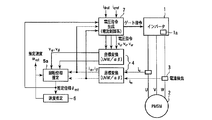
- FIG. 1 is a block diagram showing a configuration of a first embodiment of a rotation sensorless control apparatus according to the present invention.
- the inverter 1 receives a gate command for driving the inverter 1 and converts AC / DC power to each other by switching ON / OFF of a main circuit switching element built in the inverter 1.
- the motor 2 is a PMSM (Permanent Magnet Synchronous ⁇ Motor), and a magnetic field is generated by a three-phase alternating current flowing in each excitation phase, and torque is generated by magnetic interaction with the rotor.
- the current detection unit 3 detects a two-phase or three-phase current response value in the three-phase alternating current flowing through the PMSM.
- FIG. 1 shows a configuration for detecting a two-phase current.
- the coordinate conversion means 4 performs coordinate conversion of the u, v, w three-phase fixed coordinate system and the ⁇ axis fixed coordinate system of the motor 3.
- the ⁇ axis indicates the u-phase winding axis of the motor 3, and the ⁇ axis is an axis orthogonal to the ⁇ axis.
- the rotation phase estimation unit 5a estimates the rotation phase angle of the motor 3 from the current response values i ⁇ and i ⁇ detected by the current detection unit (details will be described later).
- the angular velocity estimation unit 6 estimates the angular velocity ⁇ est from the phase ⁇ est estimated by the rotational phase estimation unit 5. For example, it means for calculating based on the time derivative of the estimated phase theta est, and the like means for estimating the angular velocity omega est a PLL (Phase Locked Loop) The difference between the phase that calculates an estimated phase theta est as input.
- PLL Phase Locked Loop
- the voltage command generator 7 determines and outputs a gate signal using the current response values i ⁇ and i ⁇ and the current command values i dref and i qref obtained from the current detector 3 via the coordinate conversion means 4 ( Details will be described later).
- the phase and angular velocity are estimated using a fixed coordinate system, but may be estimated using a rotating coordinate system.
- v d and v q are dq axis armature voltages
- i d and i q are dq axis armature currents
- R m is winding resistance
- L d and L q are dq axis inductances
- ⁇ is a dq axis rotor angular velocity
- ⁇ f is a magnetic flux coefficient
- the inductances L d and L q are values specific to the motor.
- Equation (2) the voltage equation of Equation (1) is expressed by Equation (2).
- v ⁇ and v ⁇ are ⁇ - ⁇ -axis armature voltages
- i ⁇ and i ⁇ are ⁇ - ⁇ -axis armature currents.
- the expanded induced voltage is expressed by Expression (4).
- the phase ⁇ can be calculated by the equation (5).
- phase estimation may be another estimation method as long as it uses both the induced voltage and the inductance.
- E 0x has only a differential term of the q-axis current when the angular velocity ⁇ is small.
- E 0x becomes small, an error becomes large when calculating the phase ⁇ in the equation (5) and cannot be estimated accurately.
- the current differential term is increased, the phase can be estimated accurately from low speed to high speed. It becomes like this. That is, for example, in the first equation of equation (4), if the current differential term pi q is large, E 0x increases, and the estimation accuracy of the phase ⁇ shown in equation (5) increases, and the phase is accurately obtained from low to high speed. Can be estimated.
- a current follow-up type PWM that directly generates a PWM signal so that the instantaneous value of the inverter output current follows the reference value is used.
- An example of the control operation of the current tracking type PWM is described in, for example, Japanese Patent No. 3267528.
- the current tracking type PWM only the non-zero voltage vector is selected as the voltage vector in this embodiment in order to increase the current differential term as described above so that the phase can be estimated with high accuracy.
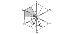
- FIG. 2 shows the output voltage vectors V 1 to V 6 (voltage vector command) of the inverter 1.
- the inverter 1 can take V 0 and V 7 as the output voltage vector.
- V 1 was expressed by the gate signal uvw, corresponding to (001).
- V 2 to V 7 and V 0 are (010), (011), (100), (101), (110), (111), and (000), respectively.
- V 0 and V 7 are called zero voltage vectors because the interphase voltage of uvw is 0V.
- the voltage vectors V 1 to V 6 are referred to as non-zero voltage vectors.
- the inverter 1 When the inverter 1 outputs the zero voltage vector V 0 or V 7 , the current changes only by the induced voltage of the rotor, and the amount of change is small. Therefore, in this embodiment, only the non-zero voltage vector is selected as the voltage vector in order to increase the current differential term when starting from free run.
- the current command vector i ref is a current vector of ⁇ -axis current command values i ⁇ ref and i ⁇ ref obtained by coordinate conversion of the dq-axis current command values i dref and i qref based on the estimated phase ⁇ est .
- the detection current vector i real is a current vector of the ⁇ -axis detection currents i ⁇ and i ⁇ .
- the angle ⁇ i of ⁇ i is obtained as shown on the left side of FIG. 3, and the voltage vector closest to that direction is selected (V 6 in FIG. 2). This is because if the voltage vector (V 6 in the figure) is selected so that the difference current ⁇ i flows, the detected current vector i real approaches the current command vector i ref . This sequence is shown on the right side of FIG.
- zero voltage vectors V 0 and V 7 are not selected, and one of non-zero voltage vectors V 1 to V 6 is selected in each control cycle.
- the final gate command is calculated using the table shown in FIG.
- the voltage vector closest to the direction of ⁇ i is selected as the non-zero voltage vector, but other selection methods may be used as long as only the non-zero voltage vector is selected. Further, even if the non-zero voltage vector is not completely selected, the same effect can be obtained by increasing the ratio of selecting the non-zero voltage vector.
- the rotational phase estimation unit 5a uses both the inductances L d and L q of the synchronous machine and the induced voltage ⁇ f to obtain the phase angle of the rotor. Is estimated.
- phase estimation unit 5 it is better to flow a negative current on the d-axis in the entire region, but in a low-speed region, a positive current is flowed on the d-axis, so that due to the d-axis direction inductance of the rotor, The phase of the voltage command vector does not change and the amplitude increases. Therefore, it can be expected that the phase estimation accuracy is improved by a method of estimating the phase from the phase of the voltage command vector.
- the speed range is determined based on the angular velocity or the no-load induced voltage, and a positive current is supplied to the d axis in the low speed range to improve the estimation accuracy, and a negative current is applied to the d axis in the high speed range. What is necessary is just to select positive / negative so that flowing overvoltage may be prevented. Or it is also possible to use properly by voltage instead of such angular velocity. For example, as in a fourth embodiment described later, the approximate speed can be estimated based on whether or not current flows when the load contactor is turned on.
- the speed range is determined based on angular velocity or no-load induced voltage, and if it is a high speed range, a negative current is passed through the d-axis to prevent overvoltage. good.
- the effect can be sufficiently obtained by combining with the above-described method that does not select the zero voltage vector that can be estimated in a short time in the entire speed range.
- the effect of this example can be obtained without combining with the above-described method of not selecting the zero voltage vector.
- PMSM Permanent Magnet Synchronous Motor
- FIG. 4 is a block diagram showing the configuration of the second embodiment.
- the mode switch 20 is a switching unit that is set on the start-time control unit 21 side when starting from free run and switches to the normal-time control unit 23 side after the start-up is completed or after a predetermined time.
- the startup control unit 21 is a current follow-up type PWM control circuit that controls the inverter when starting up from free run.
- the normal time control unit 23 is a voltage modulation type PWM control circuit that controls the inverter 1 at the time of normal control after completion of startup or after a predetermined time.
- the initial value setting unit 22 is a storage unit for setting the estimated phase ⁇ est and the estimated speed ⁇ est determined by the startup control unit 21.
- the main control unit 24 is connected to the startup control unit 21, the normal control unit 23, the mode switch 20, and the like, and comprehensively controls the motor control device.
- the startup control unit 21 controls the inverter 1 to determine the estimated phase ⁇ est and estimated speed ⁇ est of the motor 2, and the normal value control is performed using these values as initial values.
- the inverter 1 is controlled by the unit 23 to perform normal operation.
- FIG. 5 is a block diagram showing the configuration of the startup control unit 21. Since the startup control unit 21 has the same configuration as the inverter control unit of FIG. 1, a detailed description thereof is omitted.
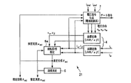
- FIG. 6 is a block diagram showing the configuration of the normal time control unit 23.
- the rotational phase difference estimator 5b estimates the rotational phase angle of the synchronous machine and the phase difference ⁇ of the ⁇ axis rotational coordinate system from the current response values detected by the current detector 3 and input via the coordinate converter 8. To do.
- the ⁇ axis is an estimated axis of the rotor d axis
- the ⁇ axis is an estimated axis orthogonal to the ⁇ axis.
- the PLL Phase Locked Loop
- the PLL Phase Locked Loop
- the PLL performs, for example, PI control using the phase difference ⁇ estimated by the rotational phase difference estimation unit 5b, and calculates the angular velocity ⁇ est of the rotor.
- the integrating unit 25 integrates the angular velocity ⁇ est with the initial estimated phase ⁇ est0 as an initial value, and outputs the estimated phase ⁇ est .
- the coordinate conversion unit 8 performs coordinate conversion between the three-phase fixed coordinate system and the ⁇ axis rotation coordinate system using the estimated phase ⁇ est .
- the current control unit 10 compares the current response values i ⁇ and i ⁇ detected by the current detection unit with the current command values i ⁇ ref and i ⁇ ref to determine voltage command values v ⁇ and v ⁇ .
- the coordinate conversion unit 11 performs coordinate conversion between the ⁇ axis rotation coordinate system and the three-phase fixed coordinate system.
- the triangular wave PWM modulation unit 12 modulates a voltage command value (modulation factor command value) for driving the synchronous machine 2 by the triangular wave PWM, and outputs a gate signal that is an ON / OFF command for each phase switching element of the inverter 1. To do.
- phase angle is estimated in the rotating coordinate system
- the method of estimating the phase angle in the fixed coordinate system shown in the first embodiment may be used.
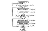
- FIG. 7 is a flowchart showing the operation of this embodiment. This operation is performed under the control of the control unit 24.
- step 01 the main control unit 24 determines whether or not a motor start command is input from a cab or the like (not shown), and proceeds to step 02 if the motor is started.
- step 02 the start-up control unit (current tracking type PWM) 21 performs current control to start the motor 2.
- Current tracking type PWM is a method of directly generating a PWM signal so that the instantaneous value of the inverter output current follows a reference value.
- This current follow-up type PWM is characterized by a very fast current response, and is suitable for suppressing the current at the time of startup, and can prevent the DC side of the inverter 1 from becoming an overvoltage as described above.
- step 03 the rotational phase angle and angular velocity are estimated using the current or voltage command (gate command) generated in step 02.
- the method used for estimation is, for example, the extended induced voltage method described in the first embodiment.
- step 04 it is determined whether or not to switch to the normal control unit (voltage modulation type PWM) 23. This switching may be determined according to time, may be when the phase estimation is settled, may be when the torque rises, or may be when the torque rises and is settled.
- This switching may be determined according to time, may be when the phase estimation is settled, may be when the torque rises, or may be when the torque rises and is settled.
- step 05 the estimated phase ⁇ est and the estimated speed ⁇ est determined by the startup control unit 21 are set in the initial setting unit 22, and the mode switch 20 is switched to the normal time control unit 23 side.
- the normal control unit 23 performs current control by voltage modulation type PWM using these set values.
- the voltage modulation type PWM is a method in which a voltage command (modulation rate command) is calculated by current control and PWM is performed based on the voltage control, such as a combination method such as dq axis current control and triangular wave comparison PWM.
- step 06 the rotational phase angle and angular velocity are estimated using the current or voltage command (gate command) generated in step 05.
- the method used for estimation may be either the same method as step 03 or a different method.
- a method using an induced voltage or a method using an inductance may be used.
- step 07 it is determined whether or not a motor stop command has been input. If the motor stop command is received, the control is terminated.
- the phase is generally not known when the vehicle starts up from a free-run state, the no-load induced voltage cannot be suppressed by feedforward. Therefore, it is only necessary to suppress the no-load induced voltage by causing the flowing current to follow the command current. Therefore, the most effective method is to increase the current control response. This can prevent the current from becoming an overcurrent.
- a current follow-up type PWM is used at the time of startup as in the present embodiment.
- the current tracking type PWM is characterized by high current responsiveness, and can be controlled without using phase information particularly when the current command (i dref , i qref in FIG. 5) is zero. . Therefore, by using the current follow-up type PWM at the time of starting, torque shock (single vibration with large amplitude) and overcurrent at the time of starting can be suppressed.
- the method shown in the first embodiment can be mentioned.
- voltage modulation type PWM is more preferable than current tracking type PWM.
- the method of switching to the voltage modulation type PWM that can suppress the torque shock using the current follow-up type PWM only at the start-up and can realize the stable sensorless control after the start-up as in the second embodiment is the sensorless control. It is suitable as a restart method from a free-run state, and it can be said that stable restart can be realized.
- the current control gain is increased only at the time of start-up or the switching frequency is increased so that the voltage vector can be updated quickly. By doing so, the current control response can be improved.
- the switching frequency is increased more than usual at the time of startup
- either voltage modulation type PWM or current tracking type PWM is possible.
- the current control response can be increased, and the torque shock at startup can be suppressed.
- This embodiment is an embodiment relating to a NS determination method of a rotor of a permanent magnet synchronous motor.
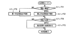
- FIG. 8 is a flowchart showing the operation of the third embodiment.
- step 11 one is selected from a plurality of NS determination methods according to the angular velocity. Although two determination methods are shown in FIG. 8, one of three or more NS determination methods may be selected according to the angular velocity.
- step 12 NS discrimination is performed by the first NS discrimination method. The first NS discrimination method will be described later.
- step 13 NS discrimination is performed by the second NS discrimination method. The second NS discrimination method will also be described later.
- step 14 as a result of the determination in steps 12 and 13, it is determined whether or not phase inversion is necessary.
- step 15 when it is determined in step 14 that inversion is necessary, the estimated phase is advanced 180 degrees to invert the phase (which may of course be delayed 180 degrees). This completes the NS determination routine.
- the first NS discriminating method uses a general magnetic saturation. NS determination is performed by applying positive and negative voltages in the d-axis direction of the estimated coordinate system and utilizing the difference in the amplitude of the flowing current between the N pole and the S pole due to magnetic saturation.
- the second NS discriminating method uses the induced voltage according to the present embodiment. Details including the effects will be described below.
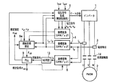
- FIG. 9 shows the configuration of a system that employs the second NS discrimination method.
- the basic configuration is the same as that of the first embodiment, a coordinate conversion unit 8, an NS determination unit 13, and a PLL 9 are added.
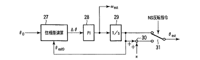
- FIG. 10 is a block diagram showing the configuration of the PLL 9.
- the phase difference calculator 27 calculates a phase difference ⁇ between the estimated phase ⁇ e0 input from the rotational phase estimator 5a and the estimated phase ⁇ est0 that is the output signal of the own circuit.
- the PI control unit 28 performs PI control based on the phase difference ⁇ and provides an estimated angular velocity ⁇ est .
- the estimated angular velocity ⁇ est is integrated by the integrating unit 29, and the estimated phase ⁇ est0 is output.
- the adder 30 adds ⁇ to the estimated phase ⁇ est0 .
- the switch 31 selects one of the estimated phases ⁇ est0 obtained by adding the estimated phases ⁇ est0 and ⁇ based on the NS inversion command, and outputs the estimated phase ⁇ est .
- the main control unit 26 is connected to each of the blocks described above and comprehensively controls the motor control device.
- NS discrimination according to the present embodiment will be described.
- NS is discriminated from the ⁇ -axis current in the estimated coordinate system corresponding to the q-axis current in the dq coordinate system.
- Equation (5) When estimating the phase using Equation (5), the sign of E 0x may change depending on the sign of the current differential term as shown in Equation (4), and the estimated phase ⁇ is calculated with an opposite value of 180 degrees. Sometimes. Therefore, as shown in FIG. 10, when the PLL is used, the phase held by the PLL may also be a value opposite to 180 degrees, and NS determination is necessary regardless of the angular velocity.
- NS discrimination is used in the low speed range, and since the induced voltage is small, a method using magnetic saturation is widely used. However, in the method using magnetic saturation, NS saturation is caused to cause magnetic saturation. Time is needed.
- the high voltage region region where the no-load induced voltage is higher than the DC side voltage of the inverter
- the induced voltage can be used in a region where the voltage is large (the angular velocity is high) as in the above-described high voltage region, NS determination can be performed in a short time by using the induced voltage.
- the induced voltage is very small at low speed, sufficient accuracy cannot be expected. Therefore, it is preferable to have two NS discrimination methods suitable for the low speed range and NS discrimination method suitable for the high speed range, and enable NS discrimination in a short time in the high speed range. This is the main content of the third embodiment.
- the voltage is selected in a direction that cancels the no-load induced voltage. Therefore, for example, the direction in which the most voltage vectors are selected is the direction in which the no-load induced voltage is canceled, and the direction of the no-load induced voltage can be estimated from there (see FIG. 11). The direction in this case cannot be estimated with high accuracy, but sufficient accuracy can be obtained for NS discrimination. Alternatively, NS determination can also be made by determining which one of the voltage vector closest to the ⁇ axis corresponding to the q axis and the voltage vector opposite by 180 degrees is selected in the control (see FIG. 12). .
- the average vector of the current is the ⁇ q axis direction, which is the direction of the current flowing by the no-load induced voltage. Therefore, for example, as shown in FIG. 13, the integral of the ⁇ -axis current corresponding to the q-axis is taken in the control, and if it becomes equal to or greater than a certain threshold value, it can be determined that NS discrimination is necessary. Alternatively, the determination can be made using the average value of the ⁇ -axis current.
- the NS determination flowchart is not limited to FIG. 8 and may be, for example, FIG.
- step 21 NS discrimination is performed by the second NS discrimination method. This is the same as step 13.
- step 22 it is determined whether NS discrimination has been confirmed in step 21. It is determined whether NS determination has been confirmed by either “confirmed that reversal is necessary” or “confirmed that reversal is not performed because the position is correct”.
- step 23 it is determined whether a certain time has elapsed. If the second NS discriminating method cannot be discriminated after a predetermined time has passed, the process proceeds to step 24.
- step 24 NS determination is performed by the first NS determination method. This is the same as step 12.
- step 25 as a result of the determination in steps 21 and 24, it is determined whether or not phase inversion is necessary. This is the same as step 14.
- step 26 when it is determined in step 25 that inversion is necessary, the estimated phase is advanced 180 degrees to invert the phase. (Of course, it may be delayed by 180 degrees) This is the same as step 15. This completes the NS determination routine.
- FIG. 15 is a block diagram showing the configuration of the fourth embodiment.
- the load contactor is between the current detector and PMSM, but the load contactor may be between the current detector and the inverter 1.
- the no-load induced voltage is higher than the DC side voltage of the inverter 1.
- the winding current flows at the moment when the load contactor is closed.
- the direct current of the inverter 1 flows.
- the voltage on the DC side of the inverter 1 varies. Therefore, it can be determined as a high voltage region by detecting any of these.
- L d represents the inductance in the direction of the magnetic flux of the magnet
- ⁇ max represents the maximum angular velocity
- V dc represents the voltage on the DC side of the inverter 1 obtained by the above-described DC voltage detecting means
- ⁇ f represents the permanent magnet.
- the present invention is applied to a synchronous motor or the like that is mounted on a train or the like and drives the train or the like.
Landscapes
- Engineering & Computer Science (AREA)
- Power Engineering (AREA)
- Control Of Ac Motors In General (AREA)
- Control Of Motors That Do Not Use Commutators (AREA)
- Motor And Converter Starters (AREA)
Abstract
Un mode de réalisation de ce dispositif de commande sans capteur de rotation consiste en un dispositif de commande commandant un onduleur (1) entraînant un dispositif synchrone (2), et équipé d'unités (5, 6) d'estimation de l'angle de phase et de la vitesse angulaire estimant l'angle de phase et la vitesse angulaire d'un rotor au moyen de l'inductance et de la tension induite du dispositif synchrone précédemment mentionné, et d'unités de commande (24, 26) commandant le courant électrique délivré par ledit onduleur (1) tout en produisant une valeur de commande de tension au moyen d'une MID ne sélectionnant qu'un vecteur de tension différent de zéro lorsque ledit onduleur (1) et le moteur électrique (2) passent du fonctionnement libre au démarrage. Lesdites unités (5,6) d'estimation d'angle de phase et de vitesse angulaire utilisent la valeur de commande de tension susmentionnée et le courant électrique produit par l'onduleur pour estimer l'angle de phase de rotation et la vitesse angulaire susmentionnés.
Priority Applications (3)
| Application Number | Priority Date | Filing Date | Title |
|---|---|---|---|
| EP11783271.7A EP2573934B1 (fr) | 2010-05-20 | 2011-05-17 | Dispositif de commande sans capteur de rotation |
| CN201180025051.4A CN102986133B (zh) | 2010-05-20 | 2011-05-17 | 旋转无传感器控制装置 |
| US13/198,607 US8519649B2 (en) | 2010-05-20 | 2011-08-04 | Control device of a synchronous motor |
Applications Claiming Priority (2)
| Application Number | Priority Date | Filing Date | Title |
|---|---|---|---|
| JP2010-116601 | 2010-05-20 | ||
| JP2010116601A JP5534935B2 (ja) | 2010-05-20 | 2010-05-20 | 回転センサレス制御装置 |
Publications (1)
| Publication Number | Publication Date |
|---|---|
| WO2011145334A1 true WO2011145334A1 (fr) | 2011-11-24 |
Family
ID=44991452
Family Applications (1)
| Application Number | Title | Priority Date | Filing Date |
|---|---|---|---|
| PCT/JP2011/002738 WO2011145334A1 (fr) | 2010-05-20 | 2011-05-17 | Dispositif de commande sans capteur de rotation |
Country Status (5)
| Country | Link |
|---|---|
| US (1) | US8519649B2 (fr) |
| EP (1) | EP2573934B1 (fr) |
| JP (1) | JP5534935B2 (fr) |
| CN (1) | CN102986133B (fr) |
| WO (1) | WO2011145334A1 (fr) |
Cited By (3)
| Publication number | Priority date | Publication date | Assignee | Title |
|---|---|---|---|---|
| US9705438B2 (en) | 2015-07-14 | 2017-07-11 | Infineon Technologies Austria Ag | Controller for a free-running motor |
| CN107733298A (zh) * | 2016-08-10 | 2018-02-23 | 大众汽车有限公司 | 确定旋转电机旋转方向的方法和设备、汽车和程序产品 |
| CN110224641A (zh) * | 2018-03-01 | 2019-09-10 | 株式会社东芝 | 电机控制用集成电路 |
Families Citing this family (23)
| Publication number | Priority date | Publication date | Assignee | Title |
|---|---|---|---|---|
| JP2013183532A (ja) * | 2012-03-01 | 2013-09-12 | Toshiba Corp | モータ制御装置及びその制御方法 |
| CN102647134B (zh) * | 2012-04-01 | 2014-08-13 | 南京航空航天大学 | 一种永磁同步电机无角度传感器的效率优化控制方法 |
| ITVI20120331A1 (it) * | 2012-12-10 | 2014-06-11 | Reel Srl | Metodo per la sincronizzazione di una macchina elettrica sincrona a riluttanza |
| JP6317904B2 (ja) * | 2013-10-02 | 2018-04-25 | 日立ジョンソンコントロールズ空調株式会社 | モータ制御装置、及び空気調和機 |
| EP2860870B1 (fr) * | 2013-10-14 | 2018-06-20 | Bombardier Transportation GmbH | Procédé de démarrage d'un moteur à aimants permanents sans capteur |
| JP6021784B2 (ja) * | 2013-10-23 | 2016-11-09 | 三菱電機株式会社 | 同期回転機の磁極位置検出方法 |
| TWI551007B (zh) * | 2015-03-13 | 2016-09-21 | 光寶電子(廣州)有限公司 | 伺服馬達系統及其控制方法 |
| CN104980076A (zh) * | 2015-06-29 | 2015-10-14 | 苏州八方电机科技有限公司 | 一种永磁电机系统的弱磁故障控制方法 |
| JP6580899B2 (ja) * | 2015-08-26 | 2019-09-25 | 株式会社東芝 | ドライブシステムおよびインバータ装置 |
| TWI668953B (zh) | 2016-08-22 | 2019-08-11 | 日商東芝股份有限公司 | Inverter control device and drive system |
| JP6767213B2 (ja) | 2016-09-05 | 2020-10-14 | 東芝インフラシステムズ株式会社 | インバータ制御装置および電動機駆動システム |
| TWI654827B (zh) * | 2016-09-05 | 2019-03-21 | 日商東芝股份有限公司 | 換流器控制裝置及馬達驅動系統 |
| US9948224B1 (en) * | 2016-10-17 | 2018-04-17 | General Electric Company | System and method for sensorless control of electric machines using magnetic alignment signatures |
| WO2018135007A1 (fr) * | 2017-01-23 | 2018-07-26 | 東芝三菱電機産業システム株式会社 | Dispositif de commande de moteur électrique synchrone |
| US11486404B1 (en) * | 2017-10-30 | 2022-11-01 | Hkc-Us, Llc | Switch housing remote control |
| US11374513B2 (en) * | 2019-01-23 | 2022-06-28 | Allegro Microsystems, Llc | Motor control circuit with degauss filter |
| US11575336B2 (en) | 2019-05-31 | 2023-02-07 | Nxp Usa, Inc. | Technique for on-the-fly start-up of a permanent magnet AC motor without a speed or position sensor |
| CN110623598B (zh) * | 2019-10-18 | 2021-07-20 | 峰岹科技(深圳)股份有限公司 | 吸尘器控制方法和装置、吸尘器 |
| CN112311216B (zh) * | 2020-10-15 | 2021-09-21 | 湖南大学 | 一种变流器过流抑制方法及装置 |
| WO2022153436A1 (fr) * | 2021-01-14 | 2022-07-21 | 三菱電機株式会社 | Dispositif de conversion de puissance et système de climatisation |
| JP7038931B1 (ja) * | 2021-05-20 | 2022-03-18 | 三菱電機株式会社 | 回転機制御装置、機械学習装置および推論装置 |
| US11777424B2 (en) * | 2021-10-06 | 2023-10-03 | Elite Semiconductor Microelectronics Technology Inc. | Method for determining initial rotor position of permanent magnet synchronous motor according to phase current differences and line current differences and associated motor device |
| FR3135845A1 (fr) * | 2022-05-18 | 2023-11-24 | Safran Electrical & Power | Dispositif de contrôle pour une machine tournante triphasée synchrone à aimants permanents |
Citations (8)
| Publication number | Priority date | Publication date | Assignee | Title |
|---|---|---|---|---|
| JPH07177788A (ja) | 1993-10-26 | 1995-07-14 | Toyota Motor Corp | 電気角検出装置およびこれを用いた同期モータの駆動装置 |
| JP3267528B2 (ja) | 1997-05-16 | 2002-03-18 | 川崎製鉄株式会社 | ステンレス鋼帯用研摩設備 |
| JP3486326B2 (ja) | 1997-06-23 | 2004-01-13 | トヨタ自動車株式会社 | 同期モータの運転制御方法およびその装置 |
| JP2004328920A (ja) * | 2003-04-25 | 2004-11-18 | Yaskawa Electric Corp | 交流電動機のセンサレス制御方法及び制御装置 |
| JP2005065410A (ja) * | 2003-08-12 | 2005-03-10 | Toshiba Corp | モータ制御装置 |
| JP3636340B2 (ja) | 1997-06-30 | 2005-04-06 | 富士電機機器制御株式会社 | 交流回転機用電力変換装置 |
| JP2008001690A (ja) | 2006-05-26 | 2008-01-10 | Pharma Frontier Kk | Gタンパク質共役型レセプターの作動剤および医薬 |
| JP2008199864A (ja) * | 2007-02-16 | 2008-08-28 | Fuji Electric Fa Components & Systems Co Ltd | 永久磁石形同期電動機の制御装置 |
Family Cites Families (12)
| Publication number | Priority date | Publication date | Assignee | Title |
|---|---|---|---|---|
| US6401875B1 (en) * | 2001-02-12 | 2002-06-11 | Otis Elevator Company | Absolute position sensing method and apparatus for synchronous elevator machines by detection stator iron saturation |
| WO2004006424A1 (fr) * | 2002-07-08 | 2004-01-15 | Kabushiki Kaisha Yaskawa Denki | Procede de commande vecteur, sans detecteur, d'un generateur a courant alternatif |
| JP2004180368A (ja) * | 2002-11-25 | 2004-06-24 | Yaskawa Electric Corp | 誘導電動機磁束推定器の推定値補正方法 |
| JP4589093B2 (ja) * | 2004-12-10 | 2010-12-01 | 日立オートモティブシステムズ株式会社 | 同期モータ駆動装置及び方法 |
| JP4480696B2 (ja) * | 2005-08-26 | 2010-06-16 | 三洋電機株式会社 | モータ制御装置 |
| JP4754379B2 (ja) * | 2006-03-22 | 2011-08-24 | 本田技研工業株式会社 | 電動機の制御装置 |
| JP4198162B2 (ja) * | 2006-04-07 | 2008-12-17 | 三洋電機株式会社 | モータ制御装置 |
| KR101037519B1 (ko) * | 2006-06-29 | 2011-05-26 | 미쓰비시덴키 가부시키가이샤 | 교류 회전기의 제어 장치 |
| FR2903538B1 (fr) | 2006-07-07 | 2008-09-26 | Schneider Toshiba Inverter Eur Sas | Procede et dispositif d'estimation de la vitesse d'un moteur electrique |
| JP4901517B2 (ja) * | 2007-02-08 | 2012-03-21 | 株式会社東芝 | 交流電動機制御装置 |
| JP4988374B2 (ja) * | 2007-02-15 | 2012-08-01 | 三洋電機株式会社 | モータ制御装置 |
| JP2009201284A (ja) * | 2008-02-22 | 2009-09-03 | Meidensha Corp | Pmモータの可変速駆動装置 |
-
2010
- 2010-05-20 JP JP2010116601A patent/JP5534935B2/ja active Active
-
2011
- 2011-05-17 WO PCT/JP2011/002738 patent/WO2011145334A1/fr active Application Filing
- 2011-05-17 CN CN201180025051.4A patent/CN102986133B/zh active Active
- 2011-05-17 EP EP11783271.7A patent/EP2573934B1/fr active Active
- 2011-08-04 US US13/198,607 patent/US8519649B2/en active Active
Patent Citations (8)
| Publication number | Priority date | Publication date | Assignee | Title |
|---|---|---|---|---|
| JPH07177788A (ja) | 1993-10-26 | 1995-07-14 | Toyota Motor Corp | 電気角検出装置およびこれを用いた同期モータの駆動装置 |
| JP3267528B2 (ja) | 1997-05-16 | 2002-03-18 | 川崎製鉄株式会社 | ステンレス鋼帯用研摩設備 |
| JP3486326B2 (ja) | 1997-06-23 | 2004-01-13 | トヨタ自動車株式会社 | 同期モータの運転制御方法およびその装置 |
| JP3636340B2 (ja) | 1997-06-30 | 2005-04-06 | 富士電機機器制御株式会社 | 交流回転機用電力変換装置 |
| JP2004328920A (ja) * | 2003-04-25 | 2004-11-18 | Yaskawa Electric Corp | 交流電動機のセンサレス制御方法及び制御装置 |
| JP2005065410A (ja) * | 2003-08-12 | 2005-03-10 | Toshiba Corp | モータ制御装置 |
| JP2008001690A (ja) | 2006-05-26 | 2008-01-10 | Pharma Frontier Kk | Gタンパク質共役型レセプターの作動剤および医薬 |
| JP2008199864A (ja) * | 2007-02-16 | 2008-08-28 | Fuji Electric Fa Components & Systems Co Ltd | 永久磁石形同期電動機の制御装置 |
Cited By (4)
| Publication number | Priority date | Publication date | Assignee | Title |
|---|---|---|---|---|
| US9705438B2 (en) | 2015-07-14 | 2017-07-11 | Infineon Technologies Austria Ag | Controller for a free-running motor |
| CN107733298A (zh) * | 2016-08-10 | 2018-02-23 | 大众汽车有限公司 | 确定旋转电机旋转方向的方法和设备、汽车和程序产品 |
| CN110224641A (zh) * | 2018-03-01 | 2019-09-10 | 株式会社东芝 | 电机控制用集成电路 |
| CN110224641B (zh) * | 2018-03-01 | 2023-04-28 | 株式会社东芝 | 电机控制用集成电路 |
Also Published As
| Publication number | Publication date |
|---|---|
| CN102986133B (zh) | 2015-09-16 |
| EP2573934A1 (fr) | 2013-03-27 |
| JP2011244655A (ja) | 2011-12-01 |
| US20110285337A1 (en) | 2011-11-24 |
| EP2573934B1 (fr) | 2019-10-30 |
| US8519649B2 (en) | 2013-08-27 |
| EP2573934A4 (fr) | 2017-08-30 |
| JP5534935B2 (ja) | 2014-07-02 |
| CN102986133A (zh) | 2013-03-20 |
Similar Documents
| Publication | Publication Date | Title |
|---|---|---|
| JP5534935B2 (ja) | 回転センサレス制御装置 | |
| KR100761928B1 (ko) | 영구 자석 센서리스 제어를 위한 셀프 튜닝 방법 및 장치 | |
| KR100423715B1 (ko) | 동기전동기 제어장치, 동기전동기의 제어방법 | |
| JP6367332B2 (ja) | インバータ制御装置及びモータ駆動システム | |
| JP4989075B2 (ja) | 電動機駆動制御装置及び電動機駆動システム | |
| TWI587622B (zh) | Drive system and inverter device | |
| JP2019533409A (ja) | 同期モータを始動させるためのシステム及び方法 | |
| KR102285399B1 (ko) | 인버터 제어 장치 및 드라이브 시스템 | |
| JP2010063208A (ja) | 同期電動機の駆動システム、及びこれに用いる制御装置 | |
| JP5428202B2 (ja) | 永久磁石形同期電動機の制御装置 | |
| JP3894286B2 (ja) | 永久磁石同期電動機の制御装置 | |
| JP6726390B2 (ja) | 永久磁石形同期電動機の制御装置 | |
| JP5277724B2 (ja) | 永久磁石形同期電動機の制御装置 | |
| JP5509167B2 (ja) | 同期電動機の制御システム | |
| JP5250603B2 (ja) | モータ制御装置 | |
| US20150188461A1 (en) | Motor driving control apparatus and method, and motor driving system using the same | |
| KR20090055070A (ko) | 영구자석 동기 모터 제어시스템 및 제어방법 | |
| JP6908888B2 (ja) | 同期電動機の制御装置 | |
| JP5332305B2 (ja) | 永久磁石形同期電動機の制御装置 | |
| WO2021117303A1 (fr) | Dispositif de diagnostic de démagnétisation pour moteur et procédé de diagnostic de démagnétisation pour dispositif de commande de moteur | |
| JP2008017577A (ja) | 同期モータ制御装置 | |
| JP6573213B2 (ja) | 永久磁石形同期電動機の制御装置 | |
| JP2019068515A (ja) | モータ制御装置 | |
| JP6787006B2 (ja) | モータ制御装置 | |
| JP2018007492A (ja) | 制御装置、制御方法および制御プログラム |
Legal Events
| Date | Code | Title | Description |
|---|---|---|---|
| WWE | Wipo information: entry into national phase |
Ref document number: 201180025051.4 Country of ref document: CN |
|
| 121 | Ep: the epo has been informed by wipo that ep was designated in this application |
Ref document number: 11783271 Country of ref document: EP Kind code of ref document: A1 |
|
| WWE | Wipo information: entry into national phase |
Ref document number: 2011783271 Country of ref document: EP |
|
| NENP | Non-entry into the national phase |
Ref country code: DE |