WO2011125898A1 - 磁気ディスク用ガラス基板の製造方法 - Google Patents
磁気ディスク用ガラス基板の製造方法 Download PDFInfo
- Publication number
- WO2011125898A1 WO2011125898A1 PCT/JP2011/058328 JP2011058328W WO2011125898A1 WO 2011125898 A1 WO2011125898 A1 WO 2011125898A1 JP 2011058328 W JP2011058328 W JP 2011058328W WO 2011125898 A1 WO2011125898 A1 WO 2011125898A1
- Authority
- WO
- WIPO (PCT)
- Prior art keywords
- glass substrate
- magnetic disk
- cleaning
- peroxodisulfate
- polishing
- Prior art date
- Legal status (The legal status is an assumption and is not a legal conclusion. Google has not performed a legal analysis and makes no representation as to the accuracy of the status listed.)
- Ceased
Links
Classifications
-
- G—PHYSICS
- G11—INFORMATION STORAGE
- G11B—INFORMATION STORAGE BASED ON RELATIVE MOVEMENT BETWEEN RECORD CARRIER AND TRANSDUCER
- G11B5/00—Recording by magnetisation or demagnetisation of a record carrier; Reproducing by magnetic means; Record carriers therefor
- G11B5/84—Processes or apparatus specially adapted for manufacturing record carriers
- G11B5/8404—Processes or apparatus specially adapted for manufacturing record carriers manufacturing base layers
-
- C—CHEMISTRY; METALLURGY
- C03—GLASS; MINERAL OR SLAG WOOL
- C03C—CHEMICAL COMPOSITION OF GLASSES, GLAZES OR VITREOUS ENAMELS; SURFACE TREATMENT OF GLASS; SURFACE TREATMENT OF FIBRES OR FILAMENTS MADE FROM GLASS, MINERALS OR SLAGS; JOINING GLASS TO GLASS OR OTHER MATERIALS
- C03C23/00—Other surface treatment of glass not in the form of fibres or filaments
- C03C23/0075—Cleaning of glass
Definitions
- the present invention relates to a method for producing a glass substrate for a magnetic disk.
- a magnetic disk used for an HDD which is one of magnetic recording media, has been rapidly reduced in size, thinned, and increased in recording density and access speed.
- a magnetic disk having a magnetic layer on a disk-shaped substrate is rotated at high speed, and recording and reproduction are performed while a magnetic head is flying over the magnetic disk.
- the magnetic head Since the rotation speed of the magnetic disk increases as the access speed increases, a higher substrate strength is required for the magnetic disk. As the recording density increases, the magnetic head is also changing from a thin film head to a magnetoresistive head (MR head) and a large magnetoresistive head (GMR head), and the flying height of the magnetic head from the magnetic disk is increased. It has narrowed to about 8 nm. For this reason, if there are irregularities on the surface of the magnetic disk, there may be a crash failure in which the magnetic head collides, or a thermal asperity failure that causes a read error due to adiabatic compression or contact of air. In order to suppress such troubles in the magnetic head, it is important to finish the main surface of the magnetic disk as a very smooth surface.
- a glass substrate is used instead of a conventional aluminum substrate as a substrate for a magnetic disk.
- a glass substrate made of glass that is a hard material is superior in flatness, substrate strength, and rigidity of the substrate surface compared to an aluminum substrate made of a metal that is a soft material.
- Glass substrates used for these magnetic disks are manufactured by subjecting the main surface to grinding or polishing. As a grinding process or a polishing process for a glass substrate, there is a method in which a double-side polishing apparatus having a planetary gear mechanism is used.
- a glass substrate is sandwiched between upper and lower surface plates to which a polishing pad (polishing cloth) is attached, and a polishing liquid in which abrasive grains (slurry) are turbid is supplied between the polishing pad and the glass substrate,
- the main surface of the glass substrate is finished to a predetermined smooth surface by moving the glass substrate relative to the upper and lower surface plates (see, for example, Patent Document 1).
- a recording / reproducing track is formed by forming a thin film (magnetic layer) of several nanometers on a glass substrate for a magnetic disk whose surface is smoothed by grinding or polishing. Therefore, in the manufacturing process of a glass substrate for magnetic disks, it is important to keep the substrate surface clean by removing slight contamination of the glass substrate surface at the same time as smoothing by grinding or polishing. Yes.
- the glass substrate has an aspect that it is a brittle material. Therefore, in the manufacturing process of the magnetic disk glass substrate, the glass substrate is immersed in a heated chemical strengthening solution, and lithium ions and sodium ions on the surface of the glass substrate are ion-exchanged with sodium ions and potassium ions in the chemical strengthening solution, respectively. Thus, a compressive stress layer is formed on the surface layer of the glass substrate and strengthened (chemical strengthening step).
- a stainless steel member may be used for a grinding device and a polishing device as shown in Patent Document 1.
- a stainless steel material may be used in the chemical strengthening process. That is, when a process using a stainless steel device is performed, there is a possibility that metal-based contaminants resulting from stainless steel are generated from these devices and adhere to the glass substrate.
- Contamination with metallic fine particles causes irregularities on the surface of the magnetic layer after film formation, which reduces the electrical characteristics and yield of products such as recording and playback. Therefore, it must be removed in the manufacturing process of the magnetic recording disk glass substrate. In particular, in consideration of the fact that the flying height of the magnetic head from the magnetic disk becomes smaller as the recording density increases, it is also necessary to consider the contaminants caused by the material of the apparatus.
- DFH Dynamic Flying Height
- the main surface of the magnetic disk is smoother and more than conventional. It has been found that it is necessary to clean with few defects such as foreign matter.
- the DFH head instead of lowering the flying height of the head main body and approaching the magnetic disk surface, only the periphery of the head element portion is projected and brought closer to the medium surface. Is considered to be affected.
- the distance between the protruding head element portion and the magnetic disk is preferably 1 nm or less.
- the present invention has been made in view of the above problems, and in a glass substrate for a magnetic disk, effectively removes metal-based contaminants adhering to the glass substrate surface without increasing the roughness of the glass substrate surface. Is one of the purposes.
- the method for producing a glass substrate for a magnetic disk according to the present invention is a method for producing a glass substrate for a magnetic disk having a glass substrate washing step, and the washing step comprises subjecting glass to a washing solution containing peroxodisulfate and having a pH of 2 or more and 4 or less. It has the process which makes a board
- the concentration of peroxodisulfate in the cleaning liquid is 0.005 mol / L or more and 1 mol / L or less.
- the peroxodisulfate is preferably ammonium peroxodisulfate.
- the pH of the cleaning liquid is preferably 3 or more and 4 or less.
- glass is formed without increasing the roughness of the surface of the glass substrate by performing a cleaning process having a process of bringing the glass substrate into contact with a cleaning liquid containing peroxodisulfate and having a pH of 2 or more and 4 or less. Metal contaminants adhering to the substrate surface can be effectively removed.
- One of the methods for manufacturing a magnetic disk glass substrate shown in the present embodiment includes a cleaning process for removing metallic contaminants on the glass substrate, and the cleaning process oxidizes the metallic contaminants on the glass substrate.
- a cleaning solution containing peroxodisulfate ions is used.
- cleaning can be performed under acidic conditions using a cleaning liquid containing peroxodisulfate ions.
- peroxodisulfate ions exhibit a very strong oxidizing power under acidic conditions, it is possible to oxidize and ionize metal contaminants that are not easily corroded, such as stainless steel, and dissolve them in the liquid. Thereby, the metallic contaminant adhering to the glass substrate surface can be effectively removed.
- the method for manufacturing a glass substrate for a magnetic disk shown in the present embodiment is characterized by performing a cleaning step having a process of bringing a glass substrate into contact with a cleaning liquid containing peroxodisulfate and having a pH of 2 or more and 4 or less.
- the cleaning liquid can be prepared by adding peroxodisulfate to an acidic solution.
- ammonium peroxodisulfate As peroxodisulfate, ammonium peroxodisulfate, sodium peroxodisulfate, potassium peroxodisulfate and the like can be used. Ammonium peroxodisulfate is a strong oxidizing substance and is easily dissolved in water (solubility 36.8%; 20 ° C.) and dissociates as follows.
- Peroxodisulfate exhibits a strong oxidizing power in an acidic solution and dissolves metal-based contaminants (iron oxide) firmly adhered to the glass substrate.
- metal-based contaminants iron oxide
- peroxodisulfuric acid hydrolyzes in water to produce acidic ammonium sulfite and hydrogen peroxide, and exhibits extremely strong oxidizing power. Utilizing this oxidizing power, the metallic contaminants firmly adhered on the substrate can be oxidized and dissolved in water.
- the acidic solution to which peroxodisulfate is added sulfuric acid, nitric acid and the like can be applied.
- the pH of the cleaning solution is adjusted to 2 or more and 4 or less, preferably 3 or more and 4 or less. When the pH is less than 2, the roughness of the glass substrate surface is increased, and when the pH exceeds 4, the metal contaminants on the glass substrate surface cannot be sufficiently removed.
- the concentration of peroxodisulfate in the cleaning liquid is preferably 0.005 mol / L or more and 1 mol / L or less. If the concentration is less than 0.005 mol / L, metal contaminants on the surface of the glass substrate cannot be sufficiently removed, and even if the concentration exceeds 1 mol / L, no further effect can be obtained.
- plate glass can be used in the material processing step.
- This plate-like glass can be manufactured by using a known manufacturing method such as a press method, a float method, a downdraw method, a redraw method, or a fusion method using a molten glass as a material.
- a press method if a press method is used, a sheet glass can be produced at a low cost.
- both main surfaces of the disk-shaped glass are lapped to adjust mainly the flatness and thickness of the glass substrate.
- This lapping process can be performed using alumina free abrasive grains with a double-sided lapping apparatus using a planetary gear mechanism. Specifically, the lapping platen is pressed on both sides of the disk-shaped glass from above and below, a grinding liquid containing free abrasive grains is supplied onto the main surface of the disk-shaped glass, and these are moved relative to each other for lapping. Do. By this lapping process, a glass substrate having a flat main surface can be obtained.
- Shape processing step (coring step for forming a hole, chamfering step for forming a chamfered surface at the end (outer peripheral end and inner peripheral end) (chamfered surface forming step)
- an inner hole is formed at the center of the glass substrate using a cylindrical diamond drill to obtain an annular glass substrate.
- the inner peripheral end surface and the outer peripheral end surface are ground with a diamond grindstone, and a predetermined chamfering process is performed.
- Second Lapping Step the second lapping process is performed on both main surfaces of the obtained glass substrate in the same manner as in the first lapping step.
- this second lapping step for example, the fine uneven shape formed on the main surface in the previous shape processing step can be removed in advance, and the subsequent polishing step for the main surface can be performed in a short time. Can be completed.
- the end surface polishing step the outer peripheral end surface and the inner peripheral end surface of the glass substrate are mirror-polished by a brush polishing method.
- abrasive grains for example, a slurry containing cerium oxide abrasive grains (free abrasive grains) can be used.
- the end face of the glass substrate can be prevented from the precipitation of sodium and potassium, and in a mirror state that can suppress the generation of particles that cause thermal asperity and the like and the adhesion to the end face portion. Become.
- Main surface polishing step As the main surface polishing step, first, a first polishing step is performed.
- the first polishing process is a process whose main purpose is to remove scratches and distortions remaining on both main surfaces in the lapping process described above.
- both main surfaces are polished using a hard resin polisher by a double-side polishing apparatus having a planetary gear mechanism.
- abrasive cerium oxide abrasive grains can be used.
- the glass substrate after the first polishing step is washed with a neutral detergent, pure water, IPA, or the like.
- Chemical strengthening step the glass substrate that has been subjected to the lapping step and the polishing step described above is chemically strengthened.
- a chemical strengthening solution used for chemical strengthening for example, a mixed solution of potassium nitrate (60%) and sodium nitrate (40%) can be used.
- the chemical strengthening solution is heated to 300 ° C. to 400 ° C., the cleaned glass substrate is preheated to 200 ° C. to 300 ° C., and immersed in the chemical strengthening solution for 3 hours to 4 hours.
- the lithium ions and sodium ions in the surface layer of the glass substrate are respectively replaced with sodium ions and potassium ions having a relatively large ion radius in the chemical strengthening solution.
- the chemically strengthened glass substrate is washed with sulfuric acid and then with pure water, IPA or the like.
- a second polishing process is performed as a final polishing process.
- the second polishing step is a step aimed at finishing both main surfaces into a mirror shape.
- both main surfaces are mirror-polished using a soft foam resin polisher by a double-side polishing apparatus having a planetary gear mechanism.
- cerium oxide abrasive grains or colloidal silica finer than the cerium oxide abrasive grains used in the first polishing step can be used.
- the glass substrate is subjected to a cleaning process after the final polishing process.
- the cleaning process is a process aimed at removing particles adhering to the surface of the glass substrate by the chemical strengthening process and the final polishing process.
- a cleaning process is performed in which the glass substrate is brought into contact with a cleaning solution containing at least peroxodisulfate and having a pH of 2 to 4. Specifically, the glass substrate is immersed in a cleaning solution in which ammonium peroxodisulfate (0.005 mol / L to 1 mol / L) is added to sulfuric acid.
- the pH of the cleaning liquid is preferably adjusted to 2 or more and 4 or less.
- the metal-based contaminant can be effectively removed by performing the above-described cleaning treatment.
- the apparatus used for the chemical strengthening process includes a stainless steel material, the above cleaning process is effective.
- washing cleaning process
- alkali cleaning there is an effect that metal contaminants that cannot be completely dissolved by either acid or alkali can be removed more reliably.
- the configuration in which the cleaning process using the cleaning liquid containing peroxodisulfate is performed after the chemical strengthening process may be performed before or after the chemical strengthening process.
- a cleaning process using a cleaning liquid containing peroxodisulfate can be performed.
- a perpendicular magnetic layer is formed by sequentially forming, for example, an adhesion layer, a soft magnetic layer, a nonmagnetic underlayer, a perpendicular magnetic recording layer, a protective layer, and a lubricating layer on the main surface of the glass substrate obtained through the above-described steps.
- a recording disk can be manufactured.
- the material constituting the adhesion layer include a Cr alloy.
- the material constituting the soft magnetic layer include a CoTaZr-based alloy.
- the nonmagnetic underlayer include a granular nonmagnetic layer.
- An example of the perpendicular magnetic recording layer is a granular magnetic layer.
- Examples of the material constituting the protective layer include hydrogenated carbon.
- Examples of the material constituting the lubrication layer include a fluororesin.
- these recording layers and the like are more specifically formed on a glass substrate by using an in-line type sputtering apparatus, under a CrTi adhesion layer, a CoTaZr / Ru / CoTaZr soft magnetic layer, and a nonmagnetic granular layer of CoCrSiO2.
- a base layer, a CoCrPt—SiO 2 ⁇ TiO 2 granular magnetic layer, and a hydrogenated carbon protective film can be sequentially formed, and a perfluoropolyether lubricating layer can be formed by a dipping method.
- a Ru underlayer may be used in place of the CoCrSiO 2 nonmagnetic granular underlayer.
- a NiW seed layer may be added between the soft magnetic layer and the underlayer.
- a CoCrPtB magnetic layer may be added between the granular magnetic layer and the protective layer.
- Examples and comparative examples (1) Material processing step The melted aluminosilicate glass was molded into a disk shape by direct pressing using an upper mold, a lower mold, and a trunk mold to obtain an amorphous plate glass.
- the main components of the aluminosilicate glass are SiO2: 58 wt% to 75 wt%, Al2O3: 5 wt% to 23 wt%, Li2O: 3 wt% to 10 wt%, and Na2O: 4 wt% to 13 wt%.
- Main surface polishing step As a main surface polishing step, first, a first polishing step was performed. This first polishing step is mainly intended to remove scratches and distortions remaining on the main surface in the lapping step described above. In the first polishing step, the main surface was polished using a hard resin polisher by a double-side polishing apparatus having a planetary gear mechanism. As the abrasive, cerium oxide abrasive grains were used.
- the glass substrate after the first polishing step was sequentially immersed in each washing tank of neutral detergent, pure water, and IPA (isopropyl alcohol) and washed.
- Chemical strengthening process Next, the glass substrate which finished the main surface polishing process was subjected to a chemical strengthening process (ion exchange process).
- a chemical strengthening solution prepared by mixing potassium nitrate (60%) and sodium nitrate (40%) is prepared, and the chemically strengthened solution is heated to 400 ° C., and the cleaned glass substrate is preheated to 300 ° C. And was immersed in the chemical strengthening solution for about 3 hours. In this immersion, in order to chemically strengthen the entire surface of the glass substrate, it was carried out in a state of being housed in a substrate holder so that a plurality of glass substrates were held at the end surfaces.
- the lithium ions and sodium ions in the surface layer of the glass substrate were replaced with sodium ions and potassium ions in the chemical strengthening solution, respectively, and the glass substrate was strengthened.
- a second polishing step was performed as the main surface polishing step.
- the purpose of this second polishing step is to polish the compressive stress layer formed on the glass substrate by a predetermined thickness so that both main surfaces of the glass substrate are finished in a mirror shape.
- the main surface was mirror-polished using a soft foam resin polisher with a double-side polishing apparatus having a planetary gear mechanism.
- the abrasive colloidal silica abrasive grains (average particle diameter of 5 nm to 80 nm) finer than the cerium oxide abrasive grains used in the first polishing step were used.
- the defect was test
- the measurement conditions were a laser wavelength of 405 nm with a laser power of 25 mW and a laser spot diameter of 5 ⁇ m, and a region between 15 mm and 31.5 mm from the center of the glass substrate was measured.
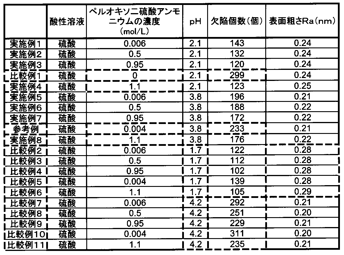
- Table 1 shows the number of fixed defects (per 24 cm 2) among defects detected as a size of 1.0 ⁇ m or less. The number of defects was measured by counting the number of defects remaining at the same position after the cleaning process, based on the defects on the surface of the glass substrate before the cleaning process.
- the defect in a present Example means the metal type pollutant (more specifically, microparticles) adhering to the glass substrate surface.
- the standard that is accepted as a magnetic disk is a substrate with a result of this evaluation of less than 200 defects and a surface roughness of 0.25 nm or less.
- the number of defects may be less than 229 and the surface roughness may be less than 0.28 nm.
- Magnetic disk A 2.5 inch (inner diameter 20 mm, outer diameter 65 mm, plate thickness 0.8 mm) glass substrate is manufactured, and a recording layer or the like is formed on the glass substrate. Evaluation radius: 22mm Magnetic disk rotation speed: 5400 RPM Temperature: 25 ° C Humidity: 60%
- the recording layer was formed on the glass substrate as follows. First, an adhesion layer / soft magnetic layer / pre-underlayer / main layer / main recording layer / auxiliary recording layer / protection on a substrate in a Ar atmosphere by a DC magnetron sputtering method using a vacuum-deposited film forming apparatus A layer / lubricating layer was sequentially formed. Unless otherwise noted, the Ar gas pressure during film formation was 0.6 Pa. As the adhesion layer, Cr-50Ti was formed to a thickness of 10 nm. As the soft magnetic layer, 92 Co-3Ta-5Zr was formed to a thickness of 20 nm with a 0.7 nm Ru layer interposed therebetween.
- Ni-5W was deposited to 8 nm.
- Ru was formed to a thickness of 10 nm at 0.6 Pa, and then Ru was deposited to a thickness of 10 nm at 5 Pa.
- 90 (72Co-10Cr-18Pt) -5 (SiO2) -5 (TiO2) was formed to a thickness of 15 nm at 3 Pa.
- 62Co-18Cr-15Pt-5B was formed to a thickness of 6 nm.
- the protective layer a film of 4 nm was formed using C2H4 by a CVD method, and the surface layer was nitrided. The lubricating layer was formed to 1 nm using PFPE by dip coating.
- Table 2 The results of the DFH touchdown test are shown in Table 2.
- Table 2 the following evaluation was performed according to the distance (x) where the head element portion and the magnetic disk contacted. ⁇ : x ⁇ 1.0 nm ⁇ : 1.0 nm ⁇ x
- the distance between the head element portion and the magnetic disk could be reduced to 1.0 nm or less.
- the distance that the head element portion and the magnetic disk contacted was greater than 1.0 nm. This is considered to be due to the influence of the surface roughness of the glass substrate and the number of defects. From this result, the magnetic disk was formed using a glass substrate cleaned with a cleaning solution having a pH of 2 to 4 to which an appropriate amount of peroxodisulfate was added. Can be reduced.
- this invention is not limited to the said embodiment, It can change and implement suitably.
- the material, size, processing procedure, inspection method, and the like in the above-described embodiment are merely examples, and various modifications can be made within the scope of the effects of the present invention. In addition, various modifications can be made without departing from the scope of the object of the present invention.
Landscapes
- Engineering & Computer Science (AREA)
- Chemical & Material Sciences (AREA)
- Manufacturing & Machinery (AREA)
- Life Sciences & Earth Sciences (AREA)
- Chemical Kinetics & Catalysis (AREA)
- General Chemical & Material Sciences (AREA)
- Geochemistry & Mineralogy (AREA)
- Materials Engineering (AREA)
- Organic Chemistry (AREA)
- Manufacturing Of Magnetic Record Carriers (AREA)
- Surface Treatment Of Glass (AREA)
Abstract
Description

(1)素材加工工程及び第1ラッピング工程
まず、素材加工工程においては、板状ガラスを用いることができる。この板状ガラスは、例えば、溶融ガラスを材料として、プレス法やフロート法、ダウンドロー法、リドロー法、フュージョン法など、公知の製造方法を用いて製造することができる。これらの方法うち、プレス法を用いれば、板状ガラスを廉価に製造することができる。
コアリング工程においては、例えば、円筒状のダイヤモンドドリルを用いて、このガラス基板の中心部に内孔を形成し、円環状のガラス基板とする。チャンファリング工程においては、内周端面及び外周端面をダイヤモンド砥石によって研削し、所定の面取り加工を施す。
第2ラッピング工程においては、得られたガラス基板の両主表面について、第1ラッピング工程と同様に、第2ラッピング加工を行う。この第2ラッピング工程を行うことにより、例えば前工程である形状加工工程において主表面に形成された微細な凹凸形状を予め除去しておくことができ、後続の主表面に対する研磨工程を短時間で完了させることができるようになる。
端面研磨工程においては、ガラス基板の外周端面及び内周端面について、ブラシ研磨方法により、鏡面研磨を行う。このとき、研磨砥粒としては、例えば、酸化セリウム砥粒を含むスラリー(遊離砥粒)を用いることができる。この端面研磨工程により、ガラス基板の端面は、ナトリウムやカリウムの析出の発生を防止でき、また、サーマルアスペリティ等の発生原因となるパーティクルの発生およびその端面部分への付着を抑制しうる鏡面状態になる。
主表面研磨工程として、まず第1研磨工程を施す。第1研磨工程は、前述のラッピング工程で両主表面に残留したキズや歪みの除去を主たる目的とする工程である。この第1研磨工程においては、遊星歯車機構を有する両面研磨装置により、硬質樹脂ポリッシャを用いて、両主表面の研磨を行う。研磨剤としては、酸化セリウム砥粒を用いることができる。第1研磨工程を終えたガラス基板は、中性洗剤、純水、IPA等で洗浄する。
化学強化工程においては、前述のラッピング工程及び研磨工程を終えたガラス基板に化学強化を施す。化学強化に用いる化学強化液としては、例えば、硝酸カリウム(60%)と硝酸ナトリウム(40%)の混合溶液などを用いることができる。化学強化においては、化学強化液を300℃~400℃に加熱し、洗浄済みのガラス基板を200℃~300℃に予熱し、化学強化溶液中に3時間~4時間浸漬することによって行う。この浸漬の際には、ガラス基板の両表面全体が化学強化されるようにするため、複数のガラス基板が端面で保持されるように、ホルダに収納した状態で行うことが好ましい。
次に、最終研磨工程として、第2研磨工程を施す。第2研磨工程は、両主表面を鏡面状に仕上げることを目的とする工程である。第2研磨工程においては、遊星歯車機構を有する両面研磨装置により、軟質発泡樹脂ポリッシャを用いて、両主表面の鏡面研磨を行う。スラリーとしては、第1研磨工程で用いた酸化セリウム砥粒よりも微細な酸化セリウム砥粒やコロイダルシリカなどを用いることがきる。
最終研磨工程後にガラス基板に洗浄工程を施す。洗浄工程は、化学強化工程及び最終研磨工程によりガラス基板の表面に付着したパーティクルを除去することを目的とする工程である。
上述した工程を経て得られたガラス基板の主表面に、例えば、付着層、軟磁性層、非磁性下地層、垂直磁気記録層、保護層、及び潤滑層を順次成膜することにより、垂直磁気記録ディスクを製造することができる。付着層を構成する材料としては、Cr合金などを挙げることができる。軟磁性層を構成する材料としては、CoTaZr基合金などを挙げることができる。非磁性下地層としては、グラニュラー非磁性層などを挙げることができる。垂直磁気記録層としては、グラニュラー磁性層などを挙げることができる。保護層を構成する材料としては、水素化カーボンなどを挙げることができる。潤滑層を構成する材料としては、フッ素樹脂などを挙げることができる。例えば、これらの記録層等は、より具体的には、インライン型スパッタリング装置を用いて、ガラス基板の上に、CrTiの付着層、CoTaZr/Ru/CoTaZrの軟磁性層、CoCrSiO2の非磁性グラニュラー下地層、CoCrPt-SiO2・TiO2のグラニュラー磁性層、水素化カーボン保護膜を順次成膜し、さらに、ディップ法によりパーフルオロポリエーテル潤滑層を成膜することができる。
なお、CoCrSiO2の非磁性グラニュラー下地層の替わりにRuの下地層を用いてもよい。また、軟磁性層と下地層の間にNiWのシード層を追加してもよい。また、グラニュラー磁性層と保護層の間にCoCrPtBの磁性層を追加してもよい。
(1)素材加工工程
溶融させたアルミノシリケートガラスを上型、下型、胴型を用いたダイレクトプレスによりディスク形状に成型し、アモルファスの板状ガラスを得た。なお、アルミノシリケートガラスとしては、SiO2:58重量%~75重量%、Al2O3:5重量%~23重量%、Li2O:3重量%~10重量%、Na2O:4重量%~13重量%を主成分として含有するガラスを使用した。なお、Li2Oは0重量%より大きく7重量%以下であってもよい。
次に、ディスク状のガラス基板の両主表面をラッピング加工した。このラッピング加工は、遊星歯車機構を利用した両面ラッピング装置により、アルミナ系遊離砥粒を用いて行った。具体的には、ガラス基板の両面に上下から定盤を押圧させ、遊離砥粒を含む研削液を板状ガラスの主表面上に供給し、これらを相対的に移動させてラッピング加工を行った。このラッピング加工により、平坦な主表面を有するガラス基板を得た。
次に、円筒状のダイヤモンドドリルを用いて、このガラス基板の中心部に内孔を形成し、円環状のガラス基板とした(コアリング)。そして内周端面及び外周端面をダイヤモンド砥石によって研削し、所定の面取り加工を施した(チャンファリング)。
次に、得られたガラス基板の両主表面について、第1ラッピング工程と同様に、第2ラッピング加工を行った。この第2ラッピング工程を行うことにより、前工程である切り出し工程や端面研磨工程において主表面に形成された微細な凹凸形状を予め除去しておくことができ、後続の主表面に対する研磨工程を短時間で完了させることができるようになる。
次に、ガラス基板の外周端面及び内周端面について、ブラシ研磨方法により、鏡面研磨を行った。このとき、研磨砥粒としては、酸化セリウム砥粒を含むスラリー(遊離砥粒)を用いた。そして、端面研磨工程を終えたガラス基板を水洗浄した。この端面研磨工程により、ガラス基板の端面は、ナトリウムやカリウムの析出の発生を防止できる鏡面状態に加工された。
主表面研磨工程として、まず第1研磨工程を施した。この第1研磨工程は、前述のラッピング工程において主表面に残留したキズや歪みの除去を主たる目的とするものである。この第1研磨工程においては、遊星歯車機構を有する両面研磨装置により、硬質樹脂ポリッシャを用いて、主表面の研磨を行った。研磨剤としては、酸化セリウム砥粒を用いた。
次に、主表面研磨工程を終えたガラス基板に、化学強化処理(イオン交換処理)を施した。化学強化は、硝酸カリウム(60%)と硝酸ナトリウム(40%)を混合した化学強化溶液を用意し、この化学強化溶液を400℃に加熱しておくとともに、洗浄済みのガラス基板を300℃に予熱し、化学強化溶液中に約3時間浸漬することにより行った。この浸漬の際には、ガラス基板の表面全体が化学強化されるようにするため、複数のガラス基板が端面で保持されるように、基板ホルダに収納した状態で行った。
次に、主表面研磨工程として、第2研磨工程を施した。この第2研磨工程は、ガラス基板に形成された圧縮応力層に対して所定の膜厚だけ減じるように研磨加工を行い、当該ガラス基板の両主表面を鏡面状に仕上げることを目的とする。本実施例では、遊星歯車機構を有する両面研磨装置により、軟質発泡樹脂ポリッシャを用いて、主表面の鏡面研磨を行った。研磨剤としては、第1研磨工程で用いた酸化セリウム砥粒よりも微細なコロイダルシリカ砥粒(平均粒子径5nm~80nm)を使用した。
化学強化処理を終えたガラス基板を、20℃の水槽に浸漬して急冷し、約10分間維持した。そして、急冷を終えたガラス基板に最終研磨工程を実施した後、複数の金属(Fe、Ni、Cr、Cu、Zn)の酸化物を分散、一部溶解した水溶液に浸漬し擬似汚染基板を作製した。この擬似汚染基板を表1に示す各条件のペルオキソ二硫酸塩を含む洗浄液に浸漬させて洗浄処理を行った。なお、擬似汚染基板の異物の初期カウントは平均して約10,000となった。さらに、硫酸+ペルオキソ二硫酸アンモニウム洗浄を終えたガラス基板を純水、IPAの各洗浄槽に順次浸漬して洗浄した。
実施例、比較例で得られたそれぞれのガラス基板について、光学式欠陥検査装置(KLA-Tencor社製、商品名:OSA6100)で欠陥を検査した。このとき、測定条件としては、レーザパワ25mWのレーザ波長405nm、レーザスポット径5μmとし、ガラス基板の中心から15mm~31.5mmの間の領域を測定した。1.0μm以下のサイズとして検出された欠陥のうち、固着している欠陥の個数(24cm2当たり)を表1に示す。なお、欠陥の個数は、洗浄工程前にガラス基板の表面における欠陥を基準として、洗浄工程後に同じ位置に残存している欠陥の個数をカウントすることにより測定した。なお、本実施例における欠陥とは、ガラス基板表面に付着している金属系汚染物質(より具体的には、微粒子)をいう。
実施例、比較例で得られたそれぞれのガラス基板について、原子間力顕微鏡を用いて2μm×2μm角で256×256ピクセルの解像度で測定して表面粗さ(算術平均粗さ(Ra))を求めた。結果を表1に示す。
次に、上記表1に示した実施例2、6、比較例3、8の条件で、新たに疑似汚染を行わずに洗浄工程を行ったガラス基板を用いて磁気ディスクを作製し、クボタコンプス社製HDFテスター(Head/Disk Flyability Tester)を用いて、DFHヘッド素子部のタッチダウン試験を行った。この試験は、DFH機構によって素子部を徐々に突き出していき、AEセンサーによって磁気ディスク表面との接触を検知することによって、ヘッド素子部が磁気ディスク表面と接触するときの距離を評価するものである。ヘッドは320GB/P磁気ディスク(2.5インチサイズ)向けのDFHヘッドを用いた。素子部の突き出しがない時の浮上量は10nmである。また、その他の条件は以下の通り設定した。
評価半径:22mm
磁気ディスクの回転数:5400RPM
温度:25℃
湿度:60%
○:x≦1.0nm
△:1.0nm<x

Claims (8)
- ガラス基板の洗浄工程を有する磁気ディスク用ガラス基板の製造方法であって、
前記洗浄工程は、ペルオキソ二硫酸塩を含みpH2以上4以下の洗浄液にガラス基板を接触させる処理を有することを特徴とする磁気ディスク用ガラス基板の製造方法。 - 前記洗浄液の前記ペルオキソ二硫酸塩の濃度が、0.005mol/L以上1mol/L以下とすることを特徴とする請求項1に記載の磁気ディスク用ガラス基板の製造方法。
- 前記ペルオキソ二硫酸塩は、ペルオキソ二硫酸アンモニウムであることを特徴とする請求項1又は2に記載の磁気ディスク用ガラス基板の製造方法。
- 前記洗浄液のpHを3以上4以下とすることを特徴とする請求項1から請求項3のいずれかに記載の磁気ディスク用ガラス基板の製造方法。
- 前記洗浄液と前記ガラス基板を接触させることにより、前記ガラス基板上の金属系金属汚染物を除去することを特徴とする請求項1から請求項4のいずれかに記載の磁気ディスク用ガラス基板の製造方法。
- ガラス基板上の金属系汚染物質を除去する洗浄工程を含む磁気ディスク用ガラス基板の製造方法であって、
前記洗浄工程は、ペルオキソ二硫酸イオンを含む洗浄液を用いて酸性条件下で洗浄を行うことを特徴とする磁気ディスク用ガラス基板の製造方法。 - ガラス基板の洗浄工程を有する磁気ディスク用ガラス基板の製造方法であって、
前記洗浄工程は、ガラス基板上の金属系汚染物質を酸化して溶解すべく、ペルオキソ二硫酸イオンを含む洗浄液を用いて行われることを特徴とする磁気ディスク用ガラス基板の製造方法。 - 前記洗浄工程では、ガラス基板の表面粗さが損なわれないことを特徴とする請求項6又は請求項7に記載の磁気ディスク用ガラス基板の製造方法。
Priority Applications (4)
| Application Number | Priority Date | Filing Date | Title |
|---|---|---|---|
| US13/380,398 US8926759B2 (en) | 2010-03-31 | 2011-03-31 | Manufacturing method of a glass substrate for a magnetic disk |
| CN201180002384.5A CN102473425B (zh) | 2010-03-31 | 2011-03-31 | 磁盘用玻璃基板的制造方法 |
| SG2011093200A SG176882A1 (en) | 2010-03-31 | 2011-03-31 | Method for producing glass substrate for magnetic disk |
| JP2012509608A JP5386037B2 (ja) | 2010-03-31 | 2011-03-31 | 磁気ディスク用ガラス基板の製造方法 |
Applications Claiming Priority (2)
| Application Number | Priority Date | Filing Date | Title |
|---|---|---|---|
| JP2010082454 | 2010-03-31 | ||
| JP2010-082454 | 2010-03-31 |
Publications (1)
| Publication Number | Publication Date |
|---|---|
| WO2011125898A1 true WO2011125898A1 (ja) | 2011-10-13 |
Family
ID=44762836
Family Applications (1)
| Application Number | Title | Priority Date | Filing Date |
|---|---|---|---|
| PCT/JP2011/058328 Ceased WO2011125898A1 (ja) | 2010-03-31 | 2011-03-31 | 磁気ディスク用ガラス基板の製造方法 |
Country Status (6)
| Country | Link |
|---|---|
| US (1) | US8926759B2 (ja) |
| JP (1) | JP5386037B2 (ja) |
| CN (1) | CN102473425B (ja) |
| MY (1) | MY159125A (ja) |
| SG (1) | SG176882A1 (ja) |
| WO (1) | WO2011125898A1 (ja) |
Families Citing this family (1)
| Publication number | Priority date | Publication date | Assignee | Title |
|---|---|---|---|---|
| MY177101A (en) * | 2013-08-31 | 2020-09-07 | Hoya Corp | Method for manufacturing glass substrate for magnetic disk, and method for manufacturing magnetic disk |
Citations (2)
| Publication number | Priority date | Publication date | Assignee | Title |
|---|---|---|---|---|
| JP2001148117A (ja) * | 1999-09-27 | 2001-05-29 | Fujimi America Inc | 研磨用組成物およびそれを用いたメモリーハードディスクの製造方法 |
| JP2010155902A (ja) * | 2008-12-26 | 2010-07-15 | Kao Corp | 磁気ディスク基板用リンス剤組成物 |
Family Cites Families (13)
| Publication number | Priority date | Publication date | Assignee | Title |
|---|---|---|---|---|
| US4623483A (en) * | 1984-02-27 | 1986-11-18 | Lever Brothers Company | Method for improving water solubility of surfactants using Nopol derived sulfonates |
| US20040134873A1 (en) * | 1996-07-25 | 2004-07-15 | Li Yao | Abrasive-free chemical mechanical polishing composition and polishing process containing same |
| US6284721B1 (en) * | 1997-01-21 | 2001-09-04 | Ki Won Lee | Cleaning and etching compositions |
| JP3956587B2 (ja) * | 1999-11-18 | 2007-08-08 | Hoya株式会社 | 磁気ディスク用ガラス基板の洗浄方法 |
| DE10128900A1 (de) * | 2001-06-15 | 2002-12-19 | Basf Ag | Verfahren zur schmutzablösungsfördernden Behandlung von Oberflächen textiler und nicht-textiler Materialien |
| JP3959044B2 (ja) * | 2003-05-26 | 2007-08-15 | メルテックス株式会社 | アルミニウムおよびアルミニウム合金のめっき前処理方法 |
| EP1733421B1 (de) * | 2004-03-30 | 2016-08-10 | Basf Se | Wässrige lösung und verwendung dieser lösung zur entfernung von post-etch residue von halbleitersubstraten |
| JP4557222B2 (ja) * | 2005-03-24 | 2010-10-06 | Hoya株式会社 | 磁気ディスク用ガラス基板の製造方法及び磁気ディスクの製造方法 |
| JP4986565B2 (ja) * | 2005-12-02 | 2012-07-25 | 大日本スクリーン製造株式会社 | 基板処理方法および基板処理装置 |
| JP5148889B2 (ja) * | 2007-02-09 | 2013-02-20 | 株式会社東芝 | 洗浄方法及び電子デバイスの製造方法 |
| US7960329B2 (en) * | 2007-05-04 | 2011-06-14 | Ecolab Usa Inc. | Compositions including magnesium ion, calcium ion, and silicate and methods employing them to reduce corrosion and etch |
| US8734661B2 (en) * | 2007-10-15 | 2014-05-27 | Ebara Corporation | Flattening method and flattening apparatus |
| JP5334428B2 (ja) | 2008-03-10 | 2013-11-06 | Hoya株式会社 | 磁気ディスク用ガラス基板の製造方法 |
-
2011
- 2011-03-31 CN CN201180002384.5A patent/CN102473425B/zh not_active Expired - Fee Related
- 2011-03-31 WO PCT/JP2011/058328 patent/WO2011125898A1/ja not_active Ceased
- 2011-03-31 SG SG2011093200A patent/SG176882A1/en unknown
- 2011-03-31 US US13/380,398 patent/US8926759B2/en not_active Expired - Fee Related
- 2011-03-31 JP JP2012509608A patent/JP5386037B2/ja not_active Expired - Fee Related
- 2011-03-31 MY MYPI2011006229A patent/MY159125A/en unknown
Patent Citations (2)
| Publication number | Priority date | Publication date | Assignee | Title |
|---|---|---|---|---|
| JP2001148117A (ja) * | 1999-09-27 | 2001-05-29 | Fujimi America Inc | 研磨用組成物およびそれを用いたメモリーハードディスクの製造方法 |
| JP2010155902A (ja) * | 2008-12-26 | 2010-07-15 | Kao Corp | 磁気ディスク基板用リンス剤組成物 |
Also Published As
| Publication number | Publication date |
|---|---|
| US20130008463A1 (en) | 2013-01-10 |
| MY159125A (en) | 2016-12-15 |
| US8926759B2 (en) | 2015-01-06 |
| JPWO2011125898A1 (ja) | 2013-07-11 |
| CN102473425A (zh) | 2012-05-23 |
| CN102473425B (zh) | 2016-03-16 |
| JP5386037B2 (ja) | 2014-01-15 |
| SG176882A1 (en) | 2012-01-30 |
Similar Documents
| Publication | Publication Date | Title |
|---|---|---|
| JP5399992B2 (ja) | 磁気ディスク用ガラス基板の製造方法および磁気ディスクの製造方法 | |
| JP5386036B2 (ja) | 磁気ディスク用ガラス基板の製造方法 | |
| JP5813628B2 (ja) | 磁気ディスク用ガラス基板の製造方法 | |
| JP5635078B2 (ja) | 磁気ディスク用ガラス基板の製造方法 | |
| JP5037975B2 (ja) | 磁気ディスク用ガラス基板の製造方法及び磁気ディスクの製造方法 | |
| JP5654538B2 (ja) | 磁気ディスク用ガラス基板の製造方法及び磁気ディスクの製造方法 | |
| JP4623211B2 (ja) | 情報記録媒体用ガラス基板の製造方法およびそれを用いる磁気ディスク | |
| JP5371667B2 (ja) | 磁気ディスク用ガラス基板の製造方法及び磁気ディスクの製造方法 | |
| JP5386037B2 (ja) | 磁気ディスク用ガラス基板の製造方法 | |
| JP2010080023A (ja) | 磁気ディスク用ガラス基板の製造方法及び磁気ディスク | |
| JP2011062781A (ja) | 磁気ディスク用ガラス基板の製造方法 | |
| JP2011067901A (ja) | 磁気ディスク用ガラス基板の製造方法 | |
| JP3511002B2 (ja) | 情報記録媒体用ガラス基板の製造方法及び情報記録媒体の製造方法 | |
| WO2012042725A1 (ja) | 情報記録媒体用ガラス基板、その製造方法、情報記録媒体、及び情報ディスク装置 | |
| JP5722618B2 (ja) | 磁気情報記録媒体用ガラス基板の製造方法 | |
| JP6267115B2 (ja) | 情報記録媒体用ガラス基板、情報記録媒体用ガラス基板の製造方法、磁気記録媒体、および、磁気記録媒体の製造方法 | |
| JP2011076647A (ja) | 磁気ディスク用ガラス基板の製造方法 | |
| JPWO2012132073A1 (ja) | 情報記録媒体用ガラス基板の製造方法および情報記録媒体 | |
| JPWO2008004469A1 (ja) | ガラス基板の洗浄方法、製造方法およびそれを用いた磁気ディスク | |
| WO2012042750A1 (ja) | 情報記録媒体用ガラス基板、その製造方法、情報記録媒体、及びハードディスク装置 | |
| JP2012079360A (ja) | 情報記録媒体用ガラス基板、その製造方法、情報記録媒体、及びハードディスク装置 |
Legal Events
| Date | Code | Title | Description |
|---|---|---|---|
| WWE | Wipo information: entry into national phase |
Ref document number: 201180002384.5 Country of ref document: CN |
|
| 121 | Ep: the epo has been informed by wipo that ep was designated in this application |
Ref document number: 11765798 Country of ref document: EP Kind code of ref document: A1 |
|
| WWE | Wipo information: entry into national phase |
Ref document number: 2012509608 Country of ref document: JP |
|
| WWE | Wipo information: entry into national phase |
Ref document number: 13380398 Country of ref document: US |
|
| NENP | Non-entry into the national phase |
Ref country code: DE |
|
| 122 | Ep: pct application non-entry in european phase |
Ref document number: 11765798 Country of ref document: EP Kind code of ref document: A1 |