WO2011111684A1 - 熱伝導性ポリイミドフィルム及びそれを用いた熱伝導性積層体 - Google Patents
熱伝導性ポリイミドフィルム及びそれを用いた熱伝導性積層体 Download PDFInfo
- Publication number
- WO2011111684A1 WO2011111684A1 PCT/JP2011/055316 JP2011055316W WO2011111684A1 WO 2011111684 A1 WO2011111684 A1 WO 2011111684A1 JP 2011055316 W JP2011055316 W JP 2011055316W WO 2011111684 A1 WO2011111684 A1 WO 2011111684A1
- Authority
- WO
- WIPO (PCT)
- Prior art keywords
- filler
- thermally conductive
- insulating layer
- range
- polyimide resin
- Prior art date
Links
Classifications
-
- H—ELECTRICITY
- H05—ELECTRIC TECHNIQUES NOT OTHERWISE PROVIDED FOR
- H05K—PRINTED CIRCUITS; CASINGS OR CONSTRUCTIONAL DETAILS OF ELECTRIC APPARATUS; MANUFACTURE OF ASSEMBLAGES OF ELECTRICAL COMPONENTS
- H05K1/00—Printed circuits
- H05K1/02—Details
- H05K1/03—Use of materials for the substrate
- H05K1/0313—Organic insulating material
- H05K1/0353—Organic insulating material consisting of two or more materials, e.g. two or more polymers, polymer + filler, + reinforcement
- H05K1/0373—Organic insulating material consisting of two or more materials, e.g. two or more polymers, polymer + filler, + reinforcement containing additives, e.g. fillers
-
- B—PERFORMING OPERATIONS; TRANSPORTING
- B32—LAYERED PRODUCTS
- B32B—LAYERED PRODUCTS, i.e. PRODUCTS BUILT-UP OF STRATA OF FLAT OR NON-FLAT, e.g. CELLULAR OR HONEYCOMB, FORM
- B32B15/00—Layered products comprising a layer of metal
- B32B15/04—Layered products comprising a layer of metal comprising metal as the main or only constituent of a layer, which is next to another layer of the same or of a different material
- B32B15/08—Layered products comprising a layer of metal comprising metal as the main or only constituent of a layer, which is next to another layer of the same or of a different material of synthetic resin
-
- B—PERFORMING OPERATIONS; TRANSPORTING
- B32—LAYERED PRODUCTS
- B32B—LAYERED PRODUCTS, i.e. PRODUCTS BUILT-UP OF STRATA OF FLAT OR NON-FLAT, e.g. CELLULAR OR HONEYCOMB, FORM
- B32B15/00—Layered products comprising a layer of metal
- B32B15/20—Layered products comprising a layer of metal comprising aluminium or copper
-
- B—PERFORMING OPERATIONS; TRANSPORTING
- B32—LAYERED PRODUCTS
- B32B—LAYERED PRODUCTS, i.e. PRODUCTS BUILT-UP OF STRATA OF FLAT OR NON-FLAT, e.g. CELLULAR OR HONEYCOMB, FORM
- B32B27/00—Layered products comprising a layer of synthetic resin
- B32B27/18—Layered products comprising a layer of synthetic resin characterised by the use of special additives
- B32B27/20—Layered products comprising a layer of synthetic resin characterised by the use of special additives using fillers, pigments, thixotroping agents
-
- B—PERFORMING OPERATIONS; TRANSPORTING
- B32—LAYERED PRODUCTS
- B32B—LAYERED PRODUCTS, i.e. PRODUCTS BUILT-UP OF STRATA OF FLAT OR NON-FLAT, e.g. CELLULAR OR HONEYCOMB, FORM
- B32B27/00—Layered products comprising a layer of synthetic resin
- B32B27/28—Layered products comprising a layer of synthetic resin comprising synthetic resins not wholly covered by any one of the sub-groups B32B27/30 - B32B27/42
- B32B27/281—Layered products comprising a layer of synthetic resin comprising synthetic resins not wholly covered by any one of the sub-groups B32B27/30 - B32B27/42 comprising polyimides
-
- B—PERFORMING OPERATIONS; TRANSPORTING
- B32—LAYERED PRODUCTS
- B32B—LAYERED PRODUCTS, i.e. PRODUCTS BUILT-UP OF STRATA OF FLAT OR NON-FLAT, e.g. CELLULAR OR HONEYCOMB, FORM
- B32B27/00—Layered products comprising a layer of synthetic resin
- B32B27/34—Layered products comprising a layer of synthetic resin comprising polyamides
-
- C—CHEMISTRY; METALLURGY
- C08—ORGANIC MACROMOLECULAR COMPOUNDS; THEIR PREPARATION OR CHEMICAL WORKING-UP; COMPOSITIONS BASED THEREON
- C08L—COMPOSITIONS OF MACROMOLECULAR COMPOUNDS
- C08L79/00—Compositions of macromolecular compounds obtained by reactions forming in the main chain of the macromolecule a linkage containing nitrogen with or without oxygen or carbon only, not provided for in groups C08L61/00 - C08L77/00
- C08L79/04—Polycondensates having nitrogen-containing heterocyclic rings in the main chain; Polyhydrazides; Polyamide acids or similar polyimide precursors
- C08L79/08—Polyimides; Polyester-imides; Polyamide-imides; Polyamide acids or similar polyimide precursors
-
- B—PERFORMING OPERATIONS; TRANSPORTING
- B32—LAYERED PRODUCTS
- B32B—LAYERED PRODUCTS, i.e. PRODUCTS BUILT-UP OF STRATA OF FLAT OR NON-FLAT, e.g. CELLULAR OR HONEYCOMB, FORM
- B32B2264/00—Composition or properties of particles which form a particulate layer or are present as additives
- B32B2264/10—Inorganic particles
- B32B2264/102—Oxide or hydroxide
-
- B—PERFORMING OPERATIONS; TRANSPORTING
- B32—LAYERED PRODUCTS
- B32B—LAYERED PRODUCTS, i.e. PRODUCTS BUILT-UP OF STRATA OF FLAT OR NON-FLAT, e.g. CELLULAR OR HONEYCOMB, FORM
- B32B2307/00—Properties of the layers or laminate
- B32B2307/30—Properties of the layers or laminate having particular thermal properties
- B32B2307/302—Conductive
-
- B—PERFORMING OPERATIONS; TRANSPORTING
- B32—LAYERED PRODUCTS
- B32B—LAYERED PRODUCTS, i.e. PRODUCTS BUILT-UP OF STRATA OF FLAT OR NON-FLAT, e.g. CELLULAR OR HONEYCOMB, FORM
- B32B2307/00—Properties of the layers or laminate
- B32B2307/30—Properties of the layers or laminate having particular thermal properties
- B32B2307/308—Heat stability
-
- B—PERFORMING OPERATIONS; TRANSPORTING
- B32—LAYERED PRODUCTS
- B32B—LAYERED PRODUCTS, i.e. PRODUCTS BUILT-UP OF STRATA OF FLAT OR NON-FLAT, e.g. CELLULAR OR HONEYCOMB, FORM
- B32B2307/00—Properties of the layers or laminate
- B32B2307/70—Other properties
- B32B2307/732—Dimensional properties
-
- B—PERFORMING OPERATIONS; TRANSPORTING
- B32—LAYERED PRODUCTS
- B32B—LAYERED PRODUCTS, i.e. PRODUCTS BUILT-UP OF STRATA OF FLAT OR NON-FLAT, e.g. CELLULAR OR HONEYCOMB, FORM
- B32B2457/00—Electrical equipment
-
- B—PERFORMING OPERATIONS; TRANSPORTING
- B32—LAYERED PRODUCTS
- B32B—LAYERED PRODUCTS, i.e. PRODUCTS BUILT-UP OF STRATA OF FLAT OR NON-FLAT, e.g. CELLULAR OR HONEYCOMB, FORM
- B32B2457/00—Electrical equipment
- B32B2457/08—PCBs, i.e. printed circuit boards
-
- B—PERFORMING OPERATIONS; TRANSPORTING
- B32—LAYERED PRODUCTS
- B32B—LAYERED PRODUCTS, i.e. PRODUCTS BUILT-UP OF STRATA OF FLAT OR NON-FLAT, e.g. CELLULAR OR HONEYCOMB, FORM
- B32B2605/00—Vehicles
-
- H—ELECTRICITY
- H05—ELECTRIC TECHNIQUES NOT OTHERWISE PROVIDED FOR
- H05K—PRINTED CIRCUITS; CASINGS OR CONSTRUCTIONAL DETAILS OF ELECTRIC APPARATUS; MANUFACTURE OF ASSEMBLAGES OF ELECTRICAL COMPONENTS
- H05K2201/00—Indexing scheme relating to printed circuits covered by H05K1/00
- H05K2201/01—Dielectrics
- H05K2201/0137—Materials
- H05K2201/0154—Polyimide
-
- H—ELECTRICITY
- H05—ELECTRIC TECHNIQUES NOT OTHERWISE PROVIDED FOR
- H05K—PRINTED CIRCUITS; CASINGS OR CONSTRUCTIONAL DETAILS OF ELECTRIC APPARATUS; MANUFACTURE OF ASSEMBLAGES OF ELECTRICAL COMPONENTS
- H05K2201/00—Indexing scheme relating to printed circuits covered by H05K1/00
- H05K2201/02—Fillers; Particles; Fibers; Reinforcement materials
- H05K2201/0203—Fillers and particles
- H05K2201/0206—Materials
- H05K2201/0209—Inorganic, non-metallic particles
-
- H—ELECTRICITY
- H05—ELECTRIC TECHNIQUES NOT OTHERWISE PROVIDED FOR
- H05K—PRINTED CIRCUITS; CASINGS OR CONSTRUCTIONAL DETAILS OF ELECTRIC APPARATUS; MANUFACTURE OF ASSEMBLAGES OF ELECTRICAL COMPONENTS
- H05K2201/00—Indexing scheme relating to printed circuits covered by H05K1/00
- H05K2201/02—Fillers; Particles; Fibers; Reinforcement materials
- H05K2201/0203—Fillers and particles
- H05K2201/0242—Shape of an individual particle
- H05K2201/0245—Flakes, flat particles or lamellar particles
Definitions
- the present invention relates to a thermally conductive polyimide film containing a filler and a thermally conductive laminate using the same.
- the compression of the insulating layer may affect other characteristics of the insulating layer and the laminate including the insulating layer depending on the conditions.
- the object of the present invention is to provide excellent thermal conductivity and electrical insulation in addition to heat resistance and dimensional stability even when the insulating layer is filled with a large amount of thermally conductive filler, and has high adhesion to the metal layer. It is providing the heat conductive polyimide film and the heat conductive laminated body using the same.
- the thermally conductive laminate of the present invention includes an insulating layer having at least one filler-containing polyimide resin layer containing a thermally conductive filler in a polyimide resin, a metal layer laminated on one or both sides of the insulating layer, It is what has.
- the content ratio of the thermally conductive filler in the filler-containing polyimide resin layer is in the range of 35 to 80 vol%, the maximum particle size of the thermally conductive filler is less than 15 ⁇ m,
- the conductive filler contains a plate-like filler and a spherical filler, the plate-form filler has an average major axis D L in the range of 0.1 to 2.4 ⁇ m, and a thermal conductivity ⁇ z in the thickness direction of the insulating layer. Is 0.8 W / mK or more.
- the thermally conductive polyimide film of the present invention has at least one filler-containing polyimide resin layer containing a thermally conductive filler in a polyimide resin.
- the content ratio of the thermally conductive filler in the filler-containing polyimide resin layer is in the range of 35 to 80 vol%
- the maximum particle size of the thermally conductive filler is less than 15 ⁇ m
- a plate-like filler and a spherical filler are contained as conductive fillers
- the average major axis D L of the plate-like filler is in the range of 0.1 to 2.4 ⁇ m
- the thermal conductivity ⁇ z in the thickness direction of the insulating layer Is 0.8 W / mK or more.
- the heat conductive polyimide film and the heat conductive laminate of the present invention in addition to the heat resistance and dimensional stability of the polyimide resin that is the matrix of the insulating layer, the heat conductive characteristics are also excellent. Even when the insulating layer contains a large amount of thermally conductive filler, the withstand voltage is excellent because the generation of voids in the insulating layer is suppressed or reduced. Furthermore, the thermally conductive polyimide film and the thermally conductive laminate of the present invention are advantageous because they can be produced by the usual processes such as coating and heat treatment without requiring a special process such as compression of the insulating layer. is there.
- the heat conductive laminated body which concerns on embodiment of this invention consists of a metal layer which has an insulating layer and the single side
- the insulating layer is composed of a polyimide resin, and at least one layer is a filler-containing polyimide resin layer containing a thermally conductive filler in the polyimide resin.
- the insulating layer may consist only of a filler-containing polyimide resin layer, or may have a polyimide resin layer that does not contain a filler.
- the thickness thereof is, for example, in the range of 1/100 to 1/2 of the filler-containing polyimide resin layer, preferably in the range of 1/20 to 1/3. Good.
- the adhesion between the metal layer and the insulating layer is improved.
- the volume ratio (also referred to as “content” or “content ratio”) of the heat conductive filler in this layer is 35 to 35 in terms of the total amount of the plate-like filler and the spherical filler in order to impart excellent heat conductivity to the heat conductive laminate. It is in the range of 80 vol%, preferably in the range of 50 to 70 vol%, more preferably in the range of 55 to 65 vol%, most preferably in the range of 55 to 59 vol%.
- a heat conductive characteristic will become low and sufficient characteristics as a thermal radiation material cannot be obtained.
- the content ratio of the heat conductive filler exceeds 80 vol%, the insulating layer becomes brittle and difficult to handle, and when the insulating layer is formed from a polyamic acid solution, the viscosity of the varnish increases, The nature is also reduced.
- the volume ratio (A) of the plate-like filler in the filler-containing polyimide resin layer is spherical in order to suppress or reduce the occurrence of voids in the insulating layer and increase the withstand voltage characteristics. It is preferable to make it larger than the volume ratio (B) of the filler. Specifically, (A) / (B) is more preferably in the range of 1 to 15, and most preferably in the range of 1.5 to 15.
- the plate-like filler is a filler having a plate-like or flake-like filler shape and having an average thickness sufficiently smaller than the average major axis or minor axis (preferably 1/2 or less) of the surface portion.
- the plate-like filler used in the present invention has an average major axis D L in the range of 0.1 to 2.4 ⁇ m. If the average major axis D L is less than 0.1 ⁇ m, the thermal conductivity is low, the thermal expansion coefficient is increased, and the plate-like effect is reduced. If the average major axis D L exceeds 2.4 ⁇ m, voids are likely to occur due to stress concentration during film formation.
- the average major axis D L means the average value of the longitudinal diameters of the plate-like fillers.
- the plate-like filler include boron nitride, aluminum oxide and the like, and these can be used alone or in combination of two or more.
- the average major axis D L of the plate filler is preferably in the range of 0.5 to 2.2 ⁇ m from the viewpoint of high thermal conductivity.
- the most suitable plate-like filler used in the present invention is boron nitride having an average major axis D L of 1 to 2.2 ⁇ m.
- the average diameter means the median diameter, and the mode diameter is preferably one in the above range, and this is the same for the spherical filler.
- the spherical filler refers to a filler having a spherical shape or a spherical shape, and a ratio of an average major axis to an average minor axis close to 1 or 1 (preferably 0.8 or more).
- the average particle diameter D R of the spherical filler used in the present invention is preferably in the range of 0.05 to 5.0 ⁇ m. When the average particle diameter D R is less than 0.05 .mu.m, the effect of thermal conductivity enhancement is reduced.
- the average particle diameter D R of the spherical filler exceeds 5 [mu] m, may become spherical filler is difficult to enter between the layers of the plate-like filler, the void with increasing stress due periphery of the resin shrinkage is or generated, the invention effects It becomes difficult to control.
- the average particle diameter D R means the average value of the diameters of spherical filler particles (median diameter).
- the spherical filler include, for example, aluminum oxide, fused silica, and aluminum nitride, and these can be used alone or in combination of two or more.
- the material of the spherical filler can be selected according to the use of the heat conductive laminate, and can be used in combination as necessary.
- the average particle diameter D R of the spherical filler is preferably in the range of 0.1 to 4.0 ⁇ m from the viewpoint of improving the filling property.
- the average particle diameter D R is an oxide of aluminum in the range of 0.5 ⁇ 3.0 [mu] m.
- Aluminum oxide has poor thermal conductivity, but this drawback is eliminated by using both plate-like fillers and spherical fillers. However, when a higher thermal conductivity is desired, either or both of the plate-like filler and the spherical filler are preferably fillers other than aluminum oxide.
- the heat conductive filler referred to in the present invention preferably has a thermal conductivity of 5.0 W / m ⁇ K or more. When it becomes less than 5.0 W / mK of a heat conductive filler, the heat dissipation effect at the time of setting it as a laminated body will fade.
- the content ratio of the spherical filler in the heat conductive filler is preferably in the range of 25 to 70 wt% from the viewpoint of achieving both improvement in heat conductivity and improvement in withstand voltage.
- the content of the heat conductive filler in the entire insulating layer is preferably in the range of 30 to 90 wt%, more preferably 30 to 85 wt%, still more preferably 30 to 60 wt%. It is good to do.
- the heat conductive filler preferably has a relationship between the average major axis D L and the average particle diameter D R of D L > D R / 2, and does not contain a heat conductive filler of 30 ⁇ m or more. If the relationship between the average major axis D L and the average particle diameter D R does not satisfy the requirement of D L > D R / 2, the thermal conductivity will be reduced. Moreover, when a heat conductive filler of 30 ⁇ m or more is contained, the appearance of the surface tends to be poor.
- the relationship between the average major axis D L and the average particle diameter D R is more preferably D L > D R. As a range, D R is preferably in the range of 1/3 to 5/3 of D L.
- the maximum particle size of the heat conductive filler used in the present invention needs to be less than 15 ⁇ m.
- the maximum particle diameter is 15 ⁇ m or more, irregularities on the surface of the insulating layer are generated, and voids are easily generated at the interface between the filler and the resin.
- the maximum particle diameter in the case of a plate-like filler means a long diameter.
- any of the thermal conductive fillers can be selected from commercially available products.
- the polyimide resin that serves as the matrix resin of the insulating layer in the present invention is generally represented by the following general formula (1).
- Such a polyimide resin can be produced by a known method in which a diamine component and an acid dianhydride component are used in substantially equimolar amounts and polymerized in an organic polar solvent.
- the molar ratio of the acid dianhydride component to the diamine component may be adjusted in order to make the viscosity within a desired range, and the range is preferably a molar ratio range of 0.980 to 1.03, for example.
- Ar 1 is a tetravalent organic group having one or more aromatic rings
- Ar 2 is a divalent organic group having one or more aromatic rings
- Ar 1 can be referred to as an acid dianhydride residue
- Ar 2 can be referred to as a diamine residue
- N represents the number of repeating structural units of the general formula (1), which is 200 or more, preferably 300 to 1000.
- an aromatic tetracarboxylic dianhydride represented by O (OC) 2 —Ar 1 — (CO) 2 O is preferable, and the following aromatic acid anhydride residue is represented by Ar 1. Examples are given.
- Acid dianhydrides may be used alone or in combination of two or more.
- PMDA pyromellitic dianhydride
- BPDA 4,4'-biphenyltetracarboxylic dianhydride
- DBDA 4,4'-benzophenone tetracarboxylic acid
- BTDA 3,3 ', 4,4'-diphenylsulfonetetracarboxylic dianhydride
- ODPA 4,4'-oxydiphthalic dianhydride
- an aromatic diamine represented by H 2 N—Ar 2 —NH 2 is preferable, and an aromatic diamine giving the following aromatic diamine residue as Ar 2 is exemplified.
- diaminodiphenyl ether DAPE
- 2,2'-dimethyl-4,4'-diaminobiphenyl m-TB
- paraphenylenediamine p-PDA
- 1,3-bis (4-amino) Phenoxy) benzene TPE-R
- 1,3-bis (3-aminophenoxy) benzene APB
- 1,4-bis (4-aminophenoxy) benzene TPE-Q
- BAPP 2,2-bis [ 4- (4-Aminophenoxy) phenyl] propane
- the solvent used for the polymerization of the diamine component and the acid dianhydride component examples include dimethylacetamide, n-methylpyrrolidinone, 2-butanone, diglyme, xylene, and the like. It can also be used in combination.
- the resin viscosity of the polyamic acid (polyimide precursor) obtained by polymerization is preferably in the range of 500 cps to 35000 cps, particularly preferably in the range of 1000 cps to 10000 cps.
- the method for forming the insulating layer of the thermally conductive laminate of the present invention is not particularly limited, and a known method can be adopted.
- a polyamic acid resin solution containing a heat conductive filler which is a raw material for the insulating layer, is directly cast applied onto a metal foil such as a copper foil as a metal layer to form a coating film.
- the polyamic acid is a polyimide precursor resin.
- the solvent is removed to some extent by drying the coating film at a temperature of 150 ° C. or lower. Thereafter, the coating film is further subjected to heat treatment at 100 to 400 ° C., preferably 130 to 360 ° C. for about 5 to 30 minutes for imidization.
- an insulating layer made of a polyimide resin containing a thermally conductive filler can be formed on the metal layer.
- the first polyamic acid resin solution is applied and dried, and then the second polyamic acid resin solution is applied and dried. Thereafter, the third polyamic acid resin solution, the fourth polyamic acid resin solution, and so on in the same manner are sequentially applied as many times as necessary. And dry. Thereafter, it is preferable to perform imidization by collectively performing a heat treatment at a temperature range of 100 to 400 ° C. for about 5 to 30 minutes.
- the temperature of the heat treatment is lower than 100 ° C., the dehydration ring closure reaction of polyimide does not proceed sufficiently. On the other hand, if it exceeds 400 ° C., the polyimide resin layer and the copper foil may be deteriorated due to oxidation or the like.
- a polyamic acid resin solution containing a heat conductive filler which is a raw material of an insulating layer, is cast-coated on an arbitrary support substrate and molded into a film shape.
- This film-like molded product is heated and dried on a support to obtain a gel film having self-supporting properties.
- it heat-processes further at high temperature, is imidized, and is set as a polyimide film.
- a polyimide film by a method such as heat-pressing a metal foil directly or via an arbitrary adhesive on a polyimide film or a method such as metal vapor deposition A method of forming a metal layer is generally used.
- the heat conductive filler may be directly blended into the polyamic acid resin solution.
- a heat conductive filler is added in advance to a reaction solvent in which one of the raw materials (acid dianhydride component or diamine component) of the polyamic acid resin solution is added, and then the other is stirred.
- Polymerization may be carried out by introducing raw materials.
- the whole amount of filler may be added at once, or may be added little by little in several times.
- the raw material of the resin solution may be put in a lump or may be mixed little by little in several times.
- the insulating layer may be a single layer or a plurality of layers.
- it can also be made into multiple layers.
- the adjacent layer of the filler-containing polyimide resin layer a layer that does not contain a filler or a layer that has a low content, the filler can be prevented from slipping off during processing, etc. Can do.
- this invention does not exclude using the adhesive agent for adhere
- the thickness of the adhesive layer is less than 30% of the thickness of the entire insulating layer so as not to impair the thermal conductivity. And preferably less than 20%.
- the thickness of the adhesive layer is 15% of the thickness of the entire insulating layer so as not to impair the thermal conductivity.
- the content is less than 10%, and more preferably less than 10%.
- an adhesive bond layer comprises a part of insulating layer, it is preferable that it is a polyimide resin layer.
- the glass transition temperature of the polyimide resin as the main material of the insulating layer is preferably 300 ° C. or higher from the viewpoint of imparting heat resistance. In order to set the glass transition temperature to 300 ° C. or higher, it is possible to appropriately select the above acid dianhydride or diamine component constituting the polyimide resin.
- the thickness of the insulating layer is preferably in the range of 10 to 100 ⁇ m, for example, and more preferably in the range of 12 to 50 ⁇ m. If the thickness of the insulating layer is less than 10 ⁇ m, defects such as wrinkles in the metal foil are likely to occur in the transport process during the production of the heat conductive laminate. On the other hand, when the thickness of the insulating layer exceeds 100 ⁇ m, it tends to be disadvantageous in terms of high thermal conductivity and flexibility.
- the withstand voltage of the insulating layer is preferably 2 kV or more.
- the thermal expansion coefficient (CTE) of the insulating layer is preferably in the range of 5 ⁇ 10 ⁇ 6 to 30 ⁇ 10 ⁇ 6 / K (5 to 30 ppm / K), for example, 10 ⁇ 10 ⁇ 6 to 25 ⁇ 10. -6 / K (10 to 25 ppm / K) is more preferable.
- CTE thermal expansion coefficient
- the thermal expansion coefficient of the insulating layer is smaller than 5 ⁇ 10 ⁇ 6 / K, curling is likely to occur after the heat conductive laminate is formed, and handling properties are poor.
- the thermal expansion coefficient of the insulating layer exceeds 30 ⁇ 10 ⁇ 6 / K, the dimensional stability as an electronic material such as a flexible substrate is inferior, and the heat resistance tends to decrease.
- the thermal conductivity ⁇ z in the thickness direction of the insulating layer in the present invention needs to be 0.8 W / mK or more, preferably 1.0 W / mK or more, and more preferably 1.5 W / mK or more. More preferred. If the thermal conductivity ⁇ z is less than 0.8 W / mK, the objective cannot be achieved in the thermally conductive laminate of the present invention whose main purpose is application to heat dissipation. By satisfying this thermal conductivity characteristic and other structural requirements, a thermally conductive laminate that satisfies other characteristics at the same time can be obtained. In particular, when the thermal conductivity ⁇ z is 1.0 W / mK, excellent heat dissipation characteristics can be obtained.
- the thermal conductivity of the insulating layer is advantageously 1.0 W / mK or more in the plane direction, and preferably 2.0 W / mK or more.
- the thermally conductive laminate of the present invention may be provided with a metal layer only on one side of the insulating layer, or may be provided with metal layers on both sides of the insulating layer.
- the heat conductive laminated body provided with the metal layer on both surfaces is formed by, for example, a method of forming a laminated body of single-sided metal layers and then pressing and pressing the polyimide resin layers to each other by hot pressing, or a single-sided metal layer It can obtain by the method etc. which press-fit and form metal foil to the polyimide resin layer of this laminated body.
- the metal layer may be made of a metal foil as described above, or may be a metal vapor deposited on a film. Moreover, from the point which can apply
- the thickness of the metal layer is preferably in the range of 5 ⁇ m to 3 mm, and more preferably in the range of 12 ⁇ m to 1 mm. If the thickness of the metal layer is less than 5 ⁇ m, there is a possibility that problems such as wrinkles occur during conveyance in the production of laminated substrates and the like.
- the thickness of the metal layer exceeds 3 mm, it is hard and the workability is deteriorated.
- a thick metal layer is suitable for in-vehicle use, and a thin metal layer is suitable for LED use.
- the thermally conductive polyimide film according to the embodiment of the present invention adopts the same configuration as the insulating layer in the thermally conductive laminate of the present invention, and details thereof are the insulating layer of the above-described thermally conductive laminate of the present invention. Reference is made to the description. That is, the insulating layer film obtained by removing the metal layer from the above-described thermally conductive laminate has the same configuration as the thermally conductive polyimide film of the present invention. Moreover, it can be said that the heat conductive laminated body of this invention has the heat conductive polyimide film of this invention as an insulating layer.
- the formation of the insulating layer was explained that the insulating layer can be formed on the metal layer as a supporting base material, but in the manufacture of the heat conductive polyimide film of the present invention.
- the support base material to be used is not particularly limited, and a base material of any material can be used.
- the thermally conductive polyimide film it is not necessary to form a resin film that has been completely imidized on the substrate.
- the resin film in a semi-cured polyimide precursor state can be separated from the support substrate by means such as peeling, and after separation, imidization can be completed to obtain a heat conductive polyimide film. Except for these points, as described above, the description of the insulating layer of the thermally conductive laminate of the present invention is referred to, and thus the description thereof is omitted.
- m-TB 2,2'-dimethyl-4,4'-diaminobiphenyl
- TPE-R 1,3-bis (4-aminophenoxy) benzene
- BAPP 2,2-bis [4- (4-aminophenoxy) phenyl] propane
- PMDA pyromellitic dianhydride
- BPDA 3,3 ', 4,4'-biphenyltetracarboxylic dianhydride
- DMAc N, N-dimethylacetamide
- DAPE 4,4'-diaminodiphenyl ether
- CTE Coefficient of thermal expansion
- Glass transition temperature (Tg) The dynamic viscoelasticity of an insulating film (10 mm ⁇ 22.6 mm) was measured at a rate of 5 ° C./min from 20 ° C. to 500 ° C. with a dynamic thermomechanical analyzer, and the glass transition temperature (tan ⁇ maximum value) : ° C.).
- the thermally conductive laminate was cut to a size of 5 cm ⁇ 5 cm, the copper foil on one side was processed into a 2 cm diameter circle, and unnecessary portions were removed with a copper foil etchant.
- withstand voltage was measured in insulating oil by a step-up method using a TOS 5101 apparatus manufactured by KIKUSUI. The voltage was stepped up in steps of 0.2 kV, held at each voltage for 20 seconds, a leakage current of 8.5 mA, and the value immediately before the broken voltage was the initial withstand voltage.
- the size of the electrode is 2 cm ⁇ .
- the sample was held in an environment of 120 ° C./95 RH% humidity for 24 hours, and the measured withstand voltage was taken as the withstand voltage after wet heat.
- Example 1 65.242 g of the polyamic acid solution (P1), 18.16 g of commercially available boron nitride (scalar shape, average major axis 2.2 ⁇ m, maximum particle size 11 ⁇ m) as a plate-like filler, and commercially available alumina (spherical, average particles) as a spherical filler (3 ⁇ m diameter, maximum particle diameter 10 ⁇ m) and 3.55 g were mixed with a centrifugal stirrer until uniform. Thereafter, 13.048 g of DMAc was added for viscosity adjustment, and mixed with a centrifugal stirrer until uniform again to obtain a polyamic acid solution (P4) containing a thermally conductive filler.
- a polyamic acid solution (P2) containing no filler was applied onto an electrolytic copper foil having a thickness of 35 ⁇ m so as to have a thickness after curing of 2.0 ⁇ m, and dried by heating at 130 ° C. to remove the solvent.
- a solution of a polyamic acid (P4) containing a thermally conductive filler obtained by mixing a plate filler and a spherical filler was applied so that the thickness after curing was 22 ⁇ m, and the solvent was removed by heating at 130 ° C.
- a polyamic acid solution (P2) containing no filler was applied thereon so that the thickness after curing was 2.0 ⁇ m, and dried by heating at 130 ° C. to remove the solvent.
- thermally conductive laminate M1 (P2 / P4 / P) having an insulating layer made of three polyimide layers on the copper foil. P2) was prepared.
- the copper foil was removed by etching to produce an insulating film, and the thermal conductivity, CTE, and Tg were evaluated.
- the results are shown in Table 2.
- the adhesive strength of the metal-insulating resin layer in the thermally conductive laminate, the initial voltage resistance, and the withstand voltage after wet heat were measured. The results are shown in Table 3.
- Example 1 Unless otherwise specified, the same items as in Example 1 were evaluated for the insulating films and heat conductive laminates obtained in the following Examples and Comparative Examples.
- Example 2 54.092 g of the polyamic acid solution (P1), 12.71 g of the same boron nitride as in Example 1 as a plate-like filler, and 22.38 g of the same alumina as in Example 1 as a spherical filler were mixed with a centrifugal stirrer until uniform. . Thereafter, 10.818 g of DMAc was added to adjust the viscosity, and mixed again with a centrifugal stirrer until uniform, to obtain a polyamic acid solution (P5) containing a thermally conductive filler.
- a thermally conductive laminate M2 (P2 / P5 / P2) having a thickness structure of 2.0 ⁇ m / 24 ⁇ m / 2.0 ⁇ m after curing was produced in the same manner as in Example 1. .
- an insulating film was produced in the same manner as in Example 1, and the properties of the insulating film were evaluated, and the heat conductive laminate was also evaluated. The respective evaluation results are shown in Table 2 and Table 3.
- Example 3 78.98 g of the polyamic acid solution (P2), 17.58 g of the same boron nitride as in Example 1 as a plate-like filler, and 3.44 g of the same alumina as in Example 1 as a spherical filler were mixed with a centrifugal stirrer until uniform.
- a polyamic acid solution (P6) containing a thermally conductive filler was obtained.
- a heat conductive laminate M3 (P2 / P6 / P2) having a thickness structure of 2.0 ⁇ m / 21 ⁇ m / 2.0 ⁇ m after curing was prepared in the same manner as in Example 1 by using a copper foil having a thickness of 35 ⁇ m. .
- Comparative Example 1 86.96 g of the polyamic acid solution (P3), boron nitride (commercial product: scale shape, average major axis 4.5 ⁇ m, maximum particle size 20 ⁇ m) 6.52 g as a plate-like filler, and alumina 6 as in Example 1 as a spherical filler was mixed with a centrifugal stirrer until uniform to obtain a polyamic acid solution (P7) containing a thermally conductive filler.
- a heat conductive laminate M4 (P2 / P7 / P2) having a thickness structure of 2.0 ⁇ m / 21 ⁇ m / 2.0 ⁇ m after curing was prepared in the same manner as in Example 1 using a copper foil having a thickness of 12 ⁇ m.
- a thermally conductive laminate M5 (P2 / P8 / P2) having a thickness structure of 2.0 ⁇ m / 21 ⁇ m / 2.0 ⁇ m after curing was produced in the same manner as in Example 1.
- Comparative Example 3 61.467 g of the polyamic acid solution (P3), 9.50 g of boron nitride as in Comparative Example 1 as a plate-like filler, and 16.74 g of alumina as in Example 1 as a spherical filler were mixed with a centrifugal stirrer until uniform. Then, 12.293 g of DMAc was added for viscosity adjustment and mixed with a centrifugal stirrer until uniform again to obtain a polyamic acid solution (P9) containing a thermally conductive filler.
- a thermally conductive laminate M6 (P2 / P9 / P2) having a thickness structure after curing of 2.0 ⁇ m / 20 ⁇ m / 2.0 ⁇ m was produced in the same manner as in Example 1.
- Example 4 72.71 g of a polyamic acid solution (P10) having a solid content concentration of 12.5 wt%, and boron nitride as a plate-like filler (manufactured by Denki Kagaku Kogyo Co., Ltd., trade name: SP-3 ′, scale shape, average major axis 2.
- P10 polyamic acid solution
- SP-3 ′ boron nitride
- a polyamic acid resin solution (P11) containing no filler is applied so that the thickness after curing is 1.5 ⁇ m, and dried by heating at 130 ° C. The solvent was removed.
- the polyamic acid resin solution (P10 ') containing the above heat conductive filler was applied thereon so that the thickness after curing was 21 ⁇ m, and the solvent was removed by heating at 130 ° C.
- a polyamic acid resin solution (P11) containing no filler thereon is applied so as to have a thickness after curing of 1.5 ⁇ m, and dried by heating at 130 ° C. to remove the solvent.
- thermally conductive laminate M7 (P11 / P10 ′ / P11) having an insulating layer composed of three polyimide layers on the copper foil. did.
- Table 4 shows the configuration of the insulating layer in the thermally conductive laminate M7.
- Example 5 74.54 g of a polyamic acid solution (P11) having a solid content concentration of 12.0 wt% and boron nitride as a plate-like filler (trade name: SP-3 ′, scale shape, average major axis 2.
- a polyamic acid resin solution (P11) containing no filler is applied so that the thickness after curing is 1.5 ⁇ m, and dried by heating at 130 ° C. The solvent was removed.
- the polyamic acid resin solution (P11 ') containing the above heat conductive filler was applied thereon so that the thickness after curing was 21 ⁇ m, and the solvent was removed by heating at 130 ° C.
- a polyamic acid resin solution (P11) containing no filler thereon is applied so as to have a thickness after curing of 1.5 ⁇ m, and dried by heating at 130 ° C. to remove the solvent.
- thermally conductive laminate M8 having an insulating layer composed of three polyimide layers on the copper foil.
- Table 4 shows the configuration of the insulating layer in the thermally conductive laminate M8.
- the copper foil was removed by etching to produce an insulating film (F4), and CTE, tear propagation resistance, glass transition temperature, thermal conductivity Each rate was evaluated. The results are shown in Table 5. Furthermore, Table 6 shows the adhesive strength between the insulating layer and the copper foil in the thermally conductive laminate M8.
- Example 6 57.60 g of a polyamic acid solution (P10) with a solid content concentration of 12.5 wt% and boron nitride as a plate-like filler (manufactured by Denki Kagaku Kogyo Co., Ltd., trade name: SP-3 ′, scale shape, average major axis 2.
- P10 polyamic acid solution
- SP-3 ′ boron nitride
- a polyamic acid resin solution (P11) containing no filler is applied so that the thickness after curing is 1.5 ⁇ m, and dried by heating at 130 ° C. The solvent was removed.
- the polyamic acid resin solution (P10 ′′) containing the above heat conductive filler was applied thereon so that the thickness after curing was 23 ⁇ m, and the solvent was removed by heating at 130 ° C.
- a polyamic acid resin solution (P11) containing no filler thereon is applied so as to have a thickness after curing of 1.5 ⁇ m, and dried by heating at 130 ° C. to remove the solvent.
- thermally conductive laminate M9 having an insulating layer composed of three polyimide layers on the copper foil.
- Table 4 shows the configuration of the insulating layer in the thermally conductive laminate M9.
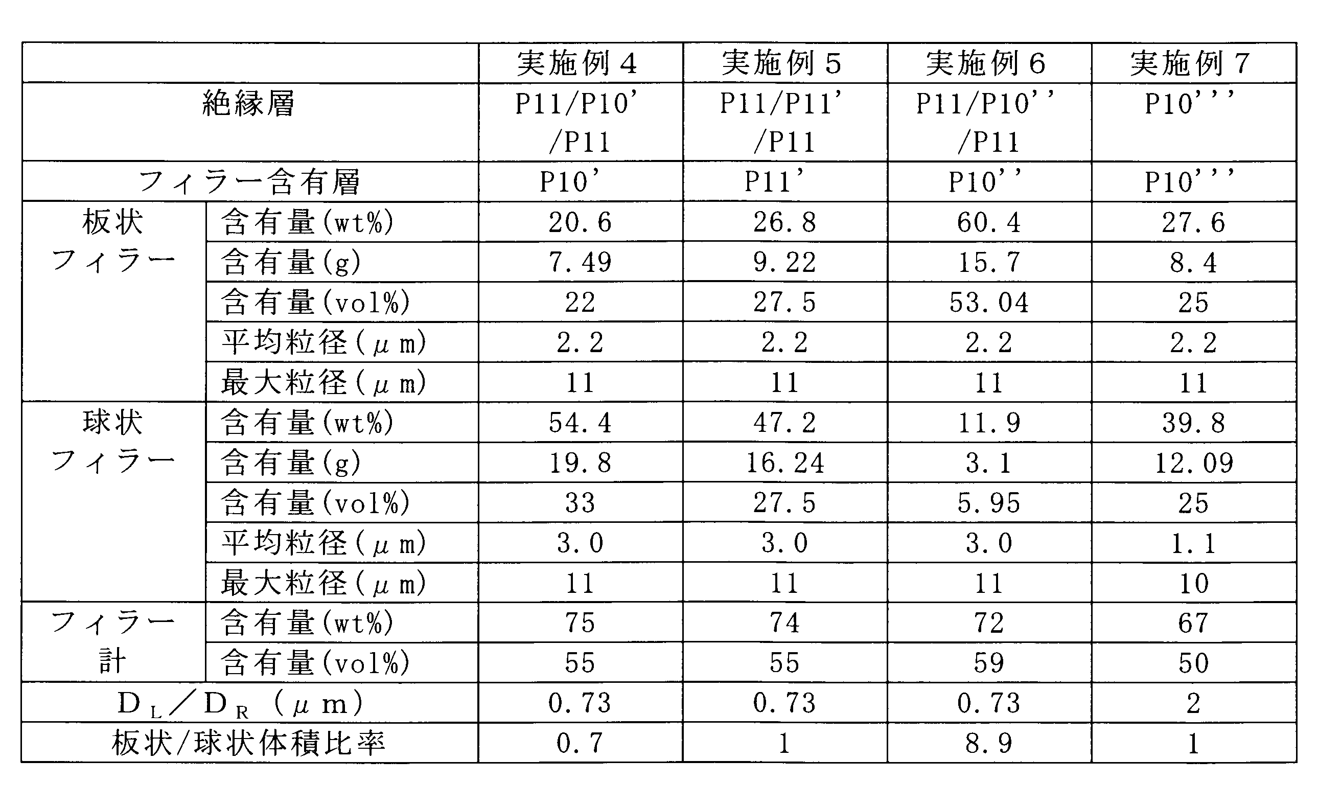
- Example 7 79.5 g of a polyamic acid solution (P10) with a solid content concentration of 12.5 wt%, and boron nitride (made by Denki Kagaku Kogyo Co., Ltd., trade name: SP-3 ′, scale shape, average major axis 2.
- SP-3 ′ boron nitride
- 8.4 g obtained by removing particles exceeding 11 ⁇ m with a classifier and aluminum nitride as a spherical filler (trade name: AlN—H, spherical, average particle diameter 1.1 ⁇ m, manufactured by Tokuyama Corporation) 12 0.09 g was mixed with a centrifugal stirrer until uniform to obtain a polyamic acid resin solution (P10 ′ ′′) containing a thermally conductive filler.
- the polyamic acid resin solution (P10 ′ ′′) containing the above-mentioned heat conductive filler is applied onto an electrolytic copper foil having a thickness of 35 ⁇ m subjected to rust prevention treatment so that the thickness after curing becomes 25 ⁇ m, and 130
- the solvent was removed by heating at 0 ° C. Thereafter, heating was carried out stepwise in a temperature range of 130 to 300 ° C. over 20 minutes to produce a thermally conductive laminate M10 having an insulating layer made of one polyimide layer on a copper foil.
- Table 4 shows the configuration of the insulating layer in the thermally conductive laminate M10.
- the copper foil was removed by etching to produce an insulating film (F6), and CTE, tear propagation resistance, glass transition temperature, heat conduction Each rate was evaluated. The results are shown in Table 5. Furthermore, Table 6 shows the adhesive strength between the insulating layer and the copper foil in the thermally conductive laminate M10.
- the content ratio of the thermally conductive filler in the filler-containing polyimide resin layer is in the range of 35 to 80 vol%
- the maximum particle size of the thermally conductive filler is less than 15 ⁇ m
- the thermally conductive filler contains a plate-like filler and a spherical filler, and the average major axis D L of the plate-like filler is in the range of 0.1 to 2.4 ⁇ m.
- the heat-conductive laminates and heat-conductive polyimide films of Examples 1 to 7 that satisfy the above requirements are excellent in heat conduction characteristics in addition to the heat resistance and dimensional stability of the polyimide resin that is the matrix of the insulating layer. It was.
- the thermally conductive polyimide films and thermally conductive laminates of Examples 1 to 7 can be produced by a commonly performed process such as coating or heat treatment without requiring a special process such as compression of the insulating layer. It was. Therefore, various characteristics required as an insulating layer such as a wiring board are not impaired and can be applied to various electronic devices.
Landscapes
- Chemical & Material Sciences (AREA)
- Engineering & Computer Science (AREA)
- Microelectronics & Electronic Packaging (AREA)
- Health & Medical Sciences (AREA)
- Chemical Kinetics & Catalysis (AREA)
- Medicinal Chemistry (AREA)
- Polymers & Plastics (AREA)
- Organic Chemistry (AREA)
- Laminated Bodies (AREA)
- Compositions Of Macromolecular Compounds (AREA)
Abstract
熱伝導性積層体は、ポリイミド樹脂中に熱伝導性フィラーを含有するフィラー含有ポリイミド樹脂層を少なくとも1層有する絶縁層の片面又は両面に金属層を備えている。前記フィラー含有ポリイミド樹脂層における熱伝導性フィラーの含有割合は35~80vol%であり、熱伝導性フィラーの最大粒子径が15μm未満であるとともに、熱伝導性フィラーとして板状フィラーと球状フィラーを含有し、板状フィラーの平均長径DLが0.1~2.4μmであり、絶縁層の厚み方向での熱伝導率λzが0.8W/mK以上である。
Description
本発明は、フィラーを含有する熱伝導性ポリイミドフィルム及びそれを用いた熱伝導性積層体に関する。
近年、携帯電話、LED照明器具、自動車エンジン周り関連部品に代表されるように電子機器の小型化、軽量化に対する要求が高まってきている。それに伴い、機器の小型化、軽量化に有利なフレキシブル回路基板が電子技術分野において広く使用されるようになってきている。そして、その中でもポリイミド樹脂を絶縁層とするフレキシブル回路基板は、その耐熱性、耐薬品性などが良好なことから、広く用いられている。一方、最近の電子機器の小型化により、回路の集積度が上がってきており、さらに、情報処理の高速化及び信頼性の向上を図るべく、機器内に生じる熱の放熱特性を高めるための技術が注目されている。
電子機器内に生じる熱の放熱特性を高めるには、電子機器の熱伝導性を高めることが有効と考えられる。そのため、配線基板等を構成する絶縁層中に熱伝導性フィラーを含有させる技術が検討されている。より具体的には、絶縁層を形成する樹脂中に、酸化アルミニウム、窒化ホウ素、窒化アルミニウム、窒化ケイ素などの熱伝導性の高い充填材を分散配合することが検討されている。そして、耐熱性の高いポリイミド樹脂に対して熱伝導性フィラーを配合する技術が、例えば特許文献1等で提案されている。
更に、このような熱伝導性フィラーを樹脂に配合する技術を応用して高い熱伝導率を得ることも検討されている。例えば、先に出願人は、樹脂中に、板状熱伝導性フィラーと球状熱伝導性フィラーとを組み合わせて充填した高熱伝導性フィルム及び金属張積層体について提案した(PCT/JP2009/065582)。しかし、この特許出願で提案された技術は、主にフレキシブル性を有する基板への適用を意図したものである。そのため、金属張積層体の可撓性(フレキシブル性)を維持しようとすると、熱伝導性フィラーの配合量を一定量以上には上げられないという点で改善の余地があった。また、粒子径が大きいフィラーを多量に充填すると、樹脂とフィラーの界面にかかる応力が大きくなるため、絶縁層中に空隙が発生してしまい、その点からもフィラーの充填量に限界があった。
このように高熱伝導性フィラーの充填率を高めたり、その粒子径のサイズを大きくしたりする場合には、絶縁層の形成過程で絶縁層中に多くの空隙が発生して、耐電圧性を低下させてしまうという問題があった。一般に、このような高熱伝導性フィラーを含有する絶縁層を形成する場合の多くは、基材上に高熱伝導性フィラーを含有する樹脂溶液を塗布し、乾燥等の熱処理により絶縁層を形成する方法によって行なわれる。熱伝導性樹脂シートの製造方法において、体積配合比を工夫するとともに、乾燥後に圧縮することにより、空隙の発生を抑制しようとする技術が検討されている(例えば、特許文献2を参照)。
しかしながら、絶縁層の圧縮は、その条件によっては絶縁層やこれを備えた積層体の他の特性にも影響を与えるおそれがある。
本発明の目的は、熱伝導性フィラーを絶縁層に多く充填させた場合においても、耐熱性、寸法安定性に加え、熱伝導特性と電気絶縁性にも優れ、金属層と高い接着性を有する熱伝導性ポリイミドフィルム及びそれを用いた熱伝導性積層体を提供することにある。
本発明の熱伝導性積層体は、ポリイミド樹脂中に熱伝導性フィラーを含有するフィラー含有ポリイミド樹脂層を少なくとも1層有する絶縁層と、前記絶縁層の片面又は両面に積層された金属層と、を有するものである。この熱伝導性積層体は、前記フィラー含有ポリイミド樹脂層における熱伝導性フィラーの含有割合が35~80vol%の範囲内であり、前記熱伝導性フィラーの最大粒子径が15μm未満であり、前記熱伝導性フィラーは板状フィラーと球状フィラーとを含有し、前記板状フィラーの平均長径DLが0.1~2.4μmの範囲内であり、前記絶縁層の厚み方向での熱伝導率λzが0.8W/mK以上である。
また、本発明の熱伝導性ポリイミドフィルムは、ポリイミド樹脂中に熱伝導性フィラーを含有するフィラー含有ポリイミド樹脂層を少なくとも1層有するものである。この熱伝導性ポリイミドフィルムは、前記フィラー含有ポリイミド樹脂層における熱伝導性フィラーの含有割合が35~80vol%の範囲内であり、前記熱伝導性フィラーの最大粒子径が15μm未満であり、前記熱伝導性フィラーとして板状フィラーと球状フィラーとを含有し、前記板状フィラーの平均長径DLが0.1~2.4μmの範囲内であり、前記絶縁層の厚み方向での熱伝導率λzが0.8W/mK以上である。
本発明の熱伝導性ポリイミドフィルム及び熱伝導性積層体によれば、絶縁層のマトリックスとなるポリイミド樹脂の有する耐熱性、寸法安定性に加え、熱伝導特性にも優れている。また、絶縁層中に多量に熱伝導性フィラーを含有する場合でも、絶縁層中の空隙の発生が抑制又は低減されることで耐電圧性にも優れている。さらに、本発明の熱伝導性ポリイミドフィルム及び熱伝導性積層体は、絶縁層の圧縮などの特別な工程を必要とせずに、通常行われる、塗布や、熱処理などの工程によって作製できるので有利である。
[熱伝導性積層体]
本発明の実施の形態に係る熱伝導性積層体は、絶縁層とその片面又は両面に有する金属層からなる。絶縁層はポリイミド樹脂から構成され、少なくとも1層はポリイミド樹脂中に熱伝導性フィラーを含有するフィラー含有ポリイミド樹脂層である。絶縁層はフィラー含有ポリイミド樹脂層のみからなっていてもよく、フィラーを含有しないポリイミド樹脂層を有してもよい。フィラーを含有しないポリイミド樹脂層を有する場合、その厚みは、例えば、フィラー含有ポリイミド樹脂層の1/100~1/2の範囲内、好ましくは1/20~1/3の範囲内とすることがよい。フィラーを含有しないポリイミド樹脂層を有する場合、そのポリイミド樹脂層が金属層に接するようにすれば、金属層と絶縁層の接着性が向上する。
本発明の実施の形態に係る熱伝導性積層体は、絶縁層とその片面又は両面に有する金属層からなる。絶縁層はポリイミド樹脂から構成され、少なくとも1層はポリイミド樹脂中に熱伝導性フィラーを含有するフィラー含有ポリイミド樹脂層である。絶縁層はフィラー含有ポリイミド樹脂層のみからなっていてもよく、フィラーを含有しないポリイミド樹脂層を有してもよい。フィラーを含有しないポリイミド樹脂層を有する場合、その厚みは、例えば、フィラー含有ポリイミド樹脂層の1/100~1/2の範囲内、好ましくは1/20~1/3の範囲内とすることがよい。フィラーを含有しないポリイミド樹脂層を有する場合、そのポリイミド樹脂層が金属層に接するようにすれば、金属層と絶縁層の接着性が向上する。
<熱伝導性フィラー>
本発明において、フィラー含有ポリイミド樹脂層には、熱伝導性フィラーとして板状フィラーと球状フィラーとを用いる。この層における熱伝導性フィラーの体積比率(含有量又は含有割合ともいう)は、熱伝導性積層体に優れた熱伝導性を付与するため、板状フィラーと球状フィラーとの合計量で35~80vol%の範囲内、好ましくは50~70vol%の範囲内、より好ましくは55~65vol%の範囲内、最も好ましくは55~59vol%の範囲内である。熱伝導性フィラーの含有割合が35vol%に満たないと、熱伝導特性が低くなり、放熱材料として十分な特性を得ることができない。また、熱伝導性フィラーの含有割合が80vol%を超えると、絶縁層が脆くなり、取り扱いにくくなるばかりでなく、絶縁層をポリアミド酸溶液から形成しようとする場合、ワニスの粘度が高くなり、作業性も低下する。
本発明において、フィラー含有ポリイミド樹脂層には、熱伝導性フィラーとして板状フィラーと球状フィラーとを用いる。この層における熱伝導性フィラーの体積比率(含有量又は含有割合ともいう)は、熱伝導性積層体に優れた熱伝導性を付与するため、板状フィラーと球状フィラーとの合計量で35~80vol%の範囲内、好ましくは50~70vol%の範囲内、より好ましくは55~65vol%の範囲内、最も好ましくは55~59vol%の範囲内である。熱伝導性フィラーの含有割合が35vol%に満たないと、熱伝導特性が低くなり、放熱材料として十分な特性を得ることができない。また、熱伝導性フィラーの含有割合が80vol%を超えると、絶縁層が脆くなり、取り扱いにくくなるばかりでなく、絶縁層をポリアミド酸溶液から形成しようとする場合、ワニスの粘度が高くなり、作業性も低下する。
また、本発明では、絶縁層中に空隙が生じることを抑制又は低減して、耐電圧特性を高いものとするために、フィラー含有ポリイミド樹脂層における板状フィラーの体積比率(A)は、球状フィラーの体積比率(B)よりも大きくすることが好ましい。具体的には、(A)/(B)が1~15の範囲内であることがより好ましく、1.5~15の範囲内となるようにすることが最も好ましい。
ここで、板状フィラーとは、フィラー形状が板状、燐片状のフィラーで、平均厚みが、表面部の平均長径又は平均短径より十分に小さいもの(好ましくは1/2以下)をいう。本発明で使用する板状フィラーは、平均長径DLが0.1~2.4μmの範囲内のものである。平均長径DLが0.1μmに満たないと、熱伝導率が低く、熱膨張係数が大きくなり、板状の効果が小さくなってしまう。平均長径DLが2.4μmを超えると製膜時に応力の集中により空隙が発生しやすくなる。ここで、平均長径DLとは、板状フィラーの長手直径の平均値を意味する。板状フィラーの好ましい具体例としては、窒化ホウ素、酸化アルミニウム等が挙げられ、これらを単独で又は2種以上併用して使用することもできる。また、板状フィラーの平均長径DLは、0.5~2.2μmの範囲内にあることが高熱伝導の点から好ましい。本発明に用いる板状フィラーの最適なものは、平均長径DLが1~2.2μmの窒化ホウ素である。なお、平均径はメディアン径を意味し、モード径は上記範囲で1つであることがよく、これは球状フィラーについても同様である。
また、球状フィラーとは、フィラー形状が球状及び球状に近いもので、平均長径と平均短径の比が1又は1に近いもの(好ましくは0.8以上)をいう。本発明で使用する球状フィラーの平均粒径DRは、0.05~5.0μmの範囲内が好ましい。平均粒径DRが0.05μmに満たないと、熱伝導性向上の効果が小さくなる。また、球状フィラーの平均粒径DRが5μmを超えると、球状フィラーが板状フィラーの層間に入りづらくなったり、周辺の樹脂収縮による応力の増加で空隙が発生したりして、発明効果の制御が難しくなる。ここで、平均粒径DRとは、球状フィラー粒子の直径の平均値(メディアン径)を意味する。球状フィラーの好ましい具体例としては、例えば酸化アルミニウム、溶融シリカ、窒化アルミニウムが挙げられ、これらを単独で又は2種以上併用して使用することもできる。例えば、酸化アルミニウムは耐湿性に優れている点で好ましいものであり、窒化アルミニウムは絶縁層に高い熱伝導性を付与できる点において好ましいものである。従って、熱伝導性積層体の用途に応じて上記球状フィラーの材質を選定し、必要に応じて組み合わせて使用することができる。また、球状フィラーの平均粒径DRは、0.1~4.0μmの範囲内にあることが充填性向上の点から好ましい。本発明に用いる球状フィラーの最適なものは、平均粒径DRが0.5~3.0μmの範囲内の酸化アルミニウムである。酸化アルミニウムは熱伝導率が劣るが、板状フィラーと球状フィラーの両方を使用することにより、この欠点は解消される。ただし、より高い熱伝導率を望む場合は、板状フィラーと球状フィラーのいずれか又は両方は、酸化アルミニウム以外のフィラーとすることが好ましい。
なお、本発明でいう熱伝導性フィラーは、熱伝導率が5.0W/m・K以上であることがよい。熱伝導性フィラーの5.0W/mK未満になると、積層体とした場合の放熱効果が薄れる。
また、熱伝導性フィラー中、球状フィラーの含有割合は、熱伝導率向上と耐電圧向上の両立の観点から、25~70wt%の範囲とすることが好ましい。なお、フィラーを含有しないポリイミド樹脂層を有する場合、全絶縁層中の熱伝導性フィラーの含有率は好ましくは30~90wt%の範囲、より好ましくは30~85wt%、更に好ましくは30~60wt%とすることがよい。
熱伝導性フィラーは、上記平均長径DLと平均粒径DRとの関係がDL>DR/2であり、30μm以上の熱伝導フィラーを含有しないことが好ましい。平均長径DLと平均粒径DRとの関係がDL>DR/2の要件を満たさないと、熱伝導率の低下を招くこととなる。また、30μm以上の熱伝導フィラーを含有すると、表面の外観不良が生じる傾向になる。平均長径DLと平均粒径DRとの関係はDL>DRであることがより好ましい。範囲としては、DRはDLの1/3~5/3の範囲であることが好ましい。
また、使用する熱伝導性フィラー中の粒径9μm以上のフィラーが、全体の50wt%以下とすることが好ましく、特には、板状フィラー中における粒径9μm以上のフィラーの割合を50wt%以下とすることが好ましい。このことにより、絶縁層表面の凹凸がなくなり平滑な表面とすることができる。ここで、板状フィラーの場合の粒径は、長径を意味する。
また、本発明で使用する熱伝導性フィラーの最大粒子径は15μm未満とする必要がある。この最大粒子径が15μm以上となると、絶縁層表面の凹凸が発生したり、フィラーと樹脂の界面に空隙が発生しやすくなる。ここで、板状フィラーの場合の最大粒子径は、長径を意味する。なお、本発明において、上記熱伝導性フィラーは、いずれも市販品を適宜選定して用いることができる。
<絶縁層>
本発明で絶縁層のマトリックス樹脂となるポリイミド樹脂は、一般的に下記一般式(1)で表される。このようなポリイミド樹脂は、ジアミン成分と酸二無水物成分とを実質的に等モル使用し、有機極性溶媒中で重合する公知の方法によって製造することができる。この場合、粘度を所望の範囲とするために、ジアミン成分に対する酸二無水物成分のモル比を調整してもよく、その範囲は、例えば0.980~1.03のモル比範囲が好ましい。
本発明で絶縁層のマトリックス樹脂となるポリイミド樹脂は、一般的に下記一般式(1)で表される。このようなポリイミド樹脂は、ジアミン成分と酸二無水物成分とを実質的に等モル使用し、有機極性溶媒中で重合する公知の方法によって製造することができる。この場合、粘度を所望の範囲とするために、ジアミン成分に対する酸二無水物成分のモル比を調整してもよく、その範囲は、例えば0.980~1.03のモル比範囲が好ましい。

酸二無水物としては、例えば、O(OC)2-Ar1-(CO)2Oによって表される芳香族テトラカルボン酸二無水物が好ましく、下記芳香族酸無水物残基をAr1として与えるものが例示される。

酸二無水物は、単独で又は2種以上混合して用いることができる。これらの中でも、ピロメリット酸二無水物(PMDA)、3,3',4,4'-ビフェニルテトラカルボン酸二無水物(BPDA)、3,3',4,4'-ベンゾフェノンテトラカルボン酸二無水物(BTDA)、3,3',4,4'-ジフェニルスルホンテトラカルボン酸二無水物(DSDA)、及び4,4'-オキシジフタル酸二無水物(ODPA)から選ばれるものを使用することが好ましい。
ジアミンとしては、例えば、H2N-Ar2-NH2によって表される芳香族ジアミンが好ましく、下記芳香族ジアミン残基をAr2として与える芳香族ジアミンが例示される。

これらのジアミンの中でも、ジアミノジフェニルエーテル(DAPE)、2,2'-ジメチル-4,4'-ジアミノビフェニル(m-TB)、パラフェニレンジアミン(p-PDA)、1,3-ビス(4-アミノフェノキシ)ベンゼン(TPE-R)、1,3-ビス(3-アミノフェノキシ)ベンゼン(APB)、1,4-ビス(4-アミノフェノキシ)ベンゼン(TPE-Q)、及び2,2-ビス[4-(4-アミノフェノキシ)フェニル]プロパン(BAPP)が好適なものとして例示される。
ジアミン成分と酸二無水物成分との重合に用いる溶媒については、例えばジメチルアセトアミド、n-メチルピロリジノン、2-ブタノン、ジグライム、キシレン等を挙げることができ、これらについては1種若しくは2種以上を併用して使用することもできる。また、重合して得られたポリアミド酸(ポリイミド前駆体)の樹脂粘度については、500cps~35000cpsの範囲内とすることが好ましく、1000cps~10000cpsの範囲内とすることが特に好ましい。
本発明の熱伝導性積層体の絶縁層を形成する方法は、特に限定されるものではなく公知の手法を採用することができる。ここでは、その最も代表的な例を示す。まず、絶縁層の原料である、熱伝導性フィラーを含有するポリアミド酸の樹脂溶液を、金属層である銅箔等の金属箔上に直接流延塗布して塗布膜を形成する。ここで、ポリアミド酸は、ポリイミドの前駆体樹脂である。次に、塗布膜を150℃以下の温度である程度溶媒を乾燥除去する。その後、塗布膜に対し、更にイミド化のために100~400℃、好ましくは130~360℃の温度範囲で5~30分間程度の熱処理を行う。このようにして、金属層上に熱伝導性フィラーを含有するポリイミド樹脂からなる絶縁層を形成することができる。絶縁層を2層以上のポリイミド層とする場合、第一のポリアミド酸の樹脂溶液を塗布、乾燥したのち、第二のポリアミド酸の樹脂溶液を塗布、乾燥する。それ以降は、同様にして第三のポリアミド酸の樹脂溶液、次に、第4のポリアミド酸の樹脂溶液、・・・というように、ポリアミド酸の樹脂溶液を、必要な回数だけ、順次、塗布し、乾燥する。その後、まとめて100~400℃の温度範囲で5~30分間程度の熱処理を行って、イミド化を行うことがよい。熱処理の温度が100℃より低いとポリイミドの脱水閉環反応が十分に進行せず、反対に400℃を超えると、ポリイミド樹脂層及び銅箔が酸化等により劣化するおそれがある。
また、絶縁層を形成する別の例を挙げる。まず、任意の支持基体上に、絶縁層の原料である、熱伝導性フィラーを含有するポリアミド酸の樹脂溶液を流延塗布してフィルム状に成型する。このフィルム状成型物を、支持体上で加熱乾燥することにより自己支持性を有するゲルフィルムとする。その後、ゲルフィルムを支持体より剥離した後、更に高温で熱処理し、イミド化させてポリイミドフィルムとする。このポリイミドフィルムを絶縁層とした熱伝導性積層体とするには、例えば、ポリイミドフィルムに直接、又は任意の接着剤を介して金属箔を加熱圧着する方法や、金属蒸着等の手法によってポリイミドフィルムに金属層を形成する方法が一般的である。
上記絶縁層の形成において用いられる、熱伝導性フィラーを含有するポリアミド酸の樹脂溶液の調製に際しては、例えばポリアミド酸の樹脂溶液に熱伝導性フィラーを直接配合してもよい。あるいは、フィラー分散性を考慮し、ポリアミド酸の樹脂溶液の原料(酸二無水物成分又はジアミン成分)の一方を投入した反応溶媒に予め熱伝導性フィラーを配合した後、攪拌下にもう一方の原料を投入して重合を進行させてもよい。直接配合の場合は一回でフィラーを全量投入してもよいし、数回分けて少しずつ添加してもよい。また、樹脂溶液の原料も一括で入れてもよいし、数回に分けて少しずつ混合してもよい。
絶縁層は、単層からなるものであってもよいし、複数層からなるものであってもよい。例えば、熱伝導性積層体の寸法安定性や、銅箔との接着強度を優れたものとするために、複数層とすることもできる。ここで、絶縁層を複数層とする場合、熱伝導性を考慮するとすべての層に熱伝導性フィラーを含有させることが好ましい。ただし、フィラー含有ポリイミド樹脂層の隣接層を、フィラーを含有しない層とするか、あるいはその含有量が低い層とすることにより、加工時等のフィラーの滑落が防止できるという有利な効果をもたせることができる。なお、本発明は、フィラー含有ポリイミド樹脂層と金属箔とを接着するための接着剤を用いることを除外するものではない。ただし、絶縁層の両面に金属層を有する熱伝導性積層体において接着層を介在させる場合には、接着層の厚みは、熱伝導性を損なわないように、全絶縁層の厚みの30%未満とすることが好ましく、20%未満とすることがより好ましい。また、絶縁層の片面のみに金属層を有する熱伝導性積層体において接着層を介在させる場合には、接着層の厚みは、熱伝導性を損なわないように、全絶縁層の厚みの15%未満とすることが好ましく、10%未満とすることがより好ましい。そして、接着剤層は絶縁層の一部を構成するので、ポリイミド樹脂層であることが好ましい。絶縁層の主たる材質であるにおけるポリイミド樹脂のガラス転移温度は、耐熱性を付与する観点から300℃以上とすることが好ましい。ガラス転移温度を300℃以上とするには、ポリイミド樹脂を構成する上記の酸二無水物やジアミン成分を適宜選択することで可能となる。
本発明の熱伝導性積層体において、絶縁層の厚さは、例えば10~100μmの範囲内であることが好ましく、12~50μmの範囲内がより好ましい。絶縁層の厚みが10μmに満たないと、熱伝導性積層体の製造時の搬送工程で金属箔にシワが入るなどの不具合が生じやすくなる。反対に、絶縁層の厚みが100μmを超えると高い熱伝導性の発現や、屈曲性等の点で不利になる傾向となる。絶縁層の耐電圧は、2kV以上とすることが好ましい。
絶縁層の熱膨張係数(CTE)は、例えば5×10⁻⁶~30×10-6/K(5~30ppm/K)の範囲内にあることが好ましく、10×10-6~25×10-6/K(10~25ppm/K)の範囲内がより好ましい。絶縁層の熱膨張係数が5×10-6/Kより小さいと、熱伝導積層体とした後でカールが生じやすくハンドリング性に劣る。一方、絶縁層の熱膨張係数が30×10-6/Kを超えると、フレキシブル基板など電子材料としての寸法安定性に劣り、また耐熱性も低下する傾向にある。
本発明における絶縁層の厚み方向での熱伝導率λzは、0.8W/mK以上とする必要があり、1.0W/mK以上とすることが好ましく、1.5W/mK以上とすることがより好ましい。熱伝導率λzが0.8W/mKに満たないと、放熱用途への適用を主目的とする本発明の熱伝導性積層体において、目的を達することができない。この熱伝導率特性と他の構成要件を充足することで、他の諸特性をも同時に満足する熱伝導性積層体が得られる。特に、熱伝導率λzが1.0W/mKであると、優れた放熱特性が得られ、例えば放熱基板の他、多くの用途へ適用可能な熱伝導性積層体とすることができる。また、絶縁層の熱伝導率は、平面方向で1.0W/mK以上であることが有利であり、2.0W/mK以上であることが好ましい。
上記したとおり、本発明の熱伝導性積層体は、絶縁層の片面側のみに金属層を備えたものであってもよいし、絶縁層の両面に金属層を備えたものであってもよい。なお、両面に金属層を備えた熱伝導性積層体は、例えば、片面金属層の積層体を形成した後、互いにポリイミド樹脂層を向き合わせて熱プレスによって圧着し形成する方法や、片面金属層の積層体のポリイミド樹脂層に金属箔を圧着し形成する方法等により得ることができる。
<金属層>
金属層は、上記したように金属箔からなるものであってもよいし、フィルムに金属蒸着したものであってもよい。また、熱伝導性フィラーを含有するポリイミド前駆体を直接塗布可能な点からは、金属箔でも金属板でも可能であり、中でも銅箔若しくは銅板が好ましい。金属層の厚みは、例えば5μm~3mmの範囲内が好ましく、12μm~1mmの範囲内がより好ましい。金属層の厚みが5μmに満たないと、積層基板製造等における搬送時にシワが入るなどの不具合が生じるおそれがある。反対に金属層の厚みが3mmを超えると硬くて加工性が悪くなる。金属層の厚みについては、一般的に、車載用途では厚いものが適し、LED用途などでは薄い金属層が適する。
金属層は、上記したように金属箔からなるものであってもよいし、フィルムに金属蒸着したものであってもよい。また、熱伝導性フィラーを含有するポリイミド前駆体を直接塗布可能な点からは、金属箔でも金属板でも可能であり、中でも銅箔若しくは銅板が好ましい。金属層の厚みは、例えば5μm~3mmの範囲内が好ましく、12μm~1mmの範囲内がより好ましい。金属層の厚みが5μmに満たないと、積層基板製造等における搬送時にシワが入るなどの不具合が生じるおそれがある。反対に金属層の厚みが3mmを超えると硬くて加工性が悪くなる。金属層の厚みについては、一般的に、車載用途では厚いものが適し、LED用途などでは薄い金属層が適する。
[熱伝導性ポリイミドフィルム]
本発明の実施の形態に係る熱伝導性ポリイミドフィルムは、本発明の熱伝導性積層体における絶縁層と同様の構成を採り、その詳細は、上記した本発明の熱伝導性積層体の絶縁層の説明が参照される。すなわち、上述した熱伝導性積層体から金属層を除去して得られる絶縁層のフィルムは、本発明の熱伝導性ポリイミドフィルムと同様の構成となる。また、本発明の熱伝導性積層体は、本発明の熱伝導性ポリイミドフィルムを絶縁層として有するものということもできる。
本発明の実施の形態に係る熱伝導性ポリイミドフィルムは、本発明の熱伝導性積層体における絶縁層と同様の構成を採り、その詳細は、上記した本発明の熱伝導性積層体の絶縁層の説明が参照される。すなわち、上述した熱伝導性積層体から金属層を除去して得られる絶縁層のフィルムは、本発明の熱伝導性ポリイミドフィルムと同様の構成となる。また、本発明の熱伝導性積層体は、本発明の熱伝導性ポリイミドフィルムを絶縁層として有するものということもできる。
熱伝導性積層体の製造方法において、その絶縁層の形成は、金属層を支持基材として、その上に絶縁層を形成できると説明をしたが、本発明の熱伝導性ポリイミドフィルムの製造にあたって使用する支持基材は、特に限定されるものではなく、任意の材質の基材を用いることができる。また、熱伝導性ポリイミドフィルムの形成にあたっては、基材上で完全にイミド化を完了させた樹脂フィルムを形成する必要はない。例えば、半硬化状態のポリイミド前駆体状態での樹脂フィルムを支持基材から剥離等の手段で分離し、分離後イミド化を完了させて熱伝導性ポリイミドフィルムとすることもできる。これらの点以外は、上述したとおり、本発明の熱伝導性積層体の絶縁層の説明が参照されるので、その説明は省略する。
以下、実施例に基づいて本発明を具体的に示すが、本発明はこれらの実施例に限定されるものではない。
本実施例に用いた略号を以下に示す。
m-TB:2,2'-ジメチル-4,4'-ジアミノビフェニル
TPE-R:1,3-ビス(4-アミノフェノキシ)ベンゼン
BAPP:2,2-ビス[4-(4-アミノフェノキシ)フェニル]プロパン
PMDA:ピロメリット酸二無水物
BPDA:3,3',4,4’-ビフェニルテトラカルボン酸二無水物
DMAc:N,N-ジメチルアセトアミド
DAPE:4,4'-ジアミノジフェニルエーテル
m-TB:2,2'-ジメチル-4,4'-ジアミノビフェニル
TPE-R:1,3-ビス(4-アミノフェノキシ)ベンゼン
BAPP:2,2-ビス[4-(4-アミノフェノキシ)フェニル]プロパン
PMDA:ピロメリット酸二無水物
BPDA:3,3',4,4’-ビフェニルテトラカルボン酸二無水物
DMAc:N,N-ジメチルアセトアミド
DAPE:4,4'-ジアミノジフェニルエーテル
また、実施例において評価した各特性については、下記評価方法に従った。
[厚さ方向熱伝導率(λz)]
測定対象のフィルム(絶縁フィルム、以下同じ)を20mm×20mmのサイズに切り出し、レーザーフラッシュ法による厚さ方向の熱拡散率(ブルカー・エイエックスエス製LFA 447 Nanoflash装置)、DSC(示差走査熱量測定)による比熱、気体置換法による密度をそれぞれ測定し、これらの結果をもとに熱伝導率を算出した。
[厚さ方向熱伝導率(λz)]
測定対象のフィルム(絶縁フィルム、以下同じ)を20mm×20mmのサイズに切り出し、レーザーフラッシュ法による厚さ方向の熱拡散率(ブルカー・エイエックスエス製LFA 447 Nanoflash装置)、DSC(示差走査熱量測定)による比熱、気体置換法による密度をそれぞれ測定し、これらの結果をもとに熱伝導率を算出した。
[熱膨張係数(CTE)]
3mm×15mmのサイズの絶縁フィルムを、熱機械分析(TMA)装置にて5gの荷重を加えながら一定の昇温速度(20℃/min)で30℃から260℃の温度範囲で引張り試験を行い、温度に対する絶縁フィルムの伸び量から熱膨張係数(ppm/K)を測定した。
3mm×15mmのサイズの絶縁フィルムを、熱機械分析(TMA)装置にて5gの荷重を加えながら一定の昇温速度(20℃/min)で30℃から260℃の温度範囲で引張り試験を行い、温度に対する絶縁フィルムの伸び量から熱膨張係数(ppm/K)を測定した。
[ガラス転移温度(Tg)]
絶縁フィルム(10mm×22.6mm)を動的熱機械分析装置にて20℃から500℃まで5℃/分で昇温させたときの動的粘弾性を測定し、ガラス転移温度(tanδ極大値:℃)を求めた。
絶縁フィルム(10mm×22.6mm)を動的熱機械分析装置にて20℃から500℃まで5℃/分で昇温させたときの動的粘弾性を測定し、ガラス転移温度(tanδ極大値:℃)を求めた。
[接着強度]
耐電圧を測定するためのサンプル加工(回路加工)に耐えられる程度に銅箔と樹脂層が密着しているサンプルは○(良好)とし、加工中もしくは評価中に樹脂層が銅箔から剥離するサンプルは×(不良)とした。また、実施例4~6の接着力は、テンションテスターを用い、幅1mmの銅張品の樹脂側を両面テープによりアルミ板に固定し、銅を180°方向に50mm/minの速度で剥離してピール強度を求めた。
耐電圧を測定するためのサンプル加工(回路加工)に耐えられる程度に銅箔と樹脂層が密着しているサンプルは○(良好)とし、加工中もしくは評価中に樹脂層が銅箔から剥離するサンプルは×(不良)とした。また、実施例4~6の接着力は、テンションテスターを用い、幅1mmの銅張品の樹脂側を両面テープによりアルミ板に固定し、銅を180°方向に50mm/minの速度で剥離してピール強度を求めた。
[耐電圧]
熱伝導性積層体を5cm×5cmのサイズでカットし、片側の銅箔を直径2cm円状に加工し、不要部分は銅箔エッチング液で除去した。JIS C2110に基づき、KIKUSUI製TOS 5101装置にて、段階昇圧法により絶縁油中にて耐電圧を測定した。0.2kV刻みで電圧をステップ上昇させ、各電圧において20秒保持し、漏れ電流8.5mAとし、破壊した電圧の一つ前の値を初期耐電圧とした。電極のサイズは2cmφである。サンプルを120℃/95RH%湿度の環境に24時間保持後、測定した耐電圧を湿熱後耐電圧とした。
熱伝導性積層体を5cm×5cmのサイズでカットし、片側の銅箔を直径2cm円状に加工し、不要部分は銅箔エッチング液で除去した。JIS C2110に基づき、KIKUSUI製TOS 5101装置にて、段階昇圧法により絶縁油中にて耐電圧を測定した。0.2kV刻みで電圧をステップ上昇させ、各電圧において20秒保持し、漏れ電流8.5mAとし、破壊した電圧の一つ前の値を初期耐電圧とした。電極のサイズは2cmφである。サンプルを120℃/95RH%湿度の環境に24時間保持後、測定した耐電圧を湿熱後耐電圧とした。
合成例1
窒素気流下で、m-TB(12.4591g、0.0587mol)及びDAPE(9.6152g、0.0480mol)を500mlのセパラブルフラスコの中で攪拌しながら溶剤DMAc255g中に溶解させた。次いで、そこにPMDA(22.9258g、0.1051mol)を加えた。その後、溶液を室温で3時間攪拌を続けて重合反応を行い、茶褐色の粘稠なポリアミド酸溶液(P1)を得た。
窒素気流下で、m-TB(12.4591g、0.0587mol)及びDAPE(9.6152g、0.0480mol)を500mlのセパラブルフラスコの中で攪拌しながら溶剤DMAc255g中に溶解させた。次いで、そこにPMDA(22.9258g、0.1051mol)を加えた。その後、溶液を室温で3時間攪拌を続けて重合反応を行い、茶褐色の粘稠なポリアミド酸溶液(P1)を得た。
合成例2
窒素気流下で、BAPP(23.2045g、0.0565mol)を500mlのセパラブルフラスコの中で攪拌しながら溶剤DMAc264g中に溶解させた。次いで、PMDA(11.9473g、0.0548mol)、BPDA(0.8482g、0.0029mol)を加えた。その後、溶液を室温で3時間攪拌を続けて重合反応を行い、茶褐色の粘稠なポリアミド酸溶液(P2)を得た。
窒素気流下で、BAPP(23.2045g、0.0565mol)を500mlのセパラブルフラスコの中で攪拌しながら溶剤DMAc264g中に溶解させた。次いで、PMDA(11.9473g、0.0548mol)、BPDA(0.8482g、0.0029mol)を加えた。その後、溶液を室温で3時間攪拌を続けて重合反応を行い、茶褐色の粘稠なポリアミド酸溶液(P2)を得た。
合成例3
窒素気流下で、m-TB(19.1004g、0.08997mol)及びTPE-R(2.9224g、0.0100mol)を500mlのセパラブルフラスコの中で攪拌しながら溶剤DMAc255g中に溶解させた。次いで、PMDA(17.1827g、0.07878mol)を加えて、10分攪拌後、追加してBPDA(5.7944g、0.0197mol)を添加した。その後、溶液を室温で4時間攪拌を続けて重合反応を行い、茶褐色の粘稠なポリアミド酸溶液(P3)を得た。
窒素気流下で、m-TB(19.1004g、0.08997mol)及びTPE-R(2.9224g、0.0100mol)を500mlのセパラブルフラスコの中で攪拌しながら溶剤DMAc255g中に溶解させた。次いで、PMDA(17.1827g、0.07878mol)を加えて、10分攪拌後、追加してBPDA(5.7944g、0.0197mol)を添加した。その後、溶液を室温で4時間攪拌を続けて重合反応を行い、茶褐色の粘稠なポリアミド酸溶液(P3)を得た。
実施例1
ポリアミド酸溶液(P1)65.242gと、板状フィラーとして市販の窒化ホウ素(鱗片形状、平均長径2.2μm、最大粒径11μm)18.16gと、球状フィラーとして市販のアルミナ(球状、平均粒子径3μm、最大粒径10μm)3.55gとを均一になるまで遠心攪拌機で混合した。その後粘度調整のためDMAc13.048gを添加し、再度均一になるまで遠心攪拌機で混合し、熱伝導性フィラーを含有するポリアミド酸溶液(P4)を得た。
厚さ35μmの電解銅箔上に、フィラーを配合していないポリアミド酸溶液(P2)を硬化後の厚みが2.0μmとなるように塗布し、130℃で加熱乾燥し溶剤を除去した。次に、板状フィラーと球状フィラーを混合した熱伝導性フィラーを含有するポリアミド酸(P4)の溶液を硬化後の厚みが22μmとなるように塗布し、130℃で加熱乾燥し溶剤を除去した。さらに、その上にフィラーを配合していないポリアミド酸溶液(P2)を硬化後の厚みが2.0μmとなるように塗布し、130℃で加熱乾燥し溶剤を除去した。その後、130~300℃の温度範囲で、段階的に20分かけて昇温加熱して、銅箔上に3層のポリイミド層からなる絶縁層を有する熱伝導性積層体M1(P2/P4/P2)を作製した。
得られた熱伝導性積層体M1における絶縁層の特性を評価するために銅箔をエッチング除去して絶縁フィルムを作製し、熱伝導率、CTE、Tgをそれぞれ評価した。結果を表2に示す。更に、熱伝導性積層体における金属-絶縁樹脂層の接着強度、初期及び湿熱後の耐電圧を測定した。結果を表3に示す。
なお、特に断らない限り、以下に示す実施例及び比較例で得られた絶縁フィルム及び熱伝導性積層体についても、実施例1と同様の項目の評価を行なった。
実施例2
ポリアミド酸溶液(P1)54.092gと、板状フィラーとして実施例1と同じ窒化ホウ素12.71gと、球状フィラーとして実施例1と同じアルミナ22.38gとを均一になるまで遠心攪拌機で混合した。その後粘度調整のためDMAc10.818gを添加し、再度均一になるまで遠心攪拌機で混合し、熱伝導性フィラーを含有するポリアミド酸溶液(P5)を得た。
厚さ500μmの銅箔を用いて、実施例1と同様にして硬化後の厚み構成が2.0μm/24μm/2.0μmである熱伝導性積層体M2(P2/P5/P2)を作製した。
得られた熱伝導性積層体M2を用い、実施例1と同様の方法で絶縁フィルムを作製し、絶縁フィルムの特性を評価するとともに、熱伝導性積層体についても評価した。それぞれの評価結果を表2及び表3に示す。
実施例3
ポリアミド酸溶液(P2)78.98gと、板状フィラーとして実施例1と同じ窒化ホウ素17.58gと、球状フィラーとして実施例1と同じアルミナ3.44gとを均一になるまで遠心攪拌機で混合し、熱伝導性フィラーを含有するポリアミド酸溶液(P6)を得た。
厚さ35μmの銅箔を用いて、実施例1と同様にして硬化後の厚み構成が2.0μm/21μm/2.0μmである熱伝導性積層体M3(P2/P6/P2)を作製した。
ポリアミド酸溶液(P2)78.98gと、板状フィラーとして実施例1と同じ窒化ホウ素17.58gと、球状フィラーとして実施例1と同じアルミナ3.44gとを均一になるまで遠心攪拌機で混合し、熱伝導性フィラーを含有するポリアミド酸溶液(P6)を得た。
厚さ35μmの銅箔を用いて、実施例1と同様にして硬化後の厚み構成が2.0μm/21μm/2.0μmである熱伝導性積層体M3(P2/P6/P2)を作製した。
比較例1
ポリアミド酸溶液(P3)86.96gと、板状フィラーとして窒化ホウ素(市販品:鱗片形状、平均長径4.5μm、最大粒径20μm)6.52gと、球状フィラーとして実施例1と同じアルミナ6.52gとを均一になるまで遠心攪拌機で混合し、熱伝導性フィラーを含有するポリアミド酸溶液(P7)を得た。
厚さ12μmの銅箔を用いて、実施例1と同様に硬化後の厚み構成が2.0μm/21μm/2.0μmである熱伝導性積層体M4(P2/P7/P2)を作製した。
ポリアミド酸溶液(P3)86.96gと、板状フィラーとして窒化ホウ素(市販品:鱗片形状、平均長径4.5μm、最大粒径20μm)6.52gと、球状フィラーとして実施例1と同じアルミナ6.52gとを均一になるまで遠心攪拌機で混合し、熱伝導性フィラーを含有するポリアミド酸溶液(P7)を得た。
厚さ12μmの銅箔を用いて、実施例1と同様に硬化後の厚み構成が2.0μm/21μm/2.0μmである熱伝導性積層体M4(P2/P7/P2)を作製した。
比較例2
ポリアミド酸溶液(P3)86.96gと、板状フィラーとして窒化ホウ素(市販品:鱗片形状、平均長径2.5μm、最大粒径11μm、)6.52gと、球状フィラーとして実施例1と同じアルミナ6.52gとを均一になるまで遠心攪拌機で混合し、熱伝導性フィラーを含有するポリアミド酸溶液(P8)を得た。
厚さ12μmの銅箔を用いて、実施例1と同様に硬化後の厚み構成が2.0μm/21μm/2.0μmである熱伝導性積層体M5(P2/P8/P2)を作製した。
ポリアミド酸溶液(P3)86.96gと、板状フィラーとして窒化ホウ素(市販品:鱗片形状、平均長径2.5μm、最大粒径11μm、)6.52gと、球状フィラーとして実施例1と同じアルミナ6.52gとを均一になるまで遠心攪拌機で混合し、熱伝導性フィラーを含有するポリアミド酸溶液(P8)を得た。
厚さ12μmの銅箔を用いて、実施例1と同様に硬化後の厚み構成が2.0μm/21μm/2.0μmである熱伝導性積層体M5(P2/P8/P2)を作製した。
比較例3
ポリアミド酸溶液(P3)61.467gと、板状フィラーとして比較例1と同じ窒化ホウ素9.50gと、球状フィラーとして実施例1と同じアルミナ16.74gとを均一になるまで遠心攪拌機で混合し、その後粘度調整のためDMAc12.293gを添加し、再度均一になるまで遠心攪拌機で混合し、熱伝導性フィラーを含有するポリアミド酸溶液(P9)を得た。
厚さ12μmの銅箔を用いて、実施例1と同様に硬化後の厚み構成が2.0μm/20μm/2.0μmである熱伝導性積層体M6(P2/P9/P2)を作製した。
ポリアミド酸溶液(P3)61.467gと、板状フィラーとして比較例1と同じ窒化ホウ素9.50gと、球状フィラーとして実施例1と同じアルミナ16.74gとを均一になるまで遠心攪拌機で混合し、その後粘度調整のためDMAc12.293gを添加し、再度均一になるまで遠心攪拌機で混合し、熱伝導性フィラーを含有するポリアミド酸溶液(P9)を得た。
厚さ12μmの銅箔を用いて、実施例1と同様に硬化後の厚み構成が2.0μm/20μm/2.0μmである熱伝導性積層体M6(P2/P9/P2)を作製した。


合成例4
窒素気流下で、m-TB(10.38g、0.049mol)及びDAPE(8.01g、0.040mol)を500mlのセパラブルフラスコの中で攪拌しながら溶剤DMAc262.50g中に溶解させた。次いで、PMDA(19.10g、0.088mol)を加えた。その後、溶液を室温で3時間攪拌を続けて重合反応を行い、茶褐色の粘稠なポリアミド酸樹脂溶液(P10)を得た。
窒素気流下で、m-TB(10.38g、0.049mol)及びDAPE(8.01g、0.040mol)を500mlのセパラブルフラスコの中で攪拌しながら溶剤DMAc262.50g中に溶解させた。次いで、PMDA(19.10g、0.088mol)を加えた。その後、溶液を室温で3時間攪拌を続けて重合反応を行い、茶褐色の粘稠なポリアミド酸樹脂溶液(P10)を得た。
合成例5
窒素気流下で、BAPP(23.20g、0.057mol)を500mlのセパラブルフラスコの中で攪拌しながら溶剤DMAc264g中に溶解させた。次いで、PMDA(11.9473g、0.0548mol)、BPDA(0.8482g、0.0029mol)を加えた。その後、溶液を室温で3時間攪拌を続けて重合反応を行い、茶褐色の粘稠なポリアミド酸溶液(P11)を得た。
窒素気流下で、BAPP(23.20g、0.057mol)を500mlのセパラブルフラスコの中で攪拌しながら溶剤DMAc264g中に溶解させた。次いで、PMDA(11.9473g、0.0548mol)、BPDA(0.8482g、0.0029mol)を加えた。その後、溶液を室温で3時間攪拌を続けて重合反応を行い、茶褐色の粘稠なポリアミド酸溶液(P11)を得た。
実施例4
固形分濃度12.5wt%のポリアミド酸溶液(P10)72.71gと、板状フィラーとして窒化ホウ素(電気化学工業(株)社製、商品名:SP-3’、鱗片形状、平均長径2.2μm)を分級機により11μmを超える粒子を取除いたもの7.49gと、球状フィラーとしてアルミナ(住友化学(株)社製、商品名:AA-3、球状、平均粒子径3μm、最大粒子径11μm)19.80gとを均一になるまで遠心攪拌機で混合し、熱伝導性フィラーを含有するポリアミド酸樹脂溶液(P10’)を得た。
固形分濃度12.5wt%のポリアミド酸溶液(P10)72.71gと、板状フィラーとして窒化ホウ素(電気化学工業(株)社製、商品名:SP-3’、鱗片形状、平均長径2.2μm)を分級機により11μmを超える粒子を取除いたもの7.49gと、球状フィラーとしてアルミナ(住友化学(株)社製、商品名:AA-3、球状、平均粒子径3μm、最大粒子径11μm)19.80gとを均一になるまで遠心攪拌機で混合し、熱伝導性フィラーを含有するポリアミド酸樹脂溶液(P10’)を得た。
防錆処理を施した厚さ35μmの電解銅箔上に、フィラーを配合していないポリアミド酸樹脂溶液(P11)を硬化後の厚みが1.5μmとなるように塗布し、130℃で加熱乾燥し溶剤を除去した。次に、その上に、上記の熱伝導性フィラーを含有するポリアミド酸樹脂溶液(P10’)を硬化後の厚みが21μmとなるように塗布し、130℃で加熱乾燥し溶剤を除去した。さらに、その上にフィラーを配合していないポリアミド酸樹脂溶液(P11)を硬化後の厚みが1.5μmとなるように塗布し、130℃で加熱乾燥し溶剤を除去し、その後、130~300℃の温度範囲で、段階的に20分かけて昇温加熱して、銅箔上に3層のポリイミド層からなる絶縁層を有する熱伝導性積層体M7(P11/P10’/P11)を作製した。この熱伝導性積層体M7における絶縁層の構成を表4に示す。
得られた熱伝導性積層体M7における絶縁層(フィルム)の特性を評価するために銅箔をエッチング除去して絶縁フィルム(F3)を作製し、CTE、引き裂き伝播抵抗、ガラス転移温度、熱伝導率をそれぞれ評価した。結果を表5に示す。更に、熱伝導性積層体M7における絶縁層と銅箔との接着強度を表6に示す。
また、得られた熱伝導性積層体M7の耐熱樹脂層の上に防錆処理を施した厚さ12μmの電解銅箔を最高380℃の温度でプレスを行い、両面金属の熱伝導性積層体M7’を得た。これを耐電圧測定に使用した。結果を表6に示す。
実施例5
固形分濃度12.0wt%のポリアミド酸溶液(P11)74.54gと、板状フィラーとして窒化ホウ素(電気化学工業(株)社製、商品名:SP-3’、鱗片形状、平均長径2.2μm)を分級機により11μmを超える粒子を取除いたもの9.22gと、球状フィラーとしてアルミナ(住友化学(株)社製、商品名:AA-3、球状、平均粒子径3μm、最大粒子径11μm)16.24gとを均一になるまで遠心攪拌機で混合し、熱伝導性フィラーを含有するポリアミド酸樹脂溶液(P11’)を得た。
固形分濃度12.0wt%のポリアミド酸溶液(P11)74.54gと、板状フィラーとして窒化ホウ素(電気化学工業(株)社製、商品名:SP-3’、鱗片形状、平均長径2.2μm)を分級機により11μmを超える粒子を取除いたもの9.22gと、球状フィラーとしてアルミナ(住友化学(株)社製、商品名:AA-3、球状、平均粒子径3μm、最大粒子径11μm)16.24gとを均一になるまで遠心攪拌機で混合し、熱伝導性フィラーを含有するポリアミド酸樹脂溶液(P11’)を得た。
防錆処理を施した厚さ35μmの電解銅箔上に、フィラーを配合していないポリアミド酸樹脂溶液(P11)を硬化後の厚みが1.5μmとなるように塗布し、130℃で加熱乾燥し溶剤を除去した。次に、その上に、上記の熱伝導性フィラーを含有するポリアミド酸樹脂溶液(P11’)を硬化後の厚みが21μmとなるように塗布し、130℃で加熱乾燥し溶剤を除去した。さらに、その上にフィラーを配合していないポリアミド酸樹脂溶液(P11)を硬化後の厚みが1.5μmとなるように塗布し、130℃で加熱乾燥し溶剤を除去し、その後、130~300℃の温度範囲で、段階的に20分かけて昇温加熱して、銅箔上に3層のポリイミド層からなる絶縁層を有する熱伝導性積層体M8を作製した。この熱伝導性積層体M8における絶縁層の構成を表4に示す。
得られた熱伝導性積層体M8における絶縁層(フィルム)の特性を評価するために銅箔をエッチング除去して絶縁フィルム(F4)を作製し、CTE、引き裂き伝播抵抗、ガラス転移温度、熱伝導率をそれぞれ評価した。結果を表5に示す。更に、熱伝導性積層体M8における絶縁層と銅箔との接着強度を表6に示す。
また、得られた熱伝導性積層体M8の耐熱樹脂層の上に、防錆処理を施した厚さ12μmの電解銅箔を最高380℃の温度でプレスを行い、両面金属の熱伝導性積層体M8’を得た。これを耐電圧測定に使用した。結果を表6に示す。
実施例6
固形分濃度12.5wt%のポリアミド酸溶液(P10)57.60gと、板状フィラーとして窒化ホウ素(電気化学工業(株)社製、商品名:SP-3’、鱗片形状、平均長径2.2μm)を分級機により11μmを超える粒子を取除いたもの15.7gと、球状フィラーとしてアルミナ(住友化学(株)社製、商品名:AA-3、球状、平均粒子径3μm、最大粒子径11μm)3.1gとを均一になるまで遠心攪拌機で混合し、熱伝導性フィラーを含有するポリアミド酸樹脂溶液(P10'')を得た。
固形分濃度12.5wt%のポリアミド酸溶液(P10)57.60gと、板状フィラーとして窒化ホウ素(電気化学工業(株)社製、商品名:SP-3’、鱗片形状、平均長径2.2μm)を分級機により11μmを超える粒子を取除いたもの15.7gと、球状フィラーとしてアルミナ(住友化学(株)社製、商品名:AA-3、球状、平均粒子径3μm、最大粒子径11μm)3.1gとを均一になるまで遠心攪拌機で混合し、熱伝導性フィラーを含有するポリアミド酸樹脂溶液(P10'')を得た。
防錆処理を施した厚さ35μmの電解銅箔上に、フィラーを配合していないポリアミド酸樹脂溶液(P11)を硬化後の厚みが1.5μmとなるように塗布し、130℃で加熱乾燥し溶剤を除去した。次に、その上に、上記の熱伝導性フィラーを含有するポリアミド酸樹脂溶液(P10'')を硬化後の厚みが23μmとなるように塗布し、130℃で加熱乾燥し溶剤を除去した。さらに、その上にフィラーを配合していないポリアミド酸樹脂溶液(P11)を硬化後の厚みが1.5μmとなるように塗布し、130℃で加熱乾燥し溶剤を除去し、その後、130~300℃の温度範囲で、段階的に20分かけて昇温加熱して、銅箔上に3層のポリイミド層からなる絶縁層を有する熱伝導性積層体M9を作製した。この熱伝導性積層体M9における絶縁層の構成を表4に示す。
得られた熱伝導性積層体M9における絶縁層(フィルム)の特性を評価するために銅箔をエッチング除去して絶縁フィルム(F5)を作製し、CTE、引き裂き伝播抵抗、ガラス転移温度、熱伝導率をそれぞれ評価した。結果を表5に示す。更に、熱伝導性積層体M9における絶縁層と銅箔との接着強度を表6に示す。
また、得られた熱伝導性積層体M9の耐熱樹脂層の上に、防錆処理を施した厚さ12μmの電解銅箔を最高380℃の温度でプレスを行い、両面金属の熱伝導性積層体M9’を得た。これを耐電圧測定に使用した。結果を表6に示す。
実施例7
固形分濃度12.5wt%のポリアミド酸溶液(P10)79.5gと、板状フィラーとして窒化ホウ素(電気化学工業(株)社製、商品名:SP-3’、鱗片形状、平均長径2.2μm)を分級機により11μmを超える粒子を取除いたもの8.4gと、球状フィラーとして窒化アルミニウム(トクヤマ(株)社製、商品名:AlN-H、球状、平均粒子径1.1μm)12.09gとを均一になるまで遠心攪拌機で混合し、熱伝導性フィラーを含有するポリアミド酸樹脂溶液(P10''')を得た。
固形分濃度12.5wt%のポリアミド酸溶液(P10)79.5gと、板状フィラーとして窒化ホウ素(電気化学工業(株)社製、商品名:SP-3’、鱗片形状、平均長径2.2μm)を分級機により11μmを超える粒子を取除いたもの8.4gと、球状フィラーとして窒化アルミニウム(トクヤマ(株)社製、商品名:AlN-H、球状、平均粒子径1.1μm)12.09gとを均一になるまで遠心攪拌機で混合し、熱伝導性フィラーを含有するポリアミド酸樹脂溶液(P10''')を得た。
防錆処理を施した厚さ35μmの電解銅箔上に、上記の熱伝導性フィラーを含有するポリアミド酸樹脂溶液(P10''')を硬化後の厚みが25μmとなるように塗布し、130℃で加熱乾燥し溶剤を除去した。その後、130~300℃の温度範囲で、段階的に20分かけて昇温加熱して、銅箔上に1層のポリイミド層からなる絶縁層を有する熱伝導性積層体M10を作製した。この熱伝導性積層体M10における絶縁層の構成を表4に示す。
得られた熱伝導性積層体M10における絶縁層(フィルム)の特性を評価するために銅箔をエッチング除去して絶縁フィルム(F6)を作製し、CTE、引き裂き伝播抵抗、ガラス転移温度、熱伝導率をそれぞれ評価した。結果を表5に示す。更に、熱伝導性積層体M10における絶縁層と銅箔との接着強度を表6に示す。
また、得られた熱伝導性積層体M10の耐熱樹脂層の上に防錆処理を施した厚さ12μmの電解銅箔を最高380℃の温度でプレスを行い、両面金属の熱伝導性積層体M10’を得た。これを耐電圧測定に使用した。結果を表6に示す。


以上の結果から、少なくとも、
a)フィラー含有ポリイミド樹脂層における熱伝導性フィラーの含有割合が35~80vol%の範囲内であり、
b)熱伝導性フィラーの最大粒子径が15μm未満であり、
c)熱伝導性フィラーが板状フィラーと球状フィラーとを含有し、板状フィラーの平均長径DLが0.1~2.4μmの範囲内である、
との要件を満たした実施例1~7の熱伝導性積層体及び熱伝導性ポリイミドフィルムは、絶縁層のマトリックスとなるポリイミド樹脂の有する耐熱性、寸法安定性に加え、熱伝導特性にも優れていた。また、絶縁層中の空隙の発生が抑制又は低減されることで耐電圧性にも優れていた。さらに、実施例1~7の熱伝導性ポリイミドフィルム及び熱伝導性積層体は、絶縁層の圧縮などの特別な工程を必要とせずに、通常行われる、塗布や、熱処理などの工程によって作製できた。そのため、配線基板等の絶縁層として求められる諸特性が損なわれておらず、各種電子機器への適用が可能である。
一方、上記a)~c)の要件を満たしていない比較例1、及び、上記a)の要件を満たしていない比較例2では、絶縁層の厚み方向での熱伝導率λzが0.8W/mK未満であり、熱伝導性が低い結果となった。また、上記b)、c)の要件を満たしていない比較例3では、耐電圧性が低い結果となった。これは、比較例3において、熱伝導性フィラーの粒子径制御を行わずに配合割合を多くしたため、絶縁層中に空隙が発生し、耐電圧性が低下したものと推測された。
以上、本発明の実施の形態を例示の目的で詳細に説明したが、本発明は上記実施の形態に制約されることはなく、種々の変形が可能である。本国際出願は、2010年3月10日に出願された日本国特許出願2010-53873号及び2010年3月29日に出願された日本国特許出願2010-75684号に基づく優先権を主張するものであり、その全内容をここに援用する。
Claims (14)
- ポリイミド樹脂中に熱伝導性フィラーを含有するフィラー含有ポリイミド樹脂層を少なくとも1層有する絶縁層と、
前記絶縁層の片面又は両面に積層された金属層と、
を有する熱伝導性積層体において、
前記フィラー含有ポリイミド樹脂層における熱伝導性フィラーの含有割合が35~80vol%の範囲内であり、
前記熱伝導性フィラーの最大粒子径が15μm未満であり、
前記熱伝導性フィラーは板状フィラーと球状フィラーとを含有し、前記板状フィラーの平均長径DLが0.1~2.4μmの範囲内であり、
前記絶縁層の厚み方向での熱伝導率λzが0.8W/mK以上であることを特徴とする熱伝導性積層体。 - 前記フィラー含有ポリイミド樹脂層における前記板状フィラーの体積比率が、前記球状フィラーの体積比率よりも大きい請求項1記載の熱伝導性積層体。
- 前記板状フィラーが酸化アルミニウム及び窒化ホウ素からなる群から選ばれる少なくとも1種であり、
前記球状フィラーが、酸化アルミニウム、溶融シリカ及び窒化アルミニウムからなる群から選ばれる少なくとも1種であり、かつ、
前記球状フィラーの平均粒径DRが0.05~5.0μmの範囲内である請求項1記載の熱伝導性積層体。 - 前記絶縁層は、厚みが10~100μmの範囲内にあり、耐電圧が2kV以上である請求項1記載の熱伝導性積層体。
- 前記絶縁層の熱膨張係数が5~30ppm/Kの範囲内である請求項1記載の熱伝導性積層体。
- 前記フィラー含有ポリイミド樹脂層における熱伝導性フィラーの含有割合が55~65vol%の範囲内である請求項1記載の熱伝導性積層体。
- 前記絶縁層の厚み方向での熱伝導率λzが1.0W/mK以上である請求項1記載の熱伝導性積層体。
- ポリイミド樹脂中に熱伝導性フィラーを含有するフィラー含有ポリイミド樹脂層を少なくとも1層有する熱伝導性ポリイミドフィルムにおいて、
前記フィラー含有ポリイミド樹脂層における熱伝導性フィラーの含有割合が35~80vol%の範囲内であり、
前記熱伝導性フィラーの最大粒子径が15μm未満であり、
前記熱伝導性フィラーとして板状フィラーと球状フィラーとを含有し、前記板状フィラーの平均長径DLが0.1~2.4μmの範囲内であり、
前記絶縁層の厚み方向での熱伝導率λzが0.8W/mK以上であることを特徴とする熱伝導性ポリイミドフィルム。 - 前記フィラー含有ポリイミド樹脂層における前記板状フィラーの体積比率が、前記球状フィラーの体積比率よりも大きい請求項8記載の熱伝導性ポリイミドフィルム。
- 前記板状フィラーが、酸化アルミニウム及び窒化ホウ素からなる群から選ばれる少なくとも1種であり、
前記球状フィラーが酸化アルミニウム、溶融シリカ及び窒化アルミニウムからなる群から選ばれる少なくとも1種であり、かつ、
前記球状フィラーの平均粒径DRが0.05~5.0μmの範囲内である請求項8記載の熱伝導性ポリイミドフィルム。 - 前記絶縁層は、厚みが10~100μmの範囲内にあり、耐電圧が2kV以上である請求項8記載の熱伝導性ポリイミドフィルム。
- 前記絶縁層の熱膨張係数が5~30ppm/Kの範囲内である請求項8記載の熱伝導性ポリイミドフィルム。
- 前記フィラー含有ポリイミド樹脂層における熱伝導性フィラーの含有割合が55~65vol%の範囲内である請求項8記載の熱伝導性ポリイミドフィルム。
- 前記絶縁層の厚み方向での熱伝導率λzが1.0W/mK以上である請求項8記載の熱伝導性ポリイミドフィルム。
Priority Applications (1)
| Application Number | Priority Date | Filing Date | Title |
|---|---|---|---|
| JP2012504462A JP5665846B2 (ja) | 2010-03-10 | 2011-03-08 | 熱伝導性ポリイミドフィルム及びそれを用いた熱伝導性積層体 |
Applications Claiming Priority (4)
| Application Number | Priority Date | Filing Date | Title |
|---|---|---|---|
| JP2010-053873 | 2010-03-10 | ||
| JP2010053873 | 2010-03-10 | ||
| JP2010-075684 | 2010-03-29 | ||
| JP2010075684 | 2010-03-29 |
Publications (1)
| Publication Number | Publication Date |
|---|---|
| WO2011111684A1 true WO2011111684A1 (ja) | 2011-09-15 |
Family
ID=44563485
Family Applications (1)
| Application Number | Title | Priority Date | Filing Date |
|---|---|---|---|
| PCT/JP2011/055316 WO2011111684A1 (ja) | 2010-03-10 | 2011-03-08 | 熱伝導性ポリイミドフィルム及びそれを用いた熱伝導性積層体 |
Country Status (3)
| Country | Link |
|---|---|
| JP (1) | JP5665846B2 (ja) |
| TW (1) | TWI513575B (ja) |
| WO (1) | WO2011111684A1 (ja) |
Cited By (12)
| Publication number | Priority date | Publication date | Assignee | Title |
|---|---|---|---|---|
| JP2014116421A (ja) * | 2012-12-07 | 2014-06-26 | Kaneka Corp | 絶縁ケース |
| WO2015156028A1 (ja) * | 2014-04-10 | 2015-10-15 | 住友電気工業株式会社 | フレキシブルプリント配線板並びにこれを用いた集光型太陽光発電モジュール及び集光型太陽光発電パネル |
| JP2016155937A (ja) * | 2015-02-24 | 2016-09-01 | デンカ株式会社 | 熱伝導性粒子組成物、熱伝導性粒子組成物の製造方法、熱伝導性樹脂組成物および熱伝導性樹脂硬化体 |
| JP2017059335A (ja) * | 2015-09-15 | 2017-03-23 | 三菱マテリアル株式会社 | 絶縁皮膜 |
| KR20170105275A (ko) * | 2016-03-09 | 2017-09-19 | 주식회사 두산 | 금속 적층체 및 이를 포함하는 인쇄회로기판 |
| JP2018002843A (ja) * | 2016-06-30 | 2018-01-11 | 三菱マテリアル株式会社 | 樹脂フィルム、及び放熱シート |
| WO2020065499A1 (en) * | 2018-09-26 | 2020-04-02 | 3M Innovative Properties Company | Thermally conductive sheet precursor, thermally conductive sheet obtained from precursor, and method for manufacturing same |
| JP2020055931A (ja) * | 2018-09-29 | 2020-04-09 | 日鉄ケミカル&マテリアル株式会社 | 樹脂フィルム及び金属張積層体 |
| US20210166844A1 (en) * | 2018-02-05 | 2021-06-03 | Mitsubishi Materials Corporation | Insulating film, insulated conductor, metal base substrate |
| TWI735421B (zh) * | 2015-01-22 | 2021-08-11 | 日商尤尼吉可股份有限公司 | 積層體、其製造方法及使用方法、暨無鹼玻璃基板積層用聚醯亞胺前驅體溶液 |
| CN114032024A (zh) * | 2021-11-08 | 2022-02-11 | 珠海格力新材料有限公司 | 一种具有传热功能绝缘漆的制备方法 |
| WO2023002874A1 (ja) * | 2021-07-20 | 2023-01-26 | リンテック株式会社 | 樹脂シート |
Families Citing this family (3)
| Publication number | Priority date | Publication date | Assignee | Title |
|---|---|---|---|---|
| JP6414260B2 (ja) | 2017-03-23 | 2018-10-31 | 三菱マテリアル株式会社 | 放熱回路基板 |
| KR102338871B1 (ko) | 2018-02-13 | 2021-12-13 | 주식회사 엘지화학 | 열전도도가 향상된 폴리이미드 필름 및 그 제조 방법 |
| KR102164474B1 (ko) * | 2018-12-11 | 2020-10-12 | 피아이첨단소재 주식회사 | 열전도도가 향상된 폴리이미드 필름 및 이의 제조방법 |
Citations (4)
| Publication number | Priority date | Publication date | Assignee | Title |
|---|---|---|---|---|
| JPH03200397A (ja) * | 1989-12-27 | 1991-09-02 | Tokai Rubber Ind Ltd | 放熱シート |
| JP2005232313A (ja) * | 2004-02-19 | 2005-09-02 | Mitsubishi Electric Corp | 熱伝導性樹脂シートおよびこれを用いたパワーモジュール |
| JP2006169534A (ja) * | 2004-12-15 | 2006-06-29 | E I Du Pont De Nemours & Co | 電子デバイスにおいて有用な高い熱伝導率を有する熱伝導性ポリイミドフィルム複合材料 |
| WO2009110387A1 (ja) * | 2008-03-06 | 2009-09-11 | 新日鐵化学株式会社 | フレキシブル基板用積層体及び熱伝導性ポリイミドフィルム |
Family Cites Families (2)
| Publication number | Priority date | Publication date | Assignee | Title |
|---|---|---|---|---|
| US6048919A (en) * | 1999-01-29 | 2000-04-11 | Chip Coolers, Inc. | Thermally conductive composite material |
| JP2002069392A (ja) * | 2000-08-31 | 2002-03-08 | Polymatech Co Ltd | 熱伝導性接着フィルムおよびその製造方法ならびに電子部品 |
-
2011
- 2011-03-08 WO PCT/JP2011/055316 patent/WO2011111684A1/ja active Application Filing
- 2011-03-08 JP JP2012504462A patent/JP5665846B2/ja active Active
- 2011-03-09 TW TW100107862A patent/TWI513575B/zh active
Patent Citations (4)
| Publication number | Priority date | Publication date | Assignee | Title |
|---|---|---|---|---|
| JPH03200397A (ja) * | 1989-12-27 | 1991-09-02 | Tokai Rubber Ind Ltd | 放熱シート |
| JP2005232313A (ja) * | 2004-02-19 | 2005-09-02 | Mitsubishi Electric Corp | 熱伝導性樹脂シートおよびこれを用いたパワーモジュール |
| JP2006169534A (ja) * | 2004-12-15 | 2006-06-29 | E I Du Pont De Nemours & Co | 電子デバイスにおいて有用な高い熱伝導率を有する熱伝導性ポリイミドフィルム複合材料 |
| WO2009110387A1 (ja) * | 2008-03-06 | 2009-09-11 | 新日鐵化学株式会社 | フレキシブル基板用積層体及び熱伝導性ポリイミドフィルム |
Cited By (16)
| Publication number | Priority date | Publication date | Assignee | Title |
|---|---|---|---|---|
| JP2014116421A (ja) * | 2012-12-07 | 2014-06-26 | Kaneka Corp | 絶縁ケース |
| US10937918B2 (en) | 2014-04-10 | 2021-03-02 | Sumitomo Electric Industries, Ltd. | Flexible printed circuit, and concentrator photovoltaic module and concentrator photovoltaic panel using same |
| WO2015156028A1 (ja) * | 2014-04-10 | 2015-10-15 | 住友電気工業株式会社 | フレキシブルプリント配線板並びにこれを用いた集光型太陽光発電モジュール及び集光型太陽光発電パネル |
| TWI735421B (zh) * | 2015-01-22 | 2021-08-11 | 日商尤尼吉可股份有限公司 | 積層體、其製造方法及使用方法、暨無鹼玻璃基板積層用聚醯亞胺前驅體溶液 |
| JP2016155937A (ja) * | 2015-02-24 | 2016-09-01 | デンカ株式会社 | 熱伝導性粒子組成物、熱伝導性粒子組成物の製造方法、熱伝導性樹脂組成物および熱伝導性樹脂硬化体 |
| JP2017059335A (ja) * | 2015-09-15 | 2017-03-23 | 三菱マテリアル株式会社 | 絶縁皮膜 |
| KR20170105275A (ko) * | 2016-03-09 | 2017-09-19 | 주식회사 두산 | 금속 적층체 및 이를 포함하는 인쇄회로기판 |
| KR102460588B1 (ko) * | 2016-03-09 | 2022-10-28 | 주식회사 두산 | 금속 적층체 및 이를 포함하는 인쇄회로기판 |
| JP2018002843A (ja) * | 2016-06-30 | 2018-01-11 | 三菱マテリアル株式会社 | 樹脂フィルム、及び放熱シート |
| US20210166844A1 (en) * | 2018-02-05 | 2021-06-03 | Mitsubishi Materials Corporation | Insulating film, insulated conductor, metal base substrate |
| WO2020065499A1 (en) * | 2018-09-26 | 2020-04-02 | 3M Innovative Properties Company | Thermally conductive sheet precursor, thermally conductive sheet obtained from precursor, and method for manufacturing same |
| JP2020055931A (ja) * | 2018-09-29 | 2020-04-09 | 日鉄ケミカル&マテリアル株式会社 | 樹脂フィルム及び金属張積層体 |
| JP7252728B2 (ja) | 2018-09-29 | 2023-04-05 | 日鉄ケミカル&マテリアル株式会社 | 樹脂フィルム及び金属張積層体 |
| WO2023002874A1 (ja) * | 2021-07-20 | 2023-01-26 | リンテック株式会社 | 樹脂シート |
| CN114032024A (zh) * | 2021-11-08 | 2022-02-11 | 珠海格力新材料有限公司 | 一种具有传热功能绝缘漆的制备方法 |
| CN114032024B (zh) * | 2021-11-08 | 2022-07-26 | 珠海格力新材料有限公司 | 一种具有传热功能绝缘漆的制备方法 |
Also Published As
| Publication number | Publication date |
|---|---|
| JPWO2011111684A1 (ja) | 2013-06-27 |
| TWI513575B (zh) | 2015-12-21 |
| TW201144058A (en) | 2011-12-16 |
| JP5665846B2 (ja) | 2015-02-04 |
Similar Documents
| Publication | Publication Date | Title |
|---|---|---|
| JP5665846B2 (ja) | 熱伝導性ポリイミドフィルム及びそれを用いた熱伝導性積層体 | |
| JP5330396B2 (ja) | 高熱伝導性ポリイミドフィルム、高熱伝導性金属張積層体及びその製造方法 | |
| TWI546187B (zh) | 含氟聚合物之可撓性金屬層板 | |
| JP5297740B2 (ja) | 熱伝導性フレキシブル基板用積層体 | |
| JP5235211B2 (ja) | フレキシブル基板用積層体及び熱伝導性ポリイミドフィルム | |
| JP2006169533A (ja) | 電子デバイスの熱伝導部分として有用な、大きな機械的伸びを有する熱伝導性ポリイミドフィルム複合材料 | |
| JP2011514266A (ja) | 高接着性ポリイミド銅張積層板およびその製造方法 | |
| JP2012213900A (ja) | 熱伝導性ポリイミド−金属基板 | |
| WO2012172972A1 (ja) | 架橋ポリイミド樹脂、その製造方法、接着剤樹脂組成物、その硬化物、カバーレイフィルム、回路基板、熱伝導性基板及び熱伝導性ポリイミドフィルム | |
| JP2012213899A (ja) | 熱伝導性ポリイミド−金属基板 | |
| TW202124555A (zh) | 樹脂組成物、樹脂膜及覆金屬層疊板 | |
| TW202124280A (zh) | 二氧化矽粒子、樹脂組成物、樹脂膜及覆金屬層疊板 | |
| TW202124583A (zh) | 樹脂組成物、樹脂膜及覆金屬積層板 | |
| JP7441029B2 (ja) | 樹脂フィルム及び金属張積層板 | |
| JP2022058252A (ja) | 樹脂組成物、樹脂フィルム、積層体、カバーレイフィルム、樹脂付き銅箔、金属張積層板及び回路基板 | |
| JP2007106836A (ja) | シラン変性ポリアミド酸樹脂組成物 | |
| JP2007001174A (ja) | 多層ポリイミドフィルム | |
| JP2007253384A (ja) | 多層ポリイミドフィルム | |
| JP2022101201A (ja) | ポリアミド酸組成物、ポリイミド組成物、金属張積層板及び回路基板 | |
| JP2023552081A (ja) | 高い寸法安定性を有するポリイミドフィルム及びその製造方法 | |
| JP2022155638A (ja) | 樹脂組成物、樹脂フィルム、接着剤シート、金属張積層板及び回路基板 | |
| JP2023182523A (ja) | ポリイミド積層フィルム | |
| JP2024022280A (ja) | 樹脂フィルム、金属張積層板及び回路基板 | |
| JP2023042337A (ja) | シリカフィラー含有ポリイミドフィルム、多層ポリイミドフィルム、フレキシブル金属張積層体ならびに、フレキシブルプリント基板 | |
| JP2007253385A (ja) | 多層ポリイミドフィルム |
Legal Events
| Date | Code | Title | Description |
|---|---|---|---|
| 121 | Ep: the epo has been informed by wipo that ep was designated in this application |
Ref document number: 11753342 Country of ref document: EP Kind code of ref document: A1 |
|
| DPE1 | Request for preliminary examination filed after expiration of 19th month from priority date (pct application filed from 20040101) | ||
| WWE | Wipo information: entry into national phase |
Ref document number: 2012504462 Country of ref document: JP |
|
| NENP | Non-entry into the national phase |
Ref country code: DE |
|
| 122 | Ep: pct application non-entry in european phase |
Ref document number: 11753342 Country of ref document: EP Kind code of ref document: A1 |