WO2011105629A1 - ワイヤロープピッチの測定方法とワイヤロープピッチ測定装置およびワイヤロープの製造方法 - Google Patents
ワイヤロープピッチの測定方法とワイヤロープピッチ測定装置およびワイヤロープの製造方法 Download PDFInfo
- Publication number
- WO2011105629A1 WO2011105629A1 PCT/JP2011/054998 JP2011054998W WO2011105629A1 WO 2011105629 A1 WO2011105629 A1 WO 2011105629A1 JP 2011054998 W JP2011054998 W JP 2011054998W WO 2011105629 A1 WO2011105629 A1 WO 2011105629A1
- Authority
- WO
- WIPO (PCT)
- Prior art keywords
- wire rope
- pitch
- displacement sensor
- measuring
- laser displacement
- Prior art date
- Legal status (The legal status is an assumption and is not a legal conclusion. Google has not performed a legal analysis and makes no representation as to the accuracy of the status listed.)
- Ceased
Links
Images




Classifications
-
- G—PHYSICS
- G01—MEASURING; TESTING
- G01B—MEASURING LENGTH, THICKNESS OR SIMILAR LINEAR DIMENSIONS; MEASURING ANGLES; MEASURING AREAS; MEASURING IRREGULARITIES OF SURFACES OR CONTOURS
- G01B11/00—Measuring arrangements characterised by the use of optical techniques
- G01B11/02—Measuring arrangements characterised by the use of optical techniques for measuring length, width or thickness
-
- D—TEXTILES; PAPER
- D07—ROPES; CABLES OTHER THAN ELECTRIC
- D07B—ROPES OR CABLES IN GENERAL
- D07B7/00—Details of, or auxiliary devices incorporated in, rope- or cable-making machines; Auxiliary apparatus associated with such machines
- D07B7/02—Machine details; Auxiliary devices
- D07B7/022—Measuring or adjusting the lay or torque in the rope
-
- G—PHYSICS
- G01—MEASURING; TESTING
- G01B—MEASURING LENGTH, THICKNESS OR SIMILAR LINEAR DIMENSIONS; MEASURING ANGLES; MEASURING AREAS; MEASURING IRREGULARITIES OF SURFACES OR CONTOURS
- G01B11/00—Measuring arrangements characterised by the use of optical techniques
- G01B11/14—Measuring arrangements characterised by the use of optical techniques for measuring distance or clearance between spaced objects or spaced apertures
-
- G—PHYSICS
- G01—MEASURING; TESTING
- G01B—MEASURING LENGTH, THICKNESS OR SIMILAR LINEAR DIMENSIONS; MEASURING ANGLES; MEASURING AREAS; MEASURING IRREGULARITIES OF SURFACES OR CONTOURS
- G01B11/00—Measuring arrangements characterised by the use of optical techniques
- G01B11/24—Measuring arrangements characterised by the use of optical techniques for measuring contours or curvatures
- G01B11/25—Measuring arrangements characterised by the use of optical techniques for measuring contours or curvatures by projecting a pattern, e.g. one or more lines, moiré fringes on the object
-
- D—TEXTILES; PAPER
- D07—ROPES; CABLES OTHER THAN ELECTRIC
- D07B—ROPES OR CABLES IN GENERAL
- D07B2301/00—Controls
- D07B2301/25—System input signals, e.g. set points
- D07B2301/251—Twist
-
- D—TEXTILES; PAPER
- D07—ROPES; CABLES OTHER THAN ELECTRIC
- D07B—ROPES OR CABLES IN GENERAL
- D07B2301/00—Controls
- D07B2301/45—Controls for diagnosing
-
- G—PHYSICS
- G01—MEASURING; TESTING
- G01N—INVESTIGATING OR ANALYSING MATERIALS BY DETERMINING THEIR CHEMICAL OR PHYSICAL PROPERTIES
- G01N21/00—Investigating or analysing materials by the use of optical means, i.e. using sub-millimetre waves, infrared, visible or ultraviolet light
- G01N21/84—Systems specially adapted for particular applications
- G01N21/88—Investigating the presence of flaws or contamination
- G01N21/95—Investigating the presence of flaws or contamination characterised by the material or shape of the object to be examined
- G01N21/952—Inspecting the exterior surface of cylindrical bodies or wires
Definitions
- the present invention relates to a method and apparatus for measuring the pitch of a wire rope, and further to a method for manufacturing a wire rope.
- a wire rope used for a crane or the like is formed by twisting a plurality of strands (usually 3 to 9 strands) made of a plurality of metal strands in a spiral shape.
- strand pitch also referred to as “strand pitch”
- two portions of the wire rope are sandwiched between two sandwich portions provided at both ends in the longitudinal direction of the wire rope pitch measuring device, and the wire rope is placed on a horizontal plane in this state.
- the two rod-shaped contacts provided between the sandwiching portions are separated from the wire rope by a predetermined distance (the number of strands) and pressed from above, and the distance between the rod-shaped contacts is electrically measured.
- a method for measuring the pitch of a wire rope has been proposed (see, for example, Patent Document 1).
- the wire rope pitch cannot be measured accurately. For this reason, the quality related to the pitch of the wire rope product cannot be accurately inspected, and defective products can be shipped, or the acceptable quality range related to the pitch can be considered in consideration of the measurement error of the wire rope pitch. There was also a problem that it was necessary to set a narrow range.
- the present invention has been made paying attention to the above-described problems, and an object thereof is to provide a wire rope pitch measuring method and a wire rope pitch measuring apparatus capable of accurately measuring the wire rope pitch. It is. Another object of the present invention is to provide a method of manufacturing a wire rope that can improve the pitch quality of the wire rope by accurately measuring the pitch of the wire rope in the manufacturing process of the wire rope.
- the present invention is as follows. [1] A method for measuring the pitch of a wire rope formed by spirally twisting a plurality of strands made of metal strands, Irradiating the side surface of the wire rope with a laser beam along a radial section of the wire rope using a laser displacement sensor opposed to the side surface of the wire rope, and measuring the displacement of the side surface; While measuring the displacement of the side surface of the wire rope, the laser displacement sensor is moved relative to the wire rope in the length direction of the wire rope, and the length direction of the laser displacement sensor relative to the wire rope is measured.
- the method includes a step of measuring a relative position, and a step of calculating a pitch of the wire rope based on the relative position in the length direction and the measured value of the displacement.
- a wire rope pitch measuring apparatus for measuring the pitch of a wire rope formed by spirally twisting a plurality of strands made of metal strands, and facing a side surface of the wire rope.
- Laser displacement sensor for measuring displacement
- linear guide for guiding the laser displacement sensor in the length direction of the wire rope, and length direction for measuring the position of the laser displacement sensor on the linear guide in the length direction
- a position measuring device and an arithmetic device that calculates a pitch of the wire rope based on an output signal from the length direction position measuring device and an output signal from the laser displacement sensor, wherein the laser displacement sensor A laser beam is irradiated on a side surface of the wire rope along a radial cross section of the wire rope, and a displacement of the side surface is measured.
- the linear guide further includes a pair of positioning members at both ends in the length direction, and the positioning members have concave curved surfaces pressed against the wire rope. When the concave curved surface is pressed against the wire rope, the guide direction of the laser displacement sensor by the linear guide becomes the length direction of the wire rope.
- a step of spirally twisting a plurality of strands made of metal strands to form a wire rope Irradiating the side surface of the wire rope with laser light along a radial cross section of the wire rope using a laser displacement sensor opposed to the side surface of the wire rope, and measuring the displacement of the side surface; While measuring the displacement of the side surface of the wire rope, the laser displacement sensor is moved relative to the wire rope in the length direction of the wire rope, and the length direction of the laser displacement sensor relative to the wire rope is measured.
- the measurement result of the wire rope pitch includes a step of making a wire rope within a predetermined wire rope pitch quality a non-defective product and a wire rope outside the wire rope pitch quality being a defective product.
- the wire rope pitch measuring method and the wire rope pitch measuring apparatus of the present invention even if the wire rope is bent, the irradiation area of the laser beam does not deviate from the center line of the wire rope, and the two rod-shaped contactors Since it is not necessary to contact the wire rope, the pitch of the wire rope can be measured accurately. Moreover, according to the method for manufacturing a wire rope of the present invention, a wire rope having good quality with respect to the wire rope pitch can be manufactured.
- FIG. 1 is a perspective view showing a wire rope pitch measuring horizontal base used when measuring the wire rope pitch by the wire rope pitch measuring method according to one embodiment of the present invention.
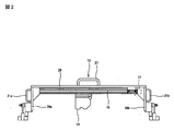
- FIG. 2 is a front view of a wire rope pitch measuring apparatus used when measuring the wire rope pitch by the wire rope pitch measuring method according to the embodiment of the present invention.
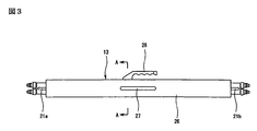
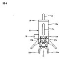
- FIG. 3 is a plan view of the wire rope pitch measuring apparatus shown in FIG. 4 is a left side view of the wire rope pitch measuring apparatus shown in FIG.
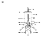
- FIG. 5 is a right side view of the wire rope pitch measuring apparatus shown in FIG.
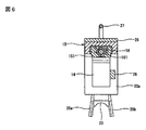
- FIG. 6 is a view showing a cross section taken along the line AA of FIG. FIG.
- FIG. 7 is a block diagram showing an electrical configuration of a wire rope pitch measuring apparatus used when measuring the wire rope pitch by the wire rope pitch measuring method according to one embodiment of the present invention.
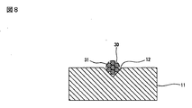
- FIG. 8 is a cross-sectional view showing a state in which the wire rope is housed in the wire rope housing groove formed on the upper surface of the wire rope pitch measuring horizontal base.
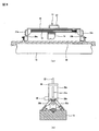
- FIG. 9 is a cross-sectional view showing a state in which the wire rope pitch measuring device is set above the wire rope receiving groove formed on the upper surface of the wire rope pitch measuring horizontal base.
- FIG. 10 is a diagram schematically illustrating laser light emitted to the wire rope from the laser displacement sensor of the wire rope pitch measuring apparatus.
- 11A and 11B are schematic diagrams for explaining the wire rope pitch measurement method and the comparison method according to the present invention.
- FIG. 11A is a plan view of the wire rope viewed from the direction of laser light irradiation
- FIG. 11B is a laser displacement sensor.
- (C) is the top view which looked at the wire rope from the irradiation direction of the laser beam, The graph which shows the relationship between the displacement measured value by A, and the length direction position of a laser displacement sensor.
- 12A is a BB cross section of FIG. 11A
- FIG. 12B is a CC cross section of FIG. 11A
- FIG. 12C is a DD cross section of FIG.
- It is. 13A and 13B are diagrams showing a wire rope pitch measuring method according to another embodiment of the present invention, wherein FIG.
- FIG. 13A is a diagram showing a radial section of the wire rope and a laser displacement sensor
- FIG. 13B is a laser displacement sensor. It is a top view which shows the irradiation position of the laser beam irradiated to the side surface of a wire rope from.
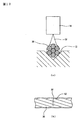
- 14A and 14B are diagrams showing a wire rope pitch measurement method according to another embodiment of the present invention, wherein FIG. 14A is a diagram showing a radial cross section of the wire rope and a laser displacement sensor, and FIG. 14B is a laser displacement sensor. It is a top view which shows the irradiation position of the laser beam irradiated to the side surface of a wire rope from.
- a wire rope pitch measuring method is obtained by using a wire rope pitch measuring horizontal base 11 shown in FIG. 1 and a wire rope pitch measuring device 13 shown in FIGS.
- a wire rope receiving groove 12 is linearly formed on the upper surface of the horizontal base 11 for measuring the wire rope pitch.
- the wire rope accommodating groove 12 accommodates a wire rope that is an object to be measured, and a cross section in the depth direction is formed in a V shape.
- the wire rope pitch measuring device 13 is set above the wire rope receiving groove 12 when measuring the wire rope pitch, and includes a laser displacement sensor 14, a linear guide 15, a ball screw 16, an encoder 17, an arithmetic device 18, and a display. 19, end plates 20a and 20b, positioning members 22a and 22b, a top plate 26 and a slide operation handle 28 are provided.
- the laser displacement sensor 14 is disposed so as to face the side surface of the wire rope accommodated in the wire rope accommodation groove 12, and the distance from the laser displacement sensor 14 to the surface of the wire rope by irradiating the side surface of the wire rope with laser light. Is measured optically.
- the laser light 32 emitted from the laser displacement sensor 14 has a slit shape elongated in the radial direction of the wire rope, receives the laser light reflected along the cross-sectional shape in the radial direction of the wire rope on the surface of the wire rope, and receives the wire.
- the displacement in the irradiation direction of the laser beam on the rope surface is measured over a range of 20 mm, for example (see FIG. 10).
- the linear guide 15 guides the laser displacement sensor 14 in the length direction of the wire rope housed in the wire rope housing groove 12, and the laser displacement sensor 14 is moved to the slider 151 (see FIG. 6) of the linear guide 15. Is installed.
- the ball screw 16 converts the linear motion of the slider 151 into a rotational motion, and has a screw shaft 161 (see FIG. 6) that rotates according to the amount of movement of the slider 151.
- the encoder 17 is a length direction position measuring device that measures the position in the length direction of the laser displacement sensor 14 by detecting the slider movement amount of the linear guide 15, and is connected to the screw shaft 161 of the ball screw 16. Then, the rotation amount of the screw shaft 161 accompanying the slider movement of the slider 151 is detected, and this detected value is converted into a slider movement amount and output as a position in the length direction.
- the computing device 18 computes the pitch of the wire rope based on the signal output from the laser displacement sensor 14 and the signal output from the encoder 17, and is composed of, for example, a microcomputer.
- the display 19 digitally displays the calculation result of the calculation device 18 and is composed of, for example, a liquid crystal display panel.
- the end plates 20a and 20b are provided perpendicular to both ends in the length direction of the linear guide 15 and have setting handles 21a and 21b formed by bending a rod-shaped metal member into a U-shape. These setting handles 21a and 21b are for setting the wire rope pitch measuring device 13 above the wire rope housing groove 12, and are mounted on the outer surfaces of the end plates 20a and 20b.
- the positioning members 22a and 22b are provided on the outer surfaces of the end plates 20a and 20b, and have a concave curved surface 23, horizontal shafts 24a and 24b, and support legs 25a and 25b, respectively.
- the concave curved surface 23 is for positioning the laser displacement sensor 14 and the linear guide 15 above the wire rope housing groove 12, and is curved in an arc shape with respect to the wire rope housed in the wire rope housing groove 12. . Then, by pressing the concave curved surfaces 23 of the pair of positioning members 22a and 22b against the wire rope, the length direction of the wire rope 30 and the guide direction of the linear guide 15 substantially coincide with each other.
- the horizontal shafts 24 a and 24 b support the support legs 25 a and 25 b so as to be freely opened and closed, and project horizontally from the outer surfaces of the positioning members 22 a and 22 b along the wire rope housing grooves 12.
- the support legs 25a and 25b are used to horizontally support the laser displacement sensor 14 and the linear guide 15 above the wire rope housing groove 12, and are pivotally supported around the horizontal axes 24a and 24b. Yes.
- the support legs 25a and 25b are configured so that gears (not shown) provided on the support legs 25a and 25b are engaged with each other and rotated in the reverse direction in conjunction with each other.
- the top plate 26 is formed in a rectangular shape with dimensions of, for example, a width of 63 mm and a length of 685 mm.
- the top plate 26 is fixed to the upper surface of the linear guide 15 and has a carrying handle 27 formed by bending a bar-shaped metal member into a U-shape.
- the carrying handle 27 is for carrying the wire rope pitch measuring device 13 and is attached to the center of the top surface of the top plate 26.
- the slide operation handle 28 is used to slide the laser displacement sensor 14 in the length direction of the wire rope housed in the wire rope housing groove 12, and is attached to the side surface of the laser displacement sensor 14.
- a wire rope 30 formed by twisting a plurality of (for example, six) strands 31 is used as a wire rope. It is accommodated in a wire rope accommodation groove 12 formed on the upper surface of the horizontal base 11 for pitch measurement.
- the wire rope pitch measuring device 13 is set above the wire rope housing groove 12. Specifically, after opening the supporting legs 25a and 25b supported by the horizontal shafts 24a and 24b, the concave curved surface 23 formed on the positioning members 22a and 22b is pressed against the wire rope 30 from above.
- the support legs 25a and 25b are closed, and the tips of the support legs 25a and 25b are brought into contact with the upper surface of the wire rope pitch measuring horizontal base 11 across the wire rope pitch receiving groove 12, so that the linear guide 15 is
- the wire rope pitch measuring device 13 is set above the wire rope housing groove 12 so as to be.
- the laser beam 32 is applied to the wire rope 30 from the laser displacement sensor 14 of the wire rope pitch measuring device 13 as shown in FIG. , And the displacement of the surface of the wire rope 30 is measured by the laser displacement sensor 14. At the same time, the laser displacement sensor 14 is moved in the length direction of the wire rope 30 by operating the slide operation handle 28.
- the laser displacement sensor 14 irradiates the wire rope 30 with a slit-like laser beam 32 that is elongated in the radial direction of the wire rope 30 (direction substantially orthogonal to the length direction).
- the calculation device 18 of the wire rope pitch measurement device 13 calculates the pitch of the wire rope 30 based on the signal output from the laser displacement sensor 14 and the signal output from the encoder 17, and calculates the result. Displayed on the display 19 as the pitch of the wire rope 30.
- FIG. 11 shows the wire rope pitch in the case of using the laser displacement sensor that irradiates slit-shaped laser light according to the embodiment of the present invention and in the case of using the laser displacement sensor that irradiates linear laser light as a comparison method. It is explanatory drawing explaining a measuring method.
- FIG. 11A is a plan view of the wire rope 30 irradiated with the laser light as seen from the laser light irradiation direction, and shows a case where the slide movement direction of the laser displacement sensor coincides with the center line direction of the wire rope. Show. FIG.
- FIG. 11B is a graph showing the relationship between the displacement measurement value by the laser displacement sensor and the slide movement amount (length direction position) of the laser displacement sensor in the case shown in FIG.
- FIG. 11C is a plan view of the wire rope 30 irradiated with laser light as seen from the laser light irradiation direction, and the slide movement direction of the laser displacement sensor is shifted from the center line direction of the wire rope by an angle ⁇ .
- Show the case. 12A, 12B, and 12C show a BB cross-sectional view, a CC cross-sectional view, and a DD cross-sectional view in FIG. 11A, respectively.
- the wire rope 30 is shown by way of example in which six strands 31a, 31b, 31c, 31d, 31e, and 31f are twisted together in a spiral shape.
- the wire rope 30 is irradiated with a slit-like laser beam 32 elongated in the radial direction of the wire rope having a width h in the radial direction of the wire rope.
- the laser displacement sensor 14 is moved to the linear guide 15. Slide in the guide direction.
- the movement locus of the laser beam 32 becomes a hatched movement locus 32a in the drawing.
- the laser displacement sensor 14 uses a point on the wire rope closest to the laser displacement sensor as a measurement point within the range where the slit-shaped laser beam 32 is irradiated.
- the slit-shaped laser light 32 elongated in the radial direction of the wire rope irradiated from the laser displacement sensor 14 to the wire rope 30 is irradiated from the laser displacement sensor 14 so as to be substantially orthogonal to the axial direction of the wire rope 30. Therefore, the laser beam 32 is irradiated on the side surface of the wire rope 30 along the radial cross section of the wire rope 30.
- the laser displacement sensor 14 receives the laser beam 32 reflected along the radial cross section of the wire rope 30.
- the displacement of the side surface of the wire rope 30 is measured using the position on the side surface of the wire rope 30 where the distance between the laser displacement sensor 14 and the side surface of the wire rope 30 is the shortest from the received laser light as a displacement measurement point.
- the distance l b1 between the laser displacement sensor 14 and the point b 1 is the shortest as shown in FIG.
- the irradiation position b 1 at this shortest distance is set as a displacement measurement point.
- the point c 1 from the laser displacement sensor 14 is shown in FIG. Is the shortest distance l c1 , and therefore, c 1 point is set as a displacement measurement point.
- the displacement L of each measurement point is measured while moving the laser displacement sensor 14 in the arrow X direction.
- the displacement L is determined as a reference position at a position away from the laser displacement sensor 14 by a predetermined distance L 0 , and a measured value from L 0 (in the case of FIG. 12A). It is obtained by subtracting l b1 ).
- the measurement point is moved in the width direction of the wire rope.
- the movement trajectory of the point is as indicated by the alternate long and short dash line Y in FIG.
- the measurement point moves in the Y direction, that is, when the measurement point moves as b 1 point ⁇ c 1 point ⁇ d 1 point in FIG. 11A
- the distance between the laser displacement sensor 14 and the wire rope surface also changes. and measuring the displacement value L becomes maximum at a point c.
- FIG. 11B is a graph showing the relationship between the position x in the length direction of the laser displacement sensor and the displacement measurement value L when the slit-shaped laser light 32 is moved in the length direction of the wire rope 30. It is.
- the measurement point is b 1 ⁇ c 1 ⁇ d 1 while measuring the displacement with one strand 31a.
- the curve indicating the relationship between the displacement measurement value L and the position x in the length direction of the laser displacement sensor is a mountain-shaped curve.
- the wire rope pitch P 1 can be calculated by determining the moving distance from the first crest apex c 1 to the seventh crest apex c 7 .
- the arithmetic device 18 records the slide movement amount (length direction position) x of the linear guide 15 output from the encoder 17 and the displacement measurement value L measured by the laser displacement sensor 14 corresponding thereto.
- the highest points c (c 1 , c 2 , c 3 , .., C i ,...) (Hereinafter, the highest point of the chevron is also referred to as pitch measurement point c), and the longitudinal displacement x (x 1 , x 2 , x 3 ,..., X i ,. If the wire rope 30 is 6 strands of wire ropes, by calculating the x i + 6 -x i, obtaining the wire rope pitch P.
- the reason why the laser beam irradiated in this embodiment is the slit-like laser beam 32 will be described with reference to FIGS.
- the laser beam 32 is not slit-like but linear
- the irradiation spot 40 moves along a movement locus Z indicated by a one-dot chain line in FIG.
- a displacement measurement value L is the length direction of the laser displacement sensor
- the pitch measurement points f (f 1 , f 2 ,...) By the linear laser beam are the same as the pitch measurement points c (c 1 , c 2 , c 3 ,...) By the slit laser beam. Therefore, the pitch P 2 obtained by calculating the moving distance from the vertex f 1 of the first mountain to the vertex f 7 of the seventh mountain is the movement from the point c 1 to the point c 7 as described above. the same value as the pitch P 1 calculated in the distance. Therefore, even when a linear laser beam is used as the laser beam to be irradiated, the same pitch measurement result as that obtained when the slit laser beam is used can be obtained.
- FIG. 11C shows a case where the slide movement direction X of the laser displacement sensor 14 and the center line S direction of the wire rope 30 are shifted by a slight angle ⁇ . Since the pitch measurement point c when using the slit laser beam 32 is on the center line S of the wire rope 30 as shown in FIG. 11C, the pitch can be measured correctly.
- FIG. 11C shows a case where the movement locus Z of the irradiation spot intersects with the center line S at the pitch measurement point f 1 .
- the difference between the pitch measurement point c and the pitch measurement point f increases. Therefore, the length direction position x 7 at the pitch measurement point c 7 is different from the length direction position x 7 ′ at the pitch measurement point f 7 . Therefore, the pitch P 1 obtained from the pitch measurement point c obtained by irradiating the slit-shaped laser beam 32 is different from the pitch P 2 obtained from the pitch measurement point f obtained by irradiating the linear laser beam. Value.
- the laser light 32 irradiated by the laser displacement sensor 14 is a laser light having a slit-like cross section.
- the width h in the length direction of the wire rope 30 when the laser beam 32 having a slit-like cross section is irradiated onto the wire rope 30 is slightly bent in the wire rope 30 as the object to be measured.
- the center line of the wire rope 30 is within the irradiation range of the laser beam 32.
- the width h is preferably 1 ⁇ 4 or more of the diameter of the wire rope whose pitch is measured. More preferably, the width h is 1/3 or more of the diameter of the wire rope.
- the reflected light of the laser light generated on the side surface of the wire rope is the diameter of the wire rope 30. It has a length along the direction cross section. That is, reflected light having a length in the circumferential direction of the wire rope is obtained. Further, while measuring the displacement of the side surface of the wire rope along the radial cross section of the wire rope 30, the laser displacement sensor 14 is moved in the length direction of the wire rope 30, and the length direction of the wire rope 30 is measured by the laser displacement sensor 14.
- the position x in the length direction at the pitch measurement point on the center line of the wire rope 30 can be obtained for each strand of the wire rope 30. .
- the pitch P By calculating the pitch P using the longitudinal position x at the pitch measurement point measured for each strand, it is possible to calculate an accurate wire rope pitch. Further, unlike the prior art described above, it is not necessary to bring the two rod-shaped contacts into contact with the wire rope, so that the wire rope pitch can be accurately measured.
- a pair of end plate 20a, 20b is provided in the length direction both ends of the linear guide 15 of the wire rope pitch measuring apparatus 13 set above the wire rope accommodation groove
- a pair of positioning members 22a and 22b having a concave curved surface 23 that is curved in an arc shape with respect to the wire rope 30 are provided on the end plates 20a and 20b.
- the wire rope 30 is accommodated after the wire rope 30 is accommodated in the wire rope accommodating groove 12 formed linearly on the upper surface of the wire rope pitch measuring horizontal base 11. It is not always essential to set the wire rope pitch measuring device 13 above the groove 12. However, by adopting this setting method, it is possible to measure the pitch of the wire rope 30 in a state where the bending of the wire rope 30 is corrected and straightened to some extent. Therefore, in order to further reduce the measurement error due to the bending of the wire rope 30, the wire rope 30 is accommodated in the wire rope accommodating groove 12 formed linearly on the upper surface of the wire rope pitch measuring horizontal base 11, and the wire rope pitch is reduced. It is preferable to measure.
- the wire rope 30 in which each of the positioning members 22a and 22b is housed in the wire rope housing groove 12 is used as a wire rope pitch measuring device set above the wire rope housing groove 12.
- a wire rope 30 having a pair of horizontal shafts 24a and 24b projecting in the length direction and a pair of support legs 25a and 25b rotatably supported around the horizontal shafts 24a and 24b. Measure the pitch.
- the tips of the support legs 25a and 25b can be brought into contact with the upper surface of the wire rope pitch measuring horizontal base 11 across the wire rope pitch receiving groove 12, and the linear guide 15 is supported horizontally above the wire rope 30. Therefore, the pitch of the wire rope 30 can be measured more accurately.
- the device further includes a top plate 26 provided on the upper surface of the linear guide 15. If the plate 26 has a carrying handle 27, the wire rope pitch measuring device can be carried to various measuring locations and the pitch of the wire rope 30 can be measured.
- the encoder 17 connected to the screw shaft 161 of the ball screw 16 is used as a length direction position measuring device.
- any encoder that can detect the amount of slide movement of the slider 151 may be used, and the present invention is not limited to the encoder 17 connected to the screw shaft 161 of the ball screw 16.
- the slider displacement handle 14 is used to move the laser displacement sensor 14 in the length direction of the wire rope 30 when the laser displacement sensor 14 is moved in the length direction of the wire rope 30.
- the ball screw 16 may be driven by an electric motor to move the laser displacement sensor 14 in the length direction of the wire rope 30.
- the wire rope 30 is fixed, and the laser displacement sensor 14 is moved in the length direction of the wire rope 30 by the slider 151, so that the laser displacement sensor 14 is connected to the wire rope 30. It is relatively moved in the length direction of 30.
- the laser displacement sensor 14 may be moved relative to the wire rope 30 in the length direction of the wire rope 30. Good. In this case, instead of measuring the position of the laser displacement sensor 14 in the length direction, the movement amount of the wire rope 30 is measured.
- the laser beam irradiated to the wire rope 30 from the laser displacement sensor 14 is made into the slit-shaped laser beam elongated in the radial direction of the wire rope 30, so that the radial cross section of the wire rope 30 is obtained.
- the side surface of the wire rope is irradiated with laser light, and the position where the distance between the laser displacement sensor 14 and the side surface of the wire rope is the shortest can be set as the measurement point.
- the present invention is not limited to this, and it is only necessary that the position where the distance between the laser displacement sensor 14 and the side surface of the wire rope in the radial cross section is the shortest can be set as the measurement point.
- a plurality of linear laser beams 132 are irradiated on the side surface of the wire rope 30 as shown in FIG. Irradiation may be performed so that the spots 140 are arranged in the radial direction of the wire rope 30.
- the linear laser beam 132 to be irradiated is irradiated. You need to set the number.
- the irradiation position (position of the irradiation spot 240) of the linear laser beam 232 is shown in FIG.
- the position where the distance between the laser displacement sensor 14 and the side surface of the wire rope in the radial cross section of the wire rope 30 is the shortest can be set as the measurement point. In this case, it takes time to scan the linear laser beam 232 in the radial direction of the wire rope 30.
- the speed at which the laser displacement sensor 14 is relatively moved in the length direction of the wire rope 30 is sufficiently smaller than the speed at which the linear laser beam 232 is scanned in the radial direction of the wire rope 30. is there. Note that the scanning with the linear laser beam 232 is possible by irradiating the wire rope 30 with the laser beam from the laser projector via the rotating mirror.
- the wire rope pitch measurement method of the present invention described above is applied to the pitch measurement of the wire rope after twisting a plurality of strands made of a plurality of metal strands into a wire rope, It is possible to accurately determine whether the wire rope pitch is good or defective. That is, based on the measurement result of the wire rope pitch obtained by the wire rope pitch measurement method of the present invention, a wire rope within a predetermined wire rope pitch quality is regarded as a non-defective product, and a wire outside the wire rope pitch quality is determined. If the rope is a defective product, it is possible to accurately determine whether the wire rope pitch is good or defective. Thereby, the pitch quality of the wire rope can be improved.
- the wire rope pitch of the same portion of the wire rope (IWRC6 ⁇ Fi (29) 30 ⁇ ) was measured five times using the method according to the embodiment of the present invention described above.
- the laser displacement sensor 14 for irradiating the slit-shaped laser beam one having a resolution of 0.01 mm and a slit-shaped laser beam width h of 20 mm was used.
- the slide movement range of the laser displacement sensor 14 was 500 mm.
- the wire rope pitch measurement device of the same type as that of the present invention example is measured using a wire rope pitch measuring apparatus of the type in which the two rod-shaped contacts described in Patent Document 1 described above are in contact with the wire rope. was performed five times. Table 1 shows the measurement results of the inventive example and the comparative example.
- the + side error (maximum value ⁇ average value) is 0.16 mm
- the ⁇ side error (average value ⁇ minimum value) is 0.20 mm
- the + side error is 0.6 mm
- the ⁇ side error is 1.1 mm
- the error was larger than that of the example of the present invention.
Landscapes
- Physics & Mathematics (AREA)
- General Physics & Mathematics (AREA)
- Engineering & Computer Science (AREA)
- Computer Vision & Pattern Recognition (AREA)
- Length Measuring Devices By Optical Means (AREA)
Abstract
ワイヤロープのピッチを正確に測定することのできるワイヤロープピッチの測定方法とワイヤロープピッチ測定装置を提供し、さらに、ワイヤロープピッチに関する品質不良の発生を抑制できるワイヤロープの製造方法を提供する。ワイヤロープ30の側面に対向させたレーザ変位センサを用いて、ワイヤロープの径方向断面に沿ってワイヤロープ30の側面にレーザ光32を照射して該側面の変位の計測を行いつつ、レーザ変位センサをワイヤロープ30の長さ方向に相対移動させ、レーザ変位センサのワイヤロープ30に対する前記長さ方向の相対位置と前記変位の計測値との関係から前記ワイヤロープのピッチを算出する。
Description
本発明は、ワイヤロープのピッチを測定する方法と装置、さらには、ワイヤロープの製造方法に関する。
一般に、クレーンなどに使用されるワイヤロープは、多数本の金属素線からなる複数本(通常は3~9本)のストランドを螺旋状に撚り合わせて構成されている。このようなワイヤロープを製品として出荷する際には、ワイヤロープのピッチ(「ストランドピッチ」とも言う。)が予め定められた許容範囲内にあるか否かを検査する必要がある。
そこで、ワイヤロープのピッチを測定する方法として、ワイヤロープピッチ測定装置の長手方向両端部に設けられた二つの挟み部でワイヤロープの二箇所を挟み、この状態でワイヤロープを水平面上に置いた後、挟み部の間に設けられた二つの棒状接触子をワイヤロープに所定の距離(ストランドの本数分)だけ離して上方から押し当て、これら棒状接触子の離間距離を電気的に計測してワイヤロープのピッチを測定する方法が提案されている(例えば、特許文献1参照)。
そこで、ワイヤロープのピッチを測定する方法として、ワイヤロープピッチ測定装置の長手方向両端部に設けられた二つの挟み部でワイヤロープの二箇所を挟み、この状態でワイヤロープを水平面上に置いた後、挟み部の間に設けられた二つの棒状接触子をワイヤロープに所定の距離(ストランドの本数分)だけ離して上方から押し当て、これら棒状接触子の離間距離を電気的に計測してワイヤロープのピッチを測定する方法が提案されている(例えば、特許文献1参照)。
このような方法によると、ワイヤロープのピッチを目視に頼ることなく測定することが可能であるが、ワイヤロープのピッチを正確に測定するためには、二つの棒状接触子をワイヤロープの中心線上に押し当てる必要がある。しかし、ワイヤロープは曲がりやすいため、僅かな曲がりが生じているワイヤロープを二つの挟み部で挟んだ状態でワイヤロープのピッチを測定しようとすると、棒状接触子がワイヤロープの中心線上から外れてしまうことがある。このため、ワイヤロープのピッチを正確に測定することができなくなるという問題点があった。
また、ワイヤロープの製造工程では、ワイヤロープのピッチを正確に測定することができない。このため、ワイヤロープ製品のピッチに関する品質について、正確に検査することができず品質不良品を出荷したり、あるいは、ピッチに関する品質上の許容範囲を、ワイヤロープピッチの測定誤差をも考慮して狭い範囲に設定しておく必要がある等の問題もあった。
本発明は、上述した問題点に着目してなされたもので、ワイヤロープのピッチを正確に測定することのできるワイヤロープピッチの測定方法とワイヤロープピッチ測定装置を提供することを目的とするものである。また、本発明の他の目的は、ワイヤロープの製造工程においてワイヤロープのピッチ測定を正確に行うことで、ワイヤロープのピッチ品質を高めることのできるワイヤロープの製造方法を提供することにある。
本発明は、以下のとおりである。
[1] 金属素線からなる複数本のストランドを螺旋状に撚り合わせてなるワイヤロープのピッチを測定する方法であって、
前記ワイヤロープの側面に対向させたレーザ変位センサを用いて、前記ワイヤロープの径方向断面に沿って前記ワイヤロープの側面にレーザ光を照射して該側面の変位を計測する工程と、
前記ワイヤロープの側面の変位の計測を行いつつ、前記ワイヤロープに対して前記レーザ変位センサを前記ワイヤロープの長さ方向に相対移動させ、前記レーザ変位センサの前記ワイヤロープに対する前記長さ方向の相対位置を計測する工程と、前記長さ方向の相対位置と前記変位の計測値とに基づいて、前記ワイヤロープのピッチを算出する工程を有することを特徴とする。
[1] 金属素線からなる複数本のストランドを螺旋状に撚り合わせてなるワイヤロープのピッチを測定する方法であって、
前記ワイヤロープの側面に対向させたレーザ変位センサを用いて、前記ワイヤロープの径方向断面に沿って前記ワイヤロープの側面にレーザ光を照射して該側面の変位を計測する工程と、
前記ワイヤロープの側面の変位の計測を行いつつ、前記ワイヤロープに対して前記レーザ変位センサを前記ワイヤロープの長さ方向に相対移動させ、前記レーザ変位センサの前記ワイヤロープに対する前記長さ方向の相対位置を計測する工程と、前記長さ方向の相対位置と前記変位の計測値とに基づいて、前記ワイヤロープのピッチを算出する工程を有することを特徴とする。
[2] [1]に記載のワイヤロープピッチの測定方法であって、前記レーザ変位センサは、前記ワイヤロープの径方向に細長いスリット状のレーザ光を照射することを特徴とする。
[3] [1]または[2]に記載のワイヤロープピッチの測定方法であって、前記ワイヤロープをワイヤロープピッチ測定用の水平台の上面に直線状に形成されたワイヤロープ収容溝に収容し、該ワイヤロープ収容溝に収容されたワイヤロープの上方に前記レーザ変位センサを位置させて前記変位の計測および前記相対移動を行うことを特徴とする。
[3] [1]または[2]に記載のワイヤロープピッチの測定方法であって、前記ワイヤロープをワイヤロープピッチ測定用の水平台の上面に直線状に形成されたワイヤロープ収容溝に収容し、該ワイヤロープ収容溝に収容されたワイヤロープの上方に前記レーザ変位センサを位置させて前記変位の計測および前記相対移動を行うことを特徴とする。
[4] 金属素線からなる複数本のストランドを螺旋状に撚り合わせてなるワイヤロープのピッチを測定するワイヤロープピッチ測定装置であって、前記ワイヤロープの側面に対向させてワイヤロープの側面の変位を測定するレーザ変位センサと、該レーザ変位センサを前記ワイヤロープの長さ方向に案内するリニアガイドと、前記レーザ変位センサの前記リニアガイド上の前記長さ方向の位置を測定する長さ方向位置測定器と、前記長さ方向位置測定器からの出力信号と前記レーザ変位センサからの出力信号とに基づいて前記ワイヤロープのピッチを算出する演算装置とを備え、前記レーザ変位センサは、前記ワイヤロープの径方向断面に沿って前記ワイヤロープの側面にレーザ光を照射し、該側面の変位を測定することを特徴とする。
[5] [4]に記載のワイヤロープピッチ測定装置であって、前記レーザ変位センサは、前記ワイヤロープの側面に該ワイヤロープの径方向に細長いスリット状のレーザ光を照射することを特徴とする。
[6] [5]に記載のワイヤロープピッチ測定装置において、前記リニアガイドの長さ方向両端に一対の位置決め部材をさらに有し、該位置決め部材は前記ワイヤロープに押し当てられる凹曲面を有し、該凹曲面が前記ワイヤロープに押し当てられると、前記リニアガイドによる前記レーザ変位センサの案内方向が、前記ワイヤロープの長さ方向となることを特徴とする。
[6] [5]に記載のワイヤロープピッチ測定装置において、前記リニアガイドの長さ方向両端に一対の位置決め部材をさらに有し、該位置決め部材は前記ワイヤロープに押し当てられる凹曲面を有し、該凹曲面が前記ワイヤロープに押し当てられると、前記リニアガイドによる前記レーザ変位センサの案内方向が、前記ワイヤロープの長さ方向となることを特徴とする。
[7] 金属素線からなる複数本のストランドを螺旋状に撚り合わせてワイヤロープとする工程と、
該ワイヤロープの側面に対向させたレーザ変位センサを用いて、前記ワイヤロープの径方向断面に沿って前記ワイヤロープの側面にレーザ光を照射して、該側面の変位を計測する工程と、
前記ワイヤロープの側面の変位の計測を行いつつ、前記ワイヤロープに対して前記レーザ変位センサを前記ワイヤロープの長さ方向に相対移動させ、前記レーザ変位センサの前記ワイヤロープに対する前記長さ方向の相対位置を計測する工程と、
前記長さ方向の相対位置と前記変位の計測値とに基づいて、前記ワイヤロープのピッチを算出してワイヤロープピッチを測定する工程と、
前記ワイヤロープピッチの測定結果が、所定のワイヤロープピッチ品質の範囲内のワイヤロープを良品とし、前記ワイヤロープピッチ品質の範囲外のワイヤロープを不良品とする工程とを有することを特徴とする。
[8] [7]に記載のワイヤロープの製造方法であって、前記レーザ変位センサは、前記ワイヤロープの径方向に細長いスリット状のレーザ光を照射することを特徴とする。
該ワイヤロープの側面に対向させたレーザ変位センサを用いて、前記ワイヤロープの径方向断面に沿って前記ワイヤロープの側面にレーザ光を照射して、該側面の変位を計測する工程と、
前記ワイヤロープの側面の変位の計測を行いつつ、前記ワイヤロープに対して前記レーザ変位センサを前記ワイヤロープの長さ方向に相対移動させ、前記レーザ変位センサの前記ワイヤロープに対する前記長さ方向の相対位置を計測する工程と、
前記長さ方向の相対位置と前記変位の計測値とに基づいて、前記ワイヤロープのピッチを算出してワイヤロープピッチを測定する工程と、
前記ワイヤロープピッチの測定結果が、所定のワイヤロープピッチ品質の範囲内のワイヤロープを良品とし、前記ワイヤロープピッチ品質の範囲外のワイヤロープを不良品とする工程とを有することを特徴とする。
[8] [7]に記載のワイヤロープの製造方法であって、前記レーザ変位センサは、前記ワイヤロープの径方向に細長いスリット状のレーザ光を照射することを特徴とする。
本発明のワイヤロープピッチの測定方法とワイヤロープピッチ測定装置によると、ワイヤロープに曲がりがあってもレーザ光の照射領域がワイヤロープの中心線上から外れることがなく、しかも二本の棒状接触子をワイヤロープに接触させる必要もないので、ワイヤロープのピッチを正確に測定することができる。また、本発明のワイヤロープの製造方法によると、ワイヤロープピッチに関する品質が良好なワイヤロープを製造できる。
以下、図1~図14を参照して本発明の実施の形態について説明する。
本発明の一実施形態に係るワイヤロープピッチの測定方法は、図1に示すワイヤロープピッチ測定用水平台11と図2~図7に示すワイヤロープピッチ測定装置13とを用いてワイヤロープのピッチを測定する方法であって、ワイヤロープピッチ測定用水平台11の上面にはワイヤロープ収容溝12が直線状に形成されている。ワイヤロープ収容溝12は測定対象物であるワイヤロープを収容するものであって、深さ方向の断面がV字形状に形成されている。
本発明の一実施形態に係るワイヤロープピッチの測定方法は、図1に示すワイヤロープピッチ測定用水平台11と図2~図7に示すワイヤロープピッチ測定装置13とを用いてワイヤロープのピッチを測定する方法であって、ワイヤロープピッチ測定用水平台11の上面にはワイヤロープ収容溝12が直線状に形成されている。ワイヤロープ収容溝12は測定対象物であるワイヤロープを収容するものであって、深さ方向の断面がV字形状に形成されている。
ワイヤロープピッチ測定装置13は、ワイヤロープのピッチを測定するときにワイヤロープ収容溝12の上方にセットされ、レーザ変位センサ14、リニアガイド15、ボールねじ16、エンコーダ17、演算装置18、表示器19、端板20a,20b、位置決め部材22a,22b、天板26およびスライド操作用取っ手28を備えている。
レーザ変位センサ14は、ワイヤロープ収容溝12に収容されたワイヤロープの側面に対向させて配置して、レーザ光をワイヤロープの側面に照射してレーザ変位センサ14からワイヤロープの表面までの距離を光学的に計測するものである。レーザ変位センサ14から照射されるレーザ光32は、ワイヤロープの径方向に細長いスリット状であり、ワイヤロープの表面でワイヤロープの径方向の断面形状に沿って反射したレーザ光を受光してワイヤロープ表面のレーザ光の照射方向の変位を例えば20mmの範囲にわたって計測するように構成されている(図10参照)。
リニアガイド15は、ワイヤロープ収容溝12に収容されたワイヤロープの長さ方向にレーザ変位センサ14を案内するものであって、このリニアガイド15のスライダ151(図6参照)にレーザ変位センサ14が装着されている。
ボールねじ16は、スライダ151の直線運動を回転運動に変換するものであって、スライダ151の移動量に応じて回転するねじ軸161(図6参照)を有している。
ボールねじ16は、スライダ151の直線運動を回転運動に変換するものであって、スライダ151の移動量に応じて回転するねじ軸161(図6参照)を有している。
エンコーダ17は、リニアガイド15のスライダ移動量を検出することで、レーザ変位センサ14の長さ方向位置を測定する長さ方向位置測定器であって、ボールねじ16のねじ軸161に連結されており、スライダ151のスライダ移動に伴うねじ軸161の回転量を検出し、この検出値をスライダ移動量に変換して長さ方向位置として出力する。
演算装置18は、レーザ変位センサ14から出力された信号とエンコーダ17から出力された信号とに基づいてワイヤロープのピッチを演算するものであって、例えばマイクロコンピュータなどから構成されている。
演算装置18は、レーザ変位センサ14から出力された信号とエンコーダ17から出力された信号とに基づいてワイヤロープのピッチを演算するものであって、例えばマイクロコンピュータなどから構成されている。
表示器19は、演算装置18の演算結果をデジタル表示するものであって、例えば液晶表示パネルなどから構成されている。
端板20a,20bは、リニアガイド15の長さ方向両端側に垂直に設けられ、棒状の金属部材をコ字状に曲げ加工してなるセット用取っ手21a,21bを有している。これらのセット用取っ手21a,21bは、ワイヤロープピッチ測定装置13をワイヤロープ収容溝12の上方にセットするためのもので、端板20a,20bの外面に装着されている。
位置決め部材22a,22bは端板20a,20bの外面に設けられ、凹曲面23、水平軸24a,24b及び支持脚25a,25bをそれぞれ有している。
端板20a,20bは、リニアガイド15の長さ方向両端側に垂直に設けられ、棒状の金属部材をコ字状に曲げ加工してなるセット用取っ手21a,21bを有している。これらのセット用取っ手21a,21bは、ワイヤロープピッチ測定装置13をワイヤロープ収容溝12の上方にセットするためのもので、端板20a,20bの外面に装着されている。
位置決め部材22a,22bは端板20a,20bの外面に設けられ、凹曲面23、水平軸24a,24b及び支持脚25a,25bをそれぞれ有している。
凹曲面23は、ワイヤロープ収容溝12の上方にレーザ変位センサ14やリニアガイド15を位置させるためのもので、ワイヤロープ収容溝12に収容されたワイヤロープに対して円弧状に湾曲している。そして、一対の位置決め部材22a,22bのそれぞれの凹曲面23をワイヤロープに押し当てることで、ワイヤロープ30の長さ方向とリニアガイド15の案内方向とが概ね一致するようになっている。
水平軸24a,24bは、支持脚25a,25bを開閉自在に支持するものであって、ワイヤロープ収容溝12に沿って位置決め部材22a,22bの外面から水平に突出している。
支持脚25a,25bは、レーザ変位センサ14やリニアガイド15をワイヤロープ収容溝12の上方に水平に支持するためのもので、水平軸24a,24bの軸回りに回動自在に軸支されている。支持脚25a,25bは、それぞれに設けた歯車(図示せず)が噛み合わされて、連動して逆方向に回動するように構成されている。
支持脚25a,25bは、レーザ変位センサ14やリニアガイド15をワイヤロープ収容溝12の上方に水平に支持するためのもので、水平軸24a,24bの軸回りに回動自在に軸支されている。支持脚25a,25bは、それぞれに設けた歯車(図示せず)が噛み合わされて、連動して逆方向に回動するように構成されている。
天板26は、例えば幅63mm、長さ685mmの寸法で長方形状に形成されている。また、天板26はリニアガイド15の上面に固設され、棒状の金属部材をコ字状に曲げ加工してなる持ち運び用取っ手27を有している。この持ち運び用取っ手27はワイヤロープピッチ測定装置13を持ち運ぶためのもので、天板26の上面中央部に装着されている。
スライド操作用取っ手28は、ワイヤロープ収容溝12に収容されたワイヤロープの長さ方向にレーザ変位センサ14をスライド操作するためのものであって、レーザ変位センサ14の側面に装着されている。
スライド操作用取っ手28は、ワイヤロープ収容溝12に収容されたワイヤロープの長さ方向にレーザ変位センサ14をスライド操作するためのものであって、レーザ変位センサ14の側面に装着されている。
このようなワイヤロープピッチ測定装置13を用いてワイヤロープのピッチを測定する場合は、図8に示すように、複数本(例えば6本)のストランド31を撚り合わせてなるワイヤロープ30をワイヤロープピッチ測定用水平台11の上面に形成されたワイヤロープ収容溝12に収容する。次に、図9に示すように、ワイヤロープ収容溝12の上方にワイヤロープピッチ測定装置13をセットする。具体的には、水平軸24a,24bに軸支された支持脚25a,25bを開いた後、位置決め部材22a,22bに形成された凹曲面23をワイヤロープ30に上方から押し当てる。そして、この状態で支持脚25a,25bを閉じ、支持脚25a,25bの先端部をワイヤロープピッチ測定用水平台11の上面にワイヤロープピッチ収容溝12を跨いで接触させ、リニアガイド15が水平となるようにワイヤロープピッチ測定装置13をワイヤロープ収容溝12の上方にセットする。
このようにしてワイヤロープ収容溝12の上方にワイヤロープピッチ測定装置13をセットしたならば、図10に示すように、ワイヤロープピッチ測定装置13のレーザ変位センサ14からワイヤロープ30にレーザ光32を照射し、ワイヤロープ30の表面の変位をレーザ変位センサ14によって計測する。また、これと同時に、スライド操作用取っ手28を操作してレーザ変位センサ14をワイヤロープ30の長さ方向に移動させる。
このとき、レーザ変位センサ14からは、図10に示すように、ワイヤロープ30の径方向(長さ方向とは概ね直交する方向)に細長いスリット状のレーザ光32がワイヤロープ30に照射される。また、このとき、ワイヤロープピッチ測定装置13の演算装置18では、レーザ変位センサ14から出力された信号とエンコーダ17から出力された信号とに基づいてワイヤロープ30のピッチを演算し、その結果を表示器19にワイヤロープ30のピッチとして表示する。
演算装置18による、ワイヤロープピッチの演算法を図11、図12を参照して説明する。なお、レーザ光32がスリット状でない場合についても比較として説明する。
図11は、本発明の実施形態に係るスリット状のレーザ光を照射するレーザ変位センサを用いる場合と、比較法として直線状のレーザ光を照射するレーザ変位センサを用いる場合における、ワイヤロープピッチの測定法を説明する説明図である。図11(a)は、レーザ光を照射したワイヤロープ30をレーザ光の照射方向から見た平面図であり、レーザ変位センサのスライド移動方向がワイヤロープの中心線方向と一致している場合を示す。図11(b)は、図11(a)に示す場合においてレーザ変位センサによる変位測定値とレーザ変位センサのスライド移動量(長さ方向位置)との関係を示すグラフである。図11(c)は、レーザ光を照射したワイヤロープ30をレーザ光の照射方向から見た平面図であり、レーザ変位センサのスライド移動方向がワイヤロープの中心線方向から角度θだけずれている場合を示す。図12(a),(b),(c)は、それぞれ、図11(a)におけるB−B断面図、C−C断面図、D−D断面図を示す。
なお、図11、図12においては、ワイヤロープ30が、6本のストランド31a,31b,31c,31d,31e,31fを螺旋状に撚り合わせた場合を例にとって示してある。
図11は、本発明の実施形態に係るスリット状のレーザ光を照射するレーザ変位センサを用いる場合と、比較法として直線状のレーザ光を照射するレーザ変位センサを用いる場合における、ワイヤロープピッチの測定法を説明する説明図である。図11(a)は、レーザ光を照射したワイヤロープ30をレーザ光の照射方向から見た平面図であり、レーザ変位センサのスライド移動方向がワイヤロープの中心線方向と一致している場合を示す。図11(b)は、図11(a)に示す場合においてレーザ変位センサによる変位測定値とレーザ変位センサのスライド移動量(長さ方向位置)との関係を示すグラフである。図11(c)は、レーザ光を照射したワイヤロープ30をレーザ光の照射方向から見た平面図であり、レーザ変位センサのスライド移動方向がワイヤロープの中心線方向から角度θだけずれている場合を示す。図12(a),(b),(c)は、それぞれ、図11(a)におけるB−B断面図、C−C断面図、D−D断面図を示す。
なお、図11、図12においては、ワイヤロープ30が、6本のストランド31a,31b,31c,31d,31e,31fを螺旋状に撚り合わせた場合を例にとって示してある。
図11に示すように、ワイヤロープの径方向に幅hを有するワイヤロープの径方向に細長いスリット状のレーザ光32をワイヤロープ30に照射し、この状態でレーザ変位センサ14をリニアガイド15の案内方向にスライド移動させる。このとき、ワイヤロープ30の表面に照射されたレーザ光32は矢印X方向に移動するので、レーザ光32の移動軌跡は図中ハッチングを施した移動軌跡32aとなる。レーザ変位センサ14は、スリット状のレーザ光32が照射されている範囲内で最もレーザ変位センサと近いワイヤロープ上の点を測定点とする。
レーザ変位センサ14からワイヤロープ30に照射されるワイヤロープの径方向に細長いスリット状のレーザ光32は、レーザ変位センサ14からワイヤロープ30の軸方向に略直交するように照射される。したがって、ワイヤロープ30の径方向断面に沿ったワイヤロープ30の側面にレーザ光32は照射される。レーザ変位センサ14はワイヤロープ30の径方向断面に沿って反射されたレーザ光32を受光する。
受光したレーザ光からレーザ変位センサ14とワイヤロープ30の側面との距離が最短である、ワイヤロープ30の側面上の位置を変位測定点としてワイヤロープ30の側面の変位計測を行う。例えば、図11中のB−B線上にスリット状のレーザ光32が照射されている場合は、図12(a)に示すように、レーザ変位センサ14とb1点までの距離lb1が最短距離となり、この最短距離での照射位置b1を変位の測定点とする。レーザ変位センサ14を矢印X方向に移動させて図11中のC−C線上にレーザ光32が照射されている場合は、図12(b)に示すようにレーザ変位センサ14からはc1点までの距離lc1が最短となり、よってc1点を変位の測定点とする。さらに、レーザ変位センサ14を矢印X方向に移動させて図11中のD−D線上にレーザ光32が照射されている場合は、レーザ変位センサ14からはd1点までの距離ld1が最短となり、よってd1点を変位の測定点とする。このように、レーザ変位センサ14を矢印X方向に移動させつつ各測定点の変位Lを計測する。
変位Lは、例えば図12(a)に示すように、レーザ変位センサ14から所定距離L0だけ離れた位置を基準位置として定めておき、L0から測定値(図12(a)の場合はlb1)を減ずることで求める。このように、レーザ変位センサ14をワイヤロープ30の長さ方向に移動させていくに従って、測定点がワイヤロープの幅方向に移動していくので、スリット状のレーザ光32で測定した場合の測定点の移動軌跡は、図11(a)中の一点鎖線Yに示すようになる。測定点がY方向へ移動、すなわち、測定点が図11(a)中のb1点→c1点→d1点のように移動すると、レーザ変位センサ14とワイヤロープ表面との距離も変化し、変位計測値Lはc1点で最も大きくなる。
図11(b)の上段は、スリット状のレーザ光32をワイヤロープ30の長さ方向に移動させたときの、レーザ変位センサの長さ方向位置xと変位計測値Lとの関係を示すグラフである。図11(a)と図11(b)の上段のグラフとを比較してわかるように、1つのストランド31aで変位を計測している間に、測定点がb1→c1→d1のように変化し、これに伴い変位計測値Lとレーザ変位センサの長さ方向位置xとの関係を示す曲線は山形の曲線となる。測定点がストランド31a,31b,31d,…と移る毎にそれぞれ山形の曲線を示す。例えば6ストランドのワイヤの場合、1つ目の山の頂点c1から7つ目の山の頂点c7までの移動距離を求めることでワイヤロープのピッチP1を算出できる。
レーザ変位センサ14からワイヤロープ30に照射されるワイヤロープの径方向に細長いスリット状のレーザ光32は、レーザ変位センサ14からワイヤロープ30の軸方向に略直交するように照射される。したがって、ワイヤロープ30の径方向断面に沿ったワイヤロープ30の側面にレーザ光32は照射される。レーザ変位センサ14はワイヤロープ30の径方向断面に沿って反射されたレーザ光32を受光する。
受光したレーザ光からレーザ変位センサ14とワイヤロープ30の側面との距離が最短である、ワイヤロープ30の側面上の位置を変位測定点としてワイヤロープ30の側面の変位計測を行う。例えば、図11中のB−B線上にスリット状のレーザ光32が照射されている場合は、図12(a)に示すように、レーザ変位センサ14とb1点までの距離lb1が最短距離となり、この最短距離での照射位置b1を変位の測定点とする。レーザ変位センサ14を矢印X方向に移動させて図11中のC−C線上にレーザ光32が照射されている場合は、図12(b)に示すようにレーザ変位センサ14からはc1点までの距離lc1が最短となり、よってc1点を変位の測定点とする。さらに、レーザ変位センサ14を矢印X方向に移動させて図11中のD−D線上にレーザ光32が照射されている場合は、レーザ変位センサ14からはd1点までの距離ld1が最短となり、よってd1点を変位の測定点とする。このように、レーザ変位センサ14を矢印X方向に移動させつつ各測定点の変位Lを計測する。
変位Lは、例えば図12(a)に示すように、レーザ変位センサ14から所定距離L0だけ離れた位置を基準位置として定めておき、L0から測定値(図12(a)の場合はlb1)を減ずることで求める。このように、レーザ変位センサ14をワイヤロープ30の長さ方向に移動させていくに従って、測定点がワイヤロープの幅方向に移動していくので、スリット状のレーザ光32で測定した場合の測定点の移動軌跡は、図11(a)中の一点鎖線Yに示すようになる。測定点がY方向へ移動、すなわち、測定点が図11(a)中のb1点→c1点→d1点のように移動すると、レーザ変位センサ14とワイヤロープ表面との距離も変化し、変位計測値Lはc1点で最も大きくなる。
図11(b)の上段は、スリット状のレーザ光32をワイヤロープ30の長さ方向に移動させたときの、レーザ変位センサの長さ方向位置xと変位計測値Lとの関係を示すグラフである。図11(a)と図11(b)の上段のグラフとを比較してわかるように、1つのストランド31aで変位を計測している間に、測定点がb1→c1→d1のように変化し、これに伴い変位計測値Lとレーザ変位センサの長さ方向位置xとの関係を示す曲線は山形の曲線となる。測定点がストランド31a,31b,31d,…と移る毎にそれぞれ山形の曲線を示す。例えば6ストランドのワイヤの場合、1つ目の山の頂点c1から7つ目の山の頂点c7までの移動距離を求めることでワイヤロープのピッチP1を算出できる。
演算装置18は、エンコーダ17から出力されたリニアガイド15のスライド移動量(長さ方向位置)xと、それに対応したレーザ変位センサ14により計測した変位計測値Lとを記録する。次に、図11(b)の上段に示すようなスライド移動量(長さ方向位置)xと変位計測位置Lの曲線とから、それぞれ山形について最高点c(c1,c2,c3,…,ci,…)(以下、山形の最高点をピッチ測定点cとも言う。)における長さ方向変位x(x1,x2,x3,…,xi,…)を求め、例えばワイヤロープ30が6ストランドのワイヤロープである場合には、xi+6−xiを算出することで、ワイヤロープピッチPを求める。
次に、本実施形態において照射するレーザ光を、スリット状のレーザ光32とする理由について、図11、図12を用いて説明する。
レーザ光32がスリット状でなく直線状である場合には、レーザ変位センサをワイヤロープの長さ方向に移動させた時、図11(a)に示すようにレーザ光の照射スポット40がX方向に移動する。そのため、照射スポット40は、図11(a)中に一点鎖線で示す移動軌跡Zに沿って移動する。照射スポット40がストランド31aの表面を移動するとき、ワイヤロープ30の表面上のe点→f1点→g点のように移動していくので、レーザ変位センサによる変位計測値Lは長さ方向位置xの変化に伴い図11(b)の下段に示すように変化する。
図11(b)の下段に示すようなスライド移動量(長さ方向位置)xと変位計測値Lとの関係を示す曲線から、それぞれの山形について最高点f(f1,f2,f3,…,fi,…)(以下、山形の最高点をピッチ測定点fとも言う。)における長さ方向位置x(x1,x2,x3,…,xi,…)を求め、例えばワイヤロープ30が6ストランドのワイヤロープである場合には、xi+6−xiを算出することで、ワイヤロープピッチPを求めることができる。
図11(a)は、レーザ変位センサ14のスライド移動方向Xとワイヤロープ30の中心線方向Sとが完全に一致している場合を示している。したがって、直線状のレーザ光によるピッチ測定点f(f1,f2,…)は、スリット状のレーザ光によるピッチ測定点c(c1,c2,c3,…)と同一となる。そのため、1つ目の山の頂点f1から7つ目の山の頂点f7までの移動距離を求めることで得られるピッチP2は、上述のようにc1点からc7点までの移動距離で求めたピッチP1と同一の値となる。したがって、照射するレーザ光として直線状のレーザ光を用いた場合にも、スリット状のレーザ光を用いた場合と同様のピッチ測定結果を得ることができる。
レーザ光32がスリット状でなく直線状である場合には、レーザ変位センサをワイヤロープの長さ方向に移動させた時、図11(a)に示すようにレーザ光の照射スポット40がX方向に移動する。そのため、照射スポット40は、図11(a)中に一点鎖線で示す移動軌跡Zに沿って移動する。照射スポット40がストランド31aの表面を移動するとき、ワイヤロープ30の表面上のe点→f1点→g点のように移動していくので、レーザ変位センサによる変位計測値Lは長さ方向位置xの変化に伴い図11(b)の下段に示すように変化する。
図11(b)の下段に示すようなスライド移動量(長さ方向位置)xと変位計測値Lとの関係を示す曲線から、それぞれの山形について最高点f(f1,f2,f3,…,fi,…)(以下、山形の最高点をピッチ測定点fとも言う。)における長さ方向位置x(x1,x2,x3,…,xi,…)を求め、例えばワイヤロープ30が6ストランドのワイヤロープである場合には、xi+6−xiを算出することで、ワイヤロープピッチPを求めることができる。
図11(a)は、レーザ変位センサ14のスライド移動方向Xとワイヤロープ30の中心線方向Sとが完全に一致している場合を示している。したがって、直線状のレーザ光によるピッチ測定点f(f1,f2,…)は、スリット状のレーザ光によるピッチ測定点c(c1,c2,c3,…)と同一となる。そのため、1つ目の山の頂点f1から7つ目の山の頂点f7までの移動距離を求めることで得られるピッチP2は、上述のようにc1点からc7点までの移動距離で求めたピッチP1と同一の値となる。したがって、照射するレーザ光として直線状のレーザ光を用いた場合にも、スリット状のレーザ光を用いた場合と同様のピッチ測定結果を得ることができる。
しかしながら、実際のワイヤロープにはわずかな曲がりがあるため、レーザ変位センサ14のスライド移動方向Xとワイヤロープ30の中心線S方向とを完全に一致させることは困難である。図11(c)は、レーザ変位センサ14のスライド移動方向Xとワイヤロープ30の中心線S方向とがわずかな角度θだけずれている場合を示している。スリット状のレーザ光32を用いた場合のピッチ測定点cは図11(c)に示すようにワイヤロープ30の中心線S上となるので、正しくピッチを測定することができる。
一方、直線状のレーザ光を用いた場合には、照射スポットの移動軌跡Zはワイヤロープ30の中心線Sとは一致しない。図11(c)は、ピッチ測定点f1で照射スポットの移動軌跡Zが中心線Sと交差している場合を示す。照射スポットの移動軌跡Zが中心線Sから離れるにつれて、ピッチ測定点cとピッチ測定点fとのずれが大きくなる。したがって、ピッチ測定点c7における長さ方向位置x7とピッチ測定点f7における長さ方向位置x7’とは異なる。よって、スリット状のレーザ光32を照射して得たピッチ測定点cから求められるピッチP1と、直線状のレーザ光を照射して得たピッチ測定点fから求められるピッチP2とは異なる値となる。
このように、直線状のレーザ光を照射して得たピッチ測定点fを得る場合、レーザ変位センサのスライド方向がワイヤロープの中心線Sの方向からわずかにずれてしまった場合には、ピッチを正しく測定することができず、測定誤差が大きくなってしまう。前述した先行技術のように、二本の棒状接触子をワイヤロープに接触させてピッチを測定する場合も、二本の棒状接触子の接触位置を中心線S上に正確に合わせることは困難であり、測定誤差は、同様に大きくなる。
以上のことから、本実施形態では、レーザ変位センサ14が照射するレーザ光32はスリット状の断面を有するレーザ光としている。ここで、スリット状の断面を有するレーザ光32がワイヤロープ30上に照射されたときの、ワイヤロープ30の長さ方向の幅hは、被測定物であるワイヤロープ30に多少曲がりがあってもレーザ光32の照射範囲内にワイヤロープ30の中心線が入る程度の大きさがあればよい。具体的には、上記の幅hは、ピッチを測定するワイヤロープの径の1/4以上であることが好ましい。さらに好ましくは、上記の幅hは、ワイヤロープの径の1/3以上である。
なお、レーザ変位センサ14のスライド方向がワイヤロープ30の中心線Sと角度θだけずれている場合、正しいピッチをP0とするとピッチ測定点cに基づいて求まるピッチP1の値はP0・cosθとなる。しかし、目視でこのずれ角θが生じていない程度にセッティングを行えば、θは0に近い値とすることができ、測定誤差P0−P1の大きさは無視できる程度である。
このように、ワイヤロープ30の径方向に細長いスリット状のレーザ光32をレーザ変位センサ14からワイヤロープ30に照射することにより、ワイヤロープ側面に生ずるレーザ光の反射光は、ワイヤロープ30の径方向断面に沿った長さを有するものとなる。つまり、ワイヤロープの周方向に長さを有する反射光が得られる。
また、ワイヤロープ30の径方向断面に沿ったワイヤロープ側面の変位を測定しつつ、レーザ変位センサ14をワイヤロープ30の長さ方向に移動させ、レーザ変位センサ14でワイヤロープ30の長さ方向の位置毎の距離を計測することにより、ワイヤロープ30に曲がりがあっても、ワイヤロープ30のストランド毎にワイヤロープ30の中心線上にあるピッチ測定点における長さ方向位置xを求めることができる。このストランド毎に計測されたピッチ測定点における長さ方向位置xを用いてピッチPを算出することにより、正確なワイヤロープピッチを算出することが可能となる。また、前述した先行技術のように、二本の棒状接触子をワイヤロープに接触させる必要もないので、ワイヤロープピッチを正確に測定することができる。
また、ワイヤロープ30の径方向断面に沿ったワイヤロープ側面の変位を測定しつつ、レーザ変位センサ14をワイヤロープ30の長さ方向に移動させ、レーザ変位センサ14でワイヤロープ30の長さ方向の位置毎の距離を計測することにより、ワイヤロープ30に曲がりがあっても、ワイヤロープ30のストランド毎にワイヤロープ30の中心線上にあるピッチ測定点における長さ方向位置xを求めることができる。このストランド毎に計測されたピッチ測定点における長さ方向位置xを用いてピッチPを算出することにより、正確なワイヤロープピッチを算出することが可能となる。また、前述した先行技術のように、二本の棒状接触子をワイヤロープに接触させる必要もないので、ワイヤロープピッチを正確に測定することができる。
また、上述した本発明の一実施形態では、ワイヤロープ収容溝12の上方にセットされるワイヤロープピッチ測定装置13のリニアガイド15の長さ方向両端側に一対の端板20a,20bを設け、さらに端板20a,20bに、ワイヤロープ30に対して円弧状に湾曲する凹曲面23を有する一対の位置決め部材22a,22bを設けている。この凹曲面23をワイヤロープ30に上方から押し当てて、ワイヤロープ30に対してワイヤロープピッチ測定装置13をセットすることにより、レーザ変位センサ14のスライド移動方向Xとワイヤロープ30の中心線とが大きくずれることを防止できる。したがって、この位置決め部材22a,22bの間にあるワイヤロープ30に曲がりが生じていたとしても、上述したように、ワイヤロープ30の中心線とレーザ変位センサ14のスライド移動方向Xとがわずかにずれていても、その測定誤差は小さい。
ここで、上述した本発明の一実施形態に示したように、ワイヤロープピッチ測定用水平台11の上面に直線状に形成されたワイヤロープ収容溝12にワイヤロープ30を収容した後、ワイヤロープ収容溝12の上方にワイヤロープピッチ測定装置13をセットすることは必ずしも必須ではない。しかし、このセット方法を採用することにより、ワイヤロープ30の曲がりが矯正されて、ある程度真っ直ぐにされた状態でワイヤロープ30のピッチを測定することができる。したがって、ワイヤロープ30の曲がりによる測定誤差をさらに小さくするために、ワイヤロープピッチ測定用水平台11の上面に直線状に形成されたワイヤロープ収容溝12にワイヤロープ30を収容してワイヤロープピッチを測定することが好ましい。
さらに、上述した本発明の一実施形態では、ワイヤロープ収容溝12の上方にセットされるワイヤロープピッチ測定装置として、位置決め部材22a,22bの各々がワイヤロープ収容溝12に収容されたワイヤロープ30の長さ方向に突出する一対の水平軸24a,24bと、水平軸24a,24bの軸回りに回動自在に軸支された一対の支持脚25a,25bとを有するものを用いてワイヤロープ30のピッチを測定する。これにより、支持脚25a,25bの先端部をワイヤロープピッチ測定用水平台11の上面にワイヤロープピッチ収容溝12を跨いで接触させることができ、ワイヤロープ30の上方にリニアガイド15が水平に支持されるため、ワイヤロープ30のピッチをより正確に測定することができる。
また、ワイヤロープ収容溝12の上方にセットされるワイヤロープピッチ測定装置として、上述した本発明の一実施形態のように、リニアガイド15の上面に設けられた天板26をさらに備え、かつ天板26が持ち運び用取っ手27を有するものとすれば、ワイヤロープピッチ測定装置を様々な測定場所に持ち運んでワイヤロープ30のピッチを測定することができる。
上述した本発明の一実施形態では、長さ方向位置測定器としてボールねじ16のねじ軸161に連結されたエンコーダ17を用いている。しかし、スライダ151のスライド移動量を検出できるものであれば良く、ボールねじ16のねじ軸161に連結されたエンコーダ17に限定されるものではない。
上述した本発明の一実施形態では、長さ方向位置測定器としてボールねじ16のねじ軸161に連結されたエンコーダ17を用いている。しかし、スライダ151のスライド移動量を検出できるものであれば良く、ボールねじ16のねじ軸161に連結されたエンコーダ17に限定されるものではない。
また、上述した本発明の一実施形態では、レーザ変位センサ14をワイヤロープ30の長さ方向に移動させるときにスライダ操作用取っ手28を利用してレーザ変位センサ14をワイヤロープ30の長さ方向に移動させるようにした。しかし、例えばボールねじ16を電動モータにて駆動してレーザ変位センサ14をワイヤロープ30の長さ方向に移動させてもよい。
また、上述した一実施形態では、ワイヤロープ30を固定し、レーザ変位センサ14をスライダ151によりワイヤロープ30の長さ方向に移動させることで、ワイヤロープ30に対してレーザ変位センサ14をワイヤロープ30の長さ方向に相対移動させている。しかし、レーザ変位センサ14を固定し、ワイヤロープ30をその長さ方向に移動させることで、ワイヤロープ30に対してレーザ変位センサ14をワイヤロープ30の長さ方向に相対移動させるようにしてもよい。この場合、レーザ変位センサ14の長さ方向の位置を測定することに代えて、ワイヤロープ30の移動量を測定する。
また、上述した一実施形態では、レーザ変位センサ14からワイヤロープ30に照射するレーザ光を、ワイヤロープ30の径方向に細長いスリット状のレーザ光とすることにより、ワイヤロープ30の径方向断面に沿ったワイヤロープ側面にレーザ光を照射し、レーザ変位センサ14とワイヤロープ側面との距離が最短である位置を測定点とすることを可能としている。しかし、本発明は、これに限定されず、上記径方向断面におけるレーザ変位センサ14とワイヤロープ側面との距離が最短である位置を測定点とすることが可能であればよい。
例えば、図10に示したように、スリット状のレーザ光32を照射することに代えて、図13に示すように、複数の直線状のレーザ光132を、そのワイヤロープ30の側面上の照射スポット140がワイヤロープ30の径方向に配列するように照射してもよい。この場合、隣り合う照射スポット140の間隔が大きいと、ワイヤロープ30の側面との距離が最短である位置を測定点でなくなるので、測定精度を考慮して、照射する直線状のレーザ光132の数を設定する必要がある。
また、図10に示したように、スリット状のレーザ光32を照射することに代えて、図14に示すように、直線状のレーザ光232の照射位置(照射スポット240の位置)を、図中の矢印に示すように、ワイヤロープ30の径方向に走査しても良い。これによっても、ワイヤロープ30の径方向断面におけるレーザ変位センサ14とワイヤロープ側面との距離が最短である位置を測定点とすることが可能である。この場合、直線状のレーザ光232をワイヤロープ30の径方向に走査するには時間がかかる。したがって、レーザ変位センサ14をワイヤロープ30の長さ方向に相対移動させる速度は、直線状のレーザ光232をワイヤロープ30の径方向に走査する速度に比べて十分に小さくするという配慮が必要である。なお、直線状レーザ光232の走査は、レーザ投光器からのレーザ光を、回転ミラーを介して、ワイヤロープ30に照射することで可能である。
このように、スリット状のレーザ光32に代えて、直線状のレーザ光をワイヤロープ30に照射する場合は、複数の直線状のレーザ光132をワイヤロープ30の径方向に配列させて照射する必要がある。したがって、測定精度を確保する上では多数のレーザ光の照射を必要とする。また、直線状のレーザ光232をワイヤロープ30の径方向に走査する場合には、レーザ変位センサ14をワイヤロープ30の長さ方向に相対移動させる速度を遅くするという配慮を必要とする。したがって、スリット状のレーザ光を照射することが最も好ましい。
以上説明した、本発明のワイヤロープピッチ測定方法を、多数本の金属素線からなる複数本のストランドを螺旋状に撚り合わせてワイヤロープとなした後のワイヤロープのピッチ測定に適用すれば、ワイヤロープピッチに関する良品、不良品の判定を正確に行うことができる。すなわち、本発明のワイヤロープピッチ測定方法により得られたワイヤロープピッチの測定結果に基づいて、所定のワイヤロープピッチ品質の範囲内のワイヤロープを良品とし、該ワイヤロープピッチ品質の範囲外のワイヤロープを不良品とすれば、ワイヤロープピッチに関する良品、不良品の判定を正確に行うことができる。これにより、ワイヤロープのピッチ品質を向上させることも可能となる。
本発明例として、上述した本発明の一実施形態による方法を用いてワイヤロープ(IWRC6×Fi(29)30φ)の同一部分のワイヤロープピッチの測定を5回行った。ここで、スリット状のレーザ光を照射するレーザ変位センサ14として、分解能は0.01mm、スリット状のレーザ光の幅hは20mmのものを用いた。レーザ変位センサ14のスライド移動範囲は500mmとした。
また、比較例として、前述した特許文献1に記載された二本の棒状接触子をワイヤロープに接触させる方式のワイヤロープピッチ測定装置を用いて、本発明例と同一部分のワイヤロープピッチの測定を5回行った。
本発明例と比較例との測定結果を表1に示す。
また、比較例として、前述した特許文献1に記載された二本の棒状接触子をワイヤロープに接触させる方式のワイヤロープピッチ測定装置を用いて、本発明例と同一部分のワイヤロープピッチの測定を5回行った。
本発明例と比較例との測定結果を表1に示す。

表1より、本発明例の場合は、+側誤差(最大値−平均値)は0.16mm、−側誤差(平均値−最小値)は0.20mm、測定誤差(0.16mm+0.20mm=0.36mm)は測定値(平均値)に対して0.19%となった。
一方、比較例の場合は、+側誤差は0.6mm、−側誤差は1.1mm、測定誤差(0.6mm+1.1mm=1.7mm)は測定値(平均値)に対して0.91%であり、本発明例に対して誤差は大きくなった。
一方、比較例の場合は、+側誤差は0.6mm、−側誤差は1.1mm、測定誤差(0.6mm+1.1mm=1.7mm)は測定値(平均値)に対して0.91%であり、本発明例に対して誤差は大きくなった。
11…ワイヤロープピッチ測定用水平台
12…ワイヤロープ収容溝
13…ワイヤロープピッチ測定装置
14…レーザ変位センサ
15…リニアガイド
16…ボールねじ
17…エンコーダ
18…演算装置
19…表示器
20a,20b…端板
21a,21b…セット用取っ手
22a,22b…位置決め部材
23…凹曲面
24a,24b…水平軸
25a,25b…支持脚
26…天板
27…持ち運び用取っ手
28…スライド操作用取っ手
30…ワイヤロープ
31…ストランド
32…スリット状のレーザ光
12…ワイヤロープ収容溝
13…ワイヤロープピッチ測定装置
14…レーザ変位センサ
15…リニアガイド
16…ボールねじ
17…エンコーダ
18…演算装置
19…表示器
20a,20b…端板
21a,21b…セット用取っ手
22a,22b…位置決め部材
23…凹曲面
24a,24b…水平軸
25a,25b…支持脚
26…天板
27…持ち運び用取っ手
28…スライド操作用取っ手
30…ワイヤロープ
31…ストランド
32…スリット状のレーザ光
Claims (8)
- 金属素線からなる複数本のストランドを螺旋状に撚り合わせてなるワイヤロープのピッチを測定する方法であって、
前記ワイヤロープの側面に対向させたレーザ変位センサを用いて、前記ワイヤロープの径方向断面に沿って前記ワイヤロープの側面にレーザ光を照射して該側面の変位を計測する工程と、
前記ワイヤロープの側面の変位の計測を行いつつ、前記ワイヤロープに対して前記レーザ変位センサを前記ワイヤロープの長さ方向に相対移動させ、前記レーザ変位センサの前記ワイヤロープに対する前記長さ方向の相対位置を計測する工程と、
前記長さ方向の相対位置と前記変位の計測値とに基づいて、前記ワイヤロープのピッチを算出する工程を有することを特徴とするワイヤロープピッチの測定方法。 - 前記レーザ変位センサは、前記ワイヤロープの径方向に細長いスリット状のレーザ光を照射することを特徴とする請求項1に記載のワイヤロープピッチの測定方法。
- 請求項1または2に記載のワイヤロープピッチの測定方法であって、前記ワイヤロープをワイヤロープピッチ測定用の水平台の上面に直線状に形成されたワイヤロープ収容溝に収容し、該ワイヤロープ収容溝に収容されたワイヤロープの上方に前記レーザ変位センサを位置させて前記変位の計測および前記相対移動を行うことを特徴とするワイヤロープピッチの測定方法。
- 金属素線からなる複数本のストランドを螺旋状に撚り合わせてなるワイヤロープのピッチを測定するワイヤロープピッチ測定装置であって、
前記ワイヤロープの側面に対向させてワイヤロープの側面の変位を測定するレーザ変位センサと、該レーザ変位センサを前記ワイヤロープの長さ方向に案内するリニアガイドと、前記レーザ変位センサの前記リニアガイド上の前記長さ方向の位置を測定する長さ方向位置測定器と、前記長さ方向位置測定器からの出力信号と前記レーザ変位センサからの出力信号とに基づいて前記ワイヤロープのピッチを算出する演算装置とを備え、
前記レーザ変位センサは、前記ワイヤロープの径方向断面に沿って前記ワイヤロープの側面にレーザ光を照射し、該側面の変位を測定することを特徴とするワイヤロープピッチ測定装置。 - 前記レーザ変位センサは、前記ワイヤロープの側面に該ワイヤロープの径方向に細長いスリット状のレーザ光を照射することを特徴とする請求項4に記載のワイヤロープピッチ測定装置。
- 請求項4または5に記載のワイヤロープピッチ測定装置において、前記リニアガイドの長さ方向両端に一対の位置決め部材をさらに有し、該位置決め部材は前記ワイヤロープに押し当てられる凹曲面を有し、該凹曲面が前記ワイヤロープに押し当てられると、前記リニアガイドによる前記レーザ変位センサの案内方向が、前記ワイヤロープの長さ方向となることを特徴とするワイヤロープピッチ測定装置。
- 金属素線からなる複数本のストランドを螺旋状に撚り合わせてワイヤロープとする工程と、
該ワイヤロープの側面に対向させたレーザ変位センサを用いて、前記ワイヤロープの径方向断面に沿って前記ワイヤロープの側面にレーザ光を照射して、該側面の変位を計測する工程と、
前記ワイヤロープの側面の変位の計測を行いつつ、前記ワイヤロープに対して前記レーザ変位センサを前記ワイヤロープの長さ方向に相対移動させ、前記レーザ変位センサの前記ワイヤロープに対する前記長さ方向の相対位置を計測する工程と、
前記長さ方向の相対位置と前記変位の計測値とに基づいて、前記ワイヤロープのピッチを算出してワイヤロープピッチを測定する工程と、
前記ワイヤロープピッチの測定結果が、所定のワイヤロープピッチ品質の範囲内のワイヤロープを良品とし、前記ワイヤロープピッチ品質の範囲外のワイヤロープを不良品とする工程とを有することを特徴とするワイヤロープの製造方法。 - 前記レーザ変位センサは、前記ワイヤロープの径方向に細長いスリット状のレーザ光を照射することを特徴とする請求項7に記載のワイヤロープの製造方法。
Priority Applications (1)
| Application Number | Priority Date | Filing Date | Title |
|---|---|---|---|
| KR1020117018220A KR101139977B1 (ko) | 2010-02-25 | 2011-02-25 | 와이어 로프 피치의 측정 방법과 와이어 로프 피치 측정 장치 및 와이어 로프의 제조 방법 |
Applications Claiming Priority (4)
| Application Number | Priority Date | Filing Date | Title |
|---|---|---|---|
| JP2010-040311 | 2010-02-25 | ||
| JP2010040311 | 2010-02-25 | ||
| JP2011-008079 | 2011-01-18 | ||
| JP2011008079A JP4803323B2 (ja) | 2010-02-25 | 2011-01-18 | ワイヤロープピッチの測定方法とワイヤロープピッチ測定装置およびワイヤロープの製造方法 |
Publications (1)
| Publication Number | Publication Date |
|---|---|
| WO2011105629A1 true WO2011105629A1 (ja) | 2011-09-01 |
Family
ID=44507020
Family Applications (1)
| Application Number | Title | Priority Date | Filing Date |
|---|---|---|---|
| PCT/JP2011/054998 Ceased WO2011105629A1 (ja) | 2010-02-25 | 2011-02-25 | ワイヤロープピッチの測定方法とワイヤロープピッチ測定装置およびワイヤロープの製造方法 |
Country Status (3)
| Country | Link |
|---|---|
| JP (1) | JP4803323B2 (ja) |
| KR (1) | KR101139977B1 (ja) |
| WO (1) | WO2011105629A1 (ja) |
Cited By (12)
| Publication number | Priority date | Publication date | Assignee | Title |
|---|---|---|---|---|
| GB2486347A (en) * | 2010-12-10 | 2012-06-13 | Boeing Co | Apparatus and method for evaluating layers and interlayer gaps in a multilayer structure |
| JP2015105931A (ja) * | 2013-12-03 | 2015-06-08 | 新東エスプレシジョン株式会社 | 測定機 |
| CN106801354A (zh) * | 2017-01-12 | 2017-06-06 | 江苏兴达钢帘线股份有限公司 | 外绕机钢帘线生产控制方法 |
| WO2018142613A1 (ja) * | 2017-02-06 | 2018-08-09 | 三菱電機株式会社 | 検出装置 |
| CN109074922A (zh) * | 2016-03-14 | 2018-12-21 | 新明和工业株式会社 | 电线绞合装置及电线绞合方法 |
| CN110006357A (zh) * | 2019-05-07 | 2019-07-12 | 扬州天铁安全设备有限公司 | 测量装置及间距的检测方法 |
| CN110872038A (zh) * | 2018-08-29 | 2020-03-10 | 奥的斯电梯公司 | 电梯绳伸长测量装置 |
| CN112902821A (zh) * | 2021-01-08 | 2021-06-04 | 电子科技大学 | 一种在线测量捻距并依此评估钢丝绳健康状态的方法 |
| CN114279359A (zh) * | 2021-12-24 | 2022-04-05 | 江苏中天科技股份有限公司 | 一种导线的测量装置及测量方法 |
| EP4013711A4 (en) * | 2019-08-16 | 2022-08-17 | KONE Corporation | METHOD FOR GENERATING A REPRESENTATION OF AN ELEVATOR ROPE, CONTROL UNIT AND COMPUTER PROGRAM PRODUCT FOR IMPLEMENTING THIS METHOD |
| CN116703801A (zh) * | 2022-02-24 | 2023-09-05 | 咸阳宝石钢管钢绳有限公司 | 基于机器视觉的钢丝绳股间隙在线自动测量方法 |
| CN119394200A (zh) * | 2025-01-02 | 2025-02-07 | 成都曙创大能科技有限公司 | 一种非接触高速线缆节距测量方法及相关设备 |
Families Citing this family (7)
| Publication number | Priority date | Publication date | Assignee | Title |
|---|---|---|---|---|
| CN103322920B (zh) * | 2013-05-31 | 2016-03-30 | 浙江工业大学 | 一种扩大激光位移传感器量程的测量方法 |
| JP6365765B2 (ja) * | 2015-03-27 | 2018-08-01 | 三菱電機株式会社 | 検出装置 |
| JP6254236B1 (ja) * | 2016-09-29 | 2017-12-27 | 新明和工業株式会社 | ツイスト電線のピッチ測定装置およびそれを備えた電線ツイスト装置 |
| JP6723330B2 (ja) * | 2018-11-30 | 2020-07-15 | 東芝エレベータ株式会社 | ロープ測長装置 |
| KR102142910B1 (ko) | 2019-08-02 | 2020-08-10 | 이재문 | 로프 제조장치 |
| KR102468021B1 (ko) | 2020-08-01 | 2022-11-18 | 이재문 | 로프 제조장치용 보빈뭉치 |
| CN113933164A (zh) * | 2021-08-27 | 2022-01-14 | 河海大学 | 系缆伸长量的非接触测量装置和测量方法 |
Citations (8)
| Publication number | Priority date | Publication date | Assignee | Title |
|---|---|---|---|---|
| JPS6240509U (ja) * | 1985-08-29 | 1987-03-11 | ||
| JPS63219635A (ja) * | 1986-12-06 | 1988-09-13 | ローベルト・マーセン | 糸またはロープの特性の測定および/または監視方法および装置 |
| JPS63311110A (ja) * | 1987-06-13 | 1988-12-19 | Sumitomo Electric Ind Ltd | 撚線異常検出方法および装置 |
| JPH063137A (ja) * | 1992-06-18 | 1994-01-11 | Bando Chem Ind Ltd | ベルト内の心体埋設位置の計測方法 |
| JPH08278261A (ja) * | 1995-04-03 | 1996-10-22 | Hitachi Cable Ltd | 送電線の素線切れ検出方法及び装置 |
| JPH11325844A (ja) * | 1998-05-13 | 1999-11-26 | Nkk Corp | ワイヤーロープの診断方法 |
| JP2003156325A (ja) * | 2001-11-26 | 2003-05-30 | Nippon Steel Corp | ロールプロフィールの測定方法および装置 |
| JP2008122367A (ja) * | 2006-10-16 | 2008-05-29 | Jfe Steel Kk | ワイヤロープピッチ測定装置 |
Family Cites Families (4)
| Publication number | Priority date | Publication date | Assignee | Title |
|---|---|---|---|---|
| JPS6240509A (ja) * | 1985-08-19 | 1987-02-21 | Yamada Denki Seizo Kk | 流量圧力制御装置 |
| US5521707A (en) * | 1991-08-21 | 1996-05-28 | Apeiron, Inc. | Laser scanning method and apparatus for rapid precision measurement of thread form |
| KR20050005335A (ko) * | 2003-07-01 | 2005-01-13 | 엘지전선 주식회사 | 꼬인 케이블의 피치를 측정하기 위한 방법 및 장치 |
| JP2006258439A (ja) * | 2005-03-15 | 2006-09-28 | Yokohama Rubber Co Ltd:The | ゴムホースのワイヤの巻付けピッチの検査方法および検査装置 |
-
2011
- 2011-01-18 JP JP2011008079A patent/JP4803323B2/ja active Active
- 2011-02-25 KR KR1020117018220A patent/KR101139977B1/ko not_active Expired - Fee Related
- 2011-02-25 WO PCT/JP2011/054998 patent/WO2011105629A1/ja not_active Ceased
Patent Citations (8)
| Publication number | Priority date | Publication date | Assignee | Title |
|---|---|---|---|---|
| JPS6240509U (ja) * | 1985-08-29 | 1987-03-11 | ||
| JPS63219635A (ja) * | 1986-12-06 | 1988-09-13 | ローベルト・マーセン | 糸またはロープの特性の測定および/または監視方法および装置 |
| JPS63311110A (ja) * | 1987-06-13 | 1988-12-19 | Sumitomo Electric Ind Ltd | 撚線異常検出方法および装置 |
| JPH063137A (ja) * | 1992-06-18 | 1994-01-11 | Bando Chem Ind Ltd | ベルト内の心体埋設位置の計測方法 |
| JPH08278261A (ja) * | 1995-04-03 | 1996-10-22 | Hitachi Cable Ltd | 送電線の素線切れ検出方法及び装置 |
| JPH11325844A (ja) * | 1998-05-13 | 1999-11-26 | Nkk Corp | ワイヤーロープの診断方法 |
| JP2003156325A (ja) * | 2001-11-26 | 2003-05-30 | Nippon Steel Corp | ロールプロフィールの測定方法および装置 |
| JP2008122367A (ja) * | 2006-10-16 | 2008-05-29 | Jfe Steel Kk | ワイヤロープピッチ測定装置 |
Cited By (19)
| Publication number | Priority date | Publication date | Assignee | Title |
|---|---|---|---|---|
| GB2486347B (en) * | 2010-12-10 | 2016-01-27 | Boeing Co | Apparatus and method for evaluating layers in a multi-layer structure |
| GB2486347A (en) * | 2010-12-10 | 2012-06-13 | Boeing Co | Apparatus and method for evaluating layers and interlayer gaps in a multilayer structure |
| JP2015105931A (ja) * | 2013-12-03 | 2015-06-08 | 新東エスプレシジョン株式会社 | 測定機 |
| US10984925B2 (en) * | 2016-03-14 | 2021-04-20 | Shinmaywa Industries, Ltd. | Electric wire twisting device and electric wire twisting method |
| CN109074922A (zh) * | 2016-03-14 | 2018-12-21 | 新明和工业株式会社 | 电线绞合装置及电线绞合方法 |
| US11469012B2 (en) * | 2016-03-14 | 2022-10-11 | Shinmaywa Industries, Ltd. | Electric wire twisting device and electric wire twisting method |
| CN109074922B (zh) * | 2016-03-14 | 2020-11-03 | 新明和工业株式会社 | 电线绞合装置及电线绞合方法 |
| CN106801354A (zh) * | 2017-01-12 | 2017-06-06 | 江苏兴达钢帘线股份有限公司 | 外绕机钢帘线生产控制方法 |
| WO2018142613A1 (ja) * | 2017-02-06 | 2018-08-09 | 三菱電機株式会社 | 検出装置 |
| JPWO2018142613A1 (ja) * | 2017-02-06 | 2019-11-07 | 三菱電機株式会社 | 検出装置 |
| CN110872038A (zh) * | 2018-08-29 | 2020-03-10 | 奥的斯电梯公司 | 电梯绳伸长测量装置 |
| CN110006357A (zh) * | 2019-05-07 | 2019-07-12 | 扬州天铁安全设备有限公司 | 测量装置及间距的检测方法 |
| EP4013711A4 (en) * | 2019-08-16 | 2022-08-17 | KONE Corporation | METHOD FOR GENERATING A REPRESENTATION OF AN ELEVATOR ROPE, CONTROL UNIT AND COMPUTER PROGRAM PRODUCT FOR IMPLEMENTING THIS METHOD |
| CN112902821A (zh) * | 2021-01-08 | 2021-06-04 | 电子科技大学 | 一种在线测量捻距并依此评估钢丝绳健康状态的方法 |
| CN114279359A (zh) * | 2021-12-24 | 2022-04-05 | 江苏中天科技股份有限公司 | 一种导线的测量装置及测量方法 |
| CN114279359B (zh) * | 2021-12-24 | 2024-04-19 | 江苏中天科技股份有限公司 | 一种导线的测量装置及测量方法 |
| CN116703801A (zh) * | 2022-02-24 | 2023-09-05 | 咸阳宝石钢管钢绳有限公司 | 基于机器视觉的钢丝绳股间隙在线自动测量方法 |
| CN116703801B (zh) * | 2022-02-24 | 2025-11-21 | 咸阳宝石钢管钢绳有限公司 | 基于机器视觉的钢丝绳股间隙在线自动测量方法 |
| CN119394200A (zh) * | 2025-01-02 | 2025-02-07 | 成都曙创大能科技有限公司 | 一种非接触高速线缆节距测量方法及相关设备 |
Also Published As
| Publication number | Publication date |
|---|---|
| JP2011196994A (ja) | 2011-10-06 |
| KR101139977B1 (ko) | 2012-05-02 |
| JP4803323B2 (ja) | 2011-10-26 |
| KR20110107836A (ko) | 2011-10-04 |
Similar Documents
| Publication | Publication Date | Title |
|---|---|---|
| JP4803323B2 (ja) | ワイヤロープピッチの測定方法とワイヤロープピッチ測定装置およびワイヤロープの製造方法 | |
| JP6069653B2 (ja) | 光電式エンコーダ及びそのアライメント調整方法 | |
| EP2369333B1 (en) | Eddy-current testing method and eddy-current testing device | |
| JP5836186B2 (ja) | 歯車検査装置及び方法 | |
| KR0129048B1 (ko) | 온라인 스트립 평탄도 측정장치 및 그 방법 | |
| JP2001272215A (ja) | ねじの測定方法及びその装置並びにねじ形状合否判定装置 | |
| JP2004198350A (ja) | 厚み測定器 | |
| JP4677603B2 (ja) | ねじ軸径測定装置 | |
| JP2020027087A (ja) | 校正ゲージ及び校正方法 | |
| JP4910140B2 (ja) | 棒材の真直度測定システム | |
| JP2013002833A (ja) | 撚りピッチ測定用補助具及び撚りピッチ測定方法 | |
| JPH06307845A (ja) | ロールアライメント測定方法 | |
| JP2008122349A (ja) | 測定装置 | |
| JP2008008785A (ja) | X線分光測定方法およびx線分光装置 | |
| JP3861615B2 (ja) | 歯車角度測定方法及び歯車角度検査装置 | |
| EP2278263A1 (en) | Device for measuring metal wires of rectangular cross-section | |
| JP2008196962A (ja) | タイヤ測定装置 | |
| JP2006258438A (ja) | 高精度三次元形状測定方法および装置 | |
| JP4484111B2 (ja) | 歯車歯面形状測定機の評価法 | |
| JP2009216451A (ja) | 膜幅測定方法及び膜幅測定装置 | |
| JP3716310B2 (ja) | 検査対象物の形状測定装置及び検査対象物の形状測定方法 | |
| US20250012558A1 (en) | Guiding device, guiding method, measurement device, object manufacturing facility, measuring method, object manufacturing method, and object quality control method | |
| JP3700136B2 (ja) | 非接触式蛇行量測定器 | |
| JP6193588B2 (ja) | 変位量測定装置及び変位量測定方法 | |
| JP3933051B2 (ja) | 光学式厚さ測定装置 |
Legal Events
| Date | Code | Title | Description |
|---|---|---|---|
| ENP | Entry into the national phase |
Ref document number: 20117018220 Country of ref document: KR Kind code of ref document: A |
|
| 121 | Ep: the epo has been informed by wipo that ep was designated in this application |
Ref document number: 11747580 Country of ref document: EP Kind code of ref document: A1 |
|
| NENP | Non-entry into the national phase |
Ref country code: DE |
|
| 122 | Ep: pct application non-entry in european phase |
Ref document number: 11747580 Country of ref document: EP Kind code of ref document: A1 |