WO2011105575A1 - 液晶表示素子および液晶配向剤 - Google Patents
液晶表示素子および液晶配向剤 Download PDFInfo
- Publication number
- WO2011105575A1 WO2011105575A1 PCT/JP2011/054372 JP2011054372W WO2011105575A1 WO 2011105575 A1 WO2011105575 A1 WO 2011105575A1 JP 2011054372 W JP2011054372 W JP 2011054372W WO 2011105575 A1 WO2011105575 A1 WO 2011105575A1
- Authority
- WO
- WIPO (PCT)
- Prior art keywords
- liquid crystal
- group
- side chain
- diamine
- polyamic acid
- Prior art date
- Legal status (The legal status is an assumption and is not a legal conclusion. Google has not performed a legal analysis and makes no representation as to the accuracy of the status listed.)
- Ceased
Links
- 0 *C(C=C1)=CC=C*1N Chemical compound *C(C=C1)=CC=C*1N 0.000 description 3
- NBFNGRDFKUJVIN-VAWYXSNFSA-N O=C(/C=C/c1ccccc1)Oc1ccccc1 Chemical compound O=C(/C=C/c1ccccc1)Oc1ccccc1 NBFNGRDFKUJVIN-VAWYXSNFSA-N 0.000 description 2
- BOFFSYCYDOFJBZ-UHFFFAOYSA-N CC(C(N1C)=O)=C(C)C1=O Chemical compound CC(C(N1C)=O)=C(C)C1=O BOFFSYCYDOFJBZ-UHFFFAOYSA-N 0.000 description 1
- ZKGVSZCAHWJHDJ-RMKNXTFCSA-N CN(C)c1ccc(/C=C/C(OC)=O)cc1 Chemical compound CN(C)c1ccc(/C=C/C(OC)=O)cc1 ZKGVSZCAHWJHDJ-RMKNXTFCSA-N 0.000 description 1
- VEZIKIAGFYZTCI-VMPITWQZSA-N COC(/C=C/c(cc1)ccc1OC)=O Chemical compound COC(/C=C/c(cc1)ccc1OC)=O VEZIKIAGFYZTCI-VMPITWQZSA-N 0.000 description 1
- CCRCUPLGCSFEDV-BQYQJAHWSA-N COC(/C=C/c1ccccc1)=O Chemical compound COC(/C=C/c1ccccc1)=O CCRCUPLGCSFEDV-BQYQJAHWSA-N 0.000 description 1
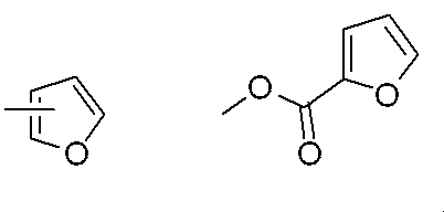
- HDJLSECJEQSPKW-UHFFFAOYSA-N COC(c1ccc[o]1)=O Chemical compound COC(c1ccc[o]1)=O HDJLSECJEQSPKW-UHFFFAOYSA-N 0.000 description 1
Classifications
-
- C—CHEMISTRY; METALLURGY
- C08—ORGANIC MACROMOLECULAR COMPOUNDS; THEIR PREPARATION OR CHEMICAL WORKING-UP; COMPOSITIONS BASED THEREON
- C08G—MACROMOLECULAR COMPOUNDS OBTAINED OTHERWISE THAN BY REACTIONS ONLY INVOLVING UNSATURATED CARBON-TO-CARBON BONDS
- C08G73/00—Macromolecular compounds obtained by reactions forming a linkage containing nitrogen with or without oxygen or carbon in the main chain of the macromolecule, not provided for in groups C08G12/00 - C08G71/00
- C08G73/06—Polycondensates having nitrogen-containing heterocyclic rings in the main chain of the macromolecule
- C08G73/10—Polyimides; Polyester-imides; Polyamide-imides; Polyamide acids or similar polyimide precursors
-
- C—CHEMISTRY; METALLURGY
- C08—ORGANIC MACROMOLECULAR COMPOUNDS; THEIR PREPARATION OR CHEMICAL WORKING-UP; COMPOSITIONS BASED THEREON
- C08L—COMPOSITIONS OF MACROMOLECULAR COMPOUNDS
- C08L79/00—Compositions of macromolecular compounds obtained by reactions forming in the main chain of the macromolecule a linkage containing nitrogen with or without oxygen or carbon only, not provided for in groups C08L61/00 - C08L77/00
- C08L79/04—Polycondensates having nitrogen-containing heterocyclic rings in the main chain; Polyhydrazides; Polyamide acids or similar polyimide precursors
- C08L79/08—Polyimides; Polyester-imides; Polyamide-imides; Polyamide acids or similar polyimide precursors
-
- G—PHYSICS
- G02—OPTICS
- G02F—OPTICAL DEVICES OR ARRANGEMENTS FOR THE CONTROL OF LIGHT BY MODIFICATION OF THE OPTICAL PROPERTIES OF THE MEDIA OF THE ELEMENTS INVOLVED THEREIN; NON-LINEAR OPTICS; FREQUENCY-CHANGING OF LIGHT; OPTICAL LOGIC ELEMENTS; OPTICAL ANALOGUE/DIGITAL CONVERTERS
- G02F1/00—Devices or arrangements for the control of the intensity, colour, phase, polarisation or direction of light arriving from an independent light source, e.g. switching, gating or modulating; Non-linear optics
- G02F1/01—Devices or arrangements for the control of the intensity, colour, phase, polarisation or direction of light arriving from an independent light source, e.g. switching, gating or modulating; Non-linear optics for the control of the intensity, phase, polarisation or colour
- G02F1/13—Devices or arrangements for the control of the intensity, colour, phase, polarisation or direction of light arriving from an independent light source, e.g. switching, gating or modulating; Non-linear optics for the control of the intensity, phase, polarisation or colour based on liquid crystals, e.g. single liquid crystal display cells
- G02F1/133—Constructional arrangements; Operation of liquid crystal cells; Circuit arrangements
- G02F1/1333—Constructional arrangements; Manufacturing methods
- G02F1/1337—Surface-induced orientation of the liquid crystal molecules, e.g. by alignment layers
-
- G—PHYSICS
- G02—OPTICS
- G02F—OPTICAL DEVICES OR ARRANGEMENTS FOR THE CONTROL OF LIGHT BY MODIFICATION OF THE OPTICAL PROPERTIES OF THE MEDIA OF THE ELEMENTS INVOLVED THEREIN; NON-LINEAR OPTICS; FREQUENCY-CHANGING OF LIGHT; OPTICAL LOGIC ELEMENTS; OPTICAL ANALOGUE/DIGITAL CONVERTERS
- G02F1/00—Devices or arrangements for the control of the intensity, colour, phase, polarisation or direction of light arriving from an independent light source, e.g. switching, gating or modulating; Non-linear optics
- G02F1/01—Devices or arrangements for the control of the intensity, colour, phase, polarisation or direction of light arriving from an independent light source, e.g. switching, gating or modulating; Non-linear optics for the control of the intensity, phase, polarisation or colour
- G02F1/13—Devices or arrangements for the control of the intensity, colour, phase, polarisation or direction of light arriving from an independent light source, e.g. switching, gating or modulating; Non-linear optics for the control of the intensity, phase, polarisation or colour based on liquid crystals, e.g. single liquid crystal display cells
- G02F1/133—Constructional arrangements; Operation of liquid crystal cells; Circuit arrangements
- G02F1/1333—Constructional arrangements; Manufacturing methods
- G02F1/1337—Surface-induced orientation of the liquid crystal molecules, e.g. by alignment layers
- G02F1/133711—Surface-induced orientation of the liquid crystal molecules, e.g. by alignment layers by organic films, e.g. polymeric films
- G02F1/133723—Polyimide, polyamide-imide
-
- G—PHYSICS
- G02—OPTICS
- G02F—OPTICAL DEVICES OR ARRANGEMENTS FOR THE CONTROL OF LIGHT BY MODIFICATION OF THE OPTICAL PROPERTIES OF THE MEDIA OF THE ELEMENTS INVOLVED THEREIN; NON-LINEAR OPTICS; FREQUENCY-CHANGING OF LIGHT; OPTICAL LOGIC ELEMENTS; OPTICAL ANALOGUE/DIGITAL CONVERTERS
- G02F1/00—Devices or arrangements for the control of the intensity, colour, phase, polarisation or direction of light arriving from an independent light source, e.g. switching, gating or modulating; Non-linear optics
- G02F1/01—Devices or arrangements for the control of the intensity, colour, phase, polarisation or direction of light arriving from an independent light source, e.g. switching, gating or modulating; Non-linear optics for the control of the intensity, phase, polarisation or colour
- G02F1/13—Devices or arrangements for the control of the intensity, colour, phase, polarisation or direction of light arriving from an independent light source, e.g. switching, gating or modulating; Non-linear optics for the control of the intensity, phase, polarisation or colour based on liquid crystals, e.g. single liquid crystal display cells
- G02F1/137—Devices or arrangements for the control of the intensity, colour, phase, polarisation or direction of light arriving from an independent light source, e.g. switching, gating or modulating; Non-linear optics for the control of the intensity, phase, polarisation or colour based on liquid crystals, e.g. single liquid crystal display cells characterised by the electro-optical or magneto-optical effect, e.g. field-induced phase transition, orientation effect, guest-host interaction or dynamic scattering
- G02F1/139—Devices or arrangements for the control of the intensity, colour, phase, polarisation or direction of light arriving from an independent light source, e.g. switching, gating or modulating; Non-linear optics for the control of the intensity, phase, polarisation or colour based on liquid crystals, e.g. single liquid crystal display cells characterised by the electro-optical or magneto-optical effect, e.g. field-induced phase transition, orientation effect, guest-host interaction or dynamic scattering based on orientation effects in which the liquid crystal remains transparent
- G02F1/1393—Devices or arrangements for the control of the intensity, colour, phase, polarisation or direction of light arriving from an independent light source, e.g. switching, gating or modulating; Non-linear optics for the control of the intensity, phase, polarisation or colour based on liquid crystals, e.g. single liquid crystal display cells characterised by the electro-optical or magneto-optical effect, e.g. field-induced phase transition, orientation effect, guest-host interaction or dynamic scattering based on orientation effects in which the liquid crystal remains transparent the birefringence of the liquid crystal being electrically controlled, e.g. ECB-, DAP-, HAN-, PI-LC cells
Definitions
- the present invention relates to a vertical alignment type liquid crystal display element produced by irradiating ultraviolet rays in a state where a voltage is applied to liquid crystal molecules, and a liquid crystal alignment agent used for manufacturing the liquid crystal display element.
- a liquid crystal display element that responds by an electric field to liquid crystal molecules that are aligned perpendicular to the substrate
- ultraviolet light is applied while applying a voltage to the liquid crystal molecules during the manufacturing process.
- the direction in which the liquid crystal molecules tilt in response to an electric field is controlled by protrusions provided on the substrate or slits provided on the display electrode, but a photopolymerizable compound is added to the liquid crystal composition.
- the polymer structure in which the direction in which the liquid crystal molecules are tilted is formed on the liquid crystal alignment film. It is said that the response speed of the liquid crystal display element is faster than the method of controlling the direction (see, for example, Patent Document 1).
- An object of the present invention is to add a photopolymerizable compound in a liquid crystal composition or a liquid crystal alignment film in a vertical alignment type liquid crystal display device produced by irradiating ultraviolet rays while applying voltage to liquid crystal molecules. It is an object of the present invention to provide a liquid crystal display element capable of increasing the response speed, a manufacturing method thereof, and a liquid crystal aligning agent suitable for the liquid crystal display element.
- the present invention is characterized by the following configuration.
- An alignment agent is applied on two substrates to form a liquid crystal alignment layer, Two substrates are arranged so that the liquid crystal alignment layer faces each other, A liquid crystal layer is sandwiched between the two substrates,
- a method for producing a liquid crystal display element of a vertical alignment method characterized by irradiating ultraviolet rays while applying a voltage to a liquid crystal layer.
- liquid crystal aligning agent is a liquid crystal aligning agent containing at least one of the following polyamic acid and a polyimide obtained by imidizing the polyamic acid: .
- a polyamic acid obtained by reacting a diamine component containing a diamine having a side chain (A) for vertically aligning liquid crystal and a diamine having a photoreactive side chain (B) with tetracarboxylic dianhydride.
- a polyamic acid obtained by reacting a diamine component containing a diamine having a side chain (A) for vertically aligning liquid crystal and a diamine having a photoreactive side chain (B) with tetracarboxylic dianhydride.
- R 1 represents an alkylene group having 2 to 6 carbon atoms, —O—, —COO—, —OCO—, — NHCO—, —CONH—, or an alkylene-ether group having 1 to 3 carbon atoms
- R 2 , R 3 and R 4 each independently represents a phenylene group or a cycloalkylene group
- R 5 represents a hydrogen atom.
- R 6 is —CH 2 —, —O—, —COO—, —NHCO—, —NH—, —CH 2 O—, —N (CH 3 ) —, —CON (CH 3 ) —, or —N (CH 3 ) CO—
- R 7 represents a linear alkylene having 1 to 20 carbon atoms (the alkylene may be unsubstituted or substituted by a fluorine atom), and any —CH of alkylene 2 — may be replaced by —CF 2 —, —CH ⁇ CH—, or the following substituents (these substituents are not adjacent).
- R 8 represents —CH 2 —, —O—, —COO—, —OCO—, —NHCO—, —NH—, —N (CH 3 ) —, —CON (CH 3 ) —, —N (CH 3 ).
- R 9 represents a vinylphenyl group, —CR 10 ⁇ CH 2 group, a carbocyclic group, a heterocyclic group, or a group represented by the following formula: R 9 10 represents a methyl group which may be substituted with a hydrogen atom or a fluorine atom.
- the side chain (A) for vertically aligning the liquid crystal is represented by the formula (a), l, m, and n are all 1, R 2 is phenylene, and R 3 is phenylene. Or cyclohexylene, R 4 is cyclohexylene, R 5 is an alkyl group having 2 to 24 carbon atoms, or when l, m, and n are all 0, R 5 is the number of carbon atoms.
- the method for producing a liquid crystal display device according to any one of [2] to [5], which is an alkyl group of 12 to 22.
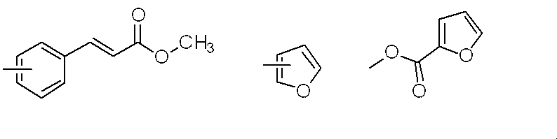
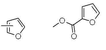
- the photoreactive side chain (B) is represented by the formula (b), and R 9 is a vinylphenyl group, —CH ⁇ CH 2 , —C (CH 3 ) ⁇ CH 2 , or The method for producing a liquid crystal display element according to any one of the above [3] to [5], which is any group of the above.
- [7] Contains at least one selected from the group consisting of a polyamic acid having a side chain (A) for vertically aligning liquid crystals and a photoreactive side chain (B), and a polyimide obtained by imidizing it.
- Two substrates having a liquid crystal alignment layer formed from a liquid crystal alignment agent;
- a liquid crystal cell having a liquid crystal layer sandwiched between the two substrates arranged so that the liquid crystal alignment layers face each other; Means for irradiating ultraviolet rays while applying a voltage to the liquid crystal layer;
- a liquid crystal display element of a vertical alignment system characterized by comprising: [8] A liquid crystal containing at least one selected from the group consisting of a polyamic acid having a side chain (A) for vertically aligning the liquid crystal and a photoreactive side chain (B) and a polyimide obtained by imidizing the polyamic acid.
- R 6 is —CH 2 —, —O—, —COO—, —NHCO—, —NH—, —CH 2 O—, —N (CH 3 ) —, —CON (CH 3 ) —, or —N (CH 3 ) CO—
- R 7 represents a linear alkylene having 1 to 20 carbon atoms (the alkylene may be unsubstituted or substituted by a fluorine atom), and any —CH of alkylene 2 — may be replaced by —CF 2 —, —CH ⁇ CH—, or the following substituents (these substituents are not adjacent).
- R 8 represents —CH 2 —, —O—, —COO—, —OCO—, —NHCO—, —NH—, —N (CH 3 ) —, —CON (CH 3 ) —, or —N (CH 3 ) CO—
- R 11 represents a vinylphenyl group, —CH ⁇ CH 2 , —C (CH 3 ) ⁇ CH 2 , or any of the following groups.
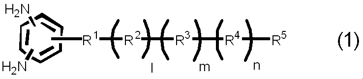
- liquid crystal aligning agent according to any one of the above [7] to [9], wherein the diamine having a side chain (A) for vertically aligning the liquid crystal is represented by the following formula (1).
- R 1 represents an alkylene group having 2 to 6 carbon atoms, —O—, —COO—, —OCO—, — NHCO—, —CONH—, or an alkylene-ether group having 1 to 3 carbon atoms
- R 2 , R 3 and R 4 each independently represents a phenylene group or a cycloalkylene group
- R 5 represents a hydrogen atom.
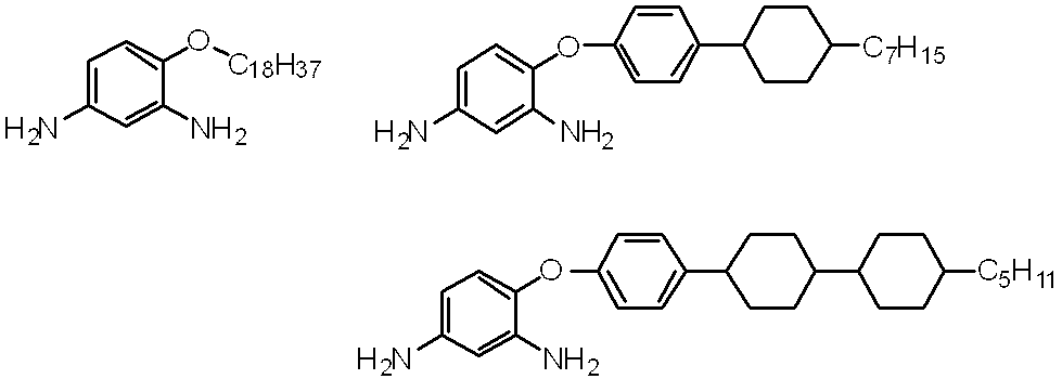
- a diamine having a side chain (A) for vertically aligning the liquid crystal is represented by the formula (1), l, m, and n are all 1, R 2 is phenylene, R When 3 is phenylene or cyclohexylene, R 4 is cyclohexylene, R 5 is an alkyl group having 2 to 24 carbon atoms, or when all of l, m, and n are 0, R 5 is The liquid crystal aligning agent according to the above [10], which is a diamine which is an alkyl group having 12 to 22 carbon atoms. [12] The liquid crystal aligning agent according to any one of [8] to [11], wherein the diamine having a side chain (A) for vertically aligning the liquid crystal is a diamine having any one of the following structures.
- a liquid crystal display element capable of increasing the response speed (shortening the response time) without adding a photopolymerizable compound to the liquid crystal composition or the liquid crystal alignment film.
- the liquid crystal aligning agent of the present invention can be used in a liquid crystal display element of a vertical alignment method produced by irradiating ultraviolet rays while applying a voltage to liquid crystal molecules, so that light can be emitted into a liquid crystal composition or a liquid crystal alignment film. Even without adding a polymerizable compound, it is possible to obtain a liquid crystal display element in which the response speed of the liquid crystal is increased (response time is short).
- a side chain that aligns liquid crystal vertically is a side chain that has the ability to orient liquid crystal molecules perpendicular to the substrate, and the structure is not limited as long as it has this ability.
- the side chain A for example, a long-chain alkyl group, a long-chain fluoroalkyl group, a cyclic group having an alkyl group or a fluoroalkyl group at the terminal, a steroid group, or the like is known, and is preferably used in the present invention. It is done.
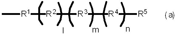
- R 1 in the above formula (a) is an alkylene group having 2 to 6 carbon atoms, preferably 2 to 4 carbon atoms, —O—, —COO—, —OCO—, —NHCO—, —CONH—, or a carbon atom.
- —O—, —COO—, —CONH—, or an alkylene-ether group having 1 to 3 carbon atoms is preferable from the viewpoint of ease of synthesis.
- R 2 , R 3 and R 4 each independently represent a phenylene group or a cycloalkylene group.
- the combination of l, m, n, R 2 , R 3 and R 4 shown in the following table is preferable from the viewpoint of ease of synthesis and the ability to align the liquid crystal vertically.
- R 5 represents a hydrogen atom, an alkyl group having 2 to 24 carbon atoms, preferably 5 to 8 carbon atoms or a fluorine-containing alkyl group, an aromatic ring, an aliphatic ring, a heterocyclic ring, or a macrocyclic group composed thereof.
- the structure of R 5 is preferably a hydrogen atom, an alkyl group having 2 to 14 carbon atoms, or a fluorine-containing alkyl group having 2 to 14 carbon atoms.
- R 5 is preferably a hydrogen atom, an alkyl group having 2 to 12 carbon atoms, preferably 2 to 10 carbon atoms, or a fluorine-containing alkyl group.
- R 5 is preferably an alkyl group having 12 to 22 carbon atoms, preferably 12 to 20 carbon atoms, or a fluorine-containing alkyl group, an aromatic ring, an aliphatic ring.
- a heterocyclic ring, or a macrocyclic group composed of them more preferably an alkyl group having 12 to 20 carbon atoms, preferably 12 to 18 carbon atoms, or a fluorine-containing alkyl group.
- the ability to align the liquid crystal vertically varies depending on the structure of the side chain A, but generally, the ability to align the liquid crystal vertically increases as the amount of the side chain A contained in the polymer increases, and decreases as the amount decreases. . Further, the side chain A containing a cyclic structure tends to align the liquid crystal vertically even with a small content as compared with the side chain A of the long-chain alkyl group.
- the amount of the side chain A in the polyamic acid or polyimide used in the present invention is not particularly limited as long as the liquid crystal alignment film can align the liquid crystal vertically, but it is 5 to 5 to the total amount of diamine used. 50 mol% is preferable, and 10 to 30 mol% is more preferable.
- the amount of side chain A present in the liquid crystal display device having the liquid crystal alignment film, if it is desired to increase the response speed of the liquid crystal, the presence of side chain A is within the range where vertical alignment can be maintained. The amount is preferably as small as possible.
- the photoreactive side chain (also referred to as side chain B) is a side chain having a functional group capable of forming a covalent bond by causing a photoreaction upon irradiation with ultraviolet rays.
- the structure is not limited.
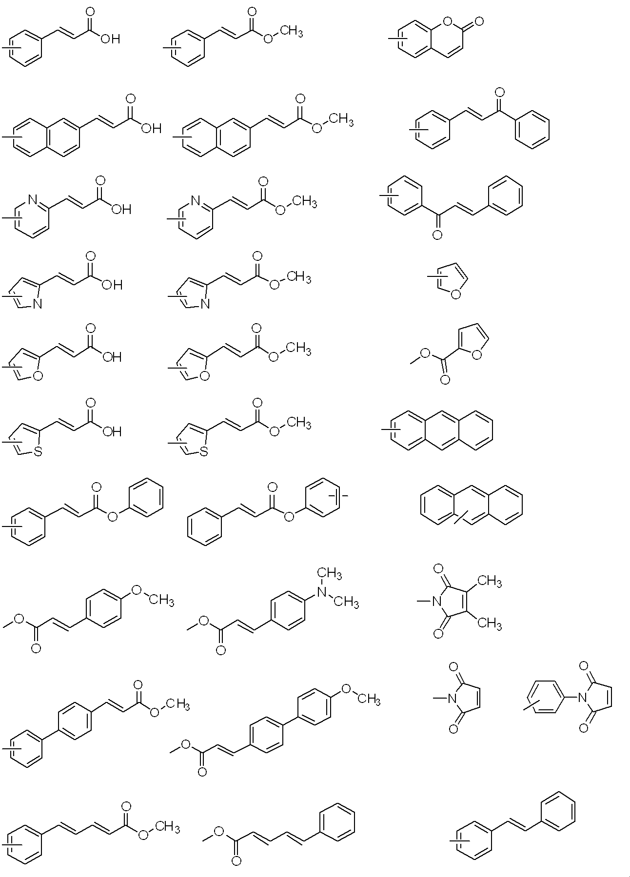
- a photoreactive group a side chain having a vinyl group, an acrylic group, a methacryl group, an anthracenyl group, a cinnamoyl group, a chalcone group, a coumarin group, a maleimide group, a stilbene group, or the like is known. It is also preferably used in the present invention. These groups may be directly bonded to the main chain of polyamic acid or polyimide as long as they have the above-mentioned ability, and may be bonded via an appropriate bonding group. Examples of the side chain B include those represented by the following formula (b).
- R 6 in the above formula (b) is —CH 2 —, —O—, —NH—, —N (CH 3 ) —, —CONH—, —NHCO—, —CH 2 O—, —COO—, —OCO—, —CON (CH 3 ) —, or —N (CH 3 ) CO— is represented.
- R 6 can be formed by a general organic synthetic method, but from the viewpoint of ease of synthesis, —CH 2 —, —O—, —COO—, —NHCO—, —NH—, or —CH 2 O- is preferred.
- R 7 in the above formula (b) represents a linear alkylene having 1 to 20 carbon atoms (the alkylene may be unsubstituted or substituted by a fluorine atom), and any —CH 2 of alkylene — May be replaced by —CF 2 —, —CH ⁇ CH—, or the following substituents (these substituents are not adjacent to each other).
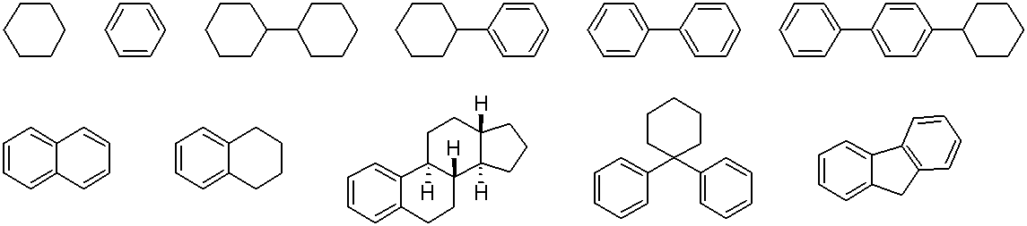
- Specific examples of the carbocyclic group and heterocyclic group include the following structures, but are not limited thereto.
- Alkylene R 7 represents, for faster response speed, reaction efficiency of a flexible spacer (group linking the R 6 and R 8) provided, photoreactive groups between R 6 and R 8 R 7 is preferably a linear alkylene having 1 to 20 carbon atoms, preferably 2 to 8 carbon atoms.
- R 8 in the above formula (b) is —CH 2 —, —O—, —NH—, —N (CH 3 ) —, —CONH—, —NHCO—, —CH 2 O—, —COO—, It represents —OCO—, —CON (CH 3 ) —, —N (CH 3 ) CO—, a carbocyclic group, or a heterocyclic group.
- —CH 2 —, —O—, —COO—, —OCO—, NHCO—, —NH—, a carbocyclic group, or a heterocyclic group is preferable from the viewpoint of ease of synthesis.
- R 8 is more preferably —CH 2 —, —O—, —COO—, —OCO—, NHCO—, or —NH— from the viewpoint of response speed.
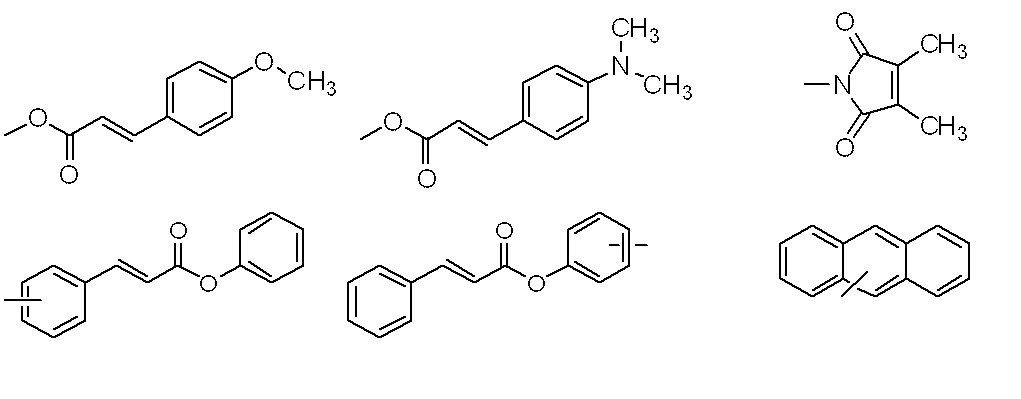
- R 9 in the above formula (b) represents a vinylphenyl group, —CR 10 ⁇ CH 2 , a carbocyclic group, a heterocyclic group, or a group represented by the following formula, and R 10 represents a hydrogen atom or a fluorine atom. Represents a methyl group which may be substituted with
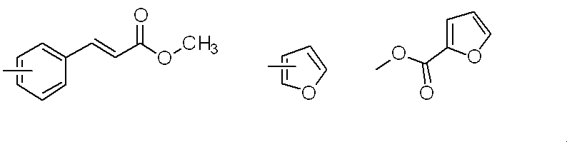
- R 9 is more preferably a vinylphenyl group, —CH ⁇ CH 2 , —C (CH 3 ) ⁇ CH 2 or the following group from the viewpoint of photoreactivity.
- R 9 is particularly preferably a vinyl group, —C (CH 3 ) ⁇ CH 2 or the following group.
- the amount of the side chain B in the polyamic acid or polyimide used in the present invention is not particularly limited as long as it can increase the response speed of the liquid crystal in the liquid crystal display element, but is 10% relative to the total amount of diamine used. ⁇ 95 mol% is preferable, and 60 to 95 mol% is more preferable.
- the amount of the side chain B is preferably as large as possible within a range that does not affect other characteristics when it is desired to increase the response speed of the liquid crystal in the liquid crystal display element.
- the polyamic acid having the side chain A and the side chain B is obtained by reacting the diamine having the side chain A and / or the diamine having the side chain B with tetracarboxylic dianhydride, or the diamine,
- tetracarboxylic dianhydride having a chain A and / or a tetracarboxylic dianhydride having a side chain B
- a diamine having a side chain A and / or a diamine having a side chain B and a side chain A Can be obtained by a reaction with a tetracarboxylic dianhydride having a side chain B and / or a tetracarboxylic dianhydride having a side chain B.
- diamine A As a diamine compound having a side chain A (hereinafter also referred to as diamine A), the diamine side chain has an alkyl group, a fluorine-containing alkyl group, an aromatic ring, an aliphatic ring, a heterocyclic ring, or a macrocyclic substituent composed thereof.
- a diamine can be mentioned as an example. Specific examples include diamines having a side chain represented by the formula (a). More specifically, for example, diamines represented by the following formula (1), (3), (4), or (5) can be exemplified, but the invention is not limited thereto.
- a 10 represents —COO—, —OCO—, —CONH—, —NHCO—, —CH 2 —, —O—, —CO—, or —NH—.
- a 11 represents a single bond or a phenylene group.
- a represents a side chain A, and a ′ represents an alkyl group, a fluorine-containing alkyl group, an aromatic ring, an aliphatic ring, a heterocyclic ring, or a macrocyclic group composed of these groups.
- a 14 represents an alkyl group having 3 to 20 carbon atoms which may be substituted with a fluorine atom
- a 15 represents a 1,4-cyclohexylene group or 1,4-phenylene.
- a 16 represents an oxygen atom or —COO— * (where a bond marked with “*” is bonded to A 3 )
- a 17 represents an oxygen atom or —COO— * (where “*”) Represents a bond with (CH 2 ) a 2 ).
- a 1 is an integer of 0 or 1
- a 2 is an integer of 2 to 10
- a 3 is an integer of 0 or 1.
- the bonding position of the two amino groups (—NH 2 ) in the formula (1) is not limited. Specifically, with respect to the linking group of the side chain, 2, 3 position, 2, 4 position, 2, 5 position, 2, 6 position, 3, 4 position on the benzene ring, 3, 4 position, 5 positions. Among these, from the viewpoint of reactivity when synthesizing a polyamic acid, positions 2, 4, 2, 5, or 3, 5 are preferable. Considering the ease in synthesizing the diamine compound, the positions 2, 4 or 3, 5 are more preferable.
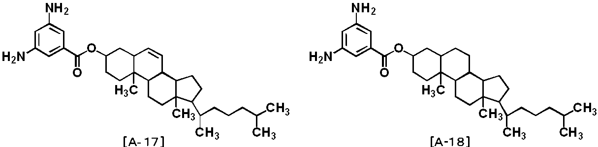
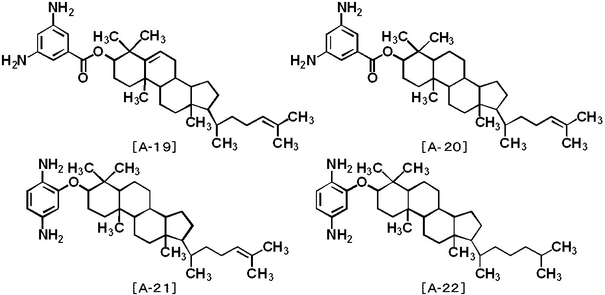
- Specific examples of the structure of the formula (1) include diamines represented by the following formulas [A-1] to [A-24], but are not limited thereto.
- a 1 is an alkyl group having 2 to 24 carbon atoms or a fluorine-containing alkyl group.
- a 2 represents —O—, —OCH 2 —, —CH 2 O—, —COOCH 2 —, or —CH 2 OCO—
- a 3 Is an alkyl group having 1 to 22 carbon atoms, an alkoxy group, a fluorine-containing alkyl group or a fluorine-containing alkoxy group.
- a 4 represents —COO—, —OCO—, —CONH—, —NHCO—, —COOCH 2 —, —CH 2 OCO—, —CH 2 O —, —OCH 2 —, or —CH 2 — is represented.
- a 5 represents an alkyl group having 1 to 22 carbon atoms, an alkoxy group, a fluorine-containing alkyl group or a fluorine-containing alkoxy group.
- a 6 represents —COO—, —OCO—, —CONH—, —NHCO—, —COOCH 2 —, —CH 2 OCO—, —CH 2 O Represents —, —OCH 2 —, —CH 2 —, —O—, or —NH—
- a 7 represents fluorine group, cyano group, trifluoromethyl group, nitro group, azo group, formyl group, acetyl group, acetoxy Represents a group or a hydroxyl group.
- a 8 represents an alkyl group having 3 to 12 carbon atoms, and the cis-trans isomerism of 1,4-cyclohexylene is a trans isomer.
- a 9 represents an alkyl group having 3 to 12 carbon atoms, and the cis-trans isomerism of 1,4-cyclohexylene is a trans isomer.
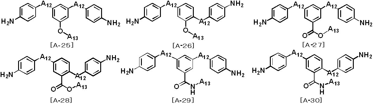
- diamine represented by the formula (3) include diamines represented by the following formulas [A-25] to [A-30], but are not limited thereto.
- a 12 represents —COO—, —OCO—, —CONH—, —NHCO—, —CH 2 —, —O—, —CO—, or — NH— represents A— 13 represents an alkyl group having 1 to 22 carbon atoms or a fluorine-containing alkyl group.
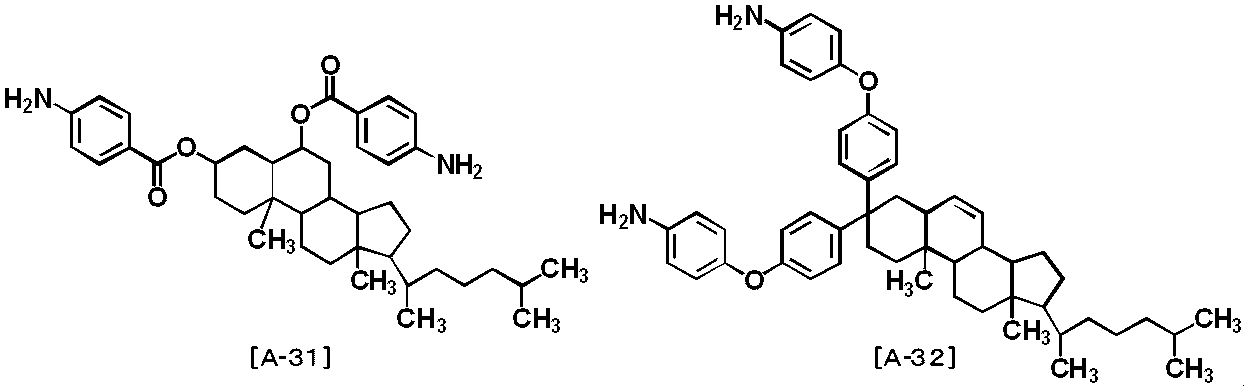
- diamine represented by the formula (4) examples include diamines represented by the following formulas [A-31] to [A-32], but are not limited thereto.
- [A-1], [A-2], [A-3], [A-4], [A-5], [A-5], [A-5], [A-5], [A-5], [A-5], [A-5], [A-5], [A-5] A-25], [A-26], [A-27], [A-28], [A-29], and [A-30] are preferable.
- the above diamine compounds can be used alone or in combination of two or more depending on the liquid crystal alignment properties, pretilt angle, voltage holding characteristics, accumulated charge and the like when the liquid crystal alignment film is formed.
- the diamine component used for the synthesis of the polyamic acid is diamine A.
- 5 to 30 mol% of the diamine component is preferably diamine A, and particularly preferably 5 to 15 mol%.
- the diamine side chain B has a light such as vinyl group, acrylic group, methacryl group, anthracenyl group, cinnamoyl group, chalconyl group, coumarin group, maleimide group, and stilbene group.
- a diamine having a reactive group can be mentioned as an example.
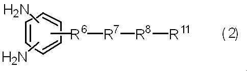
- Specific examples include diamines having a side chain represented by the formula (b). More specifically, examples include diamines represented by the following general formula (2), but are not limited thereto.
- R 6 is —CH 2 —, —O—, —COO—, —NHCO—, —NH—, —CH 2 O—, —N (CH 3 ) —, —CON (CH 3 ) — Or —N (CH 3 ) CO—, wherein R 7 represents a linear alkylene having 1 to 20 carbon atoms (the alkylene may be unsubstituted or substituted by a fluorine atom), Further, any —CH 2 — in the alkylene may be replaced with —CF 2 —, —CH ⁇ CH—, or the following substituents (these substituents are not adjacent).
- R 8 represents —CH 2 —, —O—, —COO—, —OCO—, —NHCO—, —NH—, —N (CH 3 ) —, —CON (CH 3 ) —, or —N (CH 3 ) CO—
- R 11 represents a vinylphenyl group, —CH ⁇ CH 2 , —C (CH 3 ) ⁇ CH 2 , or any of the following groups.
- the bonding position of the two amino groups (—NH 2 ) in the formula (2) is not particularly limited. Specifically, with respect to the linking group of the side chain, 2, 3 position, 2, 4 position, 2, 5 position, 2, 6 position, 3, 4 position on the benzene ring, 3, 4 position, 5 positions. Among these, from the viewpoint of reactivity when synthesizing a polyamic acid, positions 2, 4, 2, 5, or 3, 5 are preferable. Considering the ease in synthesizing the diamine compound, the positions 2, 4 or 3, 5 are more preferable. Specific examples include the following compounds, but are not limited thereto.
- X independently represents a linking group selected from the group consisting of —C—, —O—, —NHCO—, —CONH—, —COO—, —OCO—, and —NH—
- l, m and n each independently represents an integer of 0 to 20.
- One or two of the above diamine compounds may be used depending on the liquid crystal alignment properties, the pretilt angle, the voltage holding characteristics, the accumulated charge characteristics, and the response speed of the liquid crystal when the liquid crystal display element is used. A mixture of more than one can also be used.
- 10 to 95 mol% of the diamine component used for the synthesis of the polyamic acid is diamine B.
- 40 to 95 mol% of the diamine component is more preferably diamine B, and particularly preferably 70 to 95 mol%.
- the polyamic acid used in the present invention can be used in combination with other diamine compounds other than diamine A and diamine B as the diamine component as long as the effects of the present invention are not impaired. Specific examples are given below.
- the above-mentioned other diamine compounds may be used alone or in combination of two or more depending on the properties such as the liquid crystal orientation, the pretilt angle, the voltage holding property, and the accumulated charge when the liquid crystal alignment film is used.
- tetracarboxylic dianhydride In the synthesis of the polyamic acid used in the present invention, the tetracarboxylic dianhydride to be reacted with the diamine component is not particularly limited. Specific examples of tetracarboxylic acid, which is a raw material for obtaining tetracarboxylic dianhydride, are given below.
- the tetracarboxylic dianhydride can be used alone or in combination of two or more depending on the liquid crystal alignment properties, voltage holding characteristics, accumulated charge, and the like when the liquid crystal alignment film is formed.
- ⁇ Synthesis of polyamic acid> In obtaining a polyamic acid by a reaction between a diamine component and tetracarboxylic dianhydride, a known synthesis method can be used. In general, the diamine component and tetracarboxylic dianhydride are reacted in an organic solvent. The reaction between the diamine component and tetracarboxylic dianhydride is advantageous in that it proceeds relatively easily in an organic solvent and no by-products are generated.
- the organic solvent used in the above reaction is not particularly limited as long as the generated polyamic acid dissolves. Furthermore, even if it is an organic solvent which does not dissolve a polyamic acid, it may be mixed with the said solvent and used as long as the produced polyamic acid does not precipitate. In addition, since the water
- the solution in which the diamine component is dispersed or dissolved in the organic solvent is stirred, and the tetracarboxylic dianhydride component is used as it is or in an organic solvent.
- a method of adding by dispersing or dissolving in a solvent a method of adding a diamine component to a solution in which a tetracarboxylic dianhydride component is dispersed or dissolved in an organic solvent, and a tetracarboxylic dianhydride component and a diamine component.
- the method of adding alternately etc. is mentioned, You may use any of these methods.
- the diamine component or tetracarboxylic dianhydride component when they are composed of a plurality of types of compounds, they may be reacted in a premixed state, may be individually reacted sequentially, or may be further reacted individually.
- the body may be mixed and reacted to form a high molecular weight body.
- the temperature at the time of reacting the diamine component and the tetracarboxylic dianhydride component can be selected arbitrarily, and is, for example, in the range of ⁇ 20 ° C. to 150 ° C., preferably ⁇ 5 ° C. to 100 ° C.
- the reaction can be carried out at any concentration, for example 1 to 50% by mass, preferably 5 to 30% by mass.
- the ratio of the total number of moles of the tetracarboxylic dianhydride component to the total number of moles of the diamine component can be selected according to the molecular weight of the polyamic acid to be obtained. Similar to the normal polycondensation reaction, the molecular weight of the polyamic acid produced increases as the molar ratio approaches 1.0. If it shows a preferable range, it is 0.8 to 1.2.
- the method for synthesizing the polyamic acid used in the present invention is not limited to the above-described method, and in the same manner as the general polyamic acid synthesis method, instead of the tetracarboxylic dianhydride, a tetracarboxylic acid having a corresponding structure is used.
- the corresponding polyamic acid can also be obtained by reacting by a known method using a tetracarboxylic acid derivative such as acid or tetracarboxylic acid dihalide.
- Examples of the method for imidizing the polyamic acid to form a polyimide include thermal imidization in which a polyamic acid solution is heated as it is, and catalytic imidization in which a catalyst is added to the polyamic acid solution.
- the imidization ratio from polyamic acid to polyimide is not necessarily 100%.
- the temperature when the polyamic acid is thermally imidized in the solution is 100 ° C. to 400 ° C., preferably 120 ° C. to 250 ° C., and a method of removing water generated by the imidation reaction from the outside of the system is preferable.
- the catalytic imidation of polyamic acid can be carried out by adding a basic catalyst and an acid anhydride to a polyamic acid solution and stirring at -20 to 250 ° C., preferably 0 to 180 ° C.
- the amount of the basic catalyst is 0.5 to 30 mol times, preferably 2 to 20 mol times of the amic acid group, and the amount of the acid anhydride is 1 to 50 mol times, preferably 3 to 30 mol of the amido acid group. Is double.
- the basic catalyst include pyridine, triethylamine, trimethylamine, tributylamine, trioctylamine and the like. Among them, pyridine is preferable because it has an appropriate basicity for proceeding with the reaction.
- Examples of the acid anhydride include acetic anhydride, trimellitic anhydride, pyromellitic anhydride, and the like. Among them, use of acetic anhydride is preferable because purification after completion of the reaction is facilitated.
- the imidization rate by catalytic imidation can be controlled by adjusting the amount of catalyst, reaction temperature, and reaction time.
- the reaction solution may be poured into a poor solvent and precipitated.
- the poor solvent used for precipitation include methanol, acetone, hexane, butyl cellosolve, heptane, methyl ethyl ketone, methyl isobutyl ketone, ethanol, toluene, benzene, and water.
- the polymer precipitated in a poor solvent and collected by filtration can be dried by normal temperature or reduced pressure at room temperature or by heating.
- the polymer collected by precipitation is redissolved in an organic solvent and reprecipitation and collection is repeated 2 to 10 times, impurities in the polymer can be reduced.
- the poor solvent at this time include alcohols, ketones, hydrocarbons and the like, and it is preferable to use three or more kinds of poor solvents selected from these because purification efficiency is further improved.
- a liquid crystal aligning agent is a coating liquid for forming a liquid crystal aligning film, and is a solution in which a resin component for forming a liquid crystal aligning film is dissolved in an organic solvent.
- the resin component is a resin component containing at least one polymer selected from the group consisting of the polyamic acid and the polyimide.
- the content of the resin component is preferably 1% by mass to 20% by mass, more preferably 3% by mass to 15% by mass, and particularly preferably 3% by mass to 10% by mass.
- the above resin components may all be polyamic acid having side chain A and side chain B, or polyimide obtained by imidizing it, and these polyamic acid and polyimide.
- the other polymer may be mixed.
- the content of the other polymer in the resin component is preferably 0.5% by mass to 15% by mass, and more preferably 1% by mass to 10% by mass.
- examples of such other polymers include polyamic acid or polyimide that does not have side chain A and side chain B at the same time.
- the molecular weight of the polymer of the above resin component is the weight measured by GPC (Gel Permeation Chromatography) method in consideration of the strength of the coating film obtained therefrom, workability at the time of coating film formation, and uniformity of the coating film.
- the average molecular weight is preferably 5,000 to 1,000,000, more preferably 10,000 to 150,000.
- the organic solvent used for the liquid crystal aligning agent used for this invention will not be specifically limited if it is an organic solvent in which the resin component mentioned above is dissolved.
- This organic solvent may be one type of solvent or a mixed solvent of two or more types. If the specific example of an organic solvent is given dare, the organic solvent illustrated by the said polyamic acid synthesis can be mentioned. Among them, N-methyl-2-pyrrolidone, ⁇ -butyrolactone, N-ethyl-2-pyrrolidone, 1,3-dimethyl-2-imidazolidinone, 3-methoxy-N, N-dimethylpropanamide, etc. It is preferable from the viewpoint of solubility.
- the solvent as shown below improves the uniformity and smoothness of the coating film, it is preferable to use the solvent by mixing it with a solvent having high solubility of the resin component.
- a solvent having high solubility of the resin component For example, isopropyl alcohol, methoxymethylpentanol, methyl cellosolve, ethyl cellosolve, butyl cellosolve, methyl cellosolve acetate, butyl cellosolve acetate, ethyl cellosolve acetate, butyl carbitol, ethyl carbitol, ethyl carbitol acetate, ethylene glycol, ethylene glycol monoacetate, Ethylene glycol monoisopropyl ether, ethylene glycol monobutyl ether, propylene glycol, propylene glycol monoacetate, propylene glycol monomethyl ether, propylene glycol monobutyl ether, propylene glycol-tert-buty
- the liquid crystal aligning agent may contain components other than those described above. Examples thereof include compounds that improve the film thickness uniformity and surface smoothness when a liquid crystal aligning agent is applied, and compounds that improve the adhesion between the liquid crystal aligning film and the substrate.
- Examples of compounds that improve film thickness uniformity and surface smoothness include fluorine-based surfactants, silicone-based surfactants, and nonionic surfactants. More specifically, for example, F-top EF301, EF303, EF352 (manufactured by Tochem Products), MegaFuck F171, F173, R-30 (manufactured by Dainippon Ink), Florard FC430, FC431 (manufactured by Sumitomo 3M) Asahi Guard AG710, Surflon S-382, SC101, SC102, SC103, SC104, SC105, SC106 (manufactured by Asahi Glass Co., Ltd.).
- the proportions used are preferably 0.01 to 2 parts by mass, more preferably 0.01 to 1 part per 100 parts by mass of the resin component contained in the liquid crystal aligning agent. Part by mass.
- the compound that improves the adhesion between the liquid crystal alignment film and the substrate include a functional silane-containing compound and an epoxy group-containing compound.
- a functional silane-containing compound and an epoxy group-containing compound For example, 3-aminopropyltrimethoxysilane, 3-aminopropyltriethoxysilane, 2-aminopropyltrimethoxysilane, 2-aminopropyltriethoxysilane, N- (2-aminoethyl) -3-aminopropyltrimethoxysilane N- (2-aminoethyl) -3-aminopropylmethyldimethoxysilane, 3-ureidopropyltrimethoxysilane, 3-ureidopropyltriethoxysilane, N-ethoxycarbonyl-3-aminopropyltrimethoxysilane, N-ethoxy Carbonyl-3-aminopropyltriethoxysilane, N
- the liquid crystal aligning agent used in the present invention is a dielectric or conductive material for the purpose of changing the electrical properties such as the dielectric constant and conductivity of the liquid crystal alignment film as long as the effects of the present invention are not impaired. Substances may be added.
- liquid crystal aligning agents among ⁇ polyamic acid obtained by reacting diamine component containing diamine A and diamine B and tetracarboxylic dianhydride ⁇ and ⁇ polyimide obtained by imidizing it ⁇
- a liquid crystal aligning agent containing at least one kind wherein diamine B is a diamine represented by the formula (2), and R 8 in the formula (2) is —CH 2 —, —O—, —COO— , —OCO—, —NHCO—, or —NH—, wherein R 11 is —CR 10 ⁇ CH 2 group, and R 10 is a hydrogen atom or a methyl group optionally substituted with a fluorine atom
- the liquid crystal aligning agent of the present invention is not only useful as a liquid crystal aligning agent for producing the liquid crystal display element of the present invention, but can also be suitably used for a liquid crystal aligning agent
- the liquid crystal aligning agent of the present invention can be used as a liquid crystal aligning film after being applied and baked on a substrate and then subjected to alignment treatment by rubbing treatment, light irradiation or the like, or without alignment treatment in vertical alignment applications.
- the substrate to be used is not particularly limited as long as it is a highly transparent substrate, and a glass substrate, a plastic substrate such as an acrylic substrate or a polycarbonate substrate, or the like can be used.
- an opaque material such as a silicon wafer can be used as long as only one substrate is used. In this case, a material that reflects light, such as aluminum, can also be used.
- the method for applying the liquid crystal aligning agent is not particularly limited, but industrially, methods such as screen printing, offset printing, flexographic printing, and inkjet are generally used. Other coating methods include dip, roll coater, slit coater, spinner and the like, and these may be used depending on the purpose.
- Firing after applying the liquid crystal aligning agent can be performed at an arbitrary temperature of 100 to 350 ° C., preferably 120 to 300 ° C., more preferably 150 to 250 ° C.
- This baking can be performed with a hot plate, a hot-air circulating furnace, an infrared furnace, or the like.
- the thickness of the film after firing is not particularly limited, but is preferably 5 to 300 nm, more preferably 10 to 100 nm.
- the fired coating film is treated with rubbing or irradiation with polarized ultraviolet rays.
- the liquid crystal display element of the present invention is selected from the group consisting of a polyamic acid having a side chain (A) for vertically aligning liquid crystals and a photoreactive side chain (B) and a polyimide obtained by imidizing it.
- the substrate used in the liquid crystal display element of the present invention is not particularly limited as long as it is a highly transparent substrate, but is usually a substrate on which a transparent electrode for driving liquid crystal is formed. Specific examples include the same substrates as those described in the above ⁇ Liquid crystal alignment film>.
- a substrate provided with a conventional electrode pattern or protrusion pattern may be used.
- the liquid crystal display of the present invention can operate even in a structure in which a line / slit electrode pattern of 1 to 10 ⁇ m is formed on one side substrate and no slit pattern or protrusion pattern is formed on the opposite substrate.
- the liquid crystal display can simplify the manufacturing process and obtain high transmittance.
- a high-performance element such as a TFT type element
- an element in which an element such as a transistor is formed between an electrode for driving a liquid crystal and a substrate is used.
- a transmissive liquid crystal element it is common to use a substrate as described above.
- an opaque substrate such as a silicon wafer can be used if only one substrate is used. It is. At that time, a material such as aluminum that reflects light may be used for the electrode formed on the substrate.
- the above-mentioned liquid crystal alignment layer is a resin film for aligning liquid crystals perpendicularly to the substrate, and is formed using the liquid crystal aligning agent.
- the coating method described in ⁇ Liquid crystal alignment film> and the baking method after coating can be applied.
- a known method for producing a liquid crystal cell can be exemplified.
- liquid crystal cell production prepare a pair of substrates on which a liquid crystal alignment layer has been formed, spray spacers on the liquid crystal alignment layer of one substrate, and place the other liquid crystal alignment layer on the other side.
- the thickness of the spacer at this time is preferably 1 to 30 ⁇ m, more preferably 2 to 10 ⁇ m.
- the liquid crystal used in the liquid crystal display element of the present invention can increase the response speed of the liquid crystal even if it is a liquid crystal to which no photopolymerizable compound is added. It doesn't matter.
- the step of applying a voltage to the liquid crystal layer and irradiating ultraviolet rays while forming an electric field is performed by applying a voltage between the electrodes installed on the substrate, for example, by applying a voltage to the liquid crystal layer and maintaining this voltage.
- a method of irradiating with ultraviolet rays is mentioned.
- a function generator can be used as means for applying a voltage to the liquid crystal layer, and an existing apparatus such as a high-pressure mercury lamp can be used as means for irradiating ultraviolet rays.
- the voltage applied between the electrodes is, for example, 5 to 30 Vp-p, preferably 5 to 20 Vp-p.
- the wavelength of the ultraviolet light is preferably 250 to 400 nm, more preferably 300 to 400 nm.
- the ultraviolet irradiation amount is, for example, 1 to 60 J / cm 2 , preferably 40 J / cm 2 or less, and the smaller the ultraviolet irradiation amount, the lowering of reliability due to the destruction of the members constituting the liquid crystal display can be suppressed, and It is preferable because the production efficiency is increased by reducing the ultraviolet irradiation time.
- the photoreactive group of the side chain B reacts and the direction in which the liquid crystal molecules are tilted is stored, so that the response speed of the liquid crystal display element is increased.
- the organic layer was dehydrated and dried by adding anhydrous magnesium sulfate, filtered, and then the solvent was distilled off using a rotary evaporator.
- the results measured by 1 H-NMR of desired product are shown below. From this result, it was confirmed that the obtained solid was the target diamino compound, that is, undec-10-enyl-3,5-diaminobenzoate.
- Example 1 The liquid crystal aligning agent [A1] obtained in Synthesis Example 1 was spin-coated on the ITO surface of an ITO electrode substrate on which an ITO electrode pattern having a pixel size of 100 ⁇ 300 microns and a line / space of 5 microns was formed. . After drying for 90 seconds on an 80 ° C. hot plate, baking was performed for 60 minutes in a 160 ° C. hot-air circulating oven to form a liquid crystal alignment film having a thickness of 100 nm. The liquid crystal aligning agent [A1] obtained in Synthesis Example 1 was spin-coated on the ITO surface on which no electrode pattern was formed, dried on a hot plate at 80 ° C. for 90 seconds, and then heated at 160 ° C.
- Liquid crystal MLC-6608 (trade name, manufactured by Merck & Co., Inc.) was injected into this empty cell by a reduced pressure injection method to produce a liquid crystal cell.
- the response speed characteristics of these liquid crystal cells were measured by the method described later. Thereafter, 20 J of UV (ultraviolet rays) was irradiated from the outside of the liquid crystal cell in a state where a voltage of 20 Vp-p was applied to the liquid crystal cell. Thereafter, the response speed characteristic was measured again, and the response speed before and after UV irradiation was compared. The results are shown in Table 2.
- Examples 2 to 14> and ⁇ Comparative Example 1> As shown in Table 2, the liquid crystal aligning agent [A1], the liquid crystal aligning agents [A2] to [A14] obtained in Synthesis Examples 2 to 14 and the liquid crystal aligning agent obtained in Comparative Synthesis Example 1 [Table 1] A liquid crystal cell was prepared in the same manner as in Example 1 except that the change was made to A15], and the response speed was measured. The results are shown in Table 2.
- the liquid crystal display element of the present invention can be used as a screen of a liquid crystal television or a screen of various information display devices.
- the liquid crystal aligning agent of the present invention can be used for manufacturing a vertical alignment type liquid crystal display device manufactured by irradiating ultraviolet rays while applying voltage to liquid crystal molecules, and does not include such a process. It can also be used for liquid crystal display devices manufactured in It should be noted that the entire contents of the specification, claims, and abstract of Japanese Patent Application No. 2010-043372 filed on February 26, 2010 are incorporated herein as the disclosure of the specification of the present invention. Is.
Landscapes
- Physics & Mathematics (AREA)
- Chemical & Material Sciences (AREA)
- Nonlinear Science (AREA)
- Organic Chemistry (AREA)
- Health & Medical Sciences (AREA)
- Chemical Kinetics & Catalysis (AREA)
- Medicinal Chemistry (AREA)
- Polymers & Plastics (AREA)
- Crystallography & Structural Chemistry (AREA)
- General Physics & Mathematics (AREA)
- Optics & Photonics (AREA)
- Mathematical Physics (AREA)
- Spectroscopy & Molecular Physics (AREA)
- Liquid Crystal (AREA)
- Macromolecular Compounds Obtained By Forming Nitrogen-Containing Linkages In General (AREA)
- Macromonomer-Based Addition Polymer (AREA)
Abstract
Description
〔1〕液晶を垂直に配向させる側鎖(A)及び光反応性の側鎖(B)を有するポリアミック酸及びそれをイミド化させて得られるポリイミドからなる群から選ばれる少なくとも一種を含有する液晶配向剤を2枚の基板上に塗布して液晶配向層を形成し、
上記液晶配向層が対向するように2枚の基板を配置し、
上記2枚の基板の間に液晶層を挟持し、
液晶層に電圧を印加しながら紫外線を照射することを特徴とする垂直配向方式の液晶表示素子の製造方法。
〔2〕前記液晶配向剤が、下記のポリアミック酸及びそれをイミド化させて得られるポリイミドのうちの少なくとも一種を含有する液晶配向剤である、上記〔1〕に記載の液晶表示素子の製造方法。
液晶を垂直に配向させる側鎖(A)を有するジアミン及び光反応性の側鎖(B)を有するジアミンを含む
ジアミン成分とテトラカルボン酸二無水物とを反応させて得られるポリアミック酸。
〔3〕前記液晶を垂直に配向させる側鎖(A)が、下記式(a)で表される、上記〔1〕又は〔2〕に記載の液晶表示素子の製造方法。

〔4〕前記光反応性の側鎖(B)が、下記式(b)で表される、上記〔1〕~〔3〕のいずれかに記載の液晶表示素子の製造方法。

置換基;-O-、-COO-、-NHCO-、-NH-、炭素環基、又は複素環基。
R8は-CH2-、-O-、-COO-、-OCO-、-NHCO-、-NH-、-N(CH3)-、-CON(CH3)-、-N(CH3)CO-、炭素環基、又は複素環基を表し、R9はビニルフェニル基、-CR10=CH2基、炭素環基、複素環基、又は以下の式で表される基を表し、R10は水素原子又はフッ素原子で置換されていてもよいメチル基を表す。)
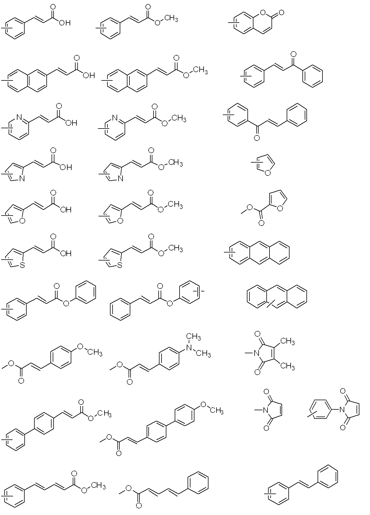
〔6〕前記光反応性の側鎖(B)が、前記式(b)で表され、R9が、ビニルフェニル基、-CH=CH2、-C(CH3)=CH2、又は下記のいずれかの基である、上記〔3〕~〔5〕のいずれかに記載の液晶表示素子の製造方法。
上記液晶配向層が対向するように配置された上記2枚の基板の間に液晶層を挟持した液晶セルと、
液晶層に電圧を印加しながら紫外線を照射する手段と、
を有することを特徴とする垂直配向方式の液晶表示素子。
〔8〕液晶を垂直に配向させる側鎖(A)及び光反応性の側鎖(B)を有するポリアミック酸及びそれをイミド化させて得られるポリイミドからなる群から選ばれる少なくとも一種を含有する液晶配向剤。
〔9〕液晶を垂直に配向させる側鎖(A)を有するジアミン及び光反応性の側鎖(B)を有するジアミンを含むジアミン成分とテトラカルボン酸二無水物とを反応させて得られるポリアミック酸及びそれをイミド化させて得られるポリイミドからなる群から選ばれる少なくとも一種を含有する液晶配向剤であり、上記光反応性の側鎖(B)を有するジアミンが、下記式(2)で表されることを特徴とする液晶配向剤。

置換基:-O-、-COO-、-NHCO-、-NH-、炭素環基、又は複素環基。
R8は-CH2-、-O-、-COO-、-OCO-、-NHCO-、-NH-、-N(CH3)-、-CON(CH3)-、又は-N(CH3)CO-を表し、R11はビニルフェニル基、-CH=CH2、-C(CH3)=CH2、又は下記のいずれかの基を表す。)

〔11〕前記液晶を垂直に配向させる側鎖(A)を有するジアミンが、前記式(1)で表され、l、m及びnがいずれも1であって、R2がフェニレンであり、R3がフェニレン又はシクロヘキシレンであり、R4がシクロヘキシレンであり、R5が炭素原子数2~24のアルキル基であるか、又はl、m及びnがいずれも0である場合、R5が炭素原子数12~22のアルキル基であるジアミンである、上記〔10〕に記載の液晶配向剤。
〔12〕前記液晶を垂直に配向させる側鎖(A)を有するジアミンが、下記のいずれかの構造を有するジアミンである、上記〔8〕~〔11〕のいずれかに記載の液晶配向剤。
〔13〕上記〔8〕~〔12〕のいずれかに記載の液晶配向剤を用いて得られる液晶配向膜。
また、本発明の液晶配向剤は、液晶分子に電圧を印加しながら紫外線を照射することで作製される垂直配向方式の液晶表示素子に用いることにより、液晶組成物中や液晶配向膜中に光重合性化合物を添加しなくても、液晶の応答速度が速められた(応答時間が短かい)液晶表示素子を得ることができる。
液晶を垂直に配向させる側鎖(側鎖Aともいう)とは、液晶分子を基板に対して垂直に配向させる能力を有する側鎖であり、この能力を有していればその構造は限定されない。側鎖Aとしては、例えば、長鎖のアルキル基、長鎖のフルオロアルキル基、末端にアルキル基やフルオロアルキル基を有する環状基、ステロイド基などが知られており、本発明においても好適に用いられる。これらの基は、上記の能力を有している限りにおいて、ポリアミック酸又はポリイミドの主鎖に直接結合していてもよく、適当な結合基を介して結合していてもよい。
上記の側鎖Aとしては、下記式(a)で表されるものが例示できる。
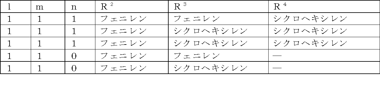
また、l、m、及びnがともに0である場合、R5の構造として好ましくは、炭素原子数12~22、好ましくは12~20のアルキル基若しくはフッ素含有アルキル基、芳香環、脂肪族環、複素環、又はそれらからなる大環状基であり、より好ましくは炭素原子数12~20、好ましくは12~18のアルキル基若しくはフッ素含有アルキル基である。
上記、光反応性の側鎖(側鎖Bともいう)は、紫外線の照射によって光反応を起こし、共有結合を形成し得る官能基を有する側鎖であり、この能力を有していればその構造は限定されない。側鎖Bとしては、例えば光反応性基として、ビニル基、アクリル基、メタクリル基、アントラセニル基、シンナモイル基、カルコニル基、クマリン基、マレイミド基、スチルベン基などを有する側鎖などが知られており、本発明においても好適に用いられる。これらの基は、上記の能力を有している限りにおいて、ポリアミック酸又はポリイミドの主鎖に直接結合していてもよく、適当な結合基を介して結合していてもよい。
上記側鎖Bとしては、下記式(b)で表されるものが例示できる。

置換基:-O-、-COO-、-NHCO-、-NH-、炭素環基、複素環基。
炭素環基、及び複素環基としては、具体的には以下のような構造が挙げられるが、これに限定されるものではない。

上記式(b)中のR9は、ビニルフェニル基、-CR10=CH2、炭素環基、複素環基、又は下記の式で表される基を表し、R10は水素原子又はフッ素原子で置換されていてもよいメチル基を表す。









本発明における、上記、側鎖Aと側鎖Bを有するポリアミック酸は、側鎖Aを有するジアミン及び/側鎖Bを有するジアミンとテトラカルボン酸二無水物との反応により、又はジアミンと、側鎖Aを有するテトラカルボン酸二無水物及び/又は側鎖Bを有するテトラカルボン酸二無水物との反応により、更には、側鎖Aを有するジアミン及び/側鎖Bを有するジアミンと側鎖Aを有するテトラカルボン酸二無水物及び/又は側鎖Bを有するテトラカルボン酸二無水物との反応により得ることが出来る。
このうち、原料合成の容易性などから、側鎖Aを有するジアミン及び/側鎖Bを有するジアミンとテトラカルボン酸二無水物との反応により得るのが好ましい。
側鎖Aを有するジアミン化合物(以下、ジアミンAとも言う)としては、ジアミン側鎖にアルキル基、フッ素含有アルキル基、芳香環、脂肪族環、複素環、又はそれらからなる大環状置換体を有するジアミンを例として挙げることが出来る。具体的には、前記式(a)で表される側鎖を有するジアミンを挙げることができる。より具体的には、例えば、下記式(1)、(3)、(4)、又は(5)で表されるジアミンを挙げることが出来るが、これに限定されるものではない。


式(1)の具体的な構造としては、下記の式[A-1]~式[A-24]で示されるジアミンを例示することができるが、これに限定されるものではない。


式[A-6]及び式[A-7]中、A2は、-O-、-OCH2-、-CH2O-、-COOCH2-、又は-CH2OCO-を示し、A3は炭素子数1~22のアルキル基、アルコキシ基、フッ素含有アルキル基又はフッ素含有アルコキシ基である。


式[A-11]及び式[A-12]中、A6は、-COO-、-OCO-、-CONH-、-NHCO-、-COOCH2-、-CH2OCO-、-CH2O-、-OCH2-、-CH2-、-O-、又は-NH-を表し、A7はフッ素基、シアノ基、トリフルオロメチル基、ニトロ基、アゾ基、ホルミル基、アセチル基、アセトキシ基、又は水酸基を表す。

式[A-13]及び式[A-14]中、A8は、炭素原子数3~12のアルキル基を表し、1,4-シクロヘキシレンのシス-トランス異性は、それぞれトランス異性体である。

式[A-15]及び式[A-16]中、A9は、炭素原子数3~12アルキル基を表し、1,4-シクロヘキシレンのシス-トランス異性は、それぞれトランス異性体である。

上記のジアミン化合物は、液晶配向膜とした際の液晶配向性、プレチルト角、電圧保持特性、蓄積電荷などの特性に応じて、1種類又は2種類以上を混合して使用することもできる。
側鎖Bを有するジアミン化合物(ジアミンBとも言う。)としては、ジアミン側鎖にビニル基、アクリル基、メタクリル基、アントラセニル基、シンナモイル基、カルコニル基、クマリン基、マレイミド基、スチルベン基などの光反応性基を有するジアミンを例として挙げることが出来る。具体的には、前記式(b)で表される側鎖を有するジアミンを挙げることができる。より具体的には例えば下記の一般式(2)で表されるジアミンを挙げることができるが、これに限定されるものではない。

置換基:-O-、-COO-、-NHCO-、-NH-、炭素環基、又は複素環基。
R8は-CH2-、-O-、-COO-、-OCO-、-NHCO-、-NH-、-N(CH3)-、-CON(CH3)-、又は-N(CH3)CO-を表し、R11はビニルフェニル基、-CH=CH2、-C(CH3)=CH2、又は下記のいずれかの基を表す。

具体的には、以下のような化合物が挙げられるが、これに限定されるものではない。


上記のジアミン化合物は、液晶配向膜とした際の液晶配向性、プレチルト角、電圧保持特性、蓄積電荷などの特性、液晶表示素子とした際の液晶の応答速度などに応じて、1種類又は2種類以上を混合して使用することもできる。
本発明に用いられるポリアミック酸は、本発明の効果を損わない限りにおいて、ジアミンA及びジアミンB以外のその他のジアミン化合物をジアミン成分として併用することができる。その具体例を以下に挙げる。
本発明に用いるポリアミック酸の合成において、上記のジアミン成分と反応させるテトラカルボン酸二無水物は特に限定されない。テトラカルボン酸二無水物を得るための原材料であるテトラカルボン酸の具体例を以下に挙げる。
ジアミン成分とテトラカルボン酸二無水物との反応により、ポリアミック酸を得るにあたっては、公知の合成手法を用いることができる。一般的には、ジアミン成分とテトラカルボン酸二無水物とを有機溶媒中で反応させる方法である。ジアミン成分とテトラカルボン酸二無水物との反応は、有機溶媒中で比較的容易に進行し、かつ副生成物が発生しない点で有利である。
以下に、有機溶媒の具体例を挙げる。
N,N-ジメチルホルムアミド、N,N-ジメチルアセトアミド、N,N-ジエチルホルムアミド、N-メチルホルムアミド、N-メチル-2-ピロリドン、N-エチル-2-ピロリドン、2-ピロリドン、1,3-ジメチル-2-イミダゾリジノン、3-メトキシ-N,N-ジメチルプロパンアミド、N-メチルカプロラクタム、ジメチルスルホキシド、テトラメチル尿素、ピリジン、ジメチルスルホン、ヘキサメチルスルホキシド、γ-ブチロラクトン、イソプロピルアルコール、メトキシメチルペンタノール、ジペンテン、エチルアミルケトン、メチルノニルケトン、メチルエチルケトン、メチルイソアミルケトン、メチルイソプロピルケトン、メチルセルソルブ、エチルセルソルブ、メチルセロソルブアセテート、ブチルセロソルブアセテート、エチルセロソルブアセテート、ブチルカルビトール、エチルカルビトール、エチレングリコール、エチレングリコールモノアセテート、エチレングリコールモノイソプロピルエーテル、エチレングリコールモノブチルエーテル、プロピレングリコール、プロピレングリコールモノアセテート、プロピレングリコールモノメチルエーテル、プロピレングリコールモノブチルエーテル、プロピレングリコール-tert-ブチルエーテル、ジプロピレングリコールモノメチルエーテル、プロピレングリコールモノメチルエーテルアセテート、ジエチレングリコール、ジエチレングリコールモノアセテート、ジエチレングリコールジメチルエーテル、ジエチレングリコールジエチルエーテル、ジプロピレングリコールモノアセテートモノメチルエーテル、ジプロピレングリコールモノメチルエーテル、ジプロピレングリコールモノエチルエーテル、ジプロピレングリコールモノアセテートモノエチルエーテル、ジプロピレングリコールモノプロピルエーテル、ジプロピレングリコールモノアセテートモノプロピルエーテル、3-メチル-3-メトキシブチルアセテート、トリプロピレングリコールメチルエーテル、3-メチル-3-メトキシブタノール、ジイソプロピルエーテル、エチルイソブチルエーテル、ジイソブチレン、アミルアセテート、ブチルブチレート、ブチルエーテル、ジイソブチルケトン、メチルシクロへキセン、プロピルエーテル、ジヘキシルエーテル、ジオキサン、n-へキサン、n-ペンタン、n-オクタン、ジエチルエーテル、シクロヘキサノン、エチレンカーボネート、プロピレンカーボネート、乳酸メチル、乳酸エチル、酢酸メチル、酢酸エチル、酢酸n-ブチル、酢酸プロピレングリコールモノエチルエーテル、ピルビン酸メチル、ピルビン酸エチル、3-メトキシプロピオン酸メチル、3-エトキシプロピオン酸メチルエチル、3-メトキシプロピオン酸エチル、3-エトキシプロピオン酸、3-メトキシプロピオン酸、3-メトキシプロピオン酸プロピル、3-メトキシプロピオン酸ブチル、ジグライム、4-ヒドロキシ-4-メチル-2-ペンタノン、2-エチル-1-ヘキサノール。これらの有機溶媒は単独で使用しても、混合して使用してもよい。
上記したポリアミック酸をイミド化させてポリイミドとする方法としては、ポリアミック酸の溶液をそのまま加熱する熱イミド化、ポリアミック酸の溶液に触媒を添加する触媒イミド化が挙げられる。
本発明に用いるポリイミドにおいて、ポリアミック酸からポリイミドへのイミド化率は、必ずしも100%である必要はない。
液晶配向剤は、液晶配向膜を形成するための塗布液であり、液晶配向膜を形成するための樹脂成分が有機溶媒に溶解した溶液である。ここで、前記の樹脂成分は、上記したポリアミック酸及びポリイミドからなる群から選ばれる少なくとも一種の重合体を含む樹脂成分である。その際、樹脂成分の含有量は1質量%~20質量%が好ましく、より好ましくは3質量%~15質量%、特に好ましくは3~10質量%である。
また、以下に示すような溶媒は、塗膜の均一性や平滑性を向上させるので、樹脂成分の溶解性が高い溶媒に混合して使用すると好ましい。例えば、イソプロピルアルコール、メトキシメチルペンタノール、メチルセロソルブ、エチルセロソルブ、ブチルセロソルブ、メチルセロソルブアセテート、ブチルセロソルブアセテート、エチルセロソルブアセテート、ブチルカルビトール、エチルカルビトール、エチルカルビトールアセテート、エチレングリコール、エチレングリコールモノアセテート、エチレングリコールモノイソプロピルエーテル、エチレングリコールモノブチルエーテル、プロピレングリコール、プロピレングリコールモノアセテート、プロピレングリコールモノメチルエーテル、プロピレングリコールモノブチルエーテル、プロピレングリコール-tert-ブチルエーテル、ジプロピレングリコールモノメチルエーテル、ジエチレングリコール、ジエチレングリコールモノアセテート、ジエチレングリコールジメチルエーテル、ジエチレングリコールジエチルエーテル、ジプロピレングリコールモノアセテートモノメチルエーテル、ジプロピレングリコールモノメチルエーテル、プロピレングリコールモノメチルエーテルアセテート、ジプロピレングリコールモノエチルエーテル、ジプロピレングリコールモノアセテートモノエチルエーテル、ジプロピレングリコールモノプロピルエーテル、ジプロピレングリコールモノアセテートモノプロピルエーテル、3-メチル-3-メトキシブチルアセテート、トリプロピレングリコールメチルエーテル、3-メチル-3-メトキシブタノール、ジイソプロピルエーテル、エチルイソブチルエーテル、ジイソブチレン、アミルアセテート、ブチルブチレート、ブチルエーテル、ジイソブチルケトン、メチルシクロへキセン、プロピルエーテル、ジヘキシルエーテル、n-へキサン、n-ペンタン、n-オクタン、ジエチルエーテル、乳酸メチル、乳酸エチル、酢酸メチル、酢酸エチル、酢酸n-ブチル、酢酸プロピレングリコールモノエチルエーテル、ピルビン酸メチル、ピルビン酸エチル、3-メトキシプロピオン酸メチル、3-エトキシプロピオン酸メチルエチル、3-メトキシプロピオン酸エチル、3-エトキシプロピオン酸、3-メトキシプロピオン酸、3-メトキシプロピオン酸プロピル、3-メトキシプロピオン酸ブチル、1-メトキシ-2-プロパノール、1-エトキシ-2-プロパノール、1-ブトキシ-2-プロパノール、1-フェノキシ-2-プロパノール、プロピレングリコールモノアセテート、プロピレングリコールジアセテート、プロピレングリコール-1-モノメチルエーテル-2-アセテート、プロピレングリコール-1-モノエチルエーテル-2-アセテート、ジプロピレングリコール、2-(2-エトキシプロポキシ)プロパノール、乳酸メチルエステル、乳酸エチルエステル、乳酸n-プロピルエステル、乳酸n-ブチルエステル、乳酸イソアミルエステル、2-エチル-1-ヘキサノールなどが挙げられる。これらの溶媒は複数種類を混合してもよい。これらの溶媒を用いる場合は、液晶配向剤に含まれる溶媒全体の5~80質量%であることが好ましく、より好ましくは20~60質量%である。
また本発明の液晶配向剤を用いて得られる液晶配向膜のラビング耐性をさらに上げるために、2,2'-ビス(4-ヒドロキシ-3,5-ジヒドロキシメチルフェニル)プロパン、テトラ(メトキシメチル)ビスフェノール等のフェノール化合物を添加してもよい。これらの化合物を使用する場合は、液晶配向剤に含有される樹脂成分の100質量部に対して0.1~30質量部であることが好ましく、より好ましくは1~20質量部である。
本発明に用いられる液晶配向剤には、上記の他、本発明の効果が損なわれない範囲であれば、液晶配向膜の誘電率や導電性などの電気特性を変化させる目的の誘電体や導電物質を添加してもよい。
本発明の液晶配向剤は、本発明の液晶表示素子を作製する為の液晶配向剤として有用なだけでなく、ラビング処理や光配向処理によって作製される液晶配向膜の用途でも好適に使用できる。
本発明の液晶配向剤は、基板上に塗布、焼成した後、ラビング処理や光照射などで配向処理をして、又は垂直配向用途などでは配向処理無し、で液晶配向膜として用いることができる。この際、用いる基板としては透明性の高い基板であれば特に限定されず、ガラス基板、アクリル基板やポリカーボネート基板などのプラスチック基板などを用いることができる。また、液晶駆動のためのITO電極などが形成された基板を用いることがプロセスの簡素化の観点から好ましい。また、反射型の液晶表示素子では片側の基板のみにならばシリコンウエハー等の不透明な物でも使用でき、この場合の電極はアルミニウム等の光を反射する材料も使用できる。
焼成後の被膜の厚みは特に限定されないが、好ましくは5~300nm、より好ましくは10~100nmである。
液晶を水平配向や傾斜配向させる場合は、焼成後の塗膜をラビング又は偏光紫外線照射などで処理される。
本発明の液晶表示素子は、液晶を垂直に配向させる側鎖(A)、及び光反応性の側鎖(B)を有するポリアミック酸及びそれをイミド化させて得られるポリイミドからなる群から選ばれる少なくとも一種を含有する液晶配向剤から形成された液晶配向層を有する2枚の基板と、
上記液晶配向層が対向するように配置された上記2枚の基板の間に液晶層を挟持した液晶セルと、
液晶層に電圧を印加しながら紫外線を照射する手段と、
を有することを特徴とする。
また、TFT型の素子のような高機能素子においては、液晶駆動のための電極と基板の間にトランジスタの如き素子が形成されたものが用いられる。
透過型の液晶素子の場合は、上記の如き基板を用いることが一般的であるが、反射型の液晶表示素子では、片側の基板のみにならばシリコンウエハー等の不透明な基板も用いることが可能である。その際、基板に形成された電極には、光を反射するアルミニウムの如き材料を用いることもできる。
[ポリアミック酸の合成]
以下に使用したテトラカルボン酸二無水物などの化合物の略号を示した。
(テトラカルボン酸二無水物)
C-1:1,2,3,4-シクロブタンテトラカルボン酸二無水物
(ジアミン化合物)
DA-6:p-フェニレンジアミン
DA-7:1,3-ジアミノ-4-オクタデシルオキシベンゼン
DA-8:1,3-ジアミノ-4-〔4-(トランス-4-n-ヘプチルシクロへキシル)フェノキシ〕ベンゼン
DA-9:1,3-ジアミノ-4-{4-〔トランス-4-(トランス-4-n-ペンチルシクロへキシル)シクロへキシル〕フェノキシ}ベンゼン

NMP:N-メチル-2-ピロリドン
BCS:ブチルセロソルブ
なお、上記のジアミン化合物のうち、DA-2及びDA-3は以下に記す参考合成例のようにして得られたものを使用した。
500mL(ミリリットル)三口フラスコに、テトラメチレングリコールモノビニルエーテル5.94g、トリエチルアミン5.70g、及びトルエン30mLを加えた。系内を100℃に加熱し、20mLのトルエンに溶解させた2,4-ジニトロフルオロベンゼン10gを滴下し、100℃で6時間攪拌した。反応終了後、純水50mLを加え、攪拌した後、酢酸エチルを加えて有機層を抽出した。有機層に無水硫酸マグネシウムを加えて脱水乾燥し、濾過した後に、ロータリーエバポレーターを用いて溶媒留去を行った。残渣を酢酸エチル/ヘキサン=7/3(容積比、以下同様である。)の混合溶媒を用いて再結晶を行い、13.2gの2,4-ジニトロ-1-(4-ビニルオキシ)ブトキシベンゼンを得た(収率90%)。
1H NMR (400 MHz,CDCl3):δ=6.60-6.62 (d,1H), 6.44-6.51 (m,1H), 6.13-6.14 (d,1H), 6.03-6.07 (m,1H), 4.14-4.21 (d,1H), 3.96-4.00 (d,1H),3.92-3.96 (t,2H),3.73-3.73 (m,4H),3.34 (s,2H)1.85-1.87 (m,4H)
300mL三口フラスコに、10-ウンデセン-1-オール5.11g、ピリジン2.37g、及びテトラヒドロフラン100mLを加えた。系内を氷冷により0℃にし、3,5-ジニトロベンゾイルクロリドを8.3g加え、室温で2時間攪拌した。反応終了後、純水20mLを加え、攪拌した後、酢酸エチルを加えて有機層を抽出した。有機層に無水硫酸マグネシウムを加えて脱水乾燥し、濾過した後に、ロータリーエバポレーターを用いて溶媒留去を行った。残渣を酢酸エチル/ヘキサン=7/3の混合溶媒を用いて再結晶を行い、6.9gのウンデセ-10-エニル-3,5-ジニトロベンゾエートを得た(収率63%)。
1H NMR (400 MHz,[D6]-DMSO):δ=6.41 (s,2H), 6.01 (s,1H), 5.73-5.84 (m,1H), 4.91-5.01 (m,6H), 4.13-4.16 (t,2H), 1.98-2.02 (m,2H), 1.60-1.67 (m,2H), 1.27-1.37 (m,12H)
以下の合成例におけるポリアミック酸の分子量は、昭和電工社製の常温ゲル浸透クロマトグラフィー(GPC)装置(GPC-101)、Shodex社製のカラム(KD-803、KD-805)を用い、以下のようにして測定した。
カラム温度:50℃
溶離液:N,N’-ジメチルホルムアミド(添加剤として、臭化リチウム-水和物(LiBr・H2O)が30mmol/L、リン酸・無水結晶(o-リン酸)が30mmol/L、テトラヒドロフラン(THF)が10ml/L)
流速:1.0ml/分
検量線作成用標準サンプル:東ソー社製 TSK 標準ポリエチレンオキサイド(分子量 約900,000、150,000、100,000、30,000)、及びポリマーラボラトリー社製 ポリエチレングリコール(分子量 約12,000、4,000、1,000)。
テトラカルボン酸二無水物として、C-1を0.78g(3.96mmol)、ジアミン成分として、DA1を0.85g(3.20mmol)及びDA-7を0.30g(0.80mmol)用い、NMP7.69g中、室温で16時間反応させポリアミック酸(PAA-1)の濃度が20質量%の溶液を得た。このポリアミック酸溶液(PAA-1)8.0gをNMP12.0g、及びBCS5.3gを用いて希釈し、ポリアミック酸(PAA-1)が6質量%、NMPが74質量%、及びBCSが20質量%の液晶配向剤(A1)を得た。なお、PAA-1の数平均分子量は20,500、及び重量平均分子量は63,000であった。
テトラカルボン酸二無水物として、C-1を0.78g(3.96mmol)、ジアミン成分として、DA1を0.95g(3.60mmol)及びDA-7を0.15g(0.40mmol)用い、NMP7.51g中、室温で16時間反応させポリアミック酸(PAA-2)の濃度が20質量%の溶液を得た。このポリアミック酸溶液(PAA-2)8.0gをNMP12.2g、及びBCS5.3gを用いて希釈し、ポリアミック酸(PAA-2)が6質量%、NMPが74質量%、及びBCSが20質量%の液晶配向剤(A2)を得た。なお、PAA-2の数平均分子量は25,200、及び重量平均分子量は86,400であった。
テトラカルボン酸二無水物として、C-1を0.49g(2.48mmol)、ジアミン成分として、DA1を0.59g(2.25mmol)及びDA-8を0.095g(0.25mmol)用い、NMP4.70g中、室温で16時間反応させポリアミック酸(PAA-3)の濃度が20質量%の溶液を得た。このポリアミック酸溶液(PAA-3)4.7gをNMP7.8g、及びBCS3.1gを用いて希釈し、ポリアミック酸(PAA-3)が6質量%、NMPが74質量%、及びBCSが20質量%の液晶配向剤(A3)を得た。なお、PAA-3の数平均分子量は20,400、及び重量平均分子量は57,800であった。
テトラカルボン酸二無水物として、C-1を0.49g(2.48mmol)、ジアミン成分として、DA1を0.59g(2.25mmol)及びDA-9を0.11g(0.25mmol)用い、NMP4.75g中、室温で16時間反応させポリアミック酸(PAA-4)の濃度が20質量%の溶液を得た。このポリアミック酸溶液(PAA-4)4.7gをNMP7.9g、及びBCS3.2gを用いて希釈し、ポリアミック酸(PAA-4)が6質量%、NMPが74質量%、及びBCSが20質量%の液晶配向剤(A4)を得た。なお、PAA-4の数平均分子量は19,100、及び重量平均分子量は55,000であった。
テトラカルボン酸二無水物として、C-1を0.47g(2.40mmol)、ジアミン成分として、DA2を0.39g(1.75mmol)及びDA-7を0.28g(0.75mmol)用い、NMP4.57g中、室温で16時間反応させポリアミック酸(PAA-5)の濃度が20質量%の溶液を得た。このポリアミック酸溶液(PAA-5)4.5gをNMP7.6g、及びBCS3.0gを用いて希釈し、ポリアミック酸(PAA-5)が6質量%、NMPが74質量%、及びBCSが20質量%の液晶配向剤(A5)を得た。なお、PAA-5の数平均分子量は16,700、及び重量平均分子量は52,900であった。
テトラカルボン酸二無水物として、C-1を0.47g(2.40mmol)、ジアミン成分として、DA2を0.44g(2.00mmol)及びDA-7を0.19g(0.50mmol)用い、NMP4.41g中、室温で16時間反応させポリアミック酸(PAA-6)の濃度20が質量%の溶液を得た。このポリアミック酸溶液(PAA-6)4.4gをNMP7.3g、及びBCS2.9gを用いて希釈し、ポリアミック酸(PAA-6)が6質量%、NMPが74質量%、及びBCSが20質量%の液晶配向剤(A6)を得た。なお、PAA-6の数平均分子量は24,400、及び重量平均分子量は93,500であった。
テトラカルボン酸二無水物として、C-1を0.49g(2.48mmol)、ジアミン成分として、DA3を0.53g(1.75mmol)及びDA-7を0.28g(0.75mmol)用い、NMP5.20g中、室温で16時間反応させポリアミック酸(PAA-7)の濃度が20質量%の溶液を得た。このポリアミック酸溶液(PAA-7)5.4gをNMP9.0g、及びBCS3.6gを用いて希釈し、ポリアミック酸(PAA-7)が6質量%、NMPが74質量%、及びBCSが20質量%の液晶配向剤(A7)を得た。なお、PAA-7の数平均分子量は20,900、及び重量平均分子量は78,900であった。
テトラカルボン酸二無水物として、C-1を0.49g(2.48mmol)、ジアミン成分として、DA3を0.61g(2.00mmol)及びDA-7を0.19g(0.50mmol)用い、NMP5.13g中、室温で16時間反応させポリアミック酸(PAA-8)の濃度が20質量%の溶液を得た。このポリアミック酸溶液(PAA-8)5.3gをNMP8.8g、及びBCS3.5gを用いて希釈し、ポリアミック酸(PAA-8)が6質量%、NMPが74質量%、及びBCSが20質量%の液晶配向剤(A8)を得た。なお、PAA-8の数平均分子量は18,800、及び重量平均分子量は67,300であった。
テトラカルボン酸二無水物として、C-1を0.49g(2.48mmol)、ジアミン成分として、DA4を0.46g(2.00mmol)及びDA-7を0.19g(0.50mmol)用い、NMP4.55g中、室温で16時間反応させポリアミック酸(PAA-9)の濃度が20質量%の溶液を得た。このポリアミック酸溶液(PAA-9)4.5gをNMP6.5g、及びBCS3.0gを用いて希釈し、ポリアミック酸(PAA-9)が6質量%、NMPが74質量%、及びBCSが20質量%の液晶配向剤(A9)を得た。なお、PAA-9の数平均分子量は17,600、及び重量平均分子量は47,100であった。
テトラカルボン酸二無水物として、C-1を0.49g(2.48mmol)、ジアミン成分として、DA4を0.52g(2.25mmol)及びDA-7を0.09g(0.25mmol)用い、NMP4.41g中、室温で16時間反応させポリアミック酸(PAA-10)の濃度が20質量%の溶液を得た。このポリアミック酸溶液(PAA-10)4.3gをNMP6.1g、及びBCS2.8gを用いて希釈し、ポリアミック酸(PAA-10)が6質量%、NMPが74質量%、及びBCSが20質量%の液晶配向剤(A10)を得た。なお、PAA-10の数平均分子量は19,500、及び重量平均分子量は55,500であった。
テトラカルボン酸二無水物として、C-1を0.49g(2.48mmol)、ジアミン成分として、DA5を0.82g(2.00mmol)及びDA-7を0.19g(0.50mmol)用い、NMP5.99g中、室温で16時間反応させポリアミック酸(PAA-11)の濃度が20質量%の溶液を得た。このポリアミック酸溶液(PAA-11)5.0gをNMP6.3g、及びBCS3.3gを用いて希釈し、ポリアミック酸(PAA-11)が6質量%、NMPが74質量%、及びBCSが20質量%の液晶配向剤(A11)を得た。なお、PAA-11の数平均分子量は17,000、及び重量平均分子量は56,000であった。
テトラカルボン酸二無水物として、C-1を0.49g(2.48mmol)、ジアミン成分として、DA5を0.93g(2.25mmol)及びDA-7を0.19g(0.25mmol)用い、NMP6.03g中、室温で16時間反応させポリアミック酸(PAA-12)の濃度が20質量%の溶液を得た。このポリアミック酸溶液(PAA-12)5.0gをNMP6.3g、及びBCS3.3gを用いて希釈し、ポリアミック酸(PAA-12)が6質量%、NMPが74質量%、及びBCSが20質量%の液晶配向剤(A12)を得た。なお、PAA-12の数平均分子量は19,500、及び重量平均分子量は59,000であった。
テトラカルボン酸二無水物として、C-1を0.49g(2.48mmol)、ジアミン成分として、DA-10を0.64g(2.00mmol)及びDA-7を0.19g(0.50mmol)用い、NMP5.26g中、室温で16時間反応させポリアミック酸(PAA-14)の濃度が20質量%の溶液を得た。このポリアミック酸溶液(PAA-14)5.0gをNMP6.3g、及びBCS3.3gを用いて希釈し、ポリアミック酸(PAA-14)が6質量%、NMPが74質量%、及びBCSが20質量%の液晶配向剤(A13)を得た。なお、PAA-14の数平均分子量は17,500、及び重量平均分子量は57,000であった。
テトラカルボン酸二無水物として、C-1を0.49g(2.48mmol)、ジアミン成分として、DA-10を0.72g(2.25mmol)及びDA-7を0.09g(0.25mmol)用い、NMP5.20g中、室温で16時間反応させポリアミック酸(PAA-15)の濃度が20質量%の溶液を得た。このポリアミック酸溶液(PAA-15)5.0gをNMP6.3g、及びBCS3.3gを用いて希釈し、ポリアミック酸(PAA-15)が6質量%、NMPが74質量%、及びBCSが20質量%の液晶配向剤(A14)を得た。なお、PAA-15の数平均分子量は18,500、及び重量平均分子量は59,000であった。
テトラカルボン酸二無水物として、C-1を1.30g(6.65mmol)、ジアミン成分として、DA-6を0.68g(6.30mmol)及びDA-7を0.26g(0.7mmol)用い、NMP12.74g中、室温で16時間反応させポリアミック酸(PAA-13)の濃度が20質量%の溶液を得た。このポリアミック酸溶液(PAA-13)10.0gをNMP16.7g、及びBCS6.7gを用いて希釈し、ポリアミック酸(PAA-13)が6質量%、NMPが74質量%、及びBCSが20質量%の液晶配向剤(A15)を得た。なお、PAA-13の数平均分子量は18,700、及び重量平均分子量は58,000であった。
合成例1で得られた液晶配向剤[A1]を、画素サイズが100×300ミクロンで、ライン/スペースがそれぞれ5ミクロンのITO電極パターンが形成されているITO電極基板のITO面にスピンコートした。80℃のホットプレートで90秒間乾燥した後、160℃の熱風循環式オーブンで60分間焼成を行い、膜厚100nmの液晶配向膜を形成した。
また、合成例1で得られた液晶配向剤[A1]を、電極パターンが形成されていないITO面にスピンコートし、80℃のホットプレートで90秒間乾燥した後、160℃の熱風循環式オーブンで60分間焼成を行い、膜厚100nmの液晶配向膜を形成した。これらの2枚の基板を用意し、一方の基板の液晶配向膜面上に6μmのビーズスペーサーを散布した後、その上からシール剤を印刷した。他方の基板を液晶配向膜面を内側にし、張り合わせた後、シール剤を硬化させて空セルを作製した。この空セルに液晶MLC-6608(メルク社製商品名)を減圧注入法によって注入し、液晶セルを作製した。
液晶配向剤[A1]を、表2に示すように、それぞれ、合成例2~14で得られた液晶配向剤[A2]~[A14]、及び比較合成例1で得られた液晶配向剤[A15]に変更した以外は、実施例1と同様にして液晶セルを作製し、応答速度を測定した。その結果を表2に示した。
電圧を印加していない液晶セルに、電圧±4V、周波数1kHzの矩形波を印加した際の、液晶パネルの輝度の時間変化をオシロスコープにて取り込んだ。電圧を印加していない時の輝度を0%、±4Vの電圧を印加し、飽和した輝度の値を100%として、輝度が10%~90%まで変化する時間を立上がりの応答速度とした。

また、上記と同様に実施例13,14においても、チルト発現側鎖の導入量が少ない方がUV照射後に応答速度の向上度合いが大きかった。また、実施例1, 13と実施例2,14では、チルト発現側鎖の導入量が同じであって、光反応性基が同じであってもアルキルスペーサーが長いDA-10を用いた場合はDA-1を用いた場合と比較して、UV照射後の応答速度の向上度合いが大きかった。
また、本発明の液晶配向剤は、液晶分子に電圧を印加しながら紫外線を照射することで作製される垂直配向方式の液晶表示素子を作製するのに利用できる他、このような工程を含まないで製造される液晶表示素子にも利用できる。
なお、2010年2月26日に出願された日本特許出願2010-043372号の明細書、特許請求の範囲、及び要約書の全内容をここに引用し、本発明の明細書の開示として、取り入れるものである。
Claims (13)
- 液晶を垂直に配向させる側鎖(A)及び光反応性の側鎖(B)を有するポリアミック酸及びそれをイミド化させて得られるポリイミドからなる群から選ばれる少なくとも一種を含有する液晶配向剤を2枚の基板上に塗布して液晶配向層を形成し、
上記液晶配向層が対向するように2枚の基板を配置し、
上記2枚の基板の間に液晶層を挟持し、
液晶層に電圧を印加しながら紫外線を照射することを特徴とする垂直配向方式の液晶表示素子の製造方法。 - 前記液晶配向剤が、下記のポリアミック酸及びそれをイミド化させて得られるポリイミドのうちの少なくとも一種を含有する液晶配向剤である、請求項1に記載の液晶表示素子の製造方法。
液晶を垂直に配向させる側鎖(A)を有するジアミン及び光反応性の側鎖(B)を有するジアミンを含む
ジアミン成分とテトラカルボン酸二無水物とを反応させて得られるポリアミック酸。 - 前記液晶を垂直に配向させる側鎖(A)が、下記式(a)で表される、請求項1又は2に記載の液晶表示素子の製造方法。

- 前記光反応性の側鎖(B)が、下記式(b)で表される、請求項1~3のいずれかに記載の液晶表示素子の製造方法。

置換基:-O-、-COO-、-NHCO-、-NH-、炭素環基、又は複素環基。
R8は-CH2-、-O-、-COO-、-OCO-、-NHCO-、-NH-、-N(CH3)-、-CON(CH3)-、-N(CH3)CO-、炭素環基、又は複素環基を表し、R9はビニルフェニル基、-CR10=CH2基、炭素環基、複素環基、又は以下の式で表される基を表し、R10は水素原子又はフッ素原子で置換されていてもよいメチル基を表す。)
- 前記液晶を垂直に配向させる側鎖(A)が、前記式(a)で表され、l、m及びnがいずれも1であって、R2がフェニレンであり、R3がフェニレン又はシクロヘキシレンであり、R4がシクロヘキシレンであり、R5が炭素原子数2~24のアルキル基であるか、又はl、m及びnがいずれも0である場合、R5が炭素原子数12~22のアルキル基である、請求項2~5のいずれかに記載の液晶表示素子の製造方法。
- 前記光反応性の側鎖(B)が、前記式(b)で表され、R9が、ビニルフェニル基、-CH=CH2、-C(CH3)=CH2、又は下記のいずれかの基である、請求項3~5のいずれかに記載の液晶表示素子の製造方法。
- 液晶を垂直に配向させる側鎖(A)及び光反応性の側鎖(B)を有するポリアミック酸、及びそれをイミド化させて得られるポリイミドからなる群から選ばれる少なくとも一種を含有する液晶配向剤から形成された液晶配向層を有する2枚の基板と、
上記液晶配向層が対向するように配置された上記2枚の基板の間に液晶層を挟持した液晶セルと、
液晶層に電圧を印加しながら紫外線を照射する手段と、
を有することを特徴とする垂直配向方式の液晶表示素子。 - 液晶を垂直に配向させる側鎖(A)及び光反応性の側鎖(B)を有するポリアミック酸及びそれをイミド化させて得られるポリイミドからなる群から選ばれる少なくとも一種を含有する液晶配向剤。
- 液晶を垂直に配向させる側鎖(A)を有するジアミン及び光反応性の側鎖(B)を有するジアミンを含むジアミン成分とテトラカルボン酸二無水物とを反応させて得られるポリアミック酸及びそれをイミド化させて得られるポリイミドからなる群から選ばれる少なくとも一種を含有する液晶配向剤であり、上記光反応性の側鎖(B)を有するジアミンが、下記式(2)で表されることを特徴とする液晶配向剤。
置換基:-O-、-COO-、-NHCO-、-NH-、炭素環基、又は複素環基。
R8は-CH2-、-O-、-COO-、-OCO-、-NHCO-、-NH-、-N(CH3)-、-CON(CH3)-、又は-N(CH3)CO-を表し、R11は、ビニルフェニル基、-CH=CH2、-C(CH3)=CH2、又は下記のいずれかの基を表す。)
- 前記液晶を垂直に配向させる側鎖(A)を有するジアミンが、下記式(1)で表される、請求項7~9のいずれかに記載の液晶配向剤。

- 前記液晶を垂直に配向させる側鎖(A)を有するジアミンが、前記式(1)で表され、l、m及びnがいずれも1であって、R2がフェニレンであり、R3がフェニレン又はシクロヘキシレンであり、R4がシクロヘキシレンであり、R5が炭素原子数2~24のアルキル基であるか、又はl、m及びnがいずれも0である場合、R5が炭素原子数12~22のアルキル基であるジアミンである、請求項10に記載の液晶配向剤。
- 前記液晶を垂直に配向させる側鎖(A)を有するジアミンが、下記のいずれかの構造を有するジアミンである、請求項8~11のいずれかに記載の液晶配向剤。

- 請求項8~12のいずれかに記載の液晶配向剤を用いて得られる液晶配向膜。
Priority Applications (5)
| Application Number | Priority Date | Filing Date | Title |
|---|---|---|---|
| KR1020127024919A KR101385331B1 (ko) | 2010-02-26 | 2011-02-25 | 액정 표시 소자 및 액정 배향제 |
| KR1020137011022A KR101831011B1 (ko) | 2010-02-26 | 2011-02-25 | 액정 표시 소자 및 액정 배향제 |
| JP2012501894A JP5257548B2 (ja) | 2010-02-26 | 2011-02-25 | 液晶表示素子および液晶配向剤 |
| CN201180020866.3A CN102859427B (zh) | 2010-02-26 | 2011-02-25 | 液晶显示元件和液晶取向剂 |
| KR1020137011024A KR101688687B1 (ko) | 2010-02-26 | 2011-02-25 | 액정 배향제 |
Applications Claiming Priority (2)
| Application Number | Priority Date | Filing Date | Title |
|---|---|---|---|
| JP2010-043372 | 2010-02-26 | ||
| JP2010043372 | 2010-02-26 |
Publications (1)
| Publication Number | Publication Date |
|---|---|
| WO2011105575A1 true WO2011105575A1 (ja) | 2011-09-01 |
Family
ID=44506972
Family Applications (1)
| Application Number | Title | Priority Date | Filing Date |
|---|---|---|---|
| PCT/JP2011/054372 Ceased WO2011105575A1 (ja) | 2010-02-26 | 2011-02-25 | 液晶表示素子および液晶配向剤 |
Country Status (5)
| Country | Link |
|---|---|
| JP (4) | JP5257548B2 (ja) |
| KR (3) | KR101831011B1 (ja) |
| CN (1) | CN102859427B (ja) |
| TW (1) | TWI601757B (ja) |
| WO (1) | WO2011105575A1 (ja) |
Cited By (10)
| Publication number | Priority date | Publication date | Assignee | Title |
|---|---|---|---|---|
| JP2011186049A (ja) * | 2010-03-05 | 2011-09-22 | Jsr Corp | 液晶表示素子の製造方法 |
| JP2012159826A (ja) * | 2011-01-11 | 2012-08-23 | Jsr Corp | 液晶表示素子の製造方法、液晶表示素子及び液晶配向剤 |
| US20130063688A1 (en) * | 2011-09-09 | 2013-03-14 | Samsung Electronics Co., Ltd. | Liquid crystal display |
| WO2013035803A1 (ja) * | 2011-09-08 | 2013-03-14 | 日産化学工業株式会社 | 液晶配向処理剤、液晶配向膜及び液晶表示素子 |
| WO2013094734A1 (ja) * | 2011-12-22 | 2013-06-27 | 日産化学工業株式会社 | 横電界駆動用液晶表示素子の製造方法 |
| WO2013099937A1 (ja) * | 2011-12-28 | 2013-07-04 | 日産化学工業株式会社 | 液晶配向剤、液晶配向膜、液晶表示素子及び液晶表示素子の製造方法 |
| KR20140107509A (ko) * | 2011-12-21 | 2014-09-04 | 닛산 가가쿠 고교 가부시키 가이샤 | 액정 배향 처리제, 액정 배향막 및 그것을 사용한 액정 표시 소자 그리고 화합물 |
| KR20140108571A (ko) * | 2011-12-28 | 2014-09-11 | 닛산 가가쿠 고교 가부시키 가이샤 | 액정 배향제, 액정 배향막, 액정 표시 소자 및 디아민 화합물 |
| JP2019040216A (ja) * | 2013-09-03 | 2019-03-14 | 日産化学株式会社 | 液晶配向剤、液晶配向膜及び液晶表示素子 |
| WO2023022155A1 (ja) * | 2021-08-19 | 2023-02-23 | 日産化学株式会社 | 高分子分散型液晶素子およびその製造方法 |
Families Citing this family (12)
| Publication number | Priority date | Publication date | Assignee | Title |
|---|---|---|---|---|
| JP5904120B2 (ja) | 2010-06-30 | 2016-04-13 | 日産化学工業株式会社 | 液晶配向剤、液晶配向膜、及び液晶表示素子 |
| WO2014208609A1 (ja) * | 2013-06-25 | 2014-12-31 | 日産化学工業株式会社 | 液晶配向剤、液晶配向膜、液晶表示素子 |
| TWI477479B (zh) * | 2013-07-18 | 2015-03-21 | Daxin Materials Corp | 二胺苯化合物、聚合物、配向膜用組成物、配向膜以及液晶顯示元件 |
| CN105814478B (zh) * | 2013-10-07 | 2019-09-17 | 日产化学工业株式会社 | 液晶取向剂、液晶取向膜和液晶表示元件 |
| CN104297981B (zh) * | 2014-10-31 | 2017-03-15 | 京东方科技集团股份有限公司 | 一种显示装置及其工作方法 |
| CN107003573A (zh) * | 2014-11-28 | 2017-08-01 | 夏普株式会社 | 液晶显示装置的制造方法 |
| JP6662306B2 (ja) * | 2015-02-06 | 2020-03-11 | 日産化学株式会社 | 液晶配向剤、液晶表示素子及び液晶表示素子の製造方法 |
| TWI781080B (zh) * | 2015-03-04 | 2022-10-21 | 日商日產化學工業股份有限公司 | 聚醯亞胺前驅物、及具有該前驅物之液晶配向劑、液晶配向膜及液晶顯示元件 |
| JP2017016005A (ja) | 2015-07-03 | 2017-01-19 | 株式会社ジャパンディスプレイ | 表示装置 |
| JPWO2017082387A1 (ja) * | 2015-11-12 | 2018-08-02 | 富士フイルム株式会社 | 液晶配向膜の製造方法、および三次元液晶セルの製造方法、ならびに三次元液晶セル |
| TWI632177B (zh) * | 2015-11-17 | 2018-08-11 | 奇美實業股份有限公司 | 液晶配向膜、液晶顯示元件以及其製造方法 |
| JP2017167412A (ja) | 2016-03-17 | 2017-09-21 | 株式会社ジャパンディスプレイ | 画像表示装置 |
Citations (6)
| Publication number | Priority date | Publication date | Assignee | Title |
|---|---|---|---|---|
| JPH04350822A (ja) * | 1991-05-29 | 1992-12-04 | Nec Corp | 液晶配向膜およびその製造方法および液晶光学素子 |
| JPH10170921A (ja) * | 1996-12-13 | 1998-06-26 | Matsushita Electric Ind Co Ltd | 液晶表示パネルの製造方法 |
| JPH11133430A (ja) * | 1997-10-27 | 1999-05-21 | Matsushita Electric Ind Co Ltd | 液晶配向膜及びその製造方法並びに液晶素子 |
| WO2008117615A1 (ja) * | 2007-03-26 | 2008-10-02 | Sharp Kabushiki Kaisha | 液晶表示装置及び配向膜材料用重合体 |
| JP2009139957A (ja) * | 2007-12-07 | 2009-06-25 | Cheil Industries Inc | 液晶光配向剤、これを含む液晶光配向膜、およびこれを含む液晶表示装置 |
| WO2010087280A1 (ja) * | 2009-01-30 | 2010-08-05 | ソニー株式会社 | 液晶表示装置及びその製造方法 |
Family Cites Families (7)
| Publication number | Priority date | Publication date | Assignee | Title |
|---|---|---|---|---|
| EP1021479B1 (en) * | 1997-09-25 | 2002-07-17 | Rolic AG | Photocrosslinkable polyimides |
| JP4331807B2 (ja) * | 1998-10-27 | 2009-09-16 | 三菱マテリアル株式会社 | 耐摩耗性に優れた硬質皮膜および硬質皮膜被覆部材 |
| JP3985261B2 (ja) | 2001-10-03 | 2007-10-03 | Jsr株式会社 | 液晶配向剤および液晶表示素子 |
| JP4175826B2 (ja) | 2002-04-16 | 2008-11-05 | シャープ株式会社 | 液晶表示装置 |
| JP5035517B2 (ja) * | 2007-02-16 | 2012-09-26 | 日産化学工業株式会社 | 液晶配向剤およびそれを用いた液晶表示素子 |
| US8163199B2 (en) * | 2008-06-30 | 2012-04-24 | Chimei Innoloux Corporation | Alignment treatment method of substrate for liquid crystal display device and manufacturing method thereof |
| TWI372922B (en) * | 2008-06-30 | 2012-09-21 | Chimei Innolux Corp | Manufacturing method of alignment film and manufacturing method of liquid crystal display panel |
-
2011
- 2011-02-25 JP JP2012501894A patent/JP5257548B2/ja active Active
- 2011-02-25 KR KR1020137011022A patent/KR101831011B1/ko active Active
- 2011-02-25 WO PCT/JP2011/054372 patent/WO2011105575A1/ja not_active Ceased
- 2011-02-25 KR KR1020127024919A patent/KR101385331B1/ko active Active
- 2011-02-25 TW TW100106409A patent/TWI601757B/zh active
- 2011-02-25 KR KR1020137011024A patent/KR101688687B1/ko active Active
- 2011-02-25 CN CN201180020866.3A patent/CN102859427B/zh active Active
-
2013
- 2013-02-26 JP JP2013036163A patent/JP5828329B2/ja active Active
- 2013-02-26 JP JP2013036152A patent/JP5321760B2/ja active Active
- 2013-05-24 JP JP2013110220A patent/JP5387793B2/ja active Active
Patent Citations (6)
| Publication number | Priority date | Publication date | Assignee | Title |
|---|---|---|---|---|
| JPH04350822A (ja) * | 1991-05-29 | 1992-12-04 | Nec Corp | 液晶配向膜およびその製造方法および液晶光学素子 |
| JPH10170921A (ja) * | 1996-12-13 | 1998-06-26 | Matsushita Electric Ind Co Ltd | 液晶表示パネルの製造方法 |
| JPH11133430A (ja) * | 1997-10-27 | 1999-05-21 | Matsushita Electric Ind Co Ltd | 液晶配向膜及びその製造方法並びに液晶素子 |
| WO2008117615A1 (ja) * | 2007-03-26 | 2008-10-02 | Sharp Kabushiki Kaisha | 液晶表示装置及び配向膜材料用重合体 |
| JP2009139957A (ja) * | 2007-12-07 | 2009-06-25 | Cheil Industries Inc | 液晶光配向剤、これを含む液晶光配向膜、およびこれを含む液晶表示装置 |
| WO2010087280A1 (ja) * | 2009-01-30 | 2010-08-05 | ソニー株式会社 | 液晶表示装置及びその製造方法 |
Cited By (25)
| Publication number | Priority date | Publication date | Assignee | Title |
|---|---|---|---|---|
| JP2011186049A (ja) * | 2010-03-05 | 2011-09-22 | Jsr Corp | 液晶表示素子の製造方法 |
| JP2012159826A (ja) * | 2011-01-11 | 2012-08-23 | Jsr Corp | 液晶表示素子の製造方法、液晶表示素子及び液晶配向剤 |
| JPWO2013035803A1 (ja) * | 2011-09-08 | 2015-03-23 | 日産化学工業株式会社 | 液晶配向処理剤、液晶配向膜及び液晶表示素子 |
| WO2013035803A1 (ja) * | 2011-09-08 | 2013-03-14 | 日産化学工業株式会社 | 液晶配向処理剤、液晶配向膜及び液晶表示素子 |
| KR101951501B1 (ko) * | 2011-09-08 | 2019-02-22 | 닛산 가가쿠 가부시키가이샤 | 액정 배향 처리제, 액정 배향막 및 액정 표시 소자 |
| TWI620794B (zh) * | 2011-09-08 | 2018-04-11 | Nissan Chemical Ind Ltd | 液晶配向處理劑、液晶配向膜及液晶顯示元件 |
| CN103782231A (zh) * | 2011-09-08 | 2014-05-07 | 日产化学工业株式会社 | 液晶取向处理剂、液晶取向膜及液晶显示元件 |
| KR20140059219A (ko) * | 2011-09-08 | 2014-05-15 | 닛산 가가쿠 고교 가부시키 가이샤 | 액정 배향 처리제, 액정 배향막 및 액정 표시 소자 |
| CN103782231B (zh) * | 2011-09-08 | 2017-05-10 | 日产化学工业株式会社 | 液晶取向处理剂、液晶取向膜及液晶显示元件 |
| JP2016194707A (ja) * | 2011-09-08 | 2016-11-17 | 日産化学工業株式会社 | 液晶配向処理剤、液晶配向膜及び液晶表示素子 |
| US8747967B2 (en) * | 2011-09-09 | 2014-06-10 | Samsung Display Co., Ltd. | Liquid crystal display |
| US20130063688A1 (en) * | 2011-09-09 | 2013-03-14 | Samsung Electronics Co., Ltd. | Liquid crystal display |
| KR101986397B1 (ko) | 2011-12-21 | 2019-06-05 | 닛산 가가쿠 가부시키가이샤 | 액정 배향 처리제, 액정 배향막 및 그것을 사용한 액정 표시 소자 그리고 화합물 |
| KR20140107509A (ko) * | 2011-12-21 | 2014-09-04 | 닛산 가가쿠 고교 가부시키 가이샤 | 액정 배향 처리제, 액정 배향막 및 그것을 사용한 액정 표시 소자 그리고 화합물 |
| WO2013094734A1 (ja) * | 2011-12-22 | 2013-06-27 | 日産化学工業株式会社 | 横電界駆動用液晶表示素子の製造方法 |
| WO2013099937A1 (ja) * | 2011-12-28 | 2013-07-04 | 日産化学工業株式会社 | 液晶配向剤、液晶配向膜、液晶表示素子及び液晶表示素子の製造方法 |
| CN104136979B (zh) * | 2011-12-28 | 2017-02-22 | 日产化学工业株式会社 | 液晶取向剂、液晶取向膜、液晶显示元件及液晶显示元件的制造方法 |
| KR20140108571A (ko) * | 2011-12-28 | 2014-09-11 | 닛산 가가쿠 고교 가부시키 가이샤 | 액정 배향제, 액정 배향막, 액정 표시 소자 및 디아민 화합물 |
| KR20140108570A (ko) * | 2011-12-28 | 2014-09-11 | 닛산 가가쿠 고교 가부시키 가이샤 | 액정 배향제, 액정 배향막, 액정 표시 소자 및 액정 표시 소자의 제조 방법 |
| KR101986398B1 (ko) | 2011-12-28 | 2019-06-05 | 닛산 가가쿠 가부시키가이샤 | 액정 배향제, 액정 배향막, 액정 표시 소자 및 액정 표시 소자의 제조 방법 |
| JPWO2013099937A1 (ja) * | 2011-12-28 | 2015-05-11 | 日産化学工業株式会社 | 液晶配向剤、液晶配向膜、液晶表示素子及び液晶表示素子の製造方法 |
| KR101998907B1 (ko) | 2011-12-28 | 2019-07-10 | 닛산 가가쿠 가부시키가이샤 | 액정 배향제, 액정 배향막, 액정 표시 소자 및 디아민 화합물 |
| JP2019040216A (ja) * | 2013-09-03 | 2019-03-14 | 日産化学株式会社 | 液晶配向剤、液晶配向膜及び液晶表示素子 |
| WO2023022155A1 (ja) * | 2021-08-19 | 2023-02-23 | 日産化学株式会社 | 高分子分散型液晶素子およびその製造方法 |
| JPWO2023022155A1 (ja) * | 2021-08-19 | 2023-02-23 |
Also Published As
| Publication number | Publication date |
|---|---|
| KR20130051512A (ko) | 2013-05-20 |
| JPWO2011105575A1 (ja) | 2013-06-20 |
| JP2013145389A (ja) | 2013-07-25 |
| KR101831011B1 (ko) | 2018-02-21 |
| CN102859427B (zh) | 2015-09-02 |
| KR101385331B1 (ko) | 2014-04-14 |
| JP5828329B2 (ja) | 2015-12-02 |
| JP5387793B2 (ja) | 2014-01-15 |
| JP5321760B2 (ja) | 2013-10-23 |
| TWI601757B (zh) | 2017-10-11 |
| JP2013145390A (ja) | 2013-07-25 |
| JP5257548B2 (ja) | 2013-08-07 |
| KR20130004486A (ko) | 2013-01-10 |
| JP2013200572A (ja) | 2013-10-03 |
| CN102859427A (zh) | 2013-01-02 |
| KR101688687B1 (ko) | 2016-12-21 |
| TW201141912A (en) | 2011-12-01 |
| KR20130054452A (ko) | 2013-05-24 |
Similar Documents
| Publication | Publication Date | Title |
|---|---|---|
| JP5828329B2 (ja) | 液晶配向剤 | |
| JP6172463B2 (ja) | 液晶配向剤、液晶配向膜、液晶表示素子及び液晶表示素子の製造方法 | |
| JP6108126B2 (ja) | 重合性化合物 | |
| JP6635272B2 (ja) | 液晶配向剤、液晶配向膜及び液晶表示素子 | |
| JP6478052B2 (ja) | 液晶配向剤、液晶配向膜、液晶表示素子 | |
| WO2015033921A1 (ja) | 液晶配向剤、液晶配向膜及び液晶表示素子 | |
| JP6662306B2 (ja) | 液晶配向剤、液晶表示素子及び液晶表示素子の製造方法 | |
| JP6361898B2 (ja) | 重合性化合物 | |
| WO2012002511A1 (ja) | 液晶配向剤、液晶配向膜、液晶表示素子及び液晶表示素子の製造方法 | |
| WO2012133820A1 (ja) | 液晶配向剤、液晶配向膜、液晶表示素子及び液晶表示素子の製造方法 | |
| WO2012133819A1 (ja) | 液晶配向剤、液晶配向膜、液晶表示素子及び液晶表示素子の製造方法並びに重合性化合物 | |
| WO2016140328A1 (ja) | 液晶配向剤、液晶配向膜及び液晶表示素子 | |
| WO2013115387A1 (ja) | 液晶配向処理剤、液晶配向膜及び液晶表示素子 | |
| WO2018097155A1 (ja) | 液晶表示素子の製造方法並びに液晶表示素子用基板及び液晶表示素子組立体 | |
| WO2016140302A1 (ja) | ポリイミド前駆体、並びに該前駆体を有する液晶配向剤、液晶配向膜及び液晶表示素子 | |
| WO2016125871A1 (ja) | 液晶配向剤、液晶配向膜、及び液晶表示素子 | |
| WO2019163904A1 (ja) | 液晶表示素子の製造方法 |
Legal Events
| Date | Code | Title | Description |
|---|---|---|---|
| WWE | Wipo information: entry into national phase |
Ref document number: 201180020866.3 Country of ref document: CN |
|
| 121 | Ep: the epo has been informed by wipo that ep was designated in this application |
Ref document number: 11747531 Country of ref document: EP Kind code of ref document: A1 |
|
| WWE | Wipo information: entry into national phase |
Ref document number: 2012501894 Country of ref document: JP |
|
| NENP | Non-entry into the national phase |
Ref country code: DE |
|
| ENP | Entry into the national phase |
Ref document number: 20127024919 Country of ref document: KR Kind code of ref document: A |
|
| 122 | Ep: pct application non-entry in european phase |
Ref document number: 11747531 Country of ref document: EP Kind code of ref document: A1 |